
Create successful ePaper yourself
Turn your PDF publications into a flip-book with our unique Google optimized e-Paper software.
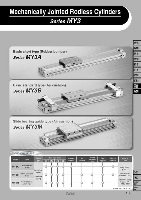
Mechanically Jointed Rodless Cylinders<br />
Series MY3<br />
MY1B<br />
Basic short type (Rubber bumper)<br />
Series <strong>MY3A</strong><br />
Basic standard type (Air cushion)<br />
Series MY3B<br />
MY1M<br />
MY1C<br />
MY1H<br />
MY1HT<br />
MY1W<br />
MY2C<br />
MY2H<br />
<strong>MY3A</strong><br />
MY3B<br />
MY3M<br />
Slide bearing guide type (Air cushion)<br />
Series MY3M<br />
Series Variations<br />
Series<br />
Type<br />
Piping<br />
type<br />
16<br />
Bore size (mm)<br />
25 40 63<br />
Rubber<br />
bumper<br />
Air<br />
cushion<br />
Stroke<br />
adjusting<br />
unit<br />
Side<br />
support<br />
Floating<br />
bracket<br />
Made to<br />
Order<br />
<strong>MY3A</strong><br />
MY3B<br />
MY3M<br />
Basic short<br />
type<br />
Basic standard<br />
type<br />
Slide bearing<br />
guide type<br />
Centralized<br />
piping<br />
Standard<br />
piping<br />
Long stroke<br />
(-XB11)<br />
Helical insert<br />
threads (-X168)<br />
Holder mounting<br />
bracket Note)<br />
(-X416, X417)<br />
D-<br />
-X<br />
Individual<br />
-X<br />
Note) Except the <strong>MY3A</strong><br />
1121<br />
Technical<br />
data
<strong>SMC</strong><br />
High functionality with reduced height and length<br />
Mechanically Jointed Rodless Cylinders<br />
Series MY3<br />
<strong>MY3A</strong><br />
Basic short type<br />
(Rubber bumper)<br />
MY3B<br />
Basic standard type<br />
(Air cushion)<br />
MY3M<br />
Slide bearing guide type<br />
(Air cushion)<br />
Work pieces can be loaded<br />
directly on the work table<br />
due to the integrated guide.<br />
Overall length (Z) reduced by 140 mm at the maximum<br />
Loading Capacity<br />
Load mass (kg)<br />
200<br />
180<br />
160<br />
140<br />
120<br />
100<br />
80<br />
60<br />
40<br />
20<br />
0<br />
m1<br />
MY3M<br />
<strong>MY3A</strong><br />
MY3B<br />
Height (H) reduced by 36% at the maximum<br />
Allowable moment (Nm)<br />
0<br />
16 25 40 63 16 25<br />
Bore size (mm)<br />
70<br />
60<br />
50<br />
40<br />
30<br />
20<br />
10<br />
M2<br />
40 63<br />
Bore size (mm)<br />
MY3M<br />
<strong>MY3A</strong><br />
MY3B<br />
<strong>MY3A</strong> (with rubber bumper)<br />
Height (H)<br />
<strong>SMC</strong><br />
Height (H)<br />
<strong>SMC</strong><br />
MY3B/MY3M (with air cushion)<br />
MY1B/MY1M (with air cushion)<br />
Overall length (Z + Stroke)<br />
MY1B <strong>MY3A</strong>/3B MY1M MY3M<br />
Height (H)<br />
Series<br />
<strong>MY3A</strong><br />
MY3B<br />
MY1B<br />
ø16 ø25 ø40 ø63<br />
27 37 54 84<br />
37 54 84 116<br />
MY3M 33 45 63 93<br />
MY1M 40 54 84 130<br />
(mm)<br />
Mass reduced by 53% at the maximum<br />
Overall Length (Z)<br />
1122<br />
Series<br />
<strong>MY3A</strong><br />
MY3B<br />
MY3M<br />
MY1B<br />
MY1M<br />
ø16<br />
110<br />
ø25<br />
150<br />
ø40<br />
240<br />
ø63<br />
320<br />
122 178 276 356<br />
160 220 340 460<br />
(mm)<br />
Mass<br />
Series<br />
<strong>MY3A</strong><br />
MY3B<br />
MY1B<br />
MY3M<br />
MY1M<br />
∗ At 100 mm stroke<br />
ø16<br />
0.34<br />
0.35<br />
0.73<br />
0.45<br />
0.91<br />
ø25<br />
0.99<br />
1.09<br />
1.57<br />
1.32<br />
2.12<br />
ø40<br />
2.95<br />
3.08<br />
4.41<br />
3.65<br />
7.00<br />
(kg)<br />
ø63<br />
8.26<br />
8.99<br />
14.5<br />
9.99<br />
18.9
Stroke Adjusting Unit<br />
Floating Bracket<br />
Easy connection with external guide. Vertical and lateral mounting is possible. (Page 1144)<br />
(MY3B/3M)<br />
(<strong>MY3A</strong>/3B)<br />
MY1B<br />
MY1M<br />
MY1C<br />
MY1H<br />
MY1HT<br />
MY1W<br />
MY2C<br />
MY2H<br />
<strong>MY3A</strong><br />
MY3B<br />
MY3M<br />
Side Support<br />
The cylinder tube can be fixed from the upper or lower side.<br />
(Page 1143, 1155)<br />
Centralized Piping<br />
Integrated piping in the<br />
head cover is possible.<br />
(Page 1158.)<br />
Auto Switch<br />
Can be mounted on both sides<br />
from the front direction.<br />
The uniquely designed piston<br />
shape enables reduction of<br />
the height and length as well<br />
as practical arrangement of<br />
the common piping passages,<br />
cushion mechanism and<br />
positioning mechanism. This<br />
has achieved drastic miniaturization<br />
and weight reduction.<br />
Positioning cushion mechanism<br />
Auto switch<br />
Side support<br />
Air cushion<br />
(MY3B/3M)<br />
Passage for<br />
centralized piping<br />
1123<br />
D-<br />
-X<br />
Individual<br />
-X<br />
Technical<br />
data
Series MY3<br />
Model Selection 1<br />
The following are steps for selecting the MY3 series which is best suited to your application.<br />
Guideline for Tentative Model Selection<br />
Guideline for tentative model selection<br />
Series Type Note<br />
Stroke accuracy Use of external guide Direct loaded Table accuracy<br />
<strong>MY3A</strong><br />
Basic short type<br />
Generally combined with a separare<br />
guide making it, by length, more compact.<br />
MY3B<br />
MY3M<br />
Basic standard type<br />
Slide bearing guide<br />
type<br />
Generally combined with a separare<br />
guide, when stroke accuracy is required.<br />
Mounting a work piece directly on the<br />
product, when stroke accuracy is required.<br />
Most suitable Suitable Usable Not recommended<br />
Note) The table accuracy means the amount of table deflection when a moment is applied.<br />
Selection Flow Chart<br />
When an external guide is used, the selection confirmation of the guide capacity should follow the selection procedure<br />
of the external guide.<br />
The MY3 series allow direct load application within the allowable range for the built-in guide. The payload in this case<br />
will vary depending on the driving speed and the mounting orientation of the cylinder. Please refer to the flow below and<br />
confirm the selection. (For more detailed description of the selection flow, please refer to the instruction manual.)<br />
Operating conditions<br />
m: Load mass (kg) Mounting<br />
V : Speed (mm/s) direction:<br />
P : Operating pressure (MPa)<br />
Re-examine the operating conditions.<br />
Tentative selection of cylinder model<br />
<strong>MY3A</strong>: Basic short type<br />
MY3B: Basic standard type<br />
MY3M: Slide bearing guide type<br />
Select larger<br />
cylinder size.<br />
Change the<br />
guide type.<br />
Determination<br />
of load mass<br />
and allowable<br />
moment<br />
NG<br />
In case of the <strong>MY3A</strong><br />
and MY3B only<br />
Select the<br />
different guide type.<br />
∗Please refer to the information<br />
by the guide<br />
manufacturer.<br />
NG<br />
OK<br />
OK<br />
Examine the cushioning<br />
mechanism at stroke end.<br />
Built-in cushion<br />
stroke adjusting<br />
unit<br />
NG<br />
External<br />
shock<br />
absorber<br />
NG<br />
OK<br />
OK<br />
1124<br />
Examine the auto switch<br />
mounting (model).<br />
Model<br />
selected<br />
∗ When using an external cushioning unit, we recommend installing a suitable unit near the load’s<br />
center of gravity.<br />
It is possible to select all models of mechanically jointed rodless cylinder (the MY3 series) according<br />
to the procedure indicated above.<br />
Refer to the separate instruction manual for further explanation, and please consult with <strong>SMC</strong><br />
regarding any questions.
Mechanically Jointed Rodless Cylinders Series MY3<br />
How to mount<br />
a load<br />
Stroke positioning<br />
Shock absorber<br />
Maximum operating speed<br />
(mm/s)<br />
500<br />
1000 1500<br />
Rubber bumper<br />
<strong>MY3A</strong><br />
MY1B<br />
MY1M<br />
Cylinder stroke end<br />
MY3B<br />
MY1C<br />
Air cushion<br />
MY1H<br />
Direct loaded<br />
MY3M<br />
MY1HT<br />
MY1W<br />
Stroke adjusting unit<br />
(Option: L, H unit)<br />
Shock absorber<br />
MY3M<br />
Note 4)<br />
MY2C<br />
MY2H<br />
<strong>MY3A</strong><br />
MY3B<br />
<strong>MY3A</strong><br />
MY3B<br />
MY3M<br />
External stopper<br />
External shock<br />
absorber<br />
Note 1)<br />
Note 2)<br />
MY3M<br />
Note 2)<br />
Rubber bumper<br />
<strong>MY3A</strong><br />
Cylinder stroke end<br />
Use of external<br />
guide<br />
Air cushion<br />
MY3B<br />
Stroke adjusting unit<br />
(Option: L, H unit)<br />
Shock absorber<br />
MY3B<br />
Note 3)<br />
Note 4)<br />
External stopper<br />
External shock<br />
absorber<br />
Note 1)<br />
<strong>MY3A</strong><br />
MY3B<br />
Note 2)<br />
Note 1) The shock absorber must meet the conditions mentioned on page 1135.<br />
Note 2) As the external shock absorber, a unit with appropriate capacity and features should be installed close to the load center of gravity.<br />
Note 3) Use the stroke adjusting unit of the MY3B series with an external guide.<br />
Note 4) Shown below are the details of the maximum operating speed for the stroke adjusting unit.<br />
MY3 Series, Maximum Operating Speed when Using the Stroke Adjusting Unit<br />
Series Bore size (mm) Stroke adjustment range Inside the fine stroke adjustment range<br />
L unit<br />
800<br />
16<br />
MY3B<br />
H unit<br />
1000<br />
25, 40, 63<br />
L, H unit<br />
1000<br />
MY3M 16, 25, 40, 63<br />
L, H unit<br />
1500<br />
Outside the fine stroke adjustment range means that when a holder mounting bracket (X416, X417) is used.<br />
Holder mounting bracket → Refer to page 1558.<br />
Unit: mm/s<br />
Outside the fine stroke adjustment range<br />
500<br />
800<br />
800<br />
800<br />
1125<br />
D-<br />
-X<br />
Individual<br />
-X<br />
Technical<br />
data
Series MY3<br />
Types of Moment Applied to Rodless Cylinders<br />
Multiple moments may be generated depending on the mounting orientation, load and position of the center of gravity.<br />
Coordinates and Moments<br />
Load Mass and Static Moment<br />
x<br />
M2: Rolling<br />
z<br />
M3: Yawing<br />
M1: Pitching<br />
y<br />
Horizontal<br />
mounting<br />
x<br />
M2<br />
Y<br />
Vertical<br />
mounting<br />
z<br />
M3<br />
Y<br />
X<br />
m1 x g<br />
M1<br />
Z<br />
m4 x g<br />
M1<br />
g: Gravitational acceleration<br />
y<br />
y<br />
x<br />
Ceiling<br />
mounting<br />
M2<br />
Y<br />
Mounting direction<br />
Static load m<br />
Static<br />
moment<br />
M1<br />
M2<br />
M3<br />
X<br />
m2 x g<br />
M1<br />
y<br />
x<br />
Wall<br />
mounting<br />
M2<br />
Z<br />
X<br />
m3 x g<br />
Note) m4 is a mass movable by thrust. Use 0.3 to 0.7 times the thrust<br />
(differs depending on the operating speed) as a guide for actual use.<br />
M3<br />
Horizontal<br />
m1<br />
Ceiling<br />
m2<br />
Wall<br />
m3<br />
Vertical<br />
Note)<br />
m4<br />
m1 x g x X m2 x g x X — m4 x g x Z<br />
m1 x g x Y m2 x g x Y m3 x g x Z —<br />
— — m3 x g x X m4 x g x Y<br />
z<br />
Dynamic Moment<br />
M1<br />
M1E<br />
FE<br />
Z<br />
υa<br />
mn x g<br />
M3E<br />
FE<br />
Y<br />
υa<br />
mn x g<br />
M3<br />
g : Gravitational acceleration<br />
υa: Average speed<br />
δ : Bumper coefficient<br />
Mounting direction Horizontal Ceiling Wall Vertical<br />
Dynamic load FE<br />
1.4υa x δ x mn x g<br />
Dynamic<br />
moment<br />
M1E<br />
M2E<br />
M3E<br />
1<br />
x FE<br />
3 x Z<br />
Dynamic moment M2E will not be generated.<br />
1<br />
x FE<br />
3 x Y<br />
Note) Regardless of the mounting orientation, dynamic moment is<br />
calculated with the formulae above.<br />
Calculation of Guide Load Factor<br />
1. Maximum load mass (1), static moment (2), and dynamic moment (3) (at the time of impact with stopper) must be examined for the selection calculations.<br />
∗ To evaluate, use υa (average speed) for (1) and (2), and υ (impact speed υ = 1.4υa) for (3). Calculate m max for (1) from the maximum allowable load graph (m1, m2, m3 )<br />
and Mmax for (2) and (3) from the maximum allowable moment graph (M1, M2, M3).<br />
Sum of guide<br />
load factors<br />
Load mass [m] Static moment [M] Dynamic moment [ME]<br />
Σα = + + 1<br />
Maximum load mass<br />
[m max]<br />
Note 1)<br />
Allowable static moment<br />
[Mmax]<br />
Allowable dynamic moment<br />
[MEmax]<br />
Note 1) Moment caused by the load, etc., with cylinder in resting condition.<br />
Note 2) Moment caused by the impact load equivalent at the stroke end (at the time of impact with stopper).<br />
Note 3) Depending on the shape of the work piece, multiple moments may occur. When this happens, the sum of the load factors (Σα) is the total of all such moments.<br />
Note 2)<br />
2. Reference formulas [Dynamic moment at impact]<br />
Use the following formulas to calculate dynamic moment when taking stopper impact into consideration.<br />
m : Load mass (kg)<br />
υ : Impact speed (mm/s)<br />
F : Load (N)<br />
FE : Load equivalent to impact (at impact with stopper) (N)<br />
υa : Average speed (mm/s)<br />
M : Static moment (N • m)<br />
Note 4)<br />
υ = 1.4υa (mm/s) FE = 1.4υa x δ x m • g<br />
Note 5)<br />
1<br />
•<br />
• • ME = — • FE • L1 = 4.57υaδm L1 (N • m)<br />
3<br />
Note 4) 1.4υaδ is a dimension less coefficient for calculating impact force.<br />
1<br />
Note 5) Average load coefficient = ( :<br />
3<br />
)<br />
This coefficient is for averaging the maximum load moment at the time of stopper impact according to service life calculations.<br />
3. For detailed selection procedure, please refer to pages 1130, 1131, 1146, 1147.<br />
1126<br />
L1 : Distance to the load’s center of gravity (m)<br />
ME: Dynamic moment (N • m)<br />
δ : Bumper coefficient<br />
With rubber bumper = 4/100<br />
With air cushion = 1/100<br />
With shock absorber = 1/100<br />
g : Gravitational acceleration (9.8 m/s 2 )<br />
L1<br />
υ<br />
m<br />
FE<br />
ME
Series MY3<br />
Model Selection 2<br />
The following are steps for selecting the MY3 series which is best suited to your application.<br />
Calculation of Guide Load Factor<br />
1 Operating Conditions<br />
Cylinder •••••••••••••••••••••••••••••••••••••• <strong>MY3A</strong>25-500<br />
Average operating speed υa •••••••••• 300 mm/s<br />
Mounting direction ••••••••••••••••••••••• Horizontal mounting<br />
Cushion •••••••••••••••••••••••••••••••••••••• Rubber bumper (δ = 4/100)<br />
2 Load Blocking<br />
20<br />
Z<br />
W: Work piece (0.8 kg)<br />
5<br />
Y<br />
X<br />
<strong>MY3A</strong>25-500<br />
Work piece<br />
no.<br />
W<br />
Mounting Direction<br />
1. Horizontal z 2. Wall<br />
mounting<br />
mounting<br />
Page 948<br />
x<br />
y<br />
x<br />
3. Ceiling<br />
mounting<br />
Page 998<br />
x<br />
z<br />
y<br />
4. Vertical<br />
mounting<br />
Page 1042<br />
z<br />
Refer to the pages mentioned above for actual examples of calculation for each orientation.<br />
Work Piece Mass and Center of Gravity<br />
Mass<br />
(m)<br />
0.8 kg<br />
X-axis<br />
5 mm<br />
Center of gravity<br />
Y-axis<br />
10 mm<br />
x<br />
y<br />
Z-axis<br />
20 mm<br />
z<br />
y<br />
MY1B<br />
MY1M<br />
MY1C<br />
MY1H<br />
MY1HT<br />
MY1W<br />
MY2C<br />
MY2H<br />
<strong>MY3A</strong><br />
MY3B<br />
MY3M<br />
Y<br />
10<br />
3 Calculation of Load Factor for Static Load<br />
m1: Mass<br />
m1 max (from q of graph <strong>MY3A</strong> ⁄ m1) = 10.7 (kg) • ••••••••••••••••••••••••••••••••••••••••<br />
m1<br />
Load factor 1 = m1 ⁄ m1 max = 0.8 ⁄ 10.7 = 0.08<br />
M1: Moment<br />
X<br />
M1 max (from w of graph <strong>MY3A</strong> ⁄ M1) = 4 (Nm) ••••••••••••••••••••••••••••••••••••••••••••••••••••••••••••••••••<br />
m1<br />
M1 = m1 x g x X = 0.8 x 9.8 x 5 x 10 -3 = 0.04 (Nm)<br />
Load factor 2 = M1 ⁄ M1 max = 0.04 ⁄ 4 = 0.01<br />
M1<br />
M2: Moment<br />
Y<br />
M2 max (from e of graph <strong>MY3A</strong> ⁄ M2) = 0.8 (Nm) ••••••••••••••••••••••••••••••••••••••••••••••••••••••••••••••<br />
M3 = m1 x g x Y = 0.8 x 9.8 x 10 x 10 -3 = 0.08 (Nm)<br />
m1<br />
Load factor 3 = M2 ⁄ M2 max = 0.08 ⁄ 0.8 = 0.1<br />
M2<br />
D-<br />
1127<br />
-X<br />
Individual<br />
-X<br />
Technical<br />
data
Series MY3<br />
Calculation of Guide Load Factor<br />
4 Calculation of Load Factor for Dynamic Moment<br />
Equivalent load FE at impact<br />
FE = 1.4υa x δ x m x g = 1.4 x 300 x ——<br />
4<br />
x 0.8 x 9.8 = 131.7 (N)<br />
100<br />
M1E: Moment<br />
M1E max (from r of graph <strong>MY3A</strong> ⁄ M1 where 1.4υa = 420 mm/s) = 2.85 (Nm) ••••••••••••••<br />
M1E = ——<br />
1<br />
x FE x Z = ——<br />
1<br />
x 131.7 x 20 x 10 -3 = 0.88 (Nm)<br />
3 3<br />
Load factor 4 = M1E ⁄ M1E max = 0.88 ⁄ 2.85 = 0.31<br />
M3E: Moment<br />
M3E max (from t of graph <strong>MY3A</strong> ⁄ M3 where 1.4υa = 420 mm/s) = 0.95 (Nm) ••••••••••••••••••••<br />
M3E = ——<br />
1<br />
x FE x Y = ——<br />
1<br />
x 131.7 x 10 x 10 -3 = 0.44 (Nm)<br />
3 3<br />
Load factor 5 = M3E ⁄ M3E max = 0.44 ⁄ 0.95 = 0.43<br />
FE<br />
M1E<br />
M3<br />
FE<br />
M3E<br />
M1<br />
Y<br />
Z<br />
5 Sum and Examination of Guide Load Factors<br />
The above calculation is within the allowable value, and therefore the selected model can be used.<br />
Select a shock absorber separately.<br />
In an actual calculation, when the sum of guide load factors Σα in the formula above is more than 1, consider<br />
decreasing the speed, increasing the bore size, or changing the product series.<br />
Load Mass<br />
Allowable Moment<br />
<strong>MY3A</strong>, MY3B/m1 <strong>MY3A</strong>, MY3B/M1<br />
<strong>MY3A</strong>, MY3B/M2 <strong>MY3A</strong>, MY3B/M3<br />
Load mass (kg)<br />
200<br />
100<br />
50<br />
40<br />
30<br />
20<br />
10<br />
5<br />
4<br />
3<br />
2<br />
1<br />
<strong>MY3A</strong> / 3B63<br />
<strong>MY3A</strong> / 3B40<br />
<strong>MY3A</strong> / 3B25<br />
<strong>MY3A</strong> / 3B16<br />
Moment (Nm)<br />
100<br />
50<br />
40<br />
30<br />
20<br />
10<br />
5<br />
4<br />
3<br />
2<br />
1<br />
0.5<br />
0.4<br />
0.3<br />
0.2<br />
<strong>MY3A</strong> / 3B63<br />
<strong>MY3A</strong> / 3B40<br />
<strong>MY3A</strong> / 3B25<br />
<strong>MY3A</strong> / 3B16<br />
Moment (Nm)<br />
30<br />
20<br />
10<br />
5<br />
4<br />
3<br />
2<br />
1<br />
0.5<br />
0.4<br />
0.3<br />
0.2<br />
0.1<br />
0.05<br />
<strong>MY3A</strong> / 3B63<br />
<strong>MY3A</strong> / 3B40<br />
<strong>MY3A</strong> / 3B25<br />
<strong>MY3A</strong> / 3B16<br />
Moment (Nm)<br />
50<br />
40<br />
30<br />
20<br />
10<br />
5<br />
4<br />
3<br />
2<br />
1<br />
0.5<br />
0.4<br />
0.3<br />
0.2<br />
0.1<br />
<strong>MY3A</strong> / 3B63<br />
<strong>MY3A</strong> / 3B40<br />
<strong>MY3A</strong> / 3B25<br />
<strong>MY3A</strong> / 3B16<br />
0.5<br />
100 200 300 400 500 1000 1500<br />
Piston speed (mm/s)<br />
∗ Refer to page 1147 for the MY3M.<br />
0.1<br />
0.05<br />
100 200 300 400 500 1000 1500<br />
100 200 300 400 500 1000 1500<br />
100 200 300 400 500 1000 1500<br />
Piston speed (mm/s) Piston speed (mm/s) Piston speed (mm/s)<br />
1128
Series <strong>MY3A</strong><br />
Basic, short type (Rubber bumper)<br />
ø16, ø25, ø40, ø63<br />
MY1B<br />
MY1M<br />
MY1C<br />
MY1H<br />
MY1HT<br />
MY1W<br />
MY2C<br />
MY2H<br />
<strong>MY3A</strong><br />
MY3B<br />
MY3M<br />
Series MY3B<br />
Basic, standard type (Air cushion)<br />
ø16, ø25, ø40, ø63<br />
D-<br />
1129<br />
-X<br />
Individual<br />
-X<br />
Technical<br />
data
Series <strong>MY3A</strong>/3B<br />
Model Selection<br />
The following are steps for selecting the MY3 series which is best suited to your application.<br />
Calculation of Guide Load Factor<br />
1 Operating Conditions<br />
Cylinder •••••••••••••••••••••••••••••••••••••• <strong>MY3A</strong>25-500<br />
Average operating speed υa •••••••••• 300 mm/s<br />
Mounting direction ••••••••••••••••••••••• Horizontal mounting<br />
Cushion •••••••••••••••••••••••••••••••••••••• Rubber bumper (δ = 4/100)<br />
W: Work piece (0.8 kg)<br />
Mounting Direction<br />
1. Horizontal z 2. Wall<br />
mounting<br />
mounting<br />
Page 948<br />
x<br />
y<br />
x<br />
y<br />
z<br />
3. Ceiling<br />
mounting<br />
Page 998<br />
x<br />
z<br />
y<br />
4. Vertical<br />
mounting<br />
Page 1042<br />
z<br />
x<br />
y<br />
2 Load Blocking<br />
<strong>MY3A</strong>25-500<br />
Refer to the pages mentioned above for actual examples of calculation for each orientation.<br />
Y<br />
Work Piece Mass and Center of Gravity<br />
Z<br />
5<br />
X<br />
Work piece<br />
no.<br />
W<br />
Mass<br />
(m)<br />
0.8 kg<br />
X-axis<br />
5 mm<br />
Center of gravity<br />
Y-axis<br />
10 mm<br />
Z-axis<br />
20 mm<br />
20<br />
Y<br />
10<br />
3 Calculation of Load Factor for Static Load<br />
m1: Mass<br />
m1 max (from q of graph <strong>MY3A</strong> ⁄ m1) = 10.7 (kg) • ••••••••••••••••••••••••••••••••••••••••<br />
m1<br />
Load factor 1 = m1 ⁄ m1 max = 0.8 ⁄ 10.7 = 0.08<br />
M1: Moment<br />
X<br />
M1 max (from w of graph <strong>MY3A</strong> ⁄ M1) = 4 (Nm) ••••••••••••••••••••••••••••••••••••••••••••••••••••••••••••••••••<br />
m1<br />
M1 = m1 x g x X = 0.8 x 9.8 × 5 x 10 -3 = 0.04 (Nm)<br />
Load factor 2 = M1 ⁄ M1 max = 0.04 ⁄ 4 = 0.01<br />
M1<br />
M2: Moment<br />
Y<br />
M2 max (from e of graph <strong>MY3A</strong> ⁄ M2) = 0.8 (Nm) ••••••••••••••••••••••••••••••••••••••••••••••••••••••••••••••<br />
M3 = m1 x g x Y = 0.8 x 9.8 x 10 x 10 -3 = 0.08 (Nm)<br />
m1<br />
Load factor 3 = M2 ⁄ M2 max = 0.08 ⁄ 0.8 = 0.1<br />
M2<br />
1130
Mechanically Jointed Rodless Cylinders Series <strong>MY3A</strong>/3B<br />
Calculation of Guide Load Factor<br />
4 Calculation of Load Factor for Dynamic Moment<br />
Equivalent load FE at impact<br />
FE = 1.4υa x δ x m x g = 1.4 x 300 x ——<br />
4<br />
x 0.8 x 9.8 = 131.7 (N)<br />
100<br />
M1E: Moment<br />
M1E max (from r of graph <strong>MY3A</strong> ⁄ M1 where 1.4υa = 420 mm/s) = 2.85 (Nm) ••••••••••••••<br />
M1E = ——<br />
1<br />
x FE x Z = ——3<br />
1<br />
x 131.7 x 20 x 10 -3 = 0.88 (Nm)<br />
3<br />
Load factor 4 = M1E ⁄ M1E max = 0.88 ⁄ 2.85 = 0.31<br />
M3E: Moment<br />
M3E max (from t of graph <strong>MY3A</strong> ⁄ M3 where 1.4υa = 420 mm/s) = 0.95 (Nm) ••••••••••••••••••••<br />
M3E = ——<br />
1<br />
1<br />
x FE x Y = x 131.7 x 10 x 10 -3 = 0.44 (Nm)<br />
3<br />
Load factor 5 = M3E ⁄ M3E max = 0.44 ⁄ 0.95 = 0.43<br />
——3<br />
1131<br />
FE<br />
M1E<br />
M3<br />
FE<br />
M3E<br />
M1<br />
Y<br />
Z<br />
MY1B<br />
MY1M<br />
MY1C<br />
MY1H<br />
MY1HT<br />
MY1W<br />
MY2C<br />
MY2H<br />
<strong>MY3A</strong><br />
MY3B<br />
5 Sum and Examination of Guide Load Factors<br />
MY3M<br />
The above calculation is within the allowable value, and therefore the selected model can be used.<br />
Select a shock absorber separately.<br />
In an actual calculation, when the sum of guide load factors Σα in the formula above is more than 1, consider<br />
decreasing the speed, increasing the bore size, or changing the product series.<br />
Load Mass<br />
Allowable Moment<br />
<strong>MY3A</strong>, MY3B/m1 <strong>MY3A</strong>, MY3B/M1<br />
<strong>MY3A</strong>, MY3B/M2 <strong>MY3A</strong>, MY3B/M3<br />
Load mass (kg)<br />
200<br />
100<br />
50<br />
40<br />
30<br />
20<br />
10<br />
5<br />
4<br />
3<br />
2<br />
1<br />
ø63<br />
ø40<br />
ø25<br />
ø16<br />
Moment (Nm)<br />
100<br />
50<br />
40<br />
30<br />
20<br />
10<br />
5<br />
4<br />
3<br />
2<br />
1<br />
0.5<br />
0.4<br />
0.3<br />
0.2<br />
ø63<br />
ø40<br />
ø25<br />
ø16<br />
Moment (Nm)<br />
30<br />
20<br />
10<br />
5<br />
4<br />
3<br />
2<br />
1<br />
0.5<br />
0.4<br />
0.3<br />
0.2<br />
0.1<br />
0.05<br />
ø63<br />
ø40<br />
ø25<br />
ø16<br />
Moment (Nm)<br />
50<br />
40<br />
30<br />
20<br />
10<br />
5<br />
4<br />
3<br />
2<br />
1<br />
0.5<br />
0.4<br />
0.3<br />
0.2<br />
0.1<br />
ø63<br />
ø40<br />
ø25<br />
ø16<br />
0.5<br />
100 200 300 400 500 1000 1500<br />
Piston speed (mm/s)<br />
∗ Refer to page 1147 for the MY3M.<br />
0.1<br />
0.05<br />
100 200 300 400 500 1000 1500<br />
100 200 300 400 500 1000 1500<br />
100 200 300 400 500 1000 1500<br />
Piston speed (mm/s) Piston speed (mm/s) Piston speed (mm/s)<br />
D-<br />
-X<br />
Individual<br />
-X<br />
Technical<br />
data
Series <strong>MY3A</strong>/3B<br />
Maximum Allowable Moment / Maximum Allowable Load<br />
Series<br />
<strong>MY3A</strong><br />
MY3B<br />
Bore size<br />
(mm)<br />
16<br />
25<br />
40<br />
63<br />
Maximum allowable moment (Nm)<br />
M1 M2 M3<br />
1.8<br />
6<br />
24<br />
70<br />
0.3<br />
1.2<br />
4.8<br />
19<br />
0.7<br />
2<br />
10<br />
30<br />
Maximum allowable load (kg)<br />
m1 m2 m3<br />
6<br />
16<br />
40<br />
80<br />
3<br />
6<br />
12<br />
24<br />
1.5<br />
4<br />
10<br />
20<br />
The above values are the maximum allowable values for moment and load. Refer to each graph regarding the maximum<br />
allowable moment and maximum allowable load for a particular piston speed.<br />
Maximum Allowable Moment<br />
<strong>MY3A</strong>, MY3B/M1<br />
Moment (Nm)<br />
100<br />
50<br />
40<br />
30<br />
20<br />
10<br />
5<br />
4<br />
3<br />
2<br />
1<br />
0.5<br />
0.4<br />
0.3<br />
0.2<br />
ø63<br />
ø40<br />
ø25<br />
ø16<br />
Select the moment from within the range of operating limits shown in the graphs. Note that the maximum allowable load value may sometimes<br />
be exceeded even within the operating limits shown in the graphs. Therefore, also check the allowable load for the selected conditions.<br />
<strong>MY3A</strong>, MY3B/M2<br />
Moment (Nm)<br />
30<br />
20<br />
10<br />
5<br />
4<br />
3<br />
2<br />
1<br />
0.5<br />
0.4<br />
0.3<br />
0.2<br />
0.1<br />
0.05<br />
ø63<br />
ø40<br />
ø25<br />
ø16<br />
<strong>MY3A</strong>, MY3B/M3<br />
Moment (Nm)<br />
50<br />
40<br />
30<br />
20<br />
10<br />
5<br />
4<br />
3<br />
2<br />
1<br />
0.5<br />
0.4<br />
0.3<br />
0.2<br />
0.1<br />
ø63<br />
ø40<br />
ø25<br />
ø16<br />
0.1<br />
100<br />
200<br />
300 400 500<br />
1000 1500<br />
100<br />
200<br />
300 400 500<br />
1000 1500<br />
0.05<br />
100<br />
200<br />
300 400 500<br />
1000 1500<br />
<strong>MY3A</strong> max. MY3B max.<br />
Piston speed (mm/s)<br />
<strong>MY3A</strong> max. MY3B max.<br />
Piston speed (mm/s)<br />
<strong>MY3A</strong> max. MY3B max.<br />
Piston speed (mm/s)<br />
Maximum Allowable Load<br />
Select the load from within the range of limits shown in the graphs. Note that the maximum allowable moment value may sometimes be<br />
exceeded even within the operating limits shown in the graphs. Therefore, also check the allowable moment for the selected conditions.<br />
<strong>MY3A</strong>, MY3B/m1 <strong>MY3A</strong>, MY3B/m2 <strong>MY3A</strong>, MY3B/m3<br />
Load mass (kg)<br />
200<br />
100<br />
50<br />
40<br />
30<br />
20<br />
10<br />
5<br />
4<br />
3<br />
2<br />
1<br />
ø63<br />
ø40<br />
ø25<br />
ø16<br />
Load mass (kg)<br />
100<br />
50<br />
40<br />
30<br />
20<br />
10<br />
5<br />
4<br />
3<br />
2<br />
1<br />
0.5<br />
ø63<br />
ø40<br />
ø25<br />
ø16<br />
Load mass (kg)<br />
50<br />
40<br />
30<br />
20<br />
10<br />
5<br />
4<br />
3<br />
2<br />
1<br />
0.5<br />
0.4<br />
0.3<br />
0.2<br />
ø63<br />
ø40<br />
ø25<br />
ø16<br />
0.5<br />
100<br />
200<br />
300 400 500<br />
1000<br />
1500<br />
100<br />
200<br />
300 400 500<br />
1000 1500<br />
0.1<br />
100<br />
200<br />
300 400 500<br />
1000 1500<br />
1132<br />
<strong>MY3A</strong> max. MY3B max.<br />
Piston speed (mm/s)<br />
<strong>MY3A</strong> max.<br />
MY3B max.<br />
Piston speed (mm/s)<br />
<strong>MY3A</strong> max. MY3B max.<br />
Piston speed (mm/s)
Mechanically Jointed Rodless Cylinders Series <strong>MY3A</strong>/3B<br />
Cushion Capacity<br />
Absorption Capacity of Rubber Bumper (<strong>MY3A</strong>)<br />
<strong>MY3A</strong>16<br />
1000<br />
Horizontal collision: P = 0.5 MPa<br />
<strong>MY3A</strong>25<br />
1000<br />
Horizontal collision: P = 0.5 MPa<br />
MY1B<br />
Collision speed (mm/s)<br />
500<br />
400<br />
300<br />
200<br />
Rubber bumper<br />
Collision speed (mm/s)<br />
500<br />
400<br />
300<br />
200<br />
Rubber bumper<br />
MY1M<br />
MY1C<br />
MY1H<br />
MY1HT<br />
100<br />
80<br />
0.2<br />
0.3<br />
0.4<br />
1<br />
m3max<br />
m2max<br />
Load mass (kg)<br />
2<br />
3 4 5<br />
m1max<br />
100<br />
80<br />
1 2 3 4 5<br />
m3max<br />
m2max<br />
Load mass (kg)<br />
10<br />
m1max<br />
20<br />
MY1W<br />
MY2C<br />
MY2H<br />
<strong>MY3A</strong>40<br />
Horizontal collision: P = 0.5 MPa<br />
<strong>MY3A</strong>63<br />
Horizontal collision: P = 0.5 MPa<br />
<strong>MY3A</strong><br />
MY3B<br />
1000<br />
1000<br />
MY3M<br />
Collision speed (mm/s)<br />
500<br />
400<br />
300<br />
200<br />
Rubber bumper<br />
Collision speed (mm/s)<br />
500<br />
400<br />
300<br />
200<br />
Rubber bumper<br />
100<br />
100<br />
80<br />
1 2 3<br />
4<br />
5<br />
10 20 30 40<br />
80<br />
2 3 4 5<br />
10 20 30 40 100<br />
m3max m2max<br />
Load mass (kg)<br />
m1max<br />
m3max m2max<br />
Load mass (kg)<br />
m1max<br />
Rubber Bumper Displacement (Additional Stroke due to Pressure on Each Side)<br />
The stop position of the built-in rubber bumper of the <strong>MY3A</strong> series varies depending on the operating pressure. For alignement at<br />
the stroke end, find the guideline for the stroke end position in operation as follows. Find the incremental displacement at the operating<br />
pressure in the graph and add it to the stroke end position at no pressurization. If positioning accuracy is required for the<br />
stop position at the stroke end, consider installing an external positioning mechanism or switching to the air cushion type (MY3B).<br />
<strong>MY3A</strong>16<br />
(Horizontal)<br />
<strong>MY3A</strong>25<br />
(Horizontal)<br />
<strong>MY3A</strong>40<br />
(Horizontal)<br />
<strong>MY3A</strong>63<br />
(Horizontal)<br />
2.0<br />
2.0<br />
2.0<br />
2.5<br />
1.8<br />
1.8<br />
1.8<br />
Additional stroke (mm)<br />
1.6<br />
1.4<br />
1.2<br />
1.0<br />
0.8<br />
0.6<br />
0.4<br />
0.2<br />
0<br />
0.1 0.2 0.3 0.4 0.5 0.6<br />
Operating pressure (MPa)<br />
0.7 0.8<br />
Additional stroke (mm)<br />
1.6<br />
1.4<br />
1.2<br />
1.0<br />
0.8<br />
0.6<br />
0.4<br />
0.2<br />
0<br />
0.1 0.2 0.3 0.4 0.5 0.6<br />
Operating pressure (MPa)<br />
0.7 0.8<br />
0.1 0.2 0.3 0.4 0.5 0.6<br />
Operating pressure (MPa)<br />
Note) In vertical operation, find the guideline for the stroke end position by adding, in case of the lower end, or subtracting, in case of the upper end, the pressure displacement equivalent to the self mass of the load.<br />
Additional stroke (mm)<br />
1.6<br />
1.4<br />
1.2<br />
1.0<br />
0.8<br />
0.6<br />
0.4<br />
0.2<br />
0<br />
0.7 0.8<br />
Additional stroke (mm)<br />
2.0<br />
1.5<br />
1.0<br />
0.5<br />
0<br />
0.1 0.2 0.3 0.4 0.5 0.6<br />
Operating pressure (MPa)<br />
0.7 0.8<br />
1133<br />
D-<br />
-X<br />
Individual<br />
-X<br />
Technical<br />
data
Series <strong>MY3A</strong>/3B<br />
Cushion Capacity<br />
Absorption Capacity of Air Cushion and Stroke Adjusting Unit (MY3B)<br />
MY3B16<br />
Horizontal collision: P = 0.5 MPa<br />
MY3B25<br />
Horizontal collision: P = 0.5 MPa<br />
2000<br />
Maximum collision speed (H)<br />
with fixed intermediate position<br />
2000<br />
Maximum collision speed (H, L)<br />
with fixed intermediate position<br />
1000<br />
1000<br />
Collision speed (mm/s)<br />
500<br />
400<br />
300<br />
200<br />
L unit<br />
H unit<br />
Air cushion<br />
Maximum collision speed<br />
(L) with fixed intermediate<br />
position<br />
(Refer to Note 4 on<br />
page 1125.)<br />
Collision speed (mm/s)<br />
500<br />
400<br />
300<br />
200<br />
H unit<br />
Air cushion, L unit<br />
100<br />
100<br />
80<br />
0.2<br />
0.3 0.4 1 2 3 4 5 10<br />
80<br />
1<br />
2<br />
3<br />
4<br />
5 10 20 50<br />
m3max<br />
m2max<br />
Load mass (kg)<br />
m1max<br />
m3max<br />
m2max<br />
Load mass (kg)<br />
m1max<br />
MY3B40<br />
Horizontal collision: P = 0.5 MPa<br />
MY3B63<br />
Horizontal collision: P = 0.5 MPa<br />
2000<br />
Maximum collision speed (H, L)<br />
with fixed intermediate position<br />
2000<br />
Maximum collision speed (H, L)<br />
with fixed intermediate position<br />
1000<br />
1000<br />
Collision speed (mm/s)<br />
500<br />
400<br />
300<br />
H unit<br />
Air cushion, L unit<br />
Collision speed (mm/s)<br />
500<br />
400<br />
300<br />
H unit<br />
Air cushion, L unit<br />
200<br />
200<br />
100<br />
80<br />
1<br />
2<br />
3<br />
4<br />
5 10 20 30 40<br />
100<br />
80<br />
2<br />
3<br />
4<br />
5 10 20 30 40 100<br />
m3max<br />
m2max m1max<br />
Load mass (kg)<br />
m3max<br />
m2max<br />
Load mass (kg)<br />
m1max<br />
Air Cushion Stroke<br />
Bore size (mm)<br />
16<br />
25<br />
40<br />
63<br />
Cushion stroke<br />
13<br />
18<br />
25<br />
30<br />
Stroke Adjusting Unit<br />
Fine Stroke Adjustment Range<br />
Unit: mm<br />
Unit: mm<br />
Bore size (mm) Fine stroke adjustment range<br />
16<br />
0 to -10<br />
25<br />
0 to -12<br />
40<br />
0 to -16<br />
63<br />
0 to -24<br />
Note) The maximum operating speed will differ when the stroke<br />
adjusting unit is used outside the maximum fine stroke<br />
adjustment range (with reference to the fixed stroke end),<br />
such as at a fixed intermediate position (X416, X417).<br />
(Refer to the graph above.)<br />
1134<br />
Calculation of Absorbed Energy for Stroke<br />
Adjusting Unit with Built-in Shock Absorber<br />
Type of<br />
collision<br />
Kinetic<br />
energy E1<br />
Thrust<br />
energy E2<br />
Absorbed<br />
energy E<br />
Horizontal<br />
υ m<br />
F • s<br />
s<br />
Vertical<br />
(downward)<br />
1<br />
2<br />
υ m<br />
m •υ 2<br />
Unit: N • m<br />
Vertical<br />
(upward)<br />
F•s + m •g •s F•s - m •g •s<br />
E1 + E2<br />
s<br />
s<br />
υ m<br />
Symbols<br />
υ: Speed of impacting object (m/s)<br />
m: Mass of impacting object (kg)<br />
F : Cylinder thrust (N)<br />
g : Gravitational acceleration (9.8 m/s 2 )<br />
s : Shock absorber stroke (m)<br />
Note) The speed of the impacting object is<br />
measured at the time of collision with the<br />
shock absorber.<br />
Note) With an operating pressure of 0.6 MPa or<br />
larger, the use of a cushion or an external<br />
shock absorber conforming to the<br />
conditions on page 1135 is recommended.
Mechanically Jointed Rodless Cylinders Series <strong>MY3A</strong>/3B<br />
External Shock Absorber Selection<br />
When the positioning of the stop position is necessary or the absorption capacity of the built-in cushion is not<br />
sufficient, refer to the selection procedure below and consider the installation of an external shock absorber.<br />
Selection Confirmation Items with Use of External Shock Absorber<br />
q When the cylinder alone is used.<br />
Cylinder load factor selection<br />
External shock absorber<br />
Impact force and absorption<br />
capacity confirmation<br />
Allowable impact force with use of external shock absorber<br />
MY316<br />
Collision deceleration (G)<br />
50<br />
40<br />
30<br />
20<br />
10<br />
5<br />
4<br />
3<br />
2<br />
1<br />
0.2<br />
MY325<br />
Collision deceleration (G)<br />
50<br />
40<br />
30<br />
20<br />
10<br />
5<br />
4<br />
3<br />
2<br />
1<br />
MY340<br />
Collision deceleration (G)<br />
50<br />
40<br />
30<br />
20<br />
10<br />
5<br />
4<br />
3<br />
2<br />
1<br />
1<br />
1<br />
240 N<br />
0.3 0.4<br />
1 2 3 4 5 10<br />
m3max m2max<br />
m1max<br />
Mass (kg)<br />
2<br />
3<br />
2<br />
580 N<br />
3<br />
m3max<br />
4<br />
4<br />
5<br />
10<br />
m2max<br />
Mass (kg)<br />
1500 N<br />
5 10 20<br />
m3max m2max<br />
Mass (kg)<br />
30<br />
20<br />
m1max<br />
40<br />
m1max<br />
50<br />
MY363<br />
Collision deceleration (G)<br />
50<br />
40<br />
30<br />
20<br />
10<br />
5<br />
4<br />
3<br />
2<br />
1<br />
2<br />
3<br />
4<br />
5<br />
3700 N<br />
10 20 30 40<br />
100<br />
m3max m2max<br />
m1max<br />
Mass (kg)<br />
Note) The mass represents the equivalent mass including the thrust energy.<br />
w When the external guide is used.<br />
External guide load factor selection<br />
External shock absorber<br />
Impact force and absorption<br />
capacity confirmation<br />
Piston Speed with Use of External Shock Absorber<br />
Bore size (mm) 16 25 40<br />
<strong>MY3A</strong><br />
MY3B<br />
80 to 1500 mm/s<br />
An external shock absorber can be used within the above piston<br />
speed range. In conjunction with the absorption capacity<br />
selection, however, also confirm the conditions which make<br />
the shock absorber collision impact force to stay within the allowable<br />
range in the graph.<br />
Use of an external shock absorber with conditions exceeding<br />
the allowable range may damage the cylinder.<br />
To confirm the collision impact force of the shock absorber,<br />
first find the impact force or acceleration under the<br />
operating conditions using the selection information or<br />
selection software provided by the manufacturer and<br />
then, refer to the graph.<br />
(The selection should allow a sufficient margin because the<br />
value calculated by the selection software involves an error<br />
with reference to the actual value.)<br />
Example of Recommended Use of the<br />
External Shock Absorber<br />
MY316 RB–OEM0.25M<br />
MY325 RB–OEM0.5M<br />
MY340 RB–OEM1.0MF<br />
MY363 RB–OEM1.5M x 1<br />
63<br />
1135<br />
MY1B<br />
MY1M<br />
MY1C<br />
MY1H<br />
MY1HT<br />
MY1W<br />
MY2C<br />
MY2H<br />
<strong>MY3A</strong><br />
MY3B<br />
MY3M<br />
D-<br />
-X<br />
Individual<br />
-X<br />
Technical<br />
data
Mechanically Jointed Rodless Cylinder/Basic Type<br />
Series <strong>MY3A</strong>/3B<br />
ø16, ø25, ø40, ø63<br />
How to Order<br />
Basic<br />
A<br />
B<br />
MY3<br />
Type<br />
Short type<br />
(Rubber bumper)<br />
Standard type<br />
(Air cushion)<br />
Cylinder bore size<br />
Symbol<br />
Nil<br />
TN<br />
TF<br />
16<br />
25<br />
40<br />
63<br />
B<br />
16 mm<br />
25 mm<br />
40 mm<br />
63 mm<br />
Port thread type<br />
Type Bore size<br />
M thread ø16<br />
Rc<br />
NPT ø25, ø40, ø63<br />
G<br />
16 300 HL<br />
Stroke<br />
∗ Refer to “Standard Stroke” table.<br />
Symbol<br />
Nil<br />
L<br />
H<br />
LS<br />
SL<br />
HS<br />
SH<br />
LH<br />
HL<br />
M9BW<br />
Number of auto switches<br />
Nil<br />
S<br />
n<br />
2 pcs.<br />
1 pc.<br />
“n” pcs.<br />
Auto switch<br />
Nil Without auto switch (Built-in magnet)<br />
∗ Refer to the table below for auto switch model<br />
numbers.<br />
Stroke adjusting unit (∗ MY3B only)<br />
Stroke adjusting unit<br />
Without adjusting unit<br />
Made to Order<br />
For details, refer to page 1137.<br />
With shock absorbers for low load on both sides<br />
With shock absorbers for high load on both sides<br />
With a shock absorber for low load on left side<br />
With a shock absorber for low load on right side<br />
With a shock absorber for high load on left side<br />
With a shock absorber for high load on right side<br />
With L unit on left side and H unit on right side<br />
With H unit on left side and L unit on right side<br />
Applicable model<br />
<strong>MY3A</strong>, MY3B<br />
MY3B<br />
Standard Stroke<br />
Bore size<br />
(mm)<br />
16, 25<br />
40, 63<br />
Standard stroke (mm) ∗<br />
100, 200, 300, 400, 500, 600<br />
700, 800, 900, 1000, 1200<br />
1400, 1600, 1800, 2000<br />
Max. manufacturable<br />
stroke (mm)<br />
3000<br />
∗ Strokes are manufacturable in 1 mm increments, up to the maximum stroke.<br />
However, when exceeding 2000 mm stroke, add “-XB11” to the end of the<br />
model number. Refer to “Made to Order ” on page 1405.<br />
Stroke adjusting unit appearance and mounting direction<br />
In case of the MY3B<br />
Right<br />
L unit<br />
H unit<br />
Left<br />
Port<br />
Stroke adjusting unit<br />
HL Installation example<br />
Port<br />
Applicable Auto Switches/ Refer to pages 1263 to 1371 for further information on auto switches.<br />
Type<br />
Solid state<br />
switch<br />
Special function<br />
Electrical<br />
entry<br />
Grommet<br />
3-wire (NPN)<br />
3-wire (PNP)<br />
2-wire<br />
3-wire (NPN)<br />
3-wire (PNP)<br />
2-wire<br />
3-wire<br />
—<br />
Grommet<br />
Yes (NPN equiv.)<br />
No<br />
2-wire<br />
∗ Lead wire length symbols: 0.5 m ..........Nil (Example) M9NW<br />
1 m ............. M (Example) M9NWM<br />
3 m ............. L (Example) M9NWL<br />
5 m ............. Z (Example) M9NWZ<br />
Reed<br />
switch<br />
—<br />
Diagnostic indication<br />
(2-color indication)<br />
Yes<br />
Wiring<br />
(Output)<br />
24 V<br />
Load voltage<br />
M9NV<br />
M9PV<br />
M9BV<br />
M9NWV<br />
M9PWV<br />
M9BWV<br />
M9N<br />
M9P<br />
M9B<br />
M9NW<br />
M9PW<br />
M9BW<br />
— 5 V — A96V A96 — — — IC circuit<br />
100 V A93V A93 — — — —<br />
24 V 12 V<br />
100 V or less A90V A90 — — — IC circuit<br />
∗ Solid state auto switches marked with a “” symbol are produced upon receipt of order.<br />
∗ In addition to the models in the above table, there are some other auto switches that are applicable. For more information, please refer to page 1156.<br />
∗ Refer to pages 1328 and 1329 for the details of auto switches with a pre-wired connector.<br />
∗ Auto switches are shipped together, but not assembled.<br />
1136<br />
Indicator light<br />
DC<br />
5 V, 12 V<br />
12 V<br />
5 V, 12 V<br />
12 V<br />
AC<br />
—<br />
Auto switch model<br />
Perpendicular<br />
In-line<br />
Lead wire length (m)<br />
0.5<br />
(Nil)<br />
1<br />
(M)<br />
3<br />
(L)<br />
5<br />
(Z)<br />
Pre-wired<br />
connector<br />
Applicable load<br />
IC circuit<br />
—<br />
IC circuit<br />
—<br />
Relay,<br />
PLC<br />
—<br />
Relay,<br />
PLC
Mechanically Jointed Rodless Cylinders Series <strong>MY3A</strong>/3B<br />
<strong>MY3A</strong> (Rubber bumper)<br />
MY3B (Air cushion)<br />
Symbol<br />
-XB11<br />
-X168<br />
-X416<br />
-X417<br />
Symbol<br />
Stroke Adjusting Unit Specifications<br />
Bore size (mm)<br />
Unit symbol<br />
Shock absorber model<br />
Fine stroke adjustment range (mm)<br />
Piston Speed<br />
MY3B<br />
Made to Order<br />
(For details, refer to pages 1395 to 1565.)<br />
Specifications<br />
Long stroke type<br />
Helical insert thread<br />
Holder mounting bracket<br />
Holder mounting bracket<br />
L<br />
RB0806<br />
Specifications<br />
Bore size (mm)<br />
Fluid<br />
Action<br />
Operating pressure range<br />
Proof pressure<br />
Ambient and fluid temperature<br />
Cushion<br />
Lubrication<br />
Stroke length tolerance<br />
Port size (Rc, NPT, G)<br />
16 25 40<br />
63<br />
Air<br />
Double acting<br />
0.15 to 0.8 MPa<br />
1.2 MPa<br />
5 to 60°C<br />
Rubber bumper (<strong>MY3A</strong>) / Air cushion (MY3B)<br />
Not required (Non-lube)<br />
+1.8<br />
+2.8<br />
1000 mm or less , From 1001 mm Note)<br />
0<br />
0<br />
M5 x 0.8 1/8<br />
16 25 40 63<br />
H<br />
RB1007<br />
L<br />
RB1007<br />
Bore size (mm)<br />
16 25 40 63<br />
Without stroke adjusting unit (<strong>MY3A</strong>)<br />
Without stroke adjusting unit (MY3B)<br />
80 to 500 mm/s<br />
80 to 1000 mm/s<br />
Stroke adjusting unit (L and H unit/MY3B) 80 to 1000 mm/s<br />
(ø16 L unit: 80 to 800 mm/s)<br />
∗ External shock absorber (low reaction type) 80 to 1500 mm/s<br />
∗ Refer to “External Shock Absorber Selection” on page 1135.<br />
When the RB series is used, operate at a piston speed that will not exceed<br />
the absorption capacity of the air cushion and stroke adjusting unit.<br />
Note) The tolerance of the <strong>MY3A</strong> is a value with no pressurization. When a rubber bumper<br />
is used, the stroke of the <strong>MY3A</strong> varies according to the operating pressure.<br />
To find the stroke length tolerance at each operating pressure, double the additional<br />
stroke due to pressure on each side (page 1133) and add it.<br />
H<br />
RB1412<br />
L<br />
RB1412<br />
H<br />
RB2015<br />
Shock Absorber Specifications<br />
Model<br />
Max. energy absorption (J)<br />
Stroke absorption (mm)<br />
Max. collision speed (mm/s)<br />
Max. operating frequency<br />
(cycle/min)<br />
Spring Extended<br />
force (N) Compressed<br />
Operating temperature<br />
range (°C)<br />
RB<br />
0806<br />
0.84<br />
6<br />
80<br />
1.96<br />
4.22<br />
RB<br />
1007<br />
2.4<br />
7<br />
70<br />
4.22<br />
6.86<br />
1/4<br />
L<br />
RB2015<br />
0 to –10 0 to –12 0 to –16 0 to –24<br />
RB<br />
1412<br />
10.1<br />
12<br />
1000<br />
45<br />
6.86<br />
15.98<br />
5 to 60<br />
RB<br />
2015<br />
29.8<br />
15<br />
25<br />
8.34<br />
20.50<br />
3/8<br />
H<br />
RB2725<br />
RB<br />
2725<br />
46.6<br />
25<br />
10<br />
8.83<br />
20.01<br />
Note) The shock absorber service life is different from that of the<br />
<strong>MY3A</strong>/3B cylinders depending on operating conditions. Refer to the<br />
Specific Product Precautions for the replacement period.<br />
Mass<br />
Model<br />
Bore size<br />
(mm)<br />
Basic<br />
mass<br />
Additional<br />
mass<br />
per 50 mm<br />
stroke<br />
Stroke adjusting unit mass<br />
(per unit)<br />
L unit<br />
mass<br />
Unit: kg<br />
H unit<br />
mass<br />
MY1B<br />
MY1M<br />
MY1C<br />
MY1H<br />
MY1HT<br />
MY1W<br />
MY2C<br />
MY2H<br />
<strong>MY3A</strong><br />
MY3B<br />
MY3M<br />
Theoretical Output<br />
Bore<br />
size<br />
(mm)<br />
Piston<br />
area<br />
(mm 2 )<br />
Unit: N<br />
Operating pressure (MPa)<br />
0.2 0.3 0.4 0.5 0.6 0.7 0.8<br />
16<br />
25<br />
40<br />
63<br />
200<br />
490<br />
1256<br />
3115<br />
40<br />
98<br />
251<br />
623<br />
60<br />
147<br />
377<br />
934<br />
80<br />
196<br />
502<br />
1246<br />
100<br />
245<br />
628<br />
1557<br />
120<br />
294<br />
754<br />
1869<br />
140<br />
343<br />
879<br />
2180<br />
160<br />
392<br />
1005<br />
2492<br />
Note) Theoretical output (N) = Pressure (MPa) x Piston area (mm 2 )<br />
Option<br />
Stroke Adjusting Unit Model<br />
Bore size<br />
Model<br />
(mm) 16 25<br />
Unit<br />
MY3B<br />
L unit<br />
H unit<br />
Left<br />
Right<br />
Left<br />
Right<br />
MY3B-A16L1<br />
MY3B-A16L2<br />
MY3B-A16H1<br />
MY3B-A16H2<br />
MY3B-A25L1<br />
MY3B-A25L2<br />
MY3B-A25H1<br />
MY3B-A25H2<br />
40 63<br />
MY3B-A40L1<br />
MY3B-A40L2<br />
MY3B-A40H1<br />
MY3B-A40H2<br />
MY3B-A63L1<br />
MY3B-A63L2<br />
MY3B-A63H1<br />
MY3B-A63H2<br />
<strong>MY3A</strong><br />
16<br />
25<br />
40<br />
63<br />
0.22<br />
0.65<br />
2.45<br />
7.14<br />
0.06<br />
0.17<br />
0.25<br />
0.56<br />
MY3B<br />
16<br />
25<br />
40<br />
63<br />
0.23<br />
0.75<br />
2.58<br />
7.87<br />
0.06<br />
0.17<br />
0.25<br />
0.56<br />
0.04<br />
0.10<br />
0.26<br />
0.57<br />
0.05<br />
0.15<br />
0.30<br />
0.92<br />
Calculation method/Example: MY3B25-300L<br />
Basic mass 0.75 kg Cylinder stroke 300 st<br />
Additional mass 0.17/50 st 0.75 + 0.17 x 300 ÷ 50 + 0.1 x 2 ≅ 1.97 kg<br />
L unit mass 0.1 kg<br />
1137<br />
D-<br />
-X<br />
Individual<br />
-X<br />
Technical<br />
data
Series <strong>MY3A</strong>/3B<br />
Construction<br />
<strong>MY3A</strong><br />
w i @1 !5 !8 e u<br />
!7 !6 t !3<br />
q<br />
y<br />
r<br />
!4 !0 !9<br />
!1<br />
@0<br />
@2<br />
@5 o<br />
@4 !2<br />
@3<br />
Component Parts<br />
No.<br />
1<br />
2<br />
3<br />
4<br />
5<br />
6<br />
7<br />
8<br />
11<br />
Description Material Note<br />
Cylinder tube<br />
Head cover<br />
Slide table<br />
Piston yoke<br />
Piston<br />
Wear ring<br />
Belt separator<br />
Belt clamp<br />
Stopper<br />
luminum alloy<br />
Aluminum alloy<br />
Aluminum alloy<br />
Stainless steel<br />
Aluminum alloy<br />
Special resin<br />
Special resin<br />
Special resin<br />
Carbon steel<br />
Hard anodized<br />
Hard anodized<br />
Electroless nickel plated<br />
Chromated<br />
Nickel plated<br />
No.<br />
12<br />
13<br />
14<br />
17<br />
19<br />
20<br />
21<br />
22<br />
24<br />
25<br />
Description<br />
Material<br />
Spring pin<br />
Carbon tool steel<br />
Seal ring<br />
Brass<br />
Bearing<br />
Special resin<br />
Inner wiper<br />
Special resin<br />
Hexagon socket head cap screw Chrome molybdenum steel<br />
Hexagon socket head cap screw Chrome molybdenum steel<br />
Hexagon socket head set screw Chrome molybdenum steel<br />
Hexagon socket head plug Carbon steel<br />
Magnet<br />
—<br />
Seal magnet<br />
Rubber magnet<br />
Note<br />
Nickel plated<br />
Nickel plated<br />
Nickel plated<br />
Nickel plated<br />
Replacement Parts/Seal<br />
No. Description Material Qty.<br />
9<br />
Seal belt<br />
Special<br />
resin<br />
1<br />
<strong>MY3A</strong>16 <strong>MY3A</strong>25 <strong>MY3A</strong>40 <strong>MY3A</strong>63<br />
<strong>MY3A</strong>16-16A- Stroke <strong>MY3A</strong>25-16A- Stroke <strong>MY3A</strong>40-16A- Stroke <strong>MY3A</strong>63-16A- Stroke<br />
10 Dust seal band<br />
15 Gasket bumper<br />
16 Piston seal<br />
18 Scraper<br />
23 O-ring<br />
Stainless<br />
steel<br />
NBR<br />
NBR<br />
Special<br />
resin<br />
NBR<br />
1<br />
2<br />
2<br />
1<br />
4<br />
<strong>MY3A</strong>16-16B- Stroke<br />
RMA-16<br />
RMY-16<br />
MYA16-15-R6656<br />
ø6.2 x ø3 x ø1.6<br />
<strong>MY3A</strong>25-16B- Stroke<br />
RMA-25<br />
RMY-25<br />
MYA25-15-R6657<br />
C-5<br />
∗ When o and !0 are shipped as single units, a grease pack is included (10 g per 1000 strokes).<br />
Order with the following part number when only the grease pack is needed.<br />
Grease pack part number: GR-S-010 (10 g), GR-S-020 (20 g)<br />
<strong>MY3A</strong>40-16B- Stroke<br />
RMA-40<br />
RMY-40<br />
MYA40-15-R6658<br />
ø10.5 x ø8.5 x ø1<br />
<strong>MY3A</strong>63-16B- Stroke<br />
RMA-63<br />
RMY-63<br />
MYA63-15-R6659<br />
C-14<br />
1138
Mechanically Jointed Rodless Cylinders Series <strong>MY3A</strong>/3B<br />
Construction<br />
MY3B<br />
w i @1 !5 !8 e u !7 !6 t @6 @9 !3<br />
MY1B<br />
MY1M<br />
q<br />
y<br />
MY1C<br />
r<br />
!4 !9<br />
!0 @8 @7<br />
MY1H<br />
!1<br />
MY1HT<br />
@0<br />
MY1W<br />
@2<br />
MY2C<br />
@5 o<br />
!2 @4<br />
@3<br />
MY2H<br />
<strong>MY3A</strong><br />
MY3B<br />
MY3M<br />
Component Parts<br />
No.<br />
1<br />
2<br />
3<br />
4<br />
5<br />
6<br />
7<br />
8<br />
11<br />
12<br />
Description Material Note<br />
Cylinder tube<br />
Head cover<br />
Slide table<br />
Piston yoke<br />
Piston<br />
Wear ring<br />
Belt separator<br />
Belt clamp<br />
Stopper<br />
Spring pin<br />
Aluminum alloy<br />
Aluminum alloy<br />
Aluminum alloy<br />
Stainless steel<br />
Aluminum alloy<br />
Special resin<br />
Special resin<br />
Special resin<br />
Carbon steel<br />
Carbon tool steel<br />
Hard anodized<br />
Hard anodized<br />
Electroless nickel plated<br />
Chromated<br />
Nickel plated<br />
No.<br />
13<br />
14<br />
17<br />
19<br />
20<br />
21<br />
22<br />
24<br />
25<br />
26<br />
27<br />
Description<br />
Cushion boss<br />
Bearing<br />
Inner wiper<br />
Hexagon socket head cap screw<br />
Hexagon socket head cap screw<br />
Hexagon socket head set screw<br />
Hexagon socket head plug<br />
Magnet<br />
Seal magnet<br />
Cushion ring<br />
Cushion needle<br />
Material<br />
Aluminum alloy<br />
Special resin<br />
Special resin<br />
Chrome molybdenum steel<br />
Chrome molybdenum steel<br />
Chrome molybdenum steel<br />
Carbon steel<br />
—<br />
Rubber magnet<br />
Brass<br />
Rolled steel<br />
Note<br />
Chromated<br />
Nickel plated<br />
Nickel plated<br />
Nickel plated<br />
Nickel plated<br />
Nickel plated<br />
Replacement Parts/Seal<br />
No. Description Material Qty.<br />
9<br />
Seal belt<br />
Special<br />
resin<br />
1<br />
MY3B16 MY3B25 MY3B40 MY3B63<br />
MY3B16-16A- Stroke MY3B25-16A- Stroke MY3B40-16A- Stroke MY3B63-16A- Stroke<br />
10<br />
Dust seal band<br />
Stainless<br />
steel<br />
1<br />
MY3B16-16B- Stroke<br />
MY3B25-16B- Stroke<br />
MY3B40-16B- Stroke<br />
MY3B63-16B- Stroke<br />
15<br />
16<br />
18<br />
23<br />
28<br />
29<br />
Tube gasket<br />
Piston seal<br />
Scraper<br />
O-ring<br />
O-ring<br />
Cushion seal<br />
NBR<br />
NBR<br />
Special<br />
resin<br />
NBR<br />
NBR<br />
NBR<br />
2<br />
2<br />
1<br />
4<br />
2<br />
2<br />
RMB-16<br />
RMY-16<br />
MYA16-15-R6656<br />
ø6.2 x ø3 x ø1.6<br />
ø4 x ø1.8 x ø1.1<br />
MCS-3<br />
RMB-25<br />
RMY-25<br />
MYA25-15-R6657<br />
C-5<br />
ø4 x ø1.8 x ø1.1<br />
MCS-5<br />
∗ When o and !0 are shipped as single units, a grease pack is included (10 g per 1000 strokes).<br />
Order with the following part number when only the grease pack is needed.<br />
Grease pack part number: GR-S-010 (10 g), GR-S-020 (20 g)<br />
RMB-40<br />
RMY-40<br />
MYA40-15-R6658<br />
ø10.5 x ø8.5 x ø1<br />
ø7.15 x ø3.75 x ø1.7<br />
RCS-8<br />
RMB-63<br />
RMY-63<br />
MYA63-15-R6659<br />
C-14<br />
ø8.3 x ø4.5 x ø1.9<br />
RCS-12<br />
1139<br />
D-<br />
-X<br />
Individual<br />
-X<br />
Technical<br />
data
Series <strong>MY3A</strong>/3B<br />
Short Type: ø16, ø25, ø40, ø63<br />
<strong>MY3A</strong> Bore size<br />
Stroke<br />
G<br />
G<br />
NG<br />
NG<br />
2 x P<br />
(Hexagon socket<br />
head plug)<br />
(LL)<br />
L<br />
PA<br />
4 x MM depth M<br />
YW<br />
4 x øB counterbore<br />
øLD through hole<br />
PB<br />
QW<br />
NW<br />
PG<br />
Q + Stroke<br />
PC<br />
2 x øT counter<br />
bore depth E<br />
Floating bracket mounting thread<br />
(2 x JJ counterbore, thread depth from bottom KK)<br />
PD<br />
2 x P<br />
LW<br />
C<br />
NE<br />
NH<br />
H<br />
A<br />
Z + Stroke<br />
G<br />
N<br />
NG<br />
HG<br />
TT<br />
UU<br />
2 x 2 x P<br />
(Hexagon socket<br />
head plug)<br />
Model<br />
<strong>MY3A</strong>16<br />
<strong>MY3A</strong>25<br />
<strong>MY3A</strong>40<br />
<strong>MY3A</strong>63<br />
A B C E G H HG JJ KK L LD LL LW M<br />
055 06.0 18 2 09.5 27 05.0 M4 x 0.7 05.0 065 03.5 22.5 041 06<br />
075 09.5 25 2 14.0 37 07.4 M5 x 0.8 07.5 095 05.5 27.5 061 08<br />
120 14.0 38 2 18.0 54 12.0 M6 x 1 12.0 160 08.6 40.0 090 12<br />
160 17.0 60 3 20.5 84 16.5 M8 x 1.25 22.0 220 11.0 50.0 134 16<br />
MM<br />
M4 x 0.7<br />
M5 x 0.8<br />
M6 x 1<br />
M8 x 1.25<br />
(mm)<br />
N<br />
13.5<br />
20.0<br />
27.0<br />
31.0<br />
Model<br />
<strong>MY3A</strong>16<br />
<strong>MY3A</strong>25<br />
<strong>MY3A</strong>40<br />
<strong>MY3A</strong>63<br />
NE NG NH NW P PA PB PC PD<br />
22.5<br />
32.0<br />
46.0<br />
70.0<br />
8<br />
10<br />
15<br />
29<br />
17.2<br />
24.0<br />
37.0<br />
58.0<br />
43<br />
65<br />
94<br />
139<br />
M5 x 0.8<br />
Rc, NPT, G1/8<br />
Rc, NPT, G1/4<br />
Rc, NPT, G3/8<br />
44<br />
64<br />
112<br />
162<br />
26<br />
40<br />
60<br />
84<br />
32.5<br />
47.5<br />
80.0<br />
110.0<br />
4.0<br />
6.0<br />
7.5<br />
10.0<br />
PG Q QW T TT UU YW Z<br />
4.0<br />
6.0<br />
8.5<br />
10.0<br />
102<br />
138<br />
223<br />
300<br />
19<br />
30<br />
40<br />
64<br />
7<br />
10<br />
14<br />
16<br />
6.5<br />
9.0<br />
14.0<br />
20.0<br />
30<br />
47<br />
66<br />
99<br />
42<br />
62<br />
92<br />
136<br />
110<br />
150<br />
240<br />
320<br />
1140
Mechanically Jointed Rodless Cylinders Series <strong>MY3A</strong>/3B<br />
Standard Type: ø16, ø25, ø40, ø63<br />
MY3B Bore size<br />
Stroke<br />
G<br />
G<br />
NG<br />
NG<br />
MY1B<br />
2 x P<br />
(Hexagon socket<br />
head plug)<br />
MY1M<br />
MY1C<br />
MY1H<br />
(LL)<br />
L<br />
PA<br />
4 x MM depth M<br />
YW<br />
4 x øB counterbore<br />
øLD through hole<br />
MY1HT<br />
MY1W<br />
MY2C<br />
PB<br />
PF<br />
QW<br />
NW<br />
MY2H<br />
PG<br />
Q + Stroke<br />
Cushion needle<br />
PE<br />
<strong>MY3A</strong><br />
MY3B<br />
MY3M<br />
PC<br />
2 x øT counter<br />
bore depth E<br />
Floating bracket mounting thread<br />
(2 x JJ counterbore, thread depth from bottom KK)<br />
PD<br />
2 x P<br />
LW<br />
C<br />
NG<br />
NE<br />
HG<br />
NH<br />
H<br />
G<br />
TT<br />
UU<br />
A<br />
Z + Stroke<br />
N<br />
2 x 2 x P<br />
(Hexagon socket<br />
head plug)<br />
Model<br />
MY3B16<br />
MY3B25<br />
MY3B40<br />
MY3B63<br />
A<br />
61<br />
89<br />
138<br />
178<br />
B C E G<br />
6.0 18 2 9.5<br />
9.5 25 2 14.0<br />
14.0 38 2 18.0<br />
17.0 60 3 20.5<br />
H HG JJ KK L LD LL LW M MM<br />
27 5.0 M4 x 0.7 5.0 65 3.5 28.5 41 6 M4 x 0.7<br />
37 7.4 M5 x 0.8 7.5 95 5.5 41.5 61 8 M5 x 0.8<br />
54 12.0 M6 x 1 12.0 160 8.6 58.0 90 12 M6 x 1<br />
84 16.5 M8 x 1.25 22.0 220 11.0 68.0 134 16 M8 x 1.25<br />
(mm)<br />
N<br />
13.5<br />
20.0<br />
27.0<br />
31.0<br />
Model<br />
MY3B16<br />
MY3B25<br />
MY3B40<br />
MY3B63<br />
NE NG NH NW P PA PB PC PD<br />
22.5<br />
32.0<br />
46.0<br />
70.0<br />
8<br />
10<br />
15<br />
29<br />
17.2<br />
24.0<br />
37.0<br />
58.0<br />
43<br />
65<br />
94<br />
139<br />
M5 x 0.8<br />
Rc, NPT, G1/8<br />
Rc, NPT, G1/4<br />
Rc, NPT, G3/8<br />
44<br />
64<br />
112<br />
162<br />
26<br />
40<br />
60<br />
84<br />
32.5<br />
47.5<br />
80.0<br />
110.0<br />
4.0<br />
6.0<br />
7.5<br />
10.0<br />
PE<br />
9.7<br />
14.5<br />
19.5<br />
23.5<br />
PF PG Q QW T TT UU YW Z<br />
8.5<br />
12.2<br />
16.5<br />
27.5<br />
4.0<br />
6.0<br />
8.5<br />
10.0<br />
114<br />
166<br />
259<br />
336<br />
19<br />
30<br />
40<br />
64<br />
7<br />
10<br />
14<br />
16<br />
6.5<br />
9.0<br />
14.0<br />
20.0<br />
30<br />
47<br />
66<br />
99<br />
42<br />
62<br />
92<br />
136<br />
122<br />
178<br />
276<br />
356<br />
D-<br />
-X<br />
Individual<br />
-X<br />
1141<br />
Technical<br />
data
Series <strong>MY3A</strong>/3B<br />
Standard Type: ø16, ø25, ø40, ø63<br />
Stroke adjusting unit<br />
Low load shock absorber + Adjusting bolt<br />
MY3B Bore size Stroke L<br />
(Shock absorber stroke) TS<br />
ES<br />
S<br />
SD<br />
EY<br />
EC<br />
W<br />
FC<br />
TU<br />
Stroke adjusting unit<br />
TR<br />
h<br />
Applicable cylinder<br />
MY3B16<br />
MY3B25<br />
MY3B40<br />
MY3B63<br />
ES<br />
14.1<br />
20.1<br />
30.1<br />
36.1<br />
EC<br />
21.5<br />
29.8<br />
45.0<br />
70.5<br />
EY<br />
26.5<br />
36.5<br />
53.5<br />
83.5<br />
FC<br />
034.5<br />
051.5<br />
072.5<br />
108.0<br />
h<br />
2.4<br />
3.6<br />
5.0<br />
6.0<br />
S<br />
40.8<br />
46.7<br />
67.3<br />
73.2<br />
SD<br />
25.8<br />
25.2<br />
36.3<br />
36.2<br />
TS<br />
06<br />
07<br />
12<br />
15<br />
TR<br />
0.9<br />
1.4<br />
0.9<br />
0.9<br />
TU<br />
25.0<br />
28.5<br />
39.0<br />
43.0<br />
W<br />
062<br />
090<br />
128<br />
178<br />
(mm)<br />
Shock absorber model<br />
RB0806<br />
RB1007<br />
RB1412<br />
RB2015<br />
Note) When the stroke adjusting unit is used, the fitting type, which can be connected with the port on the body front and the back, will be limited. Refer to page 1160 for details.<br />
Heavy-loaded shock absorber + Adjusting bolt<br />
MY3B Bore size Stroke H<br />
(Shock absorber stroke) TS<br />
ES<br />
S<br />
SD<br />
EY<br />
EC<br />
W<br />
FC<br />
TU<br />
Stroke adjusting unit<br />
TR<br />
h<br />
Applicable cylinder<br />
MY3B16<br />
MY3B25<br />
MY3B40<br />
MY3B63<br />
ES<br />
14.1<br />
20.1<br />
30.1<br />
36.1<br />
EC<br />
23.0<br />
31.8<br />
48.0<br />
74.5<br />
EY<br />
29.5<br />
41.0<br />
60.5<br />
91.0<br />
FC<br />
034.5<br />
052.2<br />
073.5<br />
108.0<br />
h<br />
2.4<br />
3.6<br />
5.0<br />
6.0<br />
S<br />
46.7<br />
67.3<br />
73.2<br />
99.0<br />
SD<br />
31.7<br />
45.8<br />
42.2<br />
62<br />
TS<br />
07<br />
12<br />
15<br />
25<br />
TR<br />
0.9<br />
1.4<br />
0.9<br />
0.9<br />
TU<br />
25.0<br />
28.5<br />
39.0<br />
43.0<br />
W<br />
062<br />
090<br />
128<br />
178<br />
(mm)<br />
Shock absorber model<br />
RB1007<br />
RB1412<br />
RB2015<br />
RB2725<br />
Note) When the stroke adjusting unit is used, the fitting type, which can be connected with the port on the body front and the back, will be limited. Refer to page 1160 for details.<br />
1142
Mechanically Jointed Rodless Cylinders Series <strong>MY3A</strong>/3B<br />
Side Support<br />
Side support A<br />
MY-SA<br />
2 x øG<br />
E<br />
MY1B<br />
Side support B<br />
MY-SB<br />
C<br />
D<br />
A<br />
B<br />
2 x øH<br />
F<br />
MY1M<br />
MY1C<br />
MY1H<br />
MY1HT<br />
2 x J<br />
MY1W<br />
E<br />
MY2C<br />
C<br />
D<br />
Guide for Using Side Support<br />
Model<br />
A<br />
MY-S16 B<br />
A<br />
MY-S25 B<br />
A<br />
MY-S32 B<br />
A<br />
MY-S40 B<br />
Applicable cylinder<br />
<strong>MY3A</strong>16 / MY3B16<br />
<strong>MY3A</strong>25 / MY3B25<br />
<strong>MY3A</strong>40 / MY3B40<br />
<strong>MY3A</strong>63 / MY3B63<br />
A<br />
53<br />
77<br />
112<br />
160<br />
B<br />
63.6<br />
091<br />
130<br />
182<br />
C<br />
15<br />
35<br />
45<br />
55<br />
A<br />
B<br />
D<br />
26<br />
50<br />
64<br />
80<br />
Note) Side supports are shipped as a set of left and right supports.<br />
E<br />
4.9<br />
8<br />
11.7<br />
14.8<br />
F<br />
3<br />
5<br />
6<br />
8.5<br />
G<br />
6.5<br />
9.5<br />
11<br />
14<br />
H<br />
3.4<br />
5.5<br />
6.6<br />
9<br />
(mm)<br />
J<br />
M4 x 0.7<br />
M6 x 1<br />
M8 x 1.25<br />
M10 x 1.5<br />
MY2H<br />
<strong>MY3A</strong><br />
MY3B<br />
MY3M<br />
For long stroke operation, the cylinder tube<br />
may be deflected depending on its own<br />
mass and the load mass. In such a case,<br />
use a side support in the middle section.<br />
The spacing (l) of the support must be no<br />
more than the values shown in the graph on<br />
the right.<br />
m<br />
Guide for Using <strong>MY3A</strong> Side Support<br />
100<br />
90<br />
(1900)<br />
80<br />
70<br />
Guide for Using MY3B Side Support<br />
100<br />
90<br />
(1800)<br />
80<br />
70<br />
<strong>MY3A</strong>63<br />
l<br />
Mass W (kg)<br />
60<br />
50<br />
40<br />
(1400)<br />
Mass W (kg)<br />
60<br />
50<br />
40<br />
(1300)<br />
MY3B63<br />
30<br />
30<br />
l<br />
m<br />
m<br />
l<br />
Caution<br />
q If the cylinder mounting surfaces are not<br />
measured accurately, using a side support<br />
may cause poor operation. Therefore, be<br />
sure to level the cylinder tube when<br />
mounting. Also, for long stroke operation<br />
involving vibration and impact, use of a<br />
side support is recommended even if the<br />
spacing value is within the allowable limits<br />
shown in the graph.<br />
w Support brackets are not for mounting; use<br />
them solely for providing support.<br />
l<br />
20<br />
10<br />
0<br />
0<br />
(1100)<br />
(1000)<br />
1000<br />
<strong>MY3A</strong>25<br />
<strong>MY3A</strong>16<br />
<strong>MY3A</strong>40<br />
2000<br />
3000<br />
Support spacing l1 (mm)<br />
4000<br />
Note) A side support must be used to keep<br />
the spacing from exceeding the value<br />
inside the parentheses.<br />
20<br />
10<br />
0<br />
0<br />
(1000)<br />
(900)<br />
1000<br />
MY3B40<br />
MY3B25<br />
MY3B16<br />
2000<br />
3000<br />
Support spacing l1 (mm)<br />
4000<br />
Note) A side support must be used to keep<br />
the spacing from exceeding the value<br />
inside the parentheses.<br />
1143<br />
D-<br />
-X<br />
Individual<br />
-X<br />
Technical<br />
data
Series <strong>MY3A</strong>/3B<br />
Floating Bracket<br />
Facilitates connection to other guide systems.<br />
Application<br />
Mounting direction q (to minimize the installation height)<br />
Work piece<br />
Application<br />
Mounting direction w (to minimize the installation width)<br />
Work piece<br />
Guide Series <strong>MY3A</strong><br />
Floating mechanism<br />
Bracket<br />
Mounting Example<br />
A1<br />
K1 (screw length)<br />
L (Counterbore<br />
depth)<br />
C1<br />
H<br />
Q1<br />
JJ<br />
G<br />
D1<br />
Zb1<br />
2 x 2 x øLD<br />
P<br />
Za1<br />
B1<br />
F1<br />
Eb Eb<br />
Detail<br />
drawing of Zb1<br />
(adjustable<br />
range)<br />
Ea Ea<br />
Detail<br />
drawing of Za1<br />
(adjustable<br />
range)<br />
Guide<br />
Mounting Example<br />
A2<br />
K2 (screw length)<br />
L (Counterbore<br />
depth)<br />
C2<br />
P<br />
Q2<br />
Series <strong>MY3A</strong><br />
Floating mechanism<br />
Bracket<br />
JJ<br />
G<br />
D2<br />
Zb2<br />
2 x 2 x øLD<br />
Za2<br />
H<br />
B2<br />
F2<br />
Eb Eb<br />
Detail<br />
drawing of Zb2<br />
(adjustable<br />
range)<br />
Ea Ea<br />
Detail<br />
drawing of Za2<br />
(adjustable<br />
range)<br />
MY3 Floating Bracket Mounting Dimensions<br />
Applicable<br />
Model<br />
cylinder<br />
MYAJ16 MY316<br />
MYAJ25 MY325<br />
MYAJ40 MY340<br />
MYAJ63 MY363<br />
G<br />
38<br />
55<br />
72<br />
100<br />
H<br />
20<br />
22<br />
32<br />
40<br />
Common<br />
JJ L P LD<br />
M4 x 0.7<br />
M6 x 1<br />
M8 x 1.25<br />
M10 x 1.5<br />
4.5<br />
5.5<br />
6.5<br />
9.0<br />
10<br />
12<br />
16<br />
19<br />
6.0<br />
9.5<br />
11.0<br />
14.0<br />
Adjusting range<br />
Ea<br />
1<br />
1<br />
1<br />
1<br />
Eb<br />
1<br />
1<br />
1<br />
1<br />
(mm)<br />
Applicable<br />
Model<br />
cylinder<br />
MYAJ16 MY316<br />
MYAJ25 MY325<br />
MYAJ40 MY340<br />
MYAJ63 MY363<br />
A1<br />
29.0<br />
38.5<br />
56.0<br />
86<br />
B1<br />
68<br />
90<br />
130<br />
186<br />
Mounting direction q<br />
C1 D1 F1 K1<br />
34<br />
45<br />
65<br />
93<br />
18<br />
24<br />
32<br />
50<br />
88<br />
112<br />
162<br />
226<br />
5.5<br />
6.5<br />
9.5<br />
10.0<br />
Q1<br />
10<br />
11<br />
16<br />
20<br />
Applicable<br />
Model<br />
cylinder<br />
MYAJ16 MY316<br />
MYAJ25 MY325<br />
MYAJ40 MY340<br />
MYAJ63 MY363<br />
Note) Floating brackets are shipped as a set of left and right brackets.<br />
Installation of Holding Bolts<br />
1144<br />
Slider<br />
(piston yoke)<br />
A2<br />
36<br />
46<br />
68<br />
100<br />
Pin<br />
B2<br />
58<br />
80<br />
114<br />
166<br />
Conical spring<br />
washer<br />
Mounting direction w<br />
C2 D2 F2 K2 Q2<br />
29<br />
40<br />
57<br />
83<br />
30<br />
40<br />
55<br />
80<br />
68<br />
92<br />
130<br />
185<br />
10<br />
14<br />
19<br />
23<br />
5<br />
6<br />
8<br />
9.5<br />
Packaged parts<br />
Holding bolt<br />
Tightening Torque<br />
for Holding Bolts<br />
Model Tightening torque<br />
MYAJ16 1.5<br />
MYAJ25 3<br />
Model<br />
MYAJ40<br />
MYAJ63<br />
Unit: N • m<br />
Tightening torque<br />
5<br />
13<br />
MYAJ (1 set)<br />
Component Parts<br />
Description Qty.<br />
Bracket<br />
2<br />
Pin<br />
2<br />
Conical spring washer 2<br />
Holding bolts 2<br />
∗ = 16 to 63
Series MY3M<br />
Slide bearing guide type (Air cushion)<br />
ø16, ø25, ø40, ø63<br />
MY1B<br />
MY1M<br />
MY1C<br />
MY1H<br />
MY1HT<br />
MY1W<br />
MY2C<br />
MY2H<br />
<strong>MY3A</strong><br />
MY3B<br />
MY3M<br />
D-<br />
1145<br />
-X<br />
Individual<br />
-X<br />
Technical<br />
data
Series MY3M<br />
Model Selection<br />
The following are steps for selecting the MY3 series which is best suited to your application.<br />
Calculation of Guide Load Factor<br />
1 Operating Conditions<br />
Cylinder •••••••••••••••••••••••••••••••••••••• MY3M25-500<br />
Average operating speed υa •••••••••• 400 mm/s<br />
Mounting direction ••••••••••••••••••••••• Horizontal mounting<br />
Cushion •••••••••••••••••••••••••••••••••••••• Air cushion (δ = 1/100)<br />
W: Work piece (3.0 kg)<br />
Mounting Direction<br />
1. Horizontal z 2. Wall<br />
mounting<br />
mounting<br />
Page 948<br />
x<br />
y<br />
x<br />
y<br />
z<br />
3. Ceiling<br />
mounting<br />
Page 998<br />
x<br />
z<br />
y<br />
4. Vertical x<br />
mounting<br />
Page 1042<br />
z<br />
y<br />
2 Load Blocking<br />
MY3M25-500<br />
Refer to the pages mentioned above for actual examples of calculation for each orientation.<br />
Y<br />
Work Piece Mass and Center of Gravity<br />
Z<br />
5<br />
X<br />
Work piece<br />
no.<br />
W<br />
Mass<br />
(m)<br />
3.0 kg<br />
X-axis<br />
5 mm<br />
Center of gravity<br />
Y-axis<br />
10 mm<br />
Z-axis<br />
20 mm<br />
20<br />
Y<br />
10<br />
3 Calculation of Load Factor for Static Load<br />
m1: Mass<br />
m1 max (from q of graph MY3M ⁄ m1) = 19.0 (kg) • ••••••••••••••••••••••••••••••••••••••••<br />
m1<br />
Load factor 1 = m1 ⁄ m1 max = 3.0 ⁄ 19.0 = 0.16<br />
M1: Moment<br />
X<br />
M1 max (from w of graph MY3M ⁄ M1) = 8 (Nm) ••••••••••••••••••••••••••••••••••••••••••••••••••••••••••••••••••<br />
m1<br />
M1 = m1 x g x X = 3.0 x 9.8 x 5 x 10 -3 = 0.15 (Nm)<br />
Load factor 2 = M1 ⁄ M1 max = 0.15 ⁄ 8 = 0.02<br />
M1<br />
M2: Moment<br />
Y<br />
M2 max (from e of graph MY3M ⁄ M2) = 4.5 (Nm) ••••••••••••••••••••••••••••••••••••••••••••••••••••••••••••••<br />
M3 = m1 x g x Y = 3.0 x 9.8 x 10 x 10 -3 = 0.29 (Nm)<br />
m1<br />
Load factor 3 = M2 ⁄ M2 max = 0.29 ⁄ 4.5 = 0.07<br />
M2<br />
1146
Mechanically Jointed Rodless Cylinders Series MY3M<br />
Calculation of Guide Load Factor<br />
4 Calculation of Load Factor for Dynamic Moment<br />
Equivalent load FE at impact<br />
FE = 1.4υa x δ x m x g = 1.4 x 400 x ——<br />
1<br />
x 3.0 x 9.8 = 164.6 (N)<br />
100<br />
M1E: Moment<br />
M1E max (from r of graph MY3M ⁄ M1 where 1.4υa = 560 mm/s) = 5.71 (Nm) ••••••••••••••<br />
M1E = ——<br />
1<br />
x FE x Z = ——<br />
1<br />
x 164.6 x 20 x 10 -3 = 1.10 (Nm)<br />
3 3<br />
Load factor 4 = M1E ⁄ M1E max = 1.10 ⁄ 5.71 = 0.19<br />
M3E: Moment<br />
M3E max (from t of graph MY3M ⁄ M3 where 1.4υa = 560 mm/s) = 1.43 (Nm) ••••••••••••••••••••<br />
M3E = ——<br />
1<br />
x FE x Y = ——<br />
1<br />
x 164.6 x 10 x 10 -3 = 0.55 (Nm)<br />
3 3<br />
Load factor 5 = M3E ⁄ M3E max = 0.55 ⁄ 1.43 = 0.38<br />
FE<br />
M1E<br />
M3<br />
FE<br />
M3E<br />
M1<br />
Y<br />
Z<br />
MY1B<br />
MY1M<br />
MY1C<br />
MY1H<br />
MY1HT<br />
MY1W<br />
MY2C<br />
MY2H<br />
<strong>MY3A</strong><br />
MY3B<br />
5 Sum and Examination of Guide Load Factors<br />
MY3M<br />
The above calculation is within the allowable value, and therefore the selected model can be used.<br />
Select a shock absorber separately.<br />
In an actual calculation, when the sum of guide load factors Σα in the formula above is more than 1, consider<br />
decreasing the speed, increasing the bore size, or changing the product series.<br />
Load Mass<br />
MY3M, m1<br />
Load mass (kg)<br />
400<br />
300<br />
200<br />
100<br />
50<br />
40<br />
30<br />
20<br />
10<br />
5<br />
4<br />
3<br />
2<br />
ø63<br />
ø40<br />
ø25<br />
ø16<br />
1<br />
100 200 300 400 500 1000 1500<br />
Piston speed (mm/s)<br />
Allowable Moment<br />
MY3M, M1 MY3M, M2 MY3M, M3<br />
Moment (Nm)<br />
500<br />
400<br />
300<br />
200<br />
100<br />
50<br />
40<br />
30<br />
20<br />
10<br />
5<br />
4<br />
3<br />
2<br />
1<br />
0.5<br />
100<br />
ø63<br />
ø40<br />
ø25<br />
ø16<br />
200 300 400 500 1000 1500<br />
Piston speed (mm/s)<br />
Moment (Nm)<br />
200<br />
100<br />
50<br />
40<br />
30<br />
20<br />
10<br />
5<br />
4<br />
3<br />
2<br />
1<br />
ø63<br />
ø40<br />
ø25<br />
ø16<br />
0.5<br />
0.4<br />
0.3<br />
0.2<br />
100 200 300 400 500 1000 1500<br />
Piston speed (mm/s)<br />
Moment (Nm)<br />
100<br />
50<br />
40<br />
30<br />
20<br />
10<br />
5<br />
4<br />
3<br />
2<br />
1<br />
0.5<br />
0.4<br />
0.3<br />
0.2<br />
ø63<br />
ø40<br />
ø25<br />
ø16<br />
0.1<br />
100 200 300 400 500 1000 1500<br />
Piston speed (mm/s)<br />
1147<br />
D-<br />
-X<br />
Individual<br />
-X<br />
Technical<br />
data
Series MY3M<br />
Maximum Allowable Moment / Maximum Allowable Load<br />
Bore size Maximum allowable moment (Nm) Maximum allowable load (kg)<br />
Model<br />
(mm) M1 M2 M3 m1 m2 m3<br />
16<br />
5 3 1.4 18 14 3<br />
25 16 9 4 38 36 8<br />
MY3M<br />
40 60 24 20 84 81 20<br />
63 140 60 54 180 163 40<br />
∗ We recommend that the static M2 moment direction should be as illustrated.<br />
Also, when using the product in a wall mount application (m3 applied), we recommend that the mounting<br />
orientation of the adjustment side (hexagon socket head button bolt side) should be in the upper position.<br />
Recommended direction of applying M2 moment<br />
Adjustment side<br />
(Hexagon socket button head<br />
screw side)<br />
Maximum Allowable Moment<br />
Select the moment from within the range of operating limits shown in the graphs. Note that the maximum allowable load value may sometimes<br />
be exceeded even within the operating limits shown in the graphs. Therefore, also check the allowable load for the selected conditions.<br />
MY3M, M1 MY3M, M2 MY3M, M3<br />
Moment (Nm)<br />
500<br />
400<br />
300<br />
200<br />
100<br />
50<br />
40<br />
30<br />
20<br />
10<br />
5<br />
4<br />
3<br />
2<br />
1<br />
0.5<br />
100<br />
200 300 400 500<br />
ø63<br />
ø40<br />
ø25<br />
ø16<br />
1000 1500<br />
Moment (Nm)<br />
200<br />
100<br />
50<br />
40<br />
30<br />
20<br />
10<br />
5<br />
4<br />
3<br />
2<br />
1<br />
ø63<br />
ø40<br />
ø25<br />
ø16<br />
0.5<br />
0.4<br />
0.3<br />
0.2<br />
100 200 300 400 500 1000 1500<br />
Moment (Nm)<br />
100<br />
50<br />
40<br />
30<br />
20<br />
10<br />
5<br />
4<br />
3<br />
2<br />
1<br />
0.5<br />
0.4<br />
0.3<br />
0.2<br />
ø63<br />
ø40<br />
ø25<br />
ø16<br />
0.1<br />
100 200 300 400 500 1000 1500<br />
Piston speed (mm/s)<br />
Piston speed (mm/s)<br />
Piston speed (mm/s)<br />
Maximum Allowable Load<br />
Select the load from within the range of limits shown in the graphs. Note that the maximum allowable moment value may sometimes be<br />
exceeded even within the operating limits shown in the graphs. Therefore, also check the allowable moment for the selected conditions.<br />
MY3M, m1 MY3M, m2 MY3M, m3<br />
400<br />
300<br />
400<br />
300<br />
100<br />
200<br />
100<br />
200<br />
100<br />
50<br />
40<br />
30<br />
20<br />
Load mass (kg)<br />
50<br />
40<br />
30<br />
20<br />
10<br />
ø63<br />
ø40<br />
ø25<br />
Load mass (kg)<br />
50<br />
40<br />
30<br />
20<br />
10<br />
ø63<br />
ø40<br />
ø25<br />
Load mass (kg)<br />
10<br />
5<br />
4<br />
3<br />
2<br />
ø63<br />
ø40<br />
ø25<br />
5<br />
4<br />
3<br />
2<br />
ø16<br />
5<br />
4<br />
3<br />
2<br />
ø16<br />
1<br />
0.5<br />
0.4<br />
0.3<br />
ø16<br />
1<br />
100 200 300 400 500 1000 1500<br />
1<br />
100 200 300 400 500 1000 1500<br />
0.2<br />
100 200 300 400 500 1000 1500<br />
1148<br />
Piston speed (mm/s)<br />
Piston speed (mm/s)<br />
Piston speed (mm/s)
Mechanically Jointed Rodless Cylinders Series MY3M<br />
Cushion Capacity<br />
Absorption Capacity of Air Cushion and Stroke Adjusting Unit<br />
MY3M16<br />
Collision speed (mm/s)<br />
2000<br />
1500<br />
1000<br />
500<br />
400<br />
300<br />
200<br />
100<br />
80<br />
Air cushion<br />
Load mass (kg)<br />
Horizontal collision: P = 0.5 MPa<br />
L unit<br />
H unit<br />
0.4 0.5 1 2 3 4 5 10<br />
m3max<br />
MY3M40<br />
2000 Maximum collision speed with<br />
fixed intermediate position<br />
1500<br />
Maximum collision speed with<br />
fixed intermediate position<br />
m2max<br />
m1max<br />
20<br />
Horizontal collision: P = 0.5 MPa<br />
H unit<br />
MY3M25<br />
2000 Maximum collision speed with<br />
fixed intermediate position<br />
Collision speed (mm/s)<br />
1500<br />
1000<br />
500<br />
400<br />
300<br />
200<br />
100<br />
80<br />
MY3M63<br />
2000<br />
1500<br />
1<br />
2<br />
Air cushion<br />
3 4 5<br />
m3max<br />
Load mass (kg)<br />
Maximum collision speed with<br />
fixed intermediate position<br />
Horizontal collision: P = 0.5 MPa<br />
10<br />
L unit<br />
H unit<br />
20<br />
30 40 50<br />
m2max<br />
m1max<br />
Horizontal collision: P = 0.5 MPa<br />
H unit<br />
MY1B<br />
MY1M<br />
MY1C<br />
MY1H<br />
MY1HT<br />
MY1W<br />
MY2C<br />
MY2H<br />
<strong>MY3A</strong><br />
MY3B<br />
MY3M<br />
1000<br />
L unit<br />
1000<br />
L unit<br />
Collision speed (mm/s)<br />
500<br />
400<br />
300<br />
Air cushion<br />
Collision speed (mm/s)<br />
500<br />
400<br />
300<br />
Air cushion<br />
200<br />
200<br />
100<br />
80<br />
3<br />
4<br />
5<br />
10 20 30 40 50 100<br />
m3max<br />
m2max<br />
m1max<br />
Load mass (kg)<br />
100<br />
80<br />
5<br />
10<br />
20 30 40 100 200<br />
m3max m2max<br />
m1max<br />
Load mass (kg)<br />
300<br />
Air Cushion Stroke<br />
Bore size (mm)<br />
16<br />
25<br />
40<br />
63<br />
Cushion stroke<br />
13<br />
18<br />
25<br />
30<br />
Stroke Adjusting Unit<br />
Fine Stroke Adjustment Range<br />
Unit: mm<br />
Unit: mm<br />
Bore size (mm) Fine stroke adjustment range<br />
16<br />
0 to -10<br />
25<br />
0 to -12<br />
40<br />
0 to -16<br />
63<br />
0 to -24<br />
Note) The maximum operating speed will differ when the stroke<br />
adjusting unit is used outside the maximum fine stroke<br />
adjustment range (with reference to the fixed stroke end),<br />
such as at a fixed intermediate position (X416, X417).<br />
(Refer to the graph above.)<br />
Type of<br />
collision<br />
Kinetic<br />
energy E1<br />
Thrust<br />
energy E2<br />
Absorbed<br />
energy E<br />
Horizontal<br />
υ m s<br />
F • s<br />
Vertical<br />
(downward)<br />
1<br />
2<br />
υ m<br />
m •υ 2<br />
s<br />
Vertical<br />
(upward)<br />
s<br />
υ m<br />
F•s + m •g •s F•s - m •g •s<br />
E1 + E2<br />
Symbols<br />
υ: Speed of impacting object (m/s)<br />
m: Mass of impacting object (kg)<br />
F : Cylinder thrust (N)<br />
g : Gravitational acceleration (9.8m/s 2 )<br />
s : Shock absorber stroke (m)<br />
Note) The speed of the impacting object is<br />
measured at the time of collision with the<br />
shock absorber.<br />
1149<br />
D-<br />
-X<br />
Individual<br />
-X<br />
Technical<br />
data
Mechanically Jointed Rodless Cylinder<br />
Slide bearing guide type<br />
Series MY3M<br />
ø16, ø25, ø40, ø63<br />
How to Order<br />
Slide bearing<br />
guide type<br />
MY3<br />
M<br />
16 300 HL<br />
M9BW<br />
Slide bearing guide type<br />
Cylinder bore size<br />
Symbol<br />
Nil<br />
TN<br />
TF<br />
16<br />
25<br />
40<br />
63<br />
Type<br />
M thread<br />
Rc<br />
NPT<br />
G<br />
16 mm<br />
25 mm<br />
40 mm<br />
63 mm<br />
Port thread type<br />
Bore size<br />
ø16<br />
ø25, ø40, ø63<br />
Stroke<br />
∗ Refer to “Standard Stroke” table.<br />
Nil<br />
L<br />
H<br />
LS<br />
SL<br />
HS<br />
SH<br />
LH<br />
HL<br />
Number of auto switches<br />
Nil<br />
S<br />
n<br />
2 pcs.<br />
1 pc.<br />
“n” pcs.<br />
Auto switch<br />
Nil Without auto switch (Built-in magnet)<br />
∗ Refer to the table below for auto switch model<br />
numbers.<br />
Stroke adjusting unit<br />
Made to Order<br />
For details, refer to page 1151.<br />
Without adjusting unit<br />
With shock absorbers for low load on both sides<br />
With shock absorbers for high load on both sides<br />
With a shock absorber for low load on left side<br />
With a shock absorber for low load on right side<br />
With a shock absorber for high load on left side<br />
With a shock absorber for high load on right side<br />
With L unit on left side and H unit on right side<br />
With H unit on left side and L unit on right side<br />
Standard Stroke<br />
Bore size<br />
(mm)<br />
16, 25<br />
40, 63<br />
Standard stroke (mm) ∗<br />
100, 200, 300, 400, 500, 600<br />
700, 800, 900, 1000, 1200<br />
1400, 1600, 1800, 2000<br />
Max. manufacturable<br />
stroke (mm)<br />
3000<br />
Stroke adjusting unit appearance and mounting direction<br />
L unit<br />
Right<br />
H unit<br />
Port<br />
Left<br />
∗ Strokes are manufacturable in 1 mm increments, up to the maximum stroke.<br />
However, when exceeding 2000 mm stroke, add “-XB11” to the end of the<br />
model number. Refer to “Made to Order ” on page 1405.<br />
Port<br />
Stroke adjusting unit<br />
HL Installation example<br />
Applicable Auto Switches/ Refer to pages 1263 to 1371 for further information on auto switches.<br />
Type<br />
Solid state<br />
switch<br />
Special function<br />
Electrical<br />
entry<br />
Wiring<br />
(Output)<br />
3-wire (NPN)<br />
3-wire (PNP)<br />
2-wire<br />
3-wire (NPN)<br />
3-wire (PNP)<br />
2-wire<br />
3-wire<br />
—<br />
Grommet<br />
Yes (NPN equiv.)<br />
No<br />
2-wire<br />
∗ Lead wire length symbols: 0.5 m ..........Nil (Example) M9NW<br />
1 m ............. M (Example) M9NWM<br />
3 m ............. L (Example) M9NWL<br />
5 m ............. Z (Example) M9NWZ<br />
Reed<br />
switch<br />
—<br />
24 V<br />
Load voltage<br />
∗ Refer to pages 1328 and 1329 for the details of auto switches with a pre-wired connector.<br />
∗ Auto switches are shipped together, but not assembled.<br />
1150<br />
Diagnostic indication<br />
(2-color indication)<br />
Grommet<br />
Indicator light<br />
Yes<br />
DC<br />
5 V, 12 V<br />
12 V<br />
5 V, 12 V<br />
12 V<br />
AC<br />
—<br />
Auto switch model<br />
Perpendicular<br />
M9NV<br />
M9PV<br />
M9BV<br />
M9NWV<br />
M9PWV<br />
M9BWV<br />
In-line<br />
M9N<br />
M9P<br />
M9B<br />
M9NW<br />
M9PW<br />
M9BW<br />
Lead wire length (m)<br />
0.5<br />
(Nil)<br />
1<br />
(M)<br />
Pre-wired<br />
connector<br />
Applicable load<br />
— 5 V — A96V A96 — — — IC circuit<br />
100 V A93V A93 — — — —<br />
24 V 12 V<br />
100 V or less A90V A90 — — — IC circuit<br />
∗ Solid state auto switches marked with a “” symbol are produced upon receipt of order.<br />
3<br />
(L)<br />
5<br />
(Z)<br />
IC circuit<br />
—<br />
IC circuit<br />
—<br />
Relay,<br />
PLC<br />
—<br />
Relay,<br />
PLC
Mechanically Jointed Rodless Cylinders Series MY3M<br />
Symbol<br />
-XB11<br />
-X168<br />
-X416<br />
-X417<br />
Symbol<br />
Stroke Adjusting Unit Specifications<br />
Bore size (mm)<br />
Unit symbol<br />
Shock absorber model<br />
Fine stroke adjustment range (mm)<br />
Piston Speed<br />
Made to Order<br />
(For details, refer to pages 1395 to 1565.)<br />
Specifications<br />
Long stroke type<br />
Helical insert thread<br />
Holder mounting bracket<br />
Holder mounting bracket<br />
L<br />
RB0806<br />
Specifications<br />
Bore size (mm)<br />
Fluid<br />
Action<br />
Operating pressure range<br />
Proof pressure<br />
Ambient and fluid temperature<br />
Cushion<br />
Lubrication<br />
Stroke length tolerance<br />
Port size (Rc, NPT, G)<br />
16 25 40<br />
63<br />
Air<br />
Double acting<br />
0.15 to 0.7 MPa<br />
1.05 MPa<br />
5 to 60°C<br />
Air cushion<br />
Not required (Non-lube)<br />
+1.8<br />
+2.8<br />
1000 mm or less 0 , From 1001 mm 0<br />
M5 x 0.8 1/8<br />
1/4<br />
3/8<br />
16 25 40 63<br />
H<br />
RB1007<br />
L<br />
RB1007<br />
Bore size (mm) 16 25 40 63<br />
Without stroke adjusting unit<br />
Stroke adjusting unit (L and H unit)<br />
∗ External shock absorber<br />
80 to 1000 mm/s<br />
80 to 1500 mm/s<br />
80 to 1500 mm/s<br />
∗ When the RB series is used, operate at a piston speed that will not exceed<br />
the absorption capacity of the air cushion and stroke adjusting unit.<br />
Theoretical Output<br />
Bore<br />
size<br />
(mm)<br />
Piston<br />
area<br />
(mm 2 )<br />
16<br />
25<br />
40<br />
63<br />
200<br />
490<br />
1256<br />
3115<br />
40<br />
98<br />
251<br />
623<br />
60<br />
147<br />
377<br />
934<br />
80<br />
196<br />
502<br />
1246<br />
100<br />
245<br />
628<br />
1557<br />
120<br />
294<br />
754<br />
1869<br />
140<br />
343<br />
879<br />
2180<br />
160<br />
392<br />
1005<br />
2492<br />
Note) Theoretical output (N) = Pressure (MPa) x Piston area (mm 2 )<br />
H<br />
RB1412<br />
L<br />
RB1412<br />
H<br />
RB2015<br />
L<br />
RB2015<br />
0 to –10 0 to –12 0 to –16 0 to –24<br />
Unit: N<br />
Operating pressure (MPa)<br />
0.2 0.3 0.4 0.5 0.6 0.7 0.8<br />
Shock Absorber Specifications<br />
Model<br />
Max. energy absorption (J)<br />
Stroke absorption (mm)<br />
Max. collision speed (mm/s)<br />
Max. operating frequency<br />
(cycle/min)<br />
Spring Extended<br />
force (N)<br />
Compressed<br />
Operating temperature<br />
range (°C)<br />
RB<br />
0806<br />
2.9<br />
6<br />
80<br />
1.96<br />
4.22<br />
RB<br />
1007<br />
5.9<br />
7<br />
70<br />
4.22<br />
6.86<br />
RB<br />
1412<br />
19.6<br />
12<br />
1500<br />
45<br />
6.86<br />
15.98<br />
5 to 60<br />
RB<br />
2015<br />
58.8<br />
15<br />
25<br />
8.34<br />
20.50<br />
H<br />
RB2725<br />
RB<br />
2725<br />
147<br />
25<br />
10<br />
8.83<br />
20.01<br />
Note) The shock absorber service life is different from that of the MY3M<br />
cylinders depending on operating conditions. Refer to the Specific<br />
Product Precautions for the replacement period.<br />
Mass<br />
Model<br />
Bore size<br />
(mm)<br />
Basic<br />
mass<br />
Additional<br />
mass<br />
per 50 mm<br />
stroke<br />
Stroke adjusting unit mass<br />
(per unit)<br />
L unit<br />
mass<br />
Unit: kg<br />
H unit<br />
mass<br />
16 0.29 0.08 0.05 0.06<br />
MY3M<br />
25 0.90 0.21 0.12 0.17<br />
40 3.03 0.31 0.34 0.43<br />
63 8.63 0.68 0.69 0.91<br />
Calculation method/Example: MY3M25-400H<br />
Basic mass 0.90 kg Cylinder stroke 400 st<br />
Additional mass 0.21/50 st 0.90 + 0.21 x 400 ÷ 50 + 0.17 x 2 ≅ 2.92 kg<br />
H unit mass 0.17 kg<br />
MY1B<br />
MY1M<br />
MY1C<br />
MY1H<br />
MY1HT<br />
MY1W<br />
MY2C<br />
MY2H<br />
<strong>MY3A</strong><br />
MY3B<br />
MY3M<br />
Option<br />
Stroke Adjusting Unit Model<br />
Bore size<br />
Model<br />
Unit<br />
(mm) 16 25<br />
MY3M<br />
L unit<br />
H unit<br />
Left<br />
Right<br />
Left<br />
Right<br />
MY3M-A16L1<br />
MY3M-A16L2<br />
MY3M-A16H1<br />
MY3M-A16H2<br />
MY3M-A25L1<br />
MY3M-A25L2<br />
MY3M-A25H1<br />
MY3M-A25H2<br />
40 63<br />
MY3M-A40L1<br />
MY3M-A40L2<br />
MY3M-A40H1<br />
MY3M-A40H2<br />
MY3M-A63L1<br />
MY3M-A63L2<br />
MY3M-A63H1<br />
MY3M-A63H2<br />
1151<br />
D-<br />
-X<br />
Individual<br />
-X<br />
Technical<br />
data
Series MY3M<br />
Construction<br />
MY3M<br />
w<br />
i #3 !5 !0 !8 e r u @4 @3 !7 !6 t @9 #2 !3<br />
!9<br />
q<br />
y<br />
!4 #8 @0 @2 @5 #0 #1 !1 #7<br />
#6<br />
#4<br />
#5<br />
#9<br />
@1 @7 o<br />
!2 @6 @8<br />
Component Parts<br />
No.<br />
1<br />
2<br />
3<br />
4<br />
5<br />
6<br />
7<br />
8<br />
11<br />
12<br />
13<br />
14<br />
17<br />
18<br />
19<br />
20<br />
Description<br />
Cylinder tube<br />
Head cover<br />
Slide table<br />
Piston yoke<br />
Piston<br />
Wear ring<br />
Belt separator<br />
Belt clamp<br />
Stopper<br />
Spring pin<br />
Cushion boss<br />
Bearing<br />
Inner wiper<br />
End cover<br />
Adjust arm A<br />
Adjust arm B<br />
Replacement Parts/Seal<br />
No. Description Material Qty. MY3M16 MY3M25 MY3M40 MY3M63<br />
9 Seal belt<br />
1 MY3B16-16A- Stroke MY3B25-16A- Stroke MY3B40-16A- Stroke MY3B63-16A- Stroke<br />
10 Dust seal band<br />
15 Tubing gasket<br />
16 Piston seal<br />
28 O-ring<br />
31 O-ring<br />
32 Cushion seal<br />
Special<br />
resin<br />
Stainless<br />
steel<br />
NBR<br />
NBR<br />
NBR<br />
NBR<br />
NBR<br />
1<br />
2<br />
2<br />
4<br />
2<br />
2<br />
Material<br />
Aluminum alloy<br />
Aluminum alloy<br />
Aluminum alloy<br />
Stainless steel<br />
Aluminum alloy<br />
Special resin<br />
Special resin<br />
Special resin<br />
Carbon steel<br />
Carbon tool steel<br />
Aluminum alloy<br />
Special resin<br />
Special resin<br />
Special resin<br />
Aluminum alloy<br />
Aluminum alloy<br />
MY3B16-16B- Stroke<br />
RMB-16<br />
RMY-16<br />
ø6.2 x ø3 x ø1.6<br />
ø4 x ø1.8 x ø1.1<br />
MCS-3<br />
Note<br />
Hard anodized<br />
Hard anodized<br />
Hard anodized<br />
Chromated<br />
Nickel plated<br />
Chromated<br />
Chromated<br />
Chromated<br />
∗ Since the seal kit does not include a grease pack, order it separately.<br />
Grease pack part no.: GR-S-010 (10 g)<br />
1152<br />
No.<br />
21<br />
22<br />
23<br />
24<br />
25<br />
26<br />
27<br />
29<br />
30<br />
33<br />
34<br />
35<br />
36<br />
37<br />
38<br />
39<br />
MY3B25-16B- Stroke<br />
RMB-25<br />
RMY-25<br />
C-5<br />
ø4 x ø1.8 x ø1.1<br />
MCS-5<br />
Description<br />
Backup spring<br />
Bearing adjusting rubber<br />
Coupler body<br />
Coupler pin<br />
Spacer<br />
Magnet<br />
Seal magnet<br />
Cushion ring<br />
Cushion needle<br />
Hexagon socket head set screw<br />
Hexagon socket head set screw<br />
Hexagon socket head cap screw<br />
Hexagon socket button head screw<br />
Hexagon socket button head screw<br />
Hexagon socket head cap screw<br />
Hexagon socket head plug<br />
MY3B40-16B- Stroke<br />
RMB-40<br />
RMY-40<br />
ø10.5 x ø8.5 x ø1<br />
ø7.15 x ø3.75 x ø1.7<br />
RCS-8<br />
Material<br />
Stainless steel<br />
NBR<br />
Aluminum alloy<br />
Carbon steel<br />
Stainless steel<br />
—<br />
Rubber magnet<br />
Brass<br />
Rolled steel<br />
Chrome molybdenum steel<br />
Chrome molybdenum steel<br />
Chrome molybdenum steel<br />
Chrome molybdenum steel<br />
Chrome molybdenum steel<br />
Chrome molybdenum steel<br />
Carbon steel<br />
Note<br />
Hard anodized<br />
Electroless nickel plated<br />
Nickel plated<br />
Nickel plated<br />
Nickel plated<br />
Nickel plated<br />
Nickel plated<br />
Nickel plated<br />
Nickel plated<br />
Nickel plated<br />
MY3B63-16B- Stroke<br />
RMB-63<br />
RMY-63<br />
C-14<br />
ø8.3 x ø4.5 x ø1.9<br />
RCS-12
Mechanically Jointed Rodless Cylinders Series MY3M<br />
Slide Bearing Guide Type: ø16, ø25, ø40, ø63<br />
MY3M<br />
Bore size<br />
Stroke<br />
G<br />
G<br />
MY1B<br />
NG<br />
NG<br />
MY1M<br />
2 x P<br />
(Hexagon socket<br />
head plug)<br />
MY1C<br />
MY1H<br />
MY1HT<br />
(LL)<br />
L<br />
PA<br />
4 x MM depth M<br />
YW<br />
4 x øB counterbore<br />
øLD through hole<br />
MY1W<br />
LW<br />
2 x P<br />
C<br />
NE<br />
NT<br />
NH<br />
H<br />
LH<br />
MY2C<br />
MY2H<br />
PB<br />
PF<br />
QW<br />
NW<br />
<strong>MY3A</strong><br />
MY3B<br />
MY3M<br />
Cushion needle<br />
PE<br />
PG<br />
Q + Stroke<br />
A<br />
Z + Stroke<br />
G<br />
N<br />
NG<br />
HG<br />
TT<br />
UU<br />
2 x 2 x P<br />
(Hexagon socket<br />
head plug)<br />
Model<br />
MY3M16<br />
MY3M25<br />
MY3M40<br />
MY3M63<br />
(mm)<br />
A B C G H HG L LD LH LL LW M MM N NE NG<br />
61<br />
89<br />
138<br />
178<br />
6<br />
9.5<br />
14<br />
17<br />
18<br />
25<br />
38<br />
60<br />
9.5<br />
14<br />
18<br />
20.5<br />
33<br />
45<br />
63<br />
93<br />
5<br />
7.4<br />
12<br />
16.5<br />
65<br />
95<br />
160<br />
220<br />
3.5<br />
5.5<br />
8.6<br />
11<br />
20.5<br />
27<br />
35<br />
46<br />
28.5<br />
41.5<br />
58<br />
68<br />
64<br />
87<br />
124<br />
176<br />
6<br />
10<br />
13<br />
15<br />
M4 x 0.7<br />
M5 x 0.8<br />
M6 x 1.0<br />
M10 x 1.5<br />
13.5<br />
20<br />
27<br />
31<br />
22.5<br />
32<br />
46<br />
70<br />
8<br />
10<br />
15<br />
29<br />
Model<br />
MY3M16<br />
MY3M25<br />
MY3M40<br />
MY3M63<br />
NH NT NW P PA PB PE PF PG Q QW TT UU YW<br />
17.2<br />
24<br />
37<br />
58<br />
24<br />
34<br />
49<br />
76<br />
43<br />
65<br />
94<br />
139<br />
M5 x 0.8<br />
Rc, NPT, G1/8<br />
Rc, NPT, G1/4<br />
Rc, NPT, G3/8<br />
28<br />
40<br />
100<br />
130<br />
48<br />
68<br />
100<br />
150<br />
9.7<br />
14.5<br />
19.5<br />
23.5<br />
8.5<br />
12.2<br />
16.5<br />
27.5<br />
4<br />
6<br />
8.5<br />
10<br />
114<br />
166<br />
259<br />
336<br />
19<br />
30<br />
40<br />
64<br />
6.5<br />
9<br />
14<br />
20<br />
30 44.6<br />
47 63.6<br />
66 93.6<br />
99 138<br />
Z<br />
122<br />
178<br />
276<br />
356<br />
D-<br />
-X<br />
Individual<br />
-X<br />
1153<br />
Technical<br />
data
Series MY3M<br />
Slide Bearing Guide Type: ø16, ø25, ø40, ø63<br />
Stroke adjusting unit<br />
Low load shock absorber + Adjusting bolt<br />
MY3M Bore size Stroke L<br />
(Shock absorber stroke) TS<br />
ES<br />
S<br />
SD<br />
EY<br />
EC<br />
W<br />
FC<br />
Stroke adjusting unit<br />
TR<br />
TU<br />
h<br />
Applicable cylinder<br />
MY3M16<br />
MY3M25<br />
MY3M40<br />
MY3M63<br />
(mm)<br />
ES EC EY FC h S SD TS TR TU W Shock absorber model<br />
14.1<br />
20.1<br />
30.1<br />
36.1<br />
27.5<br />
38<br />
54<br />
81<br />
32.5<br />
44.5<br />
62.5<br />
92.5<br />
9<br />
14<br />
24<br />
32<br />
2.4<br />
3.6<br />
5<br />
6<br />
40.8<br />
46.7<br />
67.3<br />
73.2<br />
25.8<br />
25.2<br />
36.3<br />
36.2<br />
6<br />
7<br />
12<br />
15<br />
0.9<br />
1.4<br />
0.9<br />
0.9<br />
25<br />
28.5<br />
39<br />
43<br />
64<br />
87<br />
124<br />
176<br />
RB0806<br />
RB1007<br />
RB1412<br />
RB2015<br />
Note) When the stroke adjusting unit is used, the fitting type, which can be connected with the port on the body front and the back, will be limited. Refer to page 1160 for details.<br />
Heavy-loaded shock absorber + Adjusting bolt<br />
MY3M Bore size Stroke H<br />
(Shock absorber stroke) TS<br />
ES<br />
S<br />
SD<br />
EY<br />
EC<br />
W<br />
FC<br />
Stroke adjusting unit<br />
TR<br />
TU<br />
h<br />
Applicable cylinder<br />
MY3M16<br />
MY3M25<br />
MY3M40<br />
MY3M63<br />
(mm)<br />
ES EC EY FC h S SD TS TR TU W Shock absorber model<br />
14.1<br />
20.1<br />
30.1<br />
36.1<br />
28.5<br />
40<br />
57<br />
84.5<br />
34.5<br />
49<br />
69<br />
100<br />
11<br />
16<br />
26<br />
32<br />
2.4<br />
3.6<br />
5<br />
6<br />
46.7<br />
67.3<br />
73.2<br />
99<br />
31.7<br />
45.8<br />
42.2<br />
62<br />
7<br />
12<br />
15<br />
25<br />
0.9<br />
1.4<br />
0.9<br />
0.9<br />
25<br />
28.5<br />
39<br />
43<br />
64<br />
87<br />
124<br />
176<br />
RB1007<br />
RB1412<br />
RB2015<br />
RB2725<br />
Note) When the stroke adjusting unit is used, the fitting type, which can be connected with the port on the body front and the back, will be limited. Refer to page 1160 for details.<br />
1154
Mechanically Jointed Rodless Cylinders Series MY3M<br />
Side Support<br />
Side support A<br />
MY-SA<br />
2 x øG<br />
MY1B<br />
Side support B<br />
MY-SB<br />
C<br />
D<br />
A<br />
B<br />
2 x øH<br />
F<br />
E<br />
MY1M<br />
MY1C<br />
MY1H<br />
MY1HT<br />
2 x J<br />
MY1W<br />
MY2C<br />
C<br />
D<br />
Model<br />
A<br />
MY-S16 B<br />
A<br />
MY-S25 B<br />
A<br />
MY-S32 B<br />
A<br />
MY-S40 B<br />
Applicable cylinder<br />
MY3M16<br />
MY3M25<br />
MY3M40<br />
MY3M63<br />
A<br />
53<br />
77<br />
112<br />
160<br />
B<br />
63.6<br />
091<br />
130<br />
182<br />
C<br />
15<br />
35<br />
45<br />
55<br />
Note) A set of side supports consists of a left support and a right support.<br />
A<br />
B<br />
D<br />
26<br />
50<br />
64<br />
80<br />
E<br />
4.9<br />
8<br />
11.7<br />
14.8<br />
F<br />
3<br />
5<br />
6<br />
8.5<br />
E<br />
G<br />
6.5<br />
9.5<br />
11<br />
14<br />
H<br />
3.4<br />
5.5<br />
6.6<br />
9<br />
(mm)<br />
J<br />
M4 x 0.7<br />
M6 x 1<br />
M8 x 1.25<br />
M10 x 1.5<br />
MY2H<br />
<strong>MY3A</strong><br />
MY3B<br />
MY3M<br />
Guide for Using Side Support<br />
For long stroke operation, the cylinder tube<br />
may be deflected depending on its own<br />
mass and the load mass. In such a case,<br />
use a side support in the middle section.<br />
The spacing (l) of the support must be no<br />
more than the values shown in the graph on<br />
the right.<br />
m<br />
Guide for Using MY3M Side Support<br />
200<br />
180<br />
160<br />
140<br />
(1200)<br />
l<br />
Mass W (kg)<br />
120<br />
100<br />
80<br />
(800)<br />
MY3M63<br />
60<br />
MY3M40<br />
m<br />
m<br />
l<br />
40<br />
20<br />
(700)<br />
(600)<br />
MY3M25<br />
MY3M16<br />
0<br />
0 1000 2000 3000 4000<br />
l<br />
Caution<br />
q If the cylinder mounting surfaces are not<br />
measured accurately, using a side support<br />
may cause poor operation. Therefore, be<br />
sure to level the cylinder tube when<br />
mounting. Also, for long stroke operation<br />
involving vibration and impact, use of a<br />
side support is recommended even if the<br />
spacing value is within the allowable limits<br />
shown in the graph.<br />
w Support brackets are not for mounting; use<br />
them solely for providing support.<br />
l<br />
Support spacing l1 (mm)<br />
Note) A side support must be used to keep<br />
the spacing from exceeding the value<br />
inside the parentheses.<br />
1155<br />
D-<br />
-X<br />
Individual<br />
-X<br />
Technical<br />
data
Series MY3<br />
Auto Switch Specifications<br />
Auto Switch Proper Mounting Position (at Stroke End Detection)<br />
A<br />
B<br />
Auto Switch Proper Mounting Position<br />
<strong>MY3A</strong><br />
(mm)<br />
Auto<br />
switch<br />
model<br />
Bore size<br />
16<br />
25<br />
40<br />
63<br />
D-M9<br />
D-M9V<br />
D-M9W<br />
D-M9WV<br />
A<br />
26<br />
33<br />
46.5<br />
57.5<br />
B<br />
84<br />
117<br />
193.5<br />
262.5<br />
D-A9<br />
D-A9V<br />
A<br />
22<br />
29<br />
42.5<br />
53.5<br />
B<br />
88<br />
121<br />
197.5<br />
266.5<br />
MY3B/MY3M<br />
Auto<br />
switch<br />
model<br />
Bore size<br />
16<br />
25<br />
40<br />
63<br />
D-M9<br />
D-M9V<br />
D-M9W<br />
D-M9WV<br />
A<br />
32<br />
47<br />
64.5<br />
75.5<br />
B<br />
90<br />
131<br />
211.5<br />
280.5<br />
Note) Adjust the auto switch after confirming the operating conditions in the actual setting.<br />
D-A9<br />
D-A9V<br />
A<br />
28<br />
43<br />
60.5<br />
71.5<br />
(mm)<br />
B<br />
94<br />
135<br />
215.5<br />
284.5<br />
Operating Range<br />
Auto switch model<br />
D-A9/A9V<br />
D-M9/M9V<br />
D-M9W/M9WV<br />
16<br />
6.5<br />
3.5<br />
Bore size<br />
25 40<br />
10.5 15<br />
6<br />
8<br />
(mm)<br />
63<br />
14<br />
∗ Since the operating range is provided as a guideline including<br />
hysteresis, it cannot be guaranteed. (Assuming<br />
approximately ±30% dispersion.) It may vary substantially<br />
depending on an ambient environment.<br />
8<br />
Besides the models listed in How to Order, the following auto switches are applicable.<br />
∗ For solid state auto switches, auto switches with a pre-wired connector are also available. Refer to pages 1328 and 1329 for details.<br />
∗ Normally closed (NC = b contact) solid state auto switches (D-F9G/F9H types) are also available. Refer to page 1290 for details.<br />
1156
Series MY3<br />
Specific Product Precautions 1<br />
Be sure to read before handling.<br />
Refer to front matters 54 and 55 for Safety Instructions and pages 3 to 11 for Actuator<br />
and Auto Switch Precautions.<br />
Caution on Design<br />
Warning<br />
1. A deceleration circuit or shock absorber<br />
may be required.<br />
When a driven object is operated at high speed or the load is<br />
heavy, a cylinder’s cushion will not be sufficient to absorb the<br />
impact. Install a deceleration circuit to reduce the speed before<br />
cushioning, or install an external shock absorber to relieve<br />
the impact. In cases such as these, the rigidity of the machinery<br />
should also be examined.<br />
∗ The external shock absorber should conform to the<br />
conditions on page 1135. Use caution because the use<br />
of a shock absorber falling short of the recommended<br />
conditions may damage the cylinder.<br />
Caution<br />
1. Due to structural differences, fluctuations in<br />
the operating speed of mechanically jointed<br />
rodless cylinders may be larger than rod<br />
type air cylinders.<br />
Please consult with us if you require a precise, constant,<br />
speed in your application.<br />
Selection<br />
Caution<br />
1. Provide intermediate supports for long<br />
stroke cylinders.<br />
Provide intermediate supports for cylinders with long strokes<br />
to prevent rod damage due to sagging of the rod, deflection of<br />
the tube, vibration and external loads.<br />
For detailed information, please refer to "Guide for Using Side<br />
Support" on pages 1143 and 1155.<br />
2. For intermediate stops, use a dual-side pressure<br />
control circuit.<br />
Since the mechanically jointed rodless cylinders have a unique<br />
seal structure, slight external leakage may occur. Controlling<br />
intermediate stops with a 3 position valve cannot hold the<br />
stopping position of the slide table (slider). The speed at the<br />
restarting state also may not be controllable. Use the dual-side<br />
pressure control circuit with a PAB-connected 3 position valve<br />
for intermediate stops.<br />
3. Constant speed<br />
Since the mechanically jointed rodless cylinders have a unique<br />
seal structure, a slight speed change may occur. For applications<br />
that require constant speed, select an applicable equipment<br />
for the level of demand.<br />
4. Load factor of 0.5 or less<br />
When the load factor is high against the cylinder output, it may<br />
adversely affect the cylinder (condensation, etc.) and cause<br />
malfunctions. Select a cylinder to make the load factor less<br />
than 0.5. (Mainly when using an external guide)<br />
5. Cautions on less frequent operation<br />
When the cylinder is used extremely infrequently, operation<br />
may be interrupted in order for anchoring and a change lubrication<br />
to be performed or service life may be reduced.<br />
Selection<br />
Caution<br />
6. Consider uncalculated loads such as piping,<br />
cableveyor, etc., when selecting a load moment<br />
Calculation does not include the external acting force of piping,<br />
cableveyor, etc. Select load factors taking into account the<br />
external acting force of piping, cableveyor, etc.<br />
7. Accuracy<br />
The mechanical jointed rodless cylinder does not guarantee<br />
traveling parallelism. When accuracy in traveling parallelism<br />
and a middle position of stroke is required, please consult with<br />
<strong>SMC</strong>.<br />
Mounting<br />
Caution<br />
1. Do not apply strong impacts or excessive<br />
moment to the slide table (slider).<br />
Do not apply strong impact or excessive moment in mounting<br />
the work piece because the slide table (slider) is supported by<br />
resin bearings.<br />
2. When connecting to a load which has an external<br />
guide mechanism, use a discrepancy<br />
absorption mechanism.<br />
A mechanically jointed rodless cylinder can be used with a direct<br />
load within the allowable range for each guide type, however,<br />
careful alignment is required when connecting to a load<br />
having an external guide mechanism. Mount the external<br />
guide mounting brackets and floating brackets in a place<br />
where the required degree of freedom for the floating Y and Z<br />
axes can be secured.<br />
The thrust transmission area of the floating bracket must be<br />
fixed so that it does not partially contact the body.<br />
∗ Refer to the Coordinates and Moment in Model Selection on page 1144<br />
for the details of floating Y and Z axes.<br />
3. At each end of the cylinder, secure a mounting<br />
surface with a 5 mm or longer area that<br />
contacts the lower side of the cylinder.<br />
5 mm or more<br />
Side support<br />
5 mm or more<br />
4. If the cylinder is mounted on the ceiling or<br />
wall under the condition where high load<br />
factors or impacts are expected, use side<br />
supports, in addition to the fixing bolts on<br />
the head cover, to support both ends of the<br />
cylinder tube.<br />
Side<br />
support<br />
1157<br />
MY1B<br />
MY1M<br />
MY1C<br />
MY1H<br />
MY1HT<br />
MY1W<br />
MY2C<br />
MY2H<br />
<strong>MY3A</strong><br />
MY3B<br />
MY3M<br />
D-<br />
-X<br />
Individual<br />
-X<br />
Technical<br />
data
Series MY3<br />
Specific Product Precautions 2<br />
Be sure to read before handling.<br />
Refer to front matters 54 and 55 for Safety Instructions and pages 3 to 11 for Actuator<br />
and Auto Switch Precautions.<br />
Caution<br />
Warning<br />
Mounting<br />
5. Do not mount cylinders as they are twisted.<br />
When mounting, be sure for a cylinder tube not to be twisted.<br />
The flatness of the mounting surface is not appropriate, the<br />
cylinder tube is twisted, which may cause air leakage due to<br />
the detachment of a seal belt, damage a dust seal band, and<br />
cause malfunctions.<br />
6. Do not mount a slide table on the fixed equipment<br />
surface.<br />
It may cause damage or<br />
Head cover Cylinder tube<br />
malfunctions since an<br />
excessive load is applied<br />
to the bearing.<br />
Slide table<br />
7. Consult with <strong>SMC</strong><br />
when mounting in a Mounting with a slide table (slider)<br />
cantilevered way.<br />
Since the cylinder body<br />
deflects, it may cause<br />
malfunctions. Please<br />
consult with <strong>SMC</strong> when<br />
using it this way.<br />
8. Do not generate<br />
negative pressure<br />
in the cylinder tube.<br />
Head cover<br />
Operating Environment<br />
Slide table<br />
Cylinder tube<br />
Mounting in a cantilevered way<br />
Take precautions under operating conditions in which negative<br />
pressure is generated inside the cylinder by external forces or<br />
inertial forces. Air leakage may occur due to separation of the<br />
seal belt. Do not generate negative pressure in the cylinder by<br />
forcibly moving it with an external force during the trial operation<br />
or dropping it with self-weight under the non-pressure state, etc.<br />
When the negative pressure is generated, slowly move the cylinder<br />
by hand and move the stroke back and forth. After doing<br />
so, if air leakage still occurs, please consult with <strong>SMC</strong>.<br />
1. Avoid use in environments where a cylinder<br />
will come in contact with coolants, cutting oil,<br />
droplet of water, adhesive matter, or dust, etc.<br />
Also avoid operation with compressed air that<br />
contains drainage or foreign matter, etc.<br />
• Foreign matter or liquids on the cylinder's interior or exterior<br />
can wash out the lubricating grease, which can lead to deterioration<br />
and damage of dust seal band and seal materials,<br />
causing a danger of malfunction.<br />
When operating in locations with exposure to water and oil<br />
drops, or in dusty locations, provide protection such as a<br />
cover to prevent direct contact with the cylinder, or mount so<br />
that the dust seal band surface faces downward, and operate<br />
with clean compressed air.<br />
2. Carry out cleaning and grease application<br />
suitable for the operating environment.<br />
Carry out cleaning regularly when using in an operating environment<br />
in which the product is likely to get dirty.<br />
After cleaning, be sure to apply grease to the top side of the<br />
cylinder tube and the rotating part of the dust seal band. Apply<br />
grease to these parts regularly even if not after cleaning.<br />
Please consult with <strong>SMC</strong> for the cleaning of the slide table<br />
(slider) interior and grease application.<br />
1158<br />
Centralized Piping Port Variations<br />
Caution<br />
• Head cover piping connection can be freely selected to best<br />
suit different piping conditions.<br />
R<br />
L<br />
R<br />
L<br />
R<br />
R<br />
R<br />
R<br />
Caution<br />
Port variations<br />
L<br />
Slide table operating direction<br />
Handling<br />
1. Do not unnecessarily alter the guide adjustment<br />
setting.<br />
• The adjustment of the guide is preset and does not require<br />
readjustment under normal operating conditions. Therefore,<br />
do not unnecessarily alter the guide adjustment setting.<br />
However, series other than the MY3M series can be readjusted<br />
and their bearings can be replaced. To perform these<br />
operations, refer to the bearing replacement procedure given<br />
in the instruction manual.<br />
2. Do not use the cylinder when the pressure<br />
inside the cylinder will turn to negative pressure.<br />
In operating conditions where negative pressure is generated<br />
inside a cylinder — by the external force or inertial force, etc.<br />
— be careful as the seal may distort or detach, resulting in air<br />
leakage.<br />
3. Use caution not to have your hands caught<br />
in the unit.<br />
When using a cylinder with stroke adjusting unit, the space<br />
between the slide table (slider) and the stroke adjusting unit is<br />
very narrow. Care should be taken to avoid the danger of<br />
hands being caught in this small space. Install a protective<br />
cover to prevent the risk of accidents to the human body.<br />
4. The stroke adjusting unit may interfere with<br />
the mounting bolt when mounting the cylinder<br />
on the equipment.<br />
Loosen the unit fixing bolt and dislocate the stroke adjusting<br />
unit before mounting the cylinder. After fixing the cylinder,<br />
move the stroke adjusting unit back to the desired location<br />
and tighten the unit fixing bolt.<br />
Use caution not to overtighten the fixing bolts.<br />
(Refer to page 1159, “MY3B/MY3M Stroke Adjusting Unit<br />
Tightening Torque for Fixing Bolts”.)<br />
R<br />
L<br />
L<br />
L<br />
L<br />
R<br />
L<br />
R<br />
L
Series MY3<br />
Specific Product Precautions 3<br />
Be sure to read before handling.<br />
Refer to front matters 54 and 55 for Safety Instructions and pages 3 to 11 for Actuator<br />
and Auto Switch Precautions.<br />
Caution<br />
5. Use an external guide for the MY3B stroke<br />
adjusting unit.<br />
If a stroke adjusting unit is used where a load is directly applied,<br />
the collision reaction may cause damage to the cylinder.<br />
6. Conduct stroke adjustment with an adjustment<br />
bolt as follows:<br />
The adjustment bolt should be secured on the same surface<br />
as the shock absorber after stroke adjustment.<br />
If the stopper surface of the shock absorber and the end surface<br />
of the adjustment bolt are not on the same level, it may<br />
result in an unstable stop position of the slide table or reduced<br />
durability.<br />
7. Securing the unit body<br />
<br />
Adjusting bolt lock nut<br />
<br />
Adjusting bolt lock nut<br />
Shock absorber<br />
Adjusting bolt<br />
Shock absorber<br />
Absorber fixing bolt<br />
Same surface<br />
Stroke adjusting unit fixing bolt<br />
Stroke adjusting unit fixing bolt<br />
Shock absorber<br />
Tighten the four unit fixing bolts equally to secure the unit<br />
body.<br />
Handling<br />
If the stroke adjusting unit is used at an intermediate position,<br />
the energy absorption capacity may be different. Refer to the<br />
maximum absorbed energy on pages 1134 and 1149 and operate<br />
within the allowable absorption energy.<br />
<br />
Loosen the lock nut for the adjustment bolt, adjust the stroke<br />
on the head cover side with a hexagon wrench, and secure<br />
with a lock nut.<br />
<br />
Loosen the two unit fixing bolts on the shock absorber side<br />
and rotate the shock absorber for stroke adjustment. Tighten<br />
the unit fixing bolts equally to secure the shock absorber. Use<br />
caution not to overtighten the fixing bolts.<br />
(Refer to “MY3B/MY3M Stroke Adjusting Unit Tightening Torque<br />
for Fixing Bolts.”)<br />
<br />
Loosen the fixing bolt for the shock absorber. Rotate the<br />
shock absorber and adjust it. Then, tighten the fixing bolt for<br />
the shock absorber and secure the shock absorber. Additionally,<br />
please be careful that the fixing bolt should not be tightened<br />
excessively.<br />
(Refer to “MY3M Shock Absorber Tightening Torque for Fixing<br />
Bolts”.)<br />
MY3B/MY3M Stroke Adjusting Unit<br />
Tightening Torque for Fixing Bolts<br />
Bore size (mm)<br />
16<br />
25<br />
40<br />
63<br />
Bore size (mm)<br />
16<br />
25<br />
40<br />
63<br />
Unit<br />
L<br />
H<br />
L<br />
H<br />
L<br />
H<br />
L<br />
H<br />
MY3M Shock Absorber<br />
Tightening Torque for Fixing Bolts<br />
Unit<br />
L<br />
H<br />
L<br />
H<br />
L<br />
H<br />
L<br />
H<br />
Unit: Nm<br />
Tightening torque<br />
0.7<br />
3.5<br />
13.8<br />
27.5<br />
Unit: Nm<br />
Tightening torque<br />
0.6<br />
1.5<br />
3.0<br />
5.0<br />
MY1B<br />
MY1M<br />
MY1C<br />
MY1H<br />
MY1HT<br />
MY1W<br />
MY2C<br />
MY2H<br />
<strong>MY3A</strong><br />
MY3B<br />
MY3M<br />
8. Do not fix and use the stroke adjusting unit<br />
at an intermediate position (MY3B/MY3M).<br />
If the stroke adjusting unit is fixed at an intermediate position,<br />
an error may result depending on the collision energy. In that<br />
case, the use of the holder mounting bracket for adjustment is<br />
recommended. It is provided with the "-X416" or "-X417"<br />
made-to-order specification.<br />
(Refer to “MY3B/MY3M Stroke Adjusting Unit Tightening Torque<br />
for Fixing Bolts.”)<br />
Service Life and Replacement Period of Shock Absorber<br />
Caution<br />
1. Allowable operating cycle under the specifications<br />
set in this catalog is shown below.<br />
1.2 million times: RB08<br />
2 million times : RB10 to RB2725<br />
Note) Specified service life (suitable replacement period) is the value at<br />
room temperature (20 to 25°C). The period may vary depending on<br />
the temperature and other conditions. In some cases the absorber<br />
may need to be replaced before the allowable operating cycle<br />
above.<br />
1159<br />
D-<br />
-X<br />
Individual<br />
-X<br />
Technical<br />
data
Series MY3<br />
Specific Product Precautions 4<br />
Be sure to read before handling.<br />
Refer to front matters 54 and 55 for Safety Instructions and pages 3 to 11 for Actuator<br />
and Auto Switch Precautions.<br />
Mounting of Fitting and Speed Controller<br />
When the stroke adjusting unit is used with MY3B and MY3M, the fittings mountable on the front or back port will be limited to those listed<br />
below.<br />
In such cases, since direct mount type speed controllers cannot be mounted, use in-line type speed controllers. (Except MY3B40/63<br />
and MY3M63)<br />
Mounting (Mounting a male connector)<br />
Stroke adjusting unit<br />
Refer to Best Pneumatics No. 6 for the details of fittings and speed controllers.<br />
Elbow/Universal type<br />
AS1F<br />
Direct Mount Type Speed Controller<br />
In-line type<br />
AS01F<br />
Back side<br />
Head cover<br />
Front side<br />
Fitting (Male connector)<br />
1160<br />
Cylinder model size Connection thread<br />
MY3B16/MY3M16<br />
M5 x 0.8<br />
MY3B25/MY3M25<br />
R 1/8<br />
MY3B40/MY3M40<br />
R 1/4<br />
MY3B63/MY3M63<br />
R 3/8<br />
Applicable tubing O.D.<br />
(mm)<br />
3.2<br />
4<br />
6<br />
3.2<br />
4<br />
6<br />
4<br />
6<br />
8<br />
6<br />
8<br />
10<br />
12<br />
16<br />
Fitting type<br />
Male connector<br />
Male elbow<br />
Male connector<br />
Hexagon socket head male connector<br />
Male elbow<br />
Hexagon socket head male connector<br />
Male elbow<br />
Male elbow<br />
Male elbow<br />
Male connector<br />
Male elbow<br />
Male connector<br />
Hexagon socket head male connector<br />
Male elbow<br />
Male connector<br />
Hexagon socket head male connector<br />
Hexagon socket head male connector<br />
Male elbow<br />
Male connector<br />
Hexagon socket head male connector<br />
Male elbow<br />
Male connector<br />
Male connector<br />
Hexagon socket head male connector<br />
Male elbow<br />
Male connector<br />
Hexagon socket head male connector<br />
Male elbow<br />
Male connector<br />
Male elbow<br />
Male connector<br />
Hexagon socket head male connector<br />
Male elbow<br />
Male connector<br />
Hexagon socket head male connector<br />
Male elbow<br />
Male elbow<br />
Fitting model<br />
KQ2H23-M5<br />
KQ2L23-M5<br />
KJH23-M5<br />
KJS23-M5<br />
KJL23-M5<br />
KQ2S04-M5<br />
KQ2L04-M5<br />
KJL04-M5<br />
KQ2L06-M5<br />
KQ2H23-01S<br />
KQ2L23-01S<br />
KQ2H04-01S<br />
KQ2S04-01S<br />
KQ2L04-01S<br />
KJH04-01S<br />
KJS04-01S<br />
KQ2S06-01S<br />
KQ2L06-01S<br />
KJH06-01S<br />
KJS06-01S<br />
KJL06-01S<br />
KQ2H04-02S<br />
KQ2H06-02S<br />
KQ2S06-02S<br />
KQ2L06-02S<br />
KQ2H08-02S<br />
KQ2S08-02S<br />
KQ2L08-02S<br />
KQ2H06-03S<br />
KQ2L08-03S<br />
KQ2H10-03S<br />
KQ2S10-03S<br />
KQ2L10-03S<br />
KQ2H12-03S<br />
KQ2S12-03S<br />
KQ2L12-03S<br />
KQ2L16-03S