Charge Pump Clock Generation PLL for the Data Output Block of the ...
Charge Pump Clock Generation PLL for the Data Output Block of the ...
Charge Pump Clock Generation PLL for the Data Output Block of the ...
- No tags were found...

You also want an ePaper? Increase the reach of your titles
YUMPU automatically turns print PDFs into web optimized ePapers that Google loves.
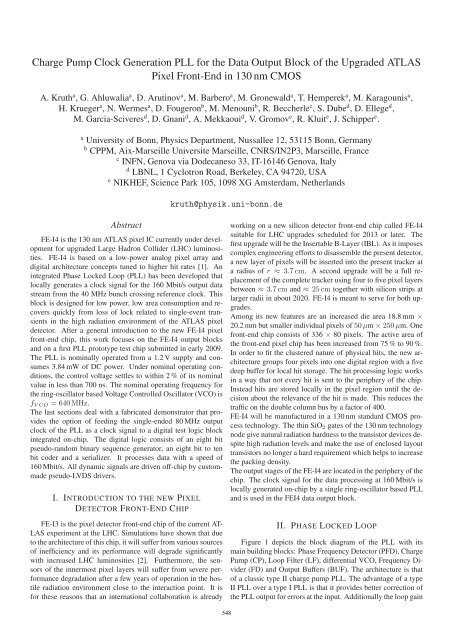
<strong>Charge</strong> <strong>Pump</strong> <strong>Clock</strong> <strong>Generation</strong> <strong>PLL</strong> <strong>for</strong> <strong>the</strong> <strong>Data</strong> <strong>Output</strong> <strong>Block</strong> <strong>of</strong> <strong>the</strong> Upgraded ATLAS<br />
Pixel Front-End in 130 nm CMOS<br />
A. Kruth a , G. Ahluwalia a , D. Arutinov a , M. Barbero a , M. Gronewald a , T. Hemperek a , M. Karagounis a ,<br />
H. Krueger a , N. Wermes a , D. Fougeron b , M. Menouni b , R. Beccherle c , S. Dube d , D. Ellege d ,<br />
M. Garcia-Sciveres d , D. Gnani d , A. Mekkaoui d , V. Gromov e , R. Kluit e , J. Schipper e .<br />
a University <strong>of</strong> Bonn, Physics Department, Nussallee 12, 53115 Bonn, Germany<br />
b CPPM, Aix-Marseille Universite Marseille, CNRS/IN2P3, Marseille, France<br />
c INFN, Genova via Dodecaneso 33, IT-16146 Genova, Italy<br />
d LBNL, 1 Cyclotron Road, Berkeley, CA 94720, USA<br />
e NIKHEF, Science Park 105, 1098 XG Amsterdam, Ne<strong>the</strong>rlands<br />
kruth@physik.uni-bonn.de<br />
Abstract<br />
FE-I4 is <strong>the</strong> 130 nm ATLAS pixel IC currently under development<br />
<strong>for</strong> upgraded Large Hadron Collider (LHC) luminosities.<br />
FE-I4 is based on a low-power analog pixel array and<br />
digital architecture concepts tuned to higher hit rates [1]. An<br />
integrated Phase Locked Loop (<strong>PLL</strong>) has been developed that<br />
locally generates a clock signal <strong>for</strong> <strong>the</strong> 160 Mbit/s output data<br />
stream from <strong>the</strong> 40 MHz bunch crossing reference clock. This<br />
block is designed <strong>for</strong> low power, low area consumption and recovers<br />
quickly from loss <strong>of</strong> lock related to single-event transients<br />
in <strong>the</strong> high radiation environment <strong>of</strong> <strong>the</strong> ATLAS pixel<br />
detector. After a general introduction to <strong>the</strong> new FE-I4 pixel<br />
front-end chip, this work focuses on <strong>the</strong> FE-I4 output blocks<br />
and on a first <strong>PLL</strong> prototype test chip submitted in early 2009.<br />
The <strong>PLL</strong> is nominally operated from a 1.2 V supply and consumes<br />
3.84 mW <strong>of</strong> DC power. Under nominal operating conditions,<br />
<strong>the</strong> control voltage settles to within 2 % <strong>of</strong> its nominal<br />
value in less than 700 ns. The nominal operating frequency <strong>for</strong><br />
<strong>the</strong> ring-oscillator based Voltage Controlled Oscillator (VCO) is<br />
f VCO = 640 MHz.<br />
The last sections deal with a fabricated demonstrator that provides<br />
<strong>the</strong> option <strong>of</strong> feeding <strong>the</strong> single-ended 80 MHz output<br />
clock <strong>of</strong> <strong>the</strong> <strong>PLL</strong> as a clock signal to a digital test logic block<br />
integrated on-chip. The digital logic consists <strong>of</strong> an eight bit<br />
pseudo-random binary sequence generator, an eight bit to ten<br />
bit coder and a serializer. It processes data with a speed <strong>of</strong><br />
160 Mbit/s. All dynamic signals are driven <strong>of</strong>f-chip by custommade<br />
pseudo-LVDS drivers.<br />
I. INTRODUCTION TO THE NEW PIXEL<br />
DETECTOR FRONT-END CHIP<br />
FE-I3 is <strong>the</strong> pixel detector front-end chip <strong>of</strong> <strong>the</strong> current AT-<br />
LAS experiment at <strong>the</strong> LHC. Simulations have shown that due<br />
to <strong>the</strong> architecture <strong>of</strong> this chip, it will suffer from various sources<br />
<strong>of</strong> inefficiency and its per<strong>for</strong>mance will degrade significantly<br />
with increased LHC luminosities [2]. Fur<strong>the</strong>rmore, <strong>the</strong> sensors<br />
<strong>of</strong> <strong>the</strong> innermost pixel layers will suffer from severe per<strong>for</strong>mance<br />
degradation after a few years <strong>of</strong> operation in <strong>the</strong> hostile<br />
radiation environment close to <strong>the</strong> interaction point. It is<br />
<strong>for</strong> <strong>the</strong>se reasons that an international collaboration is already<br />
working on a new silicon detector front-end chip called FE-I4<br />
suitable <strong>for</strong> LHC upgrades scheduled <strong>for</strong> 2013 or later. The<br />
first upgrade will be <strong>the</strong> Insertable B-Layer (IBL). As it imposes<br />
complex engineering ef<strong>for</strong>ts to disassemble <strong>the</strong> present detector,<br />
a new layer <strong>of</strong> pixels will be inserted into <strong>the</strong> present tracker at<br />
a radius <strong>of</strong> r ≈ 3.7cm. A second upgrade will be a full replacement<br />
<strong>of</strong> <strong>the</strong> complete tracker using four to five pixel layers<br />
between ≈ 3.7cm and ≈ 25 cm toge<strong>the</strong>r with silicon strips at<br />
larger radii in about 2020. FE-I4 is meant to serve <strong>for</strong> both upgrades.<br />
Among its new features are an increased die area 18.8 mm ×<br />
20.2 mm but smaller individual pixels <strong>of</strong> 50 μm × 250 μm. One<br />
front-end chip consists <strong>of</strong> 336 × 80 pixels. The active area <strong>of</strong><br />
<strong>the</strong> front-end pixel chip has been increased from 75 % to 90 %.<br />
In order to fit <strong>the</strong> clustered nature <strong>of</strong> physical hits, <strong>the</strong> new architecture<br />
groups four pixels into one digital region with a five<br />
deep buffer <strong>for</strong> local hit storage. The hit processing logic works<br />
in a way that not every hit is sent to <strong>the</strong> periphery <strong>of</strong> <strong>the</strong> chip.<br />
Instead hits are stored locally in <strong>the</strong> pixel region until <strong>the</strong> decision<br />
about <strong>the</strong> relevance <strong>of</strong> <strong>the</strong> hit is made. This reduces <strong>the</strong><br />
traffic on <strong>the</strong> double column bus by a factor <strong>of</strong> 400.<br />
FE-I4 will be manufactured in a 130 nm standard CMOS process<br />
technology. The thin SiO 2 gates <strong>of</strong> <strong>the</strong> 130 nm technology<br />
node give natural radiation hardness to <strong>the</strong> transistor devices despite<br />
high radiation levels and make <strong>the</strong> use <strong>of</strong> enclosed layout<br />
transistors no longer a hard requirement which helps to increase<br />
<strong>the</strong> packing density.<br />
The output stages <strong>of</strong> <strong>the</strong> FE-I4 are located in <strong>the</strong> periphery <strong>of</strong> <strong>the</strong><br />
chip. The clock signal <strong>for</strong> <strong>the</strong> data processing at 160 Mbit/s is<br />
locally generated on-chip by a single ring-oscillator based <strong>PLL</strong><br />
and is used in <strong>the</strong> FEI4 data output block.<br />
II. PHASE LOCKED LOOP<br />
Figure 1 depicts <strong>the</strong> block diagram <strong>of</strong> <strong>the</strong> <strong>PLL</strong> with its<br />
main building blocks: Phase Frequency Detector (PFD), <strong>Charge</strong><br />
<strong>Pump</strong> (CP), Loop Filter (LF), differential VCO, Frequency Divider<br />
(FD) and <strong>Output</strong> Buffers (BUF). The architecture is that<br />
<strong>of</strong> a classic type II charge pump <strong>PLL</strong>. The advantage <strong>of</strong> a type<br />
II <strong>PLL</strong> over a type I <strong>PLL</strong> is that it provides better correction <strong>of</strong><br />
<strong>the</strong> <strong>PLL</strong> output <strong>for</strong> errors at <strong>the</strong> input. Additionally <strong>the</strong> loop gain<br />
548
and stability properties are set independent <strong>of</strong> each o<strong>the</strong>r and <strong>the</strong><br />
PFD <strong>of</strong> a type II <strong>PLL</strong> does not only detect phase mismatch but<br />
also frequency mismatch [3].<br />
ffb<br />
f ref =40MHz<br />
Fb2Fast<br />
PFD<br />
Ref2Fast<br />
f out = 40 MHz<br />
UP<br />
DN<br />
CP<br />
LF<br />
3rd order<br />
V CTRL<br />
:2 :2 :2 :2<br />
80 MHz<br />
160 MHz<br />
320 MHz<br />
VCO<br />
640 MHz<br />
Figure 1: Schematic block diagram <strong>of</strong> <strong>the</strong> <strong>PLL</strong>.<br />
fVCO =16· fref<br />
<strong>the</strong> f REF reference clock signal Ref2Fast- delayed by a certain<br />
time T . This delay time T determines <strong>the</strong> sensitivity <strong>of</strong> <strong>the</strong> loss<br />
<strong>of</strong> lock detection. A loss <strong>of</strong> lock resulting in DN = high -resp.<br />
UP = high- <strong>for</strong> longer than T (neglecting <strong>the</strong> propagation delay<br />
<strong>of</strong> a D-flipflop) will cause <strong>the</strong> signal Fb2Fast -resp. <strong>the</strong> signal<br />
Ref2Fast- to go high indicating severe changes in V CTRL . The<br />
value <strong>for</strong> T has to be chosen large enough in order to prevent<br />
<strong>the</strong> loss <strong>of</strong> lock detection signals to go permanently high due to<br />
process variations.<br />
f REF<br />
f FB<br />
D<br />
D<br />
R<br />
R<br />
T<br />
Q<br />
Q<br />
T<br />
D<br />
&<br />
Q<br />
Ref2Fast<br />
UP<br />
DN<br />
D Q<br />
Fb2Fast<br />
The nominal VCO oscillation frequency is f VCO =<br />
640 MHz. At <strong>the</strong> time <strong>the</strong> design <strong>of</strong> <strong>the</strong> <strong>PLL</strong> started, it had<br />
not been decided whe<strong>the</strong>r <strong>the</strong> 160 Mbit/s front-end output data<br />
will be processed at 160 MHz single-edge or 80 MHz double<br />
edge. The <strong>PLL</strong> prototype can provide both clock frequencies<br />
derived from f VCO . Besides, <strong>the</strong> choice <strong>of</strong> a higher frequency<br />
f VCO eases <strong>the</strong> task <strong>of</strong> generating lower frequency outputs with<br />
a clean 50 % duty cycle required <strong>for</strong> double edge data processing.<br />
Fur<strong>the</strong>rmore, <strong>the</strong> physical dimensions <strong>of</strong> <strong>the</strong> capacitive elements<br />
required in <strong>the</strong> LF are smaller (cf. Eq. 1) and <strong>the</strong> devices<br />
consume less die area. This enables an on-chip integration <strong>of</strong> <strong>the</strong><br />
complete LF without external components. Due to synergy with<br />
o<strong>the</strong>r projects, <strong>the</strong> <strong>PLL</strong> also provides higher frequency clocks<br />
at f OUT = 320 MHz and f OUT = 640 MHz. The mentioned<br />
benefits come at <strong>the</strong> price <strong>of</strong> a slightly increased power consumption<br />
<strong>for</strong> <strong>the</strong> VCO and <strong>the</strong> high frequency divider stages.<br />
The <strong>PLL</strong> will be located in <strong>the</strong> periphery <strong>of</strong> <strong>the</strong> FE-I4 chip and<br />
<strong>the</strong> increased power consumption <strong>of</strong> a single <strong>PLL</strong> on <strong>the</strong> chip is<br />
negligible compared to <strong>the</strong> overall power budget.<br />
The loop transfer function (neglecting higher order terms) is<br />
H(s) = I CPK VCO<br />
2πC notch<br />
1+sR notch C notch<br />
s 2 + s I CP K VCO R notch<br />
2πN<br />
+ I CP K VCO<br />
(1)<br />
2πNC notch<br />
where I CP is <strong>the</strong> charge pump current (cf. Fig. 3), K VCO is<br />
<strong>the</strong> VCO gain, R notch and C notch are loop filter elements (cf.<br />
Fig. 4) and N =16is <strong>the</strong> frequency division factor <strong>of</strong> <strong>the</strong> loop.<br />
A. Phase Frequency Detector and Loss <strong>of</strong> Lock<br />
Detection<br />
The PFD uses a classical architecture with an additional loss<br />
<strong>of</strong> lock detection circuitry (see Fig. 2). The loss <strong>of</strong> lock detection<br />
latches <strong>the</strong> DN signal -resp. UP signal- <strong>of</strong> <strong>the</strong> PFD output<br />
with <strong>the</strong> rising edge <strong>of</strong> <strong>the</strong> f FB signal coming from <strong>the</strong> feedback<br />
branch <strong>of</strong> <strong>the</strong> control loop Fb2Fast -resp. <strong>the</strong> rising edge <strong>of</strong><br />
Figure 2: Schematic <strong>of</strong> <strong>the</strong> phase frequency detector and <strong>the</strong> loss <strong>of</strong><br />
lock detection.<br />
B. <strong>Charge</strong> <strong>Pump</strong><br />
The charge pump uses a differential architecture with a complementary<br />
dummy branch (see Fig. 3). Thus <strong>the</strong> charging and<br />
<strong>the</strong> discharging current source provide an almost constant current<br />
without switching on or <strong>of</strong>f. While <strong>the</strong> main branch is controlled<br />
by <strong>the</strong> UP and <strong>the</strong> DN signal coming from <strong>the</strong> PFD,<br />
<strong>the</strong> complementary branch is controlled by UP and DN. The<br />
inverted signals are delayed by <strong>the</strong> propagation delay <strong>of</strong> <strong>the</strong> inverters<br />
used. The switching transistors M1 to M4 in <strong>the</strong> charge<br />
pump are minimum size devices and thus <strong>the</strong> charge injected<br />
into <strong>the</strong> loop filter upon breaking <strong>the</strong> current path is minimized.<br />
As a consequence spikes on V CTRL due to charge injected from<br />
<strong>the</strong> transistor channels are reduced [4].<br />
UP<br />
R<br />
R<br />
DN<br />
1<br />
I CP<br />
M1<br />
M2<br />
I CP<br />
M3<br />
M4<br />
1<br />
CP OUT<br />
Figure 3: Schematic <strong>of</strong> <strong>the</strong> charge pump with its dummy branch.<br />
549
C. Loop Filter<br />
The first branch <strong>of</strong> <strong>the</strong> LF (cf. Fig. 4) with <strong>the</strong> capacitance<br />
C pole gives a low-pass characteristic to <strong>the</strong> control loop. However,<br />
<strong>the</strong> control loop is unstable with <strong>the</strong> associated frequency<br />
pole. The second branch <strong>of</strong> <strong>the</strong> LF (R notch , C notch ) creates<br />
a frequency notch in order to increase <strong>the</strong> phase margin <strong>of</strong> <strong>the</strong><br />
open-loop transfer function. By a rule <strong>of</strong> thumb 10 × C pole<br />
should be less than C notch in order to ensure sufficient phase<br />
margin. The third branch <strong>of</strong> <strong>the</strong> LF (R ripple ,C ripple ) <strong>for</strong>ms ano<strong>the</strong>r<br />
non-dominant frequency pole that filters high frequency<br />
noise on V CTRL . The characteristic frequency response <strong>of</strong><br />
<strong>the</strong> overall control loop can still be considered a second order<br />
system. The sum <strong>of</strong> all <strong>the</strong> capacitance values in <strong>the</strong> LF is<br />
C SUM ≈ 10 pF. All capacitors are vertical natural caps fully<br />
integrated on chip. The die area consumption <strong>of</strong> <strong>the</strong> <strong>PLL</strong> core is<br />
dominated by <strong>the</strong>se capacitor devices to a large extend.<br />
C pole<br />
R ripple<br />
R notch<br />
C notch<br />
C ripple<br />
Figure 4: Schematic <strong>of</strong> <strong>the</strong> loop filter.<br />
D. Differential Voltage-Controlled Oscillator<br />
The VCO consists <strong>of</strong> three inverters connected as a ring oscillator<br />
and a fourth inverter that serves as a buffer. The inverters<br />
are differential pairs loaded with PFET active loads and<br />
cross-coupled stages <strong>for</strong> rail-to-rail hard switching behavior (see<br />
Fig. 5).<br />
f VCO = 640 MHz is guaranteed <strong>for</strong> 3σ process variations without<br />
additional external tuning. The implemented VCO design is<br />
a trade-<strong>of</strong>f between an extended VCO tuning range and noise<br />
sensitivity.<br />
E. Frequency Dividers and <strong>Output</strong> Buffers<br />
The FDs consist <strong>of</strong> four custom-made divide by two toggleflipflops.<br />
The VCO output frequency <strong>of</strong> f VCO = 640 MHz is<br />
consecutively divided down to 320 MHz, 160 MHz, 80 MHz and<br />
finally to 40 MHz equaling a total frequency division factor <strong>of</strong><br />
N =16.<br />
In <strong>the</strong> output buffering stages, <strong>the</strong> differential clock signals from<br />
<strong>the</strong> dividing chain are converted to single-ended clock signals.<br />
Be<strong>for</strong>e <strong>the</strong> clock signals are sent out <strong>of</strong> <strong>the</strong> chip, <strong>the</strong> lower frequency<br />
clock signals are all gated with <strong>the</strong> 640 MHz clock <strong>for</strong><br />
clock alignment. It is also possible to disable <strong>the</strong> lower frequency<br />
clocks in order to save dynamic power consumption.<br />
The periphery <strong>of</strong> <strong>the</strong> test chip includes silicon proven LVDS<br />
drivers integrated into <strong>the</strong> pads that send <strong>the</strong> dynamic signals<br />
<strong>of</strong>f chip [1].<br />
III. INTEGRATED DIGITAL TEST LOGIC<br />
The digital test logic integrated on <strong>the</strong> fabricated <strong>PLL</strong> test<br />
chip consists <strong>of</strong> an eight bit pseudo random binary sequence<br />
generator, an eight bit ten bit coder and a serializer. The clock<br />
signal <strong>for</strong> <strong>the</strong> test logic can ei<strong>the</strong>r be an external clock or <strong>the</strong><br />
80 MHz single-ended output <strong>of</strong> <strong>the</strong> <strong>PLL</strong> core. The output data<br />
<strong>of</strong> <strong>the</strong> serializer is a 160 Mbit/s double data rate bit stream. The<br />
integration <strong>of</strong> <strong>the</strong> test logic on-chip provides a built-in self-test<br />
<strong>for</strong> <strong>the</strong> <strong>PLL</strong> output signal integrity. The test logic implemented<br />
resembles a large part <strong>of</strong> <strong>the</strong> future FE-I4 data output block.<br />
IV. SIMULATION RESULTS<br />
Figure 6 illustrates <strong>the</strong> settling <strong>of</strong> <strong>the</strong> V CTRL under 3σ process<br />
variations.<br />
1<br />
Out-<br />
Out+<br />
1.0<br />
0.8<br />
T =40 ◦ C, slow corner<br />
T =40 ◦ C, nominal corner<br />
T =40 ◦ C, fast corner<br />
V CTRL<br />
In+<br />
In-<br />
VCTRL [V]<br />
0.6<br />
Figure 5: Schematic <strong>of</strong> a VCO inverter stage.<br />
0.4<br />
The differential architecture guarantees an oscillator with<br />
50 % duty cycle output. Both <strong>the</strong> differential pairs and <strong>the</strong><br />
cross-coupled stages are fed by tail current sources. The control<br />
voltage V CTRL at <strong>the</strong> output <strong>of</strong> <strong>the</strong> LF controls <strong>the</strong> tail current<br />
sources directly whereas <strong>the</strong> PMOS loads are controlled<br />
by <strong>the</strong> inverted V CTRL . As a result <strong>the</strong> oscillator can be tuned<br />
over a wide frequency range and an oscillation frequency <strong>of</strong><br />
0.0 0.3 0.6 0.9 1.2 1.5<br />
Time [μs]<br />
Figure 6: Settling <strong>of</strong> V CTRL with 3σ process variations.<br />
The simulation is based on a parasitic extraction <strong>of</strong> <strong>the</strong> <strong>PLL</strong><br />
core with layout parasitic capacitances included. The <strong>PLL</strong><br />
550
V CTRL settles in less than t settle =1.5 μs in all process corners.<br />
Under nominal conditions V CTRL settles in t settle ≈ 650 ns to<br />
an accuracy <strong>of</strong> 2 % <strong>of</strong> its final value. In order to investigate<br />
<strong>the</strong> <strong>PLL</strong> response to single-event transients, charges <strong>of</strong> 3 pC in<br />
1.5 ns pulses [5] have been injected into various nodes <strong>of</strong> <strong>the</strong><br />
control loop. Figure 7 shows <strong>the</strong> settling <strong>of</strong> V CTRL being interrupted<br />
by a charge injection at t = 900 ns into <strong>the</strong> very same<br />
node that controls <strong>the</strong> oscillation frequency <strong>of</strong> <strong>the</strong> VCO. Fur<strong>the</strong>rmore,<br />
Fig. 7 sketches <strong>the</strong> reaction <strong>of</strong> <strong>the</strong> loss <strong>of</strong> lock detection.<br />
While V CTRL is rising, <strong>the</strong> VCO is oscillating too<br />
slowly. Consequently <strong>the</strong> Ref2Fast signal is high, indicating<br />
that <strong>the</strong> reference clock is too fast resp. f VCO is too low. When<br />
<strong>the</strong> charge injection takes place V CTRL drastically increases,<br />
speeding-up <strong>the</strong> VCO and thus <strong>the</strong> Fb2Fast signal changes to<br />
high, indicating that <strong>the</strong> frequency <strong>of</strong> <strong>the</strong> signal coming from<br />
<strong>the</strong> feedback branch is higher than <strong>the</strong> input reference clock signal.<br />
<strong>Output</strong><br />
Connectors<br />
<strong>PLL</strong><br />
Chip<br />
LVDS<br />
Transceiver<br />
SMA<br />
Connector<br />
Power Connector Jumpers<br />
EN− Potentiometer<br />
Trim<br />
1.2<br />
1.0<br />
V CTRL<br />
Fb2Fast<br />
Ref2Fast<br />
Figure 8: Test PCB designed <strong>for</strong> measurements on <strong>the</strong> <strong>PLL</strong> demonstrator.<br />
Voltage [V]<br />
0.8<br />
0.6<br />
0.4<br />
0.2<br />
0.0<br />
0.0 0.3 0.6 0.9 1.2 1.5<br />
Time [μs]<br />
Figure 7: <strong>PLL</strong> response to a 3 pC charge injection at t = 900 ns onto<br />
<strong>the</strong> node that holds V CTRL.<br />
From noise simulations <strong>the</strong> VCO phase noise is<br />
−83.3 dBc/Hz @ 1 MHz <strong>of</strong>fset and <strong>the</strong> noise is dominated by<br />
flicker noise <strong>of</strong> <strong>the</strong> bias current sources. The phase noise can<br />
be significantly improved to −90.0 dBc/Hz @ 1 MHz <strong>of</strong>fset by<br />
enlarging <strong>the</strong> area <strong>of</strong> <strong>the</strong> devices in <strong>the</strong>se bias circuits. The<br />
enlargement <strong>of</strong> <strong>the</strong>se devices does not affect <strong>the</strong> total die area<br />
consumption <strong>of</strong> <strong>the</strong> <strong>PLL</strong> core and will be incorporated in future<br />
designs.<br />
V. MEASUREMENT RESULTS<br />
Figure 8 shows <strong>the</strong> PCB designed <strong>for</strong> <strong>the</strong> measurements <strong>of</strong><br />
<strong>the</strong> <strong>PLL</strong> demonstrator. The trim potentiometers on <strong>the</strong> right allow<br />
<strong>for</strong> a flexible adjustment <strong>of</strong> bias currents and voltages. The<br />
input reference clock is fed to <strong>the</strong> SMA connector at <strong>the</strong> bottom.<br />
Next to <strong>the</strong> SMA connector on <strong>the</strong> right, jumpers can be<br />
used to enable or disable <strong>the</strong> different outputs <strong>of</strong> <strong>the</strong> test chip.<br />
The connection points <strong>for</strong> <strong>the</strong> probe heads are located at <strong>the</strong> top.<br />
The demonstrator itself is bonded onto <strong>the</strong> PCB close to a custom<br />
made LVDS transceiver chip that is also bonded onto <strong>the</strong><br />
PCB in between <strong>the</strong> SMA connector and <strong>the</strong> connectors <strong>for</strong> <strong>the</strong><br />
probes.<br />
For all measurements, <strong>the</strong> input reference clock has been<br />
supplied by an Agilent 81134A pulser with a jitter rms <strong>of</strong> 2 ps<br />
according to <strong>the</strong> data sheet. The oscilloscope used in <strong>the</strong> measurements<br />
is a Tektronix TDS5104B 5 GS/s, 1 GHz scope with<br />
active differential probes <strong>of</strong> 1 GHz bandwidth. The equipment<br />
used limits <strong>the</strong> measurement accuracy <strong>for</strong> signals with frequencies<br />
higher than 160 MHz. However, it needs to be kept in<br />
mind that <strong>the</strong> lower frequency clocks are internally generated<br />
from <strong>the</strong> higher frequency clocks. Thus <strong>the</strong> encouraging results<br />
<strong>for</strong> <strong>the</strong> lower frequency clocks indicate well functioning<br />
higher frequency clocks. As <strong>the</strong> output clock measurements are<br />
per<strong>for</strong>med on <strong>the</strong> PCB, <strong>the</strong>se measurements always include <strong>the</strong><br />
per<strong>for</strong>mance characteristics <strong>of</strong> <strong>the</strong> LVDS drivers integrated into<br />
<strong>the</strong> output pads <strong>of</strong> <strong>the</strong> test chip.<br />
Table 1 summarizes <strong>the</strong> results obtained <strong>for</strong> <strong>the</strong> <strong>PLL</strong> demonstrator.<br />
The results have been obtained by triggering <strong>the</strong> scope<br />
on one edge and measuring <strong>the</strong> time jitter resp. frequency jitter<br />
on <strong>the</strong> consecutive edge (cycle-to-cycle jitter) with <strong>the</strong> built-in<br />
measurement functions <strong>of</strong> <strong>the</strong> scope. The duty cycle has also<br />
been acquired with <strong>the</strong> measurement functions <strong>of</strong> <strong>the</strong> scope.<br />
Table 1: Measurement data <strong>for</strong> <strong>the</strong> <strong>PLL</strong> operated from a 1.2 V supply.<br />
Equipm.<br />
<strong>PLL</strong><br />
Test<br />
Frequency 40 40 80 160 320 640<br />
[MHz]<br />
Jitter pk-pk 44 82 74 94 70 106<br />
[ps]<br />
σ-Frequency 6.5 19 79 258 1710 8100<br />
[kHz]<br />
σ-Period [ps] 4.1 12 12 11 17 20<br />
Duty Cycle x 0.24 0.33 0.10 x x<br />
Deviation [%]<br />
Figure 9 shows <strong>the</strong> eye diagram <strong>of</strong> a 160 Mbit/s data stream<br />
551
sent out by <strong>the</strong> digital test block. The test logic uses <strong>the</strong> chip internal<br />
single-ended 80 MHz clock output <strong>of</strong> <strong>the</strong> <strong>PLL</strong> core. The<br />
shift <strong>of</strong> <strong>the</strong> crossing points indicates a deviation <strong>of</strong> <strong>the</strong> duty cycle<br />
from <strong>the</strong> ideal 50 %. The deviation is attributed to an asymmetry<br />
in <strong>the</strong> circuits behaviour outside <strong>the</strong> <strong>PLL</strong> core.<br />
>6.0 ns<br />
284 mV<br />
Figure 9: 160 Mbit/s serialized output data stream <strong>of</strong> <strong>the</strong> on-chip digital<br />
test logic using <strong>the</strong> <strong>PLL</strong> 80 MHz clock output.<br />
The opening <strong>of</strong> <strong>the</strong> eye diagram is ≥6.0 ns on <strong>the</strong> time axis<br />
and 284 mV on <strong>the</strong> voltage axis. The reduction <strong>of</strong> signal level<br />
on <strong>the</strong> voltage axis is not related to <strong>the</strong> <strong>PLL</strong> characteristics but<br />
to signal overshoot due to <strong>of</strong>f-chip impedance mismatch.<br />
The tracking range <strong>of</strong> <strong>the</strong> VCO is 336 MHz ≤ f VCO ≤<br />
976 MHz. Outside <strong>of</strong> this range <strong>the</strong> Fb2Fast -resp. Ref2Fastsignals<br />
go to permanent high.<br />
VI. CONCLUSION<br />
A new ATLAS Front-End chip FE-I4 is being developed in<br />
a 130 nm standard CMOS technology <strong>for</strong> use <strong>for</strong> upgraded LHC<br />
luminosities, both <strong>for</strong> <strong>the</strong> Insertable B-Layer project and Super-<br />
LHC. FE-I4 is based on a low-power analog pixel array and<br />
new digital architecture concepts. After a short introduction to<br />
<strong>the</strong> new features <strong>of</strong> <strong>the</strong> FE-I4 chip, <strong>the</strong> focus is on <strong>the</strong> output<br />
stages. In order to handle <strong>the</strong> expected hit rate, <strong>the</strong> front-end<br />
will stream data out at 160 Mbit/s. A type-II <strong>PLL</strong> has been<br />
developed to generate <strong>the</strong> necessary clock signal with a welldefined<br />
duty cycle from <strong>the</strong> available 40 MHz bunch crossing<br />
reference clock. The <strong>PLL</strong> core draws a low current <strong>of</strong> 3.2 mA<br />
from a 1.2 V supply and consumes a die area <strong>of</strong> only 255 μm ×<br />
225 μm. The VCO <strong>of</strong> <strong>the</strong> <strong>PLL</strong> is based on a three-stage differential<br />
ring oscillator working at a nominal frequency <strong>of</strong> 640 MHz.<br />
The design trade-<strong>of</strong>fs involved with <strong>the</strong> choice <strong>of</strong> a ring oscillator<br />
in terms <strong>of</strong> area, noise and locking range are discussed.<br />
Choosing an oscillation frequency higher than <strong>the</strong> output frequency<br />
<strong>for</strong> <strong>the</strong> VCO guarantees a lower area consumption <strong>of</strong><br />
<strong>the</strong> LF capacitors and a well-defined duty cycle handling at <strong>the</strong><br />
expense <strong>of</strong> slightly increased power consumption <strong>for</strong> <strong>the</strong> VCO<br />
and <strong>the</strong> four-stage dividing chain. In <strong>the</strong> ATLAS experiment,<br />
<strong>the</strong> <strong>PLL</strong> will be placed in a hostile radiation environment. In<br />
case <strong>of</strong> single-event transients due to severe charge injections, a<br />
short settling time to recover from a loss <strong>of</strong> lock is important.<br />
The presented <strong>PLL</strong> recovers from any given upset in less than<br />
1.5 μs.<br />
A stand-alone <strong>PLL</strong> test chip has been submitted <strong>for</strong> fabrication<br />
early in 2009. Among its outputs are clock signals with 80 MHz<br />
<strong>for</strong> double edge data transfer and 160 MHz <strong>for</strong> single edge data<br />
stream out at 160 Mbit/s. The differential clock output lines are<br />
driven by integrated LVDS drivers. Simulation results as well as<br />
per<strong>for</strong>mance measurements <strong>for</strong> this test chip are presented and<br />
discussed.<br />
The <strong>PLL</strong> is equipped with on-chip loss-<strong>of</strong>-lock detection circuits.<br />
Fur<strong>the</strong>rmore, <strong>the</strong> demonstrator includes a digital block<br />
<strong>for</strong> 160 Mbit/s double data rate output streaming, consisting <strong>of</strong><br />
an eight bit pseudo random binary sequence generator, an eight<br />
bit to ten bit coder and a serializer. The integrity <strong>of</strong> <strong>the</strong> serialized<br />
160 Mbit/s double data rate bit stream generated by <strong>the</strong> test<br />
logic has been investigated and has been found acceptable.The<br />
first prototype <strong>of</strong> <strong>the</strong> complete FE-I4 IC is scheduled <strong>for</strong> tape<br />
out at <strong>the</strong> end <strong>of</strong> 2009.<br />
REFERENCES<br />
[1] M. Karagounis et al., Development <strong>of</strong> <strong>the</strong> ATLAS FE-<br />
I4 pixel readout IC <strong>for</strong> b-layer Upgrade and Super-LHC,<br />
TWEPP’08, 2008, pp.70-75.<br />
[2] D. Arutinov et al., Digital Architecture and Interface <strong>of</strong> <strong>the</strong><br />
new ATLAS Pixel Front-End IC <strong>for</strong> Upgraded LHC Luminosity,<br />
IEEE Transactions on Nuclear Science, Vol.56,<br />
No.2, 2009<br />
[3] B. Razavi, RF Microelectronics, Prentice Hall PTR, ISBN<br />
0-13-887571-5, 1998.<br />
[4] S. Cheng et al., Design and Analysis <strong>of</strong> an Ultrahigh-<br />
Speed Glitch-Free Fully Differential <strong>Charge</strong> <strong>Pump</strong> With<br />
Minimum <strong>Output</strong> Current Variation and Accurate Matching,<br />
IEEE Transactions on Circuits and Systems-II: Express<br />
Briefs, Vol.53, No.9, 2006.<br />
[5] L. Wang et al., An SEU-Tolerant Programmable Frequency<br />
Divider, Proceedings <strong>of</strong> ISQED’07.<br />
552