Computational Mechanics Research and Support for Aerodynamics ...
Computational Mechanics Research and Support for Aerodynamics ...
Computational Mechanics Research and Support for Aerodynamics ...
- No tags were found...

You also want an ePaper? Increase the reach of your titles
YUMPU automatically turns print PDFs into web optimized ePapers that Google loves.
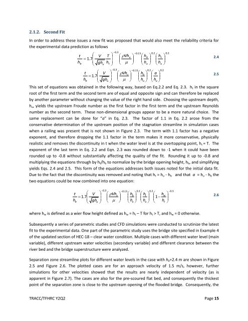
2.1.2. Second Fit<br />
In order to address these issues a new fit was proposed that would also meet the reliability criteria <strong>for</strong><br />
the experimental data prediction as follows<br />
t<br />
h<br />
b<br />
<br />
1.<br />
7<br />
<br />
<br />
V<br />
gh<br />
u<br />
T<br />
h<br />
t<br />
<br />
<br />
<br />
<br />
0.<br />
3<br />
0.<br />
3<br />
<br />
<br />
<br />
0.<br />
15 0.<br />
2 0.<br />
2<br />
Vhu<br />
hb<br />
ht<br />
<br />
2.4<br />
<br />
<br />
<br />
<br />
h<br />
u<br />
<br />
<br />
<br />
h<br />
u<br />
<br />
<br />
0.<br />
15 0.<br />
2 0.<br />
2<br />
Vhu<br />
h <br />
b a <br />
2.5<br />
t V <br />
1.<br />
7<br />
<br />
h<br />
b gh<br />
u<br />
h<br />
u h<br />
u <br />
This set of equations was obtained in the following way, based on Eq.2.2 <strong>and</strong> Eq. 2.3. h t in the square<br />
root of the first term <strong>and</strong> the second term are of equal <strong>and</strong> opposite sign <strong>and</strong> can there<strong>for</strong>e be replaced<br />
by another parameter without changing the value of the right h<strong>and</strong> side. Choosing the upstream depth,<br />
h u , yields the upstream Froude number as the first factor in the first term <strong>and</strong> the upstream Reynolds<br />
number as the second term. These non-dimensional groups appear to be a more natural choice. The<br />
same replacement can be done <strong>for</strong> “a” in Eq. 2.3. The factor of 1.1 in Eq. 2.2 arose from the<br />
conservative determination of the upstream position of the stagnation streamline in simulation cases<br />
when a railing was present that is not shown in Figure 2.3. The term with 1.1 factor has a negative<br />
exponent, <strong>and</strong> there<strong>for</strong>e dropping the 1.1 factor in the term makes it more conservative, physically<br />
realistic <strong>and</strong> removes the discontinuity in t when the water level is at the overtopping point, h t = T. The<br />
exponent of the last term in Eq. 2.2 <strong>and</strong> Eqn. 2.3 was rounded down to -1 when it could have been<br />
rounded up to -0.8 without substantially affecting the quality of the fit. Rounding it up to -0.8 <strong>and</strong><br />
multiplying the equations through by h t /h b to normalize by the bridge opening height, h b , <strong>and</strong> simplifying<br />
yields Eqs. 2.4 <strong>and</strong> 2.5. This <strong>for</strong>m of the equations addresses both issues noted <strong>for</strong> the initial data fit.<br />
Due to the fact that the discontinuity was removed <strong>and</strong> noting that h t = h u - h b <strong>and</strong> that a = h u - h b the<br />
two equations could be now combined into one equation:<br />
t<br />
h<br />
b<br />
<br />
1.<br />
7<br />
<br />
V<br />
gh<br />
u<br />
<br />
<br />
<br />
0.<br />
3<br />
0.<br />
15<br />
0.<br />
2<br />
0.<br />
2<br />
0.<br />
3<br />
Vhu<br />
h <br />
b h <br />
t h <br />
w<br />
1<br />
<br />
h<br />
u h<br />
<br />
2.6<br />
u h<br />
t <br />
where h w is defined as a wier flow height defined as h w = h t – T <strong>for</strong> h t > T, <strong>and</strong> h w = 0 otherwise.<br />
Subsequently a series of parametric studies <strong>and</strong> CFD simulations were conducted to scrutinize the latest<br />
fit to the experimental data. One part of the parametric study uses the bridge site specified in Example 4<br />
of the updated section of HEC-18 – clear water condition. Multiple cases with different water level (main<br />
variable), different upstream water velocities (secondary variable) <strong>and</strong> different clearance between the<br />
river bed <strong>and</strong> the bridge superstructure were analyzed.<br />
Separation zone streamline plots <strong>for</strong> different water levels in the case with h b =2.4 m are shown in Figure<br />
2.5 <strong>and</strong> Figure 2.6. The plotted cases are <strong>for</strong> an approach velocity of 1.5 m/s, however, further<br />
simulations <strong>for</strong> other velocities showed that the results are nearly independent of velocity (as is<br />
apparent in Figure 2.7). The cases are also <strong>for</strong> the pre-scoured flat bed, <strong>and</strong> consequently the thickest<br />
point of the separation zone is close to the upstream opening of the flooded bridge. Consequently, the<br />
TRACC/TFHRC Y2Q2 Page 15