Computational Mechanics Research and Support for Aerodynamics ...
Computational Mechanics Research and Support for Aerodynamics ...
Computational Mechanics Research and Support for Aerodynamics ...
- No tags were found...

Create successful ePaper yourself
Turn your PDF publications into a flip-book with our unique Google optimized e-Paper software.
extend the impact of the findings to a greater variety of culvert geometry <strong>and</strong> flow conditions with good<br />
confidence.<br />
2.3.1.1. Comparison of CFD results with experimental data<br />
The hydraulic flume used <strong>for</strong> testing culverts in the fish passage study had a width the same as the<br />
radius of the selected culvert pipe. It was there<strong>for</strong>e possible to fit an entire quarter of the pipe into the<br />
flume widthwise. The quarter-pipe setup allowed optimal visibility to the flow through the translucent<br />
flume wall <strong>for</strong> the access of laser light sheet <strong>and</strong> camera that were required by PIV.<br />
The primary validation ef<strong>for</strong>t consisted of a comparison of model predictions of velocity distribution<br />
from the STAR-CCM+ software against experimental data under various average velocities, flow depths,<br />
<strong>and</strong> gravel bed elevations. Analyses were conducted to quantify discrepancies between CFD output <strong>and</strong><br />
experimentally measured values, <strong>and</strong> to assess how these discrepancies affect the qualification of a<br />
culvert as fish passable.<br />
As mentioned in previous reports, test scenarios per<strong>for</strong>med in the physical modeling included three<br />
different water depths, two velocities, <strong>and</strong> three bed elevations. CFD models <strong>for</strong> the calibration process<br />
were created precisely following the geometry of the physical models. Single-phase models with cyclic<br />
boundary conditions were used. Validation work presented in previous reports showed good agreement<br />
between uni<strong>for</strong>m flow results from this highly efficient approach <strong>and</strong> those from time-consuming fullbarrel<br />
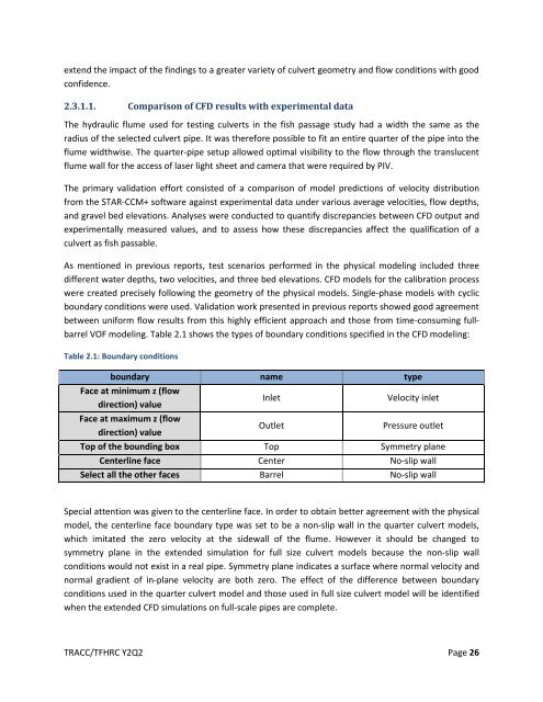
VOF modeling. Table 2.1 shows the types of boundary conditions specified in the CFD modeling:<br />
Table 2.1: Boundary conditions<br />
boundary name type<br />
Face at minimum z (flow<br />
direction) value<br />
Face at maximum z (flow<br />
direction) value<br />
Inlet<br />
Outlet<br />
Velocity inlet<br />
Pressure outlet<br />
Top of the bounding box Top Symmetry plane<br />
Centerline face Center No-slip wall<br />
Select all the other faces Barrel No-slip wall<br />
Special attention was given to the centerline face. In order to obtain better agreement with the physical<br />
model, the centerline face boundary type was set to be a non-slip wall in the quarter culvert models,<br />
which imitated the zero velocity at the sidewall of the flume. However it should be changed to<br />
symmetry plane in the extended simulation <strong>for</strong> full size culvert models because the non-slip wall<br />
conditions would not exist in a real pipe. Symmetry plane indicates a surface where normal velocity <strong>and</strong><br />
normal gradient of in-plane velocity are both zero. The effect of the difference between boundary<br />
conditions used in the quarter culvert model <strong>and</strong> those used in full size culvert model will be identified<br />
when the extended CFD simulations on full-scale pipes are complete.<br />
TRACC/TFHRC Y2Q2 Page 26