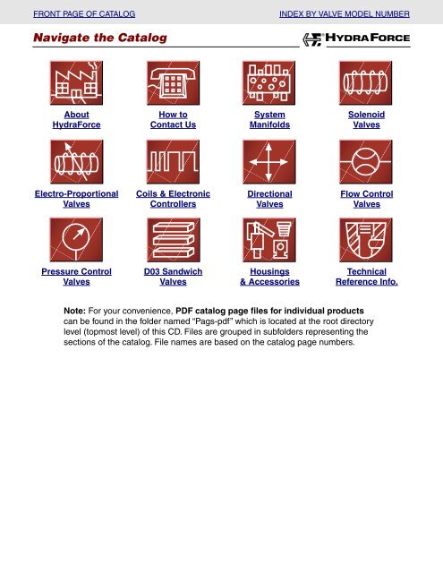
Navigate the Catalog HYDRAFORCE
Navigate the Catalog HYDRAFORCE
Navigate the Catalog HYDRAFORCE
- No tags were found...

Create successful ePaper yourself
Turn your PDF publications into a flip-book with our unique Google optimized e-Paper software.
FRONT PAGE OF CATALOG<br />
<strong>Navigate</strong> <strong>the</strong> <strong>Catalog</strong><br />
INDEX BY VALVE MODEL NUMBER<br />
®<br />
<strong>HYDRAFORCE</strong><br />
About<br />
HydraForce<br />
How to<br />
Contact Us<br />
System<br />
Manifolds<br />
Solenoid<br />
Valves<br />
Electro-Proportional<br />
Valves<br />
Coils & Electronic<br />
Controllers<br />
Directional<br />
Valves<br />
Flow Control<br />
Valves<br />
Pressure Control<br />
Valves<br />
D03 Sandwich<br />
Valves<br />
Housings<br />
& Accessories<br />
Technical<br />
Reference Info.<br />
Note: For your convenience, PDF catalog page files for individual products<br />
can be found in <strong>the</strong> folder named “Pags-pdf” which is located at <strong>the</strong> root directory<br />
level (topmost level) of this CD. Files are grouped in subfolders representing <strong>the</strong><br />
sections of <strong>the</strong> catalog. File names are based on <strong>the</strong> catalog page numbers.
COILS AND ELECTRONIC CONTROLS<br />
Standard Coils and Proportional Valve Coils<br />
WHY <strong>HYDRAFORCE</strong> STANDARD COILS OUTPERFORM COMPETITIVE UNITS<br />
High Quality Materials<br />
HydraForce coils are made with<br />
high quality, Class H magnetwire<br />
and insulation materials.<br />
More Ampere Turns<br />
More copper wire turns deliver more<br />
magnetic flux per current input.<br />
Rugged Casing<br />
Coils are housed in a durable 30%<br />
glass-filled <strong>the</strong>rmoplastic casing,<br />
providing a rigid base for coil<br />
terminations.<br />
Superior Frame Density<br />
Thick iron surrounds <strong>the</strong><br />
copper winding, increasing<br />
<strong>the</strong> coil’s flux density and<br />
<strong>the</strong>refore its power as an<br />
electromagnet.<br />
Multiple Termination<br />
Options<br />
HydraForce offers many<br />
standard types of electrical<br />
connections, and will<br />
consider OEM requests<br />
for special terminations.<br />
DC Windings<br />
All windings are DC. AC service coils<br />
are internally full-wave-rectified, so<br />
cartridges are voltage-interchangeable<br />
and do not exhibit AC “buzz” or suffer<br />
burn-out due to partial armature shift.<br />
HydraForce DC coils are UL Listed<br />
under File #AU2326.<br />
Custom Coils<br />
HydraForce can provide windings<br />
precisely-tailored for special OEM<br />
applications. Some of <strong>the</strong> common<br />
windings are listed on <strong>the</strong> following<br />
page; consult <strong>the</strong> factory if <strong>the</strong>se do<br />
not meet your requirements.<br />
Heat Rise<br />
Ra<strong>the</strong>r than using heat sinks or<br />
external cooling methods,<br />
HydraForce uses larger coils for<br />
lower heat rise, stronger electromagnetic<br />
force and longer coil life.<br />
HydraForce coils can be operated<br />
continuously at ambient temperatures<br />
to 100°C without challenging<br />
<strong>the</strong> coil’s insulation system.<br />
Note: Some coils may differ in construction from this illustration.<br />
3.200.1
COMMON WINDING SPECIFICATIONS<br />
®<br />
<strong>HYDRAFORCE</strong><br />
Standard Coils and Proportional Valve Coils<br />
Volts<br />
6*<br />
10<br />
12<br />
20*<br />
24<br />
30*<br />
36<br />
48<br />
72*<br />
110<br />
24<br />
115<br />
230<br />
08, 80 Size Coil Data<br />
(14.7 Watts)<br />
Resistance<br />
(DC) @ 20°C<br />
Ohms<br />
*Special Order Coils<br />
DC Service<br />
2.46<br />
6.8<br />
9.8<br />
27.2<br />
39.3<br />
61.4<br />
88.3<br />
156.6<br />
352.4<br />
823.1<br />
AC Service<br />
31.2<br />
765.5<br />
3035.0<br />
Initial<br />
Current Draw<br />
Amps<br />
2.44<br />
1.47<br />
1.22<br />
0.74<br />
0.61<br />
0.49<br />
0.41<br />
0.31<br />
0.20<br />
0.13<br />
0.61<br />
0.13<br />
0.06<br />
10, 38, 58, 12, 52, 16, 56 Size<br />
Coil Data (20 Watts)<br />
Volts<br />
6*<br />
10<br />
12<br />
20*<br />
24<br />
30*<br />
36<br />
48<br />
72*<br />
110<br />
24<br />
115<br />
230<br />
Resistance<br />
(DC) @ 20°C<br />
Ohms<br />
DC Service<br />
1.8<br />
4.8<br />
7.2<br />
19.0<br />
28.8<br />
43.2<br />
64.8<br />
110.2<br />
249.8<br />
605.0<br />
AC Service<br />
23.6<br />
568.0<br />
2304.0<br />
*Special Order Coils<br />
Initial<br />
Current Draw<br />
Amps<br />
3.33<br />
2.08<br />
1.67<br />
1.05<br />
0.83<br />
0.69<br />
0.56<br />
0.44<br />
0.29<br />
0.18<br />
0.83<br />
0.17<br />
0.09<br />
Volts<br />
12<br />
24<br />
Volts<br />
10<br />
12<br />
20<br />
24<br />
70 Size Coil Data<br />
Proportional Coil Data<br />
Resistance<br />
(DC) @ 20°C<br />
Ohms<br />
5.0<br />
20.0<br />
Nominal I-Max.<br />
Current Draw<br />
Amps<br />
1.50<br />
0.75<br />
EHPR Coil Data<br />
Proportional Coil Data<br />
Resistance<br />
(DC) @ 20°C<br />
Ohms<br />
3.1<br />
5.4<br />
12.5<br />
21.7<br />
Nominal I-Max.<br />
Current Draw<br />
Amps<br />
1.50<br />
1.20<br />
0.75<br />
0.60<br />
COIL INFORMATION<br />
• AC service coils are internally rectified, and can be used in 50<br />
or 60 cycle (Hz) lines.<br />
• Special voltages and terminations are available for OEM<br />
applications; consult factory.<br />
• Coil should always be installed with lettering facing up.<br />
• Standard coils are not hermetically sealed. For applications<br />
requiring water or wea<strong>the</strong>r resistant coils, see pages<br />
8.250.1-2 and pages 3.400.1-6<br />
• AC voltage service with transient surges over 1000 volts may<br />
require that a varistor be placed in parallel at <strong>the</strong> coil.<br />
Voltage Varistor Part No. Joule Rating Required<br />
GE: V150LA10A<br />
115 Siemens: S10R150 45 minimum<br />
or equivalent<br />
GE: V250LA40A<br />
230 Siemens: S20R250 130 minimum<br />
or equivalent<br />
COIL ACCESSORIES<br />
Coil Ground Strap<br />
for DS Coils<br />
P/N 6502200<br />
DIN 43650<br />
1/2" Conduit to Connector<br />
P/N 6110001<br />
DIN 43650<br />
Cable Gland PG 9<br />
(7 mm nominal cable diameter)<br />
P/N 6110002<br />
or Cable Gland PG 11<br />
(9 mm nominal cable diameter)<br />
P/N 6110005<br />
3.200.2
COILS AND ELECTRONIC CONTROLS<br />
Standard Coils and Proportional Valve Coils<br />
SERIES 08, 80, 88, 98 COIL INFORMATION<br />
S<br />
Dual Spades<br />
SAE J858a<br />
L<br />
Dual Leads<br />
18 Gauge<br />
Optional 36-inch leads<br />
available. Consult factory.<br />
P<br />
1/2" Conduit &<br />
18 Gauge Leads<br />
Part Number Suffix<br />
Voltage S L P<br />
10 VDC<br />
12 VDC<br />
24 VDC<br />
36 VDC<br />
48 VDC<br />
6301010<br />
6301012<br />
6301024<br />
6301036<br />
6301048<br />
6302010<br />
6302012<br />
6302024<br />
6302036<br />
6302048<br />
6305012<br />
6305024<br />
110 VDC<br />
*24 VAC<br />
*115 VAC<br />
*230 VAC<br />
6315024<br />
6315115<br />
6315230<br />
*Rectified<br />
3.200.3
SERIES 08, 80, 88, 98 COIL INFORMATION<br />
®<br />
<strong>HYDRAFORCE</strong><br />
Standard Coils and Proportional Valve Coils<br />
1.43<br />
36.3<br />
G<br />
DIN 43650<br />
Connector<br />
W<br />
Dual 18 Gauge Leads with<br />
Wea<strong>the</strong>r Pack ® Connector<br />
For use with Packard part no. 12015792<br />
male plug<br />
K<br />
Kostal<br />
Connector<br />
DK Coils; U.K.<br />
availability only.<br />
DR<br />
Integral Deutsch<br />
Connector<br />
DR Models without Diode<br />
DR/D Models with Diode<br />
DR/Z Models with Zener Diode<br />
Part Number Suffix<br />
Voltage<br />
10 VDC<br />
12 VDC<br />
24 VDC<br />
36 VDC<br />
48 VDC<br />
110 VDC<br />
*24 VAC<br />
*115 VAC<br />
*230 VAC<br />
*Rectified<br />
G<br />
6306012<br />
6306024<br />
6306036<br />
6306048<br />
6306110<br />
6316024<br />
6316115<br />
6316230<br />
W<br />
6309410<br />
6309412<br />
6309424<br />
6309436<br />
6309448<br />
K<br />
6348812<br />
6348824<br />
DR DR/D DR/Z<br />
4301512 4301872 4301852<br />
4301524 4301874 4301854<br />
3.200.4
COILS AND ELECTRONIC CONTROLS<br />
Standard Coils and Proportional Valve Coils<br />
SERIES 10, 12, 16, 38, 58 COIL INFORMATION<br />
S<br />
Dual Spades<br />
SAE J858a<br />
L<br />
Dual Leads<br />
18 Gauge<br />
Optional 36-inch leads<br />
available. Consult factory.<br />
P<br />
1/2" Conduit &<br />
18 Gauge Leads<br />
Part Number Suffix<br />
Voltage S L P<br />
10 VDC<br />
12 VDC<br />
24 VDC<br />
36 VDC<br />
48 VDC<br />
6351010<br />
6351012<br />
6351024<br />
6351036<br />
6351048<br />
6352010<br />
6352012<br />
6352024<br />
6352036<br />
6352048<br />
6355012<br />
6355024<br />
110 VDC<br />
*24 VAC<br />
*115 VAC<br />
*230 VAC<br />
6365024<br />
6365115<br />
6365230<br />
*Rectified<br />
3.200.5
SERIES 10, 12, 16, 38, 58 COIL INFORMATION<br />
®<br />
<strong>HYDRAFORCE</strong><br />
Standard Coils and Proportional Valve Coils<br />
1.76<br />
44.6<br />
G<br />
DIN 43650<br />
Connector<br />
W<br />
Dual 18 Gauge Leads with<br />
Wea<strong>the</strong>r Pack ® Connector<br />
For use with Packard part no. 12015792<br />
male plug<br />
DR<br />
Integral Deutsch<br />
Connector<br />
DR Models without Diode<br />
DR/D Models with Diode<br />
DR/Z Models with Zener Diode<br />
Voltage<br />
10 VDC<br />
12 VDC<br />
24 VDC<br />
36 VDC<br />
48 VDC<br />
110 VDC<br />
*24 VAC<br />
*115 VAC<br />
*230 VAC<br />
*Rectified<br />
G<br />
6356012<br />
6356024<br />
6356036<br />
6356048<br />
6356110<br />
6366024<br />
6366115<br />
6366230<br />
Part Number Suffix<br />
W DR DR/D DR/Z<br />
6359410<br />
6359412<br />
6359424<br />
6359436<br />
6359448<br />
4301612<br />
4301624<br />
4301892<br />
4301894<br />
4301862<br />
4301864<br />
3.200.6
COILS AND ELECTRONIC CONTROLS<br />
Proportional Valve Coils<br />
SIZE 70 COIL INFORMATION<br />
S<br />
Dual Spades<br />
SAE J858a<br />
L<br />
Dual Leads<br />
18 Gauge<br />
G<br />
DIN 43650<br />
Connector<br />
Voltage<br />
12 VDC<br />
24 VDC<br />
Part Number Suffix<br />
S L G<br />
6507112 6507212 6507612<br />
6507124 6507224 6507624<br />
3.200.7
®<br />
<strong>HYDRAFORCE</strong><br />
Proportional Valve Coils<br />
SERIES EHPR08 COIL INFORMATION<br />
1.19<br />
30.2<br />
0.78<br />
19.9<br />
18.00<br />
457.2<br />
0.78<br />
19.9<br />
1.45<br />
36.8<br />
0.98<br />
24.9<br />
0.78<br />
19.9<br />
9.5<br />
241.3<br />
1.23<br />
31.2<br />
DIA.<br />
1.53<br />
38.9<br />
.050<br />
12.7<br />
INCH<br />
MILLIMETRE<br />
S<br />
Dual Spades<br />
SAE J858a<br />
L<br />
Dual Leads<br />
18 Gauge<br />
Optional 36-inch leads<br />
available. Consult factory.<br />
G<br />
DIN 43650<br />
Connector<br />
W<br />
Dual 18 Gauge Leads with<br />
Wea<strong>the</strong>r Pack ® Connector<br />
For use with Packard part no. 12015792<br />
male plug<br />
Voltage<br />
12 VDC<br />
24 VDC<br />
Part Number Suffix<br />
S L G W<br />
6451112 6451212 6451612 6451512<br />
6451124 6451224 6451624 6451524<br />
3.200.8
COILS AND ELECTRONIC CONTROLS<br />
Standard Coil Wea<strong>the</strong>r-Proofing (obsolete Jan.1, 2002)<br />
INTRODUCTION<br />
For SV Series valves, <strong>the</strong> standard coil wea<strong>the</strong>r-proofing<br />
method described here is being replaced by <strong>the</strong> new<br />
Series E Water/Wea<strong>the</strong>r Resistant Coils described on<br />
pages 3.400.1-7. However, <strong>the</strong> new Series E Coils are not<br />
currently available for most PV, TS or ZL Series Proportional<br />
valves (consult factory). The older method of<br />
wea<strong>the</strong>r-proofing described on <strong>the</strong>se pages will continue<br />
to be available as service parts and for use on existing<br />
applications where coil performance or space limitations<br />
require it.<br />
Standard HydraForce coils are encapsulated and wea<strong>the</strong>rresistant,<br />
having been successfully applied in many mobile<br />
and industrial installations where <strong>the</strong> coil is exposed. However,<br />
<strong>the</strong>se coils are not hermetically sealed against moisture<br />
under all conditions.<br />
Standard HydraForce coils must be protected if both of <strong>the</strong><br />
following conditions apply:<br />
• The coil is run continuously, causing heating of <strong>the</strong> materials<br />
and resultant separation of <strong>the</strong> plastic and metal parts in cooldown<br />
contraction.<br />
• Under <strong>the</strong> above if water is present and can pool at <strong>the</strong> top<br />
or bottom metal washer surface.<br />
Application experience indicates that higher voltage coils are<br />
more susceptible to damage from water due to thin wire<br />
diameters. Extra care should be given to specification for AC<br />
service applications.<br />
WEATHER-PROOFING METHOD<br />
All electrical devices are sensitive to water intrusion and must<br />
be insulated against contact if moisture is present. This is<br />
done by creating a barrier or blocking means to prevent<br />
intimate contact of <strong>the</strong> water and copper.<br />
The HydraForce wea<strong>the</strong>r-proofing system described here<br />
uses external fluorocarbon O-rings positioned and retained at<br />
potential entry points on <strong>the</strong> coil. Various sizes and types of<br />
solenoid cartridges require different installation methods as<br />
illustrated on <strong>the</strong> opposite page. Some of <strong>the</strong>se are retrofitable,<br />
while o<strong>the</strong>rs are not. See <strong>the</strong> table below.<br />
Model Group<br />
PV7x-xx<br />
SL08-22<br />
SL38/58-22<br />
SV08-20, 22, 24, 25, 26, 30, 31, 33,<br />
40, 41, 42, 44, 45, 46<br />
SV08-21, 23<br />
SV08-47A, 47C, 47D<br />
SV10-20, 22, 24, 25, 31, 33, 34,<br />
40, 41, 42, 43, 44, 45<br />
SV10-21, 23<br />
SV10-47A, 47B, 47C, 47D<br />
SV38/58-26<br />
SV58-20, 22, 24, 25, 30, 40, 41, 42, 44<br />
SV58-21, 23<br />
SV12-20, 22<br />
SV12-21, 23<br />
SV16-20, 22<br />
SV16-21, 23<br />
Armature<br />
Type<br />
Proportional<br />
Pull<br />
Pull<br />
Pull<br />
Push<br />
Push/Pull<br />
Pull<br />
Push<br />
Push/Pull<br />
Pull<br />
Pull<br />
Push<br />
Pull<br />
Push<br />
Pull<br />
Push<br />
Installation<br />
Type<br />
E/H<br />
A<br />
A<br />
A<br />
B<br />
C/D<br />
A/F<br />
B/G<br />
C/D<br />
NOTE: Torque wea<strong>the</strong>r-proofing nuts to 0.07–0.10 Nm (7–10 ft. lbs.) max.<br />
A/F<br />
A/F<br />
B<br />
A<br />
B<br />
A<br />
B<br />
Field<br />
Conversion<br />
Yes/All<br />
No<br />
Yes<br />
No<br />
No<br />
Yes/All<br />
No<br />
No<br />
No<br />
No<br />
No<br />
No<br />
Yes/All<br />
Yes/All<br />
Yes/All<br />
Yes/All<br />
Service<br />
Kit P/N<br />
6260145<br />
6260100<br />
6260130<br />
6260100<br />
6260105<br />
C-6260111<br />
D-6260106<br />
A-6260130<br />
F-6260110<br />
B-6260135<br />
G-6260115<br />
C-6260140<br />
D-TBD<br />
A-6260130<br />
F-6260110<br />
A-6260130<br />
F-6260110<br />
6260135<br />
6260130<br />
6260135<br />
6260130<br />
6260135<br />
3.250.1
®<br />
<strong>HYDRAFORCE</strong><br />
Standard Coil Wea<strong>the</strong>r-Proofing (obsolete Jan.1, 2002)<br />
A<br />
SVxx<br />
Pull-Type<br />
B<br />
SVxx<br />
Push-Type<br />
C<br />
SVxx-47<br />
Push/Pull-Type<br />
D<br />
SVxx-47 with Push/Pull<br />
Manual Override<br />
E<br />
PV7x<br />
Proportional<br />
H<br />
PV7x - Proportional<br />
w/Manual Override<br />
3.250.2
COILS AND ELECTRONIC CONTROLS<br />
Series E Environmental Coils<br />
NEW SERIES E WATER-RESISTANT/WEATHER-RESISTANT SOLENOID VALVE COILS<br />
New Series E coils are <strong>the</strong> latest innovation in coil technology<br />
from Hydraforce. They are designed to meet <strong>the</strong> demanding<br />
requirements of mobile and industrial applications where<br />
wea<strong>the</strong>r resistance is required. Models with Deutsch and<br />
Metri-Pack ® integral connectors meet or exceed all IP69K<br />
standards for wea<strong>the</strong>r resistance, offering superior reliability<br />
under <strong>the</strong> most demanding conditions. Series E coils have<br />
passed what is known in <strong>the</strong> construction, agricultural and<br />
mobile equipment markets as <strong>the</strong> “<strong>the</strong>rmal shock dunk test.”<br />
Series E coils feature a new coil winding technology that is<br />
perfect-wound and fully encapsulated. Deutsch and Metri-<br />
Pack ® connectors are molded into <strong>the</strong> coil encapsulation,<br />
assuring IP69K wea<strong>the</strong>r resistance. An external metal shell<br />
serves as <strong>the</strong> element to concentrate <strong>the</strong> magnetic flux for <strong>the</strong><br />
coil winding and also functions as a rugged container for <strong>the</strong><br />
coil. No O-rings or waterproofing kits are required.<br />
Models are available to fit most standard 08, 10, 12, and 16<br />
size valves. In most applications, <strong>the</strong>se coils can be used to<br />
retrofit HydraForce valves already in field operation and will<br />
offer superior wea<strong>the</strong>r resistance.<br />
Thermal Shock Dunk Test Rated<br />
Series E coils with Deutsch and<br />
Metri-Pack ® connectors have<br />
passed what is known in <strong>the</strong><br />
construction, agricultural and<br />
mobile equipment markets as<br />
<strong>the</strong> “Thermal Shock Dunk Test.”<br />
(See page 3.400.7 for a<br />
description of this test.)<br />
Easy Installation<br />
No O-rings, external<br />
sealing, or waterproofing<br />
kits required.<br />
IP69K Rated<br />
with Integral Connectors<br />
Deutsch, and Metri-Pack ®<br />
connector options are rated for<br />
IP69K. DIN, dual lead wire and<br />
dual spade connections are rated<br />
for IP65. (See page 3.400.7 for a<br />
description of ratings.)<br />
Fully Encapsulated<br />
Windings<br />
Perfect wound coils are fully<br />
encapsulated for zero leak<br />
paths when ordered with<br />
integral connector options.<br />
Field Retrofit-able<br />
In most cases, Series E<br />
coils can be used to<br />
replace existing coils on<br />
HydraForce valves<br />
already in operation.<br />
Rugged Metal Shell<br />
The rugged external metal shell<br />
provides exceptional protection<br />
against physical damage,<br />
ensuring durability under harsh<br />
operating conditions.<br />
High Temperature Operation<br />
Class H magnetwire and insulation<br />
materials allow high temperature<br />
operation and ensure long life under<br />
demanding conditions. Continuousduty<br />
operation up to 70°C and 115%<br />
of nominal voltage.<br />
Note: Some coils may differ in construction from this illustration.<br />
3.400.1
®<br />
<strong>HYDRAFORCE</strong><br />
Series E Environmental Coils<br />
08-SIZE SERIES E COILS<br />
1.40<br />
35.6<br />
Dual Coil for SV08-47 Valves<br />
1.43<br />
36.3<br />
Dual Coil for SV08-47 Valves<br />
1.41<br />
DIA.<br />
35.8<br />
1.41<br />
DIA.<br />
35.8<br />
1.43<br />
36.3<br />
2.92<br />
74.2<br />
1.43<br />
36.3<br />
2.92<br />
74.2<br />
INCH<br />
MILLIMETRE<br />
INCH<br />
MILLIMETRE<br />
EY<br />
IP69K Rated Coil<br />
Thermal Shock Dunk Test Rated Coil<br />
Metri-Pack ® 150 Connector<br />
(Mating Connector: Delphi Packard No. 12052641)<br />
ER<br />
IP69K Rated Coil<br />
Thermal Shock Dunk Test Rated Coil<br />
Deutsch DT04-2P Connector<br />
(Mating Connector: Deutsch No. DT06-2S)<br />
EY Coil<br />
Part No.<br />
4300112<br />
4300124<br />
ER Coil<br />
Part No.<br />
4300312<br />
4300324<br />
Operating<br />
Voltage<br />
12 VDC<br />
24 VDC<br />
Resistance<br />
at 20°C<br />
8.6 ohms<br />
35.0 ohms<br />
Initial<br />
Current Draw<br />
1.4 amps<br />
0.7 amps<br />
Power<br />
16.8 watts<br />
16.8 watts<br />
Coil<br />
Weight<br />
136 g. (4.8 oz.)<br />
136 g. (4.8 oz.)<br />
Please note: Electrical specifications for Series E coils differ from those for standard HydraForce coils.<br />
(Refer to page 3.200.1 for standard coil specifications.)<br />
% OF RATED VOLTAGE<br />
120<br />
110<br />
100<br />
90<br />
80<br />
70<br />
60<br />
50<br />
CONTINUOUS DUTY OPERATING RANGE<br />
Minimum Voltage at <strong>the</strong> Coil Required for Pull-In<br />
32 cSt/150 ssu oil at 40°C<br />
Operating Range<br />
-40 -30 -20 -10 0 10 20 30 40 50<br />
AMBIENT TEMPERATURE (°C)<br />
60 70<br />
Retrofit Ordering Notes for 08-Size Coils<br />
Series E 08-size coils will fit all 08-size HydraForce valves except<br />
for <strong>the</strong> following models: SV07-xx, SV08-xxW (valves ordered<br />
originally with waterproof adapter), SF08-xx, SV80-xx, SV98-xx,<br />
TS08-xx, TS80-xx, TS98-xx, or any PV, ZL or EHPR series valves.<br />
Series E 08-size coils are slightly larger in diameter than<br />
standard HydraForce 08-size coils (0.11" larger), <strong>the</strong>refore <strong>the</strong>y may<br />
not be suitable for retrofit applications or existing manifold designs<br />
where coil clearance is tight. For all retrofit applications, <strong>the</strong> coil nut<br />
(top nut) must be ordered separately. For retrofit applications on<br />
SV08-47 dual coil valves, a spacer is also required and must be<br />
ordered separately. Refer to page 3.400.6 for all retrofit applications.<br />
3.400.2
COILS AND ELECTRONIC CONTROLS<br />
Series E Environmental Coils<br />
10-SIZE SERIES E COILS (Also for use on 12-Size Poppet Valves and 16-Size Poppet Valves)<br />
1.62<br />
41.1<br />
Dual Coil for SV10-47 Valves<br />
1.65<br />
41.9<br />
Dual Coil for SV10-47 Valves<br />
1.84<br />
DIA.<br />
46.7<br />
1.84<br />
DIA.<br />
46.7<br />
1.96<br />
49.9<br />
1.96<br />
49.9<br />
3.98<br />
101.1<br />
3.98<br />
101.1<br />
INCH<br />
MILLIMETRE<br />
INCH<br />
MILLIMETRE<br />
EY<br />
IP69K Rated Coil<br />
Thermal Shock Dunk Test Rated Coil<br />
Metri-Pack ® 150 Connector<br />
(Mating Connector: Delphi Packard No. 12052641)<br />
ER<br />
IP69K Rated Coil<br />
Thermal Shock Dunk Test Rated Coil<br />
Deutsch DT04-2P Connector<br />
(Mating Connector: Deutsch No. DT06-2S)<br />
EY Coil<br />
Part No.<br />
4300212<br />
4300224<br />
ER Coil<br />
Part No.<br />
4300412<br />
4300424<br />
Operating<br />
Voltage<br />
12 VDC<br />
24 VDC<br />
Resistance<br />
at 20°C<br />
5.9 ohms<br />
24.0 ohms<br />
Initial<br />
Current Draw<br />
2.0 amps<br />
1.0 amps<br />
Power<br />
24 watts<br />
24 watts<br />
Coil<br />
Weight<br />
408 g. (14.4 oz.)<br />
408 g. (14.4 oz.)<br />
Please note: Electrical specifications for Series E coils differ from those for standard HydraForce coils.<br />
(Refer to page 3.200.1 for standard coil specifications.)<br />
% OF RATED VOLTAGE<br />
120<br />
110<br />
100<br />
90<br />
80<br />
70<br />
60<br />
50<br />
CONTINUOUS DUTY OPERATING RANGE<br />
Minimum Voltage at <strong>the</strong> Coil Required for Pull-In<br />
32 cSt/150 ssu oil at 40°C<br />
Operating Range<br />
-40 -30 -20 -10 0 10 20 30 40 50<br />
AMBIENT TEMPERATURE (°C)<br />
60 70<br />
Retrofit Ordering Notes for 10-Size Coils<br />
Series E 10-size coils will fit all 10-size HydraForce valves as well<br />
as SV38-xx, SV58-xx, TS38-xx, TS10-xx, TS12-xx models. They<br />
can also be used with all of <strong>the</strong> following 12 and 16 size poppet<br />
valves: SV12-20, SV12-21, SV12-22, SV12-23, SV16-20, SV16-21,<br />
SV16-22, and SV16-23. Series E coils cannot be used with PV,<br />
ZL or EHPR series valves.<br />
Series E 10-size coils are slightly larger in diameter than<br />
standard HydraForce 10-size coils (0.11" larger), <strong>the</strong>refore <strong>the</strong>y may<br />
not be suitable for retrofit applications or existing manifold designs<br />
where coil clearance is tight. For all retrofit applications, <strong>the</strong> coil nut<br />
(top nut) must be ordered separately. For retrofit applications on<br />
SV10-47 dual coil valves, a spacer is also required and must be<br />
ordered separately. Refer to page 3.400.6 for all retrofit applications.<br />
3.400.3
®<br />
<strong>HYDRAFORCE</strong><br />
Series E Environmental Coils<br />
12-SIZE SERIES E COILS (For 12 Size Spool Valves Only)<br />
1.77<br />
44.9<br />
1.81<br />
46.0<br />
2.19<br />
55.6<br />
INCH<br />
MILLIMETRE<br />
2.19<br />
55.6<br />
3.03<br />
76.8<br />
3.03<br />
76.8<br />
EY<br />
IP69K Rated Coil<br />
Thermal Shock Dunk Test Rated Coil<br />
Metri-Pack ® 150 Connector<br />
(Mating Connector: Delphi Packard No. 12052641)<br />
EG<br />
IP65 Rated Coil<br />
DIN 43650 Connector<br />
EY Coil<br />
Part No.<br />
EG Coil<br />
Part No.<br />
Operating<br />
Voltage<br />
Resistance<br />
at 20°C<br />
Initial<br />
Current Draw<br />
Power<br />
Coil<br />
Weight<br />
6964012<br />
6956012<br />
12 VDC<br />
4.3 ohms<br />
2.8 amps<br />
33.6 watts<br />
1 kg. (2.2 lbs.)<br />
6964024<br />
6956024<br />
24 VDC<br />
17.5 ohms<br />
1.4 amps<br />
33.6 watts<br />
1 kg. (2.2 lbs.)<br />
6964036<br />
6956036<br />
36 VDC<br />
34.8 ohms<br />
1.0 amps<br />
36.0 watts<br />
1 kg. (2.2 lbs.)<br />
6964048<br />
6956048<br />
48 VDC<br />
67.0 ohms<br />
0.7 amps<br />
33.6 watts<br />
1 kg. (2.2 lbs.)<br />
% OF RATED VOLTAGE<br />
120<br />
110<br />
100<br />
90<br />
80<br />
70<br />
60<br />
50<br />
CONTINUOUS DUTY OPERATING RANGE<br />
Minimum Voltage at <strong>the</strong> Coil Required for Pull-In<br />
32 cSt/150 ssu oil at 40°C<br />
Operating Range<br />
-40 -30 -20 -10 0 10 20 30 40 50<br />
AMBIENT TEMPERATURE (°C)<br />
60 70<br />
Retrofit Ordering Notes for 12-Size Coils<br />
Series E 12-size coils are designed for use on 12-size spool<br />
valves only. These models are: SV12-24, SV12-25, SV12-3x,<br />
and SV12-4x.<br />
Series E 12-size coils cannot be used with <strong>the</strong> following<br />
12 and 16 size poppet valves: SV12-20, SV12-21, SV12-22,<br />
SV12-23, SV16-20, SV16-21, SV16-22, and SV16-23. These<br />
valves use <strong>the</strong> Series E 10-size coils.<br />
Series E coils cannot be used with PV, ZL or EHPR series<br />
valves.<br />
3.400.4
COILS AND ELECTRONIC CONTROLS<br />
Series E Environmental Coils<br />
12-SIZE SERIES E COILS (For 12 Size Spool Valves Only)<br />
1.79<br />
45.6<br />
1.66<br />
42.2<br />
7.84<br />
199.1<br />
1.66<br />
42.2<br />
2.19<br />
55.6<br />
2.19<br />
55.6<br />
INCH<br />
MILLIMETRE<br />
2.19<br />
55.6<br />
Approx.<br />
Lead Length:<br />
16.34<br />
415<br />
3.03<br />
76.8<br />
3.03<br />
76.8<br />
3.03<br />
76.8<br />
ES<br />
IP65 Rated Coil<br />
Dual Spades SAE J858a<br />
EW<br />
IP65 Rated Coil<br />
Dual 18 Gauge Leads<br />
with Wea<strong>the</strong>r-Pack ® Connector<br />
(Mating Connector: Delphi Packard No. 12015792)<br />
EL<br />
IP65 Rated Coil<br />
Dual Leads – 18 Gauge<br />
ES Coil<br />
Part No.<br />
6851012<br />
EW Coil<br />
Part No.<br />
6853012<br />
EL Coil<br />
Part No.<br />
6852012<br />
Operating<br />
Voltage<br />
12 VDC<br />
Resistance<br />
at 20°C<br />
4.3 ohms<br />
Initial<br />
Current Draw<br />
2.8 amps<br />
Power<br />
33.6 watts<br />
Coil<br />
Weight<br />
1 kg. (2.2 lbs.)<br />
6851024<br />
6853024<br />
6852024<br />
24 VDC<br />
17.5 ohms<br />
1.4 amps<br />
33.6 watts<br />
1 kg. (2.2 lbs.)<br />
6851036<br />
6853036<br />
6852036<br />
36 VDC<br />
34.8 ohms<br />
1.0 amps<br />
36.0 watts<br />
1 kg. (2.2 lbs.)<br />
6851048<br />
6853048<br />
6852048<br />
48 VDC<br />
67.0 ohms<br />
0.7 amps<br />
33.6 watts<br />
1 kg. (2.2 lbs.)<br />
% OF RATED VOLTAGE<br />
120<br />
110<br />
100<br />
90<br />
80<br />
70<br />
60<br />
50<br />
CONTINUOUS DUTY OPERATING RANGE<br />
Minimum Voltage at <strong>the</strong> Coil Required for Pull-In<br />
32 cSt/150 ssu oil at 40°C<br />
Operating Range<br />
-40 -30 -20 -10 0 10 20 30 40 50<br />
AMBIENT TEMPERATURE (°C)<br />
60 70<br />
Retrofit Ordering Notes for 12-Size Coils<br />
Series E 12-size coils are designed for use on 12-size spool<br />
valves only. These models are: SV12-24, SV12-25, SV12-3x,<br />
and SV12-4x.<br />
Series E 12-size coils cannot be used with <strong>the</strong> following<br />
12 and 16 size poppet valves: SV12-20, SV12-21, SV12-22,<br />
SV12-23, SV16-20, SV16-21, SV16-22, and SV16-23. These<br />
valves use <strong>the</strong> Series E 10-size coils.<br />
Series E coils cannot be used with PV, ZL or EHPR series<br />
valves.<br />
3.400.5
SERIES E COIL NUTS & SPACERS<br />
When ordering Series E coils for retrofit applications, <strong>the</strong> coil nut (top nut) must be ordered separately, based on<br />
<strong>the</strong> specific model of <strong>the</strong> valve to be retrofitted. Additionally, valves with dual coils (SV08-47 and SV10-47 models)<br />
require a spacer to be installed between <strong>the</strong> two coils. The spacer must also be ordered separately.<br />
®<br />
<strong>HYDRAFORCE</strong><br />
Series E Environmental Coils<br />
(For Valves with Manual Override, see page 3.400.7 for Coil Nut Information)<br />
1" HEX 1" HEX 1" HEX 1-1/4"<br />
HEX<br />
Coil Nut Part No.<br />
4502960<br />
For <strong>the</strong> following valves:<br />
Coil Nut Part No.<br />
4514800<br />
For <strong>the</strong> following valves:<br />
Coil Nut Part No.<br />
4503610<br />
For <strong>the</strong> following valves:<br />
Coil Nut Part No.<br />
7085180<br />
For <strong>the</strong> following<br />
12 size spool valves only:<br />
SL08-22<br />
SV08-20<br />
SV08-22<br />
SV08-24<br />
SV08-25<br />
SV08-26<br />
SV08-3x<br />
SV08-4x<br />
SV10-20<br />
SV10-22<br />
SV10-24<br />
SV10-25<br />
SV10-3x<br />
SV10-4x<br />
SV12-20<br />
SV12-22<br />
SV16-20<br />
SV16-22<br />
SV38-20<br />
SV38-22<br />
SV38-24<br />
SV38-25<br />
SV38-26<br />
SV38-3x<br />
SV38-4x<br />
SV58-20<br />
SV58-22<br />
SV58-24<br />
SV58-25<br />
SV58-26<br />
SV58-3x<br />
SV58-4x<br />
SV08-21<br />
SV08-23<br />
TS08-20<br />
TS98-3x<br />
TS80-30<br />
SV10-21<br />
SV10-23<br />
SV12-21<br />
SV12-23<br />
SV16-21<br />
SV16-23<br />
SV38-21<br />
SV38-23<br />
SV38-28<br />
SV38-38<br />
SV12-24<br />
SV12-25<br />
SV12-3x<br />
SV12-4x<br />
Spacers for Dual-Coil Valves:<br />
SV08-47 and SV10-47<br />
(to be installed between <strong>the</strong> two coils)<br />
1" HEX 1" HEX<br />
For SV08-47:<br />
Spacer Part No:<br />
4514810<br />
For SV10-47:<br />
Spacer Part No:<br />
4514130<br />
1.410 Dia. 1.836 Dia.<br />
Coil Nut Part No.<br />
4519810<br />
For <strong>the</strong> following valves:<br />
TS10-27<br />
TS12-27<br />
TS38-21<br />
Coil Nut Part No.<br />
4526330<br />
For <strong>the</strong> following valves:<br />
TS10-26<br />
TS12-26<br />
TS10-36<br />
TS38-20<br />
3.400.6
COILS AND ELECTRONIC CONTROLS<br />
Series E Environmental Coils<br />
SERIES E COIL NUTS FOR VALVES WITH MANUAL OVERRIDE<br />
When ordering Series E coils for retrofit applications on valves with manual override, <strong>the</strong> coil nut (top nut)<br />
must be ordered separately, based on <strong>the</strong> specific model of <strong>the</strong> valve to be retrofitted. Additionally, valves<br />
with dual coils (SV08-47xM and SV10-47xM models) require a spacer to be installed between <strong>the</strong> two coils.<br />
The spacer must also be ordered separately. See page 3.400.6 for spacer information.<br />
1" HEX 1" HEX 1" HEX<br />
Coil Nut Part No.<br />
4526260<br />
For <strong>the</strong> following valves:<br />
Coil Nut Part No.<br />
4528150<br />
For <strong>the</strong> following valves:<br />
Coil Nut Part No.<br />
4527160<br />
For <strong>the</strong> following valves:<br />
SV08-20M<br />
SV08-22M<br />
SV08-24M<br />
SV08-25M<br />
SV08-26M<br />
SV08-3xM<br />
*SV08-4xM<br />
SV10-20M<br />
SV10-22M<br />
SV10-24M<br />
SV10-25M<br />
SV10-3xM<br />
*SV10-4xM<br />
SV12-20M<br />
SV12-22M<br />
SV16-20M<br />
SV16-22M<br />
SV38-20M<br />
SV38-22M<br />
SV38-24M<br />
SV38-25M<br />
SV38-26M<br />
SV38-3xM<br />
SV38-4xM<br />
SV58-20M<br />
SV58-22M<br />
SV58-24M<br />
SV58-25M<br />
SV58-26M<br />
SV58-3xM<br />
SV58-4xM<br />
SV08-47xM<br />
SV10-47xM<br />
*For SV08-47xM valves, use Coil Nut 4528150<br />
For SV10-47xM valves, use Coil Nut 4527160<br />
DESCRIPTION OF SERIES E COIL RATINGS<br />
IP69K: Coils with Metri-Pack ® connectors (EY option)<br />
Coils with Deutsch DT04-2P connectors (ER option)<br />
The coil is protected against intrusion of dust and high pressure<br />
water wash at 1450 psi (100 bar) with <strong>the</strong> source located 4 to 6<br />
inches (100 to 150 mm) from <strong>the</strong> coil.<br />
IP65: Coils with DIN 43650 connectors (EG option)<br />
Coils with Dual Spade connectors (ES option)<br />
Coils with Dual Lead Wires (EL option), and Coils with<br />
Leads and Wea<strong>the</strong>r-Pack ® Connector (EW option)<br />
The coil is protected against intrusion of dust and can withstand<br />
low-pressure water spray from a distance of 10 feet (3 meters).<br />
Thermal Shock Immersion Test:<br />
Coils with Metri-Pack ® connectors (EY option)<br />
Coils with Deutsch DT04-2P connectors (ER option)<br />
Known in <strong>the</strong> construction, agricultural and mobile equipment<br />
industries as a “<strong>the</strong>rmal shock dunk test,” <strong>the</strong> coil is heated for 2<br />
hours at 105°C, <strong>the</strong>n immediately immersed into 0°C water for 2<br />
hours. No water intrusion into <strong>the</strong> coil is allowed. This test is<br />
repeated for a total of five trials. The coil is <strong>the</strong>n tested for<br />
operational standards.<br />
Metri-Pack ® and Wea<strong>the</strong>r-Pack ® are registered trademarks<br />
of Delphi Packard Electric Systems<br />
3.400.7
®<br />
<strong>HYDRAFORCE</strong><br />
Intro. to Electro-Hydraulic Control Technology<br />
ELECTRO-HYDRAULIC CONTROL<br />
Electronic Control<br />
Electronic control in mobile equipment can consist of <strong>the</strong><br />
following:<br />
Inputs: Inputs can be defined as <strong>the</strong> user interface, and can<br />
consist of joysticks, potentiometers, an operator panel, or o<strong>the</strong>r<br />
input device.<br />
Controller or PLC: This is <strong>the</strong> brains of <strong>the</strong> electronic control.<br />
It processes <strong>the</strong> inputs and converts <strong>the</strong>m into a defined output<br />
to <strong>the</strong> hydraulic system. The controller also can have <strong>the</strong> ability<br />
to receive feedback inputs from machine sensors and attenuate<br />
its outputs accordingly. The controller can be factoryprogrammed<br />
or have <strong>the</strong> ability to be user programmable to<br />
meet <strong>the</strong> specific needs of <strong>the</strong> application.<br />
Outputs: Outputs can be on/off voltage signals or proportional<br />
PWM signals to control <strong>the</strong> hydraulic valving.<br />
Communications: The controller can have <strong>the</strong> ability to<br />
engage in two-way communications with a bus system.<br />
Feedback Inputs: Can consist of pressure transducers,<br />
temperature sensors, flow sensors, velocity sensors or RPM<br />
sensors. When feedbacks are used <strong>the</strong> system is described as<br />
“closed loop.”<br />
Digital<br />
Digital signals vary in discrete steps or increments. A digital<br />
signal is normally in <strong>the</strong> form of a series of pulses that rapidly<br />
change from one distinct, fixed voltage level to ano<strong>the</strong>r.<br />
A clock that displays <strong>the</strong> time in actual numerals that change in<br />
one-numeral increments is an example of a digital device.<br />
Accuracy in a digital device is generally higher than in an<br />
analog device. In digital systems, physical variables are<br />
represented by numerical values using <strong>the</strong> binary (base 2)<br />
number system.<br />
Electronic Control Platforms<br />
Some of <strong>the</strong> different forms that mobile electronics can take<br />
are described in <strong>the</strong> chart below. There is an increasing<br />
complexity and cost as <strong>the</strong> controllers move from singlefunction<br />
analog controls to complete complex digital control<br />
systems.<br />
Digital vehicle controllers offer a high level of sophistication by<br />
executing a programmed sequence of functions that constantly<br />
control all motion parameters.<br />
PLC—Programmable Logic Controller<br />
PLC’s were developed to replace <strong>the</strong> older “sequential relay<br />
circuits,” that were used for machine control. The PLC works<br />
by measuring its inputs and depending on <strong>the</strong>ir state, switching<br />
its outputs on or off. The user enters setup instructions, usually<br />
via software, that will produce <strong>the</strong> desired results. Because<br />
many of <strong>the</strong> controller’s functions are user programmable, a<br />
PLC has <strong>the</strong> versatility to be field-modified for changing<br />
applications or conditions.<br />
Some PLC’s have <strong>the</strong> capability to convert analog inputs,<br />
process <strong>the</strong>m digitally, and produce analog outputs. PLC’s that<br />
do not have built-in converters require separate analog-todigital<br />
converters to convert <strong>the</strong> input.<br />
Analog<br />
An analog signal is an AC or DC voltage or current that varies<br />
smoothly and continuously. In an analog system, a physical<br />
variable is represented by a proportional voltage that varies in<br />
correspondence with <strong>the</strong> physical variable. Electronic circuits<br />
that process analog signals are called linear circuits.<br />
An example of an analog device is a traditional-style clock that<br />
has hour and minute sweep hands that rotate around <strong>the</strong> dial.<br />
It is very difficult to get a highly accurate time reading with this<br />
type of clock. The precision of <strong>the</strong> dial calibration is a limiting<br />
factor.<br />
Increasing Complexity and Value<br />
Electronic Control Technology Platforms<br />
for <strong>the</strong> Mobile Equipment Market<br />
Vehicle Control Systems<br />
Vehicle Control Subsystems<br />
Transmission Controller<br />
Digital Control Products<br />
Microprocessor<br />
PID Controller<br />
Motor Controller<br />
Closed Loop<br />
Flow Controller<br />
Fan Drive<br />
(with Sensor Input)<br />
On/Off<br />
Functions<br />
Digital Signal<br />
Processor (DSP)<br />
Pump Controller<br />
Analog Control Products<br />
Proportional<br />
Valve Controllers<br />
Soft Shift<br />
Soft Shift/Hold<br />
Low Cost Fan Drive<br />
Converter<br />
Controller<br />
with Position<br />
Feedback<br />
(Servo<br />
Mechanism)<br />
3.500.1
COILS AND ELECTRONIC CONTROLS<br />
Proportional Valve Controller—DIN Coil Mount—<br />
GENERAL SPECIFICATIONS<br />
Plug Housing: Polyamide<br />
Plug Lid: Polycarbonate<br />
Weight: 30 g (1.06 oz.) without cable<br />
Connections: Mounted cable<br />
with unterminated wires provided;<br />
Length: approximately 2 meters (79")<br />
Note: The standard version of this<br />
controller is not UL Listed, but with<br />
<strong>the</strong> substitution of an alternate cable,<br />
it could be UL Listed. Consult factory.<br />
DESCRIPTION 0–5 VDC, 10K Pot or 0–20 mA Input<br />
A convenient, plug-mounted control amplifier for controlling HydraForce proportional<br />
valves that have solenoids with DIN 43650A/ISO 4400 electrical connectors.<br />
OPERATION<br />
This control module utilizes high frequency switching (PWM) to supply a proportional<br />
valve solenoid with a proportional control signal. The input signal to this controller can<br />
be from a 10K potentiometer, 0–5 VDC, 0–20 mA, or from o<strong>the</strong>r pre-set levels.<br />
FEATURES<br />
• Mounts directly to solenoid coils with DIN 43650A connectors.<br />
• IP65 wea<strong>the</strong>r resistant when used with base gasket (supplied).<br />
• Adjustments accessible with a removable cover.<br />
• One unit covers supply voltages from 9 to 32 VDC.<br />
• No internal fuses; circuit limits current electronically.<br />
• Short circuit proof and reverse polarity protected.<br />
• Connector can be disconnected from coil when powered.<br />
• Maximum current adjustment does not affect minimum current setting.<br />
• Independent ramp adjustments and internal supply for potentiometer.<br />
• Di<strong>the</strong>r frequency and amplitude are adjustable for maximum valve performance.<br />
RATINGS<br />
Supply Voltage: 9–32 VDC (UL and cUL approval is for 9–28 VDC operation only)<br />
Coil rating must be matched with supply voltage: RCOIL ≤ (VSUPPLY – 1.5 V) / I-Max.<br />
Control Input Signal Options: 10K external potentiometer (accepts 5K to 50K pots),<br />
or 0–5 VDC signal, or 0–20 mA current signal (see connection diagrams)<br />
Input Resistance: Voltage Control: 125K Ohms; Current Control: 50K Ohms<br />
Output Current: up to 2000 mA (see ordering info.)<br />
Minimum Current Range: 0–500 mA (adjustable; see ordering info.)<br />
Maximum Current Range: 600–2000 mA (adjustable; see ordering info)<br />
Ramp Up and/or Down: 0.01–5.0 seconds (independently adjustable)<br />
Di<strong>the</strong>r Frequency: 70–350 Hz (adjustable)<br />
Di<strong>the</strong>r Amplitude: 0–10% of maximum current (adjustable)<br />
Operating Conditions: –20° to 85°C; 0 to 85% relative humidity<br />
Environmental Protection: IP65 with cover and base gasket installed<br />
SCHEMATIC<br />
V PS<br />
(9-32 VDC)<br />
+<br />
–<br />
POWER<br />
GND<br />
ACTIVE<br />
REVERSE POLARITY<br />
PROTECTION<br />
STEP-DOWN<br />
CONVERTER<br />
V PS TO 5.5 V<br />
STEP-UP<br />
DC/DC<br />
CONVERTER<br />
+12 V<br />
–12 V<br />
POTENTIOMETER INPUT<br />
+5 V<br />
REFERENCE<br />
VOLTAGE IN<br />
(0-5 VDC)<br />
CURRENT IN<br />
(0-20 mA)<br />
SIGNAL GND<br />
VOLTAGE<br />
REFERENCE<br />
GENERATOR<br />
RAMP UP<br />
DITHER<br />
GENERATOR<br />
RAMP DOWN<br />
INDEPENDENT<br />
RAMP CONTROL<br />
FUNCTION<br />
DITHER FREQUENCY<br />
R D<br />
R DITHER<br />
I-MAX.<br />
R MAX.<br />
DITHER<br />
AMPLITUDE<br />
I-MIN.<br />
+5 V<br />
+5 V<br />
R M<br />
R MIN.<br />
R DA<br />
ERROR<br />
AMPLIFIER<br />
+<br />
–<br />
VOLTAGE<br />
TO<br />
HIGH FREQUENCY<br />
PWM<br />
CONVERTER<br />
CURRENT<br />
SENSING AND<br />
SHORT CIRCUIT<br />
PROTECTION<br />
S 1<br />
SOLENOID<br />
OUTPUT<br />
S 2<br />
3.510.1
®<br />
<strong>HYDRAFORCE</strong><br />
0–5 VDC, 10K Pot or 0–20 mA Input<br />
DIMENSIONS<br />
(+) Power Supply<br />
Red<br />
(–) Power Supply<br />
Black<br />
0–20 mA Input<br />
Blue<br />
Potentiometer Power White<br />
0–5 VDC Input<br />
Green<br />
Input Ground<br />
Brown<br />
ADJUSTMENTS DETAIL<br />
APPROX.<br />
79<br />
2 M<br />
3.36<br />
85<br />
Adjustments<br />
Under Cover.<br />
See Detail.<br />
1.34<br />
34<br />
Falling<br />
Ramp<br />
Di<strong>the</strong>r<br />
Amplitude<br />
Rising<br />
Ramp<br />
Di<strong>the</strong>r<br />
Frequency<br />
1.50<br />
38<br />
Minimum<br />
Current<br />
Maximum<br />
Current<br />
INCH<br />
MILLIMETRE<br />
M3<br />
1.34<br />
34<br />
.22<br />
5.5<br />
CONNECTIONS<br />
For Complete Set-Up Instructions, see page 3.560.1<br />
For Ei<strong>the</strong>r 0–20 mA or 0–5 VDC Control:<br />
Turn ramp screws fully counterclockwise to eliminate ramping.<br />
Use I-Min. screw to set minimum speed with minimum control input.<br />
Use I-Max. screw to set maximum speed with 100% of control input.<br />
10K Potentiometer (Pot.) Control<br />
0 to 20 mA Control<br />
0 to 5 VDC Control<br />
Supplied by User<br />
Wire Color<br />
Supplied by User<br />
Wire Color<br />
Supplied by User<br />
Wire Color<br />
(+) Power<br />
Red<br />
(+) Power<br />
Red<br />
(+) Power<br />
Red<br />
(–) Power<br />
Black<br />
(–) Power<br />
Black<br />
(–) Power<br />
Black<br />
Not Used<br />
Blue<br />
(+) 0–20mA<br />
Blue<br />
Not Used<br />
Blue<br />
(+) Pot.<br />
White<br />
Not Used<br />
White<br />
Not Used<br />
White<br />
10K Pot.<br />
Green<br />
Not Used<br />
Green<br />
(+) 0–5V<br />
Green<br />
(–) Pot.<br />
Brown<br />
(–) 0–20mA<br />
Brown<br />
(–) 0–5V<br />
Brown<br />
TO ORDER<br />
Part Number Output I-Min. Setting I-Max. Setting Cable Length<br />
7114950 2000 mA Max. 0 to 500 mA 600 to 2000 mA 2 meters<br />
4000160 1600 mA Max. 0 to 350 mA 600 to 1600 mA 2 meters<br />
4000161 1200 mA Max. 0 to 150 mA 400 to 1200 mA 2 meters<br />
4000162 800 mA Max. 0 to 150 mA 300 to 800 mA 2 meters<br />
4000163 600 mA Max. 0 to 75 mA 200 to 600 mA 2 meters<br />
3.510.2
COILS AND ELECTRONIC CONTROLS<br />
Proportional Valve Controller—DIN Coil Mount—<br />
GENERAL SPECIFICATIONS<br />
Plug Housing: Polyamide<br />
Plug Lid: Polycarbonate<br />
Weight: 30 g (1.06 oz.) without cable<br />
Connections: Mounted cable<br />
with unterminated wires provided;<br />
Length: approximately 2 meters (79")<br />
Note: The standard version of this<br />
controller is not UL Listed, but with<br />
<strong>the</strong> substitution of an alternate cable,<br />
it could be UL Listed. Consult factory.<br />
DESCRIPTION 0–10 VDC Input<br />
A convenient, plug-mounted control amplifier for controlling HydraForce proportional<br />
valves that have solenoids with DIN 43650A/ISO 4400 electrical connectors.<br />
OPERATION<br />
This control module utilizes high frequency switching (PWM) to supply a proportional<br />
valve solenoid with a proportional control signal. The input signal to this controller can<br />
be from a 0–10 VDC source.<br />
FEATURES<br />
• Mounts directly to solenoid coils with DIN 43650A connectors.<br />
• IP65 wea<strong>the</strong>r resistant when used with base gasket (supplied).<br />
• Adjustments accessible with a removable cover.<br />
• One unit covers supply voltages from 9 to 32 VDC.<br />
• No internal fuses; circuit limits current electronically.<br />
• Short circuit proof and reverse polarity protected.<br />
• Can be disconnected from coil when powered.<br />
• Maximum current adjustment does not affect minimum current setting.<br />
• Independent ramp adjustments and internal supply for potentiometer.<br />
• Di<strong>the</strong>r frequency and amplitude are adjustable for maximum valve performance.<br />
RATINGS<br />
Supply Voltage: 9–32 VDC (UL and cUL approval is for 9–28 VDC operation only)<br />
Coil rating must be matched with supply voltage: RCOIL ≤ (VSUPPLY – 1.5 V) / I-Max.<br />
Control Input Signal: 0–10 VDC<br />
Input Resistance: 125K Ohms<br />
Output Current: up to 2000 mA (see ordering info.)<br />
Minimum Current Range: 0–500 mA (adjustable; see ordering info.)<br />
Maximum Current Range: 600–2000 mA (adjustable; see ordering info.)<br />
Ramp Up and/or Down: 0.01–5.0 seconds (independently adjustable)<br />
Di<strong>the</strong>r Frequency: 70–350 Hz (adjustable)<br />
Di<strong>the</strong>r Amplitude: 0–10% of maximum current (adjustable)<br />
Operating Conditions: –20° to 85°C; 0 to 85% relative humidity<br />
Environmental Protection: IP65 with cover and base gasket installed<br />
SCHEMATIC<br />
V PS +<br />
(9-32 VDC)<br />
–<br />
POWER<br />
GND<br />
ACTIVE<br />
REVERSE POLARITY<br />
PROTECTION<br />
STEP-DOWN<br />
CONVERTER<br />
V PS TO 5.5 V<br />
STEP-UP<br />
DC/DC<br />
CONVERTER<br />
+12 V<br />
–12 V<br />
NOT USED<br />
+5 V<br />
RAMP UP<br />
RAMP DOWN<br />
+5 V<br />
VOLTAGE IN<br />
(0-10 VDC)<br />
NOT USED<br />
SIGNAL GND<br />
INDEPENDENT<br />
RAMP CONTROL<br />
FUNCTION<br />
DITHER FREQUENCY<br />
R D<br />
R DITHER<br />
DITHER<br />
GENERATOR<br />
I-MAX.<br />
R MAX.<br />
DITHER<br />
AMPLITUDE<br />
I-MIN.<br />
R M<br />
R MIN.<br />
R DA<br />
ERROR<br />
AMPLIFIER<br />
+<br />
–<br />
VOLTAGE<br />
TO<br />
HIGH FREQUENCY<br />
PWM<br />
CONVERTER<br />
CURRENT<br />
SENSING AND<br />
SHORT CIRCUIT<br />
PROTECTION<br />
S 1<br />
SOLENOID<br />
OUTPUT<br />
S 2<br />
3.511.1
®<br />
<strong>HYDRAFORCE</strong><br />
0–10 VDC Input<br />
DIMENSIONS<br />
(+) Power Supply<br />
Red<br />
(–) Power Supply<br />
Black<br />
Not Used<br />
Blue<br />
Not Used<br />
White<br />
0–10 VDC Input<br />
Green<br />
Input Ground<br />
Brown<br />
ADJUSTMENTS DETAIL<br />
APPROX.<br />
79<br />
2 M<br />
3.36<br />
85<br />
Adjustments<br />
Under Cover.<br />
See Detail.<br />
1.34<br />
34<br />
Falling<br />
Ramp<br />
Di<strong>the</strong>r<br />
Amplitude<br />
Rising<br />
Ramp<br />
Di<strong>the</strong>r<br />
Frequency<br />
1.50<br />
38<br />
Minimum<br />
Current<br />
Maximum<br />
Current<br />
INCH<br />
MILLIMETRE<br />
M3<br />
1.34<br />
34<br />
.22<br />
5.5<br />
CONNECTIONS<br />
For Complete Set-Up Instructions, see page 3.560.1<br />
Basic Setup:<br />
Turn ramp screws fully counterclockwise to eliminate ramping.<br />
Use I-Min. screw to set minimum speed with minimum control input.<br />
Use I-Max. screw to set maximum speed with 100% of control input.<br />
0 to 10 VDC Control<br />
Supplied by User<br />
(+) Power<br />
(–) Power<br />
Not Used<br />
Not Used<br />
(+) 0–10V<br />
(–) 0–10V<br />
Wire Color<br />
Red<br />
Black<br />
Blue<br />
White<br />
Green<br />
Brown<br />
TO ORDER<br />
Part Number Output I-Min. Setting I-Max. Setting Cable Length<br />
4000070 2000 mA Max. 0 to 500 mA 600 to 2000 mA 2 meters<br />
4000164 1600 mA Max. 0 to 350 mA 600 to 1600 mA 2 meters<br />
4000165 1200 mA Max. 0 to 150 mA 400 to 1200 mA 2 meters<br />
4000166 800 mA Max. 0 to 150 mA 300 to 800 mA 2 meters<br />
4000167 600 mA Max. 0 to 75 mA 200 to 600 mA 2 meters<br />
3.511.2
COILS AND ELECTRONIC CONTROLS<br />
Proportional Valve Controller—DIN Coil Mount—<br />
GENERAL SPECIFICATIONS<br />
Plug Housing: Polyamide<br />
Plug Lid: Polycarbonate<br />
Weight: 30 g (1.06 oz.) without cable<br />
Connections: Mounted cable<br />
with unterminated wires provided;<br />
Length: approximately 2 meters (79")<br />
Note: The standard version of this<br />
controller is not UL Listed, but with<br />
<strong>the</strong> substitution of an alternate cable,<br />
it could be UL Listed. Consult factory.<br />
DESCRIPTION 4–20 mA Input<br />
A convenient, plug-mounted control amplifier for controlling HydraForce proportional<br />
valves that have solenoids with DIN 43650A/ISO 4400 electrical connectors.<br />
OPERATION<br />
This control module utilizes high frequency switching (PWM) to supply a proportional<br />
valve solenoid with a proportional control signal. This controller will accept a 4–20 mA<br />
input signal from a programmable logic controller (PLC) or o<strong>the</strong>r control systems.<br />
FEATURES<br />
• Mounts directly to solenoid coils with DIN 43650A connectors.<br />
• IP65 wea<strong>the</strong>r resistant when used with base gasket (supplied).<br />
• Adjustments accessible with a removable cover.<br />
• One unit covers supply voltages from 9 to 32 VDC.<br />
• No internal fuses; circuit limits current electronically.<br />
• Short circuit proof and reverse polarity protected.<br />
• Connector can be disconnected from coil when powered.<br />
• Maximum current adjustment does not affect minimum current setting.<br />
• Independent ramp adjustments.<br />
• Di<strong>the</strong>r frequency and amplitude are adjustable for maximum valve performance.<br />
RATINGS<br />
Supply Voltage: 9–32 VDC (UL and cUL approval is for 9–28 VDC operation only)<br />
Coil rating must be matched with supply voltage: RCOIL ≤ (VSUPPLY – 1.5 V) / I-Max.<br />
Control Input Signal Options: 4–20 mA current signal<br />
Input Resistance: 50 Ohms<br />
Output Current: up to 2000 mA (see ordering info.)<br />
Minimum Current Range: 0–500 mA (adjustable; see ordering info.)<br />
Maximum Current Range: 600–2000 mA (adjustable; see ordering info.)<br />
Ramp Up and/or Down: 0.01–5.0 seconds (independently adjustable)<br />
Di<strong>the</strong>r Frequency: 70–350 Hz (adjustable)<br />
Di<strong>the</strong>r Amplitude: 0–10% of maximum current (adjustable)<br />
Operating Conditions: –20° to 85°C; 0 to 85% relative humidity<br />
Environmental Protection: IP65 with cover and base gasket installed<br />
SCHEMATIC<br />
V PS +<br />
(9-32 VDC)<br />
–<br />
POWER<br />
GND<br />
ACTIVE<br />
REVERSE POLARITY<br />
PROTECTION<br />
STEP-DOWN<br />
CONVERTER<br />
V PS TO 5.5 V<br />
STEP-UP<br />
DC/DC<br />
CONVERTER<br />
+12 V<br />
–12 V<br />
+5 V<br />
RAMP UP<br />
RAMP DOWN<br />
+5 V<br />
CURRENT LOOP TRANSMITTER<br />
CURRENT IN<br />
(4-20 mA)<br />
SIGNAL GND<br />
INDEPENDENT<br />
RAMP CONTROL<br />
FUNCTION<br />
DITHER FREQUENCY<br />
R D<br />
R DITHER<br />
DITHER<br />
GENERATOR<br />
I-MAX.<br />
R MAX.<br />
DITHER<br />
AMPLITUDE<br />
I-MIN.<br />
R M<br />
R MIN.<br />
R DA<br />
ERROR<br />
AMPLIFIER<br />
+<br />
–<br />
VOLTAGE<br />
TO<br />
HIGH FREQUENCY<br />
PWM<br />
CONVERTER<br />
CURRENT<br />
SENSING AND<br />
SHORT CIRCUIT<br />
PROTECTION<br />
S 1<br />
SOLENOID<br />
OUTPUT<br />
S 2<br />
3.512.1
®<br />
<strong>HYDRAFORCE</strong><br />
4–20 mA Input<br />
DIMENSIONS<br />
(+) Power Supply<br />
(–) Power Supply<br />
(+) 4-20 mA Input<br />
Signal Ground<br />
Red<br />
Black<br />
White<br />
Green<br />
Adjustments<br />
Under Cover.<br />
See Detail.<br />
1.34<br />
34<br />
ADJUSTMENTS DETAIL<br />
APPROX.<br />
79<br />
2 M<br />
3.36<br />
85<br />
Ramp<br />
Down<br />
Di<strong>the</strong>r<br />
Amplitude<br />
Ramp Up<br />
Di<strong>the</strong>r<br />
Frequency<br />
1.50<br />
38<br />
Minimum<br />
Current<br />
Maximum<br />
Current<br />
INCH<br />
MILLIMETRE<br />
M3<br />
1.34<br />
34<br />
.22<br />
5.5<br />
CONNECTIONS<br />
For Complete Set-Up Instructions, see page 3.560.1<br />
Basic Setup:<br />
Turn ramp screws fully counterclockwise to eliminate ramping.<br />
Use I-Min. screw to set minimum speed with minimum control input.<br />
Use I-Max. screw to set maximum speed with 100% of control input.<br />
4 to 20 mA Control<br />
Supplied by User<br />
(+) Power<br />
(–) Power<br />
(+) 4–20mA<br />
(–) 4–20mA<br />
Wire Color<br />
Red<br />
Black<br />
White<br />
Green<br />
TO ORDER<br />
Part Number Output I-Min. Setting I-Max. Setting Cable Length<br />
4000123 2000 mA Max. 0 to 500 mA 600 to 2000 mA 2 meters<br />
4000168 1600 mA Max. 0 to 350 mA 600 to 1600 mA 2 meters<br />
4000169 1200 mA Max. 0 to 150 mA 400 to 1200 mA 2 meters<br />
4000170 800 mA Max. 0 to 150 mA 300 to 800 mA 2 meters<br />
4000171 600 mA Max. 0 to 75 mA 200 to 600 mA 2 meters<br />
3.512.2
COILS AND ELECTRONIC CONTROLS<br />
Proportional Valve Controller—DIN Coil Mount—<br />
GENERAL SPECIFICATIONS<br />
Plug Housing: Polyamide<br />
Plug Lid: Polycarbonate<br />
Weight: 30 g (1.06 oz.) without cable<br />
Connections: Mounted cable<br />
with unterminated wires provided;<br />
Length: approximately 2 meters (79")<br />
Note: The standard version of this<br />
controller is not UL Listed, but with<br />
<strong>the</strong> substitution of an alternate cable,<br />
it could be UL Listed. Consult factory.<br />
DESCRIPTION 10K Pot or 0–5 VDC Input—Economy Version<br />
A convenient, plug-mounted control amplifier for controlling HydraForce proportional<br />
valves that have solenoids with DIN 43650A/ISO 4400 electrical connectors.<br />
OPERATION<br />
This control module utilizes high frequency switching (PWM) to supply a proportional<br />
valve solenoid with a proportional control signal. The input signal to this controller can<br />
be from a 10K potentiometer or a 0–5 VDC source. This economy version has no<br />
ramp adjustments. Di<strong>the</strong>r frequency and amplitude are factory pre-set.<br />
FEATURES<br />
• Mounts directly to solenoid coils with DIN 43650A connectors.<br />
• IP65 wea<strong>the</strong>r resistant when used with base gasket (supplied).<br />
• Adjustments accessible with a removable cover.<br />
• One unit covers supply voltages from 9 to 32 VDC.<br />
• No internal fuses; circuit limits current electronically.<br />
• Short circuit proof and reverse polarity protected.<br />
• Connector can be disconnected from coil when powered.<br />
• Maximum current adjustment does not affect minimum current setting.<br />
• Internal supply for potentiometer.<br />
RATINGS<br />
Supply Voltage: 9–32 VDC<br />
Coil rating must be matched with supply voltage: RCOIL ≤ (VSUPPLY – 1.5 V) / I-Max.<br />
Control Input Signal Options: 10K external potentiometer (accepts 5K to 50K pots),<br />
or 0–5 VDC current signal (see connection diagrams)<br />
Input Resistance: 200K Ohms<br />
Output Current: up to 2000 mA (see ordering info.)<br />
Minimum Current Range: 0–500 mA (adjustable)<br />
Maximum Current Range: 600–2000 mA (adjustable)<br />
Internal Supply for Setpoint Potentiometer: +5VDC<br />
Di<strong>the</strong>r Frequency: 200 Hz (±10% of full scale) Preset at Factory<br />
Di<strong>the</strong>r Amplitude: 5% Preset at Factory<br />
Operating Conditions: –20° to 85°C; 0 to 85% relative humidity<br />
Environmental Protection: IP65 with cover and base gasket installed<br />
SCHEMATIC<br />
V PS +<br />
(9-32 VDC)<br />
–<br />
POWER<br />
GND<br />
ACTIVE<br />
REVERSE POLARITY<br />
PROTECTION<br />
POTENTIOMETER INPUT<br />
+5 V<br />
REFERENCE<br />
VOLTAGE IN<br />
(0-5 VDC)<br />
SIGNAL GND<br />
VOLTAGE<br />
REFERENCE<br />
GENERATOR<br />
DITHER<br />
GENERATOR<br />
R D<br />
LOW DROP OUT<br />
(LDO) VOLTAGE<br />
REGULATOR<br />
I-MIN.<br />
R M<br />
ERROR<br />
R IN R AMPLIFIER<br />
MIN.<br />
+<br />
–<br />
I-MAX.<br />
R MAX.<br />
+5V<br />
VOLTAGE<br />
TO<br />
HIGH FREQUENCY<br />
PWM<br />
CONVERTER<br />
CURRENT<br />
SENSING AND<br />
SHORT CIRCUIT<br />
PROTECTION<br />
S 1<br />
SOLENOID<br />
OUTPUT<br />
S 2<br />
3.513.1
10K Pot or 0–5 VDC Input—Economy Version<br />
DIMENSIONS<br />
®<br />
<strong>HYDRAFORCE</strong><br />
(+) Power Supply<br />
Red<br />
(–) Power Supply<br />
Black<br />
Potentiometer Power White<br />
0–5 VDC Input<br />
Green<br />
Input Ground<br />
Brown<br />
ADJUSTMENTS DETAIL<br />
APPROX.<br />
79<br />
2 M<br />
3.36<br />
85<br />
Adjustments<br />
Under Cover.<br />
See Detail.<br />
1.34<br />
34<br />
Minimum<br />
Current<br />
1.50<br />
38<br />
Maximum<br />
Current<br />
INCH<br />
MILLIMETRE<br />
M3<br />
1.34<br />
34<br />
.22<br />
5.5<br />
CONNECTIONS<br />
For Complete Set-Up Instructions, see page 3.560.1<br />
10K Potentiometer (Pot.) Control<br />
Supplied by User<br />
Wire Color<br />
(+) Power<br />
Red<br />
(–) Power<br />
Black<br />
(+) Pot.<br />
White<br />
10K Pot.<br />
Green<br />
(–) Pot.<br />
Brown<br />
0 to 5 VDC Control<br />
Supplied by User<br />
(+) Power<br />
(–) Power<br />
Not Used<br />
(+) 0–5V<br />
(–) 0–5V<br />
Wire Color<br />
Red<br />
Black<br />
White<br />
Green<br />
Brown<br />
TO ORDER<br />
Part Number Output I-Min. Setting I-Max. Setting Cable Length<br />
4000172 2000 mA 0 to 500 mA 600 to 2000 mA 2 meters<br />
3.513.2
COILS AND ELECTRONIC CONTROLS<br />
Proportional Valve Controller—DIN Coil Mount—<br />
GENERAL SPECIFICATIONS<br />
Plug Housing: Polyamide<br />
Plug Lid: Polycarbonate<br />
Weight: 30 g (1.06 oz.) without cable<br />
Connections: Mounted cable<br />
with unterminated wires provided;<br />
Length: approximately 2 meters (79")<br />
DESCRIPTION Soft Shift—12 or 24 VDC Input<br />
A convenient, plug-mounted controller for HydraForce proportional valves that have<br />
solenoids with DIN 43650A/ISO 4400 electrical connectors.<br />
OPERATION<br />
This controller uses <strong>the</strong> power supply voltage as <strong>the</strong> control signal. It has an adjustable<br />
increasing ramp and an adjustable I-Max. setting. When power is applied to this<br />
controller, its output ramps up to maximum current in a time period that is adjustable<br />
within a factory set range. The ramp adjustment allows <strong>the</strong> user to define <strong>the</strong> length of<br />
time required for <strong>the</strong> hydraulic valve to reach its maximum output. When electrical<br />
power is removed, <strong>the</strong> output of this controller immediately falls to zero.<br />
FEATURES<br />
• Mounts directly to solenoid coils with DIN 43650A connectors.<br />
• IP65 wea<strong>the</strong>r resistant when used with base gasket (supplied).<br />
• Adjustments accessible with a removable cover.<br />
• One unit covers supply voltages from 9 to 32 VDC.<br />
• No internal fuses; circuit limits current electronically.<br />
• Short circuit proof.<br />
RATINGS<br />
Supply Voltage: 9–32 VDC<br />
Coil rating must be matched with supply voltage: RCOIL ≤ (VSUPPLY – 1.5 V) / I-Max.<br />
Output Current: 2 Amps Max.<br />
Ramp Adjustment: 0.01 to 5 seconds<br />
I-Max. Adjustment: 600–2000 mA<br />
Di<strong>the</strong>r Frequency: 225 Hz ±10% (fixed)<br />
Di<strong>the</strong>r Amplitude: 10% of rated maximum (fixed)<br />
Operating Conditions: –20° to 85°C; 0 to 85% relative humidity<br />
Environmental Protection: IP65 with cover and base gasket installed<br />
SCHEMATIC<br />
24 V PS +<br />
(9-32 VDC)<br />
–<br />
TRANSIENT<br />
PROTECTION<br />
D 1<br />
REVERSE POLARITY<br />
PROTECTION<br />
7.5 V (LDO)<br />
LOW DROP OUT<br />
REGULATOR<br />
D 2<br />
I-MAX.<br />
WAVEFORM<br />
GENERATOR<br />
ERROR<br />
AMPLIFIER<br />
+<br />
–<br />
HIGH FREQUENCY<br />
PWM<br />
MODULATOR<br />
S 1<br />
RAMP<br />
TIME<br />
POWER<br />
UP<br />
CURRENT<br />
SENSING AND<br />
SHORT CIRCUIT<br />
PROTECTION<br />
POWER<br />
OUTPUT<br />
STAGE<br />
SOLENOID<br />
OUTPUT<br />
S 2<br />
3.514.1
®<br />
<strong>HYDRAFORCE</strong><br />
Soft Shift—12 or 24 VDC Input<br />
DIMENSIONS<br />
(+) 12 or 24 VDC Power<br />
Red<br />
Adjustments<br />
Under Cover.<br />
See Detail.<br />
1.34<br />
34<br />
(–) 12 or 24 VDC Power<br />
Black<br />
ADJUSTMENTS DETAIL<br />
APPROX.<br />
79<br />
2 M<br />
3.36<br />
85<br />
Rising<br />
Ramp<br />
1.50<br />
38<br />
Maximum<br />
Current<br />
INCH<br />
MILLIMETRE<br />
M3<br />
1.34<br />
34<br />
.22<br />
5.5<br />
Adjustments:<br />
Ramp: 0.01 to 5 seconds; Single Turn Potentiometer; CW to increase delay<br />
I-Max.: 600 to 2000 mA; Single Turn Potentiometer; CW to increase I-Max.<br />
TO ORDER<br />
Part Number I-Max. Setting Adjustable Ramp Time Cable Length<br />
4000072 600 to 2000 mA 0.01 to 5 seconds 2 meters<br />
3.514.2
COILS AND ELECTRONIC CONTROLS<br />
Proportional Valve Controller—PCB Only—<br />
GENERAL SPECIFICATIONS<br />
Weight: 25 g (0.88 oz.)<br />
Connections: Screw terminals<br />
for 16–30 AWG wire<br />
UL and cUL Listed:<br />
UL508<br />
CSA C22.2 No. 14-M91<br />
DESCRIPTION 0–5 VDC, 10K Pot or 0–20 mA Input<br />
A printed circuit board-style (PCB) control amplifier for controlling HydraForce<br />
proportional valves. Remote mounting in a protected enclosure is required.<br />
OPERATION<br />
This control module utilizes high frequency switching (PWM) to supply a proportional<br />
valve solenoid with a proportional control signal. The input signal to this controller can<br />
be from a 10K potentiometer, 0–5 VDC, 0–20 mA, or from o<strong>the</strong>r pre-set levels.<br />
FEATURES<br />
• Adjustments and connections clearly labeled.<br />
• LED indication of output power level, input level and power on/off.<br />
• One unit covers supply voltages from 9 to 32 VDC.<br />
• No internal fuses; circuit limits current electronically.<br />
• Short circuit proof and reverse polarity protected.<br />
• Can be disconnected from coil when powered.<br />
• Maximum current adjustment does not affect minimum current setting.<br />
• Independent ramp adjustments and internal supply for potentiometer.<br />
• Filter eliminates electrical noise.<br />
• Di<strong>the</strong>r frequency and amplitude are adjustable for maximum valve performance.<br />
RATINGS<br />
Supply Voltage: 9–32 VDC (UL and cUL approval is for 9–28 VDC operation only)<br />
Coil rating must be matched with supply voltage: RCOIL ≤ (VSUPPLY – 1.5 V) / I-Max.<br />
Control Input Signal Options: 10K external potentiometer (accepts 5K to 50K pots),<br />
or 0–5 VDC signal, or 0–20 mA current signal (see connection diagrams)<br />
Input Resistance: Voltage: 250K Ohms; Current: 33 Ohms<br />
Output Current: up to 2000 mA (see ordering info.)<br />
Minimum Current Range: 0–500 mA (adjustable; see ordering info.)<br />
Maximum Current Range: 600–2000 mA (adjustable; see ordering info.)<br />
Ramp Up and/or Down: 0.01–5.0 seconds (independently adjustable)<br />
Di<strong>the</strong>r Frequency: 70–350 Hz (adjustable)<br />
Di<strong>the</strong>r Amplitude: 0–10% of maximum current (adjustable)<br />
Di<strong>the</strong>r Waveform: Triangular<br />
Operating Conditions: –20° to 85°C; 0 to 85% relative humidity<br />
SCHEMATIC<br />
POTENTIOMETER INPUT<br />
V PS +<br />
(9-32 VDC)<br />
–<br />
+5 V<br />
REFERENCE<br />
VOLTAGE IN<br />
(0-5 VDC)<br />
CURRENT IN<br />
(0-20 mA)<br />
SIGNAL GND<br />
POWER<br />
GND<br />
ACTIVE<br />
REVERSE POLARITY<br />
PROTECTION<br />
VOLTAGE<br />
REFERENCE<br />
GENERATOR<br />
RAMP UP<br />
DITHER<br />
GENERATOR<br />
RAMP DOWN<br />
INDEPENDENT<br />
RAMP CONTROL<br />
FUNCTION<br />
DITHER FREQUENCY<br />
R D<br />
R DITHER<br />
I-MAX.<br />
DITHER<br />
AMPLITUDE<br />
STEP-DOWN<br />
CONVERTER<br />
V PS TO 5.5 V<br />
R MAX.<br />
I-MIN.<br />
+5 V<br />
+5 V<br />
R M<br />
R MIN.<br />
R DA<br />
STEP-UP<br />
DC/DC<br />
CONVERTER<br />
ERROR<br />
AMPLIFIER<br />
+<br />
–<br />
+12 V<br />
–12 V<br />
VOLTAGE<br />
TO<br />
HIGH FREQUENCY<br />
PWM<br />
CONVERTER<br />
CURRENT<br />
SENSING AND<br />
SHORT CIRCUIT<br />
PROTECTION<br />
INPUT, OUTPUT<br />
AND<br />
POWER SUPPLY<br />
INDICATORS<br />
LOW<br />
PASS<br />
FILTER<br />
C F<br />
S 1<br />
SOLENOID<br />
OUTPUT<br />
S 2<br />
ENABLE<br />
3.520.1
®<br />
<strong>HYDRAFORCE</strong><br />
0–5 VDC, 10K Pot or 0–20 mA Input<br />
DIMENSIONS<br />
2.50<br />
63.5<br />
2.10<br />
53.3<br />
INCH<br />
MILLIMETRE<br />
2.50<br />
63.5<br />
2.10<br />
53.3<br />
Setscrew<br />
Adjustments<br />
Span<br />
I-Max.<br />
Zero<br />
I-Min.<br />
Di<strong>the</strong>r<br />
Frequency<br />
TP9<br />
R50<br />
R32<br />
TP1<br />
TP8<br />
TP7<br />
Input Level LED<br />
Brightness increases as<br />
input signal increases.<br />
TP10<br />
L3<br />
R46<br />
TP6<br />
Ramp Up<br />
(Rising Edge)<br />
R49<br />
R48<br />
Ramp Down<br />
(Falling Edge)<br />
Di<strong>the</strong>r Level<br />
(Amplitude)<br />
R31<br />
TP5<br />
L2<br />
L1<br />
Power<br />
Okay LED<br />
TP3<br />
POW+<br />
POW–<br />
TP4<br />
+5V REF<br />
V IN<br />
TP2 AGND<br />
I IN<br />
ENABLE<br />
FGND<br />
SOL–<br />
SOL+<br />
Output Level LED<br />
Brightness increases as<br />
output amperage increases.<br />
Screw Terminal Connections<br />
for 16–30 AWG wire<br />
(+) Power<br />
(–) Power<br />
+5V Reference<br />
Voltage In<br />
Analog Ground<br />
Current In<br />
Enable<br />
Frame Ground<br />
(–) Solenoid<br />
(+) Solenoid<br />
Mounting Holes (4)<br />
0.156 (3.90) Dia.<br />
for #6 size screws<br />
(not supplied)<br />
Note: When Enable is<br />
connected to (+) Power<br />
or left open, <strong>the</strong> unit is<br />
enabled. When Enable<br />
is connected to (–) Power,<br />
<strong>the</strong> unit will be disabled.<br />
CONNECTIONS<br />
For Complete Set-Up Instructions, see page 3.560.1<br />
For Ei<strong>the</strong>r 0–20 mA or 0–5 VDC Control: Turn ramp screws fully counterclockwise<br />
to eliminate ramping. Use I-Min. screw to set minimum speed with minimum control<br />
input. Use I-Max. screw to set maximum speed with 100% of control input.<br />
10K Potentiometer (Pot.) Control<br />
0 to 20 mA Control<br />
0 to 5 VDC Control<br />
Supplied by User<br />
Screw Terminal<br />
Supplied by User<br />
Screw Terminal<br />
Supplied by User<br />
Screw Terminal<br />
(+) Power<br />
(+) Power<br />
(+) Power<br />
(+) Power<br />
(+) Power<br />
(+) Power<br />
(–) Power<br />
(–) Power<br />
(–) Power<br />
(–) Power<br />
(–) Power<br />
(–) Power<br />
(+) Pot.<br />
(+) 5V Reference<br />
Not Used<br />
(+) 5V Reference<br />
Not Used<br />
(+) 5V Reference<br />
10K Pot.<br />
Voltage In<br />
Not Used<br />
Voltage In<br />
(+) 0–5V<br />
Voltage In<br />
(–) Pot.<br />
Analog Gnd.<br />
(–) 0–20mA<br />
Analog Gnd.<br />
(–) 0–5V<br />
Analog Gnd.<br />
Not Used<br />
Current In<br />
(+) 0–20mA<br />
Current In<br />
Not Used<br />
Current In<br />
Enable<br />
Enable<br />
Enable<br />
Enable<br />
Enable<br />
Enable<br />
Frame Gnd.<br />
Frame Gnd.<br />
Frame Gnd.<br />
Frame Gnd.<br />
Frame Gnd.<br />
Frame Gnd.<br />
(–) Coil<br />
(–) Solenoid<br />
(–) Coil<br />
(–) Solenoid<br />
(–) Coil<br />
(–) Solenoid<br />
(+) Coil<br />
(+) Solenoid<br />
(+) Coil<br />
(+) Solenoid<br />
(+) Coil<br />
(+) Solenoid<br />
TO ORDER<br />
Part Number Output I-Min. Setting I-Max. Setting<br />
4000046 2000 mA Max. 0 to 500 mA 600 to 2000 mA<br />
4000193 1600 mA Max. 0 to 350 mA 600 to 1600 mA<br />
4000194 1200 mA Max. 0 to 150 mA 400 to 1200 mA<br />
4000195 800 mA Max. 0 to 150 mA 300 to 800 mA<br />
4000196 600 mA Max. 0 to 75 mA 200 to 600 mA<br />
3.520.2
COILS AND ELECTRONIC CONTROLS<br />
Proportional Valve Controller—PCB Only—<br />
GENERAL SPECIFICATIONS<br />
Weight: 25 g (0.88 oz.)<br />
Connections: Screw terminals<br />
for 16–30 AWG wire<br />
UL and cUL Listed:<br />
UL508<br />
CSA C22.2 No. 14-M91<br />
DESCRIPTION 0–10 VDC Input<br />
A printed circuit board-style (PCB) control amplifier for controlling HydraForce<br />
proportional valves. Remote mounting in a protected enclosure is required.<br />
OPERATION<br />
This control module utilizes high frequency switching (PWM) to supply a proportional<br />
valve solenoid with a proportional control signal. The input signal to this controller can<br />
be from a 0–10 VDC source.<br />
FEATURES<br />
• Adjustments and connections clearly labeled.<br />
• LED indication of output power level, input level and power on/off.<br />
• One unit covers supply voltages from 9 to 32 VDC.<br />
• No internal fuses; circuit limits current electronically.<br />
• Short circuit proof and reverse polarity protected.<br />
• Can be disconnected from coil when powered.<br />
• Maximum current adjustment does not affect minimum current setting.<br />
• Independent ramp adjustments.<br />
• Filter eliminates electrical noise.<br />
• Di<strong>the</strong>r frequency and amplitude are adjustable for maximum valve performance.<br />
RATINGS<br />
Supply Voltage: 9–32 VDC (UL and cUL approval is for 9–28 VDC operation only)<br />
Coil rating must be matched with supply voltage: RCOIL ≤ (VSUPPLY – 1.5 V) / I-Max.<br />
Control Input Signal: 0–10 VDC<br />
Input Resistance: 250K Ohms<br />
Output Current: up to 2000 mA (see ordering info.)<br />
Minimum Current Range: 0–500 mA (adjustable)<br />
Maximum Current Range: 600–2000 mA (adjustable)<br />
Ramp Up and/or Down: 0.01–5.0 seconds (independently adjustable)<br />
Di<strong>the</strong>r Frequency: 70–350 Hz (±10%)<br />
Di<strong>the</strong>r Amplitude: 0–10% of maximum current (adjustable)<br />
Di<strong>the</strong>r Waveform: Triangular<br />
Operating Conditions: –20° to 85°C; 0 to 85% relative humidity<br />
SCHEMATIC<br />
V PS +<br />
(9-32 VDC)<br />
–<br />
NOT USED<br />
POWER<br />
GND<br />
ACTIVE<br />
REVERSE POLARITY<br />
PROTECTION<br />
STEP-DOWN<br />
CONVERTER<br />
V PS TO 5.5 V<br />
+5 V<br />
STEP-UP<br />
DC/DC<br />
CONVERTER<br />
+12 V<br />
–12 V<br />
INPUT, OUTPUT<br />
AND<br />
POWER SUPPLY<br />
INDICATORS<br />
RAMP UP<br />
RAMP DOWN<br />
+5 V<br />
VOLTAGE IN<br />
(0-10 VDC)<br />
NOT USED<br />
ANALOG GND<br />
INDEPENDENT<br />
RAMP CONTROL<br />
FUNCTION<br />
DITHER FREQUENCY<br />
R D<br />
R DITHER<br />
DITHER<br />
GENERATOR<br />
I-MAX.<br />
R MAX.<br />
DITHER<br />
AMPLITUDE<br />
I-MIN.<br />
R M<br />
R MIN.<br />
R DA<br />
ERROR<br />
AMPLIFIER<br />
+<br />
–<br />
VOLTAGE<br />
TO<br />
HIGH FREQUENCY<br />
PWM<br />
CONVERTER<br />
CURRENT<br />
SENSING AND<br />
SHORT CIRCUIT<br />
PROTECTION<br />
LOW<br />
PASS<br />
FILTER<br />
C F<br />
S 1<br />
SOLENOID<br />
OUTPUT<br />
S 2<br />
ENABLE<br />
3.521.1
®<br />
<strong>HYDRAFORCE</strong><br />
0–10 VDC Input<br />
DIMENSIONS<br />
2.50<br />
63.5<br />
2.10<br />
53.3<br />
INCH<br />
MILLIMETRE<br />
2.50<br />
63.5<br />
2.10<br />
53.3<br />
Setscrew<br />
Adjustments<br />
Span<br />
I-Max.<br />
Zero<br />
I-Min.<br />
Di<strong>the</strong>r<br />
Frequency<br />
TP9<br />
R50<br />
R32<br />
TP1<br />
TP8<br />
TP7<br />
Input Level LED<br />
Brightness increases as<br />
input signal increases.<br />
TP10<br />
L3<br />
R46<br />
TP6<br />
Ramp Up<br />
(Rising Edge)<br />
R49<br />
R48<br />
Ramp Down<br />
(Falling Edge)<br />
Di<strong>the</strong>r Level<br />
(Amplitude)<br />
R31<br />
TP5<br />
L2<br />
L1<br />
Power<br />
Okay LED<br />
TP3<br />
POW+<br />
POW–<br />
TP4<br />
+5V REF<br />
V IN<br />
TP2 AGND<br />
I IN<br />
ENABLE<br />
FGND<br />
SOL–<br />
SOL+<br />
Output Level LED<br />
Brightness increases as<br />
output amperage increases.<br />
Screw Terminal Connections<br />
for 16–30 AWG wire<br />
(+) Power<br />
(–) Power<br />
Not Used<br />
Voltage In<br />
Analog Ground<br />
Not Used<br />
Enable<br />
Frame Ground<br />
(–) Solenoid<br />
(+) Solenoid<br />
Mounting Holes (4)<br />
0.156 (3.90) Dia.<br />
for #6 size screws<br />
(not supplied)<br />
Note: When Enable is<br />
connected to (+) Power<br />
or left open, <strong>the</strong> unit is<br />
enabled. When Enable<br />
is connected to (–) Power,<br />
<strong>the</strong> unit will be disabled.<br />
CONNECTIONS<br />
For Complete Set-Up Instructions, see page 3.560.1<br />
Basic Setup: Controller is shipped with ramp trim pots fully counterclockwise to<br />
eliminate ramping. Use I-Min. screw to set minimum speed with minimum control<br />
input. Use I-Max. screw to set maximum speed with 100% of control input.<br />
0 to 10 VDC Control<br />
Supplied by User<br />
(+) Power<br />
(–) Power<br />
Not Used<br />
(+) 0–10V<br />
(–) 0–10V<br />
Not Used<br />
Enable<br />
Frame Gnd.<br />
(–) Coil<br />
(+) Coil<br />
Screw Terminal<br />
(+) Power<br />
(–) Power<br />
(+) 5V Reference<br />
Voltage In<br />
Analog Gnd.<br />
Current In<br />
Enable<br />
Frame Gnd.<br />
(–) Solenoid<br />
(+) Solenoid<br />
TO ORDER<br />
Part Number Output I-Min. Setting I-Max. Setting<br />
4000141 2000 mA Max. 0 to 500 mA 600 to 2000 mA<br />
3.521.2
COILS AND ELECTRONIC CONTROLS<br />
Proportional Valve Controller—PCB Only—<br />
GENERAL SPECIFICATIONS<br />
Weight: 25 g (0.88 oz.)<br />
Connections: Screw terminals<br />
for 16–30 AWG wire<br />
UL and cUL Listed:<br />
UL508<br />
CSA C22.2 No. 14-M91<br />
DESCRIPTION 4–20 mA Input<br />
A printed circuit board-style (PCB) control amplifier for HydraForce proportional<br />
valves. Remote mounting in a protected enclosure is required. This model is designed<br />
for circuits with long wire runs or where electrical interference is a problem.<br />
OPERATION<br />
This control module supplies a proportional valve solenoid with a proportional control<br />
signal. The input signal to this controller can be from a 4–20 mA source.<br />
FEATURES<br />
• Adjustments and connections clearly labeled.<br />
• LED indication of output power level, input level and power on/off.<br />
• One unit covers supply voltages from 9 to 32 VDC.<br />
• No internal fuses; circuit limits current electronically.<br />
• Short circuit proof and reverse polarity protected.<br />
• Can be disconnected from coil when powered.<br />
• Maximum current adjustment does not affect minimum current setting.<br />
• Current sensing circuit maintains output current regardless of changes in input<br />
voltage or coil resistance.<br />
• Filter eliminates electrical noise; Independent ramp adjustments.<br />
• Di<strong>the</strong>r frequency and amplitude are adjustable for maximum valve performance.<br />
RATINGS<br />
Supply Voltage: 9–32 VDC (UL and cUL approval is for 9–28 VDC operation only)<br />
Coil rating must be matched with supply voltage: RCOIL ≤ (VSUPPLY – 1.5 V) / I-Max.<br />
Control Input Signal: 4–20 mA current signal (see connection diagram)<br />
Input Resistance: 33 Ohms<br />
Output Current: up to 2000 mA (see ordering info.)<br />
Minimum Current Range: 0–500 mA (adjustable)<br />
Maximum Current Range: 600–2000 mA (adjustable)<br />
Ramp Up and/or Down: 0.01–5.0 seconds (independently adjustable)<br />
Di<strong>the</strong>r Frequency: 70–350 Hz (±10%)<br />
Di<strong>the</strong>r Amplitude: 0–10% of maximum current (adjustable)<br />
Di<strong>the</strong>r Waveform: Triangular<br />
Operating Conditions: –20° to 85°C; 0 to 85% relative humidity<br />
SCHEMATIC<br />
V PS +<br />
(9-32 VDC)<br />
–<br />
NOT USED<br />
POWER<br />
GND<br />
ACTIVE<br />
REVERSE POLARITY<br />
PROTECTION<br />
STEP-DOWN<br />
CONVERTER<br />
V PS TO 5.5 V<br />
+5 V<br />
STEP-UP<br />
DC/DC<br />
CONVERTER<br />
+12 V<br />
–12 V<br />
INPUT, OUTPUT<br />
AND<br />
POWER SUPPLY<br />
INDICATORS<br />
RAMP UP<br />
RAMP DOWN<br />
+5 V<br />
CURRENT LOOP TRANSMITTER<br />
NOT USED<br />
CURRENT IN<br />
(4-20 mA)<br />
ANALOG GND<br />
INDEPENDENT<br />
RAMP CONTROL<br />
FUNCTION<br />
DITHER FREQUENCY<br />
R D<br />
R DITHER<br />
DITHER<br />
GENERATOR<br />
I-MAX.<br />
R MAX.<br />
DITHER<br />
AMPLITUDE<br />
I-MIN.<br />
R M<br />
R MIN.<br />
R DA<br />
ERROR<br />
AMPLIFIER<br />
+<br />
–<br />
VOLTAGE<br />
TO<br />
HIGH FREQUENCY<br />
PWM<br />
CONVERTER<br />
CURRENT<br />
SENSING AND<br />
SHORT CIRCUIT<br />
PROTECTION<br />
LOW<br />
PASS<br />
FILTER<br />
C F<br />
S 1<br />
SOLENOID<br />
OUTPUT<br />
S 2<br />
ENABLE<br />
3.522.1
®<br />
<strong>HYDRAFORCE</strong><br />
4–20 mA Input<br />
DIMENSIONS<br />
2.50<br />
63.5<br />
2.10<br />
53.3<br />
INCH<br />
MILLIMETRE<br />
2.50<br />
63.5<br />
2.10<br />
53.3<br />
Setscrew<br />
Adjustments<br />
Span<br />
I-Max.<br />
Zero<br />
I-Min.<br />
Di<strong>the</strong>r<br />
Frequency<br />
TP9<br />
R50<br />
R32<br />
TP1<br />
TP8<br />
TP7<br />
Input Level LED<br />
Brightness increases as<br />
input signal increases.<br />
TP10<br />
L3<br />
R46<br />
TP6<br />
Ramp Up<br />
(Rising Edge)<br />
R49<br />
R48<br />
Ramp Down<br />
(Falling Edge)<br />
Di<strong>the</strong>r Level<br />
(Amplitude)<br />
R31<br />
TP5<br />
L2<br />
L1<br />
Power<br />
Okay LED<br />
TP3<br />
POW+<br />
POW–<br />
TP4<br />
+5V REF<br />
V IN<br />
TP2 AGND<br />
I IN<br />
ENABLE<br />
FGND<br />
SOL–<br />
SOL+<br />
Output Level LED<br />
Brightness increases as<br />
output amperage increases.<br />
Screw Terminal Connections<br />
for 16–30 AWG wire<br />
(+) Power<br />
(–) Power<br />
Not Used<br />
Not Used<br />
Analog Ground<br />
Current In<br />
Enable<br />
Frame Ground<br />
(–) Solenoid<br />
(+) Solenoid<br />
Mounting Holes (4)<br />
0.156 (3.90) Dia.<br />
for #6 size screws<br />
(not supplied)<br />
Note: When Enable is<br />
connected to (+) Power<br />
or left open, <strong>the</strong> unit is<br />
enabled. When Enable<br />
is connected to (–) Power,<br />
<strong>the</strong> unit will be disabled.<br />
CONNECTIONS<br />
For Complete Set-Up Instructions, see page 3.560.1<br />
Basic Setup: Turn ramp screws fully counterclockwise to eliminate ramping.<br />
Use I-Min. screw to set minimum speed with minimum control input.<br />
Use I-Max. screw to set maximum speed with 100% of control input.<br />
4 to 20 mA Control<br />
Supplied by User<br />
(+) Power<br />
(–) Power<br />
Not Used<br />
Not Used<br />
(–) 4–20mA<br />
(+) 4–20mA<br />
Enable<br />
Frame Gnd.<br />
(–) Coil<br />
(+) Coil<br />
Screw Terminal<br />
(+) Power<br />
(–) Power<br />
(+) 5V Reference<br />
Voltage In<br />
Analog Gnd.<br />
Current In<br />
Enable<br />
Frame Gnd.<br />
(–) Solenoid<br />
(+) Solenoid<br />
TO ORDER<br />
Part Number Output I-Min. Setting I-Max. Setting<br />
4000143 2000 mA Max. 0 to 500 mA 600 to 2000 mA<br />
3.522.2
COILS AND ELECTRONIC CONTROLS<br />
Proportional Valve Controller—PCB Only—<br />
GENERAL SPECIFICATIONS<br />
Weight: 25 g (0.88 oz.)<br />
Connections: Screw terminals<br />
for 16–30 AWG wire<br />
DESCRIPTION PWM (Pulse Train) Input<br />
A printed circuit board-style (PCB) control amplifier for controlling HydraForce<br />
proportional valves. Remote mounting in a protected enclosure is required.<br />
OPERATION<br />
This control module supplies a proportional valve solenoid with a proportional control<br />
signal. The input signal to this controller can be from a PWM (pulse train) source.<br />
FEATURES<br />
• Adjustments and connections clearly labeled.<br />
• LED indication of output power level, input level and power on/off.<br />
• One unit covers supply voltages from 9 to 32 VDC.<br />
• No internal fuses; circuit limits current electronically.<br />
• Short circuit proof and reverse polarity protected.<br />
• Can be disconnected from coil when powered.<br />
• Maximum current adjustment does not affect minimum current setting.<br />
• Current sensing circuit maintains output current regardless of changes in input<br />
voltage or coil resistance.<br />
• Independent ramp adjustments.<br />
• Filter eliminates electrical noise.<br />
• Di<strong>the</strong>r frequency and amplitude are adjustable for maximum valve performance.<br />
RATINGS<br />
Supply Voltage: 9–32 VDC<br />
Coil rating must be matched with supply voltage: RCOIL ≤ (VSUPPLY – 1.5 V) / I-Max.<br />
Control Input Signal: 250 to 5000 Hz PWM (pulse train); 5% to 95% duty cycle;<br />
Low < 1.5 volts; High > 3.5 volts; 50 volts maximum<br />
Input Resistance: 200K Ohms<br />
Output Current: up to 2000 mA (see ordering info.)<br />
Minimum Current Range: 0–500 mA (adjustable)<br />
Maximum Current Range: 600–2000 mA (adjustable)<br />
Ramp Up and/or Down: 0.01–5.0 seconds (independently adjustable)<br />
Di<strong>the</strong>r Frequency: 70–350 Hz (±10%)<br />
Di<strong>the</strong>r Amplitude: 0–10% of maximum current (adjustable)<br />
Di<strong>the</strong>r Waveform: Triangular<br />
Operating Conditions: –20° to 85°C; 0 to 85% relative humidity<br />
SCHEMATIC<br />
24 V PS +<br />
(9-32 VDC)<br />
–<br />
POWER<br />
GND<br />
ACTIVE<br />
REVERSE POLARITY<br />
PROTECTION<br />
CONTROL<br />
SECTION<br />
POWER SUPPLY<br />
& REFERENCE<br />
+10 V<br />
–10 V<br />
+5 V REF.<br />
DITHER FREQUENCY<br />
R 1 R 2<br />
DITHER<br />
GENERATOR<br />
R8<br />
R9<br />
–7.5 V<br />
R7<br />
I-MIN.<br />
HIGH<br />
FREQUENCY<br />
PWM<br />
OUTPUT<br />
STAGE<br />
S 1<br />
SOLENOID<br />
OUTPUT<br />
S 2<br />
0–2.0 AMPS<br />
OUT<br />
RAMP<br />
UP<br />
RAMP<br />
DOWN<br />
R5<br />
ERROR<br />
AMPLIFIER<br />
+<br />
–<br />
PWM INPUT<br />
PWM GND<br />
+<br />
–<br />
INPUT SIGNAL<br />
NORMALIZATION<br />
AND PWM TO<br />
VOLTAGE<br />
CONVERSION<br />
INDEPENDENT<br />
RAMP CONTROL<br />
FUNCTION<br />
I-MAX.<br />
R3<br />
R4<br />
R 6 R 10<br />
DITHER<br />
LEVEL<br />
CURRENT<br />
SENSING AND<br />
SHORT CIRCUIT<br />
PROTECTION<br />
ENABLE<br />
3.525.1
®<br />
<strong>HYDRAFORCE</strong><br />
PWM (Pulse Train) Input<br />
DIMENSIONS<br />
2.50<br />
63.5<br />
2.10<br />
53.3<br />
INCH<br />
MILLIMETRE<br />
2.50<br />
63.5<br />
2.10<br />
53.3<br />
Setscrew<br />
Adjustments<br />
Span<br />
I-Max.<br />
Zero<br />
I-Min.<br />
Di<strong>the</strong>r<br />
Frequency<br />
TP9<br />
R50<br />
R32<br />
TP1<br />
TP8<br />
TP7<br />
Input Level LED<br />
Brightness increases as<br />
input signal increases.<br />
TP10<br />
L3<br />
R46<br />
TP6<br />
Ramp Up<br />
(Rising Edge)<br />
R49<br />
R48<br />
Ramp Down<br />
(Falling Edge)<br />
Di<strong>the</strong>r Level<br />
(Amplitude)<br />
R31<br />
TP5<br />
L2<br />
L1<br />
Power<br />
Okay LED<br />
TP3<br />
POW+<br />
POW–<br />
TP4<br />
+5V REF<br />
V IN<br />
TP2 AGND<br />
I IN<br />
ENABLE<br />
FGND<br />
SOL–<br />
SOL+<br />
Output Level LED<br />
Brightness increases as<br />
output amperage increases.<br />
Screw Terminal Connections<br />
for 16–30 AWG wire<br />
(+) Power<br />
(–) Power<br />
Not Used<br />
Not Used<br />
PWM Ground<br />
PWM In<br />
Enable<br />
Frame Ground<br />
(–) Solenoid<br />
(+) Solenoid<br />
Mounting Holes (4)<br />
0.156 (3.90) Dia.<br />
for #6 size screws<br />
(not supplied)<br />
Note: When Enable is<br />
connected to (+) Power<br />
or left open, <strong>the</strong> unit is<br />
enabled. When Enable<br />
is connected to (–) Power,<br />
<strong>the</strong> unit will be disabled.<br />
CONNECTIONS<br />
For Complete Set-Up Instructions, see page 3.560.1<br />
Basic Setup: Turn ramp screws fully counterclockwise to eliminate ramping.<br />
Use I-Min. screw to set minimum speed with minimum control input.<br />
Use I-Max. screw to set maximum speed with 100% of control input.<br />
PWM (Pulse Train) Control<br />
Supplied by User<br />
(+) Power<br />
(–) Power<br />
Not Used<br />
Not Used<br />
Ground<br />
PWM Input<br />
Enable<br />
Frame Gnd.<br />
(–) Coil<br />
(+) Coil<br />
Screw Terminal<br />
(+) Power<br />
(–) Power<br />
(+) 5V Reference<br />
Voltage In<br />
PWM Gnd.<br />
Current In<br />
Enable<br />
Frame Gnd.<br />
(–) Solenoid<br />
(+) Solenoid<br />
TO ORDER<br />
Part Number Output I-Min. Setting I-Max. Setting<br />
4000144 2000 mA Max. 0 to 500 mA 600 to 2000 mA<br />
3.525.2
COILS AND ELECTRONIC CONTROLS<br />
Proportional Valve Controller—Metal Housing—<br />
GENERAL SPECIFICATIONS<br />
Metal Housing: Conformal coated;<br />
IP67 rated<br />
Weight: Metal Box without cable:<br />
400 g (14.1 oz.)<br />
Connections: Mounted cable<br />
with unterminated wires provided;<br />
Length: See ordering info.<br />
UL and cUL Listed:<br />
UL508<br />
CSA C22.2 No. 14-M91<br />
CE: EN 50081-2, EN50082-2<br />
DESCRIPTION 0–5 VDC, 10K Pot or 0–20 mA Input<br />
A metal box-style control amplifier for controlling HydraForce proportional valves.<br />
The metal housing is IP67 rated. Remote mounting is required.<br />
OPERATION<br />
This control module utilizes high frequency switching (PWM) to supply a proportional<br />
valve solenoid with a proportional control signal. The input signal to this controller can<br />
be from a 10K potentiometer, 0–5 VDC, 0–20 mA, or from o<strong>the</strong>r pre-set levels.<br />
FEATURES<br />
• Adjustments accessible under removable cover.<br />
• LED indication of output power level, input level and power on/off.<br />
• One unit covers supply voltages from 9 to 32 VDC.<br />
• No internal fuses; circuit limits current electronically.<br />
• Short circuit proof and reverse polarity protected.<br />
• Can be disconnected from coil when powered.<br />
• Maximum current adjustment does not affect minimum current setting.<br />
• Filter eliminates electrical noise.<br />
• Independent ramp adjustments and internal supply for potentiometer.<br />
• Di<strong>the</strong>r frequency and amplitude are adjustable for maximum valve performance.<br />
RATINGS<br />
Supply Voltage: 9–32 VDC (UL and cUL approval is for 9–28 VDC operation only)<br />
Coil rating must be matched with supply voltage: RCOIL ≤ (VSUPPLY – 1.5 V) / I-Max.<br />
Control Input Signal Options: 10K external potentiometer (accepts 5K to 50K pots),<br />
or 0–5 VDC signal, or 0–20 mA current signal (see connection diagrams)<br />
Input Resistance: Voltage: 250K Ohms; Current: 33 Ohms<br />
Output Current: up to 2000 mA (see ordering info.)<br />
Minimum Current Range: 0–500 mA (adjustable; see ordering info.)<br />
Maximum Current Range: 600–2000 mA (adjustable; see ordering info.)<br />
Ramp Up and/or Down: 0.01–5.0 seconds (independently adjustable)<br />
Di<strong>the</strong>r Frequency: 70–350 Hz (adjustable)<br />
Di<strong>the</strong>r Amplitude: 0–10% of maximum current (adjustable)<br />
Di<strong>the</strong>r Waveform: Triangular<br />
Operating Conditions: –20° to 85°C; 0 to 85% relative humidity<br />
SCHEMATIC<br />
POTENTIOMETER INPUT<br />
V PS +<br />
(9-32 VDC)<br />
–<br />
+5 V<br />
REFERENCE<br />
VOLTAGE IN<br />
(0-5 VDC)<br />
CURRENT IN<br />
(0-20 mA)<br />
SIGNAL GND<br />
POWER<br />
GND<br />
ACTIVE<br />
REVERSE POLARITY<br />
PROTECTION<br />
VOLTAGE<br />
REFERENCE<br />
GENERATOR<br />
RAMP UP<br />
DITHER<br />
GENERATOR<br />
RAMP DOWN<br />
INDEPENDENT<br />
RAMP CONTROL<br />
FUNCTION<br />
DITHER FREQUENCY<br />
R D<br />
R DITHER<br />
I-MAX.<br />
DITHER<br />
AMPLITUDE<br />
STEP-DOWN<br />
CONVERTER<br />
V PS TO 5.5 V<br />
R MAX.<br />
I-MIN.<br />
+5 V<br />
+5 V<br />
R M<br />
R MIN.<br />
R DA<br />
STEP-UP<br />
DC/DC<br />
CONVERTER<br />
ERROR<br />
AMPLIFIER<br />
+<br />
–<br />
+12 V<br />
–12 V<br />
VOLTAGE<br />
TO<br />
HIGH FREQUENCY<br />
PWM<br />
CONVERTER<br />
CURRENT<br />
SENSING AND<br />
SHORT CIRCUIT<br />
PROTECTION<br />
INPUT, OUTPUT<br />
AND<br />
POWER SUPPLY<br />
INDICATORS<br />
LOW<br />
PASS<br />
FILTER<br />
C F<br />
S 1<br />
SOLENOID<br />
OUTPUT<br />
S 2<br />
ENABLE<br />
3.530.1
®<br />
<strong>HYDRAFORCE</strong><br />
0–5 VDC, 10K Pot or 0–20 mA Input<br />
DIMENSIONS<br />
For PCB (circuit board) only,<br />
refer to page 3.520.1<br />
4.50<br />
114.3<br />
4.00<br />
101.6<br />
(+) Power Supply Red<br />
(–) Power Supply Black<br />
5V Ref.<br />
Yellow/Red Stripe<br />
(+) 0–5V<br />
Yellow<br />
(–) V or mA Yellow/Black Stripe<br />
(+) 0–20 mA Yellow/Blue Stripe<br />
Enable<br />
Purple<br />
Frame Ground<br />
Shield<br />
(–) Coil<br />
Orange/Black Stripe<br />
(+) Coil<br />
Orange/Red Stripe<br />
Note: When Enable is connected<br />
to (+) Power or left open, <strong>the</strong><br />
unit is enabled. When Enable<br />
is connected to (–) Power,<br />
<strong>the</strong> unit will be disabled.<br />
Mounting Holes (4)<br />
0.250 (6.35) Dia.<br />
Cable Length<br />
See Ordering Info.<br />
INCH<br />
MILLIMETRE<br />
3.69<br />
93.7<br />
2.50<br />
63.5<br />
2.00 3.13<br />
50.8 79.4<br />
1.10<br />
27.9<br />
CONNECTIONS<br />
10K Potentiometer (Pot.) Control<br />
Supplied by User<br />
(+) Power<br />
(–) Power<br />
10K Pot.<br />
(+) Pot.<br />
(–) Pot.<br />
Not Used<br />
Enable<br />
Frame Gnd.<br />
(–) Coil<br />
(+) Coil<br />
For Complete Set-Up Instructions, see page 3.560.1<br />
Wire Color<br />
Red<br />
Black<br />
Yellow/Red Stripe<br />
Yellow<br />
Yellow/Black Stripe<br />
Yellow/Blue Stripe<br />
Purple<br />
Shield<br />
Orange/Black Stripe<br />
Orange/Red Stripe<br />
For Ei<strong>the</strong>r 0–20 mA or 0–5 VDC Control: Turn ramp screws fully counterclockwise<br />
to eliminate ramping. Use I-Min. screw to set minimum speed with minimum control<br />
input. Use I-Max. screw to set maximum speed with 100% of control input.<br />
0 to 20 mA Control<br />
Supplied by User<br />
(+) Power<br />
(–) Power<br />
Not Used<br />
Not Used<br />
(–) 0–20mA<br />
(+) 0–20mA<br />
Enable<br />
Frame Gnd.<br />
(–) Coil<br />
(+) Coil<br />
Wire Color<br />
Red<br />
Black<br />
Yellow/Red Stripe<br />
Yellow<br />
Yellow/Black Stripe<br />
Yellow/Blue Stripe<br />
Purple<br />
Shield<br />
Orange/Black Stripe<br />
Orange/Red Stripe<br />
0 to 5 VDC Control<br />
Supplied by User<br />
(+) Power<br />
(–) Power<br />
Not Used<br />
(+) 0–5V<br />
(–) 0–5V<br />
Not Used<br />
Enable<br />
Frame Gnd.<br />
(–) Coil<br />
(+) Coil<br />
Wire Color<br />
Red<br />
Black<br />
Yellow/Red Stripe<br />
Yellow<br />
Yellow/Black Stripe<br />
Yellow/Blue Stripe<br />
Purple<br />
Shield<br />
Orange/Black Stripe<br />
Orange/Red Stripe<br />
TO ORDER<br />
Part Number<br />
Part Number<br />
with 1.5 meter cable with 3 meter cable Output I-Min. Setting I-Max. Setting<br />
4000049 4000050 2000 mA Max. 0 to 500 mA 600 to 2000 mA<br />
4000173 4000177 1600 mA Max. 0 to 350 mA 600 to 1600 mA<br />
4000174 4000178 1200 mA Max. 0 to 150 mA 400 to 1200 mA<br />
4000175 4000179 800 mA Max. 0 to 150 mA 300 to 800 mA<br />
4000176 4000180 600 mA Max. 0 to 75 mA 200 to 600 mA<br />
3.530.2
COILS AND ELECTRONIC CONTROLS<br />
Proportional Valve Controller—Metal Housing—<br />
GENERAL SPECIFICATIONS<br />
Metal Housing: Conformal coated;<br />
IP67 rated<br />
Weight: Metal Box without cable:<br />
400 g (14.1 oz.)<br />
Connections: Mounted cable<br />
with unterminated wires provided;<br />
Length: Approx. 1.5 meters (59")<br />
UL and cUL Listed:<br />
UL508<br />
CSA C22.2 No. 14-M91<br />
CE: EN 50081-2, EN50082-2<br />
DESCRIPTION 0–10 VDC Input<br />
A metal box-style control amplifier for controlling HydraForce proportional valves.<br />
The metal housing is IP67 rated. Remote mounting is required.<br />
OPERATION<br />
This control module utilizes high frequency switching (PWM) to supply a proportional<br />
valve solenoid with a proportional control signal. The input signal to this controller can<br />
be from a 0–10 VDC source.<br />
FEATURES<br />
• Adjustments accessible under removable cover.<br />
• LED indication of output power level, input level and power on/off.<br />
• One unit covers supply voltages from 9 to 32 VDC.<br />
• No internal fuses; circuit limits current electronically.<br />
• Short circuit proof and reverse polarity protected.<br />
• Can be disconnected from coil when powered.<br />
• Maximum current adjustment does not affect minimum current setting.<br />
• Filter eliminates electrical noise.<br />
• Independent ramp adjustments.<br />
• Di<strong>the</strong>r frequency and amplitude are adjustable for maximum valve performance.<br />
RATINGS<br />
Supply Voltage: 9–32 VDC (UL and cUL approval is for 9–28 VDC operation only)<br />
Coil rating must be matched with supply voltage: RCOIL ≤ (VSUPPLY – 1.5 V) / I-Max.<br />
Control Input Signal: 0–10 VDC<br />
Input Resistance: 250K Ohms<br />
Output Current: up to 2000 mA (see ordering info.)<br />
Minimum Current Range: 0–500 mA (adjustable; see ordering info.)<br />
Maximum Current Range: 600–2000 mA (adjustable; see ordering info.)<br />
Ramp Up and/or Down: 0.01–5.0 seconds (independently adjustable)<br />
Di<strong>the</strong>r Frequency: 70–350 Hz (adjustable)<br />
Di<strong>the</strong>r Amplitude: 0–10% of maximum current (adjustable)<br />
Di<strong>the</strong>r Waveform: Triangular<br />
Operating Conditions: –20° to 85°C; 0 to 85% relative humidity<br />
SCHEMATIC<br />
V PS +<br />
(9-32 VDC)<br />
–<br />
NOT USED<br />
POWER<br />
GND<br />
ACTIVE<br />
REVERSE POLARITY<br />
PROTECTION<br />
STEP-DOWN<br />
CONVERTER<br />
V PS TO 5.5 V<br />
+5 V<br />
STEP-UP<br />
DC/DC<br />
CONVERTER<br />
+12 V<br />
–12 V<br />
INPUT, OUTPUT<br />
AND<br />
POWER SUPPLY<br />
INDICATORS<br />
RAMP UP<br />
RAMP DOWN<br />
+5 V<br />
VOLTAGE IN<br />
(0-10 VDC)<br />
NOT USED<br />
ANALOG GND<br />
INDEPENDENT<br />
RAMP CONTROL<br />
FUNCTION<br />
DITHER FREQUENCY<br />
R D<br />
R DITHER<br />
DITHER<br />
GENERATOR<br />
I-MAX.<br />
R MAX.<br />
DITHER<br />
AMPLITUDE<br />
I-MIN.<br />
R M<br />
R MIN.<br />
R DA<br />
ERROR<br />
AMPLIFIER<br />
+<br />
–<br />
VOLTAGE<br />
TO<br />
HIGH FREQUENCY<br />
PWM<br />
CONVERTER<br />
CURRENT<br />
SENSING AND<br />
SHORT CIRCUIT<br />
PROTECTION<br />
LOW<br />
PASS<br />
FILTER<br />
C F<br />
S 1<br />
SOLENOID<br />
OUTPUT<br />
S 2<br />
ENABLE<br />
3.531.1
®<br />
<strong>HYDRAFORCE</strong><br />
0–10 VDC Input<br />
DIMENSIONS<br />
For PCB (circuit board) only,<br />
refer to page 3.521.1<br />
4.50<br />
114.3<br />
4.00<br />
101.6<br />
(+) Power Supply<br />
Red<br />
(–) Power Supply<br />
Not Used<br />
(+) 0–10V<br />
(–) 0–10V<br />
Not Used<br />
Black<br />
Yellow/Red Stripe<br />
Yellow<br />
Yellow/Black Stripe<br />
Yellow/Blue Stripe<br />
Mounting Holes (4)<br />
0.250 (6.35) Dia.<br />
2.50<br />
63.5<br />
2.00 3.13<br />
50.8 79.4<br />
Enable<br />
Frame Ground<br />
(–) Coil<br />
(+) Coil<br />
Purple<br />
Shield<br />
Orange/Black Stripe<br />
Orange/Red Stripe<br />
Note: When Enable is connected<br />
to (+) Power or left open, <strong>the</strong><br />
unit is enabled. When Enable<br />
is connected to (–) Power,<br />
<strong>the</strong> unit will be disabled.<br />
Approx.<br />
59<br />
1.5 M<br />
INCH<br />
MILLIMETRE<br />
3.69<br />
93.7<br />
1.10<br />
27.9<br />
CONNECTIONS<br />
For Complete Set-Up Instructions, see page 3.560.1<br />
Basic Setup: Controller is shipped with ramp trim pots fully counterclockwise to<br />
eliminate ramping. Use I-Min. screw to set minimum speed with minimum control<br />
input. Use I-Max. screw to set maximum speed with 100% of control input.<br />
0 to 10 VDC Control<br />
Supplied by User<br />
(+) Power<br />
(–) Power<br />
Not Used<br />
(+) 0–10V<br />
(–) 0–10V<br />
Not Used<br />
Enable<br />
Frame Gnd.<br />
(–) Coil<br />
(+) Coil<br />
Wire Color<br />
Red<br />
Black<br />
Yellow/Red Stripe<br />
Yellow<br />
Yellow/Black Stripe<br />
Yellow/Blue Stripe<br />
Purple<br />
Shield<br />
Orange/Black Stripe<br />
Orange/Red Stripe<br />
TO ORDER<br />
Part Number Output I-Min. Setting I-Max. Setting<br />
4000124 2000 mA Max. 0 to 500 mA 600 to 2000 mA<br />
4000181 1600 mA Max. 0 to 350 mA 600 to 1600 mA<br />
4000182 1200 mA Max. 0 to 150 mA 400 to 1200 mA<br />
4000183 800 mA Max. 0 to 150 mA 300 to 800 mA<br />
4000184 600 mA Max. 0 to 75 mA 200 to 600 mA<br />
3.531.2
COILS AND ELECTRONIC CONTROLS<br />
Proportional Valve Controller—Metal Housing—<br />
GENERAL SPECIFICATIONS<br />
Metal Housing: Conformal coated;<br />
IP67 rated<br />
Weight: Metal Box without cable:<br />
400 g (14.1 oz.)<br />
Connections: Mounted cable<br />
with unterminated wires provided;<br />
Length: Approx. 1.5 meters (59")<br />
UL and cUL Listed:<br />
UL508<br />
CSA C22.2 No. 14-M91<br />
CE: EN 50081-2, EN50082-2<br />
DESCRIPTION 4–20 mA Input<br />
A metal box-style control amplifier for controlling HydraForce proportional valves.<br />
The metal housing is IP67 rated. Remote mounting is required. This model is<br />
designed for circuits with long wire runs or where electrical interference is a problem.<br />
OPERATION<br />
This control module supplies a proportional valve solenoid with a proportional control<br />
signal. The input signal to this controller can be from a 4–20 mA source.<br />
FEATURES<br />
• Adjustments accessible under removable cover.<br />
• LED indication of output power level, input level and power on/off.<br />
• One unit covers supply voltages from 9 to 32 VDC.<br />
• No internal fuses; circuit limits current electronically.<br />
• Short circuit proof and reverse polarity protected.<br />
• Can be disconnected from coil when powered.<br />
• Maximum current adjustment does not affect minimum current setting.<br />
• Current sensing circuit maintains output current regardless of changes in output<br />
voltage or coil resistance.<br />
• Filter eliminates electrical noise; Independent ramp adjustments.<br />
• Di<strong>the</strong>r frequency and amplitude are adjustable for maximum valve performance.<br />
RATINGS<br />
Supply Voltage: 9–32 VDC (UL and cUL approval is for 9–28 VDC operation only)<br />
Coil rating must be matched with supply voltage: RCOIL ≤ (VSUPPLY – 1.5 V) / I-Max.<br />
Control Input Signal Options: 4–20 mA current signal (see connection diagram)<br />
Input Resistance: 33K Ohms<br />
Output Current: up to 2000 mA (see ordering info.)<br />
Minimum Current Range: 0–500 mA (adjustable; see ordering info.)<br />
Maximum Current Range: 600–2000 mA (adjustable; see ordering info.)<br />
Ramp Up and/or Down: 0.01–5.0 seconds (independently adjustable)<br />
Di<strong>the</strong>r Frequency: 70–350 Hz (adjustable)<br />
Di<strong>the</strong>r Amplitude: 0–10% of maximum current (adjustable)<br />
Di<strong>the</strong>r Waveform: Triangular<br />
Operating Conditions: –20° to 85°C; 0 to 85% relative humidity<br />
SCHEMATIC<br />
V PS +<br />
(9-32 VDC)<br />
–<br />
NOT USED<br />
POWER<br />
GND<br />
ACTIVE<br />
REVERSE POLARITY<br />
PROTECTION<br />
STEP-DOWN<br />
CONVERTER<br />
V PS TO 5.5 V<br />
+5 V<br />
STEP-UP<br />
DC/DC<br />
CONVERTER<br />
+12 V<br />
–12 V<br />
INPUT, OUTPUT<br />
AND<br />
POWER SUPPLY<br />
INDICATORS<br />
RAMP UP<br />
RAMP DOWN<br />
+5 V<br />
CURRENT LOOP TRANSMITTER<br />
NOT USED<br />
CURRENT IN<br />
(4-20 mA)<br />
ANALOG GND<br />
INDEPENDENT<br />
RAMP CONTROL<br />
FUNCTION<br />
DITHER FREQUENCY<br />
R D<br />
R DITHER<br />
DITHER<br />
GENERATOR<br />
I-MAX.<br />
R MAX.<br />
DITHER<br />
AMPLITUDE<br />
I-MIN.<br />
R M<br />
R MIN.<br />
R DA<br />
ERROR<br />
AMPLIFIER<br />
+<br />
–<br />
VOLTAGE<br />
TO<br />
HIGH FREQUENCY<br />
PWM<br />
CONVERTER<br />
CURRENT<br />
SENSING AND<br />
SHORT CIRCUIT<br />
PROTECTION<br />
LOW<br />
PASS<br />
FILTER<br />
C F<br />
S 1<br />
SOLENOID<br />
OUTPUT<br />
S 2<br />
ENABLE<br />
3.532.1
®<br />
<strong>HYDRAFORCE</strong><br />
4–20 mA Input<br />
DIMENSIONS<br />
For PCB (circuit board) only,<br />
refer to page 3.522.1<br />
4.50<br />
114.3<br />
4.00<br />
101.6<br />
(+) Power Supply<br />
Red<br />
(–) Power Supply<br />
Not Used<br />
Not Used<br />
(–) 4-20 mA<br />
(+) 4–20 mA<br />
Black<br />
Yellow/Red Stripe<br />
Yellow<br />
Yellow/Black Stripe<br />
Yellow/Blue Stripe<br />
Mounting Holes (4)<br />
0.250 (6.35) Dia.<br />
2.50<br />
63.5<br />
2.00 3.13<br />
50.8 79.4<br />
Enable<br />
Frame Ground<br />
(–) Coil<br />
(+) Coil<br />
Purple<br />
Shield<br />
Orange/Black Stripe<br />
Orange/Red Stripe<br />
Note: When Enable is connected<br />
to (+) Power or left open, <strong>the</strong><br />
unit is enabled. When Enable<br />
is connected to (–) Power,<br />
<strong>the</strong> unit will be disabled.<br />
Approx.<br />
59<br />
1.5 M<br />
INCH<br />
MILLIMETRE<br />
3.69<br />
93.7<br />
1.10<br />
27.9<br />
CONNECTIONS<br />
For Complete Set-Up Instructions, see page 3.560.1<br />
Basic Setup: Turn ramp screws fully counterclockwise to eliminate ramping.<br />
Use I-Min. screw to set minimum speed with minimum control input.<br />
Use I-Max. screw to set maximum speed with 100% of control input.<br />
4 to 20 mA Control<br />
Supplied by User<br />
(+) Power<br />
(–) Power<br />
Not Used<br />
Not Used<br />
(–) 4–20mA<br />
(+) 4–20mA<br />
Enable<br />
Frame Gnd.<br />
(–) Coil<br />
(+) Coil<br />
Wire Color<br />
Red<br />
Black<br />
Yellow/Red Stripe<br />
Yellow<br />
Yellow/Black Stripe<br />
Yellow/Blue Stripe<br />
Purple<br />
Shield<br />
Orange/Black Stripe<br />
Orange/Red Stripe<br />
TO ORDER<br />
Part Number Output I-Min. Setting I-Max. Setting<br />
4000130 2000 mA Max. 0 to 500 mA 600 to 2000 mA<br />
4000185 1600 mA Max. 0 to 350 mA 600 to 1600 mA<br />
4000186 1200 mA Max. 0 to 150 mA 400 to 1200 mA<br />
4000187 800 mA Max. 0 to 150 mA 300 to 800 mA<br />
4000188 600 mA Max. 0 to 75 mA 200 to 600 mA<br />
3.532.2
COILS AND ELECTRONIC CONTROLS<br />
Proportional Valve Controller—Metal Housing—<br />
GENERAL SPECIFICATIONS<br />
Metal Housing: Conformal coated;<br />
IP67 rated<br />
Weight: Metal Box without cable:<br />
400 g (14.1 oz.)<br />
Connections: Mounted cable<br />
with unterminated wires provided;<br />
Length: Approx. 1.5 meters (59")<br />
CE Documented<br />
DESCRIPTION PWM (Pulse Train) Input<br />
A metal box-style control amplifier for controlling HydraForce proportional valves.<br />
The metal housing is IP67 rated. Remote mounting is required.<br />
OPERATION<br />
This control module supplies a proportional valve solenoid with a proportional control<br />
signal. The input signal to this controller can be from a PWM (pulse train) source.<br />
FEATURES<br />
• Adjustments accessible under removable cover.<br />
• LED indication of output power level, input level and power on/off.<br />
• One unit covers supply voltages from 9 to 32 VDC.<br />
• No internal fuses; circuit limits current electronically.<br />
• Short circuit proof and reverse polarity protected.<br />
• Can be disconnected from coil when powered.<br />
• Maximum current adjustment does not affect minimum current setting.<br />
• Current sensing circuit maintains output current regardless of changes in input<br />
voltage or coil resistance.<br />
• Independent ramp adjustments.<br />
• Filter eliminates electrical noise.<br />
• Di<strong>the</strong>r frequency and amplitude are adjustable for maximum valve performance.<br />
RATINGS<br />
Supply Voltage: 9–32 VDC<br />
Coil rating must be matched with supply voltage: RCOIL ≤ (VSUPPLY – 1.5 V) / I-Max.<br />
Control Input Signal: 250 to 5000 Hz PWM (pulse train); 5% to 95% duty cycle;<br />
Low < 1.5 volts; High > 3.5 volts; 50 volts maximum<br />
Input Resistance: 200K Ohms<br />
Output Current: up to 2000 mA (see ordering info.)<br />
Minimum Current Range: 0–500 mA (adjustable)<br />
Maximum Current Range: 600–2000 mA (adjustable)<br />
Ramp Up and/or Down: 0.01–5.0 seconds (independently adjustable)<br />
Di<strong>the</strong>r Frequency: 70–350 Hz (±10%)<br />
Di<strong>the</strong>r Amplitude: 0–10% of maximum current (adjustable)<br />
Di<strong>the</strong>r Waveform: Triangular<br />
Operating Conditions: –20° to 85°C; 0 to 85% relative humidity<br />
SCHEMATIC<br />
+<br />
24 V PS<br />
(9-32 VDC)<br />
–<br />
POWER<br />
GND<br />
ACTIVE<br />
REVERSE POLARITY<br />
PROTECTION<br />
CONTROL<br />
SECTION<br />
POWER SUPPLY<br />
& REFERENCE<br />
+10 V<br />
–10 V<br />
+5 V REF.<br />
DITHER FREQUENCY<br />
R 1 R 2<br />
DITHER<br />
GENERATOR<br />
R8<br />
R9<br />
–7.5 V<br />
R7<br />
I-MIN.<br />
HIGH<br />
FREQUENCY<br />
PWM<br />
OUTPUT<br />
STAGE<br />
S 1<br />
SOLENOID<br />
OUTPUT<br />
S 2<br />
0–2.0 AMPS<br />
OUT<br />
RAMP<br />
UP<br />
RAMP<br />
DOWN<br />
R5<br />
ERROR<br />
AMPLIFIER<br />
+<br />
–<br />
PWM INPUT<br />
PWM GND<br />
+<br />
–<br />
INPUT SIGNAL<br />
NORMALIZATION<br />
AND PWM TO<br />
VOLTAGE<br />
CONVERSION<br />
INDEPENDENT<br />
RAMP CONTROL<br />
FUNCTION<br />
I-MAX.<br />
R3<br />
R4<br />
R 6 R 10<br />
DITHER<br />
LEVEL<br />
CURRENT<br />
SENSING AND<br />
SHORT CIRCUIT<br />
PROTECTION<br />
ENABLE<br />
3.535.1
®<br />
<strong>HYDRAFORCE</strong><br />
PWM (Pulse Train) Input<br />
DIMENSIONS<br />
For PCB (circuit board) only,<br />
refer to page 3.525.1<br />
4.50<br />
114.3<br />
4.00<br />
101.6<br />
(+) Power Supply<br />
Red<br />
(–) Power Supply<br />
Not Used<br />
Not Used<br />
PWM Gnd.<br />
PWM In<br />
Black<br />
Yellow/Red Stripe<br />
Yellow<br />
Yellow/Black Stripe<br />
Yellow/Blue Stripe<br />
Mounting Holes (4)<br />
0.250 (6.35) Dia.<br />
2.50<br />
63.5<br />
2.00 3.13<br />
50.8 79.4<br />
Enable<br />
Frame Gnd.<br />
(–) Coil<br />
(+) Coil<br />
Purple<br />
Shield<br />
Orange/Black Stripe<br />
Orange/Red Stripe<br />
Note: When Enable is connected<br />
to (+) Power or left open, <strong>the</strong><br />
unit is enabled. When Enable<br />
is connected to (–) Power,<br />
<strong>the</strong> unit will be disabled.<br />
Approx.<br />
59<br />
1.5 M<br />
INCH<br />
MILLIMETRE<br />
3.69<br />
93.7<br />
1.10<br />
27.9<br />
CONNECTIONS<br />
For Complete Set-Up Instructions, see page 3.560.1<br />
Basic Setup: Turn ramp screws fully counterclockwise to eliminate ramping.<br />
Use I-Min. screw to set minimum speed with minimum control input.<br />
Use I-Max. screw to set maximum speed with 100% of control input.<br />
PWM (Pulse Train) Control<br />
Supplied by User<br />
(+) Power<br />
(–) Power<br />
Not Used<br />
Not Used<br />
PWM Gnd.<br />
PWM In<br />
Enable<br />
Frame Gnd.<br />
(–) Coil<br />
(+) Coil<br />
Wire Color<br />
Red<br />
Black<br />
Yellow/Red Stripe<br />
Yellow<br />
Yellow/Black Stripe<br />
Yellow/Blue Stripe<br />
Purple<br />
Shield<br />
Orange/Black Stripe<br />
Orange/Red Stripe<br />
TO ORDER<br />
Part Number Output I-Min. Setting I-Max. Setting<br />
4000133 2000 mA Max. 0 to 500 mA 600 to 2000 mA<br />
3.535.2
COILS AND ELECTRONIC CONTROLS<br />
Proportional Valve Controller—Metal Housing—<br />
GENERAL SPECIFICATIONS<br />
Metal Housing: Conformal coated<br />
Exterior; Potted Interior; IP65 rated<br />
Weight: 0.58 kg (1.28 lbs.)<br />
Connections: Flat, tab-style (22); mates<br />
with 0.25 inch female tab connector:<br />
Keystone part no. 4470; also accepts<br />
16–20 AWG wire.<br />
DESCRIPTION Dual Solenoid Multifunction Valve Driver<br />
A metal box-style control amplifier for controlling HydraForce proportional valves.<br />
The metal housing is potted and is IP65 rated. Remote mounting is required. This<br />
controller has seven outputs that provide accurate control of hydraulic proportional<br />
and directional valves for a variety of hydraulic functions.<br />
OPERATION<br />
This controller will accept inputs from a joystick potentiometer with or without center<br />
tap, from a standard potentiometer, or from commonly available control signals such<br />
as 0–5 VDC, ±5 VDC, 0–10 VDC, 0–20 mA, and ±20 mA. It is designed for circuits<br />
using dual solenoid proportional four-way valves, single solenoid proportional flow<br />
and pressure controls, single or dual solenoid on/off valves, or half-speed functions.<br />
FEATURES<br />
• Adjustments easily accessible and clearly labeled.<br />
• High-efficiency PWM with superimposed di<strong>the</strong>r.<br />
• One unit covers supply voltages from 9 to 32 VDC.<br />
• Current sensing circuit maintains output current regardless of changes in input<br />
voltage and coil resistance.<br />
• High/Low range input provides reduced output for training or operation of equipment<br />
in tight spaces.<br />
• No internal fuses; circuit limits current electronically.<br />
• Short circuit proof and reverse polarity protected.<br />
• User selectable Deadband Jump.<br />
• Adjustable Min. and Max. current.<br />
• Pump Enable output active only when joystick is active.<br />
• Asymmetrical or symmetrical ramps—user selectable using Dip Switch 2<br />
• Center Null feature accommodates joystick or potentiometer centering errors.<br />
RATINGS<br />
Supply Voltage: 9–32 VDC<br />
Coil rating must be matched with supply voltage: RCOIL ≤ (VSUPPLY – 1.5 V) / I-Max.<br />
Control Input Signal Options: User selectable using Dip Switch 1:<br />
Voltage Inputs: 0–5 VDC (2.5 VDC=0); 0–10 VDC (5 VDC=0); ±5 VDC (0 VDC=0);<br />
±10 VDC (0 VDC=0)<br />
Current Inputs: 0–20 mA (10 mA=0); ±20 mA (0 mA=0)<br />
Joystick Potentiometer Input: 10K potentiometer recommended; 5K to 50K pots<br />
can be used; The potentiometer connection provides a 5.0 VDC bias voltage<br />
as well as a 2.5 VDC center tap driving voltage. A remote joystick<br />
potentiometer with or without center tap can be used.<br />
Low Range Input (I-Max/2): Full speed unconnected; 50% speed activated by<br />
applying 9–32 VDC through an external switch.<br />
Input Resistance: Voltage Mode: 500K Ohms; Current Mode: 250 Ohms<br />
Output Current: up to 2000 mA (see ordering info.)<br />
Minimum Current Range: 0–300 mA (adjustable) or 0–2000 mA (adjustable)<br />
depending on model selected (see ordering info.)<br />
Maximum Current Range: 0–300 mA (adjustable) or 0–2000 mA (adjustable)<br />
depending on model selected (see ordering info.)<br />
Ramp Up and/or Down: 0.01–5.0 seconds (independently adjustable<br />
using Dip Switch 2)<br />
Di<strong>the</strong>r Frequency: 70–350 Hz (adjustable)<br />
Di<strong>the</strong>r Amplitude: 0–10% of maximum current (adjustable)<br />
Di<strong>the</strong>r Waveform: Triangular<br />
Operating Conditions: –40° to 85°C; 0 to 85% relative humidity<br />
3.540.1
Dual Solenoid Multifunction Valve Driver<br />
SCHEMATIC<br />
®<br />
<strong>HYDRAFORCE</strong><br />
V PS +<br />
(9-32 VDC)<br />
–<br />
REFERENCE<br />
+2.5 V<br />
+5 V<br />
+10 V<br />
VOLTAGE OR<br />
CURRENT IN<br />
DISABLE<br />
I-MAX/2<br />
POWER<br />
GND<br />
SIGNAL<br />
GND<br />
ACTIVE<br />
REVERSE POLARITY<br />
PROTECTION<br />
PROTECTED<br />
REFERENCE<br />
VOLTAGE GENERATOR<br />
PROTECTED<br />
INPUT RANGE<br />
SELECTION<br />
A<br />
UP<br />
DITHER<br />
LEVEL<br />
DITHER<br />
FREQUENCY<br />
A<br />
DOWN<br />
B B<br />
UP DOWN<br />
SYMMETRICAL OR<br />
NON-SYMMETRICAL<br />
RAMP GENERATOR<br />
DITHER<br />
GENERATOR<br />
DISABLE OR MASTER/SLAVE CONTROL<br />
I-MAX/2 (LOW RANGE INPUT)<br />
+5 V<br />
STEP-DOWN<br />
CONVERTER<br />
V PS TO 5.5 V<br />
Ap Ap Bp Bp<br />
I-MIN I-MAX I-MIN I-MAX<br />
SIGNAL PROCESSING<br />
DEADBAND AND<br />
CHANNEL SEPARATION<br />
STEP-UP<br />
DC/DC<br />
CONVERTER<br />
ERROR<br />
AMPLIFIER<br />
+<br />
–<br />
+12 V<br />
–12 V<br />
VOLTAGE TO<br />
HIGH<br />
FREQUENCY<br />
PWM<br />
CONVERTER<br />
CURRENT<br />
SENSING AND<br />
SHORT<br />
CIRCUIT<br />
PROTECTION<br />
SHORT CIRCUIT<br />
PROTECTED<br />
DIGITAL<br />
OUTPUTS<br />
LOW<br />
PASS<br />
FILTER<br />
C F<br />
+<br />
Ad –<br />
+<br />
–<br />
Bd<br />
+<br />
–<br />
ABd<br />
+<br />
–<br />
Cd<br />
Bp<br />
Ap<br />
SOLENOID A<br />
SOLENOID B<br />
PROPORTIONAL OUTPUTS<br />
DIMENSIONS<br />
3.88<br />
98.4<br />
1.17<br />
29.7<br />
+<br />
GND<br />
POWER<br />
9...32V<br />
SW1 SETTINGS<br />
SW2 SETTINGS<br />
5 SELECTS I or V INPUT SYM RAMPS<br />
1–ON ±10V<br />
SOL A: 1–ON 2–OFF<br />
2–ON ±5V or ±20mA<br />
SOL B: 3–ON 4–OFF<br />
NON-SYM RAMPS<br />
3–ON 0–10V<br />
SOL A: 1–OFF 2–ON<br />
4–ON 0–5V or 0–20mA SOL B: 3–OFF 4–ON<br />
5–ON=I OFF=V<br />
JOYSTICK DEADBAND<br />
5–ON=NO DEADBAND<br />
5–OFF=DEADBAND<br />
DUAL SOLENOID DRIVER<br />
P/N: 40XXXXX<br />
SAH<br />
SAL<br />
SBH<br />
SBL<br />
4.88<br />
123.8<br />
DITHER DITHER<br />
LEVEL FREQUENCY<br />
SGND<br />
IN<br />
DISABLE<br />
I-MIN-A I-MAX-A I-MIN-B I-MAX-B<br />
PROPORTIONAL<br />
OUTPUT<br />
Ad+<br />
Ad–<br />
Bd+<br />
4.28<br />
108.7<br />
5.38<br />
136.8<br />
I-MAX/2<br />
A-UP A-DOWN B-UP B-DOWN<br />
Bd–<br />
SGND<br />
ABd+<br />
+10V REF<br />
ABd–<br />
+2.5V REF<br />
Cd+<br />
+5V REF<br />
Cd–<br />
INPUT<br />
ON<br />
OFF<br />
ON<br />
1 2 3 4 5<br />
ON<br />
1 2 3 4 5<br />
ON<br />
OFF<br />
DIGITAL<br />
OUTPUT<br />
1 2 3 4 5 1 2 3 4 5<br />
SWITCH 1 SWITCH 2<br />
2.75<br />
69.9<br />
Mounting Holes (4)<br />
0.25 (6.35) Dia.<br />
0.80<br />
20.3<br />
0.05<br />
1.3<br />
INCH<br />
MILLIMETRE<br />
3.540.2
COILS AND ELECTRONIC CONTROLS<br />
Proportional Valve Controller—Metal Housing—<br />
CONNECTIONS/ADJUSTMENTS<br />
Dual Solenoid Multifunction Valve Driver<br />
Di<strong>the</strong>r<br />
Adjustments<br />
CW to Increase<br />
DITHER<br />
LEVEL<br />
0–10%<br />
or rated<br />
I-Max.<br />
DITHER<br />
FREQUENCY<br />
70–350 Hz<br />
Power Input<br />
+9–32 VDC<br />
Ground<br />
Control Inputs<br />
+<br />
GND<br />
POWER<br />
9...32V<br />
SW1 SETTINGS<br />
SW2 SETTINGS<br />
5 SELECTS I or V INPUT SYM RAMPS<br />
1–ON ±10V<br />
SOL A: 1–ON 2–OFF<br />
2–ON ±5V or ±20mA<br />
SOL B: 3–ON 4–OFF<br />
NON-SYM RAMPS<br />
3–ON 0–10V<br />
SOL A: 1–OFF 2–ON<br />
4–ON 0–5V or 0–20mA SOL B: 3–OFF 4–ON<br />
5–ON=I OFF=V<br />
JOYSTICK DEADBAND<br />
5–ON=NO DEADBAND<br />
5–OFF=DEADBAND<br />
DITHER<br />
LEVEL<br />
DITHER<br />
FREQUENCY<br />
DUAL SOLENOID DRIVER<br />
P/N: 40XXXXX<br />
SAH<br />
SAL<br />
SBH<br />
SBL<br />
PROPORTIONAL<br />
OUTPUT<br />
Proportional<br />
Outputs<br />
Solenoid Ap (High)<br />
Solenoid Ap (Low)<br />
Solenoid Bp (High)<br />
Solenoid Bp (Low)<br />
Digital Outputs<br />
Signal<br />
In<br />
SGND<br />
IN<br />
Ad+<br />
Ad–<br />
Ad+<br />
Ad–<br />
Disable<br />
I-Max/2<br />
Signal<br />
+10V Ref.<br />
+2.5V Ref.<br />
DISABLE<br />
I-MIN-A I-MAX-A I-MIN-B I-MAX-B<br />
I-MAX/2 A-UP A-DOWN B-UP B-DOWN<br />
SGND<br />
+10V REF<br />
+2.5V REF<br />
Bd+<br />
Bd–<br />
ABd+<br />
ABd–<br />
Cd+<br />
Bd+<br />
Bd–<br />
ABd+ Pump Enable<br />
ABd– Pump Enable<br />
Cd+ Latching<br />
+5V Ref.<br />
INPUT<br />
+5V REF<br />
ON<br />
OFF<br />
ON<br />
1 2 3 4 5<br />
ON<br />
1 2 3 4 5<br />
ON<br />
OFF<br />
DIGITAL<br />
OUTPUT<br />
Cd–<br />
Cd– Latching<br />
1 2 3 4 5 1 2 3 4 5<br />
SWITCH 1 SWITCH 2<br />
INPUT SELECTION OPTIONS<br />
Current=ON<br />
Voltage=OFF<br />
0–5VDC or 0–20mA<br />
0–10VDC<br />
±5VDC or ±0–20mA<br />
±10VDC<br />
Settings<br />
shown are for<br />
0–10VDC input<br />
ON<br />
OFF<br />
ON<br />
1 2 3 4 5<br />
ON<br />
1 2 3 4 5<br />
1 2 3 4 5 1 2 3 4 5<br />
SWITCH 1 SWITCH 2<br />
SOLENOID 'A' RAMPS<br />
Symmetrical: 1=ON, 2=OFF<br />
Non-Symmetrical: 1=OFF, 2=ON<br />
SOLENOID 'B' RAMPS<br />
Symmetrical: 3=ON, 4=OFF<br />
Non-Symmetrical: 3=OFF, 4=ON<br />
JOYSTICK DEADBAND<br />
No Joystick Deadband: 5=ON<br />
Joystick Deadband: 5=OFF<br />
ON<br />
OFF<br />
Settings shown are for<br />
Symmetrical Up and<br />
Down Ramps for<br />
Solenoids 'A' and 'B'.<br />
Electronic Deadband<br />
is selected for Joystick<br />
Input or Control Signal.<br />
Proportional Adjustments<br />
0–2.0 amps or 0–300 mA<br />
CW to Increase<br />
I-MIN-A I-MAX-A I-MIN-B I-MAX-B<br />
Ramp Time Adjustments<br />
0.01 to 5 seconds<br />
CW to Increase<br />
A-UP A-DOWN B-UP<br />
B-DOWN<br />
3.540.3
Dual Solenoid Multifunction Valve Driver<br />
APPLICATION INTERFACE INFORMATION<br />
®<br />
<strong>HYDRAFORCE</strong><br />
Input Specifications:<br />
For proper operation, match <strong>the</strong> power supply voltage with <strong>the</strong><br />
rating of <strong>the</strong> coil. Operating this driver with a supply voltage<br />
lower than <strong>the</strong> coil’s rated voltage may result in reduced<br />
maximum current output.<br />
Output Specifications:<br />
All outputs are capable of operating a 2 amp solenoid or relay.<br />
Each output can withstand an indefinite short cicuit to power or<br />
ground. Each output is protected from “over voltage” with a<br />
recirculating diode. For proper operation of this driver, <strong>the</strong><br />
solenoid coils should have no polarity or protection diodes.<br />
The maximum current output of this driver should not exceed<br />
<strong>the</strong> current rating of <strong>the</strong> coil.<br />
Joystick Deadband:<br />
Deadband is <strong>the</strong> zone of <strong>the</strong> joystick or threshold of <strong>the</strong> control<br />
signal where no action is generated by movement of <strong>the</strong><br />
joystick or application of <strong>the</strong> control signal. “Deadband Jump”<br />
will be provided by safety microswitches if <strong>the</strong>y are installed on<br />
<strong>the</strong> joystick. This feature can be enabled or disabled using<br />
Dip Switch 2.<br />
Joystick Center Null:<br />
If <strong>the</strong> joystick does not have safety microswitches installed,<br />
this effect can be achieved by external connections to <strong>the</strong> input<br />
side of this driver. Connect <strong>the</strong> joystick potentiometer to <strong>the</strong><br />
+5V Reference and connect <strong>the</strong> midpoint terminal to <strong>the</strong><br />
+2.5V Reference. This ensures that <strong>the</strong> mechanical and<br />
electrical centers of <strong>the</strong> joystick are consistent with each o<strong>the</strong>r.<br />
CONTROL SIGNAL INTERFACE<br />
CENTER TAP JOYSTICK INTERFACE<br />
POWER<br />
9...32V<br />
POWER<br />
9...32V<br />
VEHICLE<br />
POWER<br />
SUPPLY<br />
Safety Enable<br />
Supplied by Customer<br />
+<br />
GND<br />
VEHICLE<br />
POWER<br />
SUPPLY<br />
Safety Enable<br />
Supplied by Customer<br />
+<br />
GND<br />
SGND<br />
SGND<br />
CONTROL<br />
SIGNAL<br />
External Switch<br />
Supplied<br />
by Customer<br />
IN<br />
DISABLE<br />
I-MAX/2<br />
External Switch<br />
Supplied by Customer<br />
IN<br />
DISABLE<br />
I-MAX/2<br />
SGND<br />
SGND<br />
Control Signal Input Options:<br />
0 to 5V, 0 to ±5V<br />
0 to 10V, 0 to ±10V<br />
0 to 20mA, 0 to ±20mA<br />
Select Current or Voltage Input<br />
and Value on Dip Switch 1<br />
INPUT<br />
+10V REF<br />
+2.5V REF<br />
+5V REF<br />
10K<br />
Center Tap Joystick<br />
Select Current or Voltage Input<br />
and Value on Dip Switch 1<br />
(0–5 VDC example shown)<br />
INPUT<br />
+10V REF<br />
+2.5V REF<br />
+5V REF<br />
3.540.4
COILS AND ELECTRONIC CONTROLS<br />
Proportional Valve Controller—Metal Housing—<br />
TYPICAL APPLICATIONS<br />
Dual Solenoid Multifunction Valve Driver<br />
Application A<br />
Application E<br />
Directional 2-Position<br />
4-Way Control Valve<br />
Dual Solenoid 4-Port Proportional Valve<br />
Ap<br />
Bp<br />
Dual Solenoid<br />
Multifunction<br />
Valve Driver<br />
Ad<br />
Dual Solenoid<br />
Multifunction<br />
Valve Driver<br />
ABp<br />
Application B<br />
Directional 3-Position 4-Way Control Valve<br />
Single Solenoid 2-Port<br />
Proportional Flow Control Valve<br />
Ad<br />
Bd<br />
Dual Solenoid<br />
Multifunction<br />
Valve Driver<br />
ABp<br />
Application C<br />
Directional 3-Position 4-Way Control Valve<br />
Single Solenoid 2-Port Proportional Valve<br />
Application H<br />
Directional 2-Position<br />
4-Way Control Valve<br />
Ad<br />
Bd<br />
Dual Solenoid<br />
Multifunction<br />
Valve Driver<br />
ABp<br />
Cd<br />
Dual Solenoid<br />
Multifunction<br />
Valve Driver<br />
Bypass Proportional<br />
Flow Control Valve<br />
Application F2<br />
Application F1<br />
Directional 2-Position<br />
2-Way Control Valve<br />
Directional 2-Position<br />
2-Way Control Valve<br />
Ad<br />
Bd<br />
Dual<br />
Solenoid<br />
Multifunction<br />
Valve Driver<br />
Directional 3-Position<br />
3-Way Control Valve<br />
Ad<br />
Bd<br />
Dual Solenoid<br />
Multifunction<br />
Valve Driver<br />
ABp<br />
ABp<br />
Single Solenoid 2-Port<br />
Proportional Flow Control Valve<br />
Single Solenoid 2-Port<br />
Proportional Flow Control Valve<br />
3.540.7
Dual Solenoid Multifunction Valve Driver<br />
TYPICAL APPLICATIONS<br />
®<br />
<strong>HYDRAFORCE</strong><br />
Application D<br />
Directional 3-Position 4-Way Control Valve<br />
Application G<br />
Directional 2-Position<br />
2-Way Control Valve<br />
Ad<br />
Bd<br />
Dual Solenoid<br />
Multifunction<br />
Valve Driver<br />
ABp ABd<br />
Directional 2-Position<br />
2-Way Control Valve<br />
Ad<br />
Bd<br />
Dual<br />
Solenoid<br />
Multifunction<br />
Valve Driver<br />
ABp<br />
Single Solenoid 2-Port<br />
Proportional Flow Control Valve<br />
Relief<br />
Valve<br />
Pump Enable<br />
Valve<br />
Relief<br />
Valve<br />
Pump<br />
Variable<br />
Displacement<br />
Pump<br />
Single Solenoid<br />
2-Port Proportional<br />
Flow Control Valve<br />
Application I<br />
Application J<br />
EHPR<br />
Electro-Proportional<br />
Reducing/Relieving<br />
Valve<br />
PExx Proportional<br />
Pilot-Operated, 3-Position,<br />
4-Way, Spring-Centered<br />
Directional Valve<br />
EHPR Electro-Proportional<br />
Reducing/Relieving Valve<br />
SPxx-47 Direct-Acting,<br />
Proportional, 3-Position,<br />
4-Way, Spring-Centered<br />
Directional Valve<br />
Bp<br />
Ap<br />
Dual Solenoid<br />
Multifunction<br />
Valve Driver<br />
Relief<br />
Valve<br />
Ap<br />
Bp<br />
Dual Solenoid<br />
Multifunction<br />
Valve Driver<br />
Relief<br />
Valve<br />
3.540.8
COILS AND ELECTRONIC CONTROLS<br />
Proportional Valve Controller—Metal Housing—<br />
JOYSTICK MOTION<br />
Dual Solenoid Multifunction Valve Driver<br />
Typical Joystick Motion Correlated to Output Signal<br />
Single Axis with Seven Outputs and ±7.5° Electronic Deadband Illustrated (o<strong>the</strong>r values are available)<br />
45° 7.5° 0° 7.5° 45°<br />
2 Amp<br />
0 Amp<br />
Ap<br />
Solenoid A<br />
Proportional Output<br />
2 Amp<br />
0 Amp<br />
Bp<br />
Solenoid B<br />
Proportional Output<br />
2 Amp<br />
0 Amp<br />
ABp (See Note Below)<br />
Solenoids A & B<br />
Proportional Output<br />
2 Amp<br />
0 Amp<br />
Ad<br />
Solenoid A<br />
Digital Output On/Off<br />
2 Amp<br />
0 Amp<br />
Bd<br />
Solenoid B<br />
Digital Output On/Off<br />
2 Amp<br />
0 Amp<br />
ABd (Pump Enable; Ad or Bd ON)<br />
Solenoids A & B<br />
Digital Output On/Off<br />
2 Amp<br />
0 Amp<br />
Cd<br />
Latching<br />
Digital Output On/Off<br />
45°<br />
45°<br />
Note: The ABp signal can be<br />
used to drive a single solenoid:<br />
Externally short <strong>the</strong> SAL and<br />
SBL terminals, and connect <strong>the</strong><br />
solenoid to SBL and ei<strong>the</strong>r SAH<br />
or SBH.<br />
3.540.5
Dual Solenoid Multifunction Valve Driver<br />
®<br />
<strong>HYDRAFORCE</strong><br />
JOYSTICK MOTION<br />
Typical Joystick Outputs:<br />
The Dual Solenoid Driver has multiple outputs available to<br />
support a variety of hydraulic circuits. The diagram on <strong>the</strong><br />
previous page shows <strong>the</strong> outputs of <strong>the</strong> Driver as <strong>the</strong>y relate to<br />
<strong>the</strong> movement of a remote joystick, with <strong>the</strong> Deadband function<br />
selected (dipswitch setting on Driver).<br />
The joystick has its own potentiometer which senses movement<br />
and signals <strong>the</strong> Driver to automatically activate its<br />
additional outputs. The potentiometer output will signal <strong>the</strong><br />
Driver, causing <strong>the</strong> Ad, Bd and Abd signals to be generated<br />
electronically.<br />
The Dual Solenoid Driver can be used to replace joystick<br />
outputs that might o<strong>the</strong>rwise be generated by microswitches or<br />
trigger switches. Problems normally encountered with mechanical<br />
switches can be eliminated because <strong>the</strong> Driver<br />
produces its outputs electronically.<br />
Some typical mechanical push-button and joystick-actuated<br />
microswitches are illustrated below.<br />
Signal Gnd.<br />
Ad<br />
2.5V Ref.<br />
+5V<br />
Bd<br />
Signal<br />
Common<br />
Push Button<br />
Microswitch Actuated by Joystick Movement<br />
Abd<br />
Common<br />
TO ORDER<br />
Part Number Control Input I-Min. Setting I-Max. Setting<br />
4000149 0–5 VDC, 10 VDC 0 to 2000 mA 0 to 2000 mA<br />
4000150 0–5 VDC 0 to 300 mA 0 to 300 mA<br />
4000151 4–20 mA 0 to 2000 mA 0 to 2000 mA<br />
3.540.6
COILS AND ELECTRONIC CONTROLS<br />
Proportional Valve Controllers—Set-up Instructions<br />
SETUP INSTRUCTIONS<br />
Preparation<br />
Make sure that <strong>the</strong> controller/amplifier is connected to an<br />
operating proportional valve.<br />
For <strong>the</strong> coil mount version, use a small screwdriver to loosen<br />
<strong>the</strong> mounting screw and remove <strong>the</strong> transparent cover.<br />
Use a jeweler’s size screwdriver (slotted 1.5) to make adjustments<br />
to <strong>the</strong> trim pots.<br />
For <strong>the</strong> metal box style, use a screwdriver to remove <strong>the</strong> metal<br />
cover. Use a small screwdriver to make adjustments to <strong>the</strong> trim<br />
pots.<br />
Interaction Between Maximum Current (I-Max.)<br />
and Minimum Current (I–Min.) Adjustments<br />
• Adjusting <strong>the</strong> maximum current (I-Max.) does not affect <strong>the</strong><br />
minimum current (I-Min.) setting.<br />
• Adjusting <strong>the</strong> minimum current (I-Min.) will shift <strong>the</strong> maximum<br />
current (I-Max.) setting.<br />
Solenoid Current (amps)<br />
2<br />
1<br />
Factory Setting: I-Max. = 100%; I-Min. = 0%<br />
Adjustment to I-Max. = 50%; I-Min. remains at 0%<br />
Input<br />
Voltage/Current<br />
Solenoid Current (amps)<br />
Offset = I-Min<br />
Slope = I-Max<br />
100% Input<br />
Voltage/Current<br />
Setting <strong>the</strong> Minimum Current (I–Min.)<br />
The minimum setting can be used to take into account <strong>the</strong><br />
mechanical valve deadband and provide desired offsets from<br />
zero to allow full control within <strong>the</strong> functional range of <strong>the</strong><br />
specific valve.<br />
1. Set <strong>the</strong> minimum current before setting <strong>the</strong> maximum<br />
current.<br />
2. Apply appropriate minimum input (4mA, 0V or<br />
potentiometer, 0V or 0A).<br />
3. The factory setting for <strong>the</strong> I-Min. trim pot is zero,<br />
fully counterclockwise (CCW).<br />
4. If <strong>the</strong> desired minimum current is greater than zero,<br />
adjust <strong>the</strong> trim pot clockwise (CW) until <strong>the</strong> desired<br />
current is achieved.<br />
Setting <strong>the</strong> Maximum Current (I–Max.)<br />
1. Apply appropriate maximum control (20mA, 5V or control<br />
pot at maximum, 10V)<br />
2. Factory setting for <strong>the</strong> I-Max. trim pot is 100% or fully<br />
clockwise (CW).<br />
3. Turn <strong>the</strong> trim pot counterclockwise (CCW) to adjust <strong>the</strong><br />
current downwards to <strong>the</strong> desired maximum.<br />
The maximum current setting is adjusted to match <strong>the</strong><br />
customer’s working pressure or flow range to <strong>the</strong> full scale<br />
signal input range. This provides maximum control for a<br />
specific application.<br />
Setting <strong>the</strong> Ramp Times<br />
1. The factory setting for ramp times is <strong>the</strong> minimum (0.01<br />
seconds) or fully CCW.<br />
2. If <strong>the</strong> ramp time settings are not needed, leave <strong>the</strong><br />
settings at <strong>the</strong> minimum value. (The “Economy” version<br />
controller has no ramps.)<br />
3. To change <strong>the</strong> ramp times, adjust <strong>the</strong> trim pot CW to<br />
increase <strong>the</strong> time.<br />
4. Rising (ramp up) and falling (ramp down) times are<br />
independent.<br />
Ramp times are application dependent. They limit <strong>the</strong> rate of<br />
change or how fast <strong>the</strong> operation happens.<br />
Note: If <strong>the</strong> input signal is not applied long enough for <strong>the</strong><br />
ramp time that has been set, <strong>the</strong> desired solenoid current will<br />
not be reached.<br />
Input<br />
Signal<br />
Solenoid<br />
Current On<br />
Rise<br />
Time<br />
Solenoid<br />
Current Off<br />
Fall<br />
Time<br />
Setting <strong>the</strong> Di<strong>the</strong>r Amplitude<br />
1. The factory setting for di<strong>the</strong>r amplitude is 0% (CCW).<br />
2. To adjust di<strong>the</strong>r amplitude, turn <strong>the</strong> trim pot clockwise until<br />
small changes in <strong>the</strong> input signal register similar changes<br />
in current output.<br />
3. Choose <strong>the</strong> smallest effective di<strong>the</strong>r amplitude.<br />
(The “Economy” version controller has no di<strong>the</strong>r<br />
amplitude adjustment.)<br />
Di<strong>the</strong>r amplitude is adjustable from 0 to 10% of rated maximum<br />
current. Di<strong>the</strong>r amplitude and frequency are dependent on <strong>the</strong><br />
specific valve. The effects of static friction on <strong>the</strong> operation of<br />
<strong>the</strong> solenoid are reduced by <strong>the</strong> application of a small AC<br />
current. The hysteresis and repeatability of <strong>the</strong> valve are<br />
improved by this practice. The optimum di<strong>the</strong>r amplitude is<br />
attained when small input signal changes register similar<br />
changes in current output (pressure or flow through <strong>the</strong> valve).<br />
Setting <strong>the</strong> Di<strong>the</strong>r Frequency<br />
1. The factory setting for di<strong>the</strong>r frequency is <strong>the</strong> minimum<br />
or 0% (CCW).<br />
2. To adjust di<strong>the</strong>r frequency, turn <strong>the</strong> trim pot clockwise until<br />
<strong>the</strong> desired frequency is set.<br />
3. For <strong>the</strong> di<strong>the</strong>r rating of a particular valve, refer to <strong>the</strong><br />
HydraForce catalog.<br />
Start Up Procedures<br />
1. Make sure that all components, such as <strong>the</strong> cover,<br />
compression washer, O-ring and base gasket, are correctly<br />
in place (necessary for IP65 protection).<br />
2. Attach <strong>the</strong> proportional valve amplifier to <strong>the</strong> load.<br />
3. Switch on <strong>the</strong> power supply to <strong>the</strong> controller/amplifier and<br />
apply a control signal.<br />
3.560.1
Proportional Valve Controllers—Glossary<br />
ELECTRONIC TERMS & DEFINITIONS<br />
1. Ohms Law: Current = Voltage ÷ Resistance (I = E ÷ R)<br />
2. Current: The flow of electrons in a conductor. It is normally measured in<br />
amperes (A) or milli-amperes (mA). Calculations and electrical diagrams<br />
sometimes use <strong>the</strong> abbreviation “I” to symbolize current.<br />
3. Voltage: The potential for current flow in an electrical circuit. It is measured in<br />
volts, and is sometimes abbreviated (V or E). Generally, higher voltage will<br />
induce higher current.<br />
4. Resistance: Anything that causes an opposition to <strong>the</strong> flow of electrical current.<br />
It is used to control <strong>the</strong> amount of voltage and/or amperage in a circuit.<br />
Everything in a circuit, including wire, causes some resistance. Resistance is<br />
measured in units called Ohms and is sometimes abbreviated “R” or “Ω”<br />
(Greek letter omega).<br />
5. Hysteresis: The measurement of <strong>the</strong> difference in output when current in a<br />
device is increasing vs. when current is decreasing. It is normally expressed<br />
as a percentage of <strong>the</strong> total change in input.<br />
6. Proportional Controller/Amplifier: A device that converts a low-power input<br />
signal into an output signal that is capable of operating <strong>the</strong> valve. This output<br />
signal can be modified to include PWM, ramping, or di<strong>the</strong>r.<br />
7. PWM (Pulse Width Modulation): An efficient technique to control current.<br />
A PWM-switched signal pulses on and off to achieve <strong>the</strong> current flow<br />
required. PWM frequency can be low (100 to 400 Hz) or high (over 5000 Hz).<br />
High frequency produces a more constant ripple-free amperage output.<br />
8. Ramping: The ability to control <strong>the</strong> rate of change of <strong>the</strong> output of an amplifier<br />
or controller.<br />
9. Di<strong>the</strong>r (Current Ripple): A rapid, small movement of <strong>the</strong> valve spool around<br />
<strong>the</strong> desired position. Di<strong>the</strong>r keeps <strong>the</strong> spool moving to avoid “stiction” and to<br />
help average-out hysteresis.<br />
10. I-Min. and I-Max.: The minimum and maximum control current induced into a<br />
proportional valve coil.<br />
11. No Load Power: The power consumed by <strong>the</strong> amplifier or proportional<br />
controller when <strong>the</strong>re is no output to <strong>the</strong> valve coil.<br />
12. Maximum Control Current: The point where increasing current input no<br />
longer results in an increase in valve flow.<br />
13. Threshold Current: The amount of current required to reach <strong>the</strong> point where<br />
increasing current input causes flow from <strong>the</strong> valve to begin to increase<br />
(normally closed valve) or decrease (normally open valve).<br />
14. Compensator: A hydraulic device that maintains a fixed pressure drop across<br />
a fixed or variable orifice by restricting or bypassing flow.<br />
®<br />
<strong>HYDRAFORCE</strong><br />
3.560.2
COILS AND ELECTRONIC CONTROLS<br />
Electronics in <strong>the</strong> Mobile Equipment Industries<br />
ELECTRONIC CONTROL OF HYDRAULIC SYSTEMS<br />
As mobile equipment becomes more technologically<br />
sophisticated, <strong>the</strong> need for electronic control of hydraulic<br />
systems is growing.<br />
Electronic components have become more reliable and<br />
rugged; <strong>the</strong>y can now withstand <strong>the</strong> harsh environmental<br />
conditions required for mobile equipment applications.<br />
Sophisticated electronic controllers normally supply only low<br />
power control signals. Amplification of <strong>the</strong> control signal is<br />
usually required to actuate solenoid-operated hydraulic valves.<br />
Electronic controllers that are designed for hydraulic applications<br />
will normally include <strong>the</strong> required amplification functions.<br />
How PWM Works<br />
A PWM signal is not constant, it is on for a period of time and<br />
off for a period of time (see Fig. 1).<br />
Voltage<br />
D<br />
50%<br />
On<br />
25%<br />
On<br />
75%<br />
On<br />
Why Pulse Width Modulation (PWM)<br />
When voltage is applied to a valve coil, <strong>the</strong> current flowing<br />
through it creates a magnetic field which provides <strong>the</strong> force to<br />
shift <strong>the</strong> valve’s spool or poppet. The input voltage divided by<br />
<strong>the</strong> resistance of <strong>the</strong> coil equals <strong>the</strong> current draw. This is very<br />
straightforward when used with on/off valves, but proportional<br />
valves are only useful if <strong>the</strong> spool position can be precisely<br />
controlled by varying <strong>the</strong> input current.<br />
A simple potentiometer can be used to vary <strong>the</strong> resistance,<br />
which <strong>the</strong>n varies <strong>the</strong> input current. This is an inefficient<br />
method of control, and is not practical when high currents are<br />
required. Also, when an infinitely variable DC signal is used to<br />
operate a proportional valve solenoid, <strong>the</strong> output transistor of<br />
<strong>the</strong> amplifier functions like a variable resistor. It drops <strong>the</strong><br />
power supply voltage down to <strong>the</strong> level required by <strong>the</strong><br />
solenoid coil at a particular time. The full coil current, which<br />
may be several amps, needs to pass through this output<br />
transistor. The result is that <strong>the</strong> transistor builds up heat which<br />
requires a large heat sink to dissipate.<br />
Pulse Width Modulation (PWM) is a control technique which<br />
can overcome <strong>the</strong> problems described above. With PWM, <strong>the</strong><br />
output transistor is used as an on/off switch, feeding <strong>the</strong><br />
solenoid coil with a series of on/off pulses at a constant<br />
voltage. The pulses are set at a constant frequency, typically<br />
400 to 5000+ Hz. The signal level is determined by varying <strong>the</strong><br />
duration of <strong>the</strong> “on” pulses relative to <strong>the</strong> “off” pulses.<br />
The advantage of this technique is that during <strong>the</strong> “off” pulse,<br />
<strong>the</strong> output transistor is not passing any current, and during <strong>the</strong><br />
“on” pulse, <strong>the</strong>re is virtually no voltage drop across <strong>the</strong><br />
transistor and <strong>the</strong>refore very little heat is created. In practice,<br />
<strong>the</strong>re will be a small voltage drop across <strong>the</strong> transistor during<br />
<strong>the</strong> “on” pulses, and it takes a finite amount of time to switch on<br />
and off, so a small amount of heat is created. However, <strong>the</strong><br />
amount of heat is much smaller than would be produced by a<br />
conventional DC output signal.<br />
PWM has become <strong>the</strong> standard for all valve amplifiers in order<br />
to reduce amplifier size and power waste. No modifications are<br />
required to <strong>the</strong> valve solenoid in order to use this technique.<br />
PWM is an efficient way to control current to a proportional<br />
valve coil. It allows <strong>the</strong> use of electronics for current regulation,<br />
di<strong>the</strong>r, ramping, short circuit protection, and <strong>the</strong> elimination of<br />
deadband.<br />
1 Hz<br />
1 Hz<br />
1 Hz = 1 Cycle per Second<br />
Fig. 1<br />
1 Hz<br />
The duty cycle “D” refers to <strong>the</strong> “on” portion of <strong>the</strong> cycle. The<br />
duty cycle can be anywhere from 0 (signal always off) to 1<br />
(signal always on). A 50% “D” results in a perfect square wave.<br />
The PWM signal frequency can be low (100 to 400 Hz) or high<br />
(over 5000 Hz). High frequency PWM is more desirable<br />
because it produces a more constant ripple-free amperage<br />
output.<br />
Coil Inductance<br />
Inductance is <strong>the</strong> characteristic of a circuit that opposes <strong>the</strong><br />
starting, stopping or changing of current flow. Inductance in an<br />
electrical system is similar to inertia in a mechanical system. Its<br />
effect is to introduce a time lag into <strong>the</strong> duty cycle wave form.<br />
In <strong>the</strong>ory <strong>the</strong> wave form is perfectly rectangular, rising immediately<br />
when current is applied, and falling immediately when<br />
current is withdrawn. Because of <strong>the</strong> effects of inductance, <strong>the</strong><br />
actual wave form rises and falls more gradually (see Fig. 2).<br />
Voltage<br />
D<br />
50%<br />
Amps<br />
1 Hz<br />
Fig. 2<br />
1 Hz = 1 Cycle per Second<br />
3.561.1
®<br />
<strong>HYDRAFORCE</strong><br />
ELECTRONIC CONTROL OF HYDRAULIC SYSTEMS (cont’d)<br />
PWM Current Characteristics<br />
At 25% signal, “D” is shorter than <strong>the</strong> time it takes <strong>the</strong> current<br />
to reach its maximum value (see Fig. 3). This results in<br />
reduced current output to <strong>the</strong> valve coil, and <strong>the</strong>refore a<br />
reduced hydraulic output from <strong>the</strong> valve. If <strong>the</strong> PWM frequency<br />
is low enough, <strong>the</strong> current will fall to zero during <strong>the</strong> off time.<br />
This is described as “discontinuous current.”<br />
Voltage<br />
Amps<br />
D 25%<br />
1 Hz<br />
Di<strong>the</strong>r (Current Ripple)<br />
Fig. 3<br />
1 Hz = 1 Cycle per Second<br />
Stiction and hysteresis can make <strong>the</strong> behavior of a hydraulic<br />
proportional valve seem erratic and unpredictable.<br />
Stiction keeps <strong>the</strong> valve spool from moving when input signal<br />
changes are small. When <strong>the</strong> signal finally becomes large<br />
enough to initiate movement, <strong>the</strong> spool will tend to overshoot<br />
<strong>the</strong> position required for accurate control.<br />
Hysteresis is <strong>the</strong> tendency for <strong>the</strong> spool shift to be different<br />
depending on whe<strong>the</strong>r <strong>the</strong> change is increasing or decreasing,<br />
even when <strong>the</strong> control signal input value is identical.<br />
Di<strong>the</strong>r is a rapid, small movement of <strong>the</strong> spool around <strong>the</strong><br />
desired position. It is intended to keep <strong>the</strong> spool moving to<br />
avoid stiction and average-out hysteresis. Di<strong>the</strong>r amplitude<br />
must be large enough and <strong>the</strong> frequency slow enough for <strong>the</strong><br />
spool to respond, and yet small and fast enough to avoid<br />
creating a noticeable pulsation in <strong>the</strong> hydraulic output of <strong>the</strong><br />
valve.<br />
Di<strong>the</strong>r is caused by coil current “ripples”—current variations<br />
around <strong>the</strong> desired control signal value. Due to inertia, <strong>the</strong><br />
valve spool will follow low frequency ripples better than it will<br />
follow high frequency ripples. The amplitude of <strong>the</strong> ripples<br />
determines if, or how far, <strong>the</strong> spool will move at a given<br />
frequency.<br />
Low Frequency PWM<br />
Low Frequency PWM, typically less than 400 Hz, generates<br />
di<strong>the</strong>r (current ripple) as a by-product of <strong>the</strong> PWM process (see<br />
Fig. 4). The PWM frequency is low enough so that <strong>the</strong> current<br />
has time to decay before <strong>the</strong> next rise begins. The amount of<br />
di<strong>the</strong>r (ripple) changes as <strong>the</strong> average coil current changes.<br />
Di<strong>the</strong>r is maximum at 50% “D.” Di<strong>the</strong>r decreases to zero at 0%<br />
and 100% “D.” This can result in too much di<strong>the</strong>r at some<br />
current levels and not enough at o<strong>the</strong>rs.<br />
The di<strong>the</strong>r current amplitude at a given average current is a<br />
function of coil inductance and PWM frequency. The inductance<br />
of a coil is largely a function of its rated voltage and<br />
wattage. A low wattage coil will usually have more inductance—thus<br />
less by-product di<strong>the</strong>r for a given PWM frequency—than<br />
a high wattage coil.<br />
Different valve designs will have differing responses to <strong>the</strong><br />
same di<strong>the</strong>r frequency and amplitude. Changing <strong>the</strong> PWM<br />
frequency will allow adjusting <strong>the</strong> di<strong>the</strong>r, but <strong>the</strong> amplitude and<br />
frequency of <strong>the</strong> di<strong>the</strong>r cannot be set independently as may be<br />
required by various valve designs.<br />
High Frequency PWM<br />
200 to 300 Hz<br />
Fig. 4<br />
Inherent Ripple<br />
When <strong>the</strong> PWM frequency is high enough, typically above<br />
5000 Hz, <strong>the</strong> coil current will be constant for all practical<br />
purposes (see Fig. 5). No by-product di<strong>the</strong>r will be produced by<br />
high frequency PWM.<br />
Over 5000 Hz<br />
Fig. 5<br />
3.561.2
COILS AND ELECTRONIC CONTROLS<br />
Electronics in <strong>the</strong> Mobile Equipment Industries<br />
ELECTRONIC CONTROL OF HYDRAULIC SYSTEMS (cont’d)<br />
The advantage of using high frequency PWM is that di<strong>the</strong>r can<br />
be generated separately and <strong>the</strong>n superimposed on top of <strong>the</strong><br />
output current (see Fig. 6). This allows <strong>the</strong> user to independently<br />
control <strong>the</strong> current level, as well as <strong>the</strong> di<strong>the</strong>r frequency<br />
and amplitude. The di<strong>the</strong>r will <strong>the</strong>refore be constant for any<br />
current level, and its frequency and amplitude can be set by<br />
<strong>the</strong> user to optimize <strong>the</strong> function of <strong>the</strong> particular hydraulic<br />
valve.<br />
Independent ramps (see Fig. 8) have separate potentiometers<br />
for <strong>the</strong> increasing and decreasing sides, allowing acceleration<br />
and deceleration to be set independently of one ano<strong>the</strong>r.<br />
+<br />
Input<br />
Signal<br />
Independent Ramps<br />
Ramp<br />
Ramp<br />
Frequency<br />
70–350 Hz<br />
0<br />
Time<br />
Fig. 8<br />
Amplitude<br />
10% of<br />
2 Amps Max.<br />
Dual-coil bi-directional valve drivers offer two independent<br />
ramps per coil, for a total of four independently controlled<br />
ramps (see Fig. 9).<br />
Ramps<br />
Superimposed Di<strong>the</strong>r<br />
Fig. 6<br />
Ramps are used to slow down <strong>the</strong> response of <strong>the</strong> valve driver<br />
to a changing command input. This results in a smooth<br />
transition when an abrupt change of <strong>the</strong> command input signal<br />
occurs. Ramps have no effect if <strong>the</strong> input signal change is<br />
slower than <strong>the</strong> ramp setting.<br />
Ramps can be fixed or adjustable, symmetrical or independent,<br />
and single or dual. Adjustable ramps usually operate in <strong>the</strong><br />
zero to eight second range and are controlled by a potentiometer.<br />
Single-side ramps are usually used in slow-shift controls<br />
where only acceleration is a concern.<br />
Symmetrical ramps (see Fig. 7) are controlled by a single<br />
potentiometer that adjusts <strong>the</strong> increasing and decreasing<br />
ramps identically.<br />
Dual Solenoid Driver with Independent Ramps<br />
+<br />
Input<br />
Signal<br />
0<br />
Input<br />
Signal<br />
–<br />
Ramp<br />
Ramp<br />
Time<br />
Fig. 9<br />
Gain or I-Max.<br />
The gain of an amplifier is <strong>the</strong> ratio of its large output signal (to<br />
<strong>the</strong> valve) to its small control input signal.<br />
Gain = Output Signal ÷ Input Signal<br />
The gain is usually adjusted by a potentiometer on <strong>the</strong> amplifier.<br />
This adjustment is usually called “I-Max.” Adjusting <strong>the</strong><br />
I-Max. adjusts <strong>the</strong> amplifier gain. This can be used to adjust<br />
<strong>the</strong> maximum output of <strong>the</strong> amplifier (which controls <strong>the</strong> valve<br />
setting) for full input signal.<br />
Ramp<br />
Ramp<br />
+<br />
Input<br />
Signal<br />
0<br />
Symmetrical Ramps<br />
Ramp<br />
Time<br />
Fig. 7<br />
Ramp<br />
Enable/Disable<br />
Some control/amplifiers incorporate an “Enable” function. This<br />
is a safety feature that requires a specific voltage to be present<br />
at <strong>the</strong> enable connection before <strong>the</strong> output of <strong>the</strong> controller will<br />
operate. Enable can be used for an emergency stop switch or<br />
o<strong>the</strong>r safety interlock device.<br />
While it is possible to place an emergency stop switch in <strong>the</strong><br />
power supply, this is not recommended because stored<br />
charges in capacitors can maintain <strong>the</strong> valve signal for a period<br />
of time after <strong>the</strong> switch is opened.<br />
3.561.3
®<br />
<strong>HYDRAFORCE</strong><br />
Deadband/I-Min.<br />
Spool-type proportional valves will normally have a certain<br />
amount of spool overlap which produces deadband. For<br />
pressure and flow controls this deadband will occur at <strong>the</strong> start<br />
of spool movement. For directional valves <strong>the</strong> deadband will<br />
occur around <strong>the</strong> center position. Spool overlap reduces<br />
leakage in <strong>the</strong> null position and also provides a greater degree<br />
of safety in power failure or emergency stop situations. The<br />
effect of spool overlap requires that a certain minimum signal<br />
level has to be present at <strong>the</strong> solenoid coil before any<br />
noticeable result occurs in <strong>the</strong> system.<br />
If this characteristic is undesirable, deadband can be eliminated<br />
or reduced (for pressure and flow controls) by setting a<br />
minimum current (I-Min.) on <strong>the</strong> controller/amplifier. When<br />
I-Min. is adjusted above <strong>the</strong> zero point, <strong>the</strong> valve spool will<br />
immediately jump to this setting when power is appled,<br />
eliminating <strong>the</strong> deadband. Please note that <strong>the</strong> I-Min.<br />
adjustment will affect <strong>the</strong> I-Max. setting, so it should always<br />
be set first.<br />
When controlling directional valves using a multifunction/dual<br />
solenoid driver, <strong>the</strong> deadband elimination function is normally<br />
activated using a dip switch. The amount of deadband jump is<br />
typically factory-set, and is application-specific.<br />
Current Feedback<br />
When a current passes through a solenoid coil, heat is<br />
generated. This heat increases <strong>the</strong> resistance of <strong>the</strong> coil. For<br />
example, a coil may have a resistance of seven ohms at 20°C,<br />
and a resistance of nine ohms at 100°C. This increased<br />
resistance causes a reduction in coil power which results in<br />
a lower valve setting.<br />
To compensate for temperature induced changes, some<br />
controller/amplifiers have a function known as “Current<br />
Feedback.” A current feedback resistor is added to <strong>the</strong> circuit<br />
in series with <strong>the</strong> solenoid coil. This allows <strong>the</strong> solenoid current<br />
to be proportional to <strong>the</strong> input signal voltage, and independent<br />
of <strong>the</strong> solenoid resistance. Power supply voltage must be<br />
sufficient to overcome <strong>the</strong> increased resistance.<br />
3.561.4