Navigate the Catalog HYDRAFORCE
Navigate the Catalog HYDRAFORCE
Navigate the Catalog HYDRAFORCE
- No tags were found...

Create successful ePaper yourself
Turn your PDF publications into a flip-book with our unique Google optimized e-Paper software.
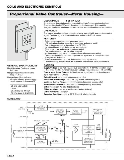
COILS AND ELECTRONIC CONTROLS<br />
Proportional Valve Controller—Metal Housing—<br />
GENERAL SPECIFICATIONS<br />
Metal Housing: Conformal coated;<br />
IP67 rated<br />
Weight: Metal Box without cable:<br />
400 g (14.1 oz.)<br />
Connections: Mounted cable<br />
with unterminated wires provided;<br />
Length: Approx. 1.5 meters (59")<br />
UL and cUL Listed:<br />
UL508<br />
CSA C22.2 No. 14-M91<br />
CE: EN 50081-2, EN50082-2<br />
DESCRIPTION 4–20 mA Input<br />
A metal box-style control amplifier for controlling HydraForce proportional valves.<br />
The metal housing is IP67 rated. Remote mounting is required. This model is<br />
designed for circuits with long wire runs or where electrical interference is a problem.<br />
OPERATION<br />
This control module supplies a proportional valve solenoid with a proportional control<br />
signal. The input signal to this controller can be from a 4–20 mA source.<br />
FEATURES<br />
• Adjustments accessible under removable cover.<br />
• LED indication of output power level, input level and power on/off.<br />
• One unit covers supply voltages from 9 to 32 VDC.<br />
• No internal fuses; circuit limits current electronically.<br />
• Short circuit proof and reverse polarity protected.<br />
• Can be disconnected from coil when powered.<br />
• Maximum current adjustment does not affect minimum current setting.<br />
• Current sensing circuit maintains output current regardless of changes in output<br />
voltage or coil resistance.<br />
• Filter eliminates electrical noise; Independent ramp adjustments.<br />
• Di<strong>the</strong>r frequency and amplitude are adjustable for maximum valve performance.<br />
RATINGS<br />
Supply Voltage: 9–32 VDC (UL and cUL approval is for 9–28 VDC operation only)<br />
Coil rating must be matched with supply voltage: RCOIL ≤ (VSUPPLY – 1.5 V) / I-Max.<br />
Control Input Signal Options: 4–20 mA current signal (see connection diagram)<br />
Input Resistance: 33K Ohms<br />
Output Current: up to 2000 mA (see ordering info.)<br />
Minimum Current Range: 0–500 mA (adjustable; see ordering info.)<br />
Maximum Current Range: 600–2000 mA (adjustable; see ordering info.)<br />
Ramp Up and/or Down: 0.01–5.0 seconds (independently adjustable)<br />
Di<strong>the</strong>r Frequency: 70–350 Hz (adjustable)<br />
Di<strong>the</strong>r Amplitude: 0–10% of maximum current (adjustable)<br />
Di<strong>the</strong>r Waveform: Triangular<br />
Operating Conditions: –20° to 85°C; 0 to 85% relative humidity<br />
SCHEMATIC<br />
V PS +<br />
(9-32 VDC)<br />
–<br />
NOT USED<br />
POWER<br />
GND<br />
ACTIVE<br />
REVERSE POLARITY<br />
PROTECTION<br />
STEP-DOWN<br />
CONVERTER<br />
V PS TO 5.5 V<br />
+5 V<br />
STEP-UP<br />
DC/DC<br />
CONVERTER<br />
+12 V<br />
–12 V<br />
INPUT, OUTPUT<br />
AND<br />
POWER SUPPLY<br />
INDICATORS<br />
RAMP UP<br />
RAMP DOWN<br />
+5 V<br />
CURRENT LOOP TRANSMITTER<br />
NOT USED<br />
CURRENT IN<br />
(4-20 mA)<br />
ANALOG GND<br />
INDEPENDENT<br />
RAMP CONTROL<br />
FUNCTION<br />
DITHER FREQUENCY<br />
R D<br />
R DITHER<br />
DITHER<br />
GENERATOR<br />
I-MAX.<br />
R MAX.<br />
DITHER<br />
AMPLITUDE<br />
I-MIN.<br />
R M<br />
R MIN.<br />
R DA<br />
ERROR<br />
AMPLIFIER<br />
+<br />
–<br />
VOLTAGE<br />
TO<br />
HIGH FREQUENCY<br />
PWM<br />
CONVERTER<br />
CURRENT<br />
SENSING AND<br />
SHORT CIRCUIT<br />
PROTECTION<br />
LOW<br />
PASS<br />
FILTER<br />
C F<br />
S 1<br />
SOLENOID<br />
OUTPUT<br />
S 2<br />
ENABLE<br />
3.532.1