Navigate the Catalog HYDRAFORCE
Navigate the Catalog HYDRAFORCE
Navigate the Catalog HYDRAFORCE
- No tags were found...

You also want an ePaper? Increase the reach of your titles
YUMPU automatically turns print PDFs into web optimized ePapers that Google loves.
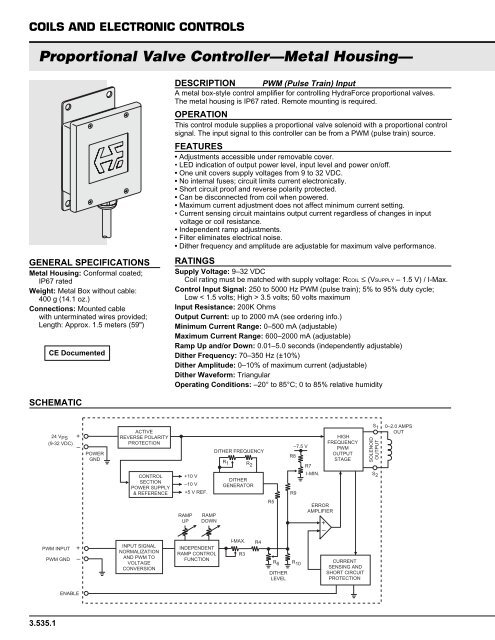
COILS AND ELECTRONIC CONTROLS<br />
Proportional Valve Controller—Metal Housing—<br />
GENERAL SPECIFICATIONS<br />
Metal Housing: Conformal coated;<br />
IP67 rated<br />
Weight: Metal Box without cable:<br />
400 g (14.1 oz.)<br />
Connections: Mounted cable<br />
with unterminated wires provided;<br />
Length: Approx. 1.5 meters (59")<br />
CE Documented<br />
DESCRIPTION PWM (Pulse Train) Input<br />
A metal box-style control amplifier for controlling HydraForce proportional valves.<br />
The metal housing is IP67 rated. Remote mounting is required.<br />
OPERATION<br />
This control module supplies a proportional valve solenoid with a proportional control<br />
signal. The input signal to this controller can be from a PWM (pulse train) source.<br />
FEATURES<br />
• Adjustments accessible under removable cover.<br />
• LED indication of output power level, input level and power on/off.<br />
• One unit covers supply voltages from 9 to 32 VDC.<br />
• No internal fuses; circuit limits current electronically.<br />
• Short circuit proof and reverse polarity protected.<br />
• Can be disconnected from coil when powered.<br />
• Maximum current adjustment does not affect minimum current setting.<br />
• Current sensing circuit maintains output current regardless of changes in input<br />
voltage or coil resistance.<br />
• Independent ramp adjustments.<br />
• Filter eliminates electrical noise.<br />
• Di<strong>the</strong>r frequency and amplitude are adjustable for maximum valve performance.<br />
RATINGS<br />
Supply Voltage: 9–32 VDC<br />
Coil rating must be matched with supply voltage: RCOIL ≤ (VSUPPLY – 1.5 V) / I-Max.<br />
Control Input Signal: 250 to 5000 Hz PWM (pulse train); 5% to 95% duty cycle;<br />
Low < 1.5 volts; High > 3.5 volts; 50 volts maximum<br />
Input Resistance: 200K Ohms<br />
Output Current: up to 2000 mA (see ordering info.)<br />
Minimum Current Range: 0–500 mA (adjustable)<br />
Maximum Current Range: 600–2000 mA (adjustable)<br />
Ramp Up and/or Down: 0.01–5.0 seconds (independently adjustable)<br />
Di<strong>the</strong>r Frequency: 70–350 Hz (±10%)<br />
Di<strong>the</strong>r Amplitude: 0–10% of maximum current (adjustable)<br />
Di<strong>the</strong>r Waveform: Triangular<br />
Operating Conditions: –20° to 85°C; 0 to 85% relative humidity<br />
SCHEMATIC<br />
+<br />
24 V PS<br />
(9-32 VDC)<br />
–<br />
POWER<br />
GND<br />
ACTIVE<br />
REVERSE POLARITY<br />
PROTECTION<br />
CONTROL<br />
SECTION<br />
POWER SUPPLY<br />
& REFERENCE<br />
+10 V<br />
–10 V<br />
+5 V REF.<br />
DITHER FREQUENCY<br />
R 1 R 2<br />
DITHER<br />
GENERATOR<br />
R8<br />
R9<br />
–7.5 V<br />
R7<br />
I-MIN.<br />
HIGH<br />
FREQUENCY<br />
PWM<br />
OUTPUT<br />
STAGE<br />
S 1<br />
SOLENOID<br />
OUTPUT<br />
S 2<br />
0–2.0 AMPS<br />
OUT<br />
RAMP<br />
UP<br />
RAMP<br />
DOWN<br />
R5<br />
ERROR<br />
AMPLIFIER<br />
+<br />
–<br />
PWM INPUT<br />
PWM GND<br />
+<br />
–<br />
INPUT SIGNAL<br />
NORMALIZATION<br />
AND PWM TO<br />
VOLTAGE<br />
CONVERSION<br />
INDEPENDENT<br />
RAMP CONTROL<br />
FUNCTION<br />
I-MAX.<br />
R3<br />
R4<br />
R 6 R 10<br />
DITHER<br />
LEVEL<br />
CURRENT<br />
SENSING AND<br />
SHORT CIRCUIT<br />
PROTECTION<br />
ENABLE<br />
3.535.1