Navigate the Catalog HYDRAFORCE
Navigate the Catalog HYDRAFORCE
Navigate the Catalog HYDRAFORCE
- No tags were found...

Create successful ePaper yourself
Turn your PDF publications into a flip-book with our unique Google optimized e-Paper software.
COILS AND ELECTRONIC CONTROLS<br />
Electronics in <strong>the</strong> Mobile Equipment Industries<br />
ELECTRONIC CONTROL OF HYDRAULIC SYSTEMS (cont’d)<br />
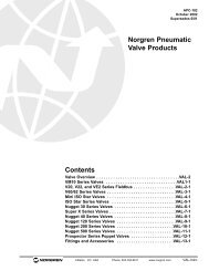
The advantage of using high frequency PWM is that di<strong>the</strong>r can<br />
be generated separately and <strong>the</strong>n superimposed on top of <strong>the</strong><br />
output current (see Fig. 6). This allows <strong>the</strong> user to independently<br />
control <strong>the</strong> current level, as well as <strong>the</strong> di<strong>the</strong>r frequency<br />
and amplitude. The di<strong>the</strong>r will <strong>the</strong>refore be constant for any<br />
current level, and its frequency and amplitude can be set by<br />
<strong>the</strong> user to optimize <strong>the</strong> function of <strong>the</strong> particular hydraulic<br />
valve.<br />
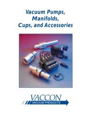
Independent ramps (see Fig. 8) have separate potentiometers<br />
for <strong>the</strong> increasing and decreasing sides, allowing acceleration<br />
and deceleration to be set independently of one ano<strong>the</strong>r.<br />
+<br />
Input<br />
Signal<br />
Independent Ramps<br />
Ramp<br />
Ramp<br />
Frequency<br />
70–350 Hz<br />
0<br />
Time<br />
Fig. 8<br />
Amplitude<br />
10% of<br />
2 Amps Max.<br />
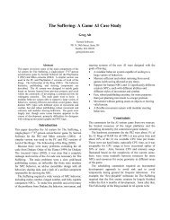
Dual-coil bi-directional valve drivers offer two independent<br />
ramps per coil, for a total of four independently controlled<br />
ramps (see Fig. 9).<br />
Ramps<br />
Superimposed Di<strong>the</strong>r<br />
Fig. 6<br />
Ramps are used to slow down <strong>the</strong> response of <strong>the</strong> valve driver<br />
to a changing command input. This results in a smooth<br />
transition when an abrupt change of <strong>the</strong> command input signal<br />
occurs. Ramps have no effect if <strong>the</strong> input signal change is<br />
slower than <strong>the</strong> ramp setting.<br />
Ramps can be fixed or adjustable, symmetrical or independent,<br />
and single or dual. Adjustable ramps usually operate in <strong>the</strong><br />
zero to eight second range and are controlled by a potentiometer.<br />
Single-side ramps are usually used in slow-shift controls<br />
where only acceleration is a concern.<br />
Symmetrical ramps (see Fig. 7) are controlled by a single<br />
potentiometer that adjusts <strong>the</strong> increasing and decreasing<br />
ramps identically.<br />
Dual Solenoid Driver with Independent Ramps<br />
+<br />
Input<br />
Signal<br />
0<br />
Input<br />
Signal<br />
–<br />
Ramp<br />
Ramp<br />
Time<br />
Fig. 9<br />
Gain or I-Max.<br />
The gain of an amplifier is <strong>the</strong> ratio of its large output signal (to<br />
<strong>the</strong> valve) to its small control input signal.<br />
Gain = Output Signal ÷ Input Signal<br />
The gain is usually adjusted by a potentiometer on <strong>the</strong> amplifier.<br />
This adjustment is usually called “I-Max.” Adjusting <strong>the</strong><br />
I-Max. adjusts <strong>the</strong> amplifier gain. This can be used to adjust<br />
<strong>the</strong> maximum output of <strong>the</strong> amplifier (which controls <strong>the</strong> valve<br />
setting) for full input signal.<br />
Ramp<br />
Ramp<br />
+<br />
Input<br />
Signal<br />
0<br />
Symmetrical Ramps<br />
Ramp<br />
Time<br />
Fig. 7<br />
Ramp<br />
Enable/Disable<br />
Some control/amplifiers incorporate an “Enable” function. This<br />
is a safety feature that requires a specific voltage to be present<br />
at <strong>the</strong> enable connection before <strong>the</strong> output of <strong>the</strong> controller will<br />
operate. Enable can be used for an emergency stop switch or<br />
o<strong>the</strong>r safety interlock device.<br />
While it is possible to place an emergency stop switch in <strong>the</strong><br />
power supply, this is not recommended because stored<br />
charges in capacitors can maintain <strong>the</strong> valve signal for a period<br />
of time after <strong>the</strong> switch is opened.<br />
3.561.3