CIMPS-abs.pdf
CIMPS-abs.pdf
CIMPS-abs.pdf
- No tags were found...

Create successful ePaper yourself
Turn your PDF publications into a flip-book with our unique Google optimized e-Paper software.
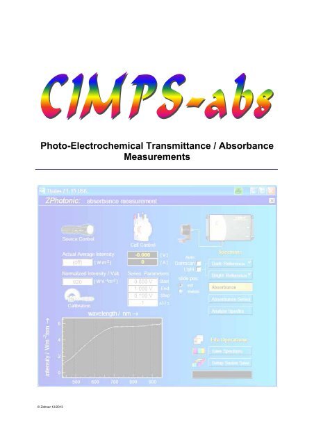
Photo-Electrochemical Transmittance / Absorbance<br />
Measurements<br />
© Zahner 12/2013
<strong>CIMPS</strong>-<strong>abs</strong> -2-
<strong>CIMPS</strong>-<strong>abs</strong> -3-<br />
1. Introduction _______________________________ 5<br />
2. Hardware and Installation____________________ 6<br />
2.1. System components ....................................................................6<br />
2.1.1. Wideband high power LED ..................................................................... 6<br />
2.1.2. Tungsten halogen light source .............................................................. 7<br />
2.1.3. Deuterium tungsten light source ........................................................... 8<br />
2.2. <strong>CIMPS</strong> actuator.............................................................................9<br />
2.2.1. Driver Installation .................................................................................... 9<br />
2.2.2. NET VI..................................................................................................... 10<br />
2.3. UV/VIS spectrometer..................................................................11<br />
2.3.1. ILT-9x0 Installation, SpectrILight Version 3.2.x and higher............... 11<br />
2.3.2. ILT-9x0 Installation, SpectrILight Version 3.1.x and lower ................ 14<br />
2.3.3. AVASPEC ............................................................................................... 16<br />
2.3.4. ILT Control ............................................................................................. 17<br />
3. Software _________________________________ 19<br />
3.1. Startup.........................................................................................19<br />
3.2. Light Source Calibration............................................................20<br />
3.3. Cell Control.................................................................................21<br />
3.4. Spectrometer Settings ...............................................................22<br />
3.5. Dark Reference Spectra.............................................................22<br />
3.6. Bright Reference Spectra ..........................................................22<br />
3.7. Single Absorbance Measurements...........................................23<br />
3.8. Saving single spectra ................................................................24<br />
3.9. Absorbance Series Parameters ................................................24<br />
3.10. Setup Series Save ....................................................................25<br />
3.11. Starting <strong>abs</strong>orbance series .....................................................26
<strong>CIMPS</strong>-<strong>abs</strong> -4-<br />
4. Trouble shooting __________________________ 27<br />
4.1. <strong>CIMPS</strong> Actuator ..........................................................................27<br />
4.2. ILT 9x0.........................................................................................28
<strong>CIMPS</strong>-<strong>abs</strong> -5-<br />
1. Introduction<br />
<strong>CIMPS</strong>-<strong>abs</strong> was designed to integrate light <strong>abs</strong>orption spectroscopy and general spectroelectrochemical<br />
measurements into the service of the Thales-Zennium system environment. A<br />
wideband spectrometer together with an appropriate light source extends <strong>CIMPS</strong> for that purpose.<br />
High precision spectroscopy is enabled by means of a electro-mechanical slide, which supports the<br />
automatic change between the measurement cell and a reference cell in the optical path between light<br />
source and spectrometer head. <strong>CIMPS</strong>-<strong>abs</strong> is established as standard with a spectrometer allowing<br />
wideband spectroscopy between 250nm and 950nm with 1nm resolution. On request, different<br />
spectrometer configurations are available.<br />
Both a high-power LED as well as a tungsten lamp can be ordered as standard. The high-power LED<br />
has the advantage of low power consumption and arbitrarily variable intensity and it can be used in<br />
normal <strong>CIMPS</strong> applications as well. The tungsten light source in turn has a significantly wider spectral<br />
range and higher <strong>abs</strong>olute power. The unique <strong>CIMPS</strong> feedback principle, active also in the case of the<br />
tungsten light source, provides fast settling time and high long-term stability. Thus, the tungsten light<br />
source can be activated and deactivated automatically in long term measurement campaigns, saving<br />
energy and avoiding unwanted heat up. Besides of manually triggered spectra, automatic series of<br />
<strong>abs</strong>orption spectra in dependency of electrochemical parameters can be run in single sweep, cyclic, or<br />
vs. time.<br />
Core applications of <strong>CIMPS</strong>-<strong>abs</strong> are investigations on electro-chromic processes and the<br />
characterization of polymers suitable for organic solar cells and light emitting devices. The <strong>CIMPS</strong>-<strong>abs</strong><br />
set-up includes the spectral resolved emission spectroscopy service <strong>CIMPS</strong>-emit. Please refer to the<br />
<strong>CIMPS</strong>-emit manual for further information on this feature.<br />
<strong>CIMPS</strong>-<strong>abs</strong> comes up as a plug & play application fully calibrated and established with the exemplary<br />
comfort of Thales: spectral data can be analyzed with the on-board package “light spectra analysis”,<br />
spectral data files are covered by the preview-support of the Windows® file explorer and can be<br />
exported in manifold way as high-quality vector graphic, bitmap and ASCII data list. Online-viewing<br />
and export is possible, while measurements are still running and context-sensitive online help is<br />
supported.<br />
|impedance| / Ω<br />
0.6<br />
-100 mV<br />
100K<br />
0.5<br />
+575 mV<br />
30K<br />
extinction →<br />
0.4<br />
0.3<br />
+675 mV<br />
+750 mV<br />
10K<br />
3K<br />
1K<br />
+350 mV<br />
0 mV<br />
0.2<br />
300<br />
0.1<br />
100<br />
+750 mV<br />
0<br />
400 500 600 700 800 900<br />
wavelength / nm →<br />
30<br />
100m 1 3 10 30 100 1K 3K 10K<br />
frequency / Hz →<br />
Fig. 1 A typical application example for <strong>CIMPS</strong>-<strong>abs</strong>: Extinction spectra series vs. cell voltage referenced to<br />
Ag/AgCl 3m-NaCl of a P3HT-PEDOT:PSS film in Acetonitrile / TBA-PF 6 (left hand side) and the corresponding<br />
impedance spectra (right hand side).
<strong>CIMPS</strong>-<strong>abs</strong> -6-<br />
2. Hardware and Installation<br />
The following hardware is required for <strong>CIMPS</strong>-<strong>abs</strong>:<br />
2.1. System components<br />
• Wideband LED, tungsten halogen light source or deuterium tungsten light source<br />
• PECC-2 with transparent reverse side<br />
• Actuator for automatic exchange of reference and measurement cell<br />
• UV/VIS or IR-spectrometer, e.g. International Light ILT-900, ILT-950 or Avantes AVASPEC<br />
2.1.1. Wideband high power LED<br />
The light source, actuator with the slider carrying the cells (PECC) and the input optics of the UV/VISspectrometer<br />
are mounted on the optical bench according to Fig. 2. The <strong>abs</strong>olute intensity calibration<br />
is valid for a distance of 100 mm between the front plate of the LED and the PECC window. The<br />
<strong>CIMPS</strong> aligner bar can be used to adjust this distance.<br />
Fig. 2 Components of <strong>CIMPS</strong>-<strong>abs</strong> with high power LED mounted on the optical bench<br />
The probe E/I connectors of the light source are connected to the slave potentiostat PP211/XPot using<br />
the cable supplied with <strong>CIMPS</strong>-<strong>abs</strong>. The photo sensor located in front of the cells is connected to the<br />
BNC socket of the light source. If the photo sensor is disconnected or shaded while the light source is<br />
active, it is deactivated by a protective circuit. The light source can be reactivated by turning it off and<br />
on again in the software.<br />
The position of the photo sensor is adjusted in factory to the dimensions given in Fig. 2 and Fig. 6.<br />
Height (47.5 mm) and position orthogonal to beam direction (41.5 mm) can easily be checked using<br />
the <strong>CIMPS</strong> aligner bar.<br />
Please note that LED and tungsten light sources require different photo sensors. If more than one<br />
sensor is delivered refer to the file c:\thales\cimps\sensors.txt in order to install the correct sensor.<br />
The input optics of the UV/VIS-spectrometer is fixed on the optical bench just behind the PECC.<br />
Adjust this distance in a way, that the actuator can move the cells without touching the input optics.<br />
Avoid too large gaps because scattering light entering the input optics can degrade the spectra<br />
accuracy.<br />
When using LED light sources an enclosure covering the complete optical bench is recommended to<br />
avoid detrimental effects caused by ambient light during the whole measurement time. Due to the high<br />
light intensity of tungsten halogen light sources here a low level of ambient light is acceptable.
<strong>CIMPS</strong>-<strong>abs</strong> -7-<br />
2.1.2. Tungsten halogen light source<br />
The light source, actuator with the slider carrying the cells (PECC) and the input optics of the UV/VISspectrometer<br />
are mounted on the optical bench according to Fig. 3. The <strong>abs</strong>olute intensity calibration<br />
of the tungsten lamp is valid for a distance of 180 mm measured between the supports of tungsten<br />
lamp and slider with cells (PECC). So this distance has to be adjusted to 180 mm when the<br />
components are mounted on the optical bench.<br />
Fig. 3 Components of <strong>CIMPS</strong>-<strong>abs</strong> with tungsten lamp mounted on the optical bench<br />
The probe E/I connectors of the light source are connected to the slave potentiostat PP211 using the<br />
cable supplied with <strong>CIMPS</strong>-<strong>abs</strong>. The photo sensor located in front of the cells is connected to the BNC<br />
socket of the light source. If the photo sensor is disconnected or shaded while the light source is<br />
active, it is deactivated by a protective circuit. The light source can be reactivated by turning it off and<br />
on again in the software.<br />
The position of the photo sensor is adjusted in factory to the dimensions given in Fig. 3 and Fig. 6.<br />
Height (47.5 mm) and position orthogonal to beam direction (41.5 mm) can easily be checked using<br />
the <strong>CIMPS</strong> aligner bar.<br />
Please note that LED and tungsten light sources require different photo sensors. If more than one<br />
sensor is delivered refer to the file c:\thales\cimps\sensors.txt in order to install the correct sensor.<br />
The input optics of the UV/VIS-spectrometer is fixed on the optical bench just behind the PECC.<br />
Adjust this distance in a way, that the actuator can move the cells without touching the input optics.<br />
Avoid too large gaps because scattering light entering the input optics can degrade the spectra<br />
accuracy.
<strong>CIMPS</strong>-<strong>abs</strong> -8-<br />
2.1.3. Deuterium tungsten light source<br />
The light source fibre optics, the actuator with the slider carrying the cells (PECC) and the input optics<br />
of the UV/VIS-spectrometer are mounted on the optical bench according to Fig. 4.<br />
Fig. 4 Components of <strong>CIMPS</strong>-<strong>abs</strong>/uvn with light source fibre optic mounted on the optical bench<br />
The probe E/I connectors of the Avantes light source interface are connected to the slave potentiostat<br />
PP211/XPot using the cable supplied with <strong>CIMPS</strong>-<strong>abs</strong>. The deuterium tungsten light source is<br />
connected to the Avantes light source interface box according to Fig. 5.<br />
Fig. 5 <strong>CIMPS</strong>-<strong>abs</strong>/uvn schematic system configuration
<strong>CIMPS</strong>-<strong>abs</strong> -9-<br />
2.2. <strong>CIMPS</strong> actuator<br />
The <strong>CIMPS</strong> actuator switches automatically between a reference cell used for the bright reference and<br />
a measurement cell. The two cells are mounted side by side on the actuator as sketched in Fig. 6. So<br />
the bright standard can be either an empty cell (only the glass windows), a cell filled with solvent or the<br />
whole electrolyte.<br />
For the <strong>CIMPS</strong>-<strong>abs</strong>/uvn setup both fibre optics have to be justified orthogonal to get maximum light<br />
intensity according to Fig. 7.<br />
Fig. 6 <strong>CIMPS</strong> Actuator position of reference and measurement cell<br />
Fig. 7 <strong>CIMPS</strong>-<strong>abs</strong>/uvn fibre optic alignment and cell positions<br />
2.2.1. Driver Installation<br />
The <strong>CIMPS</strong> actuator is controlled by a separate controller box connected to the Thales PC via USB.<br />
When this controller box is connected the first time to the PC the USB drivers have to be installed. In<br />
the first dialog of the hardware installation wizard (see Fig. 8 left hand side) choose the option not to
<strong>CIMPS</strong>-<strong>abs</strong> -10-<br />
connect to Windows Update. In the second dialog activate the option to manually choose the driver<br />
location.<br />
Fig. 8 Installation of <strong>CIMPS</strong> Actuator USB drivers<br />
In the next dialog (see Fig. 9, left hand side) enter the path C:\THALES\usb\FTDI and activate the<br />
option to search this path. Now the driver is installed and another dialog (see Fig. 9, right hand side)<br />
informs about the successful installation. Now Windows detects a USB serial port as second device.<br />
Proceed with the installation exactly the same way as with the first device.<br />
Fig. 9 Installation of <strong>CIMPS</strong> Actuator drivers - part 2<br />
2.2.2. NET VI<br />
The actuator is integrated into Thales by a NET VI application called <strong>CIMPS</strong> Actuator. The concept of<br />
NET VIs is described in the separate manual Signal Acquisition and NET VI. As the NET VI is<br />
controlled completely by Thales, the application window only displays the actual status (Fig. 10). The<br />
NET VI application is started automatically during startup of <strong>CIMPS</strong>-<strong>abs</strong> (c.f. chapter 3.1) and should<br />
not be closed during use of <strong>CIMPS</strong>-<strong>abs</strong>.<br />
The TCP/IP-support used for communication between Thales and the <strong>CIMPS</strong> Actuator Net VI is<br />
activated by default for Thales Z1.29 an newer. For older versions it has to be switched on manually<br />
as follows. Open the configuration file of Thales (default: c:\Flink\usb.ini) and locate the entry<br />
DEVICESUP=off. Change it to DEVICESUP=on and save the configuration file.
<strong>CIMPS</strong>-<strong>abs</strong> -11-<br />
Fig. 10 <strong>CIMPS</strong> Actuator application<br />
At each start <strong>CIMPS</strong> Actuator initializes by moving the slider to both end positions. After initialization<br />
the slider returns to the home position of 0 mm with the reference cell in the light path. During shut<br />
down <strong>CIMPS</strong> Actuator also returns the slider to the home position at 0 mm.<br />
2.3. UV/VIS spectrometer<br />
<strong>CIMPS</strong>-<strong>abs</strong> is delivered with either an International Light ILT-9x0 or an Avantes AVASPEC UV/VISspectrometer.<br />
The ILT-9x0 requires the manual installation of the SpectrILight software package<br />
delivered on the yellow International Light installation disk(s).<br />
Please note the installation procedure depends on the software version of SpectrILight. All <strong>CIMPS</strong>-<strong>abs</strong><br />
systems delivered after 01.03.2011 include SpectrILight version 3.2.x or later. In this case refer to<br />
chapter 2.3.1 for installation.<br />
In case your SpectrILight version is 3.1.x and lower, as with <strong>CIMPS</strong>-<strong>abs</strong> systems delivered before<br />
28.02.2011, refer to chapter 2.3.2 for installation.<br />
The <strong>CIMPS</strong>-<strong>abs</strong>/uvn system is delivered with an Avantes AVASPEC spectrometer. In this case refer to<br />
chapter 2.3.3 for installation.<br />
Warning: Do not connect the spectrometer before the software including the USB drivers of the<br />
spectrometer is installed.<br />
2.3.1. ILT-9x0 Installation, SpectrILight Version 3.2.x and higher<br />
Insert the SpectrILight III installation disk labeled SOFTWARE into your CD-ROM drive, locate the<br />
folder CD-ROM:\Installer\SpectrILight III v3.x.x\Installer\Volume and start setup.exe.<br />
Fig. 11 SpectrILight installation first and last window<br />
Follow the instructions until installation is complete (Fig. 11). Now the ILT-9x0 interface package<br />
installation automatically starts. Again follow the instructions until the drivers are installed (Fig. 12).
<strong>CIMPS</strong>-<strong>abs</strong> -12-<br />
Fig. 12 ILT-950 interface package installation<br />
In a second step the DLL for communication with Thales has to be installed. Locate the directory<br />
CD-ROM:\SDK\SpectrILight III DLL\Installer\Volume and start setup.exe. Installation is very similar to<br />
SpectrILight III.<br />
Fig. 13 SpectrILight DLL installation first and last window<br />
Now plug in the USB-connector of the ILT-9x0. Windows will detect a new USB device and start the<br />
driver installation. Only Windows XP: In the first dialog (Fig. 14, left hand side) choose not to connect<br />
to Windows Update and continue with the automatic installation (Fig. 14, right hand side).<br />
Fig. 14 Windows driver installation for the ILT-9x0 spectrometer<br />
As the driver package was preinstalled before, the driver can be directly installed from c:\windows\inf<br />
(Fig. 15).
<strong>CIMPS</strong>-<strong>abs</strong> -13-<br />
Fig. 15 Windows driver installation for the ILT-9x0 spectrometer continued<br />
Before using the spectrometer, the corresponding wavelength and irradiance calibration file has to be<br />
loaded in the SpectrILight III software. Therefore start the SpectrILight III application using the desktop<br />
icon, see Fig. 16 left hand side. At the first startup of SpectrILight III the folders for user and calibration<br />
data are created. The activation code asked for is printed on the CD cover.<br />
Now insert the SpectrILight III installation disk labeled SOFTWARE CALIBRATION DATA into your<br />
CD-ROM drive and locate the folder CD-ROM:\Cal_File. It contains a spectrometer calibration file<br />
ILTXXXXYYYY.cal where XXXX denotes the serial number of the spectrometer and YYYY the type of<br />
input optics, e.g. ILT1007122U1W2.cal. Copy this file to the following folder:<br />
Windows XP:<br />
Documents and Settings\username\Local Settings\Application Data\International Light\SpectrILight III\<br />
Calibration<br />
Windows Vista, Windows 7:<br />
Users\username\AppData\Local\International Light\SpectrILight III\Calibration<br />
Username is the name of the user currently logged in. In case of doubt about the correct folder check<br />
the preset folder in the calibration file dialog. After the calibration file is copied, click the cogwheelbutton<br />
(see Fig. 16 right hand side) and choose the calibration file in the file dialog.<br />
Fig. 16 Activation of the spectrometer calibration file in SpectrILight<br />
If the calibration file was loaded successfully its name is indicated in the status line of SpectrILight III<br />
as shown in Fig. 17. Otherwise UNCALIBRATED indicates that no calibration file will be used and<br />
measured wavelength and irradiance will differ from the correct values. SpectrILight III memorizes the<br />
setting of the calibration file so it has only to be loaded once.<br />
Before using the ILT9x0 spectrometer with Thales <strong>CIMPS</strong> make sure to close SpectrILight III. The<br />
spectrometer is controlled completely by the Thales Software Package using ILTControl.
<strong>CIMPS</strong>-<strong>abs</strong> -14-<br />
Fig. 17 Status line of SpectrILight indicating the loaded calibration file<br />
2.3.2. ILT-9x0 Installation, SpectrILight Version 3.1.x and lower<br />
The ILT-9x0 spectrometer is supplied with a separate CD-ROM containing both SpectrILight software<br />
and calibration data. Insert the SpectrILight III software installation disk and locate the folder<br />
ILTXXXX\Installer\Volume v.3.Y.Y where XXXX denotes the serial number of the spectrometer and<br />
Y.Y the version number of the software. Start the installation program setup.exe and follow the<br />
instructions. In a second step the DLL for communication with Thales has to be installed. Open the<br />
directory ILTXXXX\SDK\SpectrILight III DLL v3.Y.Y\Installer\Volume v.3.Y.Y\ and start setup.exe<br />
After SpectrILight installation is finished, plug in the spectrometer. Windows will detect a new USB<br />
device and start the driver installation as shown in Fig. 18, left hand side. In the first dialog chose not<br />
to connect to Windows Update. If the SP SM ILX USB2.0 (in case of the ILT-900) or ILT-USB2 (in<br />
case of the ILT-950) is suggested for installation in the second dialog, see Fig. 18, right hand side,<br />
continue with the automatic installation. In case the correct driver is not found automatically, choose<br />
the Drivers folder of the SpectrILight installation (default: C:\Programme\International<br />
Light\SpectrlLight III\Drivers).<br />
Fig. 18 Windows driver installation for the ILT-900 spectrometer<br />
Before using the spectrometer, the corresponding wavelength and irradiance calibration file has to be<br />
loaded in the SpectrILight III software. It is located on the SpectrILight installation CD in the folder<br />
Cal_File with a filename ILTXXXXYYYY.cal where XXXX denotes the serial number of the<br />
spectrometer and YYYY the type of input optics, e.g. ILT3062W2SP.cal. Copy this file to the<br />
calibration folder of the SpectrILight III software which is C:\Programme\International Light\SpectrlLight<br />
III\Calibration in a default installation.<br />
Now start the SpectrILight III software, click the CAL-button (see Fig. 19) and chose this calibration file<br />
in the file dialog.
<strong>CIMPS</strong>-<strong>abs</strong> -15-<br />
Fig. 19 Activation of the spectrometer calibration file in SpectrILight<br />
If the calibration file was loaded successfully its name is indicated in the status line of SpectrILight III<br />
as shown in Fig. 20. Otherwise UNCALIBRATED indicates that no calibration file will be used and<br />
measured wavelength and irradiance will differ from the correct values. SpectrILight III memorizes the<br />
setting of the calibration file so it has only to be loaded once.<br />
Fig. 20 Status line of SpectrILight indicating the loaded calibration file<br />
Finally the Dynamic Link Library (DLL) for communication between Thales and the spectrometer has<br />
to be installed. The procedure depends on the software version of SpectrIlight III.<br />
For version 3.1.15 and newer:<br />
Start the DLL-installer on the SpectrIlight installation CD located in ILTXXXX\SDK\SpectrILight III DLL<br />
v3.Y.YY\Installer\Volume v.3.Y.YY\setup.exe where XXXX denotes type and serial number of the<br />
spectrometer and Y.YY the version number of the software. Install the DLL to the same directory as<br />
the SpectrIlight software.<br />
For versions older than 3.1.15:<br />
Copy SpectrILight.dll from C:\FLINK\ILTControl to the program folder of SpectILight III which is<br />
C:\Programme\International Light\SpectrlLight III in a default installation.<br />
Before using the ILT9x0 spectrometer with Thales <strong>CIMPS</strong> make sure to close SpectrILight III. The<br />
spectrometer is controlled completely by the Thales Software Package using ILTControl.
<strong>CIMPS</strong>-<strong>abs</strong> -16-<br />
2.3.3. AVASPEC<br />
Insert the Avantes installation disk into your CD-ROM drive, the installer will start automatically in your<br />
internet browser (Fig. 21). Otherwise open start.html from your CD-ROM drive using your internet<br />
browser. From the installer menu select Software -> Avasoft 8.0.1 for USB2 to start the software<br />
installation process. Continue with the installation of the software and the spectrometer driver.<br />
Fig. 21 Avantes AVASPEC Software Installation<br />
After the software installation is finished, plug in the spectrometer. Windows will detect a new USB<br />
device and start the driver installation as shown in Fig. 22, left hand side. In the first dialog chose not<br />
to connect to Windows Update. If the AvaSpec-USB2 is suggested for installation in the second<br />
dialog, see Fig. 22, right hand side, continue with the automatic installation.
<strong>CIMPS</strong>-<strong>abs</strong> -17-<br />
Fig. 22 Windows driver installation for the Avantes AVASPEC spectrometer<br />
For further information refer to Avantes AVASPEC operating manual.<br />
2.3.4. ILT Control<br />
The UV/VIS spectrometer is integrated into <strong>CIMPS</strong>-<strong>abs</strong> by an application called ILT Control. It is called<br />
automatically during startup of <strong>CIMPS</strong>-<strong>abs</strong> (c.f. chapter 3.1) and communicates with Thales using a file<br />
interface. The software settings are configured in ILTControl.INI, which is located in<br />
C:\Flink\ILTControl:<br />
[Spectrometer] section<br />
[Paths] section<br />
set the type of the spectrometer<br />
ILTDLLFile and ILTINIFile are only relevant for ILT 9x0 spectrometers!<br />
ILT Control uses a dynamic link library (SpectrILight.dll) of the<br />
SpectrILight software to communicate with the ILT spectrometers. The<br />
paths and filenames of the SpectrILight DLL are defined here<br />
Example of a ILTControl.INI<br />
[Spectrometer]<br />
; Set type of used spectrometer here<br />
; ILT-900, ILT-950 0<br />
; Avantes 1<br />
Spectrometertype=0<br />
[Paths]<br />
; DLL-Path for Windows 7<br />
ILTDLLFile=C:\Program Files (X86)\International Light\SpectrlLight III\SpectrILight.dll<br />
; DLL-Path for Windows XP<br />
; ILTDLLFile=C:\Programme\International Light\SpectrlLight III\SpectrILight.dll<br />
ILTINIFile=C:\Programme\International Light\SpectrlLight III\Para.ini<br />
ILTDLLFile sets the path of the DLL for spectrometer control which is in the SpectrILight installation<br />
folder. If SpectrILight was installed to a different directory change the path accordingly. For Windows<br />
XP comment the blue ILTDLLFile entry for Windows 7 with ; and uncomment the red ILTDLLFile<br />
entry for Windows XP. The example above shows the configuration for Windows 7 with standard<br />
installation path.<br />
Do not change the paths of ControlFile and DataFile which are used for communication with Thales.
<strong>CIMPS</strong>-<strong>abs</strong> -18-<br />
Fig. 23 Window of spectrometer control application ILT Control<br />
It is not necessary to open SpectrILight III / Avasoft in order to use the ILT-9x0/AVASPEC with Thales.<br />
But the spectrometers can also be used without Thales as a stand alone spectrometer with the<br />
SpectrILight III / Avasoft software. For further information please refer to the spectrometer manuals.<br />
Even without directly using SpectrILight III / Avasoft it is necessary for spectrometer communication of<br />
ILT Control, so installation is mandatory.
<strong>CIMPS</strong>-<strong>abs</strong> -19-<br />
3. Software<br />
3.1. Startup<br />
<strong>CIMPS</strong>-<strong>abs</strong> is easily activated by using the pull down menu as shown in Fig. 24. To open the pull<br />
down menu click onto the Z-icon in the title bar of the Thales window.<br />
Fig. 24 Start of <strong>CIMPS</strong>-<strong>abs</strong> using the pull down menu<br />
During startup <strong>CIMPS</strong>-<strong>abs</strong> automatically starts the necessary applications ILT Control and <strong>CIMPS</strong><br />
Actuator. After initialization of the spectrometer and the actuator the main window of <strong>CIMPS</strong>-<strong>abs</strong> is<br />
displayed (see Fig. 25).
<strong>CIMPS</strong>-<strong>abs</strong> -20-<br />
Fig. 25 Main window of <strong>CIMPS</strong>-<strong>abs</strong> after startup<br />
It is similar to the regular <strong>CIMPS</strong> main window regarding source and cell control so chapters 3.1.2 and<br />
4.1 also apply here with some differences specific to <strong>CIMPS</strong>-<strong>abs</strong>.<br />
3.2. Light Source Calibration<br />
Light sources delivered by Zahner come with a calibration file which has to be loaded before using the<br />
light source. In <strong>CIMPS</strong>-<strong>abs</strong> calibration options are limited to opening the calibration file of a light<br />
source. All other tasks related to calibration of light sources can be done in <strong>CIMPS</strong> environment.<br />
Fig. 26 Active icon for loading light source calibration data.<br />
Click the calibration-icon (Fig. 26) and choose the file corresponding to the light source used in the file<br />
dialog (Fig. 27). The name of the calibration file consists of the serial number and the ordering code of<br />
the light source, e.g. 0349wow01 for the tungsten halogen wideband light source with serial number<br />
349.<br />
Fig. 27 File dialog for choosing the calibration file of the light source.
<strong>CIMPS</strong>-<strong>abs</strong> -21-<br />
Each calibration file is valid for a distinct combination of a light source and a sensor. In case several<br />
sensors are delivered they are labelled with consecutive numbers, e.g. S01, S02, S03. Here the<br />
number of the sensor is appended to the file name of the corresponding calibration file. For example<br />
the calibration file for the WLL01 with serial number 28 in combination with sensor S02 is named<br />
0028wll01-s02.is_. Ensure to open the correct calibration file for your set-up. When in doubt which<br />
sensor is used for a specific set-up refer to the file c:\thales\cimps\sensors.txt.<br />
After loading the calibration file of a tungsten halogen light source an automatic check of the<br />
calibration is performed. Ensure the distance between tungsten lamp and cell slider is adjusted to<br />
180 mm as described in chapter 2.1 and the photo sensor is connected. Reload the calibration file<br />
after each change of the tungsten lamp setup in order rerun this check.<br />
Please note: Although the actual average intensity can be set to all values between 0 and maximum<br />
intensity this is not recommended with tungsten halogen light sources. In contrast to LEDs the spectral<br />
distribution of tungsten lamps changes drastically at reduced intensity. When loading a calibration file<br />
the nominal intensity of the tungsten lamp is preset so no manual input is necessary.<br />
3.3. Cell Control<br />
Cell control is located in the middle of the main screen. As in standard <strong>CIMPS</strong> the cell control icon is<br />
used to enter the control menu of the cell potentiostat (main potentiostat of the Zennium) as shown in<br />
Fig. 28. Here the cell state can be set up manually. This is necessary for single <strong>abs</strong>orbance<br />
measurements and series measurements over time. During series measurements over voltage or<br />
current the potentiostat is set automatically so no manual set up is required in this case.<br />
Fig. 28 Active cell control icon and control potentiostat window<br />
The two meters below the cell control icon indicate the actual potential and current of the cell. The<br />
controlled quantity is marked with asterisk, so potentiostatic mode (voltage controlled) and<br />
galvanostatic mode (current controlled) can be distinguished in the <strong>CIMPS</strong>-<strong>abs</strong> main window.
<strong>CIMPS</strong>-<strong>abs</strong> -22-<br />
3.4. Spectrometer Settings<br />
Acquisition of light spectra is done with the controls on the right hand side of the <strong>CIMPS</strong>-<strong>abs</strong> main<br />
window. A click on the spectrometer icon opens the spectrometer settings of Fig. 29, which are valid<br />
for all following measurements.<br />
Fig. 29 Setup of the spectrometer<br />
The wavelength range can be set arbitrarily within the maximum range of the used spectrometer,<br />
which is 250 – 1000 nm for the ILT-9x0. As the ILT-9x0 is a CCD-array spectrometer the entered<br />
wavelength range has no influence on sensitivity, needed acquisition time or other parameters.<br />
Integration time determines the amount of light collected during a single spectrum and can be set<br />
between 1 ms and about 10 s. To reduce noise several spectra can be recorded and averaged<br />
automatically. Please mind the overall measurement time of integration time multiplied with the<br />
number of averages.<br />
3.5. Dark Reference Spectra<br />
Before the spectrometer can record spectra a dark scan has to be done. Therefore the buttons for<br />
bright reference, <strong>abs</strong>orbance and <strong>abs</strong>orbance series are disabled in <strong>abs</strong>ence of a dark scan. During<br />
the dark scan detector dark current, electronic noise and residual scattering light inside the<br />
spectrometer are measured and subtracted automatically from all following spectra. Each change of<br />
the integration time requires a new dark scan.<br />
When using LED light sources please ensure that ambient light is excluded during the dark scan. A<br />
enclosure covering the complete optical bench is recommended to avoid detrimental effects caused by<br />
ambient light during the whole measurement time. Due to the high light intensity of tungsten halogen<br />
light sources here a low level of ambient light is acceptable.<br />
Dark scans can be done manually using the Dark Reference button (Fig. 30). Presence of a valid dark<br />
scan is indicated by a checkmark on the right hand side of the Dark Reference button.<br />
Fig. 30 Manual acquisition of a dark reference spectrum<br />
During series measurements dark reference spectra can be recorded automatically before each<br />
<strong>abs</strong>orbance spectrum by setting the Auto Darkscan option. This is recommended as it eliminates the<br />
drift of the spectrometer dark signal.<br />
3.6. Bright Reference Spectra<br />
The bright reference can either be recorded from the reference cell or the measurement cell. With the<br />
Auto Light option activated (see Fig. 31) the <strong>CIMPS</strong> Actuator is automatically moved to the reference<br />
cell for bright reference spectra and back to the measurement cell for <strong>abs</strong>orbance spectra. Additionally<br />
the default state of the light source can be set. The light source is in the default state whenever no<br />
spectrum is recorded. Because of the high thermal burden of tungsten halogen lamps in this case the<br />
default state is locked to off.
<strong>CIMPS</strong>-<strong>abs</strong> -23-<br />
Fig. 31 Active Auto Light option: automatic change between measurement and reference cell.<br />
With the Auto Light option deactivated no automatic bright reference spectra are recorded. They have<br />
to be acquired by clicking the Bright Reference button. The cell for the bright reference can be chosen<br />
manually with the slide pos option (Fig. 32) before recording the bright reference.<br />
Fig. 32 Auto light option disabled: cell for reference measurement is chosen manually<br />
3.7. Single Absorbance Measurements<br />
With a valid dark and bright reference single <strong>abs</strong>orbance spectra can be recorded using the<br />
Absorbance button (Fig. 33). Before the <strong>abs</strong>orbance spectrum is recorded the slider moves the<br />
measurement cell into the light path. So there is no need to set the slide pos option manually. The<br />
spectrum is acquired at the actual cell state so this has to be preset using the Cell Control (cf. chapter<br />
Cell Control) before. The spectrum is displayed in the lower left side of the window after measurement<br />
and remains in memory until a new spectrum is recorded.<br />
Fig. 33 Start of a Absorbance measurement
<strong>CIMPS</strong>-<strong>abs</strong> -24-<br />
3.8. Saving single spectra<br />
Single <strong>abs</strong>orbance spectra and bright reference spectra can be saved using the Save Spectrum<br />
button (Fig. 34).<br />
Fig. 34 Saving single spectra<br />
The button Save Spectrum opens a description box where additional information about the<br />
measurement can be entered (Fig. 35). Some of the fields are already preset with parameters, others<br />
are available for user comments. After confirming the description box with the checkmark in the upper<br />
right edge a standard file dialog is opened (Fig. 35). Choose path and filename here and confirm with<br />
Save to write the data file.<br />
Fig. 35 Description box and file dialog for saving single <strong>abs</strong>orbance spectra<br />
3.9. Absorbance Series Parameters<br />
Before a series measurement is started the parameters of the series have to be set up by a click on<br />
the meters of the series parameters (see Fig. 36, left hand side). A dialog box now offers voltage,<br />
current or time as changing quantity for the measurements. After choosing one quantity the scan<br />
range is defined in another dialog box.<br />
Fig. 36 Configuration of a series measurement over potential<br />
In case of a series over potential the parameters are entered in the dialog box of Fig. 36. The potential<br />
is varied between the starting value and the ending value in the given step width. If the ending value<br />
cannot be reached with the step width entered, it is adjusted to a larger value so the ending value is<br />
reached exactly. Settling time is the time span between applying a new potential and starting<br />
acquisition of the light spectrum. During this time the electrochemical system investigated can<br />
equilibrate to the new potential. The number of full cycles defines how often the potential is varied<br />
from the starting value to the ending value and back to the starting value, again. A half cycle, as preset<br />
with 0.5 cycles, stops at the ending value. The steps back to the starting value are omitted.
Setting up a series over current is done in an analog way.<br />
<strong>CIMPS</strong>-<strong>abs</strong> -25-<br />
Fig. 37 Configuration of a series measurement over time<br />
In case of a series over time the ending value determines the overall time of the series. Spectra are<br />
recorded every time the step width is reached. If the ending value cannot be reached with the entered<br />
step width, the latter is increased so an integer number of steps matches the ending value. Mind to set<br />
the step time long enough for the light spectrum to be recorded. Otherwise the given step width cannot<br />
be achieved and the spectra are recorded as fast as possible.<br />
3.10. Setup Series Save<br />
In contrast to single <strong>abs</strong>orbance measurements, series measurements are saved automatically so a<br />
series can run unattended. For this reason a filename has to be preset before starting the series with<br />
the Setup Series Save button (Fig. 38). The current filename is displayed below the button.<br />
Fig. 38 Button for entering series filenames and display of actual filename<br />
After clicking the Setup Series Save button a description box is opened where additional information<br />
about the measurement can be entered (Fig. 39, left). In the next step directory and base file name<br />
are chosen (Fig. 39, right). The used filenames consist of this base file name and the running number<br />
of the measurement. With “series” as base filename, the files “series00.isl”, “series01.isl”, … are<br />
written.<br />
Fig. 39 Description box and file dialog for saving <strong>abs</strong>orbance series measurements
<strong>CIMPS</strong>-<strong>abs</strong> -26-<br />
3.11. Starting <strong>abs</strong>orbance series<br />
After series and save parameters are set the <strong>abs</strong>orbance series can be started using the button<br />
Absorbance Series (Fig. 40).<br />
Fig. 40 Starting an <strong>abs</strong>orbance series<br />
In case of a series over potential or current the potential/current is automatically applied to the cell<br />
according to the presets (cf. Fig. 36) and spectra are acquired.<br />
Fig. 41 Reminder to preset file name and description of a series measurement<br />
In case an <strong>abs</strong>orbance series is started without defining the save parameters before, a reminder is<br />
displayed (Fig. 41). After defining the series save parameters the series can be started.
<strong>CIMPS</strong>-<strong>abs</strong> -27-<br />
4. Trouble shooting<br />
4.1. <strong>CIMPS</strong> Actuator<br />
Neterror: Can’t connect local to remote system (127.0.0.1).<br />
<strong>CIMPS</strong> Actuator error: Thales not running.<br />
The TCP/IP-support used for communication between Thales and the <strong>CIMPS</strong> Actuator Net VI is<br />
disabled. Open the configuration file of Thales (default: c:\Flink\usb.ini) and locate the entry<br />
DEVICESUP=off. Change it to DEVICESUP=on and save the configuration file. Close the Thales<br />
window and reopen it in order to activate the new setting.<br />
<strong>CIMPS</strong> Actuator error: Stepper interface not found.<br />
<strong>CIMPS</strong> Actuator error: Stepper Interface is not responding.<br />
Check whether the <strong>CIMPS</strong> actuator controller is connected to an USB port and switched on. Both<br />
LEDs of the actuator controller have to be on. If both LEDs are on but the controller is still not found<br />
switch it off and after ten seconds on again. This can help fixing communication problems.<br />
<strong>CIMPS</strong> Actuator error: End switch not reached. Slider blocked/disconnected<br />
During initialization the slider is moved to both end switches. If they are not reached in the maximal<br />
necessary number of steps this error results. In most of the cases the actuator is simply disconnected<br />
from the controller. If not, check whether the slider is blocked, e.g. by a PECC touching the input<br />
optics of the spectrometer.<br />
<strong>CIMPS</strong> Actuator error message box: Application could not be started because FTD2XX.dll was<br />
not found.<br />
The <strong>CIMPS</strong> Actuator NET VI freezes showing the message “Initializing…” .<br />
An USB-serial-converter has installed and old version of the FTDI USB driver used by the <strong>CIMPS</strong><br />
actuator. The old version of the driver has to be removed and the new version supplied by Zahner<br />
(C:\Flink\<strong>CIMPS</strong>Actuator\drivers) has to be installed. USB-serial-converters remain functional with the<br />
new version. Perform the following steps to remove the old drivers and install the new ones:<br />
1. Unplug all USB-serial-converters and other devices using FTDI USB chips including the Zahner<br />
<strong>CIMPS</strong> Actuator.<br />
2. Call C:\Flink\<strong>CIMPS</strong>Actuator\Uninstaller\CDMUninstallerGUI.exe<br />
3. Check, whether the Vendor ID 0403 and the Product ID 6001 are entered in the input boxes and<br />
click the button Add (see Fig. 42 left hand side). VID and PID are added to the devices pending<br />
uninstallation. Do not enter different Vendor and Product IDs here as this may remove drivers<br />
needed for running Windows properly.<br />
4. With VID_0403 PID_6001 in the large input box click the Remove Devices (see Fig. 42 right hand<br />
side) button. Now the old drivers are uninstalled. After a short moment a dialog box “Device<br />
removed from system” informs about the completed uninstallation.<br />
5. Now the new USB-drivers supplied by Zahner can be installed according to chapter 2.2.1.
<strong>CIMPS</strong>-<strong>abs</strong> -28-<br />
Fig. 42 Uninstallation of FTDI Drivers<br />
4.2. ILT 9x0<br />
ILT Control error message: Error loading International Light DLL. Check path in INI-File and<br />
restart.<br />
ILT Control was not able to open the dynamic link library for spectrometer control. Check whether the<br />
path in C:\Flink\ILTControl\ILTControl.ini is consistent with the installation directory of the SpectrIlight<br />
software (default C:\Program Files\International Light\SpectrlLight III\) and SpectrILight.dll exists in this<br />
directory. If not reinstall the DLL as described in chapter 2.3.2.<br />
ILT Control error message: No SM240 USB devices detected.<br />
ILT Control error message: Error opening spectrometer communication.<br />
The ILT-9x0 spectrometer was not found. Check, whether it is connected to the PC. The ILT-9x0<br />
needs up to 500 mA from the USB port. As bus-powered USB hubs cannot provide this current the<br />
spectrometer will not work with bus-powered hubs. Although self powered hubs may be used,<br />
connecting the ILT-9x0 directly to the PC is recommended.<br />
If the spectrometer is connected but still not detected please unplug and replug it.<br />
After the spectrometer is plugged in Windows finds new hardware and wants to install a driver.<br />
Due to the way Windows handles USB ports the driver has to be installed for each port separately.<br />
The driver files are located in the program directory of SpectrIlight (default C:\Program<br />
Files\International Light\SpectrlLight III\Drivers).<br />
Thales error: No response from spectrometer.<br />
Thales gets no response from ILT Control. Check, if another error has occurred in ILT Control and fix<br />
it. Close ILT Control and confirm the error message. ILT Control should be reopened now<br />
automatically. In case ILT Control was closed accidentally, simply confirm the error message.<br />
SpectrIlight III error message: LabVIEW Development system required<br />
This error message is somewhat misleading as the Microsoft .NET Framework 2.0 is missing. In order<br />
to install the .NET Framework start dotnetfx.exe in the folder ILTXXXX\Tools\DotNetFramework of the<br />
SpectrIlight CD. XXXX denotes the serial number of the ILT-9x0 spectrometer. After installation of the<br />
.NET Framework has finished, install the Service Pack for .NET by starting NetFx20SP1_x86.exe.