OPERATING INSTRUCTIONS - Kiepe Elektrik
OPERATING INSTRUCTIONS - Kiepe Elektrik
OPERATING INSTRUCTIONS - Kiepe Elektrik
- No tags were found...

You also want an ePaper? Increase the reach of your titles
YUMPU automatically turns print PDFs into web optimized ePapers that Google loves.
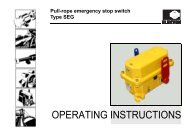
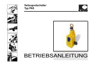
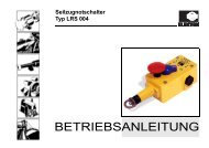
Pull-rope emergency stop switch<br />
Type PRS<br />
<strong>OPERATING</strong> <strong>INSTRUCTIONS</strong>
Legal notice<br />
Operating Instructions (Translation of original)<br />
Document no.: 94.064 131.191<br />
Pull-rope emergency stop switch, Type PRS<br />
Equipment item no.: various<br />
Date of issue: 21.11.2008<br />
Update status: Index 0<br />
CE conformity certificate<br />
The device complies with the relevant European and<br />
national regulations.<br />
CE conformity has been certified; the relevant records<br />
are in the hands of the manufacturer.<br />
Protective note (as per DIN ISO 16016:2002-5)<br />
Forwarding and duplicating this document, as well as<br />
using or revealing its contents are prohibited without<br />
written approval. Noncompliance is subject to<br />
compensatory damages. All rights reserved with regard<br />
to patent claims or submission of design or utility patent.<br />
CONFIDENTIAL<br />
www.kiepe-elektrik.com Vossloh <strong>Kiepe</strong> GmbH Tel.: +49(0)211/7497–0<br />
<strong>Kiepe</strong>-Platz 1<br />
40599 Düsseldorf<br />
Germany<br />
Fax: +49(0)211/7497–420
3<br />
Table of contents<br />
1 For your safety..................................................................................................................5<br />
1.1 Intended use .................................................................................................................................................5<br />
1.2 Design of warnings .......................................................................................................................................6<br />
CONFIDENTIAL<br />
2 Transport, storage and disposal .......................................................................................8<br />
2.1 Transport and packaging ..............................................................................................................................8<br />
2.2 Storage .........................................................................................................................................................8<br />
2.3 Disposal ........................................................................................................................................................8<br />
3 Description........................................................................................................................9<br />
3.1 How the emergency stop function works for all types...................................................................................9<br />
4 Technical data ................................................................................................................11<br />
4.1 General technical data................................................................................................................................11<br />
4.3 Dimensions .................................................................................................................................................13<br />
5 Mounting and dismounting..............................................................................................14<br />
5.1 Scope of delivery ........................................................................................................................................14<br />
5.2 Mounting .....................................................................................................................................................14<br />
5.2.1 Important mounting instructions..................................................................................................................14<br />
5.2.2 KIEPE mounting accessories .....................................................................................................................15<br />
5.2.3 Mechanical mounting..................................................................................................................................16<br />
Operating Instructions<br />
PRS
4<br />
5.2.4 Electrical connection .................................................................................................................................. 21<br />
5.2.4.1 Preparation work........................................................................................................................................ 21<br />
5.2.4.2 Connecting types PRS 001 and PRS 101.................................................................................................. 22<br />
5.3 Dismounting ............................................................................................................................................... 23<br />
6 Maintenance and repair..................................................................................................25<br />
7 Ordering devices, replacement parts and accessories ..................................................26<br />
7.1 Ordering devices........................................................................................................................................ 26<br />
7.2 Ordering replacement parts and accessories ............................................................................................ 27<br />
CONFIDENTIAL<br />
PRS<br />
Operating Instructions
1 For your safety<br />
5<br />
1 For your safety<br />
CONFIDENTIAL<br />
1.1 Intended use<br />
Pull-rope emergency stop switches are used in conveyor<br />
systems for emergency stop of continuous conveyors.<br />
The pull-rope emergency stop switches meet the very<br />
high requirements of industry safety regulations, which<br />
stipulate that emergency stop equipment on conveyor<br />
systems must be used to ensure worker's safety<br />
(VBG 10/BGI 710). The device is intended for use in stationary<br />
installations and in vehicles.<br />
The documentation at hand is to be considered part of<br />
the product and must be retained and be available to the<br />
respective owner/user for the entire service life of the<br />
product. The documentation must be passed on to each<br />
subsequent owner of the product.<br />
The manufacturer is not liable for personal injury and<br />
property damage arising from non-intended use of the<br />
device or unauthorized modifications to the device and<br />
its components. Make sure that the intended use is not<br />
impaired in any way even after unexpected outside<br />
influence on the device.<br />
Intended use refers specifically to the operation of the<br />
device in accordance with these operating instructions.<br />
Work on this device may only be carried out by<br />
qualified personnel who are familiar with accident<br />
prevention regulations as well as other generally<br />
recognized safety regulations.<br />
By using the equipment as intended, you protect<br />
yourself and prevent damage to the equipment and<br />
its components.<br />
Operating Instructions<br />
PRS
6<br />
1 For your safety<br />
1.2 Design of warnings<br />
Risks are classified in accordance with ISO 3864-2 and<br />
ANSI Z535.6 using the keywords<br />
• “Danger,” “Warning,” and “Caution” in the case of<br />
bodily injury,<br />
• “Beware” in the case of property damage, and<br />
• “Note” to convey general information.<br />
In this documentation, the Risks and Notes are classified<br />
and presented as follows:<br />
!<br />
Danger!<br />
indicates the immediate threat of danger. Not avoiding<br />
this danger will result in death or extremely serious injury<br />
(crippling).<br />
!<br />
Warning!<br />
indicates a possibly dangerous situation. Not avoiding<br />
this dangerous situation could result in death or<br />
extremely serious injury (crippling).<br />
!<br />
Caution!<br />
indicates a possibly dangerous situation. Failure to avoid<br />
this dangerous situation can result in light or minor injuries.<br />
!<br />
Beware!<br />
indicates a possibly harmful situation. If this harmful<br />
situation is not avoided, the product or something in its<br />
vicinity could be damaged.<br />
Note!<br />
“Note” indicates advice on use and other especially<br />
helpful information.<br />
CONFIDENTIAL<br />
PRS<br />
Operating Instructions
1 For your safety<br />
7<br />
Icons<br />
The following icons are used to more clearly define the<br />
sources of danger. The icons can appear in reference to<br />
any level of danger.<br />
Icon<br />
Type of danger<br />
Dangers of all types, except those that are<br />
labeled with the following icon<br />
CONFIDENTIAL<br />
Injuries caused by dangerous voltages and<br />
currents.<br />
Damage caused by electrostatic<br />
discharges (ESD protection)<br />
Tab. 1-1: Icons for general sources of danger<br />
Operating Instructions<br />
PRS
8<br />
2 Transport, storage and disposal<br />
2 Transport, storage and disposal<br />
2.1 Transport and packaging<br />
Select suitable packaging when sending the device or<br />
components of the device to Vossloh <strong>Kiepe</strong> GmbH, e.g.<br />
for repairs. In particular, ensure that the components are<br />
kept clean and protected from shock and moisture. This<br />
prevents damage to the components that may occur<br />
during transport, for which the manufacturer accepts no<br />
liability.<br />
2.2 Storage<br />
Avoid major temperature fluctuations, as these can lead<br />
to condensation that can cause damage to the device<br />
and its components.<br />
The approved storage temperature ranges from -25°C to<br />
+70°C.<br />
!<br />
Damage caused by storage<br />
Dirt or water getting into the device and exposure to<br />
weather (e.g. buildup of condensation in the device,<br />
sunlight) damage the device and lead to faster deterioration.<br />
Protect the device by storing it in a clean, dry place<br />
under stable ambient conditions. If possible, store the<br />
device in its original packaging.<br />
2.3 Disposal<br />
Only materials that are not considered hazardous<br />
according to current engineering practice are used for<br />
Vossloh <strong>Kiepe</strong> GmbH products. Furthermore, we develop<br />
products that can be recycled after intended use. In our<br />
selection of raw materials and components, we favor<br />
reusable materials. This choice of materials used does not<br />
compromise product safety in any way.<br />
CONFIDENTIAL<br />
PRS<br />
Operating Instructions
3 Description<br />
9<br />
3 Description<br />
CONFIDENTIAL<br />
Pull-rope emergency stop switches are used in conveyor<br />
systems for emergency stop of continuous conveyors.<br />
The devices are designed for long service lives under severe<br />
environmental conditions.<br />
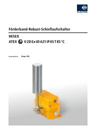
3.1 How the emergency stop function<br />
works for all types<br />
The trigger lever (3) for the PRS pull-rope emergency<br />
stop switch is actuated via a tear rope (15) which is stretched<br />
along the conveyor system (see fig. 3-1).<br />
Attachment point for anchor<br />
hooks (20)<br />
Reset lever (4)<br />
!<br />
Warning!<br />
The tear rope should be stretched along the conveyor<br />
system so that it is visible along its entire length.<br />
Actuating the trigger lever (3) causes the switch cylinder<br />
to move to the “Off” position, so that the trigger lever (3)<br />
is decoupled. At this point, no further switching operation<br />
is possible. When inserting a pull-rope emergency stop<br />
Trigger lever (3)<br />
Attachment point for<br />
anchor hooks (20)<br />
Signal lamp (9)<br />
Tension spring (16)<br />
Tear rope (15)<br />
Tear rope (15)<br />
Tension spring (16)<br />
Max. 50 m<br />
Max. 50 m<br />
Abb. 3-1:<br />
Function<br />
Operating Instructions<br />
PRS
10<br />
3 Description<br />
switch with signal lamp (9), it displays the emergency<br />
stop status.<br />
The tear rope length (15) may vary according to local<br />
conditions; however, it must not exceed 50 m on either<br />
side. The tension springs (16) at both ends of the tear<br />
rope (15) ensure that the tear rope is foolproof, i.e. if the<br />
tear rope (15) is broken, the pull-rope emergency stop<br />
switch is actuated by the tension spring (16).<br />
!<br />
Warning!<br />
After actuating and before resetting the pull-rope emergency<br />
stop switch, the installation must be checked<br />
along the entire length of the tear rope (15) in order to<br />
establish why the pull-rope emergency stop switch was<br />
actuated.<br />
The conveyor system can only be restarted if the reset lever<br />
(4) has been used to unlock the pull-rope emergency<br />
stop switch at the installation site.<br />
CONFIDENTIAL<br />
PRS<br />
Operating Instructions
4 Technical data<br />
11<br />
4 Technical data<br />
4.1 General technical data<br />
CONFIDENTIAL<br />
In compliance with the following standards<br />
and regulations<br />
EN 60947-5-1, EN 60947-5-5, EN 0418,<br />
VDE 0110 – degree of pollution: 2 (inside), 4 (outside), VBG 10/BGI 710<br />
Suitable for Controls and installations according to EN 60204<br />
Version<br />
Plastic (casing: yellow (RAL 1004), trigger lever: red (RAL 3000) and reset lever: blue<br />
(similar to RAL 5010)<br />
Mounting 2 screws M 6<br />
Permissible ambient temperature -25°C – +70°C<br />
Switching system<br />
PRS 001<br />
2 snap-acting switches with forced opening for emergency stop circuits (orange terminals)<br />
PRS 101<br />
1 snap-acting switch as normally open contact for the signal lamp<br />
Rated insulation voltage U i<br />
AC 230 V<br />
Rated operating voltage U e<br />
AC 230 V<br />
Conventional thermal current I th 6 A<br />
Breaking capacity<br />
AC -15<br />
DC-13<br />
Protection standard<br />
according to DIN VDE 470, part 1 (EN<br />
60529)<br />
Mechanical service life<br />
AC 230 V, 1.5 A<br />
DC 60 V / 0.5 A<br />
IP 67<br />
10.000 switching cycles<br />
Operating Instructions<br />
PRS
12<br />
4 Technical data<br />
Conductor infeed Threaded hole for 3 x M 25 x 1.5<br />
1x screwed cable gland M 25 x 1.5; sealing area Ø 9 mm to Ø 17 mm<br />
2 x dummy plug M25 x 1.5<br />
Line connection cross-section Max. 2.5 mm 2<br />
4.2 Technical data – PRS 101 with signal lamp<br />
Rated operating voltage of the signal<br />
lamp<br />
AC 230 V<br />
(at terminals X14 and X15)<br />
CONFIDENTIAL<br />
PRS<br />
Operating Instructions
4 Technical data<br />
13<br />
4.3 Dimensions<br />
CONFIDENTIAL<br />
126<br />
113,5<br />
68,5<br />
95 175<br />
80,5<br />
Ø 6<br />
54<br />
162<br />
Abb. 4-1:<br />
Dimensions<br />
Operating Instructions<br />
PRS
14<br />
5 Mounting and dismounting<br />
5 Mounting and dismounting<br />
5.1 Scope of delivery<br />
The pull-rope emergency stop switches are delivered<br />
ready to operate. The screws for mechanical fastening<br />
are not included in the scope of delivery. One cable gland<br />
(10) and two dummy plugs (11) are included in the scope<br />
of delivery (see fig. 5-1).<br />
!<br />
Beware!<br />
Use only screwed cable glands and dummy plugs recommended<br />
by the manufacturer and supplied with the<br />
device.<br />
Abb. 5-1:<br />
Thread (M 25 x 1.5) for 1 cable<br />
gland (10) and 2 dummy plugs<br />
(11)<br />
Scope of delivery<br />
5.2 Mounting<br />
!<br />
Beware!<br />
The device must only be operated when all three holes<br />
are closed with the supplied cable gland (10) and both<br />
dummy plugs (11). Only use the supplied cable gland<br />
(10) and dummy plugs (11), otherwise the seal can no<br />
longer be guaranteed.<br />
5.2.1 Important mounting instructions<br />
Observe the following notes while mounting to ensure<br />
that the pull-rope emergency stop switches are operated<br />
properly. If conditions should deviate from those indicated,<br />
consult Vossloh <strong>Kiepe</strong> GmbH (see legal notice for<br />
company address).<br />
When mounting, only use KIEPE accessories. This applies<br />
in particular to the cable gland (10) and the dummy<br />
plug (11).<br />
• Mount at an ambient temperature of approx + 15°C.<br />
• The pull-rope emergency stop switch must be mounted<br />
in the middle between the attachment points.<br />
Deviation of up to 3 % of the distance between the<br />
CONFIDENTIAL<br />
PRS<br />
Operating Instructions
5 Mounting and dismounting<br />
15<br />
pull-rope emergency stop switch and the attachment<br />
point is permitted.<br />
• The distance between the attachment points may<br />
not exceed 100 m.<br />
• The attachment points for the anchor hooks (20)<br />
must be constructed from sturdy mechanical components.<br />
• The distance between the eyebolts (19) must not<br />
exceed 2.5 m (see figure 5-2, page 16).<br />
• Egg-shaped clamps (18)<br />
• Eyebolts (19) M 12 x 60<br />
• Anchor hooks (20) M 10<br />
CONFIDENTIAL<br />
5.2.2 KIEPE mounting accessories<br />
Pull-rope emergency stop switches must be fastened<br />
into place on the conveyor structure using KIEPE accessories.<br />
You will require the following accessories to mount the<br />
pull-rope emergency stop switch (see figure 5-4, page<br />
17)):<br />
• two M 6 screws (5) for securing the pull-rope emergency<br />
stop switch into place (see figure 5-3, page<br />
17)<br />
• Cable gland (10), M 25 x 1.5 (see figure 5-8, page<br />
22)<br />
• A tear rope (15) made of red, flexible steel wire,<br />
plastic coated, Ø 3 mm<br />
• Tension springs (16), 170 x Ø 20 mm<br />
• Turnbuckles (17)<br />
Operating Instructions<br />
PRS
16<br />
5 Mounting and dismounting<br />
5.2.3 Mechanical mounting<br />
Danger of fatal electric shock<br />
Work on the device may be performed only by a qualified<br />
electrical technician.<br />
Prior to working, switch off the power supply to the system.<br />
Ensure that the system cannot be accidentally<br />
switched on. Mask any neighboring components that<br />
may be live to prevent contact.<br />
!<br />
Warning!<br />
The tear rope should be stretched along the conveyor<br />
system so that it is visible along its entire length.<br />
!<br />
Beware!<br />
The pull-rope emergency stop switches may be used in<br />
control circuits only.<br />
Egg-shaped clamp (18)<br />
Eyebolts (19)<br />
Distance: max. 2.5 m<br />
Reset lever (4)<br />
1. Prior to working, switch off the power supply to the<br />
system. Ensure that the conveyor system cannot be<br />
Trigger lever (3) Egg-shaped clamp (18)<br />
Eyebolts (19)<br />
Distance: max. 2.5 m<br />
CONFIDENTIAL<br />
Tension spring<br />
Tension spring Tear rope (15)<br />
Tear rope (15)<br />
(16)<br />
(16)<br />
Turnbuckle<br />
Turnbuckle<br />
Rope loop (21) (17)<br />
(17)<br />
Rope loop (21)<br />
Attachment point for rope loop (21) Attachment point for rope loop (21)<br />
max. 50 m (± 3 %)<br />
max. 50 m (± 3 %)<br />
Abb. 5-2:<br />
Mounting on the conveyor structure<br />
PRS<br />
Operating Instructions
5 Mounting and dismounting<br />
17<br />
CONFIDENTIAL<br />
accidentally switched on. Mask any neighboring<br />
components that may be live to prevent contact.<br />
2. Secure the pull-rope emergency stop switch in the<br />
middle between the attachment points on the conveyor<br />
structure (see figures 4-1 and 5-2). In doing<br />
so, the actuating lever (3) must point towards the<br />
belt. Secure the pull-rope emergency stop switch<br />
with two screws M 6 (5) through the sockets (13)<br />
(see fig. 5-3).<br />
Trigger lever (3)<br />
Belt side<br />
Socket (13) for<br />
screws M 6 (5)<br />
!<br />
Beware!<br />
The attachment points for the anchor hooks (20) must<br />
be constructed from sturdy mechanical components,<br />
which the anchor hooks (20) cannot break away from<br />
when actuating the tear rope (15).<br />
3. Place the anchor hooks (20) on the attachment<br />
points (see fig. 5-2).<br />
4. Hook the tension springs (16) onto the anchor hook<br />
(20) (see fig. 5-4).<br />
Anchor hooks (20)<br />
Tension spring<br />
(16)<br />
Tear rope (15)<br />
max. 400 mm + 170 mm<br />
Egg-shaped clamp (18)<br />
Socket (13) for<br />
screws M 6 (5)<br />
Reset lever (4)<br />
Allow 450 to 500 mm of the tear<br />
rope (15) for the rope loop (21)<br />
Abb. 5-3:<br />
Mounting the pull-rope emergency stop switch<br />
Abb. 5-4:<br />
Attaching the tear rope onto the tension spring<br />
Operating Instructions<br />
PRS
18<br />
5 Mounting and dismounting<br />
5. Thread the end of the tear rope (15) through the eye<br />
of the tension spring (16). Pull the tear rope (15)<br />
about 450 to 500 mm through the eye, so that it can<br />
form a rope loop (21) at that end to complete the<br />
mounting procedure (see fig. 5-4).<br />
Note<br />
The rope loops (21) are designed to limit the actuating<br />
travel of the tear rope (15) when actuated<br />
and prevents the tension springs (16) from<br />
overextending. The maximum extension of a<br />
tension spring (16) is approximately 400 mm.<br />
Egg-shaped clamp (18)<br />
Eyebolts (19)<br />
Distance: max. 2.5 m<br />
Reset lever (4)<br />
6. Secure the tear rope (15) on the tension spring (16)<br />
using an egg-shaped clamp (18) (see fig. 5-4).Fix<br />
the eyebolts (19) to the conveyor structure to guide<br />
the tear rope (15) (see fig. 5-5).<br />
Distance between eyebolts (19): max. 2.5 m<br />
7. Put the tear rope (15) through the eyebolts (19) (see<br />
fig. 5-5).<br />
Setting the spring force<br />
Centering the trigger lever (3) makes it resistant to temperature<br />
changes. The tension springs (16) compensate<br />
for any extension or contraction of the tear rope (15)<br />
caused by temperature changes (see fig. 5-5).<br />
Trigger lever (3) Egg-shaped clamp (18)<br />
Eyebolts (19)<br />
Distance: max. 2.5 m<br />
CONFIDENTIAL<br />
Tension spring<br />
Tension spring Tear rope (15)<br />
Tear rope (15)<br />
(16)<br />
(16)<br />
Turnbuckle<br />
Turnbuckle<br />
Rope loop (21) (17)<br />
(17)<br />
Rope loop (21)<br />
Attachment point for rope loop (21) Attachment point for rope loop (21)<br />
max. 50 m (± 3 %)<br />
max. 50 m (± 3 %)<br />
Abb. 5-5:<br />
Mounting on the conveyor structure and setting the spring force<br />
PRS<br />
Operating Instructions
5 Mounting and dismounting<br />
19<br />
CONFIDENTIAL<br />
!<br />
Beware!<br />
If the tear rope tears on one side, the pull-rope emergency<br />
stop switch must be actuated by the tension<br />
spring on the other side.<br />
8. Release the tension of the turnbuckle (17) completely<br />
(see fig. 5-6).<br />
9. Put one end of the tear rope (15) through the eye of<br />
the turnbuckle (17) and hook the turnbuckle (17) into<br />
the trigger lever (3) (see fig. 5-6).<br />
!<br />
Beware!<br />
The tear rope (15) may be maximum 50 meters long in<br />
each direction.<br />
10. Tighten the tear rope (15) so that the tension spring<br />
(16) is extended by 35 mm (see fig. 5-5).<br />
11. Attach this end of the tear rope (15) using an eggshaped<br />
clamp (18) (see fig. 5-6).<br />
12. Remove the turnbuckle (17) again. Unlock the pullrope<br />
emergency stop switch by using the reset lever<br />
(4) (see fig. 5-5).<br />
13. Repeat steps 5 - 12 for installing the tear rope (15)<br />
on the other side of the pull-rope emergency stop<br />
switch (see fig. 5-5).<br />
14. Now hook both turnbuckles (17) into place and operate<br />
the actuating lever (3) of the pull-rope emergency<br />
stop switch (see fig. 5-5).<br />
The trigger lever (3) can now be moved.<br />
15. Place the actuating lever (3) in the middle using the<br />
turnbuckles (17) and adjust the tightened tension<br />
springs (16) so that they are 210 mm long (see<br />
fig. 5-5).<br />
Trigger lever (3) Turnbuckle (17) Tear rope (15)<br />
Abb. 5-6:<br />
Reset lever (4)<br />
Egg-shaped clamp (18)<br />
Mounting the pull-rope emergency stop switch<br />
Operating Instructions<br />
PRS
20<br />
5 Mounting and dismounting<br />
Anchor hooks (20)<br />
50 mm<br />
Anchor hooks (20)<br />
Tension spring<br />
(16)<br />
Tear rope (15)<br />
Egg-shaped clamp (18)<br />
Rope loop (21)<br />
Tension spring<br />
(16)<br />
Egg-shaped clamp (18)<br />
Rope loop (21)<br />
Tear rope (15)<br />
!<br />
Beware!<br />
Ensure that rope loops are formed on both tension<br />
springs.<br />
The rope loops are designed to limit the actuating travel<br />
of the tear rope and prevent the tension springs from<br />
overextending (see figure 5-7, page 20). The maximum<br />
extension of a tension spring is approximately 400 mm.<br />
16. Form the rope loops (21) on both tension springs<br />
(16) as follows:<br />
a. place the section of tear rope (15) provided for<br />
the rope loop (21) along the tension spring (16)<br />
(See figure 5-7, above).<br />
b. Use the end of the rope loop (21) to make a fastening<br />
loop that stops about 50 mm from the end<br />
of the tension spring (16) (See figure 5-7,<br />
above).<br />
c. Use an egg-shaped clamp (18) to attach the<br />
rope loop (21) to the anchor hook (20) (See<br />
figure 5-7, below).<br />
CONFIDENTIAL<br />
Abb. 5-7:<br />
Forming the rope loop<br />
PRS<br />
Operating Instructions
5 Mounting and dismounting<br />
21<br />
CONFIDENTIAL<br />
5.2.4 Electrical connection 5.2.4.1 Preparation work<br />
Danger of fatal electric shock<br />
Work on the device may be performed only by a qualified<br />
electrical technician.<br />
Prior to working, switch off the power supply to the system.<br />
Ensure that the system cannot be accidentally<br />
switched on. Mask any neighboring components that<br />
may be live to prevent contact.<br />
!<br />
Danger!<br />
The penetration of dust and moisture into the pull-rope<br />
emergency stop switch must be prevented at all costs.<br />
As required, remove any dust which has entered the<br />
unit. Seal the cover immediately after making the electrical<br />
connection.<br />
!<br />
Danger!<br />
Only use connection cables with a diameter of between<br />
11 mm and 16 mm. The permissible conductor crosssections<br />
can be found in Chapter 4: „Technical data",<br />
page 11.<br />
1. Prior to working, switch off the power supply to the<br />
system. Ensure that the conveyor system cannot be<br />
accidentally switched on. Mask any neighboring<br />
components that may be live to prevent contact.<br />
2. Open the cover (2) of the belt pull-rope emergency<br />
stop switch by unscrewing the two screws (6) (see<br />
fig. 5-8).<br />
!<br />
Beware!<br />
The device must only be operated when all three holes<br />
are closed with the supplied cable gland (10) and both<br />
dummy plugs (11). Only use the supplied cable gland<br />
(10) and dummy plugs (11), otherwise the seal can no<br />
longer be guaranteed.<br />
3. Turn the cable gland (10) into one of the threaded<br />
holes M 25 x 1.5 of the pull-rope emergency stop<br />
switch.<br />
4. Close the other two holes with the dummy plugs (11)<br />
5. Pull the connection cable through the cable gland<br />
(10).<br />
Operating Instructions<br />
PRS
22<br />
5 Mounting and dismounting<br />
5.2.4.2 Connecting types PRS 001 and PRS 101<br />
1. Connect the connection cable to the connection terminals<br />
(8) according to the connection diagram:<br />
PRS 001 without signal lamp (9):<br />
See figure 5-9<br />
PRS 101 with signal lamp (9): See figure 5-10<br />
2. Close the cover (2) of the belt pull-rope emergency<br />
stop switch, and tighten both screws again (6) (see<br />
fig. 5-8).<br />
PRS 001 without signal lamp<br />
10 11 12 13 14 15 16 17 18 19<br />
21 22<br />
Cover (2)<br />
Screw M 6 (5)<br />
Thick lines: Circuit for the PRS 001.<br />
Auxiliary signal circuit:<br />
connection terminal (8)<br />
X16 … X18 (gray)<br />
CONFIDENTIAL<br />
Screws (6)<br />
Screw M 6 (5)<br />
Thread (M 25 x 1.5) for 1 cable<br />
gland (10) and 2 dummy<br />
plugs (11)<br />
Emergency stop circuit:<br />
connection terminal (8)<br />
X10 … X13 (orange)<br />
Abb. 5-8:<br />
Pull-rope emergency stop switch connection<br />
Abb. 5-9:<br />
Assignment of the connection terminals of the<br />
PRS 001<br />
PRS<br />
Operating Instructions
5 Mounting and dismounting<br />
23<br />
PRS 101 with signal lamp<br />
5.3 Dismounting<br />
10 11 12 13 14 15 16 17 18 19<br />
21 22<br />
Danger of fatal electric shock<br />
Work on the device may be performed only by a qualified<br />
electrical technician.<br />
Prior to working, switch off the power supply to the system.<br />
Ensure that the system cannot be accidentally<br />
switched on. Mask any neighboring components that<br />
may be live to prevent contact.<br />
CONFIDENTIAL<br />
Thin lines: additional circuit for the PRS 101.<br />
Auxiliary signal circuit:<br />
connection terminal (8)<br />
X16 … X19, X21 … X22 (gray)<br />
Danger of fatal electric shock<br />
Prior to dismounting, ensure that the conveyor system<br />
is de-energized. Ensure that the unit cannot be accidentally<br />
switched on.<br />
Abb. 5-10: Assignment of the connection terminals of the<br />
PRS 101<br />
Operating Instructions<br />
Signal lamp (AC 230 V): connection<br />
terminals X14, X15<br />
(gray)<br />
Connection terminal (8)<br />
X10 … X13 (orange)<br />
Danger of fatal electric shock<br />
Open the pull-rope emergency stop switch only after it<br />
has been de-energized.<br />
1. Prior to working, switch off the power supply to the<br />
system. Ensure that the conveyor system cannot be<br />
accidentally switched on. Mask any neighboring<br />
components that may be live to prevent contact.<br />
PRS
24<br />
5 Mounting and dismounting<br />
2. Open the cover (2) of the belt pull-rope emergency<br />
stop switch by unscrewing the two screws (6) (see<br />
fig. 5-11).<br />
3. Unscrew the cable gland (10).<br />
4. Disconnect all electrical connections and pull the<br />
cables out of the cable gland (10) (see figure 5-9,<br />
page 22).<br />
5. Unscrew both screws M 6 (5), and remove the<br />
device (see fig. 5-11).<br />
Cover (2)<br />
Screw M 6 (5)<br />
CONFIDENTIAL<br />
Screw M 6 (5)<br />
Screws (6)<br />
Thread (M 25 x 1.5) for 1 cable<br />
gland (10) and 2 dummy<br />
plugs (11)<br />
Abb. 5-11: Dismounting the pull-rope emergency stop switch<br />
PRS<br />
Operating Instructions
6 Maintenance and repair<br />
25<br />
6 Maintenance and repair<br />
1. Check the pull-rope emergency stop switch and the<br />
tear rope system at regular intervals (approximately<br />
every three months) to ensure that they are in proper<br />
condition and function smoothly.<br />
!<br />
Danger!<br />
A damaged pull-rope emergency stop switch or damaged<br />
components (e.g. cable glands, gaskets) are not to<br />
be used.<br />
Damaged pull-rope emergency stop switches must always<br />
be replaced<br />
CONFIDENTIAL<br />
Egg-shaped clamp (18)<br />
Eyebolts (19)<br />
Distance: max. 2.5 m<br />
Reset lever (4)<br />
Trigger lever (3) Egg-shaped clamp (18)<br />
Eyebolts (19)<br />
Distance: max. 2.5 m<br />
Tension spring<br />
Tension spring Tear rope (15)<br />
Tear rope (15)<br />
(16)<br />
(16)<br />
Turnbuckle<br />
Turnbuckle<br />
Rope loop (21) (17)<br />
(17)<br />
Rope loop (21)<br />
Attachment point for rope loop (21) Attachment point for rope loop (21)<br />
max. 50 m (± 3 %)<br />
max. 50 m (± 3 %)<br />
Abb. 6-1:<br />
Mounting on the conveyor structure and setting the spring force<br />
Operating Instructions<br />
PRS
26<br />
7 Ordering devices, replacement parts and accessories<br />
7 Ordering devices, replacement parts and accessories<br />
7.1 Ordering devices<br />
Please provide the following data with every order (see<br />
legal notice for company address):<br />
1. Pull-rope emergency stop switch type<br />
(see rating plate on casing cover):<br />
e.g. PRS 001<br />
2. Product number<br />
(see rating plate on casing cover):<br />
e.g. 91.054 033.001<br />
Type of pull-rope emergency stop Product number<br />
switch<br />
PRS 001 (without signal lamp) 91.054 033.001<br />
PRS 101 (with signal lamp) 91.054 033.101<br />
CONFIDENTIAL<br />
PRS<br />
Operating Instructions
7 Ordering devices, replacement parts and accessories<br />
27<br />
CONFIDENTIAL<br />
7.2 Ordering replacement parts and<br />
accessories<br />
Please provide the following data with every order (see<br />
legal notice for company address):<br />
1. Pull-rope emergency stop switch type<br />
(see rating plate on casing cover):<br />
e.g. PRS 001<br />
2. Product number<br />
(see rating plate on casing cover):<br />
e.g. 91.054 033.001<br />
3. Order information and order number (see table):<br />
e.g. eye bolts M 12 x 60, 94.045 727.001<br />
Egg-shaped clamp (18)<br />
Eyebolts (19)<br />
Eyebolts (19)<br />
Egg-shaped clamp (18)<br />
Tension spring (16) Tear rope (15)<br />
Tear rope (15) Tension spring (16)<br />
Turnbuckle (17)<br />
Turnbuckle (17)<br />
Anchor hooks (20) Anchor hooks (20)<br />
Abb. 7-1:<br />
Accessories<br />
Operating Instructions<br />
PRS
28<br />
7 Ordering devices, replacement parts and accessories<br />
Tear rope (15)<br />
Turnbuckle (17)<br />
Item Order information Order number<br />
19 Eyebolt<br />
M 12 x 60<br />
M 12 x 200<br />
94.045 727.001<br />
94.045 727.002<br />
20 Anchor hook M 10 94.045 728.001<br />
Egg-shaped clamp (18)<br />
Abb. 7-2:<br />
Accessories<br />
Item Order information Order number<br />
15 Tear rope red, flexible steel wire,<br />
plastic coated Ø 3 mm<br />
Roll 50 m<br />
Roll 100 m<br />
Roll 500 m<br />
94.045 731.001<br />
94.045 731.011<br />
94.045 731.021<br />
94.045 731.031<br />
16 Tension spring V2A<br />
170 mm x Ø 20 mm 94.000 026.681<br />
17 Turnbuckle (metal, 1 hook, 1 eye) 215.22.80.02.01<br />
18 Egg-shaped clamp<br />
for tear rope of Ø 3 mm 94.047 869.001<br />
CONFIDENTIAL<br />
PRS<br />
Operating Instructions
29<br />
CONFIDENTIAL<br />
Operating Instructions<br />
PRS
www.vossloh-kiepe.com Vossloh <strong>Kiepe</strong> GmbH<br />
<strong>Kiepe</strong>-Platz 1<br />
40599 Düsseldorf<br />
Tel.: +49(0)211/7497–0<br />
Fax: +49 (0) 211 / 74 97 – 420<br />
Germany