Betriebsanleitung - Kiepe Elektrik
Betriebsanleitung - Kiepe Elektrik
Betriebsanleitung - Kiepe Elektrik
- No tags were found...

You also want an ePaper? Increase the reach of your titles
YUMPU automatically turns print PDFs into web optimized ePapers that Google loves.
62 Transport, packaging, storage and disposal2 Transport, packaging, storage and disposal2.1 Transport and packagingBe sure to use suitable packaging when sending thedevice or components to Vossloh <strong>Kiepe</strong> GmbH (e.g. forrepairs). Take extra precautions to ensure that thedevice is shock-proof and moisture-proof. By doing so,you will avoid damage to the device for which themanufacturer assumes no liability.2.2 StorageAvoid major temperature fluctuations as these can leadto water condensation, which can cause damage to thedevice.Allowable storage temperature ranges from -25°C to+75°C.BewareIf it has been in storage for approximately ayear, the SWE-compact electronic speedmonitor must be connected several timesbefore being put into operation.2.3 DisposalOnly materials are used for Vossloh <strong>Kiepe</strong> GmbHproducts which are not considered hazardous materialsin compliance with the latest standards. Furthermore,we develop products that can be recycled after intendeduse. In our selection of raw materials and components,we favor reusable materials. This choice of materialsused does not compromise product safety in any way.BewareProtect the device from dirt and moisture.SWE-compact Operating Instructions
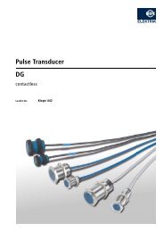
283 Construction and function73 Construction and functionSWE-compact electronic speed monitors directlymonitor the speed of the belt. To this end, the speedmonitors are attached directly to the drum beingmonitored. The electronic speed monitors can be usedfor monitoring insufficient revolutions, to check forslippage and to monitor standstills.3.1 Construction“Setpoint adjustment”potentiometer (10)HOCHLAUFÜBERBRÜCKUNGSCHALTPUNKTEINSTELLUNGIn the device, the opto-electronic impulse transmitter,SWEthe speed analysis relay and the power supply unit are230V 50…60HzSETPOINTADJUSTMENTBgrouped together as one unit. The device has aMADE IN GERMANY A1 A215 16 18separate connection area, housing the connectionterminals (7), the potentiometers (9, 10) for switch pointadjustment and for the start-up bypass, and the red LED(41) for displaying the operating state.The K1 (12) or K7 (13) couplings are used to connectthe device to the drum being monitored (see Fig. 5-2and 5-3). The K1 coupling (12) enables the device to berigidly connected to the drum, whereas the bellow (24) inthe K7 coupling (13) allows for a flexible connection.There are various different attachments available forconnecting the device to the conveyor system (seesection 9.3 "Ordering accessories"). Fig. 3-1: SWE-compact speed monitor130405“Start-up delay”potentiometer (9)6START UPDELAY7109Connectionterminals (7)LED (41)SWE-compact Operating Instructions
4 Technical data11266,6Ø 80Ø 70135120Fig. 4-2:Dimensions of SWE-compact with F1 fastening flange (in mm)SWE-compact Operating Instructions
4 Technical data1311012887512712,5 45104Fig. 4-4:Dimensions of SWE-compact with F4 mounting foot (in mm)SWE-compact Operating Instructions
144 Technical dataPlastic coupling, flexible, polyamide, resistant to allmineral oils, weatherproofTemperature resistance: approx. - 40 °C to + 110 °CAlignment error: max. 3 mm28 602350M8Ø4820Fig. 4-5:Assembly drawing for K1 coupling (in mm)SWE-compact Operating Instructions
4 Technical data15Flexible bellow coupling for external shaft offsetTemperature resistance: approx. - 45 °C to + 100 °C (up to + 130 °C for short periods)Alignment error: max. 10 mm28 642362M813Fig. 4-6:Assembly drawing for K7 coupling (in mm)SWE-compact Operating Instructions
165 Mounting and removal5 Mounting and removal5.1 Scope of deliverySWE-compact electronic speed monitors are deliveredready to operate. A screwed cable gland (5), a dummyplug (6) and a sealing washer (30) for assembly areincluded. The screws for mechanical fastening are notincluded in the scope of delivery (see Fig. 5-1).Dummy plug (6) Screwed cable gland (5)Various different couplings and fasteners are availableas accessories for mounting the device to the conveyorsystem (for ordering information, see (see chapter 9,"Ordering devices, replacement parts and accessories").5.2 MountingDanger of fatal electric shock!The device should be mounted andelectrically connected by a qualifiedelectrical technician only.Prior to mounting, switch off the powersupply to the conveyor system. Ensure thatthe conveyor system cannot be accidentallyswitched on. Mask any neighboringcomponents that may be live to preventcontact.SWE-compactSealing washer (30)Fig. 5-1:Scope of deliverySWE-compact Operating Instructions
5 Mounting and removal175.2.1 Mechanical Mounting5.2.1.1 Mounting the K1 and K7 couplingsMounting the K1 coupling1. Screw the connecting shaft (14) together with thelock washer (15) into the conveyor system's driveshaft (for the installation dimensions, see Fig. 4-5).2. Slide the toothed wheel (16) onto the connectingshaft (14) and secure the toothed wheel (16) with theM 5 x 6 threaded pin (19).BewareYou must not force the toothed wheel (17)against the speed monitor's shaft (4)! Merelypress the toothed wheel (17) against theshaft (4).3. Slide the toothed wheel (17) onto the speedmonitor's shaft (4) and secure the toothed wheel (17)with the M 5 x 6 threaded pin (19).4. Attach the coupling sleeve (18) onto the toothedwheel (17).Lock washer (15)Connecting shaft (14)M 5 x 6 threadedpin (19)Shaft (4)Conveyorsystem's driveshaftK1 coupling (12)Toothed wheel (16) Coupling sleeve (18) Toothed wheel (17)Casing (1) for theSWE-compactelectronic speedmonitorFig. 5-2:SWE-compact electronic speed monitor – mounting the K1 couplingSWE-compact Operating Instructions
185 Mounting and removalMount the SWE-compact electronic speedmonitor to the conveyor system in such a waythat the distance between the speed monitor'scasing (1) and the drive shaft is approximately60 mm (for the installation dimensions, see Fig.4-5).5. Insert the speed monitor into the installation space insuch a way that you attach the coupling sleeve (18)onto the toothed wheel (16) on the connecting shaft(14).6. Mount the electronic speed monitor on the conveyorsystem (see section 5.2.1.2 "Mounting on theConveyor System").Mounting the K7 coupling1. Use the M 8 x 30 hex cap screw (22) and the detentedged ring (23) to screw the hub (20) onto theconveyor system's drive shaft.2. Slide the hub (21) onto the electronic speedmonitor's shaft (4) and secure the hub (21) with theM 5 x 6 threaded pin (19).M 8 x 30 hex capscrew (22) with detentedged ring (23)Hub (20)Bellow (24)Hub (21)M 5 x 6 threaded pin (19)Shaft (4)Conveyorsystem's driveshaftK7 coupling (13)Cable tie (25)Casing (1) for theSWE-compactelectronic speedmonitorFig. 5-3:SWE-compact electronic speed monitor – mounting the K7 couplingSWE-compact Operating Instructions
5 Mounting and removal193. Place the bellow (24) on the hub (21) and secure thebellow (24) with a cable tie (25). Cut off the excessend of the cable tie (25).Mount the electronic speed monitor to theconveyor system in such a way that the distancebetween the speed monitor's casing (1) and thedrive shaft is approximately 64 mm (for theinstallation dimensions, see Fig. 4-6).4. Insert the speed monitor into the installation space insuch a way that you can attach the bellow (24) ontothe hub (20) on the drive shaft.5. Mount the electronic speed monitor on the conveyorsystem (see section 5.2.1.2 "Mounting on theConveyor System").6. Secure the bellow (24) with the second cable tie (25)and cut off the excess end of the cable tie (25).5.2.1.2 Mounting on the Conveyor SystemMounting the SWE-compact electronic speedmonitorMount the SWE-compact electronic speed monitor onthe conveyor system using four suitable M 6 screws andthe supplied sealing washer (30) (for the installationdimensions, see Fig. 4-1).Dummy plug (6) Screwed cable gland (5)M6SWE-compactSealing washer (30)Fig. 5-4:Mounting the SWE-compact electronic speedmonitorSWE-compact Operating Instructions
205 Mounting and removalMounting with fastening flange F11. Use the four M 6 x 16 countersunk screws (29) andthe supplied sealing ring (30) to mount the F1fastening flange (26) on the SWE-compact electronicspeed monitor.2. Place the gasket (33) in the F1 fastening flange'sgroove (26).3. Use four suitable M 6 screws to mount the speedmonitor to the F1 fastening flange (26) on theconveyor system (for the installation dimensions, seeFig. 4-2).Mounting with fastening flange F21. Preassemble the K1 coupling (12) (see “Mountingthe K1 coupling”, steps 1. to 4.).2. Use the four M 6 x 26 hex cap screws (31), thedetent edged rings (32) and the supplied sealing ring(30) to mount the F2 fastening flange (27) on theSWE-compact electronic speed monitor.3. Insert the speed monitor with the F2 fastening flange(27) into the installation space in such a way that youplace the coupling sleeve (18) on the toothed wheel(16) on the connecting shaft (14).F1 fasteningflange (26)M6x16countersunkscrew (29)Sealing washer (30)F2 fasteningflange (27)Connectingshaft (14)Sealing washer (30)Fig. 5-5:Gasket (33)Mounting the SWE-compact electronic speedmonitor with fastening flange F1Fig. 5-6:Toothed wheel (16)Coupling sleeve (18)M 6 x 26 hex cap screw (31) withdetent edged ring (32)Mounting the SWE-compact electronic speedmonitor with fastening flange F2SWE-compact Operating Instructions
5 Mounting and removal214. Use four suitable M 6 screws to mount the electronicspeed monitor to the F2 fastening flange (27) on theconveyor system (for the installation dimensions, seeFig. 4-3).Mounting with mounting foot F41. Use the four M 6 x 26 hex cap screws (31), thedetent edged rings (32) and the supplied sealing ring(30) to mount the F4 mounting foot (28) on the SWEcompactelectronic speed monitor.The F4 mounting foot (28) can point forwards orbackwards.Sealing washer (30)M 6 x 26 hex capscrew (31) with detentedged ring (32)F4 mountingfoot (28)2. Fasten four suitable M 8 screws through the slottedholes on the conveyor system to mount the electronicspeed monitor to the F4 mounting foot (28) (for theinstallation dimensions, see Fig. 4-4).5.2.2 Electrical connectionDanger of fatal electric shock!The device should be electrically connectedby a qualified electrical technician only.Prior to connecting, switch off the powersupply to the conveyor system. Ensure thatthe conveyor system cannot be accidentallyswitched on. Mask any neighboringcomponents that may be live to preventcontact.1. Unscrew the two locking screws (3) and remove thecover (2) (see Fig. 5-8).2. Unscrew the screwed cable gland (5) and feed theconnection cable through the screwed cable gland(5).Fig. 5-7:Mounting the SWE-compact electronic speedmonitor with mounting foot F4SWE-compact Operating Instructions
218225 Mounting and removalBewareThe electronic speed monitor must alwaysbe switched on and off using the tractiondrive being monitored (the conveyorsystem).3. Connect the connection cable to the connectionterminals (7) (see Fig. 5-9 and 5-10).4. Screw the screwed cable gland (5) tight.5. Place the cover (2) on the electronic speed monitor'scasing (1) and close the cover (2) by tightening thelocking screws (3).Lockingscrews (3)SWE0HOCHLAUFÜBERBRÜCKUNGSCHALTPUNKTEINSTELLUNG230V 50…60Hz30456START UPDELAY7109BSETPOINTADJUSTMENTCover (2)Casing (1)MADE IN GERMANYA1A216 15 18Casing (1)Connectionterminals (7)Screwed cable gland (5)Screwed cable gland (5)Fig. 5-8:Connecting the SWE-compact electronic speedmonitorFig. 5-9: SWE-compact electronic speed monitor –connection areaSWE-compact Operating Instructions
5 Mounting and removal23L1OffOnK1K1A1 15SWEA21618K1L2Motor protectionH1Malfunction displayFig. 5-10:Electrical connection – circuit exampleSWE-compact Operating Instructions
218245 Mounting and removal5.3 RemovalDanger of fatal electric shockThe device should be removed andelectrically connected by a qualifiedelectrical technician only.Prior to removal, ensure that the conveyorsystem is de-energized. Ensure that theconveyor system cannot be accidentallyswitched on. Mask any neighboringcomponents that may be live to preventcontact.1. Unscrew the two locking screws (3) and remove thecover (2).2. Detach the connection cable from the connectionterminals (7).3. Unscrew the screwed cable gland (5) and removethe connection cable from the screwed cable gland(5).Lockingscrews (3)SWE0HOCHLAUFÜBERBRÜCKUNGSCHALTPUNKTEINSTELLUNG230V 50…60Hz30456START UPDELAY7109BSETPOINTADJUSTMENTCover (2)Casing (1)MADE IN GERMANYA1A216 15 18Casing (1)Connectionterminals (7)Screwed cable gland (5)Screwed cable gland (5)Fig. 5-11:SWE-compact electronic speed monitor – removalFig. 5-12:Disconnecting the SWE-compact electronic speedmonitorSWE-compact Operating Instructions
5 Mounting and removal254. Place the cover (2) on the electronic speed monitor'scasing (1) and close the cover (2) by tightening thelocking screws (3).If using the K1 coupling:1. Unscrew the mounting bolts that attach the speedmonitor to the conveyor system.2. Remove (as applicable) fastening flange F1 (26),fastening flange F2 (27) or mounting foot F4 (28), byremoving the four M 6 x 16 countersunk screws (29)or the four M 6 x 26 hex cap screws (31) (see Fig. 5-5 to5-7).3. Remove the coupling sleeve (18) from the toothedwheel (17).4. Detach each of the M 5 x 6 threaded pins (19) andremove the toothed wheels (16 and 17) from theshaft (4) and the connecting shaft (14).5. Unscrew the connecting shaft (14) from the conveyorsystem's drive shaft.6. Remove the lock washer (15).Lock washer (15)Connecting shaft (14)M 5 x 6 threadedpin (19)Shaft (4)Conveyorsystem's driveshaftK1 coupling (12)Toothed wheel (16) Coupling sleeve (18) Toothed wheel (17)Casing (1) for theSWE-compactelectronic speedmonitorFig. 5-13:SWE-compact electronic speed monitor – removing the K1 couplingSWE-compact Operating Instructions
265 Mounting and removalIf using the K7 coupling:1. Remove the cable tie (25).2. Unscrew the mounting bolts that attach the speedmonitor to the conveyor system and remove thespeed monitor together with the bellow (24) from theinstallation space.3. Unscrew the M 5 x 6 threaded pin (19) and detachthe hub (21) from the shaft (4).4. Remove the hub (20) by unscrewing the M 8 X 30hex cap screw (22) from the conveyor system's driveshaft.5. Remove (as applicable) fastening flange F1 (26) ormounting foot F4 (28), by removing the four M 6 x 16countersunk screws (29) or the four M 6 x 26 hex capscrews (31) (see Fig. 5-5 and 5-7).M 8 x 30 hex capscrew (22) with detentedged ring (23)Hub (20)Bellow (24)Hub (21)M 5 x 6 threaded pin (19)Shaft (4)Conveyorsystem's driveshaftK7 coupling (13)Cable tie (25)Casing (1) for theSWE-compactelectronic speedmonitorFig. 5-14:SWE-compact electronic speed monitor – removing the K7 couplingSWE-compact Operating Instructions
6 Adjusting the electronic speed monitor276 Adjusting the electronic speed monitor6.1 PreparationBewareIf it has been in storage for approximately ayear, the electronic speed monitor must beconnected several times before being putLockingscrews (3)Cover (2)into operation; in other words, you need toapply voltage to it.BewareThe electronic speed monitor must alwaysbe switched on and off using the tractiondrive being monitored (the conveyorsystem).1. Unscrew the two locking screws (3) and remove thecover (2) (see Fig. 6-1).2. Insert a jumper into connection terminals (7) 15 and18 for the adjustment procedure.3. Turn the “Setpoint adjustment” potentiometer (10) tothe right stop position(see Fig. 6-1).Casing (1)Screwed cable gland (5)Fig. 6-1: SWE-compact electronic speed monitor –adjustmentsSWE-compact Operating Instructions
28286 Adjusting the electronic speed monitor6.2 Setting the start-up bypass with astopwatch1. On the “Start-up delay” potentiometer (9), set thestart-up time you require (between 0 and 15seconds).2. Switch on the conveyor system.The output relay operates and the red LED (41) lightsup.3. Use a stopwatch to measure the time until the LED(41) switches off again and the output relay dropsout.Fig. 6-2:“Setpoint adjustment”potentiometer (10)SWEMADE IN GERMANYHOCHLAUFÜBERBRÜCKUNGSCHALTPUNKTEINSTELLUNG230V 50…60HzA1A213040516 15 18“Start-up delay”potentiometer (9)6START UPDELAYChanging the populated printed circuit board7109BSETPOINTADJUSTMENTConnectionterminals (7)LED (41)4. Switch off the conveyor system.5. Repeat steps 1. to 4. until you have set the start-upbypass time that you require.6.3 Setting the switch point1. Switch on the conveyor system and wait until thestart-up bypass time has elapsed.2. Slowly turn the “Setpoint adjustment” potentiometer(10) counter-clockwise, until the red LED (41) lightsup.The switch-on speed is now exactly the same as theoperating speed. The switch-off speed isapproximately 20 % less, depending on the switchhysteresis.3. Switch off the conveyor system.4. Carry out a final inspection of the interaction betweenthe speed monitoring you set and the conveyorsystem being monitored.6.4 Concluding the settings1. Remove the jumper from the connection terminals(7) 15 and 18.2. Place the cover (2) on the electronic speed monitor'scasing (1) and close the cover (2) by tightening thelocking screws (3).SWE-compact Operating Instructions
7 Maintenance297 MaintenanceSpeed monitors of the type SWE-compact aremaintenance-free.SWE-compact Operating Instructions
28308 Changing the populated printed circuit board8 Changing the populated printed circuit boardDangerPrior to repairs, switch off the power supplyto the conveyor system. Ensure that the unitcannot be accidentally switched on.1. Prior to repairs, switch the unit off so that it is deenergizedand ensure that it cannot be accidentallyswitched back on.2. Remove the SWE-compact electronic speed monitorfrom the conveyor system (see section 5.3"Removal").3. Unscrew the two locking screws (3) and remove thecover (2) (see Fig. 8-1).4. Unscrew the grub screw in each of the rotaryswitches (36, 37) and remove the rotary switches (36and 37), the screw locking device (38) and the disksLockingscrews (3)Rotary switch (37) for the“Setpoint adjustment” potentiometer(10) with disk (39)and screw locking device (38)Rotary switch (36) forthe “Start-up delay”potentiometer (9) withdisk (39)Cover (2)Casing (1)SWE0START UPHOCHLAUFÜBERBRÜCKUNG DELAY5SCHALTPUNKTEINSTELLUNG230V 50…60Hz130467109BSETPOINTADJUSTMENTScrewed cable gland (5)MADE IN GERMANYA1A216 15 18Fig. 8-1:Changing the populated printed circuit boardFig. 8-2:Changing the populated printed circuit boardSWE-compact Operating Instructions
8 Changing the populated printed circuit board31(39) from the potentiometer's axes (9 and 10) (seeFig. 8-2).5. Unscrew the two M 5 x 50 cheese head screws (34)and remove the bearings casing (35) (see Fig. 8-3).6. Unscrew the three M 4 x 8 cheese head screws (40)and remove the populated printed circuit board (8)from the casing (1) (see Fig. 8-4).7. Turn the axes of the potentiometers (9 and 10) on thenew populated printed circuit board (8) to the far left(“0” setting).8. Insert the populated printed circuit board (8) into thecasing (1).9. Secure the populated printed circuit board (8) withthe three M 4 x 8 cheese head screws (40) and thelock washers.10.Place a disk (39) on the axis of the “Start-up delay”potentiometer (9).11.Place a smaller rotary switch (36) on the axis of the“Start-up delay” potentiometer (9), so that themarking points to “0” and secure the rotary switch(36) with the grub screw.M 4 x 8 cheese headscrew (40)M 5 x 50 cheesehead screw (34)Bearing casing (35)Bearing casing (35)Populated printed circuit board (8)Fig. 8-3:Changing the populated printed circuit boardFig. 8-4:Changing the populated printed circuit boardSWE-compact Operating Instructions
28328 Changing the populated printed circuit board12.Place a disk (39) and then a screw locking device(38) on the axis of the “Setpoint adjustment”potentiometer (10).13.Place a larger rotary switch (36) on the axis of the“Setpoint adjustment” potentiometer (10), so that themarking points to “0” and secure the rotary switch(36) with the grub screw.14.Place the cover (2) on the electronic speed monitor'scasing (1) and close the cover (2) by tightening thelocking screws (3).15.Place the bearing casing (35) on the casing (1) of theelectronic speed monitor and close the bearingcasing (35) by inserting the M 5 x 50 cheese headscrews (34) together with the locking washers andtighten the M 5 x 50 cheese head screws (34).Rotary switch (37) for the“Setpoint adjustment” potentiometer(10) with disk (39)and screw locking device (38)Rotary switch (36) forthe “Start-up delay”potentiometer (9) withdisk (39)M 5 x 50 cheesehead screw (34)0SWESTART UPHOCHLAUFÜBERBRÜCKUNG DELAY5SCHALTPUNKTEINSTELLUNG230V 50…60Hz130467109BSETPOINTADJUSTMENTBearing casing (35)MADE IN GERMANYA1A216 15 18Fig. 8-5:Changing the populated printed circuit boardFig. 8-6:Changing the populated printed circuit boardSWE-compact Operating Instructions
9 Ordering devices, replacement parts and accessories339 Ordering devices, replacement parts and accessories9.1 Ordering devicesPlease provide the following data with every order (seereverse for address):1. SWE-compact electronic speed monitor model(see rating plate on casing): e.g. SWE 0012. Product number(see rating plate on casing):e.g. 92.045 336.1149.2 Ordering replacement partsPlease provide the following data with every order (seereverse for address):1. SWE-compact electronic speed monitor model(see rating plate on casing): e.g. SWE 0012. Product number(see rating plate on casing):e.g. 92.045 336.1143. Order information and order number (see table):e.g. populated printed circuit board, 93.056 396.001Item Designation Orderinformation8 Printed circuitboard (AC 230 V,50–60Hz)8 Printed circuitboard (AC 110 V,50–60Hz)8 Printed circuitboard (DC 24 V)Populatedprinted circuitboardPopulatedprinted circuitboardPopulatedprinted circuitboardPopulated printedcircuit board (8)Order number93.056 396.00193.056 396.00293.056 396.003Fig. 9-1:Ordering replacement parts – populated printedcircuit boardSWE-compact Operating Instructions
349 Ordering devices, replacement parts and accessories9.3 Ordering accessoriesPlease provide the following data with every order (seereverse for address):1. Order information for accessoriese.g. coupling K12. Order numbere.g. 94.040 535.001Item Order information Order number12 Coupling K1 94.040 535.00113 Coupling K7 94.040 535.00426 Fastening flange F1 96.038 986.00327 Fastening flange F2 96.038 986.00428 Mounting foot F4 96.038 986.002F1 fasteningflange (26)F2 fasteningflange (27)F4 mountingfoot (28)Fig. 9-2:Ordering accessories – fastenersSWE-compact Operating Instructions
9 Ordering devices, replacement parts and accessories35K1 coupling (12)K7 coupling (13)Fig. 9-3:Ordering accessories – couplingsSWE-compact Operating Instructions
Vossloh <strong>Kiepe</strong> GmbH • <strong>Kiepe</strong>-Platz 1 • 40599 Düsseldorf, GermanyTel.: +49 (0) 211 74 97 – 0 • Fax: +49 (0) 211 74 97 – 300Internet: http://www.vossloh-kiepe.com • E-mail: info@vkd.vossloh.comDoc. ID No.: 94.061 275.191 Date created: 11.04.2011 Change index: ACopyright reserved – Data subject to change without notice
40SWE-compact Operating Instructions