COMSOL News
COMSOL News
COMSOL News

You also want an ePaper? Increase the reach of your titles
YUMPU automatically turns print PDFs into web optimized ePapers that Google loves.
MULTIPHYSICS<br />
ESAOTE S.P.A., FLORENCE, ITALY<br />
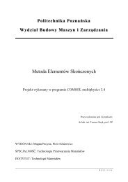
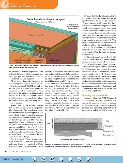
Figure 2. A complex geometry and the use of very specialized materials make the optimization of ultrasonic<br />
probes a challenging modeling task.<br />
not consider the acoustic properties of their<br />
probes at the level of detail we require. You<br />
could even say that we know more about<br />
the materials than the suppliers.<br />
With a simulation model, however, we<br />
can investigate changes in both the materials<br />
and operation. <strong>COMSOL</strong> Multiphysics<br />
has made this easy with dedicated<br />
structural-acoustics interactions as well<br />
as allowing the inclusion of other coupled<br />
physics. Best of all, a <strong>COMSOL</strong> model<br />
provides results in one month that otherwise<br />
would take a year and many prototypes<br />
to achieve.<br />
Among the things we are examining is<br />
how the mechanical layers in the probes<br />
affect bandwidth. We can change many<br />
aspects of the manufacturing process and<br />
easily check if the geometrical aspects,<br />
such as the thickness of the ceramic layer,<br />
are best for our purposes. Moreover, the<br />
model allows the simulation of important<br />
properties such as directivity and beamsteering<br />
capabilities. Once we found a<br />
way to optimize these properties, we then<br />
ask the manufacturer to modify its product<br />
accordingly or change some of the features<br />
of our probe design.<br />
Our first model (Figure 3) gave us a<br />
clear picture of the material properties<br />
and made it easy to recognize the effects<br />
of each on transducer performance. It included<br />
a study of the piezoelectric material<br />
and critical elements to be considered<br />
in the transducer manufacturing stages,<br />
by simulating the electric impedance and<br />
far field pressure level (Figure 4).<br />
The simulations also included a matching<br />
layer in front of the disk. This layer<br />
is important because, just as with an<br />
electric system where impedances must<br />
match to transfer maximum power, the<br />
same is true for transferring acoustic<br />
power from the piezo-disk to the human<br />
body. This acoustic impedance is measured<br />
in Mrayls. In this case, the ceramic<br />
material has a high acoustic impedance<br />
(30 Mrayls), while the biological material<br />
has a low value (1.5 Mrayls).<br />
We found that the elasticity, piezoelectric<br />
and dielectric material properties were all<br />
equally critical in determining the behavior<br />
of the transducer, which meant that these<br />
parameters could not be simplified in a full<br />
model of the complete probe. Agreement<br />
between test measurements and simulation<br />
results were good over the entire frequency<br />
range, where the resonance and antiresonance<br />
frequencies fit each other within an<br />
error margin of approximately 3%. This<br />
gave us confidence in the techniques we<br />
used to model this type of application.<br />
Further, by investigating the backing<br />
substrate, we also found that its parameters<br />
greatly affect the electrical impedance<br />
response.<br />
In this first model, we used perfectly<br />
matched layers (PML) to reduce computational<br />
time and memory. For our transducers,<br />
it was important to study pressure<br />
in the far field region, and the simulated<br />
far field pressure was compared to measurements<br />
using a membrane hydrophone<br />
placed at 30 cm depth in a water<br />
tank. Biological tissue has acoustic properties<br />
very similar to water, which is often<br />
used as the standard for testing purposes.<br />
We found discrepancies of less than 5% at<br />
the maximum amplitude frequencies and<br />
differences of less than 1 dB for the corresponding<br />
amplitudes.<br />
Modeling the Entire Probe<br />
Having seen how well <strong>COMSOL</strong> worked<br />
for simulating the probe materials, our<br />
next model expanded the scope to include<br />
an actual probe with its very complicated<br />
geometry and operating configuration. It<br />
simulated a wideband 5-MHz linear ar-<br />
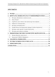
Figure 3. Model used to simulate the final far field pressure as well as the transducer’s directivity performance<br />
when the substrate and front matching layer were included.<br />
1 6 // <strong>COMSOL</strong> NEWS 2 0 1 2<br />
<strong>COMSOL</strong> <strong>News</strong> 2012-17.indd 16<br />
➮<br />
Cov ToC + – A<br />
➭<br />
5/15/12 2:59 PM