COMSOL News
COMSOL News
COMSOL News

Create successful ePaper yourself
Turn your PDF publications into a flip-book with our unique Google optimized e-Paper software.
MULTIPHYSICS<br />
TOYOTA RESEARCH INSTITUTE OF NORTH AMERICA, ANN ARBOR, MI<br />
Hot Under the Hood<br />
Toyota hybrid vehicles have sophisticated<br />
electrical systems in which many<br />
power diodes and power semiconductors<br />
such as insulated gate bipolar transistors<br />
(IGBTs) are used for power conversion<br />
and other applications. These components<br />
are standard planar silicon devices<br />
measuring a few centimeters per side,<br />
with high power dissipation.<br />
In these hybrid vehicles, they are<br />
mounted on aluminum heat sinks, or<br />
cold plates, through which a water/glycol<br />
coolant mixture is pumped. In earlier<br />
model years, the cold plate design<br />
featured a fluid inlet on one side of the<br />
plate, outlet on the other side, and in<br />
between were arrangements of mostly<br />
straight cooling channels through which<br />
the coolant flowed. The long channels<br />
provided adequate heat transfer but it<br />
came at the cost of a significant pressure<br />
drop across the plate.<br />
However, the technology roadmap for<br />
these power components calls for them<br />
to shrink to about half their current<br />
size while dissipating the same amount<br />
of power, meaning that heat fluxes will<br />
have to increase. In addition, although<br />
they have a 150 °C maximum operating<br />
temperature, typical silicon devices are<br />
kept at lower temperatures for greater<br />
component reliability. Moreover, the role<br />
“ Toyota decided to look at<br />
re-engineering the cold<br />
plate with an eye toward<br />
achieving optimum heat<br />
transfer and negligible<br />
additional pressure drop<br />
simultaneously.”<br />
of such devices is becoming more important<br />
as the electrification of vehicle systems<br />
increases.<br />
All of these factors mean that thermal<br />
management of these devices will become<br />
more difficult than it has been to date.<br />
It might seem reasonable to simply redesign<br />
the cold plates so that more coolant<br />
can be pumped through them. But<br />
that would require more pumping power,<br />
and with space already at a premium in<br />
the engine compartment where the pump<br />
is located, moving to a larger, more powerful<br />
pump or adding an additional pump<br />
is unacceptable.<br />
Instead, Toyota decided to look at reengineering<br />
the cold plate with an eye<br />
toward achieving optimum heat transfer<br />
and negligible additional pressure<br />
drop simultaneously. If both could be<br />
achieved, thermal objectives could be<br />
met at no significant increase in system<br />
pumping capacity.<br />
Jet Impingement an<br />
Incomplete Solution<br />
“Many researchers working on diverse<br />
applications have identified jet<br />
impingement as an attractive way to<br />
cool surfaces,” said Dede. “But while jet<br />
impingement performs well with respect<br />
heat dissipation close to the jet, it’s less<br />
than optimum as you move away from<br />
the orifice.”<br />
The reason is that the highest heat<br />
transfer occurs close to the jet entrance<br />
where the fluid is the coolest and velocity<br />
is the highest. As a result, much<br />
heat-transfer capability is lost by the<br />
time the coolant reaches the exit of the<br />
cold plate.<br />
One solution to this problem is to combine<br />
jet impingement with a peripheral<br />
channel structure to increase the areaaverage<br />
heat transfer. “It’s in your interest<br />
to make those channels short to keep<br />
pressure drop to a minimum, but short,<br />
straight channels aren’t efficient enough<br />
for our use,” Dede explained. “Our goal<br />
was to come up with a combination<br />
jet-impingement/channel-flow-based cold<br />
plate with optimally designed branching<br />
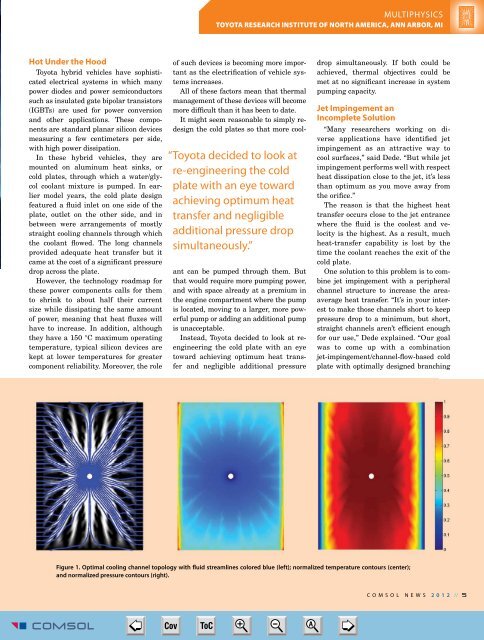
Figure 1. Optimal cooling channel topology with fluid streamlines colored blue (left); normalized temperature contours (center);<br />
and normalized pressure contours (right).<br />
<strong>COMSOL</strong> NEWS 2 0 1 2 // 5<br />
<strong>COMSOL</strong> <strong>News</strong> 2012-17.indd 5<br />
➮<br />
Cov ToC + – A<br />
➭<br />
5/15/12 2:59 PM