ACS5000-E/W Installation Manual - Brivo Systems
ACS5000-E/W Installation Manual - Brivo Systems
ACS5000-E/W Installation Manual - Brivo Systems

You also want an ePaper? Increase the reach of your titles
YUMPU automatically turns print PDFs into web optimized ePapers that Google loves.
Page 16<br />
<strong>Installation</strong> <strong>Manual</strong><br />
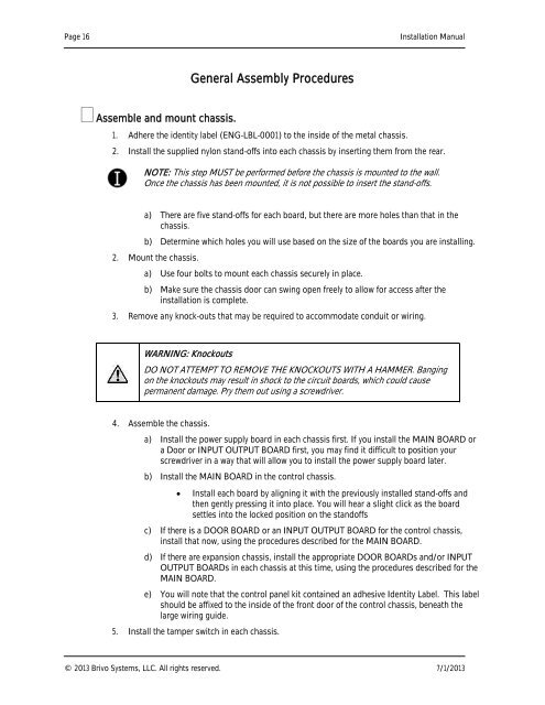
General Assembly Procedures<br />
Assemble and mount chassis.<br />
1. Adhere the identity label (ENG-LBL-0001) to the inside of the metal chassis.<br />
2. Install the supplied nylon stand-offs into each chassis by inserting them from the rear.<br />
NOTE: This step MUST be performed before the chassis is mounted to the wall.<br />
Once the chassis has been mounted, it is not possible to insert the stand-offs.<br />
a) There are five stand-offs for each board, but there are more holes than that in the<br />
chassis.<br />
b) Determine which holes you will use based on the size of the boards you are installing.<br />
2. Mount the chassis.<br />
a) Use four bolts to mount each chassis securely in place.<br />
b) Make sure the chassis door can swing open freely to allow for access after the<br />
installation is complete.<br />
3. Remove any knock-outs that may be required to accommodate conduit or wiring.<br />
WARNING: Knockouts<br />
DO NOT ATTEMPT TO REMOVE THE KNOCKOUTS WITH A HAMMER. Banging<br />
on the knockouts may result in shock to the circuit boards, which could cause<br />
permanent damage. Pry them out using a screwdriver.<br />
4. Assemble the chassis.<br />
a) Install the power supply board in each chassis first. If you install the MAIN BOARD or<br />
a Door or INPUT OUTPUT BOARD first, you may find it difficult to position your<br />
screwdriver in a way that will allow you to install the power supply board later.<br />
b) Install the MAIN BOARD in the control chassis.<br />
<br />
Install each board by aligning it with the previously installed stand-offs and<br />
then gently pressing it into place. You will hear a slight click as the board<br />
settles into the locked position on the standoffs<br />
c) If there is a DOOR BOARD or an INPUT OUTPUT BOARD for the control chassis,<br />
install that now, using the procedures described for the MAIN BOARD.<br />
d) If there are expansion chassis, install the appropriate DOOR BOARDs and/or INPUT<br />
OUTPUT BOARDs in each chassis at this time, using the procedures described for the<br />
MAIN BOARD.<br />
e) You will note that the control panel kit contained an adhesive Identity Label. This label<br />
should be affixed to the inside of the front door of the control chassis, beneath the<br />
large wiring guide.<br />
5. Install the tamper switch in each chassis.<br />
© 2013 <strong>Brivo</strong> <strong>Systems</strong>, LLC. All rights reserved. 7/1/2013