ACS5000-E/W Installation Manual - Brivo Systems
ACS5000-E/W Installation Manual - Brivo Systems
ACS5000-E/W Installation Manual - Brivo Systems

You also want an ePaper? Increase the reach of your titles
YUMPU automatically turns print PDFs into web optimized ePapers that Google loves.
Page 18<br />
<strong>Installation</strong> <strong>Manual</strong><br />
WARNING: Powering Electronic Strikes and Latches<br />
DO NOT POWER ELECTRONIC STRIKES AND LATCHES WITH THE BATTERY (OR<br />
OTHER POWER SOURCE) USED TO POWER THE CONTROL PANEL; DOING SO<br />
WILL CAUSE DAMAGE TO THE BRIVO CONTROL PANEL. USE ONLY A UL<br />
LISTED BURGLAR ALARM OR ACCESS CONTROL SYSTEM TO POWER<br />
ELECTRONIC STRIKES AND LATCHES.<br />
Connect the AC Power Indicator LED for each chassis to the power supply for that<br />
chassis.<br />
1. Mount the AC power indicated LED on the front door of the chassis by pushing it through the<br />
hold in the upper left corner of the door and securing using the bolt and washer included with<br />
your packaging.<br />
2. Connect the white and green wires from the AC power indicated LED to the 16.5 VAC terminals<br />
of the power supply board.<br />
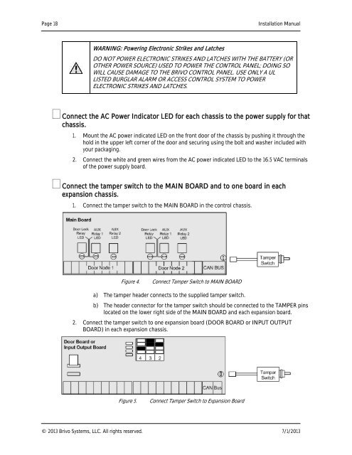
Connect the tamper switch to the MAIN BOARD and to one board in each<br />
expansion chassis.<br />
1. Connect the tamper switch to the MAIN BOARD in the control chassis.<br />
Figure 4.<br />
Connect Tamper Switch to MAIN BOARD<br />
a) The tamper header connects to the supplied tamper switch.<br />
b) The header connector for the tamper switch should be connected to the TAMPER pins<br />
located on the lower right side of the MAIN BOARD and each expansion board.<br />
2. Connect the tamper switch to one expansion board (DOOR BOARD or INPUT OUTPUT<br />
BOARD) in each expansion chassis.<br />
Figure 5.<br />
Connect Tamper Switch to Expansion Board<br />
© 2013 <strong>Brivo</strong> <strong>Systems</strong>, LLC. All rights reserved. 7/1/2013