Service Manual - Haldex
Service Manual - Haldex
Service Manual - Haldex

You also want an ePaper? Increase the reach of your titles
YUMPU automatically turns print PDFs into web optimized ePapers that Google loves.
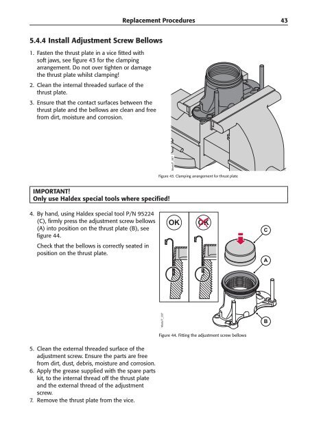
5.4.4 Install Adjustment Screw Bellows<br />
1. Fasten the thrust plate in a vice fitted with<br />
soft jaws, see figure 43 for the clamping<br />
arrangement. Do not over tighten or damage<br />
the thrust plate whilst clamping!<br />
2. Clean the internal threaded surface of the<br />
thrust plate.<br />
3. Ensure that the contact surfaces between the<br />
thrust plate and the bellows are clean and free<br />
from dirt, moisture and corrosion.<br />
IMPORTANT!<br />
Only use <strong>Haldex</strong> special tools where specifi ed!<br />
4. By hand, using <strong>Haldex</strong> special tool P/N 95224<br />
(C), firmly press the adjustment screw bellows<br />
(A) into position on the thrust plate (B), see<br />
figure 44.<br />
Check that the bellows is correctly seated in<br />
position on the thrust plate.<br />
5. Clean the external threaded surface of the<br />
adjustment screw. Ensure the parts are free<br />
from dirt, dust, debris, moisture and corrosion.<br />
6. Apply the grease supplied with the spare parts<br />
kit, to the internal thread off the thrust plate<br />
and the external thread of the adjustment<br />
screw.<br />
7. Remove the thrust plate from the vice.<br />
Replacement Procedures<br />
ModulT_067<br />
Figure 43. Clamping arrangement for thrust plate<br />
ModulT_037<br />
OK<br />
OK<br />
Figure 44. Fitting the adjustment screw bellows<br />
C<br />
A<br />
B<br />
43