Service Manual - Haldex
Service Manual - Haldex
Service Manual - Haldex

You also want an ePaper? Increase the reach of your titles
YUMPU automatically turns print PDFs into web optimized ePapers that Google loves.
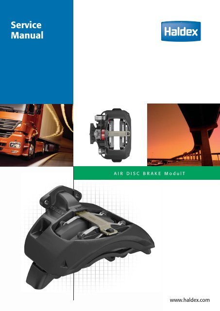
<strong>Service</strong><br />
<strong>Manual</strong><br />
AIR DISC BRAKE ModulT<br />
www.haldex.com
Table of Contents<br />
Disclaimer 2<br />
1 Introduction 3<br />
1.1 General Information .....................................................................................................................3<br />
1.2 The <strong>Haldex</strong> ModulT .......................................................................................................................4<br />
1.3 Functional Description .................................................................................................................5<br />
2 Safety Precautions 6<br />
2.1 General Information .....................................................................................................................6<br />
2.2 Installation ......................................................................................................................................6<br />
2.3 Adjustment of Control System/Valves .....................................................................................7<br />
2.4 Brake Chamber ..............................................................................................................................8<br />
2.5 Recycling .........................................................................................................................................8<br />
2.5 Cleaning ...........................................................................................................................................8<br />
2.6 Surface fi nishing for Disc Brake ................................................................................................9<br />
3 Initial and Final Procedures 10<br />
3.1 General Information .................................................................................................................. 10<br />
3.2 Initial Procedure ......................................................................................................................... 10<br />
3.3 Function Test ............................................................................................................................... 12<br />
3.4 Final Procedure ........................................................................................................................... 14<br />
4 Inspection Procedures 16<br />
4.1 General Information .................................................................................................................. 16<br />
4.2 Inspection intervals ................................................................................................................... 16<br />
4.3 Inspections .................................................................................................................................. 17<br />
5 Replacement Procedures 30<br />
5.1 General Information .................................................................................................................. 30<br />
5.2 Replacement of Brake Pads .................................................................................................... 30<br />
5.3 Replacement of Brake Chamber............................................................................................. 36<br />
5.4 Replacement of Adjustment Screw Bellows ....................................................................... 41<br />
5.5 Replacement of Slide Function Assembly ........................................................................... 46<br />
5.6 Replacement of Reset Shaft Complete ................................................................................. 57<br />
5.7 Replacement of Disc Brake .................................................................................................... 59<br />
6 Specifi cations 61<br />
6.1 Wear Limits .................................................................................................................................. 61<br />
6.2 Tightening Torques ..................................................................................................................... 61<br />
7 Tools 62<br />
7.1 <strong>Haldex</strong> ModulT Tool Kit complete ......................................................................................... 62<br />
7.2 Special tools for <strong>Haldex</strong> ModulT. ...........................................................................................63<br />
8 Fault Finding 64<br />
9 Component List and Exploded view 66<br />
9.1 Component List .......................................................................................................................... 66<br />
9.2 Exploded view ............................................................................................................................. 67<br />
1
2<br />
Please note<br />
Disclaimer<br />
This <strong>Service</strong> <strong>Manual</strong> is intended for the exclusive use by trained persons within the commercial<br />
vehicle industry and related workshops.<br />
The content of this manual is not all-inclusive and not legally binding and <strong>Haldex</strong> Brake Products<br />
AB assumes no liability as a result of its use. All information contained in the manual does neither<br />
represent ensured characteristics of the product nor represent a guarantee. <strong>Haldex</strong> Brake Products<br />
AB reserves the right to make changes in the interest of technical progress without prior notice.<br />
No liability is assumed as a result of incorrect or inappropriate parts being fi tted to the product or<br />
the omittance of appropriate tests after the servicing of the product. Use appropriate spare parts’<br />
documentation when obtaining spare parts. Use only genuine <strong>Haldex</strong> spare parts in repairs.<br />
This manual is subject to a copyright of <strong>Haldex</strong> Brake Products AB that reserves all rights. No part<br />
of this manual may be reproduced, copied or translated in any form or by any means without the<br />
prior written permission of <strong>Haldex</strong> Brake Products AB. Brand names mentioned in this manual are<br />
not identifi ed as such in all cases, but they nevertheless are subject to the provisions of trademark<br />
legislation.<br />
In case of confl icting language versions of this manual, the English original prevails.<br />
The failure of any individual provision of this disclaimer to comply with current legal provisions does<br />
not affect the validity of the remaining provisions.
1 Introduction<br />
1.1 General Information<br />
Introduction<br />
This <strong>Haldex</strong> ModulT <strong>Service</strong> <strong>Manual</strong> is divided up into chapters, these chapters are sequenced in the<br />
same way that a user should read and follow the manual.<br />
Chapter “1. Introduction” provides a general overview of this service manual and the ModulT disc<br />
brake.<br />
It is important to carefully read chapter ”2. Safety Precautions” before starting any workshop<br />
procedures. This is to inform the user about the safety measures and the potentially hazardous<br />
situations which, if not avoided, could result in serious injury or death!<br />
Chapter “3. Initial and Final Procedures” describes the start and fi nish activities necessary to be able<br />
to carry out inspection and replacement work. It also describes the function test for the ModulT disc<br />
brake.<br />
Consult chapter ”4. Inspection Procedures” for information and instruction on inspecting the ModulT<br />
disc brake. Chapter “4.2. Inspection Intervals” is useful for the recommended disc brakes inspection<br />
intervals. Here the Inspection Intervals table displays how frequent the different brake components<br />
shall be inspected and on which pages the check instructions are to be found.<br />
If any inspection shows that a replacement activity needs to be performed, continue to the<br />
appropriate section in chapter ”5. Replacement Procedures”.<br />
Chapter “6. Specifi cations” contains technical data for the ModulT disc brake.<br />
Chapter “7. Tools” contains information about the <strong>Haldex</strong> ModulT Tool Kit, which is essential for<br />
carrying out much of the replacement procedure work described in this manual.<br />
Chapter ”8. Fault Finding” should be used to help with the self diagnosis of any problem being<br />
experienced.<br />
Finally Chapter “9. Components List” lists and shows what spare part components are available for<br />
the ModulT disc brake.<br />
1.1.1 Spare Parts<br />
It is vital that only <strong>Haldex</strong> original spare parts are used during all service replacement activities.<br />
The use of none <strong>Haldex</strong> original spare parts can affect the function, performance and/or lifetime of<br />
the parts.<br />
The use of none <strong>Haldex</strong> original spare parts will immediately terminate any warranty of the disc<br />
brake unit.<br />
3
4 Introduction<br />
1.2 The <strong>Haldex</strong> ModulT<br />
The <strong>Haldex</strong> ModulT is an air disc brake platform<br />
developed for the purpose of meeting increased<br />
customer demands on performance, robustness,<br />
service up-time and weight.<br />
The ModulT superior design encompasses the<br />
following advantages:<br />
� Low weight;<br />
� Single tappet mechanism with similar<br />
clamping force distribution as <strong>Haldex</strong> twin<br />
tappet mechanism;<br />
� Simplifi ed maintenance; boltless pad retainer<br />
and only two bolts in the complete brake;<br />
� Modular; the same mechanism and sliding<br />
function design used on multiple brake sizes;<br />
� Long service life; stainless sliding pins, PTFE<br />
coated steel bushings, and the mechanism<br />
bellows is folded inwards thus protected from<br />
external affection (stones/blister etc.);<br />
� High effi ciency; the use of double roller<br />
bearings for the mechanism lever keeps the<br />
hysteresis low and thus a high effi ciency is<br />
achieved.<br />
ModulT_053<br />
Figure 1. The <strong>Haldex</strong> ModulT Disc Brake
1.3 Functional Description<br />
The ModulT is designed to provide high<br />
performance coupled with low weight, durability<br />
and a minimum number of wearing parts.<br />
The ModulT enhances a fl oating monobloc<br />
calliper (C) and an integrated adjustment unit<br />
which compensates for brake pad wear.<br />
The unit, which is actuated by the mechanism<br />
lever (A), presses the inner brake pad (B) against<br />
the disc, which then causes the calliper (C) to<br />
slide laterally, so that the outer brake pad (D)<br />
also comes in contact with the disc, see fi gure 2.<br />
The calliper moves on slide pins (E), see fi gure<br />
3. Where the disc brake also serves as a parking<br />
brake, the unit is actuated by a spring brake<br />
chamber (F).<br />
Introduction<br />
ModulT_001<br />
A<br />
Figure 2. Functional description<br />
ModulT_069<br />
Figure 3. Slide pins and spring brake chamber<br />
E<br />
E<br />
F<br />
C<br />
B<br />
D<br />
5
6 Safety Precautions<br />
2 Safety Precautions<br />
2.1 General Information<br />
This chapter comprehends the Safety Precautions that shall be read and followed before any<br />
Inspection/Removal/Installation procedure described in this <strong>Service</strong> <strong>Manual</strong> is started.<br />
This <strong>Service</strong> <strong>Manual</strong> is intended for the exclusive use of trained persons within the commercial<br />
vehicle industry and related work shops.<br />
Three different alert levels are used through out this <strong>Service</strong> <strong>Manual</strong>: Warning, Important and Note.<br />
Their differences are explained below:<br />
A Warning message is always accompanied by a safety alert symbol.<br />
The safety alert symbol is used to alert about potential personal injury<br />
hazards.<br />
To avoid hazards, obey all safety messages that follow this symbol.<br />
Failure to observe this information can cause serious personal injury or<br />
death!<br />
IMPORTANT!<br />
An important message is always accompanied by the signal word IMPORTANT!<br />
The Important sign means risk of damage to the brake! Failure to observe this<br />
information could result in damage to the whole brake or parts of it!<br />
NOTE!<br />
A notifi cation message is always accompanied by the word NOTE!<br />
The Note sign is used to emphasize important information and is not to be regarded<br />
as hazard information.<br />
2.2 Installation<br />
The disc brake must not be installed or treated in such a way that exposes it to none normal<br />
thermal, mechanical or chemical infl uences that can cause reduced braking effect or damage to vital<br />
components in the brakes. These infl uences/damages may result in a shortened service life for the<br />
disc brake and its components, reduced brake effect or at worst total brake failure.
Safety Precautions<br />
2.3 Adjustment of Control System/Valves<br />
Failure to follow the instructions in this chapter may accelerate the wear to the brake pads and may<br />
cause damage/repeated damage to the disc brake, axle and/or wheel brake components.<br />
2.3.1 Before entering the Vehicle into service<br />
Prior to fi rst time use a vehicles disc brake operating systems must be checked and adjusted (if<br />
necessary) in accordance with the relevant brake calculations. Contact the vehicle manufacturer for<br />
relevant information.<br />
2.3.2 Replacing Spare Parts<br />
Always use spare parts that are approved for the vehicle, axle or disc brake. Following replacement of<br />
any essential components or spare parts in the disc brake operating system (such as brake valves or<br />
control units), the disc brake operating system must also be checked and adjusted (if necessary) in<br />
accordance with the relevant braking calculations.<br />
2.3.3 Brake Force Distribution<br />
It is very important that the distribution of brake force, between axles/vehicles, in a vehicle<br />
combination is adapted so that the brake force for each axle/vehicle is proportioned in accordance<br />
with the legally applied braking calculations.<br />
If the brake force is not correctly distributed it can lead to excessive braking of a vehicle and/or one<br />
or more axles in the combination. This can result in overheating, accelerated wear and damage to<br />
the disc brake, pads, discs, tyres and wheel components.<br />
Before a vehicle is entered into service it must be set up according to the specifi ed values in the<br />
relevant brake calculations. After the pads/brake discs have been run in for a period of around 3,000-<br />
5,000 km the brake force distribution between the truck/tractor and trailer may require adjustment.<br />
Brake adjustment must also be carried out during repairs/changing spare parts when heating/<br />
overheating has suspected to damaged the axle/brake components (e.g. rubber components, hub/<br />
wheel bearings and brake disc).<br />
Contact the vehicle supplier for information on the appropriate action.<br />
Following replacement of any essential components or spare parts in the disc brake operating<br />
system (e.g. brake valves or control units), the disc brake operating system must also be checked and<br />
adjusted in accordance with the relevant braking calculations.<br />
Failure to follow these instructions may cause damage/repeated damage to the disc brake, axle and/<br />
or wheel brake components.<br />
7
8 Safety Precautions<br />
2.4 Brake Chamber<br />
Moisture/water ingress into the disc brake’s<br />
mechanism housing will potentially affect the<br />
function of the disc brake and as a result shorten<br />
its life.<br />
Therefore, to prevent water ingress it is important<br />
that the disc brake chamber is of the correct<br />
design and that the seal between the brake<br />
chamber and disc brake mating surface is<br />
undamaged correctly in place.<br />
It is also important for the disc brake’s function<br />
that the brake chamber housing is correctly<br />
ventilated.<br />
As a minimum, the drain holes facing downwards<br />
must be open, see fi gure 4. Other drain plugs can<br />
remain in position in the brake chamber housing.<br />
ModulT_034<br />
Figure 4. Brake chamber ventilation<br />
IMPORTANT!<br />
If all the plugs remain fi tted, the brake chamber and disc brake will not operate<br />
correctly!<br />
2.5 Recycling<br />
When replacing the disc brake or parts thereof, the components removed must be recycled/<br />
destroyed in compliance with applicable environmental legislation, regulations and provisions.<br />
2.6 Cleaning<br />
For the disc brake to function correctly it is important to ensure it is kept clean and that its normal<br />
movements are not restricted by mud, ice, snow, objects, etc. Damage may cause direct brake failure<br />
or damp/dirt penetration resulting in malfunction/shortening of the service life of the disc brake.<br />
IMPORTANT!<br />
It is important to take care when using chemicals and/or cleaning tools (e.g.<br />
knife, brush, etc). This to avoid damage or displacement of hoses, seals and other<br />
components.
Safety Precautions<br />
2.7 Surface fi nishing for Disc Brake<br />
2.7.1 Painting<br />
The disc brake can be fi nished with paint that has trade approval for this purpose (automotive<br />
paint). Care must be taken to ensure that the paint layer does not cause damage and/or restrict the<br />
natural movement or operation of the disc brake. All contact surfaces, friction and rubber parts must<br />
therefore be protected or masked.<br />
The following areas must not be painted:<br />
All bellows, Reset Shaft and it’s protection Plug, complete Brake Pads, the swept area of the disc, the<br />
disc brake mounting surfaces to axle/brake chamber and all bolted connections.<br />
2.7.2 Shot-blasting<br />
IMPORTANT!<br />
Failure to follow the instructions below could compromise safety and/or reduce the<br />
life of the disc brake and its components.<br />
If the vehicle is shot blasted, all rubber parts and pads on the disc brake must be protected. The<br />
brake chamber must be fi tted (or any protective parts that have a similar sealing function). The<br />
shipping seal fi tted to the brake chamber opening on a new disc brake does not provide adequate<br />
protection during shot-blasting.<br />
NOTE!<br />
Do not forget to follow the recommendations of the brake chamber manufacturer.<br />
The disc brake must be thoroughly cleaned after blasting to ensure that its natural movement is not<br />
obstructed by remnants of shot-blasting material. Check seals and rubber parts to make sure they<br />
have not been damaged. Also refer to the axle manufacturer’s instructions.<br />
9
10 Initial and Final Procedures<br />
3 Initial and Final Procedures<br />
3.1 General Information<br />
The objective of this chapter is to give guidelines on how Initial and Final Procedures shall be<br />
performed in a standardised way.<br />
Initial Procedure is a recurring procedure that have to be performed prior to the Inspection and/or<br />
Replacement procedures covered in this <strong>Service</strong> <strong>Manual</strong>.<br />
Final Procedure is a recurring procedure that have to be performed after an Inspection and/or<br />
Replacement procedure covered in this <strong>Service</strong> <strong>Manual</strong>.<br />
3.2 Initial Procedure<br />
3.2.1 Lift up and support the vehicle axle<br />
At least one of the vehicle´s axles shall be chocked to prevent<br />
involuntary movement of the vehicle!<br />
The vehicle manufacturer´s safety precautions shall be followed when<br />
working on the vehicle!<br />
Local safety precautions shall be complied!<br />
1. On a flat and even surface, block the wheels,<br />
see figure 5.<br />
2. Lift the axles and place on stands.<br />
ModulT_004<br />
Figure 5. Block the wheels
3. Release the parking brake.<br />
Initial and Final Procedures<br />
If the disc brake is equipped with a parking brake function, ensure that<br />
the brake system is depressurised, that the spring brake chamber is fully<br />
disengaged and mechanically secured in the released position.<br />
See the vehicle manufacturer’s instructions.<br />
3.2.2 Removing the wheel<br />
ModulT_055<br />
Figure 6. Mechanically secure in the released position<br />
Take all necessary safety precautions before wheel removal!<br />
The vehicle manufacturer´s safety precautions shall also be followed!<br />
1. Check the free rolling resistance, if the<br />
resistance is higher than expected, tap the<br />
tyre to remove any normal rest tension. If the<br />
wheel still does not rotate freely then consult<br />
chapter ”8. Fault Finding” to assist further.<br />
2. Remove the wheel nuts followed by the<br />
wheel, see figure 7.<br />
ModulT_005<br />
Figure 7. Remove the wheel<br />
11
12 Initial and Final Procedures<br />
3.3 Function Test<br />
3.3.1 Check of Adjustment Unit<br />
The function test can be carried out with the<br />
wheel both fi tted or removed.<br />
1. Check that the wheel/hub can rotate freely.<br />
If it does not then first tap to remove any rest<br />
tension. If the wheel still does not rotate freely<br />
then consult chapter ”8. Fault Finding” to<br />
assist further.<br />
2. Remove the reset shaft protection plug (A),<br />
see figure 8.<br />
IMPORTANT!<br />
Use recommended tools only!<br />
NOTE!<br />
The Torx 55 and the Thrust plate must be allowed to move unhindered!<br />
IMPORTANT!<br />
Never use an impact wrench or similar to turn the reset shaft. This may damage<br />
internal parts of the mechanism! Torque is 20 Nm max.<br />
3. Using <strong>Haldex</strong> special tool P/N95232 (Torx 55),<br />
de-adjust the brake by turning the reset shaft<br />
anti-clockwise by 4 clicks, or till the end stop,<br />
see (B) figure 8. A distinct clicking sound shall<br />
be heard and felt when de-adjusting.<br />
ModulT_006<br />
Figure 8. De-adjustment via the reset shaft<br />
A<br />
B<br />
4<br />
3<br />
2<br />
1
Initial and Final Procedures<br />
IMPORTANT!<br />
When reaching the end stop position of de-adjustment, never tighten and<br />
leave. Leaving the reset shaft tightened in the de-adjust position could stop the<br />
adjustment function from working!<br />
After reaching the end stop position always then adjust by turning the reset shaft<br />
clockwise 90 degrees, thus activating the adjustment function.<br />
4. Leave the Torx 55 in position in the reset shaft.<br />
5. Actuate the brakes 5 times by pressing and<br />
releasing the vehicles brake pedal through its<br />
full stroke. See figure 9. If no brake chamber<br />
is fitted then actuate the brake chamber lever<br />
manually with a suitable tool.<br />
6. The Torx 55 must rotate clockwise only on<br />
each actuation, showing that the automatic<br />
adjustment function is working.<br />
7. If the Torx 55 rotates back and forth or not<br />
at all, then the adjustment function is not<br />
working correctly.<br />
8. To check further, manually adjust the reset<br />
shaft by turning the Torx 55 clockwise by<br />
360 degrees, and then anti-clockwise by 180<br />
degrees to ensure the adjuster is not jammed<br />
at the full de-adjust position.<br />
9. Also note that once the excessive clearance<br />
is taken up by the adjuster the Torx 55 will<br />
naturally stop rotating. If in doubt, turn the<br />
Torx 55 anti-clockwise by 180 degrees and<br />
then press the brake pedal again to check.<br />
10. If the Torx 55 still rotates back and forth<br />
during actuation then the adjustment function<br />
is defective and the calliper must be replaced.<br />
See chapter ”5.7 Replacement of Disc Brake”.<br />
ModulT_090<br />
Figure 9. Brake actuation<br />
5<br />
4<br />
x5<br />
3<br />
1<br />
2<br />
13
14 Initial and Final Procedures<br />
3.4 Final Procedure<br />
1. Using <strong>Haldex</strong> special tool P/N95232 (Torx 55),<br />
manually adjust the brake by turning the reset<br />
shaft clockwise until the pads touch the disc<br />
and you feel an end stop.<br />
2. Then turn the reset shaft anti-clockwise by 2<br />
clicks, see figure 9.1.<br />
This procedure is the initial brake pad setting.<br />
3. Fit the reset shaft protective plug into the<br />
calliper, ensure it is correctly orientated and<br />
pushed fully into its correct sealing position.<br />
Failure to do so may compromise the life of<br />
the brake!<br />
See Figure 10.<br />
3.4.1 Mounting of the wheel<br />
Figure 9.1. Initial brake pad setting<br />
OK<br />
OK<br />
Figure 10. Correct fitment of the protective plug<br />
2 “CLICK”<br />
Make sure that the brake hoses are in good condition, that they are<br />
layed/ducted and fastened correctly.<br />
1. Check the free rolling resistance. The disc<br />
brake must not be obstructed in any way.<br />
2. Mount the wheel, see Figure 11.<br />
ModulT_007<br />
Figure 11. Mount the wheel<br />
OK<br />
OK<br />
“CLICK”<br />
1
3.4.2 Lowering of the vehicle axle<br />
Initial and Final Procedures<br />
If the disc brake is equipped with a parking brake function, ensure that<br />
the brake system is pressurised, that the spring brake chamber is fully<br />
engaged and mechanically secured in the active position.<br />
See the vehicle manufacturer’s instructions.<br />
ModulT_003<br />
Figure 12. Mechanically secure in the active position<br />
IMPORTANT!<br />
Apply air to the parking brake. Make sure that there is suffi cient air in the system<br />
(min. 6 bar).<br />
1. Activate the parking brake if fitted with a<br />
spring brake chamber.<br />
2. Lift the axles so that the stands can be<br />
removed.<br />
3. Carefully lower the vehicle to the ground.<br />
4. Remove the wheel blocks, see Figure 13.<br />
ModulT_056<br />
Figure 13. Remove the stops<br />
IMPORTANT!<br />
After carrying out any work, always fi nish with a general checking operation<br />
followed by test drive to ensure that the brakes are working correctly!<br />
15
16 Inspection Procedures<br />
4 Inspection Procedures<br />
4.1 General Information<br />
The objective of this chapter is to give guidance on how inspection of the brake components shall be<br />
conducted. Always start by consulting the Inspection interval table below in chapter 4.2.<br />
The Inspection interval table displays how frequent the different brake components shall be<br />
inspected and on which pages the check instructions are found.<br />
The majority of the inspections demand that the wheel is removed from the vehicle. Before removing<br />
the wheel read chapter ”2. Safety Precautions” followed by ”3. Initial and Final Procedures”.<br />
4.2 Inspection intervals<br />
The check intervals specifi ed in the table below are maximum intervals. Depending on the vehicle<br />
application, type of driving, adjustment to the vehicle manufacturer’s service/inspection intervals etc,<br />
there may be a need for more frequent inspections.<br />
C = Check<br />
A = Inspection<br />
* = With wheels fi tted<br />
** = With wheels removed<br />
Before starting to use vehicle<br />
Daily<br />
After 3000-5000 km.<br />
Every 3 month<br />
Every 12 month<br />
If parts are replaced in operating<br />
system.<br />
Adjustment of Control System/Valves C/A* C* C/A* 7<br />
Braking Force Distribution - Tractor/Trailer C/A* C* C/A* 7<br />
Function Test C* C** 12<br />
Safety Check C* C** 17<br />
Brake Pads I* I** 18<br />
Brake Disc I* I** 20<br />
Plugs and Protective Cups I** 21<br />
Thrust Plate Guide Pins I** 22<br />
Actuation Interface I** 23<br />
Slide Pin Bellows I** 26<br />
Adjustment Screw Bellows I** 27<br />
Slide Function I** 29<br />
See<br />
Page
4.3 Inspections<br />
4.3.1 Daily Safety Check<br />
Inspection Procedures<br />
Contact the <strong>Service</strong> Workshop immediately if there is any sign of reduced<br />
performance or the brakes do not work properly!<br />
1. Check that the brakes function properly before<br />
driving and that they work effectively and<br />
smoothly.<br />
2. Check that the service and parking brake<br />
function is effective by trying to drive the<br />
vehicle with the service and parking brake<br />
applied.<br />
4.3.2 Check overall condition<br />
1. Make sure you have good lighting conditions.<br />
2. Inspect visible parts of the brake and its<br />
components. Look for:<br />
- Damage<br />
- Collection of debris<br />
- Corrosion<br />
- Overheating signs<br />
- Cracks in brake discs<br />
- Unusual wear etc<br />
17
18 Inspection Procedures<br />
4.3.3 Check Brake Pad wear<br />
Wear respiratory protection in order to avoid inhaling particles which can<br />
be hazardous to your health! Brake pad wear produce dust which can<br />
cause lung damage!<br />
NOTE!<br />
Step 1 in this procedure only indicate the pad wear of the outer pad! For a full<br />
examination do all steps.<br />
1. Inspect the position of the Visual Wear<br />
Indicator (VWI), as located and shown in<br />
figure 14. This check can be done with either<br />
the wheel fitted or removed.<br />
The VWI provides an indication of pad wear<br />
condition, it does not provide an accurate<br />
measurement of pad wear on both pads.<br />
To obtain and accurate wear measurement<br />
of both pads continue with the instructions<br />
which follow.<br />
2. Remove the wheel following chapter ”3.2<br />
Initial Procedure”.<br />
3. Remove brake pads according to chapter<br />
”5.2.2 Remove Brake Pads”.<br />
4. Look for unusual conditions like excessive<br />
corrosion and high heat cycles i.e.<br />
delamination, discolouration, etc. If found<br />
refer to chapter ”8 Fault Finding” for actions.<br />
5. On both brake pads measure the distance<br />
from back plate (A) to wear surface (B) of<br />
the brake pad in four places, see figure 15.<br />
Minimum permitted lining thickness (friction<br />
material) is 2 mm.<br />
6. Check the condition of the back plate (A).<br />
7. Replace brake pads if they are worn out or<br />
if they are expected to be so before the next<br />
inspection.<br />
For replacement follow the instructions in<br />
chapter ”5.2 Replacement of Brake Pads”.<br />
8. If the inspection is completed satisfactorily,<br />
conclude by following chapters “5.2.3 Install<br />
Brake Pads” and “5.2.4 Final Procedure”.<br />
ModulT_009<br />
Figure 14. Inspection of the Visual Wear Indicator<br />
ModulT_010<br />
A<br />
>2mm<br />
Figure 15. Measuring the pad wear condition<br />
A<br />
B<br />
OK OK<br />
NOTE!<br />
This brake disc inspection check procedure is only a general guide, refer to the<br />
vehicle manufacturers documentation for specifi c brake disc information and<br />
instruction.<br />
B
4.3.4 General Brake Pad clearance check<br />
Wear respiratory protection in order to avoid inhaling particles which can<br />
be hazardous to your health! Brake pad wear produce dust which can<br />
cause lung damage!<br />
Checking the clearance is only required for an<br />
approximation of the clearance between the<br />
brake disc and the brake pads.<br />
The check can be carried out with or without the<br />
brake chamber fi tted.<br />
This check is best performed after the wheel is<br />
removed and before the brake is de-adjusted.<br />
For this situation the steps 2 and 3 below can be<br />
skipped.<br />
1. Read and follow chapters “3.2 Initial<br />
Procedure” and paragraph 4 from “5.2.2<br />
Remove Brake Pads” prior to checking the pad<br />
clearance.<br />
2. Adjust the reset shaft by inserting and<br />
manually turning the <strong>Haldex</strong> special tool P/N<br />
95232 (Torx 55) clockwise until it comes to a<br />
stop and any excessive clearance is removed.<br />
Then de-adjust the reset shaft by turning it<br />
anti-clockwise by 2 clicks.<br />
3. Activate the brake until the Torx 55 male<br />
no longer rotates because any excessive<br />
clearance has been removed by the<br />
adjustment function.<br />
4. Insert two feeler gauges in between the<br />
calliper and the outer brake pad to measure<br />
the clearance. Position the feeler gauges in the<br />
upper and lower part of the brake pad back<br />
plate so an average clearance is measured,<br />
see fi gure 16.<br />
5. The normal running clearance is between<br />
0,7mm and 1,1mm. If the measurement is<br />
outside of the normal running condition then<br />
refer to chapter ”8. Fault Finding” for further<br />
investigations.<br />
6. Once the inspection is completed satisfactorily,<br />
conclude by reading and following chapters,<br />
paragraph 6 from “5.2.3 Install Brake Pads”<br />
and all from “5.2.4 Final Procedure”.<br />
Inspection Procedures<br />
ModulT_026<br />
Figure 16. Correct location of the feeler gauges<br />
19
20 Inspection Procedures<br />
4.3.5 Check Brake Disc<br />
Wear respiratory protection in order to avoid inhaling particles which can<br />
be hazardous to your health! Brake pad wear produce dust which can<br />
cause lung damage!<br />
1. Look for wear, damages and cracks, see figure<br />
17. Also refer to the axle/vehicle manufacturer<br />
instructions.<br />
Cracks that enter the cooling ducts via the<br />
outer radius are not permitted!<br />
2. Measure the thickness of the brake disc using<br />
a slide calliper. If the brake disc has a wear<br />
ridge, the measurement can be performed<br />
using two spacers (B) (e.g. 5 mm thick flat<br />
washers), see figure 18. Reduce the measured<br />
dimension by the total thickness of the two<br />
spacers (B).<br />
Minimum thickness of the brake disc is 37<br />
mm.<br />
The brake disc must be replaced if the wear<br />
limits have been exceeded.<br />
Acceptable<br />
crack length<br />
< 75% of brake<br />
disc width<br />
ModulT_011<br />
Figure 17. Inspection of the Brake Disc<br />
ModulT_012<br />
Figure 18. Measuring the Brake Disc thickness<br />
Unacceptable<br />
crack length<br />
> 75% of brake<br />
disc width<br />
OK OK<br />
NOTE!<br />
This brake disc inspection check procedure is only a general guide, refer to the<br />
vehicle manufacturers documentation for specifi c brake disc information and<br />
instruction.<br />
B<br />
B
4.3.6 Check Plugs and Protective Cups<br />
Wear respiratory protection in order to avoid inhaling particles which can<br />
be hazardous to your health! Brake pad wear produce dust which can<br />
cause lung damage!<br />
IMPORTANT!<br />
Use a vacuum cleaner to clean surfaces. Do not use compressed air!<br />
IMPORTANT!<br />
Failure to follow the instructions below could compromise safety and/or reduce the<br />
life of the Disc Brake and its components.<br />
1. Read and follow chapter “3.2 Initial<br />
Procedure” prior to inspecting the protective<br />
plugs and cups.<br />
2. Remove dirt from surfaces if necessary.<br />
3. Check for signs of excessive heat exposure,<br />
discolouration, debris etc.<br />
4. The following plugs and protective cups shall<br />
be in place and intact:<br />
The reset shaft protection plug identified as<br />
(A) and calliper seal (B), see figure 19.<br />
Protection plug B is never removed.<br />
5. The three protection cups; two for slide pin<br />
protection (C) and one for the mechanism<br />
(D), see fi gure 20.<br />
Proctection cup D is never removed.<br />
6. Once the inspection is completed satisfactorily,<br />
conclude by reading and following chapter<br />
“3.4 Final Procedure”.<br />
Inspection Procedures<br />
ModulT_013<br />
Figure 19. The two protection plugs<br />
ModulT_014<br />
Figure 20. The three protection cups<br />
IMPORTANT!<br />
Never remove the protection plug (B) and protection cup (D) on fi gures 20 and 21. If<br />
the protection plug (B) is removed it will void warranty and will compromise the life<br />
of the disc brake!<br />
B<br />
C<br />
A<br />
C<br />
D<br />
21
22 Inspection Procedures<br />
4.3.7 Check Thrust Plate Guide Pins<br />
Wear respiratory protection in order to avoid inhaling particles which can<br />
be hazardous to your health! Brake pad wear produce dust which can<br />
cause lung damage!<br />
IMPORTANT!<br />
Use a vacuum cleaner to clean surfaces. Do not use compressed air!<br />
1. Read and follow chapter “3.2 Initial<br />
Procedure” prior to inspecting the thrust plate<br />
guide pins.<br />
2. Remove dirt from surfaces as necessary.<br />
3. Check that the two thrust plate guide pins (E),<br />
see figure 21, are in their correct position.<br />
4. Check that the thrust plate with guide pins are<br />
free to move without obstruction.<br />
5. Once the inspection is completed satisfactorily,<br />
conclude by reading and following chapter<br />
“3.4 Final Procedure”.<br />
ModulT_015<br />
Figure 21. The two thrust plate guide pins<br />
E<br />
E
4.3.8 Check Actuation Interface<br />
Inspection Procedures<br />
Wear respiratory protection in order to avoid inhaling particles which can<br />
be hazardous to your health! Brake pad wear produce dust which can<br />
cause lung damage!<br />
IMPORTANT!<br />
It is important to take care when using chemicals and/or cleaning tools (e.g.<br />
knife, brush etc). This to avoid damage or displacement of hoses, seals and other<br />
components.<br />
IMPORTANT!<br />
Use a vacuum cleaner to clean surfaces. Do not use compressed air<br />
This inspection procedure covers both types<br />
of brake chamber; normal (service) and spring<br />
brake (parking) chambers.<br />
1. Read and follow chapter “3.2 Initial<br />
Procedure” prior to inspecting the actuation<br />
interface.<br />
2. Thoroughly clean around the mating surfaces<br />
of the brake chamber (A) and calliper (B)<br />
to ensure that dirt does not get into the<br />
mechanism area when removing the brake<br />
chamber. See figure 22.<br />
ModulT_028<br />
Figure 22. The mating surfaces of the brake chamber and calliper<br />
If the disc brake is equipped with a parking brake function, ensure that<br />
the brake system is depressurised, that the spring brake chamber is fully<br />
disengaged and mechanically secured in the released position.<br />
See the vehicle manufacturer’s instructions.<br />
ModulT_055<br />
Figure 6. Mechanically secure in the released position<br />
B<br />
A<br />
23
24 Inspection Procedures<br />
Pressure from lines and components shall be released before opening<br />
them!<br />
3. If applicable ensure that the spring brake<br />
chamber (F) is fully disengaged and<br />
mechanically secured in the released<br />
position.<br />
4. Ensure that the brake chamber is<br />
depressurised.<br />
5. Remove the two nuts (E) holding the brake<br />
chamber. Remove the brake chamber (A/F)<br />
from the calliper (B), see figure 23.<br />
6. With the brake chamber removed and<br />
secured, the brake chamber actuation rod<br />
should protrude ~15 mm in its rest position,<br />
See figure 24.<br />
7. Activate the service brake, the brake chamber<br />
actuation rod should protrude ~80 mm.<br />
8. Also check that the actuation rod extends<br />
perpendicular to the external seal flange.<br />
9. Check through the aperture in the brake<br />
chamber attachment flange for moisture/<br />
corrosion, see figure 25. It’s important to<br />
look inside the aperture and not just on the<br />
surface.<br />
If corrosion is seen then further inspection<br />
is necessary. If concluded that water has<br />
ingressed causing internal corrosion/<br />
damages to the mechanism then replace<br />
the calliper complete to avoid operating<br />
problems.<br />
If action is required see chapter ”5.8<br />
Replacement of Calliper”.<br />
ModulT_091<br />
A<br />
Figure 23. Removal of brake chamber items<br />
ModulT_018<br />
Figure 24. The actuation rod<br />
ModulT_030<br />
Figure 25. The brake chamber aperture<br />
F<br />
E<br />
B
10. On the brake chamber, there must be an<br />
internal bellows (A) on the push rod, see<br />
figure 26.<br />
11. Check that the bellows are complete and not<br />
damaged by looking around and down the<br />
push rod shaft. Also look for signs of water<br />
or corrosion which may be a sign that the<br />
bellows are damaged.<br />
12. Check that the external seal flange (B)<br />
is correctly seated in place, intact and<br />
undamaged.<br />
13. Once the inspection is completed<br />
satisfactorily, conclude by reading and<br />
following chapters “5.3.3 Install Brake<br />
Chamber” and “5.3.4 Final Procedure”.<br />
Inspection Procedures<br />
ModulT_031<br />
B<br />
Figure 26. Internal view of a brake chamber<br />
A<br />
25
26 Inspection Procedures<br />
4.3.9 Check Slide Pin Bellows<br />
Wear respiratory protection in order to avoid inhaling particles which can<br />
be hazardous to your health! Brake pad wear produce dust which can<br />
cause lung damage!<br />
IMPORTANT!<br />
It is important to take care when using chemicals and/or cleaning tools (e.g.<br />
knife, brush etc). This to avoid damage or displacement of hoses, seals and other<br />
components.<br />
IMPORTANT!<br />
Use a vacuum cleaner to clean surfaces. Do not use compressed air<br />
1. Read and follow chapters “3.2 Initial<br />
Procedure” and “5.2.2 Remove Brake Pads”<br />
prior to inspecting the slide pin bellows.<br />
2. Inspect the Leading slide pin bellows (A) and<br />
the Trailing slide pin bellows (B), see figure 27.<br />
Look all around the bellows for damage signs<br />
than could have been caused by debris, stones<br />
or overheating.<br />
3. If the bellows are damaged then they need<br />
replacing. For instructions on how to replace<br />
the bellows read and follow ”5.5 Replacement<br />
of Slide Function Assembly”.<br />
4. Once the inspection is completed satisfactorily,<br />
conclude by reading and following chapters<br />
“5.2.3 Install Brake Pads” and “5.2.4 Final<br />
Procedure”.<br />
ModulT_020<br />
A<br />
B<br />
Figure 27. Inspecting the slide pin bellows
4.3.10 Check Adjustment Screw Bellows<br />
Wear respiratory protection in order to avoid inhaling particles which can<br />
be hazardous to your health! Brake pad wear produce dust which can<br />
cause lung damage!<br />
IMPORTANT!<br />
It is important to take care when using chemicals and/or cleaning tools (e.g.<br />
knife, brush etc). This to avoid damage or displacement of hoses, seals and other<br />
components.<br />
IMPORTANT!<br />
Use a vacuum cleaner to clean surfaces. Do not use compressed air!<br />
1. Read and follow chapters “3.2 Initial<br />
Procedure” and “5.2.2 Remove Brake Pads”,<br />
prior to checking the adjustment screw<br />
bellows.<br />
IMPORTANT!<br />
Never use an impact wrench or suchlike to turn the reset shaft. This may damage the<br />
disc brakes mechanism! Torque is 20 Nm max.<br />
Note!<br />
Do not over adjust/extend the thrust plate whilst carrying out the inspection. Over<br />
adjustment/extension will cause the thrust plate to disengage from the adjustment<br />
screw and if done unintentionally may cause damage to the thrust plate bellows! Max<br />
distance between the calliper and thrust plate is 60 mm.<br />
2. Using <strong>Haldex</strong> special tool P/N95232 (Torx<br />
55), manually turn the reset shaft clockwise<br />
to adjust the brake so that the thrust plate (A)<br />
is extended and the bellows can be viewed.<br />
Stop when the distance between the inner<br />
pad face of the thrust plate and outer pad face<br />
on the calliper is 60 mm, see figure 28.<br />
Inspection Procedures<br />
60mm<br />
ModulT_089<br />
A<br />
Figure 28. Max extension to check the thrust plate bellows<br />
27
28 Inspection Procedures<br />
3. Inspect the adjustment screw bellows, see<br />
figure 29. Look all around the bellows for<br />
damage signs that could have been caused by<br />
debris, stones or overheating.<br />
4. If the bellows are damaged then it needs<br />
replacing. For instructions on how to replace<br />
the bellows read and follow ”5.4 Replacement<br />
of Adjustment Screw Bellows”.<br />
5. If OK then manually de-adjust the thrust<br />
plate by turning the Torx 55/reset shaft anticlockwise,<br />
until the position required to refit<br />
the brake pads.<br />
6. Once the inspection is completed<br />
satisfactorily, conclude by reading and<br />
following chapters “5.2.3 Install Brake Pads”<br />
and “5.2.4 Final Procedure”.<br />
ModulT_070<br />
Figure 29. Inspect the adjustment screw bellows
4.3.11 Check Slide Function<br />
Wear respiratory protection in order to avoid inhaling particles which can<br />
be hazardous to your health! Brake pad wear produce dust which can<br />
cause lung damage!<br />
IMPORTANT!<br />
It is important to take care when using chemicals and/or cleaning tools (e.g.<br />
knife, brush etc). This to avoid damage or displacement of hoses, seals and other<br />
components.<br />
IMPORTANT!<br />
Use a vacuum cleaner to clean surfaces. Do not use compressed air!<br />
1. Read and follow chapters “3.2 Initial<br />
Procedure” and “5.2.2 Remove Brake Pads”<br />
prior to inspecting the slide function.<br />
2. Once the brake pads are removed, move the<br />
calliper by hand back and forth to check its<br />
movement, see figure 30. The calliper must be<br />
free to slide on the leading and trailing slide<br />
pins.<br />
3. If the movement is felt to be obstructed in<br />
some way then it is necessary to determine<br />
the root cause, see chapter ”8. Fault Finding”<br />
for assistance in this.<br />
4. If the root cause investigation concludes that<br />
the slide function needs replacing then follow<br />
chapter “5.5 Replacement of Slide Function<br />
Assembly”.<br />
5. Once the inspection is completed<br />
satisfactorily, conclude by reading and<br />
following chapters “5.2.3 Install Brake Pads”<br />
and “5.2.4 Final Procedure”.<br />
Inspection Procedures<br />
ModulT_025<br />
Figure 30. Calliper free movement<br />
IMPORTANT!<br />
Obstruction of the slide function can cause operational problems like hot brakes<br />
and uneven brake pad wear.<br />
29
30 Replacement Procedures<br />
5 Replacement Procedures<br />
5.1 General Information<br />
The objective of this chapter is to give instruction and guidance on how the disc brake and/or its<br />
components shall be replaced. All the replacement procedures in this chapter require that the wheel<br />
is taken off to enable the replacement work to be carried out.<br />
5.2 Replacement of Brake Pads<br />
5.2.1 Initial Procedure<br />
Read and follow chapter ”3.2 Initial Procedure” prior to removing the brake pads.<br />
5.2.2 Remove Brake Pads<br />
Wear respiratory protection in order to avoid inhaling particles which can<br />
be hazardous to your health! Brake pad wear produce dust which can<br />
cause lung damage!<br />
IMPORTANT!<br />
Use a vacuum cleaner to clean surfaces. Do not use compressed air!<br />
IMPORTANT!<br />
It is important to take care when using chemicals and/or cleaning tools (e.g.<br />
knife, brush etc). This to avoid damage or displacement of hoses, seals and other<br />
components<br />
1. If necessary remove dirt, dust and other<br />
possible obstruction.
Replacement Procedures<br />
NOTE!<br />
The thrust plate must be fully retracted to be able to fit new pads.<br />
IMPORTANT!<br />
Only use <strong>Haldex</strong> special tools where specifi ed!<br />
IMPORTANT!<br />
Never use an impact wrench or suchlike to turn the reset shaft. This will damage<br />
internal parts of the mechanism! Torque is 20 Nm max.<br />
2. Remove the reset shaft protection plug. See<br />
figure 31.<br />
3. Using <strong>Haldex</strong> special tool P/N 95232 (Torx<br />
55), manually turn the reset shaft anticlockwise<br />
to de-adjust the brake so that the<br />
thrust plate fully retracts to its inner position.<br />
A clicking sound shall be heard and felt when<br />
de-adjusting.<br />
The stop at fully retracted inner thrust plate<br />
position must be distinct, but do not exceed<br />
20 Nm in torque or leave it tightened in this<br />
position.<br />
1<br />
2<br />
3<br />
MAX 20Nm<br />
Figure 31. De-adjust the thrust plate via the reset shaft<br />
Sudden release of tensioned springs can cause injury!<br />
Do not actuate the brake when changing the brake pads!<br />
Also, ensure the air brake system is pressurised during the replacement<br />
procedure, minimum 4bar! If the pressure drops below 4bar the park<br />
brake will be acutated.<br />
31
32 Replacement Procedures<br />
IMPORTANT!<br />
Always ensure the pad retainer spring bracket is fully held down whilst levering out<br />
the pad retainer<br />
4. Remove the pad retainer by first pushing and<br />
holding down the spring bracket (A), see<br />
figure 32. Whilst the spring bracket (A) is held<br />
down, slide out and remove the pad retainer<br />
(B). A tool can be used to help slide out<br />
the pad retainer if unable to do so be hand.<br />
Continue to remove the two pad springs (C).<br />
NOTE!<br />
Always remove the outer brake pad fi rst.<br />
ModulT_023<br />
Figure 32. Removal of brake pad components<br />
A<br />
B<br />
C C<br />
B
IMPORTANT!<br />
Always remove the outer brake pad fi rst! You cannot directly pull out the inner<br />
brake pad with the outer still in place as the inner brake pad is located to the thrust<br />
plate on two points.<br />
5. Remove the brake pads; always remove the<br />
outer brake pad (A) first, followed by the inner<br />
brake pad (B). See figure 33.<br />
This is because the inner brake pad back plate<br />
locates on two holes which mate to the thrust<br />
plate, therefore you cannot directly pull out<br />
the inner brake pad with the outer brake pad<br />
still being in place.<br />
Once the outer brake pad is removed the<br />
calliper can be slid across to allow for the<br />
inner brake pad to be removed.<br />
6. Remove the pad retainer spring bracket (C).<br />
Replacement Procedures<br />
ModulT_024<br />
B<br />
2<br />
A<br />
Figure 33. Removal of brake pads<br />
C<br />
1<br />
33
34 Replacement Procedures<br />
5.2.3 Install Brake Pads<br />
1. Make sure that the brake is fully de-adjusted<br />
before fitting new brake pads.<br />
2. Check that the contact surfaces on the carrier,<br />
calliper and thrust plate are free from dirt and<br />
corrosion. Clean if necessary.<br />
IMPORTANT!<br />
The inner brake pad must always be installed fi rst!<br />
IMPORTANT!<br />
Ensure that the friction material faces the brake disc!<br />
3. First install the inner brake pad (B) in the<br />
carrier, note that the inner brake pad locates<br />
onto the thrust plate on two points, see figure<br />
34. Then fit the outer brake pad (A).<br />
4. Check that the contact surfaces on the pad<br />
retainer spring bracket are free from dirt and<br />
corrosion. Clean if necessary.<br />
5. Install a new spring bracket (C) into the<br />
calliper and ensure it is seated in position<br />
correctly.<br />
ModulT_075<br />
B<br />
Figure 34. Install the brake pads<br />
A<br />
C
Replacement Procedures<br />
Upon assembly, ensure the pad retainer spring bracket is in its correct<br />
locking position<br />
6. Fit the new pad springs (A) and the pad<br />
retainer (B).<br />
The pad retainer is fitted by first locating the<br />
pad retainer in the housing end in the calliper<br />
aperture, then compressing the pad springs<br />
and locating the pad retainer slot over the<br />
calliper latch, finally slide the pad retainer<br />
under the calliper latch until the spring bracket<br />
pops into its locking position, see figure 35.<br />
If necessary, use a tool to help push the pad<br />
retainer into position.<br />
5.2.4 Final Procedure<br />
To conclude this procedure read and follow<br />
chapters:<br />
1. ”3.3 Function Test” to ensure that the disc<br />
brake is working correctly;<br />
2. ”3.4 Final Procedure”.<br />
ModulT_027<br />
A<br />
A<br />
Figure 35. Installation brake pad components<br />
B<br />
B<br />
OK OK<br />
35
36 Replacement Procedures<br />
5.3 Replacement of Brake Chamber<br />
5.3.1 Initial Procedure<br />
Read and follow chapter ”3.2 Initial Procedure” prior to removing the spring brake chamber.<br />
5.3.2 Remove Brake Chamber<br />
Wear respiratory protection in order to avoid inhaling particles which can<br />
be hazardous to your health! Brake pad wear produce dust which can<br />
cause lung damage!<br />
IMPORTANT!<br />
Use a vacuum cleaner to clean surfaces. Do not use compressed air!<br />
IMPORTANT!<br />
It is important to take care when using chemicals and/or cleaning tools (e.g.<br />
knife, brush etc). This to avoid damage or displacement of hoses, seals and other<br />
components.<br />
1. Carefully clean around the mating surfaces<br />
of the brake chamber (A) and the calliper<br />
(B) to ensure that dirt does not get into the<br />
mechanism area when removing the brake<br />
chamber. See figure 36.<br />
ModulT_028<br />
Figure 36. The mating surfaces of the brake chamber and calliper<br />
B<br />
A
If the disc brake is equipped with a parking brake function, ensure that<br />
the brake system is depressurised, that the spring brake chamber is fully<br />
disengaged and mechanically secured in the released position.<br />
See the vehicle manufacturer’s instructions.<br />
T_055<br />
Figure 6. Mechanically secure in the released position<br />
Pressure from lines and components shall be released before opening<br />
them!<br />
2. If applicable ensure that the spring brake<br />
chamber (F) is fully disengaged and<br />
mechanically secured in the released position.<br />
See figure 37.<br />
3. Ensure that the brake chamber (A) is<br />
depressurised.<br />
4. Mark and remove the hose connections of the<br />
service brake (C) and if applicable the parking<br />
brake (D).<br />
5. Remove the two nuts (E) holding the brake<br />
chamber. Remove the brake chamber (A) from<br />
the calliper (B).<br />
6. Once the brake chamber is removed it is good<br />
practice and highly recommended to read<br />
and follow chapter “4.3.8 Check Actuation<br />
Interface”.<br />
Replacement Procedures<br />
ModulT_029 C<br />
D A<br />
Figure 37. Removal of brake chamber items<br />
F<br />
E<br />
B<br />
37
38 Replacement Procedures<br />
5.3.3 Install Brake Chamber<br />
1. Check that the brake chamber being installed<br />
is the correct one for the application and<br />
vehicle. If a spring brake chamber is being<br />
installed, ensure that the parking brake<br />
spring is caged in accordance with the<br />
manufacturer’s instructions.<br />
2. Prior to fitting the brake chamber it is good<br />
practice and highly recommended to read<br />
and follow chapter “4.3.8 Check Actuation<br />
Interface”.<br />
IMPORTANT!<br />
It is important to take care when using chemicals and/or cleaning tools (e.g.<br />
knife, brush, etc). This to avoid damage or displacement of hoses, seals and other<br />
components.<br />
3. Check that the surface of the calliper that<br />
mates with the brake chamber is free from<br />
dirt, moisture and corrosion. Do the same<br />
check on the brake chambers mating face (A)<br />
and seal. See figure 38.<br />
Ensure the brake chamber seal is in the<br />
correct position and not damaged.<br />
4. Put a knob of general purpose grease in the<br />
ball cup of the brake chamber lever. Do not<br />
overfill the cup or let grease fall inside the<br />
brake.<br />
ModulT_032<br />
Figure 38. Pre-brake chamber mounting activity
5. Fit the new brake chamber (A) to the calliper<br />
(B) with nuts (E), see figure 39. Screw the<br />
nuts home first before torque tightening to<br />
ensure the brake chamber seats parallel.<br />
Brake chamber fixation nut tightening torque<br />
is 180±20Nm.<br />
IMPORTANT!<br />
Do not mix up the hoses!<br />
6. Fit the brake chamber hose connection of<br />
the service brake (C) and if applicable the<br />
parking brake (D). If fitting both hoses, ensure<br />
connections (C) and (D) are the correct way<br />
around. See figure 39.<br />
Replacement Procedures<br />
ModulT_033 C<br />
D A<br />
Figure 39. Installation of brake chamber items<br />
F<br />
E<br />
B<br />
39
40 Replacement Procedures<br />
7. Remove the ventilation drain plug that faces<br />
downwards from the brake chamber housing,<br />
see figure 40. Also from the spring brake<br />
chamber if applicable.<br />
ModulT_034<br />
Figure 40. Remove the ventilation drain plug<br />
IMPORTANT!<br />
Apply air to the parking brake. Make sure that there is suffi cient air in the system<br />
(min. 6 bar).<br />
8. If applicable, release the parking brake and<br />
disengage the spring brake chamber’s caging<br />
mechanism so that the spring is released. Min.<br />
6 bar in compressed air system.<br />
9. With the service brake engaged and, where<br />
applicable, with the parking brake released,<br />
check the brake chambers, hoses and<br />
connections for leaks or damage.<br />
5.3.4 Final Procedure<br />
To conclude this procedure read and follow<br />
chapters:<br />
1. ”3.3 Function Test” to ensure that the disc<br />
brake is working correctly;<br />
2. ”3.4 Final Procedure”.
5.4 Replacement of Adjustment Screw Bellows<br />
5.4.1 Initial Procedure<br />
Read and follow the chapters below prior to removing the adjustment screw bellows:<br />
1. ”3.2 Initial Procedure”;<br />
2. ”5.2.2 Remove Brake Pads”;<br />
3. ”5.3.2 Remove Brake Chamber”;<br />
4. “5.7.2 Remove Disc Brake”.<br />
5.4.2 Remove Adjustment Screw Bellows<br />
1. Fasten the disc brake securely in a vice<br />
with soft jaws, see figure 41 for clamping<br />
arrangement. Ensure that the jaws of the vice<br />
do not damage the disc brake.<br />
Replacement Procedures<br />
ModulT_080<br />
Figure 41. Clamping arrangement for replacing adjustment screw bellows<br />
41
42 Replacement Procedures<br />
2. Using <strong>Haldex</strong> special tool P/N 95232 (Torx<br />
55), manually turn the reset shaft clockwise<br />
to extract the thrust plate (A). Continue<br />
extracting until the thrust plate unscrews fully<br />
and becomes detached from the adjustment<br />
screw, see figure 42.<br />
The point at which the thrust plate becomes<br />
detached is when the gap between the thrust<br />
plate inner pad face and the calliper outer pad<br />
face becomes smaller than 52 mm.<br />
Be careful when removing the thrust plate not<br />
to damage its internal threads or the external<br />
threads on the adjustment screw.<br />
3. Once the thrust plate becomes detached from<br />
the adjustment screw, by hand pull off the<br />
adjustment screw bellows from the thrust<br />
plate and calliper. Do not use any tools for<br />
this removal because damaging the sealing<br />
surfaces could cause water penetration<br />
leakage or seal corrosion upon re-assembly!<br />
5.4.3 Cleaning<br />
ModulT_035 52mm<br />
A<br />
Figure 42. Extract the thrust plate<br />
IMPORTANT!<br />
Use a vacuum cleaner to clean surfaces. Do not use compressed air!<br />
IMPORTANT!<br />
It is important to take care when using chemicals and/or cleaning tools (e.g.<br />
knife, brush, etc). This to avoid damage or displacement of hoses, seals and other<br />
components.<br />
IMPORTANT!<br />
Make sure that dirt and impurities do not enter the opening for the adjustment<br />
screw!<br />
Clean the thrust plate, the adjustment screw and the adjustment screw bellows sealing surfaces in<br />
the calliper. Ensure the parts are free from dirt, dust, debris, moisture and corrosion.
5.4.4 Install Adjustment Screw Bellows<br />
1. Fasten the thrust plate in a vice fitted with<br />
soft jaws, see figure 43 for the clamping<br />
arrangement. Do not over tighten or damage<br />
the thrust plate whilst clamping!<br />
2. Clean the internal threaded surface of the<br />
thrust plate.<br />
3. Ensure that the contact surfaces between the<br />
thrust plate and the bellows are clean and free<br />
from dirt, moisture and corrosion.<br />
IMPORTANT!<br />
Only use <strong>Haldex</strong> special tools where specifi ed!<br />
4. By hand, using <strong>Haldex</strong> special tool P/N 95224<br />
(C), firmly press the adjustment screw bellows<br />
(A) into position on the thrust plate (B), see<br />
figure 44.<br />
Check that the bellows is correctly seated in<br />
position on the thrust plate.<br />
5. Clean the external threaded surface of the<br />
adjustment screw. Ensure the parts are free<br />
from dirt, dust, debris, moisture and corrosion.<br />
6. Apply the grease supplied with the spare parts<br />
kit, to the internal thread off the thrust plate<br />
and the external thread of the adjustment<br />
screw.<br />
7. Remove the thrust plate from the vice.<br />
Replacement Procedures<br />
ModulT_067<br />
Figure 43. Clamping arrangement for thrust plate<br />
ModulT_037<br />
OK<br />
OK<br />
Figure 44. Fitting the adjustment screw bellows<br />
C<br />
A<br />
B<br />
43
44 Replacement Procedures<br />
IMPORTANT!<br />
Do not cross thread the thrust plate and the adjustment screw!<br />
8. By hand, hold the thrust plate in position<br />
against the adjustment screw. Insert <strong>Haldex</strong><br />
special tool P/N 95232 (Torx 55) into the reset<br />
shaft and carefully turn anti-clockwise, as the<br />
adjustment screw turns, carefully engage the<br />
thrust plate threads onto the adjustment screw.<br />
Be careful not to cross thread the parts, if the<br />
thread becomes tight or locks, turn the reset<br />
shaft clockwise to release the thrust plate, then<br />
try again.<br />
A clicking sound will be heard and felt when<br />
turning the reset shaft anti-clockwise.<br />
See figure 45.<br />
9. Shortly after the threads are engaged ensure<br />
that the two thrust plate guide pins correctly<br />
locate in their calliper holes.<br />
10. Continue to retract the thrust plate until the<br />
dimension between the thrust plate inner pad<br />
face and the calliper outer pad face is 70 mm,<br />
as per figure 45.<br />
ModulT_038<br />
70mm<br />
Figure 45. Loading the thrust plate
IMPORTANT!<br />
Ensure that the bellows is correctly seated and undamaged. Failure to do so may<br />
compromise the life of the disc brake.<br />
11. Assemble <strong>Haldex</strong> special tool P/N 95225 and<br />
P/N 95226, load the assembled special tools<br />
into the calliper end of the adjustment screw<br />
bellows. See figure 46.<br />
12. By hand, firmly press on the special tool<br />
with equal and parallel force so that the<br />
adjustment screw bellows is pressed into<br />
position within the calliper.<br />
13. The special tool can be removed, rotated, and<br />
then reapplied to aid the equal and parallel<br />
bellows seating.<br />
14. Remove the special tool. Check that the<br />
bellows is correctly seated all around within<br />
the calliper, see figure 47.<br />
Also, re-check the bellows is seated correctly<br />
on the thrust plate, see previous figure 44.<br />
Failure to seat the bellows correctly will<br />
compromise the life of the brake!<br />
15. Retract the thrust plate fully to its inner<br />
position by manually turning the reset shaft<br />
anti-clockwise. A clicking sound shall be<br />
heard and felt when retracting. The stop at<br />
fully retracted inner thrust plate position<br />
must be distinct, but do not exceed 20 Nm in<br />
torque or leave it tightened in this position.<br />
5.4.5 Final Procedure<br />
To conclude this procedure read and follow chapters:<br />
1. “5.7.3 Install Disc Brake”;<br />
2. “5.2.3 Install Brake Pads“;<br />
3. “5.3.3 Install Brake Chamber”;<br />
Figure 46. Pressing in the adjustment screw bellows<br />
ModulT_092<br />
OK<br />
Figure 47. Adjustment screw bellows seated OK/NOK<br />
4. ”3.3 Function Test” to ensure that the disc brake is working correctly;<br />
5. ”3.4 Final Procedure”.<br />
Replacement Procedures<br />
OK<br />
45
46 Replacement Procedures<br />
5.5 Replacement of Slide Function Assembly<br />
5.5.1 Initial Procedure<br />
Read and follow the chapters below prior to removing the slide function assembly:<br />
1. ”3.2 Initial Procedure”;<br />
2. ”5.2.2 Remove Brake Pads”;<br />
3. ”5.3.2 Remove Brake Chamber”;<br />
4. “5.7.2 Remove Disc Brake”.<br />
5.5.2 Remove Slide Function Assembly<br />
IMPORTANT!<br />
Where specified only use <strong>Haldex</strong> Special Tools!<br />
1. Fasten the calliper securely in a vice with soft<br />
jaws, see figure 48 for clamping arrangement.<br />
Ensure that the jaws of the vice do not damage<br />
the calliper.<br />
ModulT_039<br />
Figure 48. Clamping arrangement for replacing the slide function assembly
2. Use a small hammer and chisel to remove the<br />
leading and trailing protective cups (A), see<br />
figure 49. The protective cups are not to be<br />
re-used.<br />
3. Using <strong>Haldex</strong> special tool P/N95233 (3/4” long<br />
drive 14mm Insex), remove the two bolts (B),<br />
see figure 50. The bolts are not to be re-used.<br />
Replacement Procedures<br />
ModulT_040<br />
A<br />
A<br />
Figure 49. Remove slide protection cups .<br />
ModulT_061<br />
B<br />
Figure 50. Remove the slide pin bolts<br />
B<br />
47
48 Replacement Procedures<br />
4. Remove the carrier from the calliper by gently<br />
rocking the carrier to release it from the slide<br />
pins and bellows. Once released press slide<br />
pins back enough to be able to lift out the<br />
carrier, see figure 51.<br />
ModulT_041<br />
Figure 51. Remove the carrier<br />
IMPORTANT!<br />
Be careful not to damage the slide pin bellows sealing surfaces in the calliper!<br />
5. By hand push out and remove the leading slide<br />
pin (C) and the trailing slide pin (D), see figure<br />
52.<br />
ModulT_062<br />
D<br />
C<br />
Figure 52. Remove the slide pins
6. By hand, carefully remove the two slide pin<br />
bellows (E), see figure 53. If required, use a<br />
small screwdriver to assist by levering them<br />
out. Be careful not to damage the slide pin<br />
bellows sealing surfaces if using a tool to<br />
levering out the bellows.<br />
Replacement Procedures<br />
7. Carefully follow steps 8 and 9 below to remove<br />
the two leading bearings (F) and the spacer (G)<br />
and trailing composite bushing (H), see figure<br />
54.<br />
ModulT_063<br />
Figure 53. Remove the silde pin bellows.<br />
ModulT_064<br />
H<br />
F<br />
G<br />
F<br />
Figure 54. Remove the slide bearings and composite side bushing<br />
E<br />
49
50 Replacement Procedures<br />
8. To remove the two bearings (F) and the spacer<br />
(G) on the leading side, assemble in sequence<br />
<strong>Haldex</strong> special tool P/N’s 95230, 95423,<br />
95222, 95219 and 95220, as shown in figure<br />
55.<br />
9. Once fitted correctly, turn the threaded tool<br />
clockwise which will pull out the two bearings<br />
(F) and the spacer (G).<br />
If required, rotate the mandrel P/N 95219 half<br />
way through the extraction process so the nut<br />
P/N 95220 can be held.<br />
10. The composite bushing (H) on the trailing side<br />
should be removable by hand.<br />
11. However if this is not possible, assemble in<br />
sequence <strong>Haldex</strong> special tool P/N’s 95230,<br />
95423, 95222, 95219 and 95220, as shown in<br />
figure 56.<br />
12. Once fitted correctly, turn the threaded tool<br />
clockwise which will pull out the composite<br />
bushing.<br />
Figure 55. Remove the leading slide bearing<br />
Figure 56. Remove the trailing side composite bushing<br />
H
5.5.3 Cleaning<br />
IMPORTANT!<br />
Use a vacuum cleaner to clean surfaces. Do not use compressed air<br />
IMPORTANT!<br />
It is important to take care when using chemicals and/or cleaning tools (e.g.<br />
knife, brush, etc). This to avoid damage or displacement of hoses, seals and other<br />
components.<br />
1. Clean the bearing/bush/bellows sealing<br />
surfaces of the calliper to ensure they are free<br />
from dirt, moisture, corrosion and damage.<br />
See figure 57.<br />
2. If the sealing surfaces have lost their protective<br />
surface coating, apply/smear a small amount<br />
of general purpose grease over the whole<br />
area so when parts are refitted the grease will<br />
provide corrosion protection.<br />
Replacement Procedures<br />
ModulT_043<br />
Figure 57. Clean the calliper bearing/bushing mating surfaces<br />
51
52 Replacement Procedures<br />
5.5.4 Install Slide Function Assembly<br />
IMPORTANT!<br />
Only use <strong>Haldex</strong> special tools where specified!<br />
1. Carefully follow steps 8 and 9 below to install<br />
the two leading bearings (F) and the spacer (G)<br />
and trailing composite bushing (H), see figure<br />
58.<br />
2. To install the two new bearings (F) and the<br />
new spacer (G) on the leading side, assemble<br />
in sequence <strong>Haldex</strong> special tool P/N’s 95230,<br />
95423, 95219, 95221 and 95220, preloaded<br />
with the new parts, as shown in figure 59.<br />
3. Once fitted correctly, turn the threaded tool<br />
clockwise which will pull into position the two<br />
bearings (F) and spacer (G) complete.<br />
ModulT_065<br />
H<br />
F<br />
G<br />
Figure 58. Install the leading slide bearings and trailing side bushing<br />
F<br />
F G F<br />
Figure 59. Tool assembly for leading slide bearings
4. Stop once the bearings are seated in there<br />
correct position up to the inside lip of the<br />
bearing location surface, see figure 60.<br />
It is important the bearings are seated correctly<br />
but not over tightened as this may cause<br />
damage.<br />
ModulT_083<br />
OK<br />
Figure 60. Leading side bearings installed OK/NOK<br />
IMPORTANT!<br />
The trailing side composite bushing must be indexed correctly when being installed<br />
into position by hand. If not correctly indexed the slide function of the brake will not<br />
be correct.<br />
5. To install the new composite bushing (H) on<br />
the trailing side, by hand, push the composite<br />
bushing into place, until it bottoms out. Ensure<br />
the index lug locates correctly in the calliper<br />
slot, see figure 61.<br />
No tools or high forces are required for this<br />
fitting process, nor should they be used! If used<br />
they may cause damage!<br />
If the bushing is not indexed correctly the slide<br />
pin and protective cup may not fit!<br />
Replacement Procedures<br />
ModulT_093<br />
H<br />
OK<br />
Figure 61. Inserting the trailing side composite bushing<br />
53
54 Replacement Procedures<br />
IMPORTANT!<br />
When inserted the slide pin bellows must seat correctly, bottoming out against the<br />
calliper location shoulder.<br />
6. By hand, firmly push the two new slide pin<br />
bellows into their calliper locations ensuring<br />
that the bellows are seated correctly in<br />
position, see figure 62.<br />
It is important to check that the bellows is<br />
correctly seated within the calliper, do so by<br />
looking inside the bellows to see their seating.<br />
Failure to do so may compromise the sliding<br />
function of the brake.<br />
7. By hand, insert the leading slide pin (C) into<br />
the bearings and the trailing slide pin (D) into<br />
the composite bushing, see figure 63.<br />
The longer slide pin (C) is fitted into the<br />
leading side.<br />
Note that one end of the slide pins has a<br />
machined grove, this side is inserted first.<br />
No grease is required.<br />
8. Check that the bellows location ring is fitted<br />
correct and in one piece. By hand, locate the<br />
bellows onto the end of the slide pins.<br />
Ensure the bellows and the bellows location<br />
ring seat correctly on the slide pins. Failure to<br />
do so may compromise the sliding function of<br />
the brake.<br />
ModulT_045<br />
OK<br />
Figure 62. Installing slide pin bellows.<br />
ModulT_066<br />
D<br />
C<br />
Figure 63. Insert the slide pins.<br />
OK
9. Clean the brake pad contact surfaces on the<br />
carrier, the calliper and the thrust plate. A<br />
wire brush can be used but be careful not to<br />
damage any of the bellows. Do not grind!<br />
Never re-fit used bolts!<br />
10. Lift the carrier into position in the calliper<br />
ensuring that the slide pins fitted with bellows<br />
do not interfere or obstruct.<br />
If necessary push out the slide pins slightly by<br />
hand whilst lowering in the carrier.<br />
Hold the carrier in position whilst the two bolts<br />
are inserted and screwed home. See figure 64.<br />
Replacement Procedures<br />
11. Using <strong>Haldex</strong> special tool P/N 95233 (3/4”<br />
long drive 14mm Insex), screw home and then<br />
tighten the slide pin bolts (B). Their torque<br />
setting is defined in chapter ’6.2.2 <strong>Haldex</strong><br />
ModulT ADB’.<br />
ModulT_047<br />
B<br />
AT AL<br />
Figure 64. Refit the carrier and its fixing bolts<br />
IMPORTANT!<br />
The protective cups are different sizes and when fitted must be seated correctly. The<br />
leading cup is smaller than the trailing cup. The leading cup must bottom out against<br />
the bearing and the trailing cup must bottom out against the calliper shoulder<br />
B<br />
55
56 Replacement Procedures<br />
12. Carefully and squarely tap the protective cups<br />
(AT and AL) in place into the calliper using a<br />
soft headed mallet.<br />
Note that the cups are different sizes, the<br />
larger cup is fitted to the trailing side (AT) and<br />
the smaller to the leading side (AL).<br />
The leading protective cup (AL) seats raised<br />
from the casting surface whilst the trailing<br />
protective cup (AT) sits nearly flush.<br />
13. Do not strike the cups hard or at an angle<br />
as this may damage them and therefore<br />
compromise the sliding function of the brake.<br />
14. Ensure the protective cups are correctly<br />
seated and bottomed out, see figure 65.<br />
5.5.5 Final Procedure<br />
To conclude this procedure read and follow chapters:<br />
1. “5.7.3 Install Disc Brake”;<br />
2. “5.2.3 Install Brake Pads“;<br />
3. “5.3.3 Install Brake Chamber”;<br />
ModulT_081<br />
AT<br />
OK OK<br />
OK OK<br />
Figure 65. Correctly seating the protection cups<br />
4. ”3.3 Function Test” to ensure that the disc brake is working correctly;<br />
5. ”3.4 Final Procedure”.<br />
AL
5.6 Replacement of Reset Shaft Complete<br />
5.6.1 Initial Procedure<br />
Read and follow chapter ”3.2 Initial Procedure” prior to removing the reset shaft complete.<br />
IMPORTANT!<br />
Only use <strong>Haldex</strong> special tools where specifi ed!<br />
5.6.2 Remove Reset Shaft Complete<br />
1. If necessary remove dirt, dust and other<br />
possible debri from around the reset shaft<br />
area. Ensure the area is clean prior to<br />
removing the reset shaft protection plug.<br />
2. Remove the reset shaft protection plug (A).<br />
3. Insert <strong>Haldex</strong> special tool P/N 95210 and pull<br />
out the reset shaft (B) with x-ring complete,<br />
see figure 66.<br />
The x-ring is always fitted to the reset shaft<br />
and never removed.<br />
Replacement Procedures<br />
ModulT_094<br />
A<br />
Figure 66. Removing the reset shaft<br />
X-Ring<br />
B<br />
57
58 Replacement Procedures<br />
5.6.3 Install Reset Shaft Complete<br />
1. Clean the reset shaft location surfaces in the<br />
calliper housing. Ensure the areas are free from<br />
dirt, dust, debris, moisture and corrosion.<br />
2. Insert <strong>Haldex</strong> special tool P/N 95232 (Torx 55)<br />
into the new reset shaft and by hand insert it<br />
into the calliper. Whilst doing so make sure the<br />
x-ring is correctly in place.<br />
The reset shaft complete with x-ring already<br />
fitted is supplied ready lubricated, no additional<br />
grease or other lubrication is required.<br />
3. Push the reset shaft into position by hand, no<br />
impact or high forces are required as they may<br />
damage the reset shaft.<br />
The resent shaft will click into its position in the<br />
center of the gear wheel when fully engaged.<br />
See figure 67.<br />
5.6.4 Final Procedure<br />
To conclude this procedure read and follow chapters:<br />
Figure 67. Installing the reset shaft<br />
1. ”3.3 Function Test” to ensure that the disc brake is working correctly;<br />
2. ”3.4 Final Procedure”.<br />
“CLICK”<br />
OK<br />
OK
5.7 Replacement of Disc Brake<br />
5.7.1 Initial Procedure<br />
Read and follow the chapters below prior to removing the disc brake.<br />
1. ”3.2 Initial Procedure”;<br />
2. ”5.2.2 Remove Brake Pads”, instruction 1 through to 5 only;<br />
3. ”5.3.2 Remove Brake Chamber”.<br />
5.7.2 Remove Disc Brake<br />
IMPORTANT!<br />
Do not remove the disc brakes retaining bolts until the brakes weight is supported<br />
by the lifting straps!<br />
1. Refit the old pad retainer by first locating the<br />
housing end in the calliper aperture, then<br />
locating the pad retainer slot over the calliper<br />
latch, finally slide the pad retainer under the<br />
calliper latch until the pad retainer spring pops<br />
into locking position. See figure 68.<br />
Check that the spring bracket is correctly engaged!<br />
2. Attach a lifting strap around the pad retainer.<br />
Tension the lifting strap so taking the full<br />
weight of the brake.<br />
3. Remove the retaining bolts holding the disc<br />
brake and lift away from the axle.<br />
Replacement Procedures<br />
ModulT_060<br />
Figure 68. Disc brake removal<br />
59
60 Replacement Procedures<br />
5.7.3 Install Disc Brake<br />
1. Clean the mating faces of the new disc brakes<br />
carrier and axle. Ensure the faces are free from<br />
dirt, debris, moisture and corrosion.<br />
2. Fit the old pad retainer spring, then refit the<br />
old pad retainer by first locating the housing<br />
end in the calliper aperture, then locating the<br />
pad retainer slot over the calliper latch, finally<br />
slide the pad retainer under the calliper latch<br />
until the pad retainer spring pops into locking<br />
position.<br />
Check that the spring bracket is correctly engaged!<br />
3. Attach a lifting strap around the pad retainer<br />
and then lift the brake into position.<br />
4. Follow the vehicle/axle manufacturer´s<br />
recommendations for fitting/tightening the<br />
retainingbolts, or follow the general method<br />
described hereafter.<br />
5. Fit and screw home the retaining bolts,<br />
alternating from side to side of the carrier.<br />
6. Tighten all retaining bolts to the torque<br />
settings defined by the vehicle/axle<br />
manufacturers specifi cations.<br />
7. Remove the lifting strap, old pad retainer and<br />
pad retainer spring. Scrap the old pad retainer<br />
and pad retainer spring as they are not to be<br />
used again.<br />
5.7.4 Final Procedure<br />
To conclude this procedure read and follow chapters:<br />
1. “5.2.3 Install Brake Pads“;<br />
2. “5.3.3 Install Brake Chamber”;<br />
3. ”3.3 Function Test” to ensure that the disc brake is working correctly;<br />
4. ”3.4 Final Procedure”.
6 Specifi cations<br />
Specifi cations<br />
The <strong>Haldex</strong> ModulT Air Disc Brake come both left and right handed, it is important the correct hand<br />
is fi tted in relation to the normal wheel/disc rotation.<br />
Figure 69 below shows a general overview of both variants and their relation to the normal wheel/<br />
disc rotation, shown as a red arrow, and their leading (AL) and trailing (AT) slide functions.<br />
Each calliper also has a rotation arrow formed on the cast surface where the pad retainer seats on<br />
the inboard side, see fi gure 69.<br />
ModulT_002<br />
LH RH<br />
AL AL<br />
AT AT<br />
Figure 69. <strong>Haldex</strong> ModulT orientation<br />
6.1 Wear Limits<br />
Brake Pads, min. lining thickness ................................. 2 mm<br />
Brake Pads, max. uneven wear ..................................... ±1.5 mm<br />
Brake disc, min. thickness ............................................... 37 mm<br />
6.2 Tightening Torques<br />
6.2.1 General<br />
Follow the vehicle/axle manufacturers recommendations.<br />
6.2.2 <strong>Haldex</strong> ModulT ADB<br />
DBT22LT<br />
Bolts x2 for slide pins 180 Nm + 70°<br />
Brake chamber fi xation nuts 180 ±20 Nm<br />
61
62 Tools<br />
7 Tools<br />
7.1 <strong>Haldex</strong> ModulT Tool Kit complete<br />
Part Number (P/N) 95231<br />
Figure 70. <strong>Haldex</strong> ModulT tool kit
Tools<br />
7.2 Special tools for <strong>Haldex</strong> ModulT.<br />
Contents of tool kit <strong>Haldex</strong> P/N 95231.<br />
P/N 95219 Mandrel for the removal and assembly of slide function Bearings and Composite Bushing<br />
P/N 95220 Nut for the removal and assembly of slide function Bearings and Composite Bushing<br />
P/N 95221 Clamp washer for the assembly of slide function Bearings and Composite Bushing<br />
P/N 95222 Cup for the removal of slide function Bearings and Composite Bushing<br />
P/N 95224 Mounting tool for adjustment screw bellows onto the thrust plate<br />
P/N 95225 Mounting tool for adjustment screw bellows into the calliper - Left<br />
P/N 95226 Mounting tool for adjustment screw bellows into the calliper - Right<br />
P/N 95233 3/4” drive long reach 14mm Insex for slide pin bolts<br />
P/N 95232 3/8” drive Torx T55 for the Reset Shaft<br />
P/N 95210 Special tool for removing Reset Shaft Complete<br />
P/N 95230 Threaded spindle used with Pull-out/Pull-in tool pieces<br />
P/N 95423 Axial bearing used with the threaded bar<br />
63
64 Fault Finding<br />
8 Fault Finding<br />
Take all necessary Safety Precautions before wheel removal!<br />
Read the Safety Precautions carefully.<br />
The vehicle manufacturer’s instructions shall also be followed!<br />
Symptoms Actions<br />
See the relevant chapters for remedial measures<br />
No or low braking effort<br />
• Are the pads worn out? • Replace the pads.<br />
• Is pad/disc clearance OK? • Conduct initial setting + function checks.<br />
• Is the brake disc OK? • Replace the brake disc (See vehicle<br />
manufacturer’s instructions.)<br />
• Is air pressure in the brake chamber OK?<br />
(Measure with a pressure gauge at the brake<br />
chamber)<br />
• Has the drain plug been removed from the<br />
brake chamber housing?<br />
• Does the mechanism and calliper move<br />
freely?<br />
• Implement remedial measures according to<br />
vehicle manufacturer’s instructions.<br />
• Remove the drain plug located at the lowest<br />
point of the brake chamber.<br />
• Conduct initial settings and function check.<br />
The brakes pull to one side<br />
• Are the pads worn on one side? • Replace the pads.<br />
• Is pad/disc clearance OK? • Conduct initial setting + function checks.<br />
• Can the pads move freely in the carrier? • Remove the brake pads, clean the pads,<br />
carrier and calliper.<br />
• Is there the same pressure in both brake<br />
chambers of the axle during braking?<br />
(Measure with pressure gauge at the brake<br />
chambers.)<br />
• Has one of the drain plugs been removed<br />
from the brake chamber housing?<br />
• See the vehicle manufacturer’s instructions<br />
for more information.<br />
• Remove the drain plug located at the lowest<br />
point.
Fault Finding<br />
Symptoms Actions<br />
Brakes are binding/not releasing/have heat-damaged components<br />
/brake pads wear out quickly.<br />
• Does brake pressure remain in the brake<br />
chamber when the brakes are released?<br />
• Are all of the spring brake chambers released<br />
when the parking brake is off?<br />
• See the vehicle manufacturer’s instructions<br />
for information.<br />
• See the vehicle manufacturer’s instructions<br />
for information<br />
• Is pad/disc clearance OK? • Conduct initial setting + function checks.<br />
• Can the pads move freely in the carrier? • Remove the brake pads, clean the pads,<br />
carrier and calliper.<br />
• Is the calliper slide function OK? • Conduct check slide function.<br />
• Is the wheel bearing clearance OK? • See the vehicle manufacturer’s instructions<br />
for information.<br />
• Has one of the drain plugs been removed • Remove the drain plug located at the lowest<br />
from the brake chamber housing?<br />
point.<br />
• Has valve adjustment/brake force distribution • Adjust brake valves/carry out brake<br />
been carried out correctly?<br />
force adaptation. Refer also to vehicle<br />
manufacturer’s instructions.<br />
• Uneven pad wear or pads wearing out too • Work through the inspections chapter to<br />
quickly?<br />
ensure the brake is functioning correctly<br />
and thus identify any operational problems<br />
requiring rectifi cation.<br />
• Also check that genuine <strong>Haldex</strong> brake pads<br />
are being used, only use <strong>Haldex</strong> original<br />
spare parts!<br />
• Check that the correct brake pad friction<br />
material is being used for the specifi c<br />
application.<br />
• Check the brake harmonisation between the<br />
truck and trailer is correctly setup.<br />
Noise/ vibrations from the brake<br />
• Can the pads move freely in the carrier? • Remove the brake pads, clean the pads,<br />
carrier and calliper, then refi t.<br />
• Are there non-permitted cracks/grooves on<br />
the brake disc?<br />
• Is the brake disc’s run-out within specifi ed<br />
parameters?<br />
• Probably need to change the brake disc. See<br />
the vehicle manufacturer’s instructions for<br />
more information.<br />
• If not then probably need to change the<br />
brake disc. See the vehicle manufacturer’s<br />
instructions for more information.<br />
65
66 Component List and Exploded view<br />
9 Component List and Exploded view<br />
9.1 Component List<br />
<strong>Haldex</strong> ModulT Air Disc Brake<br />
010 Air Disc Brake Assemblies Complete - Left Hand & Right Hand<br />
020 Carrier<br />
030 Bearings - Leading Slide Function<br />
040 Spacer<br />
050 Leading Slide Pin<br />
060 Slide Pin Bolt<br />
070 Leading Protective Cup<br />
080 Composite Bushing - Trailing Slide Function<br />
090 Trailing Slide Pin<br />
100 Trailing Protective Cup<br />
120 Reset Shaft Complete<br />
130 Reset Shaft Protection Plug<br />
140 Bellows - Slide Function<br />
150 Brake Pads<br />
160 Pad Springs<br />
170 Spring Bracket<br />
180 Pad Retainer<br />
190 Adjustment Screw Bellow<br />
210 Thrust Plate
9.2 Exploded view<br />
ModulT_052<br />
020<br />
LH RH<br />
140<br />
140<br />
Component List and Exploded view<br />
010<br />
210<br />
080<br />
090<br />
190<br />
030<br />
120<br />
150<br />
040<br />
030<br />
130<br />
060<br />
100<br />
160<br />
150<br />
050<br />
170<br />
160<br />
180<br />
060 070<br />
67
<strong>Haldex</strong> develops and provides reliable and<br />
innovative solutions with focus on brake<br />
and air suspension products to the global<br />
commercial vehicle industry. Listed on the<br />
Stockholm Stock Exchange, <strong>Haldex</strong> has<br />
annual sales of 3.7 billion SEK and employs<br />
2,200 people.<br />
©2011, <strong>Haldex</strong> AB. This material may contain<br />
<strong>Haldex</strong> trademarks and third party trademarks, trade<br />
names, corporate logos, graphics and emblems<br />
which are the property of their respective companies.<br />
The contents of this document may not be<br />
copied, distributed, adapted or displayed for commercial<br />
purposes or otherwise without prior written<br />
consent from <strong>Haldex</strong>.<br />
Commercial Vehicle Systems<br />
Austria<br />
<strong>Haldex</strong> Wien Ges.m.b.H.<br />
Vienna<br />
Tel.: +43 1 8 69 27 97<br />
Fax: +43 1 8 69 27 97 27<br />
E-Mail: info.AT@<strong>Haldex</strong>.com<br />
Belgium<br />
<strong>Haldex</strong> N.V.<br />
Balegem<br />
Tel.: +32 9 363 90 00<br />
Fax: +32 9 363 90 09<br />
E-Mail: info.BE@<strong>Haldex</strong>.com<br />
Brazil<br />
<strong>Haldex</strong> do Brasil Ind. E Com. Ltda<br />
São Paulo<br />
Tel.: +55 11 213 55 000<br />
Fax: +55 11 503 49 515<br />
E-Mail: info.BR@<strong>Haldex</strong>.com<br />
Canada<br />
<strong>Haldex</strong> Ltd<br />
Cambridge, Ontario<br />
Tel.: +1 519 621 6722<br />
Fax :+1 519 621 3924<br />
E-Mail: info.CA@<strong>Haldex</strong>.com<br />
China<br />
<strong>Haldex</strong> Vehicle Products Co. Ltd.<br />
Suzhou<br />
Tel.: +86 512 8885 5301<br />
Fax: +86 512 8765 6066<br />
E-Mail: info.CN@<strong>Haldex</strong>.com<br />
France<br />
<strong>Haldex</strong> Europe SAS<br />
Weyersheim (Strasbourg)<br />
Tel.: +33 3 88 68 22 00<br />
Fax: +33 3 88 68 22 09<br />
E-Mail: info.EUR@<strong>Haldex</strong>.com<br />
Germany<br />
<strong>Haldex</strong> Brake Products GmbH<br />
Heidelberg<br />
Tel.: +49 6221 7030<br />
Fax: +49 6221 703400<br />
E-Mail: info.DE@<strong>Haldex</strong>.com<br />
Hungary<br />
<strong>Haldex</strong> Hungary Kft.<br />
Szentlörinckáta<br />
Tel.: +36 29 631 300<br />
Fax: +36 29 631 301<br />
E-Mail: info.hu.eu@<strong>Haldex</strong>.com<br />
India<br />
<strong>Haldex</strong> India Limited<br />
Nasik<br />
Tel.: +91 253 6699501<br />
Fax: +91 253 2380729<br />
E-Mail: info.IN@<strong>Haldex</strong>.com<br />
Italy<br />
<strong>Haldex</strong> Italia Srl.<br />
Biassono (Milan)<br />
Tel.: +39 039 47 17 02<br />
Fax: +39 039 27 54 309<br />
E-Mail: info.IT@<strong>Haldex</strong>.com<br />
006590189_GB/11.2011/Landskrona<br />
Korea<br />
<strong>Haldex</strong> Korea Ltd.<br />
Seoul<br />
Tel.: +82 2 2636 7545<br />
Fax: +82 2 2636 7548<br />
E-Mail: info.HKR@<strong>Haldex</strong>.com<br />
Mexico<br />
<strong>Haldex</strong> de mexico S.A. De C.V.<br />
Monterrey<br />
Tel.: +52 81 8156 9500<br />
Fax: +52 81 8313 7090<br />
Poland<br />
<strong>Haldex</strong> Sp. z.o.o.<br />
Praszka<br />
Tel.: +48 34 350 11 00<br />
Fax: +48 34 350 11 11<br />
E-Mail: info.PL@<strong>Haldex</strong>.com<br />
Russia<br />
OOO “<strong>Haldex</strong> RUS”<br />
Moscow<br />
Tel.: +7 495 747 59 56<br />
Fax: +7 495 786 39 70<br />
E-Mail: info.RU@<strong>Haldex</strong>.com<br />
Spain<br />
<strong>Haldex</strong> España S.A.<br />
Granollers<br />
Tel.: 34 93 84 07 239<br />
Fax: 34 93 84 91 218<br />
E-Mail: info.ES@<strong>Haldex</strong>.com<br />
Sweden<br />
<strong>Haldex</strong> Brake Products AB<br />
Landskrona<br />
Tel.: +46 418 47 60 00<br />
Fax: +46 418 47 60 01<br />
E-Mail: info.SE@<strong>Haldex</strong>.com<br />
United Kingdom<br />
<strong>Haldex</strong> Ltd.<br />
Newton Aycliffe<br />
Tel.: +44 1325 310 110<br />
Fax: +44 1325 311 834<br />
E-Mail: info.GBAy@<strong>Haldex</strong>.com<br />
<strong>Haldex</strong> Brake Products Ltd.<br />
Redditch<br />
Tel.: +44 1527 499 499<br />
Fax: +44 1527 499 500<br />
E-Mail: info.GBRe@<strong>Haldex</strong>.com<br />
USA<br />
<strong>Haldex</strong> Brake Products Corp.<br />
Kansas City<br />
Tel.: +1 816 891 2470<br />
Fax: +1 816 891 9447<br />
E-Mail: info.US@<strong>Haldex</strong>.com<br />
www.haldex.com