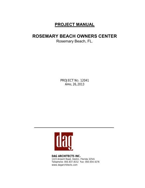
2013 4 29 ROSEMARY BEACH PROJECT MANUAL.pdf
2013 4 29 ROSEMARY BEACH PROJECT MANUAL.pdf
2013 4 29 ROSEMARY BEACH PROJECT MANUAL.pdf

Create successful ePaper yourself
Turn your PDF publications into a flip-book with our unique Google optimized e-Paper software.
<strong>PROJECT</strong> <strong>MANUAL</strong><br />
<strong>ROSEMARY</strong> <strong>BEACH</strong> OWNERS CENTER<br />
Rosemary Beach, FL.<br />
<strong>PROJECT</strong> NO. 12041<br />
APRIL 26,<strong>2013</strong><br />
DAG ARCHITECTS INC.<br />
1223 Airport Road, Destin, Florida 32541<br />
Telephone: 850.837.8152 Fax: 850.654.4276<br />
www.dagarchitects.com
DAG Architects Inc.<br />
12041 Rosemary Beach Pavilion<br />
Rosemary Beach, FL<br />
This page intentionally left blank.
DAG Architects Inc.<br />
12041 Rosemary Beach Pavilion<br />
Rosemary Beach, FL<br />
<strong>PROJECT</strong> <strong>MANUAL</strong><br />
SECTION / TITLE<br />
DIVISION 00 - BIDDING AND CONTRACT DOCUMENTS<br />
00 11 16 INVITATION TO BID<br />
00 21 13 INSTRUCTIONS TO BIDDERS<br />
00 41 00 BID FORM<br />
00 42 00 PUBLIC ENTITY CRIME STATEMENT<br />
00 42 50 DRUG-FREE WORKPLACE CERTIFICATION<br />
00 52 00 AGREEMENT FORMS<br />
00 61 13 PERFORMANCE BOND AND PAYMENT BOND<br />
00 72 00 GENERAL CONDITIONS OF THE CONTRACT FOR CONSTRUCTION<br />
00 73 00 SUPPLEMENTARY CONDITIONS OF THE CONTRACT FOR CONSTRUCTION<br />
00 73 80 WEATHER DELAY LOG<br />
SPECIFICATIONS<br />
DIVISION 01 – GENERAL REQUIREMENTS<br />
01 11 00 PRODUCT EVALUATION AND APPROVAL<br />
01 23 00 ALTERNATES<br />
01 25 00 SUBSTITUTION PROCEDURES<br />
01 26 00 CONTRACT MODIFICATION PROCEDURES<br />
01 <strong>29</strong> 00 PAYMENT PROCEDURES<br />
01 31 00 <strong>PROJECT</strong> MANAGEMENT AND COORDINATION<br />
01 32 00 CONSTRUCTION PROGRESS DOCUMENTATION<br />
01 33 00 SUBMITTAL PROCEDURES<br />
01 40 00 QUALITY REQUIREMENTS<br />
01 42 00 REFERENCES<br />
01 50 00 TEMPORARY FACILITIES AND CONTROLS<br />
01 60 00 PRODUCT REQUIREMENTS<br />
01 73 00 EXECUTION<br />
01 77 00 CLOSEOUT PROCEDURES<br />
01 78 23 OPERATION AND MAINTENANCE DATA<br />
01 78 39 <strong>PROJECT</strong> RECORD DOCUMENTS<br />
01 79 00 DEMONSTRATION AND TRAINING<br />
DIVISIONS 03 - CONCRETE<br />
03 30 00 CAST-IN-PLACE CONCRETE<br />
03 38 16 UNBONDED POST TENSIONING<br />
03 41 00 PRECAST STRUCTURAL CONCRETE<br />
DIVISIONS 04 – MASONRY<br />
04 20 00 CONCRETE MASONRY<br />
04 72 00 CAST STONE<br />
TABLE OF CONTENTS TOC - 1/4
DAG Architects Inc.<br />
12041 Rosemary Owners Center<br />
Rosemary Beach, FL<br />
SECTION / TITLE<br />
DIVISION 05 – METALS<br />
05 40 00 COLD FORMED METAL FRAMING<br />
05 50 00 METAL FABRICATIONS<br />
05 52 13 PIPE AND TUBE RAILINGS<br />
DIVISION 06 – WOOD, PLASTICS AND COMPOSITES<br />
06 10 00 ROUGH CARPENTRY<br />
06 15 16 WOOD ROOF DECKING<br />
06 15 33 WOOD STAGE DECKING<br />
06 16 00 SHEATHING<br />
06 40 23 INTERIOR ARCHITECTURAL WOODWORK<br />
06 48 00 WOOD DOOR FRAMES<br />
DIVISION 07 – THERMAL AND MOISTURE PROTECTION<br />
07 21 00 THERMAL INSULATION<br />
07 42 13.23 FORMED METAL COMPOSITE PANELS<br />
07 54 19 POLYVINYL-CHLORIDE (PVC) ROOFING<br />
07 92 00 JOINT SEALANTS<br />
DIVISION 08 – OPENINGS<br />
08 12 13 HOLLOW METAL FRAMES<br />
08 14 16 FLUSH WOOD DOORS<br />
08 41 13 ALUMINUM FRAMED ENTRANCES AND STOREFRONTS<br />
08 71 00 DOOR HARDWARE<br />
08 80 00 GLAZING<br />
08 90 00 LOUVERS & VENTS<br />
DIVISION 09 – FINISHES<br />
09 22 16 NON STRUCTURAL METAL FRAMING<br />
09 24 00 CEMENT PLASTERING<br />
09 <strong>29</strong> 00 GYPSUM BOARD<br />
09 30 00 TILING<br />
09 91 23 INTERIOR PAINTING<br />
DIVISION 10 – SPECIALTIES<br />
10 21 13.17 PHENOLIC CORE TOILET COMPARTMENTS<br />
10 28 00 TOILET ACCESSORIES<br />
10 44 13 FIRE EXTINGUISHER CABINETS<br />
10 44 16 FIRE EXTINGUISHERS<br />
DIVISION 11 – EQUIPMENT<br />
11 31 00 RESIDENTIAL APPLIANCES<br />
DIVISION 14 – CONVEYING SYSTEMS<br />
14 21 00 ELECTRIC TRACTION ELEVAYORS<br />
TABLE OF CONTENTS TOC - 2/4
DAG Architects Inc.<br />
12041 Rosemary Owners Center<br />
Rosemary Beach, FL<br />
SECTION / TITLE<br />
DIVISION 21<br />
21 13 13 BUILDING SPRINKLER AND STANDPIPE SYSTEM<br />
DIVISION 22<br />
22 01 00 PLUMBING GENERAL<br />
22 05 23 VALVES<br />
22 05 48 SUPPORTS, ANCHORS AND SEALS<br />
22 05 56 ACCESS DOORS<br />
22 05 59 TESTING, CLEANING AND STERILIZATION OF PIPING SYSTEMS<br />
22 05 63 EXCAVATION AND BACKFILL<br />
22 07 00 INSULATION FOR PLUMBING EQUIPMENT AND PIPING<br />
22 11 13 POTABLE WATER SYSTEM<br />
22 11 16 PIPES AND PIPE FITTINGS<br />
22 11 19 PIPING SPECIALTIES<br />
22 13 16 SOIL, WASTE AND VENT SYSTEM<br />
22 14 00 STORM WATER SYSTEM<br />
22 16 00 GAS SYSTEM<br />
22 30 00 PLUMBING FIXTURES<br />
DIVISION 23<br />
23 01 00 MECHANICAL GENERAL<br />
23 05 20 PIPES AND PIPE FITTINGS<br />
23 05 21 PIPING SPECIALTIES<br />
23 05 <strong>29</strong> SUPPORTS, ANCHORS AND SEALS<br />
23 05 53 MECHANICAL IDENTIFICATION<br />
23 05 93 TESTING AND BALANCING OF MECHANICAL SYSTEMS<br />
23 07 13 EXTERIOR INSULATION FOR DUCTWORK<br />
23 31 13 HVAC METAL DUCTWORK<br />
23 33 00 DUCTWORK ACCESSORIES<br />
23 34 00 FANS<br />
23 37 13 GRILLES, REGISTERS AND CEILING DIFFUSERS<br />
23 37 26 WALL LOUVERS<br />
23 81 43 AIR SOURCE UNITARY HEAT PUMPS<br />
23 81 46 WATER TO AIR HEAT PUMPS<br />
DIVISION 26<br />
26 05 00 ELECTRICAL GENERAL REQUIREMENTS<br />
26 05 19 LOW VOLTAGE ELECTRICAL POWER CONDUCTORS<br />
26 05 23 FIRESTOP SYSTEMS AND SLEEVES<br />
26 05 26 GROUNDING AND BONDING FOR ELECTRICAL SYSTEMS<br />
26 05 33 RACEWAYS AND BOXES FOR ELECTRICAL SYSTEMS<br />
26 05 53 IDENTIFICATION FOR ELECTRICAL SYSTEMS<br />
26 09 33 CENTRAL DIMMING CONTROLS<br />
26 24 16 PANELBOARDS<br />
26 27 26 WIRING DEVICES<br />
26 28 16 ENCLOSED SWITCHES AND CIRCUIT BREAKERS<br />
26 43 13 TRANSIENT VOLTAGE SUPPRESSION<br />
26 51 00 INTERIOR LIGHTING<br />
26 56 00 EXTERIOR LIGHTING<br />
TABLE OF CONTENTS TOC - 3/4
DAG Architects Inc.<br />
12041 Rosemary Owners Center<br />
Rosemary Beach, FL<br />
SECTION / TITLE<br />
DIVISION 31 – EARTHWORK<br />
31 31 16 TERMITE CONTROL<br />
END OF TABLE OF CONTENTS<br />
TABLE OF CONTENTS TOC - 4/4
DAG Architects Inc<br />
12041 <strong>ROSEMARY</strong> <strong>BEACH</strong> OWNERS CENTER<br />
<strong>ROSEMARY</strong> <strong>BEACH</strong>, FLORIDA<br />
SECTION 00 11 16 - INVITATION TO BID<br />
<strong>PROJECT</strong><br />
Rosemary Beach Owners Center<br />
Rosemary Beach, Florida<br />
LOCATION<br />
Rosemary Beach, Florida<br />
OWNER<br />
Rosemary Beach Owners Center<br />
Rosemary Beach, Florida<br />
ARCHITECT<br />
DAG Architects, Inc.<br />
1223 Airport Road<br />
Destin, Florida 32541<br />
Telephone: 850.837.8152<br />
Fax: 850.654.4276<br />
Civil Engineer<br />
Preble-Rish Consulting Engineers<br />
324 Marina Drive<br />
Port St. Joe, Florida 32456<br />
Telephone: 850.277.7200<br />
Fax : 850.227.7215<br />
Contact: Chance Powell (powellc@preble-rish.com)<br />
Structural Engineer<br />
Anderson Engineers<br />
78 Ricker Ave.<br />
Santa Rosa Beach, Florida 32459<br />
Telephone: 850.231.4540<br />
Contact: Terry Anderson (terry@andersonengineers.net.<br />
Plumbing/Mechanical<br />
David Watford, PE<br />
Engineering Inc.<br />
4471 Clinton St.<br />
Marianna, FL 32446<br />
Telephone: 850.526.3447<br />
Contact: David Watford (david@watford-engineering.com)<br />
Electrical Engineer<br />
Humber-Garick Consulting Engineers<br />
207 Ferry Road SE<br />
Fort Walton Beach, Florida<br />
Telephone: 850.243.6723<br />
Fax: 850.664.5420<br />
Contact: Chris Garick (cgarick@h-gce.com)<br />
INVITATION TO BID 00 11 16 - 1
DAG Architects Inc<br />
12041 <strong>ROSEMARY</strong> <strong>BEACH</strong> OWNERS CENTER<br />
<strong>ROSEMARY</strong> <strong>BEACH</strong>, FLORIDA<br />
Contractors for Rosemary Beach Amphitheater are invited to bid on a General Contract, including New<br />
Construction for an Owners Center at Rosemary Beach, Florida. All bids must be on a lump-sum basis;<br />
segregated bids will not be accepted. All items and conditions below are a part of this request, and no bid<br />
will be accepted unless all these conditions have been complied with.<br />
Rosemary Beach Owners Center will receive sealed bids until 3:00pm Monday May 20, <strong>2013</strong>. Bids may be<br />
hand delivered to DAG Architects Office Destin, Florida. Please note on the exterior of the envelope “Bid<br />
Enclosed, “Rosemary Beach Owners Center” Bid”. Bids may also be sent electronically to Roger Godwin,<br />
AIA, DAG Architects. rgodwin@dagarchitects.com.<br />
A Prebid Meeting is scheduled at the Project site for Monday May6, <strong>2013</strong>. Architect to establish time at later<br />
date.<br />
Bids received after that time will not be accepted. All Bids will be opened privately.<br />
ACCESS TO BIDDING DOCUMENTS<br />
Copies of the Bidding documents will be available at the Architect’s Office and will be emailed to the 3<br />
selected General Contractors.<br />
DAG Architects, Inc.<br />
1223 Airport Road<br />
Destin, Florida 32541<br />
(850) 837-8152<br />
And at F.W. Dodge Corporation, 1311 Executive Center, Suite 108, Tallahassee, Florida.<br />
And at F.W. Dodge Corporation, 201 South “F” Street, Pensacola, Florida<br />
CONTRACT SECURITY<br />
Successful Bidder will be required to furnish a “performance bond” and “labor and material payment bond” in<br />
the amount of 100% of his contract amount.<br />
PROCUREMENT OF BIDDING DOCUMENTS<br />
General Contractors may obtain complete sets of Bidding Documents by reserving through the Bidder<br />
Contact at DAG Architect’s office. General Contractors will be provided documents specs and drawings in<br />
electronic format, <strong>pdf</strong> files on CD.<br />
Bidders shall use complete set of Bidding Documents in preparing bids; neither the Owner nor the Architect<br />
assume any responsibility for errors or misinterpretations resulting from the use of incomplete sets.<br />
Bids will be opened privately and the contractors will be notified at a later date.<br />
In accordance with the Instructions to Bidders, each bid must include:<br />
1. Bid Form<br />
2. Bid Security<br />
3. List of Subcontractors<br />
4. Florida Public Entity Crimes statement.<br />
5. Drug-Free Workplace certification<br />
6. Additional Requirements per Section Instructions To Bidders, 00 21 13, 1.22, Qualifications, Staffing<br />
Outline, and Construction Schedule.<br />
INVITATION TO BID 00 11 16 - 2
DAG Architects Inc<br />
12041 <strong>ROSEMARY</strong> <strong>BEACH</strong> OWNERS CENTER<br />
<strong>ROSEMARY</strong> <strong>BEACH</strong>, FLORIDA<br />
RIGHTS RESERVED BY OWNER<br />
The owner reserves the right to reject any or all proposals and to waive any irregularities in bidding, or to<br />
accept the lowest responsible proposal that in the opinion of the owner will serve the best interest of the<br />
owner. The owner will not be obligated to accept the lowest proposal. The owner further reserves the right<br />
to approve all subcontractors.<br />
WITHDRAWAL OF PROPOSALS<br />
No proposals may be withdrawn for a period of thirty (30) days after the receipt of proposals.<br />
END OF INVITATION TO BID<br />
“LEFT BLANK”<br />
INVITATION TO BID 00 11 16 - 3
DAG Architects Inc<br />
12041 <strong>ROSEMARY</strong> <strong>BEACH</strong> OWNERS CENTER<br />
<strong>ROSEMARY</strong> <strong>BEACH</strong>, FLORIDA<br />
INVITATION TO BID 00 11 16 - 4
DAG Architects Inc<br />
12041 <strong>ROSEMARY</strong> <strong>BEACH</strong> OWNERS CENTER<br />
<strong>ROSEMARY</strong> <strong>BEACH</strong>, FL.<br />
SECTION 00 21 13 - INSTRUCTIONS TO BIDDERS<br />
PART 1 - GENERAL<br />
1.1 SUMMARY<br />
A. The Drawings and Project Manual cover new construction for the Rosemary Beach Owners<br />
Center, Rosemary Beach, Florida.<br />
1.2 PROCUREMENT OF BIDDING DOCUMENTS<br />
A. Invited General Contractors will be provided electronic files in <strong>pdf</strong> format. These files will be<br />
emailed by way of a download service.<br />
1.3 EXAMINATION OF BIDDING DOCUMENTS AND SITE<br />
A. Prior to submitting a Bid, each bidder shall carefully examine the Bidding Documents. Each<br />
bidder shall fully inform him/herself prior to bidding as to all limitations under which the work is<br />
to be performed and shall include in his/her bid a sum to cover the costs of all items necessary<br />
to perform that work as set forth in the Contract Documents.<br />
B. Bidders are encouraged to visit the construction site at Rosemary Beach, Florida.<br />
C. No allowance will be made to any Bidder because of lack of such examination or knowledge.<br />
The submission of a Bid will be construed as conclusive evidence that the Bidder has made such<br />
an examination.<br />
1.4 INTERPRETATIONS AND ADDENDA<br />
A. The Bidder shall carefully examine and compare the Bidding Documents, site and local<br />
conditions with each other and no later than ten (10) days prior to the date for receipt of Bids,<br />
make a written request to the Architect for interpretation or correction of any errors,<br />
ambiguities or inconsistencies found during his examination.<br />
B. Interpretations, corrections and change to the Bidding Documents will be made by Addendum.<br />
Addendums will be mailed, faxed or emailed to each Bidder of record. The Architect and the<br />
Owner will not be responsible for interpretations, corrections or changes made in any other<br />
manner, and the Bidder shall not rely on them<br />
C. Any item, material, condition, service, etc. that may be alluded to in the drawings or<br />
specifications, and that is not clearly understood by the bidder as to the Architects intent, shall<br />
be clarified by the bidder prior to the Bid. Failure to clarify any ambiguity shall not relieve the<br />
bidder from supplying the intent of the Architect as part of the base contract.<br />
1.5 SUBSTITUTIONS (Prior to bidding)<br />
A. Substitutions will be considered prior to receipt of Bids only if a written request for approval is<br />
submitted to the Architect no later than ten (10) days prior to the date for receipt of Bids. Each<br />
request shall include a complete description of the proposed substitution, along with drawings,<br />
performance and test data, any other information required for a complete evaluation. The<br />
Architect’s decision of approval or disapproval will be final. If the Architect approves the<br />
proposed substitution, such approval will be set forth in addenda. Bidders shall not rely on<br />
approvals made in any other manner.<br />
B. Substitutions will be considered after the Contract award only if they are in compliance with the<br />
conditions set in Division 1 Section “Product Requirements.”<br />
C. Substitution Request Form: Use CSI Form 13.1A.<br />
INSTRUCTIONS TO BIDDERS 00 21 13 -1
DAG Architects Inc<br />
12041 <strong>ROSEMARY</strong> <strong>BEACH</strong> OWNERS CENTER<br />
<strong>ROSEMARY</strong> <strong>BEACH</strong>, FL.<br />
1.6 FAMILIARITY WITH LAWS<br />
A. The Bidder shall be familiar with all Federal, State and local laws, ordinances, rules and<br />
regulations affecting the Work including all requirements of the Rosemary Beach Community. .<br />
Ignorance of them on the part of Bidder shall in no way relieve the Bidder from responsibility.<br />
1.7 FLORIDA PRODUCTS AND LABORS<br />
A. The Bidder’s attention is called to Section 255.04 of the Florida Statutes which requires that on<br />
public building contracts, Florida products and labor shall be used for public building contracts<br />
whenever price and quality are the same as products and labor specified.<br />
1.8 TIME OF COMPLETION<br />
A. The Owner request you provide a Staffing and Construction Schedule with your proposal.<br />
1.9 PREPARATION AND SUBMISSION OF BIDS<br />
A. All bids shall be submitted on a lump sum basis; segregated Bids will not be accepted. Each<br />
bidder shall copy the Bid Form in duplicate on to the Bidder’s letterhead and indicate the Bid<br />
price, Alternate prices and other required information in the proper spaces. Any interlineations,<br />
alterations, and erasures must be initialed by the signer of the Bid. Bids containing any<br />
conditions or irregularities of any kind may be rejected by the Owner. All bids must be<br />
submitted on the form provided by the Owner and must be signed by an authorized<br />
representative of the company placing the bid.<br />
B. Submit the Bid forms, List of Subcontractors, Bid Security, Florida Public Entity Crime Statement<br />
and Drug-Free Workplace Certification in a sealed opaque envelope addressed to the Owner<br />
and identified with the project name and the Bidder’s name and address. It is the sole<br />
responsibility of the Bidder to see that the bid is received on time.<br />
C. Disclosure Requirement (Florida Statues, Chapter 112): Each bid is subject to the provisions of<br />
Florida Statutes, Chapter 112, providing that all bidders must disclose with the bid submittal the<br />
name of any officer, director or agent who is also a public officer or an employee of the Beach<br />
Community Bank. Further, all bidders must disclose the name of any City officer or employee<br />
who owns, directly or indirectly, an interest of five percent or more in the bidding firm.<br />
1.10 LISTING OF SUBCONTRACTORS<br />
A. In order that the Owner may be assured that only qualified and competent subcontractors will<br />
be employed on this project, each Bidder shall submit with his/her proposal a list of the<br />
subcontractors who will perform the work for each division of the specifications, as indicated by<br />
the “List of Subcontractors” form contained in these specifications. The bidder shall have<br />
determined to his/her own complete satisfaction that a listed subcontractor has been<br />
successfully engaged this particular type of business for a reasonable length of time, has<br />
successfully completed installations comparable to that which is required by this agreement and<br />
is qualified both technically and financially to perform that pertinent phase of work for which he<br />
is listed. Only one subcontractor shall be listed for each phase of work.<br />
B. It is also specified in a Division 1 Section that, in addition to foregoing, The Owner reserves the<br />
right to approve all subcontractors before work is started and that a complete list of all<br />
subcontractors shall be submitted.<br />
1.11 DISQUALIFICATION OF BIDDERS<br />
INSTRUCTIONS TO BIDDERS 00 21 13 -2
DAG Architects Inc<br />
12041 <strong>ROSEMARY</strong> <strong>BEACH</strong> OWNERS CENTER<br />
<strong>ROSEMARY</strong> <strong>BEACH</strong>, FL.<br />
A. More than one bid from an individual, firm, partnership, corporation or association under the<br />
same or different names will not be considered. Reasonable grounds for believing that the<br />
bidder is interested in more than one bid for the same work will cause rejection of all bids in<br />
which such Bidder is believed to be interested. Bids will be rejected if there is reason to believe<br />
that collusion exists between Bidders. Bids in which the price is obviously unbalanced may be<br />
rejected.<br />
1.12 OPENING OF BIDS<br />
A. Bids will be opened privately. Contractor will be notified at a later time.<br />
1.13 MODIFICATION AND WITHDRAWAL OF BIDS<br />
A. A submitted Bid may be substituted, replaced or withdrawn in its entirety, prior to the date and<br />
time designated for receipt of Bids, by notifying the party receiving the Bids at the place<br />
designated for receipt of Bids. Notification shall be in writing over the signature of the Bidder.<br />
Such notification shall be received by the end of the business day prior to the day designated to<br />
receive bids.<br />
1.14 EVALUATION AND CONSIDERATION OF BIDS<br />
A. It is the intent of the Owner to award the Contract to the lowest responsible Bidder provided<br />
the Bid has been submitted in accordance with the requirements of the Bidding Documents and<br />
does not exceed the funds available. The Owner shall have the right to waive informalities or<br />
irregularities in a Bid received and to accept the Bid, which in the Owner's judgment, is in the<br />
best interest of the Owner.<br />
B. The Owner reserves the right to award to other than the lowest responsible bidder if sufficient<br />
reasons exist that a bidder other than the lowest is more responsive. If the bid is not awarded<br />
to the lowest bidder, a full and complete statement of the reasons for awarding the contract<br />
otherwise shall be prepared by the Owner and filed with documents relating to the bid award.<br />
1.15 REJECTION OF BIDS<br />
A. The Owner reserves the right to waive minor defects in the process, to reject any or all Bids<br />
when such rejection is in the best interest of the Owner, to reject a Bid not accompanied by a<br />
Bid Security, or to reject a bid if not in the best interest of the Owner, or to reject a Bid, which<br />
is in any way irregular or incomplete.<br />
1.16 OWNER’S FINANCIAL CAPACITY<br />
A. The Owner shall furnish evidence that financial arrangements have been made to fulfill the<br />
Owner's obligations under the Contract to the Bidder under consideration for award of Contract,<br />
if requested, no later than seven days prior to the expiration of the time for withdrawal of bids.<br />
If reasonable evidence is not furnished, the Bidder will not be required to execute the<br />
Agreement between the Owner and the Contractor.<br />
1.17 SUBMITTAL<br />
A. The Bidder shall furnish to the Owner through the Architect in writing a designation of work to<br />
be done by his own forces, names of the manufacturers, products and suppliers of principal<br />
items or systems of materials and equipment proposed for the work, names of persons or<br />
entities proposed for the principal portions of the work.<br />
INSTRUCTIONS TO BIDDERS 00 21 13 -3
DAG Architects Inc<br />
12041 <strong>ROSEMARY</strong> <strong>BEACH</strong> OWNERS CENTER<br />
<strong>ROSEMARY</strong> <strong>BEACH</strong>, FL.<br />
B. Prior to award of the Contract the Architect will notify the Bidder in writing if either the Owner<br />
or the Architect, after due investigation, has reasonable objection to any person or entity<br />
proposed by the Bidder. The Bidder may, at his option, withdraw his bid or submit a substitute<br />
with an adjustment in the Base Bid or Alternate Bid to cover the cost occasioned by the<br />
substitution. The Owner may accept the adjusted price or disqualify the Bidder. In either<br />
event the bid security will not be forfeited.<br />
C. Persons and entities proposed for the work of which the Owner and the Architect have No<br />
objection shall not be changed except with the written consent of the Owner and the Architect.<br />
1.18 BID BOND<br />
A. The Bidder shall furnish a Bid Bond for not less than 5% of the Base Bid sum, nor more than<br />
$10,000.00 payable to the Owner, must be attached to the bid. Bid Bond shall be on bonds in<br />
this State, have power-of-attorney attached, and be dated within 15 days of date of opening.<br />
Bid Bonds of three lowest bidders will be retained until Contract and Bonds are properly<br />
executed by the successful bidder; all others will be returned upon request immediately after<br />
tabulation and checking of bids. The Bid Security shall insure that the bidder will enter into a<br />
contract with the Owner and will furnish the specified Performance and Payment Bonds and<br />
evidence of insurance within 10 days after presentation to him of a contract draft, provided<br />
such presentation is made within 90 days of the Bid Date. The monies represented by the Bid<br />
Security (limited to the difference to the next lower bid) shall be forfeited to the Owner as<br />
proper compensation for any damage resulting from a default of this condition.<br />
1.19 PERFORMANCE BOND AND PAYMENT BOND<br />
A. The Bidder shall execute and deliver to Owner a Performance Bond and a Labor and Materials<br />
Payment Bond with a surety insurer authorized to do business in this state as a surety, each in<br />
the amount of 100% of the Contract Sum in accordance with the General Conditions and<br />
Supplementary Conditions. Before commencing the work, Bidder shall be required to record<br />
the bonds in the public records of Walton County.<br />
1.20 COST BREAKDOWN<br />
A. The successful bidder will be required to submit, at the start of the job, and prior to the first<br />
application for payment, a breakdown of construction costs (Schedule of Values), itemized, to<br />
be used for accounting purposes.<br />
1.21 OWNERS RIGHTS<br />
A. The Owner reserves the right to reject any or all Bids when such rejection is in the best interest<br />
of the Owner, to reject a Bid not accompanied by a Bid Security, to reject a Bid which is in any<br />
way irregular or incomplete, or to withdraw the request for Bids.<br />
1.22 ADDITIONAL REQUIREMENTS<br />
A. The owner request that each bidder provide the following information in a sealed package<br />
separate from the Bid:<br />
1. Submit your qualifications for this project describing similar types of project completed<br />
listing building user contact information if owner desires to contact them.<br />
2. Submit staffing outline for the project including Superintendents, project managers, etc.,<br />
by name identifying, experience, and time with company.<br />
3. Submit Construction Schedule for the project.<br />
END OF SECTION 00 21 13<br />
INSTRUCTIONS TO BIDDERS 00 21 13 -4
DAG Architects Inc<br />
10059 <strong>ROSEMARY</strong> <strong>BEACH</strong> AMPHITHEATER<br />
<strong>ROSEMARY</strong>, FL.<br />
SECTION 00 41 00 - BID FORM<br />
Bidders Name:<br />
Legal Address:<br />
Telephone No.:<br />
Proposal For:<br />
Project Name:<br />
GENERAL CONSTRUCTION WORK<br />
Rosemary Beach Owners Center, Rosemary Beach, Florida<br />
DAG Project No.: 12041<br />
Gentlemen:<br />
I have received the Bidding Documents, consisting of Drawings and Project Manual, entitled Rosemary<br />
Beach Amphitheater, as prepared by DAG Architects Inc., 1223 Airport Road, Destin, Florida 32541. I have<br />
also received Addenda numbers ____________________ and have included their provisions in my Bid. I<br />
have examined both the Bidding Documents and the site and submit the following bid.<br />
In submitting the Bid, I agree:<br />
1. To hold my Bid in full force and effect for a period of thirty (30) calendar days after the date of the<br />
opening of this Bid.<br />
2. To enter into and execute a Contract within fifteen (15) calendar days after said Contract is<br />
delivered to me, if awarded said Contract on the basis of this Bid, and to furnish Performance Bonds<br />
and Labor and Material Payment Bonds in accordance with the General Conditions.<br />
3. To accomplish the work in accordance with the Contract Documents and to commence such work on<br />
or before the date to be specified by the Architect in the written “Notice to Proceed” and to<br />
substantially complete the Project as stated in the Staffing and Construction Schedule I submit with<br />
this Proposal.<br />
I will construct this Project (Base Bid) for the lump sum price as listed:<br />
Base Bid<br />
Dollars<br />
($ ), which amount includes the following addenda:<br />
ALTERNATE NO 1: Bocce Ball Courts<br />
Add/Deduct:___________________________________________________dollars ($__________________).<br />
ALTERNATE NO 2: Dog Park<br />
Add/Deduct:___________________________________________________dollars ($__________________).<br />
ALTERNATE NO 3: Greenwall<br />
Add/Deduct:___________________________________________________dollars ($__________________).<br />
ALTERNATE NO 4:Sliding Doors<br />
Add/Deduct:___________________________________________________dollars ($__________________).<br />
BID FORM 00 41 00 - 1
DAG Architects Inc<br />
10059 <strong>ROSEMARY</strong> <strong>BEACH</strong> AMPHITHEATER<br />
<strong>ROSEMARY</strong>, FL.<br />
The undersigned hereby agrees to complete the work as stated in the attached Staffing and Construction<br />
Schedule I submitted with this proposal.<br />
Florida Construction Industries Licensing Board Certification:<br />
________________________________<br />
(Name of Holder)<br />
_______________________<br />
(Certificate No.)<br />
FIRM: __________________________________________________________<br />
(Name of Firm)<br />
BY:<br />
__________________________________________________________<br />
(Signature of Bidder)<br />
__________________________________________________________<br />
(Name of Bidder)<br />
TITLE: __________________________________________________________<br />
(Title of Bidder)<br />
DATE: __________________________________________________________<br />
ATTACHMENTS:<br />
Bid Form<br />
List of Subcontractors<br />
Bid Bond.<br />
Public Entity Crime Statement<br />
Drug-Free Workplace Certificate<br />
Additional Requirements per Instructions To Bidders, 00 21 13, 1.22, Qualifications, Staffing Outline, and<br />
Construction Schedule.<br />
END OF SECTION 00 41 00<br />
BID FORM 00 41 00 - 2
DAG Architects Inc<br />
12041 Rosemary Beach Owners Center<br />
Rosemary Beach Fl.<br />
SECTION 00 42 00 - PUBLIC ENTITY CRIMES STATEMENT<br />
A. The following information is included in these bid documents as required by Florida<br />
Statute.<br />
B. All invitations to bid as defined by Section 287.012(11), Florida Statutes; requests for<br />
proposals as defined by Section 287.012(16), Florida Statutes; and any contract<br />
document described by Section 287.058, Florida Statutes, shall contain a statement<br />
informing persons of the provisions of paragraph (2)(a) of Section 287.133, Florida<br />
Statutes.<br />
C. A copy of the Sworn Statement form is contained herein. The completed form shall be<br />
submitted in the bid submittal along with the other required documents.<br />
PUBLIC ENTITY CRIMES STATEMENT 00 42 00 - 1
DAG Architects Inc<br />
12041 Rosemary Beach Owners Center<br />
Rosemary Beach Fl.<br />
SWORN STATEMENT UNDER SECTION 287.133 (3) (A)<br />
FLORIDA STATUES, ON PUBLIC ENTITY CRIMES<br />
THIS FORM MUST BE SIGNED IN THE PRESENCE OF A NOTARY PUBLIC OR OTHER OFFICER<br />
AUTHORIZED TO ADMINISTER OATHS.<br />
1. This sworn statement is submitted with Bid, Proposal or Contract for<br />
2. This sworn statement is submitted by<br />
whose business address is<br />
and (if applicable) Federal Employer Identification Number (FEIN) is<br />
(If the entity has no<br />
FEIN, include the Social Security Number of the individual signing this sworn statement:<br />
3. My name is and my relationship to the entity named above is<br />
4. I understand that a "public entity crime" as defined in Paragraph 287.133 (1) (g). Florida<br />
Statutes, means a violation of any state or federal law by a person with respect to and directly related<br />
to the transaction of business with any public entity or with an agency or political subdivision of any<br />
other state or with the United States, including, but not limited to, any bid or contract for goods or<br />
services to be provided to any public entity or any agency or political subdivision of any other state or of<br />
the United States and involving antitrust, fraud, theft, bribery, collusion, racketeering, conspiracy, or<br />
material misrepresentation.<br />
5. I understand that "convicted" or "convicted" as defined in paragraph 287.133 (1) (b), Florida<br />
Statutes, means a finding of guilt or a conviction of a public entity crime with or without an adjudication<br />
of guilt, in any federal or state trial court of records relating to charges brought by indictment or<br />
information after July 1, 1989, as a result of a jury verdict, non-jury trial, or entry of a plea of guilty or<br />
nolo contendere.<br />
6. I understand that an "affiliate" as defined in Paragraph 287 .133 (1) (a), Florida Statutes,<br />
means:<br />
1. A predecessor or successor of a person convicted of a public entity crime; or<br />
2. An entity under the control of any natural person who is active in the management of<br />
the entity and who has been convicted of a public entity crime. The term " affiliate" includes those<br />
officers, directors, executives, partners, shareholders, employees, members, and agents who are active<br />
in the management of an affiliate. The ownership by one of shares constituting a controlling income<br />
among persons when not for fair interest in another person, or a pooling of equipment or income<br />
among persons when not for fair market value under an length agreement, shall be a prima facie case<br />
that one person controls another person. A person who knowingly convicted of a public entity crime, in<br />
Florida during the preceding 36 months shall be considered an affiliate.<br />
7. I understand that a "person" as defined in paragraph 287 .133 (1) (e), Florida Statutes, means<br />
any natural person or entity organized under the laws of the state or of the United States with the legal<br />
power to enter into a binding contract provision of goods or services let by a public entity, or which<br />
otherwise transacts or applies to transact business with a public entity. The term "person" includes<br />
those officers, directors, executives, partners, shareholders, employees, members, and agents who are<br />
active in management of an entity.<br />
PUBLIC ENTITY CRIMES STATEMENT 00 42 00 - 2
DAG Architects Inc<br />
12041 Rosemary Beach Owners Center<br />
Rosemary Beach Fl.<br />
8. Based on information and belief, the statement which I have marked below is true in relation to<br />
the entity submitting this sworn statement. (Please indicate which statement applies)<br />
Neither the entity submitting this sworn statement, nor any officers, directors,<br />
executive, partners, shareholders, employees. member, or agents who are active in management of the<br />
entity, nor affiliate of the entity have been charged with and convicted of a public entity crime<br />
subsequent to July 1, 1989.<br />
The entity submitting this sworn statement, or one or more of the officers, directors,<br />
executives, partners, shareholders, employees, members, or agents who are active in management of<br />
the entity, or an affiliate of the entity has been charged with and convicted of a public entity crime<br />
subsequent to July 1, 1989 And (please attach a copy of the final order)<br />
The person or affiliate was placed on the convicted vendor list. There has been a<br />
subsequent proceeding before a hearing officer of the State of Florida, Division of Administrative<br />
Hearings. The final order entered by the hearing officer determined that it was in public interest to<br />
remove the person or affiliate from the convicted vendor list. (please attach a copy of the final order.)<br />
The person or affiliate has not been placed on the convicted vendor list. (Please<br />
describe any action taken by, or pending with, the department of General Services.)<br />
STATE OF FLORIDA<br />
COUNTY OF<br />
(Signature)<br />
Date:<br />
PERSONALLY APPEARED BEFORE ME, the undersigned authority,<br />
who, after first being sworn by me, affixed his/her signature at the space provided above on this<br />
day of , 20 , and is personally known to me, or has provided _ as<br />
identification.<br />
My Commission expires:<br />
Notary Public<br />
END OF SECTION 00 42 00<br />
PUBLIC ENTITY CRIMES STATEMENT 00 42 00 - 3
DAG Architects Inc<br />
12041 Rosemary Beach Owners Center<br />
Rosemary Beach Fl.<br />
“LEFT BLANK”<br />
PUBLIC ENTITY CRIMES STATEMENT 00 42 00 - 4
DAG Architects Inc<br />
12041 Rosemary Beach Owners Center<br />
Rosemary Beach Fl.<br />
SECTION 00 42 50 – DRUG-FREE WORKPLACE CERTIFICATION 1-3-<strong>2013</strong><br />
A. A copy of the Drug-Free Certification form is contained herein. The completed form<br />
must be submitted in the bid submittal along with the other required documents.<br />
PUBLIC ENTITY CRIMES STATEMENT 00 42 50 - 1
DAG Architects Inc<br />
12041 Rosemary Beach Owners Center<br />
Rosemary Beach Fl.<br />
DRUG-FREE WORKPLACE CERTIFICATION<br />
The below signed bidder certifies that it has implemented a Drug-Free Workplace Program. In order to<br />
have a Drug-Free Workplace Program, a business shall:<br />
1. Publish a statement notifying employees that the unlawful manufacture, distribution, dispensing,<br />
possession, or use of a controlled substance is prohibited in the workplace and specifying the actions that<br />
will be taken against employees for violations of such prohibition.<br />
2. Inform employees about the dangers of drug abuse in the workplace, the business's policy of<br />
maintaining a drug-free workplace, any available drug counseling rehabilitation and employee assistance<br />
programs and the penalties that may be imposed upon employees for drug abuse violations.<br />
3. Give each employee engaged in providing the commodities or contractual services that are under<br />
proposal a copy of the statement specified in subsection 1.<br />
4. In the statement specified in subsection 1., notify the employees that, as a condition of working<br />
on the commodities or contractual services that are under proposal, the employee will abide by the terms<br />
of the statement and will notify the employer of any conviction of, or plea of guilty or nolo contendere to,<br />
any violation occurring in the workplace no later than five (5) working days after such conviction.<br />
5. Impose a sanction on, or require the satisfactory participation in drug abuse assistance or<br />
rehabilitation program of such is available in the employee's community, by any employee who is<br />
convicted.<br />
6. Make a good faith effort to continue to maintain a drug-free workplace through implementation of<br />
this section.<br />
As the person authorized to sign this statement, I certify that this firm complies fully with the above Drug-<br />
Free Workplace requirements.<br />
DATE: _____________________________<br />
COMPANY: ________________________________________________________<br />
ADDRESS: ________________________________________________________<br />
CITY: _______________________ STATE: ____ ZIP CODE: _________<br />
TELEPHONE: __________________<br />
SIGNATURE: __________________________________ NAME<br />
(PRINTED):____________________________<br />
TITLE: ________________________________________<br />
ND OF SECTION 00 42 50<br />
PUBLIC ENTITY CRIMES STATEMENT 00 42 50 - 2
DAG Architects Inc<br />
12041 <strong>ROSEMARY</strong> <strong>BEACH</strong> OWNERS CENTER<br />
<strong>ROSEMARY</strong> <strong>BEACH</strong>, FL.<br />
SECTION 00 52 00 – AGREEMENT FORMS<br />
The “Standard Form of Agreement Between Owner and Contractor Where the Basis of Payment is a<br />
Stipulated Sum,” The American Institute of Architects (AIA) Document A101-1997, 1997 Edition, Six (6)<br />
Pages, is reference only. Document shall be issued, as modified, on this Project as the Agreement Form.<br />
Copy upon request.<br />
AGREEMENT FORM 00 52 00 - 1
DAG Architects Inc<br />
12041 <strong>ROSEMARY</strong> <strong>BEACH</strong> OWNERS CENTER<br />
<strong>ROSEMARY</strong> <strong>BEACH</strong>, FL.<br />
“LEFT BLANK”<br />
AGREEMENT FORM 00 52 00 - 2
DAG Architects<br />
12041 Rosemary Beach Owners Center<br />
Rosemary Beach Fl.<br />
SECTION 00 61 13 - PERFORMANCE BOND AND PAYMENT BOND<br />
A. The "Performance Bond and Payment Bond", The American Institute of Architects' (AIA)<br />
Document A312, March 1987 Edition, Seven (7) pages, is reference only. The<br />
documents shall be used on this Project as the Performance Bond and Payment Bond.<br />
Copies upon request.<br />
END OF SECTION 00 61 13<br />
PERFORMANCE BOND AND PAYMENT BOND 00 61 13 -1
DAG Architects<br />
12041 Rosemary Beach Owners Center<br />
Rosemary Beach Fl.<br />
“LEFT BLANK”<br />
PERFORMANCE BOND AND PAYMENT BOND 00 61 13 -2
DAG Architects Inc<br />
12041 Rosemary Beach Owners Center<br />
Rosemary Beach, FL.<br />
SECTION 00 72 00 – GENERAL CONDITIONS OF THE CONTRACT FOR<br />
CONSTRUCTION<br />
The “General Conditions of the Contract for Construction”, the American Institute of Architects (AIA)<br />
Document A201-1997, Fifteenth Edition, 1997, forty (40) pages, is referenced only.<br />
GENERAL CONDITIONS OF THE CONTRACT FOR CONSTRUCTION 00 72 00 - 1
DAG Architects Inc<br />
12041 Rosemary Beach Owners Center<br />
Rosemary Beach, FL.<br />
“LEFT BLANK”<br />
GENERAL CONDITIONS OF THE CONTRACT FOR CONSTRUCTION 00 72 00 - 2
DAG Architects Inc<br />
12041 Rosemary Beach Owners Center<br />
Rosemary Beach, FL.<br />
SECTION 00 73 00 - SUPPLEMENTARY CONDITIONS OF THE CONTRACT FOR<br />
CONSTRUCTION A201-1997<br />
PART 1 – STANDARD GENERAL CONDITIONS<br />
A. The “General Conditions of the Contract for Construction” of the American Institute of<br />
Architects, AIA Document No. A201-1997, inclusive, is a part of this Contract, it is incorporated<br />
herein.<br />
B. Additional copies of the “General Conditions” may be purchased from the Florida Association,<br />
The American Institute of Architects, Document Department, P. O. Box 10388, Tallahassee,<br />
Florida, 32302.<br />
C. The Contractor is hereby specifically directed, as a condition of the Contract, to acquaint himself<br />
with the Articles contained therein and to notify and appraise all Subcontractors, Suppliers and<br />
any other parties of the Contract or individuals or agencies engaged in the work as to its<br />
contents.<br />
D. No contractual adjustments shall be due or become exigent as a result of, or failure on the part<br />
of the Contractor to fully acquaint himself and all other parties to the contract with the<br />
conditions of Document A201.<br />
PART 2 – SUPPLEMENTARY CONDITIONS<br />
The following supplements modify, change, delete from or add to the "General Conditions of the Contract for<br />
Construction", AIA Document A201, Fifteenth Edition 1997. Where a portion of the General Conditions is<br />
modified or deleted by these Supplementary Conditions, the unaltered portions of the General Conditions<br />
shall remain in effect. Where any Article of the General Conditions is modified or any Paragraph,<br />
Subparagraph or Clause thereof is modified or deleted by these supplements, the unaltered provisions of<br />
that Article, Paragraph, Subparagraph or clause shall remain in effect.<br />
ARTICLE 1; GENERAL PROVISIONS<br />
1.2 CORRELATION AND INTENT OF THE CONTRACT DOCUMENTS<br />
Add the following Subparagraph 1.2.1.1 to 1.2:<br />
1.2.1.1 In the event of conflicts or discrepancies among the Contract Documents, interpretations will be<br />
based on the following priorities:<br />
1. The Agreement.<br />
2. Addenda, with those of later date having precedence over those of earlier date.<br />
3. The Supplementary Conditions.<br />
4. The General Conditions of the Contract for Construction.<br />
5. Drawings and Specifications.<br />
In the case of an inconsistency between Drawings and Specifications or within either Document not clarified<br />
by addendum, the better quality or greater quantity of Work shall be provided in accordance with the<br />
Architect’s interpretation.<br />
SUPPLEMENTARY CONDITIONS OF THE CONTRACT FOR CONSTRUCTION 00 73 00 -1
DAG Architects Inc<br />
12041 Rosemary Beach Owners Center<br />
Rosemary Beach, FL.<br />
ARTICLE 2; OWNER<br />
2.2 INFORMATION AND SERVICES REQUIRED OF THE OWNER<br />
Delete Subparagraph 2.2.5 and substitute the following:<br />
2.2.5 The Contractor will be furnished Construction Documents (Drawings and Project Manuals) returned<br />
to the Architects office and PDF,s for the reproduction as required for construction of this project.<br />
All copies are the responsibility of the contractor.<br />
ARTICLE 3; CONTRACTOR<br />
3.2 REVIEW OF CONTRACT DOUCMENTS AND FIELD CONDITIONS BY CONTRACTOR<br />
Add the following to the end of Subparagraph 3.2.2:<br />
Prior to commencing any excavation or grading, the Contractor shall satisfy himself as to the accuracy of all<br />
survey data as indicated in these Drawings and Specifications and/or as provided by Owner. Should the<br />
Contactor discover any inaccuracies, errors, or omissions in the survey data, the Contractor shall immediately<br />
notify the Architect in order that proper adjustments can be anticipated and ordered.<br />
Add the following Subparagraphs 3.2.4, 3.2.5, 3.2.6, and 3.2.7, to 3.2<br />
3.2.4 If, in Contractor’s opinion, any work is indicated on Drawings, or is specified in such as manner as<br />
will make it impossible to produce a generally acceptable piece of work, or should discrepancies<br />
appear between drawings and specifications, he shall refer it to Architect for decision before<br />
proceeding with Work.<br />
3.2.5 If Contractor fails to make such reference, no excuse will thereafter be entertained for failure to<br />
carry our work in satisfactory manner. Should a conflict occur in or between Drawings or<br />
Specifications, Contractor shall be deemed to have estimated on a more expensive way of doing<br />
work unless he shall have asked for and obtained a decision, in writing, from Architect before<br />
submission of proposal as to which method or materials will be required.<br />
3.2.6 Figures govern scale dimensions and large scale drawings govern those of smaller scale. If<br />
drawings and specifications conflict or require any clarification that was not obtained prior to<br />
bidding, the Contractor shall estimate and include in his bid the more expensive method or material.<br />
No deviation shall be made from plans and specifications except upon written order of the<br />
Architect.<br />
3.2.7 Contractor shall, within fifteen (15) days after signing of Contract, file with the Architect, a correct,<br />
complete itemized schedule of materials and subdivisions of work, giving quantities and unit prices<br />
of complete labor and materials.<br />
3.3 SUPERVISION AND CONSTRUCTION PROCEDURES<br />
Add the following Subparagraphs 3.3.4, 3.3.5, 3.3.6, 3.3.7, and 3.3.8 to 3.3:<br />
3.3.4 The Contractor shall furnish sufficient forces, construction plans and equipment, and shall work such<br />
hours, including night shifts and overtime operation, as may be necessary to insure the execution of<br />
the Work in accordance with the approved progress schedule. If the Contractor falls behind the<br />
SUPPLEMENTARY CONDITIONS OF THE CONTRACT FOR CONSTRUCTION 00 73 00 -2
DAG Architects Inc<br />
12041 Rosemary Beach Owners Center<br />
Rosemary Beach, FL.<br />
progress schedule, the Contractor shall take such steps as may be necessary to improve the<br />
progress by increasing the number of shifts, overtime operations, days of work and the amount of<br />
construction plans, all without additional cost to the Owner.<br />
3.3.5 The Contractor shall not be relieved of obligations to perform the Work in accordance with the<br />
Contract Documents either by activities or duties of the Architect in the Architect’s administration of<br />
the Contract, or by tests, inspections or approvals required or performed by persons other than the<br />
Contractor.<br />
3.3.6 The Contractor shall furnish sufficient forces, construction plant and equipment, and shall work such<br />
hours, including night shifts and overtime operations, as may be necessary to insure the prosecution<br />
of the Work in accordance with the approved progress schedule. If the Contractor falls behind the<br />
progress schedule, the Contractor shall take such steps as may be necessary to improve the<br />
progress by increasing the number of shifts, overtime operations, days of work and the amount of<br />
construction plant, all without additional cost to the Owner.<br />
3.3.7 Failure of the Contractor to comply with the requirements under this provision shall be grounds for<br />
determination by the Architect that the Contractor is not executing the Work with such diligence as<br />
will insure completion within the time specified and such failure may constitute a substantial<br />
violation of the conditions of the Agreement.<br />
3.3.8 Upon such determination, the Owner may terminate the Contractor’s right to proceed with the<br />
Work, or any separable part thereof, in accordance with Article 14 of the General Conditions, or may<br />
with hold further payments as indicated in Article 9.5.1 also of the General Conditions.<br />
3.4 LABOR AND MATERIALS<br />
Add the following Subparagraphs 3.4.4, 3.4.5, 3.4.6 and 3.4.7 to 3.4:<br />
3.4.4 After the Contract has been executed, the Owner and the Architect will consider a formal request for<br />
the substitution of products in place of those specified only under the conditions set forth in the<br />
General Requirements (Division 1 of the Specifications), Section “Product Requirements.”.<br />
3.4.5 By making requests for substitutions based on Subparagraph 3.4.4 above, the Contractor:<br />
1. Represents that the Contractor has personally investigated the proposed substitute product<br />
and determined that it is equal or superior in all respects to that specified;<br />
2. Represents that the Contractor will provide the same warranty for the substitution that the<br />
Contractor would for that specified;<br />
3. Certifies that the cost data presented is complete and includes all related costs under this<br />
Contract, including the Architect's or Engineer’s redesign costs, and waives all claims for<br />
additional costs related to the substitution which subsequently become apparent; and<br />
4. Will coordinate the installation of the accepted substitute, making such changes as may be<br />
required for the Work to be complete in all respects.<br />
3.4.6 The Contractor shall follow all specified and manufacturer’s standards for Delivery, Storage and<br />
Handling of all products. All products that require storage in a climate-controlled environment shall<br />
be so handled. In all cases the more stringent guidelines shall be followed.<br />
3.4.7 The Contractor shall follow all specified and manufacturers instructions and conditions for installation<br />
SUPPLEMENTARY CONDITIONS OF THE CONTRACT FOR CONSTRUCTION 00 73 00 -3
DAG Architects Inc<br />
12041 Rosemary Beach Owners Center<br />
Rosemary Beach, FL.<br />
of all products and finishes.<br />
3.5 WARRANTY<br />
ADD THE FOLLOWING SUBPARAGRAPHS 3.5.2 and 3.5.3 to 3.5<br />
3.5.2 The warranty provided in this paragraph shall be in addition to and not in limitation of any other<br />
warranty or remedy required by law or by the Contract Documents.<br />
3.5.3 The Contractor shall provide the Owner with written warranties covering the work for the periods of<br />
time specified in the Contract Documents. As a minimum the work will be guaranteed against<br />
defects in materials and workmanship for one year from the date of final acceptance of the project<br />
by the Owner with all mechanical equipment compressors guaranteed for five years from the date of<br />
final acceptance. The date of final acceptance shall be the beginning date of all warranties (see<br />
Article 8).<br />
3.7 PERMITS, FEES AND NOTICES<br />
ADD THE FOLLOWING SUBPARAGRAPHS 3.7.5 TO 3.7:<br />
3.7.5 The Contractor shall meet the latest requirements of the United States Department of Labor<br />
Occupational Safety and Health Standards and comply with The Manual of Acident Prevention in<br />
Construction, all applicable safety and sanitary laws, regulations, and ordinances and any safety<br />
rules or procedures.<br />
3.9 SUPERINTENDENT<br />
Delete Subparagraph 3.9.1 and substitute the following:<br />
3.9.1 The Contractor shall employ and keep at the site of the work during its progress a competent and<br />
thoroughly experienced superintendent capable of handling all phases of the project. The<br />
Superintendent shall have any necessary assistants, foremen and timekeepers required by the scope<br />
of this project, and shall be acceptable to the Architect, and shall not be changed or transferred<br />
unless approved by the Architect, or ceases to be in the employ of the Contractor. If the Contractor<br />
must replace the Superintendent for any reason between “Notice-to-Proceed” and final Architect’s<br />
certification of completion of the work, then the Contractor shall notify Architect that the existing<br />
Superintendent will be leaving the job on a specific date and that all job work shall cease after said<br />
date until a satisfactory replacement Superintendent is found, acceptable to the Architect, and<br />
physically present on the site, properly authorized and briefed by Contractor.<br />
Add the following Subparagraphs 3.9.2, 3.9.3, 3.9.4, 3.9.5, 3.9.6 and 3.9.7 to 3.9:<br />
3.9.2 The Superintendent shall represent the Contractor in the Contractor’s absence and all directions<br />
given to the Superintendent shall be binding as if given to the Contractor. Major and important<br />
directions shall be confirmed in writing to the Contractor. Other directions shall be so confirmed on<br />
written request in each case.<br />
3.9.3 The Contractor shall submit to the Architect the name and resume of the proposed Superintendent<br />
for the Contractor at the preconstruction conference to allow investigation by Architect.<br />
SUPPLEMENTARY CONDITIONS OF THE CONTRACT FOR CONSTRUCTION 00 73 00 -4
DAG Architects Inc<br />
12041 Rosemary Beach Owners Center<br />
Rosemary Beach, FL.<br />
3.9.4 The Contractor shall be responsible to the Owner for acts and omissions of the Contractor’s<br />
employees, Subcontractors and their agents and employees, and other persons performing portions<br />
of the Work under a contract with the Contractor.<br />
3.9.5 The Contractor shall submit to the Architect the name of the proposed superintendent for the<br />
Contractor at the Pre-Construction Conference. The superintendent shall attend the Pre-<br />
Construction Conference and all Progress Meetings.<br />
3.9.6 The Superintendent will remain on the job until punch list items are corrected.<br />
3.9.7 The Contractor shall give efficient supervision to the work, using the best skill and attention. The<br />
Contractor shall carefully study and compare all drawings, specifications and other instructions and<br />
shall report at once to the Architect any error, inconsistency or omission which is discovered but<br />
shall not be held responsible for their existence or discovery. The Superintendent shall be in<br />
attendance on the job a minimum of six (6) hours per working day from “Notice to Proceed”<br />
continuously through final approval of the work by the Architect. No work shall be allowed to<br />
transpire on the site unless the Superintendent is in attendance at the site.<br />
3.10 CONTRACTORS CONSTRUCTION SCHEDULES<br />
3.10.4 The contractor shall furnish, not later than 7 days of date established for commencement of work, a<br />
bar-chart schedule showing the expected times of completion of the various stages of work on this<br />
project. The work headings therein shall correspond generally with the headings listed in the<br />
Contractor’s Schedule of Values. During progress of the work the Contractor shall enter on the<br />
schedule the actual progress at the end of each month, and shall deliver two (2) copies to the<br />
Architect along with the Contractor’s pay request. Contractor’s pay request will not be processed<br />
until receipt and review of monthly updated bar-chart schedule.<br />
3.11 DOCUMENTS AND SAMPLES AT THE SITE<br />
Add the following Subparagraph 3.11.2 to 3.11:<br />
3.11.2 Copy of Toxic Substance List submitted by both the Contractor and Subcontractors to the Owner,<br />
must be kept at the site during the duration of construction.<br />
3.12 SHOP DRAWINGS, PRODUCT DATA AND SAMPLES<br />
Add the following Subparagraphs 3.12.11, 3.12.12 and 3.12.13 to 3.12:<br />
3.12.11 Shop Drawings and samples shall be dated and contain the following: name of project; project<br />
number; description or names of equipment, materials and items; and complete identification of<br />
locations at which materials or equipment are to be installed. If the shop drawings do not conform<br />
completely to the requirements of the Contract Documents, such nonconformance shall be<br />
specifically noted on the face of the drawings. Refer to Division 1 Section “Submittal Procedures.”<br />
3.12.12 Submission of Shop Drawings and samples shall be accompanied by transmittal letter, containing<br />
project name, Contractor’s name, number of drawings and samples, titles and other pertinent data.<br />
3.12.13 Unless otherwise specified, the number of Shop Drawings and the number of Samples which the<br />
Contractor shall submit and, if necessary , resubmit, is the number that the Contractor requires to<br />
be retained for the Contractor’s use plus 2, which will be retained by the Architect/Engineer.<br />
3.13 USE OF SITE<br />
Add the following Subparagraphs 3.13.2 to 3.13:<br />
SUPPLEMENTARY CONDITIONS OF THE CONTRACT FOR CONSTRUCTION 00 73 00 -5
DAG Architects Inc<br />
12041 Rosemary Beach Owners Center<br />
Rosemary Beach, FL.<br />
3.13.2 Contractor shall access the Project site from roadways, right-of-ways, easements or temporary<br />
roadways as authorized by the Owner and shall limit construction traffic from residential areas by<br />
utilizing through streets within commercial districts. Use of multiple project site access points shall<br />
be at the discretion of the Owner.<br />
The Contractor shall present a plan, for approval by the Architect and Owner, showing all areas for<br />
safety fencing staging, storage, job office, ingress and egress to the site. No work shall be done<br />
until this is approved.<br />
3.15 CLEANING UP<br />
Add the following to the end of Subparagraph 3.15.1:<br />
3.15.1 Keep interior of the building and keep the area around the building free of stored or unattended<br />
combustible materials.<br />
3.18 INDEMNIFICATION<br />
Delete Subparagraph 3.18.1 and substitute with the following:<br />
3.18.1 To the fullest extent permitted by law, the Contractor shall, for the sum of ten dollars ($10.00) and<br />
other good and valuable consideration paid by the Owner and the Architect/Engineer individually,<br />
receipt hereby acknowledged by the Contractor, Indemnify and hold harmless the Owner and the<br />
Architect/Engineer and their agents and employees from and against all claims, damages, losses<br />
and expenses, including but not limited to attorneys’ fees arising out of or resulting from the<br />
performance of the Work provided that any such claim, damage, loss or expense: (1) is attributable<br />
to bodily injury, sickness, disease or death, or to injury to or destruction of tangible property other<br />
than the Work itself, including the loss of use resulting therefrom and (2) is caused in whole or in<br />
part by any negligent act or omission of the Contractor, any subcontractor, anyone directly or<br />
indirectly employed by any of them, or anyone whose acts any of them may be liable, regardless of<br />
whether or not it is caused in part by a party indemnified hereunder. Such obligation shall not be<br />
construed to negate, abridge or otherwise reduce any other right or obligation of indemnity which<br />
would otherwise exist as to any party or person described in this Paragraph 3.18.<br />
Delete Subparagraph 3.18.2 and substitute the following:<br />
3.18.2 The indemnification which the Contractor and Subcontractors are to provide under Paragraph 3.18<br />
shall include, extend and insure to and be for the benefit of the Owner, Architect, their respective<br />
agents, and employees of any of them, and shall not be limited in any way by any limitation on the<br />
amount of type of damage, compensation or benefits payable by or for the Contractor or any<br />
Subcontractor under Worker’s Compensation or Employer’s Liability Acts, disability acts, employee<br />
benefit acts or other legislation or rule of law, whether legislative, judicial, administrative or common<br />
law.<br />
ARTICLE 4; ADMINSTRATION OF THE CONTRACT<br />
4.01 ARCHITECT<br />
Add the following subparagraphs 4.1.4 to 4.1:<br />
4.1.4 Nothing contained in the Contract Documents shall create any contractual relationship between the<br />
SUPPLEMENTARY CONDITIONS OF THE CONTRACT FOR CONSTRUCTION 00 73 00 -6
DAG Architects Inc<br />
12041 Rosemary Beach Owners Center<br />
Rosemary Beach, FL.<br />
Architect and the Contractor.<br />
ARTICLE 5; SUBCONTRACTORS<br />
5.3 SUBCONTRACTURAL RELATIONS<br />
Add the following subparagraph 5.3.2 to 5.3:<br />
5.3.2 The Subcontractor agrees, to the fullest extent permitted by law, to indemnify, save harmless and<br />
defend the Contractor, Owner, Architect, Architect’s consultants, their respective agents, and<br />
employees of any of them harmless from any liability for damages to any person or property upon,<br />
or at, or about the project, that may arise as a result of or in connection with the work hereunder,<br />
provided, however, that the Subcontractor shall not be required to indemnify the Contractor against<br />
the Contractor's sole negligence; and the Subcontractor agrees to procure at his own expense,<br />
before the commencement of the work comprehensive general liability including contractor's<br />
protective liability insurance, completed operations and contractual liability insurance and<br />
automobile liability insurance, including the ownership, maintenance, and operation of any<br />
automotive equipment owned, hired and non-owned for the benefit of the Contractor and Owner, in<br />
the sum of Two Hundred Fifty Thousand ($250,000.00) Dollars for damages resulting to one person<br />
and Five Hundred Thousand ($500,000.00) Dollars for damages to persons resulting from one<br />
casualty, and Two Hundred Fifty Thousand ($250,000.00) Dollars for damages to property arising<br />
out of each casualty, and an aggregate of not less than Five Hundred Thousand ($500,000.00)<br />
Dollars for damages to property, and to keep such insurance in force until the construction of the<br />
project is fully completed, and to immediately and before commencing work deliver such policy or<br />
policies or certificates of such insurance to the Contractor.<br />
ARTICLE 7; CHANGES IN THE WORK<br />
7.2 CHANGES IN THE WORK<br />
Add the following Subparagraph 7.2.3, 7.2.4, 7.2.5, 7.2.6, 7.2.7 and 7.2.8 to 7.2:<br />
7.2.3 The Contractor is responsible for all affected work that is a result of a Change Order. All changes<br />
required as a result of a Change Order should be reflected in the price of the Change Order. Any<br />
associated additional work that becomes evident after the Change Order has been signed will be<br />
made at the Contractor’s expense.<br />
7.2.4 When any one change increases or decreases the scope of the original contract, the proposal to<br />
change shall be supported by accurate cost data establishing the fair and current market valve of<br />
the labor, materials, equipment, and incidentals required to accomplish the change, plus a margin to<br />
represent the contractor’s profit and overhead. Cost data shall be in sufficient detail to enable the<br />
Architect or Engineer to confirm the accuracy of such proposal. Profit and overhead shall be added<br />
to additive change orders and shall be deducted on deductive change orders. No deduction shall be<br />
made for profit and overhead on deductive change orders in connection with Direct Material<br />
Purchases.<br />
7.2.5 Cost shall be limited to the following: Cost of materials, including sales tax and cost of delivery, cost<br />
of labor, including Social Security, Old Age and Unemployment Insurance; Worker’s Compensation<br />
Insurance; rental value of power tools and equipment. Overhead shall include the following: Bond<br />
premiums, supervision, superintendence, wages of timekeepers, watchmen and clerks, small tools,<br />
incidentals, general office expense and all other expenses not included in “cost.” If the net value of<br />
a change results in a credit from the Contractor or Subcontractor, the credit given shall be the net<br />
SUPPLEMENTARY CONDITIONS OF THE CONTRACT FOR CONSTRUCTION 00 73 00 -7
DAG Architects Inc<br />
12041 Rosemary Beach Owners Center<br />
Rosemary Beach, FL.<br />
cost plus overhead and profit except for Direct Material Purchase items. The cost as used herein<br />
shall include all items of labor, materials and equipment.<br />
7.2.6 The Contractor shall not be entitled to any claim for damages or cost including loss of profits, loss of<br />
use, overhead expenses, equipment rental, etc. on account of hindrances or delays from any cause<br />
whatsoever. If the hindrance or delay is caused by any act of God, or by any act or omission on the<br />
part of the Owner, Owner’s agents, or governmental agencies having jurisdiction, such act,<br />
hindrance, or delay may entitle the Contractor to an extension of time only in which to complete the<br />
work which shall be determined by the Architect and approved by the Board, provided that the<br />
Contractor will give written notice as provided herein of the cause of such act, hindrance, or delay.<br />
7.2.7 Should concealed conditions encountered in the performance of the work below the surface of the<br />
ground be at variance with the conditions indicated by the Contract Documents be encountered, the<br />
Contract Sum shall be equitable adjusted by Change Order upon claim by either party made within<br />
five days after the first observance of the conditions.<br />
7.3 CONSTRUCTION CHANGE DIRECTIVES<br />
Delete first sentences of Subparagraph 7.3.6 and substitute the following:<br />
7.3.6 If the Contractor does not respond promptly or disagrees with the method for adjustment in the<br />
Contract Sum, the method and the adjustment shall be determined by the Architect on the basis of<br />
reasonable expenditures and savings of those performing the Work attributable to the change,<br />
including, incase of an increase in the Contract Sum, an allowance for overhead and profit in<br />
accordance with Clauses 7.3.10.1 through 7.3.10.6.<br />
Delete Subparagraph 7.3.6.5 and substitute the following:<br />
7.3.6.5 Cost of supervision and field personnel may be allowed when a contract time extension is allowed,<br />
which is directly attributed to the change.<br />
Add the following Subparagraph 7.3.6.6 to 7.3:<br />
7.3.6.6 Overhead shall include small tools, incidentals, general office and field office expenses, estimating,<br />
data entry and all other expenses not included in “cost.”<br />
Add the following Subparagraph 7.3.10 to 7.3<br />
7.3.10 Subparagraph 7.3.6, the allowance for the combined overhead and profit in the total cost to the<br />
Owner shall be based on the following schedule:<br />
.1 For the Contractor, for Work performed by the Contractor’s own forces, a maximum of<br />
fifteen percent (15%) of the cost.<br />
SUPPLEMENTARY CONDITIONS OF THE CONTRACT FOR CONSTRUCTION 00 73 00 -8
DAG Architects Inc<br />
12041 Rosemary Beach Owners Center<br />
Rosemary Beach, FL.<br />
.2 For the Contractor, for Work performed by the Contractor’s Subcontractor, a maximum of<br />
seven and one-half percent (7-1/2%) of the amount due the Subcontractor.<br />
.3 For each Subcontractor or Sub-subcontractor involved, for Work performed by that<br />
Subcontractor’s or Sub-subcontractor’s own forces, a maximum of fifteen percent (15%) of<br />
the cost.<br />
.4 For each Subcontractor for work performed by the Subcontractor’s Sub-subcontractors, a<br />
maximum of seven and one-half percent (7-1/2%) of the amount due the Subsubcontractors.<br />
.5 Cost to which overhead and profit is to be applied shall be determined in accordance with<br />
Subparagraph 7.3.6.<br />
.6 In order to facilitate checking of quotations for extras or credits, all proposals, except those<br />
so minor that their propriety can be seen by inspection, shall be accompanied by a<br />
complete itemization of costs including labor, materials and subcontracts. Labor and<br />
materials shall be itemized in the manner prescribed above. Where major cost items are<br />
subcontracts, they shall be itemized also. In no case will a charge over $100.00 be<br />
approved without such itemization.<br />
ARTICLE 8; TIME<br />
8.2 PROGRESS AND COMPLETION<br />
Add the following Subparagraph 8.2.4 and 8.2.5 to 8.2:<br />
8.2.4 The work to be performed under the Contractor’s Base Proposal as defined in the Contract<br />
Documents shall be substantially completed by ________________________.<br />
8.2.5 Failure to complete the Project within the time fixed in this Agreement will result in substantial injury<br />
to the Owner, and as damages arising from such failure cannot be calculated with any degree of<br />
certainty, according to the definition of “ Substantial Completion” in Subparagraph 9.8.1 of the<br />
General Conditions, within the time fixed or within such further time, if any, as maybe authorized in<br />
accordance with Contract Documents, the Contractor shall pay to the Owner as Liquidated Damages<br />
for such delay, and not as a penalty, $500.00 for each and every calendar day elapsing between the<br />
date fixed for Substantial Completion and the date such Substantial Completion shall bee fully<br />
accomplished. It is also hereby agreed that if after thirty (30) Calendar days after Substantial<br />
Completion this Project is not fully and finally completed in accordance with the requirements of the<br />
Contract Documents, the Contractor shall pay to the Owner as Liquidated Damages, and not as a<br />
penalty, for such delay, 1/4 of the rate previously indicated. These Liquidated Damages shall be<br />
payable in addition to any expenses or costs payable by the Contractor to the Owner under the<br />
provision of the Contract Document and shall not exclude the recovery of damages of te Owner<br />
under the Contract Documents.<br />
This provision of Liquidated Damages for delay shall in no manner affect the Owner’s right to<br />
terminate the Contract. The Owner’s exercise of the right to terminate shall not release the<br />
Contactor from his obligation to pay Liquidated Damages.<br />
It is further agreed that the Owner may deduct from the balance of the Contract Sum held by the<br />
Owner the Liquidated Damages stipulated herein or such portions, as said balance will cover.<br />
8.3 DELAYS AND EXTENSIONS OF TIME<br />
Add the following Clause 8.3.1.1 to Subparagraph 8.3.1:<br />
SUPPLEMENTARY CONDITIONS OF THE CONTRACT FOR CONSTRUCTION 00 73 00 -9
DAG Architects Inc<br />
12041 Rosemary Beach Owners Center<br />
Rosemary Beach, FL.<br />
8.3.1.1 Extension of Time<br />
Extensions on all additions will be granted only to such conditions are in excess of the average for that<br />
period and also that the weather actually affects operations.<br />
Add the following to the end of Subparagraph 8.3.2:<br />
Extension of time requests due to adverse weather shall be submitted within twenty (20) days after adverse<br />
weather. The Contractor shall submit the referenced climatologically summary data immediately upon its<br />
availability and shall show how the time extension request corresponds with the climatological data.<br />
Extension of contract time due to adverse weather shall be for “time only” and will not be the basis of any<br />
monetary claim or request for “extended general conditions.” Refer to Section 00 73 80 “Weather Delay<br />
Log”<br />
Add the following subparagraphs 8.3.4, 8.3.5, 8.3.6, 8.3.7, 8.3.8, 8.3.9 and 8.3.10 to 8.3:<br />
8.3.4 The Contract Time shall be extended by Change Order for such reasonable time as the Architect<br />
may determine and as approved by the Owner.<br />
8.3.5 All Claims for extension of time shall be made in writing to the Architect no more than seven days<br />
after the Occurrence of the delay; otherwise they shall be waived. In the case of a continuing delay<br />
only one claim is necessary.<br />
8.3.6 It is mutually agreed between the parties that time is of the essence of this contract, and that there<br />
will be, on the part of the Owner considerable monetary damage in the event the work is not<br />
completed within the time fixed for completion in the Contract or within the time to which such<br />
completion may have been extended.<br />
8.3.7 The amount per calendar day set forth herein for each day that said Contract is not completed is<br />
hereby agreed upon as the liquidated damages for each and every calendar day that the time<br />
consumed in completing the work under the contract exceeds that time allowed therefore.<br />
8.3.8 The amount shall, in no event, be considered as a penalty or otherwise than as liquidated and<br />
adjusted damages to the Owner of the said Project, and the Contractor and his sureties shall be<br />
liable therefore.<br />
8.3.9 The Contractor agrees to make no claim for damages for delay in the performance of the contract<br />
occasioned by any act or omission of the Owner or any of its agents or representatives, or because<br />
of any injunction which may be brought against the Owner and agrees that any such claim shall be<br />
fully compensated for by an extension of time to complete performance of the Work as provided<br />
herein.<br />
8.3.10 No extension of time beyond the date of completion fixed by terms of the Contract shall be effective<br />
unless in writing, submitted to the Architect, and approved by Owner. The determination made by<br />
the Owner on an application for an extension of time shall be binding and conclusive on the<br />
Contractor.<br />
ARTICLE 9; PAYMENTS AND COMPLETION<br />
SUPPLEMENTARY CONDITIONS OF THE CONTRACT FOR CONSTRUCTION 00 73 00 -10
DAG Architects Inc<br />
12041 Rosemary Beach Owners Center<br />
Rosemary Beach, FL.<br />
9.3 APPLICATIONS FOR PAYMENT<br />
Add the following subparagraph 9.3.1.4 to 9.3:<br />
9.3.1.4 The full Contract retainage may be reinstated if the manner of completion of the Work and its<br />
progress do not remain satisfactory to the Architect (or if the Surety withholds its consent), or for<br />
other good and sufficient reasons.<br />
9.4 CERTIFICATES FOR PAYMENT<br />
Add the following paragraphs:<br />
9.4.3 The Architect shall certify a payment of ninety percent (90%) of the value of the Work and materials<br />
as above noted according to his best judgment of the correct amount.<br />
9.4.4 On these monthly certificates, ten percent (10%) of the total of the estimated work for that month<br />
shall be retained until completion and acceptance of the job.<br />
9.4.5 Upon substantial completion of the job, the Architect may issue a semi-final certificate covering<br />
payment up to ninety percent (90%) of the Contract Sum less any reserves to cover any incomplete<br />
items.<br />
9.7 FAILURE OF PAYMENT<br />
Add the following article to 9.7:<br />
9.7.2 PAYMENTS TO SUBCONTRACTORS<br />
9.7.2.1 If the Architect fails to issue a Certificate for Payment for any cause which is the fault of the<br />
Contractor and not the fault of a particular Subcontractor, the Contractor shall pay that<br />
Subcontractor on demand, made at any time after the Certificate for Payment should otherwise<br />
have been issued for his work to the extent completed, less the retained percentage.<br />
9.7.2.2 The Contractor shall pay each Subcontractor a just share of any insurance moneys received by the<br />
Contractor under Article 11, and he shall require each Subcontractor to make payments to his<br />
subcontractors.<br />
9.7.2.3 The Architect will, on request, furnish to a Subcontractor, if practicable, information regarding<br />
percentages of completion or amounts applied for by the Contractor and action taken thereon by<br />
the Architect and Owner on account of portions of the Work done by such Subcontractor.<br />
9.7.2.4 Neither the Owner nor the Architect shall have any obligation to pay or to see the payments of any<br />
moneys to any Subcontractor except as may otherwise be required by Florida Statutes. Payment to<br />
material suppliers shall be treated in a manner similar to that provided in Subparagraphs 9.7.2.1, 2,<br />
and 3.<br />
10.6 EMERGENCIES<br />
SUPPLEMENTARY CONDITIONS OF THE CONTRACT FOR CONSTRUCTION 00 73 00 -11
DAG Architects Inc<br />
12041 Rosemary Beach Owners Center<br />
Rosemary Beach, FL.<br />
ADD THE FOLLOWING SUBPARAGRAPH 10.6.2 TO 10.6:<br />
10.6.2 The Contractor shall provide at the site, and make available to all workers, medical supplies and<br />
equipment necessary to supply first aid service to all persons injured in connection with the work.<br />
The Contractor shall report any and all accidents in writing to Insurance Company, Owner and<br />
Architect within twenty-four (24) hours of the occurrence. The report shall contain the following<br />
information and it shall be the responsibility of the Contractor to have an accident report filled out in<br />
triplicate and submitted as required above with (1) Name of Person or Persons and Home Address,<br />
(2) Location of Occurrence, (3) Time of Day and Date, (4) Description of Occurrence, (5) Statements<br />
of Witnesses and (6) Signature of Contractor’s Superintendent. In addition, if death or serious<br />
injuries or serious damages are caused, the accident shall be reported immediately by telephone or<br />
messenger. If any claim is made by anyone against the Contractor or any Subcontractor on account<br />
of any accident, the Contractor shall promptly report the facts in writing to the Owner, giving full<br />
details of the Claims.<br />
ARTICLE 11; INSURANCES AND BONDS<br />
11.1 CONTRACTOR'S LIABILITY INSURANCE<br />
Delete Subparagraph 11.1.1 and substitute the following:<br />
11.1.1 The Contractor shall purchase from and maintain in a company or companies lawfully authorized to<br />
do business in the State of Florida such insurance as will protect the Contractor from claims set forth<br />
below which may arise out of or result from the Contractor’s operations under the Contract and for<br />
which the Contractor may be legally liable, whether such operations be by the Contractor or by a<br />
Subcontractor or by anyone directly or indirectly employed by any of them, or by anyone for whose<br />
acts any of them may be liable. All insurance policies shall be issued and countersigned by<br />
representatives of such companies duly authorized for the State of Florida and shall be written on<br />
ISO standard forms or their equivalents. The Contractor shall provide the ISO Commercial General<br />
Liability policy for general liability coverage. All liability policies shall provide that the Owner is a<br />
named additional insured as to the operations of the Contractor under the Agreement and shall<br />
provide for the Severability of Insureds Provision. The Owner shall be exempt from, and in no way<br />
liable for, any sums of money, which may represent a deductible in any insurance policy. The<br />
payment of such deductible shall be the responsibility solely of the Contractor and/or Subcontractor<br />
providing such insurance. The insurance shall protect the Contractor from the following claims:<br />
.1 claims under workers’ or workmen compensation, disability benefit and other similar<br />
employee benefit acts, which are applicable to the Work to be performed;<br />
.2 claims for damages because of bodily injury, occupational sickness or disease, or death of<br />
the Contractor’s employees;<br />
.3 claims for damages because of bodily injury, sickness or disease, or death of any person<br />
other than the Contractor’s employees;<br />
.4 claims for damages insured by usual personal injury liability coverage including claims,<br />
which are sustained (1) by a person as a result of an offense directly or indirectly related to<br />
employment of such person by the Contractor, or (2) by another person;<br />
.5 claims for damages, other than to the Work itself, because of injury to or destruction of<br />
tangible property, including loss of use resulting therefrom;<br />
SUPPLEMENTARY CONDITIONS OF THE CONTRACT FOR CONSTRUCTION 00 73 00 -12
DAG Architects Inc<br />
12041 Rosemary Beach Owners Center<br />
Rosemary Beach, FL.<br />
.6 claims for damages because of bodily injury, death of a person or property damages arising<br />
out of ownership, maintenance or use of a motor vehicle; and<br />
.7 claims involving contractual liability insurance applicable to the Contractor’s obligations<br />
under Paragraph 3.18.<br />
Delete Subparagraph 11.1.2 and substitute the following:<br />
11.1.2.1 The insurance required by Subparagraph 11.1.1 shall be written for not less than limits of $250,000<br />
per person, $500,000 per occurrence or a minimum of $500,000 combined single limit. Coverages,<br />
whether written on an occurrence or claims-made basis, shall be maintained without interruption<br />
from date of commencement of the Work until date of final payment and termination of any<br />
coverage required to be maintained after final payment. The insurance required by Subparagraph<br />
11.1.1 shall include contractual liability insurance applicable to the Contractor’s obligations under<br />
Paragraph 3.18 and coverage for the “XCU” exposure.<br />
.1 Worker’s Compensation: The Contractor shall secure and maintain for the life of this<br />
Agreement, valid Worker’s Compensation Insurance as required by Chapter 440, Florida<br />
Statutes. Copies of the insurance policy shall be filed with the Owner no later than 60 days<br />
after execution of the Owner-Contractor Agreement.<br />
.2 Automobile Liability: The Contractor shall secure and maintain, during the life of this<br />
Agreement, Automobile Liability insurance on all vehicles against bodily injury and property<br />
damage in at least the amounts of $100,000 per person, $300,000 per occurrence, and<br />
property damages in at least the amount of $100,000; or combined single limit of $300,000<br />
for bodily injury and property damage.<br />
Delete Subparagraph 11.1.3 and substitute the following:<br />
11.1.3 Certificates of Insurance acceptable to the Owner shall be filed with the Owner prior to<br />
commencement of the Work. These Certificates and the insurance policies required by this<br />
Paragraph 11.1 shall contain a provision that coverages afforded under the policies will not be<br />
cancelled or allowed to expire until at least 30 days’ prior written notice has been given to the<br />
Owner. If any of the foregoing insurance coverages are required to remain in force after final<br />
payment an additional certificate evidencing continuation of such coverage shall be submitted with<br />
the final Application for Payment as required by Subparagraph 9.10.2. The Contractor shall furnish<br />
one copy each of Certificates of Insurance for each copy of the Agreement which shall specifically<br />
set forth evidence of all insurance coverage required by the Contract Documents. The Certificate of<br />
Insurance shall be dated and show the name of the insured Contractor, the specific job by name<br />
and job number, the name of the insurer, the number of the policy, its effective date, and its<br />
termination date. The Contractor shall furnish a copy of the insurance policy to the Owner within 60<br />
days following execution of the Agreement. If the Acord form certificate is used, the Supplemental<br />
Attachment form, AIA document G715, shall be completed, signed by Contractor’s insurance<br />
representative and attached to the Acord certificate.<br />
Add the following subparagraphs 11.1.4, 11.1.4.1, 11.1.4.2, 11.1.4.3, 11.1.4.4, 11.1.4.5, 11.1.4.6, 11.1.4.7,<br />
11.1..4.8, 11.1.4.9, 11.1.4.10 and 11.1.4.11 to 11.1:<br />
11.1.4 The insurance required by Subparagraph 11.1.1 shall be written for not less than any limits of<br />
liability set forth below, required by Law or set forth in the Contract Documents, whichever is<br />
greater. Other types as may be required by the Project Specifications shall also be furnished.<br />
SUPPLEMENTARY CONDITIONS OF THE CONTRACT FOR CONSTRUCTION 00 73 00 -13
DAG Architects Inc<br />
12041 Rosemary Beach Owners Center<br />
Rosemary Beach, FL.<br />
11.1.4.1 FURNISH TO THE OWNER A LETTER FROM THE INSURANCE COMPANY STATING THAT<br />
ALL REQUIRED INSURANCE HAS BEEN COMPLIED WITH AS SPECIFIED.<br />
11.1.4.2 THE OWNER, AND THE ARCHITECT, DAG Architects Inc. shall be named as an<br />
ADDITIONAL INSURED on the Contractor’s general liability policies. (Being named as<br />
Certificate Holder is not acceptable).<br />
11.1.4.3 INSURANCE MUST BE MAINTAINED FOR ONE (1) YEAR AFTER FINAL PAYMENT if written<br />
on a claims-made basis.<br />
11.1.4.4 All insurance shall contain provision that coverage afforded under the policies SHALL NOT<br />
BE CANCELED OR MODIFIED UNTIL A MINIMUM OF FIFTEEN (15) DAYS PRIOR WRITTEN<br />
NOTICE TO OWNER HAS BEEN GIVEN, AND THIS PROVISION SHALL BE NOTED ON<br />
CERTIFICATES OF INSURANCE.<br />
11.1.4.5 Deliver to the Architect, before work commences, two (2) certificates evidencing compliance<br />
with all required insurance, using AIA Document G705, Certificate of Insurance.<br />
11.1.4.6 Insurance required shall include Contractual Liability Insurance applicable to the<br />
Contractor’s obligations under Article 3.<br />
11.1.4.7 Property Insurance coverage shall include coverage of perils of windstorms, fire, lightning<br />
vandalism, malicious mischief and those included in extended coverage in the amount of<br />
one hundred percent (100%) of the values at risk. Extended coverage, vandalism, and<br />
malicious mischief insurance may contain the standard deductibles.<br />
11.1.4.8 Contractor shall maintain valid Worker’s Compensation Insurance as required by Chapter<br />
440, Florida Statutes. All Subcontractors shall maintain valid Worker’s Compensation as<br />
required by Florida Statutes.<br />
11.1.4.9 Contractor shall maintain Public Liability Insurance against bodily injury, personal ijury and<br />
property damage, in limits as specified. Coverage shall include Comprehensive General<br />
Liability and Products and Completed Operations Liability.<br />
11.1.4.10 The amounts set forth herein and by Law shall apply equally or whether on or off the site of<br />
the Work.<br />
11.1.4.11 Unless otherwise provided in the Contract Documents, property insurance shall cover<br />
portions of the Work stored off the site after written approval of the Owner at the value<br />
established in the approval, and also portions of the Work in transit.<br />
11.4 PROPERTY INSURANCE<br />
Delete subparagraphs 11.4.1 through 11.4.5 and substitute the following subparagraphs to 11.4:<br />
11.4.1 It is the Contractor’s responsibility to obtain, purchase and maintain property coverage’s (Builder’s<br />
Risk) shall be written for one hundred percent (100%) of the values at risk.<br />
11.4.1.1 Such policy shall include the interest of Owner, Contractor, Subcontractors, and Sub-subcontractors<br />
or any other parties involved in the project. Perils insured shall be “All Risks” including, but not<br />
limited to the following, theft, vandalism, malicious mischief, collapse, flood, earthquake, windstorm,<br />
SUPPLEMENTARY CONDITIONS OF THE CONTRACT FOR CONSTRUCTION 00 73 00 -14
DAG Architects Inc<br />
12041 Rosemary Beach Owners Center<br />
Rosemary Beach, FL.<br />
sinkhole, falsework, testing and startup, temporary buildings and debris removal, including<br />
demolition. Contractor remains responsible for any deductible under such policy.<br />
11.4.1.2 Any insured loss is payable to the Owner as trustee for the insured, as their interest may appear.<br />
11.4.1.3 The Contractor shall file a copy of all policies with the Owner before an exposure to loss may occur.<br />
11.4.1.4 If the Owner requests in writing that other special insurance be included in the property insurance<br />
policy, the Contractor shall, if possible, include such insurance, and the cost thereof shall be charged<br />
to the Owner by appropriate Change Order.<br />
11.4.1.5 The Owner and Contractor waive all rights against each other for damages caused by fire or other<br />
perils to the extent covered by insurance provided under this paragraph, except such rights as they<br />
may have to the proceeds of such insurance held by the Owner as trustee. The Contractor shall<br />
require similar waivers by Subcontractors and Sub-subcontractors.<br />
Delete Subparagraph 11.4.2 and substitute the following:<br />
11.4.2 Boiler and Machinery Insurance: The Contractor shall purchase and maintain an appropriate<br />
installation floater which shall specifically cover such insured objects which are subject to the boiler<br />
and machinery hazards during installation and until formal acceptance by the Owner.<br />
Add the following Subparagraphs 11.4.2.1, 11.4.2.2, and 11.4.2.3:<br />
11.4.2.1 Before an exposure to loss may occur, the Contractor shall file with the Owner a copy of each policy<br />
that includes insurance coverage required by this Paragraph 1.1.3. Each policy shall contain all<br />
generally applicable conditions, definitions, exclusions and endorsements related to this Project.<br />
Each policy shall contain a provision that the policy will not be canceled or allowed to expire until at<br />
least 30 days’ prior written notice has been given to the Owner.<br />
11.4.2.2 A loss insured under property insurance shall be adjusted by the Owner as fiduciary and made<br />
payable to the Owner as fiduciary for the Insured, as their interests may appear. The Contractor<br />
shall pay Subcontractors their just shares of insurance proceeds received by the Contractor, and by<br />
appropriate agreements, written where legally required for validity, shall require Subcontractors to<br />
make payments to their Subcontractors in similar manner.<br />
11.4.2.3 The Owner as fiduciary shall, upon occurrence of an insured loss, deposit in a separate account<br />
proceeds so received, which the Owner shall distribute in accordance with such agreement as the<br />
parties in interest may reach, or in accordance with an award as provided in Paragraph 4.5. If after<br />
such loss no other special agreement is made, replacement of damaged property shall be covered<br />
by appropriate Change Order.<br />
Delete subparagraph 11.4.7 and substitute the following:<br />
11.4.7 Waivers of Subrogation. If permitted by the Owner's and Contractor's insurance companies, without<br />
penalties, the Owner and Contractor waive all rights against (1) each other and any of their<br />
Subcontractors, Sub-subcontractors, agents and employees, each of the other, (2) the Architect, his<br />
employees and agents, and (3) the engineers, the engineer’s consultants, separate contractors<br />
described in Article 6, if any, and any of their Subcontractors, Sub-subcontractors, agents and<br />
employees, for damages caused by fire or other perils to the extent covered by property insurance<br />
obtained pursuant to this Paragraph 11.3 or other property insurance applicable to the Work, except<br />
such rights as they have to proceeds of such insurance held by the Owner as fiduciary. The Owner<br />
or Contractor, as appropriate, shall require of the Architect, Architect’s consultants, separate<br />
SUPPLEMENTARY CONDITIONS OF THE CONTRACT FOR CONSTRUCTION 00 73 00 -15
DAG Architects Inc<br />
12041 Rosemary Beach Owners Center<br />
Rosemary Beach, FL.<br />
contractors described in Article 6, if any, and the Subcontractors Sub-subcontractors, agents and<br />
employees of any of them, by appropriate agreements, written where legally required for validity,<br />
similar waivers each in favor of other parties enumerated herein.<br />
The policies shall provide such waivers of subrogation by endorsement or otherwise. A waiver of<br />
subrogation shall be effective as to a person or entity even though that person or entity would<br />
otherwise have a duty of indemnification, contractual or otherwise did not pay the insurance<br />
premium directly or indirectly, and whether or not the person or entity had an insurable interest in<br />
the property damaged.<br />
Add the following subparagraphs 11.4.11 to 11.4:<br />
11.4.11 Partial occupancy or use in accordance with Paragraph 9.9 shall not commence until the insurance<br />
company or companies providing property insurance have consented to such partial occupancy or<br />
use by endorsement or otherwise. The Owner and the Contractor shall take reasonable steps to<br />
obtain consent of the insurance company or companies and shall, without mutual written consent,<br />
take no action with respect to partial occupancy or use that would cause cancellation, lapse or<br />
deduction of insurance.<br />
11.5 PERFORMANCE BOND AND PAYMENT BOND<br />
Delete Subparagraph 11.5.1 and substitute the following:<br />
11.5.1 The Contractor shall furnish the Owner a Performance Bond equal to one hundred percent (100%)<br />
of the contract price. The Performance Bond shall extend as a guarantee bond for one (1) year<br />
after final acceptance of the Work, or until specified guarantees, which exceed one year are<br />
satisfied. The Contractor shall furnish a Labor and Material Payment Bond equal to one hundred<br />
percent (100%) of the contract price.<br />
ADD THE FOLLOWING ARTICLES:<br />
11.6 INSURANCE REQUIREMENTS (MINIMUM)<br />
11.6.1 WORKER’S COMPENSATION<br />
Applicable Per Florida Statute – Chapter 440<br />
Railroad Required<br />
NO<br />
Maritime Required<br />
NO<br />
Employer’s Liability 500,000<br />
11.6.2 CONTRACTOR’S LIABILITY INSURANCE including CONTRACTUAL LIABILITY<br />
Form of Insurance shall be:<br />
Comprehensive General Liability, Premises and Completed Operations, Contractual Liability,<br />
Broad Form.<br />
a. BODILY INJURY<br />
Each Occurrence $1,000,000<br />
Aggregate 1,000,000<br />
b. PROPERTY DAMAGE<br />
Including Complete Operations<br />
Broad Form<br />
Yes<br />
SUPPLEMENTARY CONDITIONS OF THE CONTRACT FOR CONSTRUCTION 00 73 00 -16
DAG Architects Inc<br />
12041 Rosemary Beach Owners Center<br />
Rosemary Beach, FL.<br />
Each Occurrence 1,000,000<br />
Aggregate 1,000,000<br />
c. PERSONAL INJURY (WITH EMPLOYMENT EXCLUSION DELETED)<br />
Each Occurrence 1,000,000<br />
Aggregate 1,000,000<br />
d. XCU COVERAGE included Yes<br />
11.6.3 MOTOR VEHICLE LIABILITY – Owned, Non-Owned and Hired<br />
a. BODILY INJURY<br />
Each Occurrence 1,000,000<br />
Aggregate 1,000,000<br />
b. PROPERTY DAMAGE<br />
Each Occurrence 200,000<br />
Aggregate 400,000<br />
11.6.4 OWNER’S AND CONTRACTOR’S PROTECTIVE LIABILITY INSURANCE<br />
11.6.5 PROPERTY INSURANCE<br />
END OF SECTON 00 73 00<br />
The Contractor shall provide an Owner’s and Contractor’s Protective Liability Policy with the<br />
following limits: (A separate policy in the name of the Owner must be provided.)<br />
a. BODILY INJURY<br />
Each Occurrence 1,000,000<br />
Aggregate 1,000,000<br />
b. PROPERTY DAMAGE<br />
Each Occurrence 1,000,000<br />
Aggregate 1,000,000<br />
c. PROPERTY INJURY<br />
Each Occurrence 1,000,000<br />
Aggregate 1,000,000<br />
d. Optionally, the Owner may purchase and maintain other insurance for self-protection<br />
against claims, which may arise from operations under the Contract.<br />
a. To be purchased by Contractor: Builders Risk Insurance on completed value form<br />
in the names of the Owner, Architect, and Contractor as their interests may appear<br />
with limits in an amount equal to the Contract Sum for the work, including<br />
coverage for materials and equipment furnished by Owner to be incorporated or<br />
used in the project when stored off the site or when in transit. Coverage shall be<br />
provided on an all risk basis to include extended coverage for fire, lightning, wind<br />
storms, vandalism and malicious mischief.<br />
SUPPLEMENTARY CONDITIONS OF THE CONTRACT FOR CONSTRUCTION 00 73 00 -17
DAG Architects Inc<br />
12041 Rosemary Beach Owners Center<br />
Rosemary Beach, FL.<br />
“LEFT BLANK”<br />
SUPPLEMENTARY CONDITIONS OF THE CONTRACT FOR CONSTRUCTION 00 73 00 -18
DAG Architects Inc<br />
12041 Rosemary Beach Owners Center<br />
Rosemary Beach, FL.<br />
SECTION 00 73 80 - WEATHER DELAY LOG<br />
A. Project:<br />
12041 Rosemary Beach Owners Center, rosemary Beach, FL.<br />
B. Date:<br />
C. Weather Event:<br />
D. Work On Progress:<br />
E. Is the work on the Critical Path<br />
F. Length of Delay:<br />
G. If the work is not on the Critical Path, how many days of delay until this work<br />
category will be on the Critical Path<br />
Instructions:<br />
1. The above information is required to be submitted with each payment request on a<br />
monthly basis. The NOA weather report and superintendents daily log must be<br />
submitted with weather extension request.<br />
2. This information will be required as back-up to grant a Time Extension request for delays<br />
caused by weather events.<br />
3. Direct delays for work stoppages that are on the critical path will be given accordingly.<br />
4. Delays for work not on the critical path shall be logged and delay logs for that category<br />
of work shall be accumulated and submitted in the event the work enters the critical<br />
patch and causes a delay of the project.<br />
5. Delays will be granted only on the basis of adverse effect on the Critical Path of work for<br />
the project.<br />
References:<br />
CONTRACT FOR CONSTRUCTION, EXHIBIT C, DIVISION 1 (CONTRACT)<br />
8. Any time or day lost to a weather related delay including wet ground conditions, rain, other<br />
forms of precipitation, and cold weather conditions, shall be an extension to the construction<br />
time regardless whether the period is under normal or adverse weather conditions.<br />
GENERAL CONDITIONS OF THE CONTRACT FOR CONSTRUCTION – A201<br />
Article 4.3.7.2 If adverse weather conditions are the basis for a Claim for additional time, such Claim<br />
shall be documented by data substantiating that weather conditions were abnormal for the period of<br />
time, could not have been reasonably anticipated and had an adverse effect on the scheduled<br />
construction.<br />
Submitted by:<br />
Signature:<br />
General Contractor:<br />
WEATHER DELAY LOG 00 73 80 -1
DAG Architects Inc<br />
12041 Rosemary Beach Owners Center<br />
Rosemary Beach, FL.<br />
END OF SECTION 00 73 80<br />
WEATHER DELAY LOG 00 73 80 -2
DAG Architects Inc.<br />
12041 Rosemary Beach Owners Center<br />
Rosemary Beach, FL.<br />
SECTION 01 11 00 – PRODUCT EVALUATION AND APPROVAL<br />
PART 1 - GENERAL<br />
1.1 SUMMARY<br />
A. This Section includes the following:<br />
1. Florida Product Evaluation and Approval.<br />
1.2 REFERENCES<br />
A. Florida Statute 553.842<br />
B. Florida Administrative Code 9B-72<br />
C. Definition: Product evaluation and approval system that applies statewide to concurrent with the<br />
Florida Building Code.<br />
1.3 RESPONSIBILITY<br />
A. The Contractor is responsible for providing products approved by the State of Florida with<br />
approval numbers. Do not use products that do not have a Florida approval number.<br />
1.4 SUBMITTAL<br />
A. Submit a copy of the approved product schedule, (attached at the end of this section), to the<br />
Architect within thirty (30) days after project has been awarded. In addition to State<br />
requirements comply with the requirements of the local jurisdiction of the project.<br />
B. Submit the following product approval specification sheet, or local jurisdiction form to obtain<br />
building permits.<br />
1.5 CATEGORIES<br />
A. General: Products, methods, or systems of construction, used in the exterior envelope of a<br />
building must be approved by the Building Department. The products covered are those<br />
products, methods or systems that affect the structural integrity of the building envelope,<br />
including but not limited to the following categories.<br />
1. Panel Walls.<br />
2. Exterior Doors<br />
3. Roofing Products.<br />
4. Skylights<br />
5. Windows<br />
6. Shutters<br />
7. Structural Components<br />
8. New and Innovative Building Envelope Products.<br />
PRODUCT APPROVAL SPECIFICATION SHEET 01 11 00 - 1/6
DAG Architects Inc.<br />
12041 Rosemary Beach Owners Center<br />
Rosemary Beach, FL.<br />
B. If the Contractor fails to comply with this requirement, non-complying components shall be<br />
removed and replaced with components that do comply at no expense to the Owner.<br />
PART 2 - PRODUCTS (Not Used)<br />
PART 3 - EXECUTION (Not Used)<br />
PRODUCT APPROVAL SPECIFICATION SHEET 01 11 00 - 2/6
DAG Architects Inc.<br />
12041 Rosemary Beach Owners Center<br />
Rosemary Beach, FL.<br />
PRODUCT APPROVAL SPECIFICATION SHEET<br />
Location:__________________________ Project<br />
Name:__________________________________________________<br />
As required by Florida Statute 553.842 and Florida Administrative Code 9B-72, please provide the<br />
information and the product approval number(s) on the building components listed below if they will be<br />
utilized on the construction project for which you are applying for a building permit. We recommend you<br />
contact your local product supplier should you not know the product approval number for any of the<br />
applicable listed products. More information about statewide product approval can be obtained at<br />
www.floridabuilding.org<br />
Category/Subcategory Manufacturer Product Description Approval Number(s)<br />
A. EXTERIOR DOORS<br />
1. Swinging<br />
2. Sliding<br />
3. Sectional<br />
4. Roll up<br />
5. Automatic<br />
6. Other<br />
B. WINDOWS<br />
1. Single hung<br />
2. Horizontal Slider<br />
3. Casement<br />
4. Double Hung<br />
5. Fixed<br />
6. Awning<br />
7. Pass -through<br />
8. Projected<br />
9. Mullion<br />
10. Wind Breaker<br />
11 Dual Action<br />
12. Other<br />
C. PANEL WALL<br />
1. Siding<br />
2. Soffits<br />
3. EIFS<br />
4. Storefronts<br />
5. Curtain walls<br />
6. Wall louver<br />
7. Glass block<br />
8. Membrane<br />
9. Greenhouse<br />
10. Other<br />
Category/Subcategory (cont.) Manufacturer Product Description Approval Number(s)<br />
D. ROOFING PRODUCTS<br />
1. Asphalt Shingles<br />
2. Underlayments<br />
PRODUCT APPROVAL SPECIFICATION SHEET 01 11 00 - 3/6
DAG Architects Inc.<br />
12041 Rosemary Beach Owners Center<br />
Rosemary Beach, FL.<br />
3. Roofing Fasteners<br />
4. Non-structural Metal<br />
Roof<br />
5. Built-Up Roofing<br />
6. Modified Bitumen<br />
7. Single Ply Roofing Sys<br />
8. Roofing Tiles<br />
9. Roofing Insulation<br />
10. Waterproofing<br />
11. Wood shingles /shakes<br />
12. Roofing Slate<br />
13. Liquid Applied Roof Sys<br />
14. Cements-Adhesives –<br />
Coatings<br />
15. Roof Tile Adhesive<br />
16. Spray Applied<br />
Polyurethane Roof<br />
17. Other<br />
E. SHUTTERS<br />
1. Accordion<br />
2. Bahama<br />
3. Storm Panels<br />
4. Colonial<br />
5. Roll-up<br />
6. Equipment<br />
7. Others<br />
F. SKYLIGHTS<br />
1. Skylight<br />
2. Other<br />
Category/Subcategory (cont.) Manufacturer Product Description Approval Number(s)<br />
G. STRUCTURAL<br />
COMPONENTS<br />
1. Wood connector/anchor<br />
PRODUCT APPROVAL SPECIFICATION SHEET 01 11 00 - 4/6
DAG Architects Inc.<br />
12041 Rosemary Beach Owners Center<br />
Rosemary Beach, FL.<br />
2. Truss plates<br />
3. Engineered lumber<br />
4. Railing<br />
5. Coolers-freezers<br />
6. Concrete Admixtures<br />
7. Material<br />
8. Insulation Forms<br />
9. Plastics<br />
10. Deck-Roof<br />
11. Wall<br />
12. Sheds<br />
13. Other<br />
H. NEW EXTERIOR<br />
ENVELOPE PRODUCTS<br />
1.<br />
2.<br />
The products listed below did not demonstrate product approval at plan review. I understand that at the<br />
time of inspection of these products, the following information must be available to the inspector on the<br />
jobsite; 1) copy of the product approval, 2) the performance characteristics which the product was tested<br />
and certified to comply with, 3) copy of the applicable manufacturers installation requirements.<br />
I understand these products may have to be removed if approval cannot be demonstrated during<br />
inspection.<br />
Contractor or Contractor’s Authorized Agent Signature Print Name Date<br />
Location Permit #<br />
END OF SECTION 01 11 00<br />
PRODUCT APPROVAL SPECIFICATION SHEET 01 11 00 - 5/6
DAG Architects Inc.<br />
12041 Rosemary Beach Owners Center<br />
Rosemary Beach, FL.<br />
This page intentionally left blank.<br />
PRODUCT APPROVAL SPECIFICATION SHEET 01 11 00 - 6/6
DAG Architects Inc.<br />
12041 <strong>ROSEMARY</strong> <strong>BEACH</strong> OWNERS CENTER<br />
<strong>ROSEMARY</strong> <strong>BEACH</strong>, FL.<br />
SECTION 01 23 00 - ALTERNATES<br />
PART 1 - GENERAL<br />
1.1 SUMMARY<br />
A. This Section includes administrative and procedural requirements for alternates.<br />
1.2 DEFINITIONS<br />
A. Alternate: An amount proposed by bidders and stated on the Bid Form for certain work defined<br />
in the Bidding Requirements that may be added to or deducted from the Base Bid amount if<br />
Owner decides to accept a corresponding change either in the amount of construction to be<br />
completed or in the products, materials, equipment, systems, or installation methods described<br />
in the Contract Documents.<br />
1. The cost or credit for each alternate is the net addition to or deduction from the Contract<br />
Sum to incorporate alternate into the Work. No other adjustments are made to the<br />
Contract Sum.<br />
1.3 PROCEDURES<br />
A. Coordination: Modify or adjust affected adjacent work as necessary to completely integrate<br />
work of the alternate into Project.<br />
1. Include as part of each alternate, miscellaneous devices, accessory objects, and similar<br />
items incidental to or required for a complete installation whether or not indicated as part<br />
of alternate.<br />
B. Notification: Immediately following award of the Contract, notify each party involved, in<br />
writing, of the status of each alternate. Indicate if alternates have been accepted, rejected, or<br />
deferred for later consideration. Include a complete description of negotiated modifications to<br />
alternates.<br />
C. Execute accepted alternates under the same conditions as other work of the Contract.<br />
D. Schedule: A Schedule of Alternates is included at the end of this Section. Specification<br />
Sections referenced in schedule contain requirements for materials necessary to achieve the<br />
work described under each alternate.<br />
PART 2 - PRODUCTS (Not Used)<br />
PART 3 - EXECUTION<br />
3.1 SCHEDULE OF ALTERNATES<br />
A.<br />
Alternate No. 1: Bocce Ball Courts<br />
Provide a deductive price for the 2 Bocce Ball Courts to include the following items:<br />
1. Aggregate walkway and metal edging to the gate at the Dog Park.<br />
2. Concrete Walkway and benches all around the 2 Bocce Ball Courts.<br />
3. 6’ high concrete privacy wall on the east side of the Bocce Ball Courts.<br />
4. Stadium Style seating, steps and raised planters.<br />
5. All Landscaping shall remain; grassed lawn areas shall be added in place of all removed<br />
hardscape, courts, and seating areas.<br />
ALTERNATES 01 23 00 - 1
DAG Architects Inc.<br />
12041 <strong>ROSEMARY</strong> <strong>BEACH</strong> OWNERS CENTER<br />
<strong>ROSEMARY</strong> <strong>BEACH</strong>, FL.<br />
B.<br />
Alternate No. 2: Dog Park<br />
Provide a deductive price for the Dog Park to include the following items:<br />
1. 4’ high concrete garden wall and gates.<br />
2. Metal fencing<br />
3. Aggregate walkway and metal edging<br />
4. All Lawn and Landscaping<br />
5. This area shall remain in its existing vegetative state.<br />
C. Alternate No. 3: Green Wall as shown and detailed on Landscape Drawings<br />
D. Alternate No. 4:<br />
Schedules<br />
Sliding Doors/Louvers as identified on Architectural Floor Plans and<br />
END OF SECTION 01 23 0<br />
Provide a deductive price for the 2 Bocce Ball Courts to include the following items:<br />
1. Aggregate walkway and metal edging to the gate at the Dog Park.<br />
2. Concrete Walkway and benches all around the 2 Bocce Ball Courts.<br />
3. 6’ high concrete privacy wall on the east side of the Bocce Ball Courts.<br />
4. Stadium Style seating, steps and raised planters.<br />
5. All Landscaping shall remain, grassed lawn areas shall be added in place of all removed<br />
hardscape, courts, and seating areas.<br />
ALTERNATES 01 23 00 - 2
DAG Architects<br />
12041 Rosemary Beach Owners Center<br />
Rosemary Beach, FL.<br />
SECTION 012500 - SUBSTITUTION PROCEDURES<br />
PART 1 - GENERAL<br />
1.1 SUMMARY<br />
A. Section includes administrative and procedural requirements for substitutions.<br />
B. Related Requirements:<br />
1. Section 01 60 00 "Product Requirements" for requirements for submitting comparable<br />
product submittals for products by listed manufacturers.<br />
1.2 DEFINITIONS<br />
A. Substitutions: Changes in products, materials, equipment, and methods of construction from<br />
those required by the Contract Documents and proposed by Contractor.<br />
1.3 ACTION SUBMITTALS<br />
A. Substitution Requests: Submit three copies of each request for consideration. Identify product<br />
or fabrication or installation method to be replaced. Include Specification Section number and<br />
title and Drawing numbers and titles.<br />
1. Substitution Request Form: Use CSI Form 13.1A<br />
2. Documentation: Show compliance with requirements for substitutions and the following,<br />
as applicable:<br />
a. Statement indicating why specified product or fabrication or installation cannot be<br />
provided, if applicable.<br />
b. Coordination information, including a list of changes or revisions needed to other<br />
parts of the Work and to construction performed by Owner and separate<br />
contractors, that will be necessary to accommodate proposed substitution.<br />
c. Detailed comparison of significant qualities of proposed substitution with those of<br />
the Work specified. Include annotated copy of applicable Specification Section.<br />
Significant qualities may include attributes such as performance, weight, size,<br />
durability, visual effect, sustainable design characteristics, warranties, and specific<br />
features and requirements indicated. Indicate deviations, if any, from the Work<br />
specified.<br />
d. Product Data, including drawings and descriptions of products and fabrication and<br />
installation procedures.<br />
e. Samples, where applicable or requested.<br />
f. Certificates and qualification data, where applicable or requested.<br />
g. List of similar installations for completed projects with project names and<br />
addresses and names and addresses of architects and owners.<br />
h. Material test reports from a qualified testing agency indicating and interpreting<br />
test results for compliance with requirements indicated.<br />
SUBSTITUTION PROCEDURES 012500 - 1
DAG Architects<br />
12041 Rosemary Beach Owners Center<br />
Rosemary Beach, FL.<br />
i. Research reports evidencing compliance with building code in effect for Project,<br />
from ICC-ES<br />
j. Detailed comparison of Contractor's construction schedule using proposed<br />
substitution with products specified for the Work, including effect on the overall<br />
Contract Time. If specified product or method of construction cannot be provided<br />
within the Contract Time, include letter from manufacturer, on manufacturer's<br />
letterhead, stating date of receipt of purchase order, lack of availability, or delays<br />
in delivery.<br />
k. Cost information, including a proposal of change, if any, in the Contract Sum.<br />
l. Contractor's certification that proposed substitution complies with requirements in<br />
the Contract Documents except as indicated in substitution request, is compatible<br />
with related materials, and is appropriate for applications indicated.<br />
m. Contractor's waiver of rights to additional payment or time that may subsequently<br />
become necessary because of failure of proposed substitution to produce indicated<br />
results.<br />
3. Architect's Action: If necessary, Architect will request additional information or<br />
documentation for evaluation within seven days of receipt of a request for substitution.<br />
Architect will notify Contractor of acceptance or rejection of proposed substitution within<br />
15 days of receipt of request, or seven days of receipt of additional information or<br />
documentation, whichever is later.<br />
a. Forms of Acceptance: Change Order, Construction Change Directive, or Architect's<br />
Supplemental Instructions for minor changes in the Work.<br />
b. Use product specified if Architect does not issue a decision on use of a proposed<br />
substitution within time allocated.<br />
1.4 QUALITY ASSURANCE<br />
A. Compatibility of Substitutions: Investigate and document compatibility of proposed substitution<br />
with related products and materials. Engage a qualified testing agency to perform compatibility<br />
tests recommended by manufacturers.<br />
PART 2 - PRODUCTS<br />
2.1 SUBSTITUTIONS<br />
A. Substitutions for Cause: Submit requests for substitution immediately on discovery of need for<br />
change, but not later than 15 days prior to time required for preparation and review of related<br />
submittals.<br />
1. Conditions: Architect will consider Contractor's request for substitution when the<br />
following conditions are satisfied:<br />
a. Requested substitution is consistent with the Contract Documents and will produce<br />
indicated results.<br />
b. Requested substitution will not adversely affect Contractor's construction schedule.<br />
c. Requested substitution has received necessary approvals of authorities having<br />
jurisdiction.<br />
d. Requested substitution is compatible with other portions of the Work.<br />
SUBSTITUTION PROCEDURES 012500 - 2
DAG Architects<br />
12041 Rosemary Beach Owners Center<br />
Rosemary Beach, FL.<br />
e. Requested substitution has been coordinated with other portions of the Work.<br />
f. Requested substitution provides specified warranty.<br />
g. If requested substitution involves more than one contractor, requested substitution<br />
has been coordinated with other portions of the Work, is uniform and consistent, is<br />
compatible with other products, and is acceptable to all contractors involved.<br />
B. Substitutions for Convenience: Not allowed<br />
PART 3 - EXECUTION (Not Used)<br />
END OF SECTION 012500<br />
SUBSTITUTION PROCEDURES 012500 - 3
DAG Architects<br />
12041 Rosemary Beach Owners Center<br />
Rosemary Beach, FL.<br />
SUBSTITUTION PROCEDURES 012500 - 4
DAG Architects Inc.<br />
12041 Rosemary Beach Owners Center<br />
Rosemary Beach Fl.<br />
SECTION 01 26 00 - CONTRACT MODIFICATION PROCEDURES<br />
PART 1 - GENERAL<br />
SUMMARY<br />
A. Section includes administrative and procedural requirements for handling and processing<br />
Contract modifications.<br />
MINOR CHANGES IN THE WORK<br />
B. Architect will issue supplemental instructions authorizing minor changes in the Work, not<br />
involving adjustment to the Contract Sum or the Contract Time, on AIA Document G710,<br />
"Architect's Supplemental Instructions."<br />
PROPOSAL REQUESTS<br />
C. Owner-Initiated Proposal Requests: Architect will issue a detailed description of proposed<br />
changes in the Work that may require adjustment to the Contract Sum or the Contract Time. If<br />
necessary, the description will include supplemental or revised Drawings and Specifications.<br />
1. Proposal Requests issued by Architect are not instructions either to stop work in progress<br />
or to execute the proposed change.<br />
2. Within time specified in Proposal Request or 20 days, when not otherwise specified,<br />
after receipt of Proposal Request, submit a quotation estimating cost adjustments to the<br />
Contract Sum and the Contract Time necessary to execute the change.<br />
a. Include a list of quantities of products required or eliminated and unit costs, with<br />
total amount of purchases and credits to be made. If requested, furnish survey<br />
data to substantiate quantities.<br />
b. Indicate applicable taxes, delivery charges, equipment rental, and amounts of<br />
trade discounts.<br />
c. Include costs of labor and supervision directly attributable to the change.<br />
d. Include an updated Contractor's construction schedule that indicates the effect of<br />
the change, including, but not limited to, changes in activity duration, start and<br />
finish times, and activity relationship. Use available total float before requesting an<br />
extension of the Contract Time.<br />
e. Quotation Form: Use Acceptable to Architect.<br />
D. Contractor-Initiated Proposals: If latent or changed conditions require modifications to the<br />
Contract, Contractor may initiate a claim by submitting a request for a change to Architect.<br />
1. Include a statement outlining reasons for the change and the effect of the change on the<br />
Work. Provide a complete description of the proposed change. Indicate the effect of the<br />
proposed change on the Contract Sum and the Contract Time.<br />
2. Include a list of quantities of products required or eliminated and unit costs, with total<br />
amount of purchases and credits to be made. If requested, furnish survey data to<br />
substantiate quantities.<br />
3. Indicate applicable taxes, delivery charges, equipment rental, and amounts of trade<br />
discounts.<br />
CONTRACT MODIFICATION PROCEDURES 01 26 00 - 1/4
DAG Architects Inc.<br />
12041 Rosemary Beach Owners Center<br />
Rosemary Beach Fl.<br />
4. Include costs of labor and supervision directly attributable to the change.<br />
5. Include an updated Contractor's construction schedule that indicates the effect of the<br />
change, including, but not limited to, changes in activity duration, start and finish times,<br />
and activity relationship. Use available total float before requesting an extension of the<br />
Contract Time.<br />
6. Comply with requirements in Division 01 Section "Substitution Procedures" if the<br />
proposed change requires substitution of one product or system for product or system<br />
specified.<br />
7. Proposal Request Form: Use form acceptable to Architect.<br />
ADMINISTRATIVE CHANGE ORDERS<br />
E. Allowance Adjustment: Refer to Division 01 Section "Allowances" for administrative procedures<br />
for preparation of Change Order Proposal for adjusting the Contract Sum to reflect actual costs<br />
of allowances.<br />
F. Unit Price Adjustment: Refer to Division 01 Section "Unit Prices" for administrative procedures<br />
for preparation of Change Order Proposal for adjusting the Contract Sum to reflect measured<br />
scope of unit price work.<br />
G. Direct Owner Purchase: Refer to Division 01 Section “Direct Material Purchase Procedure” for<br />
administrative procedures for preparation of Change Order Proposal for adjusting the Contract<br />
Sum to reflect direct material purchases.<br />
CHANGE ORDER PROCEDURES<br />
H. On Owner's approval of a Proposal Request, Architect will issue a Change Order for signatures<br />
of Owner and Contractor on AIA Document G701.<br />
CONSTRUCTION CHANGE DIRECTIVE<br />
I. Construction Change Directive: Architect may issue a Construction Change Directive on<br />
AIA Document G714. Construction Change Directive instructs Contractor to proceed with a<br />
change in the Work, for subsequent inclusion in a Change Order.<br />
1. Construction Change Directive contains a complete description of change in the Work. It<br />
also designates method to be followed to determine change in the Contract Sum or the<br />
Contract Time.<br />
J. Documentation: Maintain detailed records on a time and material basis of work required by the<br />
Construction Change Directive.<br />
1. After completion of change, submit an itemized account and supporting data necessary<br />
to substantiate cost and time adjustments to the Contract.<br />
CONTRACT MODIFICATION PROCEDURES 01 26 00 - 2/4
DAG Architects Inc.<br />
12041 Rosemary Beach Owners Center<br />
Rosemary Beach Fl.<br />
PART 2 - PRODUCTS (Not Used)<br />
PART 3 - EXECUTION (Not Used)<br />
END OF SECTION 01 26 00<br />
CONTRACT MODIFICATION PROCEDURES 01 26 00 - 3/4
DAG Architects Inc.<br />
12041 Rosemary Beach Owners Center<br />
Rosemary Beach Fl.<br />
This page intentionally left blank.<br />
CONTRACT MODIFICATION PROCEDURES 01 26 00 - 4/4
DAG Architects Inc.<br />
12041 Rosemary Beach Owners Center<br />
Rosemary Beach Fl.<br />
SECTION 01 <strong>29</strong> 00 - PAYMENT PROCEDURES<br />
PART 1 - GENERAL<br />
1.1 SUMMARY<br />
A. This Section specifies administrative and procedural requirements necessary to prepare and<br />
process Applications for Payment.<br />
1.2 SCHEDULE OF VALUES<br />
A. Coordination: Coordinate preparation of the schedule of values with preparation of Contractor's<br />
construction schedule.<br />
1. Correlate line items in the schedule of values with other required administrative forms<br />
and schedules, including the following:<br />
a. Application for Payment forms with continuation sheets.<br />
b. Submittal schedule.<br />
c. Items required to be indicated as separate activities in Contractor's construction<br />
schedule.<br />
2. Submit the schedule of values to Architect at earliest possible date but no later than<br />
seven days before the date scheduled for submittal of initial Applications for Payment.<br />
3. Subschedules for Phased Work: Where the Work is separated into phases requiring<br />
separately phased payments, provide subschedules showing values correlated with each<br />
phase of payment.<br />
B. Format and Content: Use the Project Manual table of contents as a guide to establish line items<br />
for the schedule of values. Provide at least one line item for each Specification Section.<br />
1. Identification: Include the following Project identification on the schedule of values:<br />
a. Project name and location.<br />
b. Name of Architect.<br />
c. Architect's project number.<br />
d. Contractor's name and address.<br />
e. Date of submittal.<br />
2. Arrange schedule of values consistent with format of AIA Document G703.<br />
3. Provide a breakdown of the Contract Sum in enough detail to facilitate continued<br />
evaluation of Applications for Payment and progress reports. Coordinate with the Project<br />
Manual table of contents. Provide multiple line items for principal subcontract amounts in<br />
excess of five percent of Contract Sum.<br />
4. Round amounts to nearest whole dollar; total shall equal the Contract Sum.<br />
5. Provide a separate line item in the schedule of values for each part of the Work where<br />
Applications for Payment may include materials or equipment purchased or fabricated<br />
and stored, but not yet installed.<br />
6. Provide separate line items in the schedule of values for initial cost of materials, for each<br />
subsequent stage of completion, and for total installed value of that part of the Work.<br />
PAYMENT PROCEDURES 01 <strong>29</strong> 00 - 1/4
DAG Architects Inc.<br />
12041 Rosemary Beach Owners Center<br />
Rosemary Beach Fl.<br />
7. Allowances: Provide a separate line item in the schedule of values for each allowance.<br />
Show line-item value of unit-cost allowances, as a product of the unit cost, multiplied by<br />
measured quantity. Use information indicated in the Contract Documents to determine<br />
quantities.<br />
8. Each item in the schedule of values and Applications for Payment shall be complete.<br />
Include total cost and proportionate share of general overhead and profit for each item.<br />
a. Temporary facilities and other major cost items that are not direct cost of actual<br />
work-in-place may be shown either as separate line items in the schedule of<br />
values or distributed as general overhead expense, at Contractor's option.<br />
9. Schedule Updating: Update and resubmit the schedule of values before the next<br />
Applications for Payment when Change Orders or Construction Change Directives result<br />
in a change in the Contract Sum.<br />
1.3 APPLICATIONS FOR PAYMENT<br />
A. Each Application for Payment shall be consistent with previous applications and payments as<br />
certified by Architect and paid for by Owner.<br />
1. Initial Application for Payment, Application for Payment at time of Substantial Completion,<br />
and final Application for Payment involve additional requirements.<br />
B. Payment Application Times: The date for each progress payment is indicated in the Agreement<br />
between Owner and Contractor. The period of construction work covered by each Application<br />
for Payment is the period indicated in the Agreement.<br />
C. Payment Application Times: Progress payments shall be submitted to Architect by the 25th day<br />
of each month. The period covered by each Application for Payment is one month, ending on<br />
the last day of the month.<br />
D. Application for Payment Forms: Use AIA Document G702 and AIA Document G703 as form for<br />
Applications for Payment or Contractor’s computer print-out sheet with all required data from<br />
G702 and G703 and as approved by the Owner.<br />
E. Application Preparation: Complete every entry on form. Notarize and execute by a person<br />
authorized to sign legal documents on behalf of Contractor. Architect will return incomplete<br />
applications without action.<br />
1. Entries shall match data on the schedule of values and Contractor's construction<br />
schedule. Use updated schedules if revisions were made.<br />
2. Include amounts of Change Orders and Construction Change Directives issued before<br />
last day of construction period covered by application.<br />
F. Transmittal: Submit three signed and notarized original copies of each Application for Payment<br />
to Architect by a method ensuring receipt within 24 hours. One copy shall include waivers of<br />
lien and similar attachments if required.<br />
1. Transmit each copy with a transmittal form listing attachments and recording appropriate<br />
information about application.<br />
G. Waivers of Mechanic's Lien: With each Application for Payment, submit waivers of mechanic's<br />
lien from entities lawfully entitled to file a mechanic's lien arising out of the Contract and related<br />
to the Work covered by the payment.<br />
PAYMENT PROCEDURES 01 <strong>29</strong> 00 - 2/4
DAG Architects Inc.<br />
12041 Rosemary Beach Owners Center<br />
Rosemary Beach Fl.<br />
1. Submit partial waivers on each item for amount requested in previous application, after<br />
deduction for retainage, on each item.<br />
2. When an application shows completion of an item, submit conditional final or full waivers.<br />
3. Owner reserves the right to designate which entities involved in the Work must submit<br />
waivers.<br />
4. Waiver Forms: Submit waivers of lien on forms, executed in a manner acceptable to<br />
Owner.<br />
H. Initial Application for Payment: Administrative actions and submittals that must precede or<br />
coincide with submittal of first Application for Payment include the following:<br />
1. List of subcontractors.<br />
2. Schedule of values.<br />
3. Contractor's construction schedule (preliminary if not final).<br />
4. Schedule of unit prices.<br />
5. Submittal schedule (preliminary if not final).<br />
6. List of Contractor's staff assignments.<br />
7. List of Contractor's principal consultants.<br />
8. Copies of building permits.<br />
9. Copies of authorizations and licenses from authorities having jurisdiction for performance<br />
of the Work.<br />
10. Initial progress report.<br />
11. Report of preconstruction conference.<br />
12. Certificates of insurance and insurance policies.<br />
I. Application for Payment at Substantial Completion: After issuing the Certificate of Substantial<br />
Completion, submit an Application for Payment showing 100 percent completion for portion of<br />
the Work claimed as substantially complete.<br />
1. Include documentation supporting claim that the Work is substantially complete and a<br />
statement showing an accounting of changes to the Contract Sum.<br />
2. This application shall reflect Certificates of Partial Substantial Completion issued<br />
previously for Owner occupancy of designated portions of the Work.<br />
J. Final Payment Application: Submit final Application for Payment with releases and supporting<br />
documentation not previously submitted and accepted, including, but not limited, to the<br />
following:<br />
1. Evidence of completion of Project closeout requirements.<br />
2. Insurance certificates for products and completed operations where required and proof<br />
that taxes, fees, and similar obligations were paid.<br />
3. Updated final statement, accounting for final changes to the Contract Sum.<br />
4. AIA Document G706-1994, "Contractor's Affidavit of Payment of Debts and Claims."<br />
5. AIA Document G706A-1994, "Contractor's Affidavit of Release of Liens."<br />
6. AIA Document G707-1994, "Consent of Surety to Final Payment."<br />
7. Evidence that claims have been settled.<br />
8. Final meter readings for utilities, a measured record of stored fuel, and similar data as of<br />
date of Substantial Completion or when Owner took possession of and assumed<br />
responsibility for corresponding elements of the Work.<br />
9. Final liquidated damages settlement statement.<br />
PAYMENT PROCEDURES 01 <strong>29</strong> 00 - 3/4
DAG Architects Inc.<br />
12041 Rosemary Beach Owners Center<br />
Rosemary Beach Fl.<br />
PART 2 - PRODUCTS (Not Used)<br />
PART 3 - EXECUTION (Not Used)<br />
END OF SECTION 01 <strong>29</strong> 00<br />
PAYMENT PROCEDURES 01 <strong>29</strong> 00 - 4/4
DAG Architects Inc.<br />
12041 Rosemary Beach Owners Center<br />
Rosemary Beach Fl.<br />
SECTION 01 31 00 - <strong>PROJECT</strong> MANAGEMENT AND COORDINATION<br />
PART 1 - GENERAL<br />
1.1 SUMMARY<br />
A. Section includes administrative provisions for coordinating construction operations on Project<br />
including, but not limited to, the following:<br />
1. Coordination drawings.<br />
2. Requests for Information (RFIs).<br />
3. Project meetings.<br />
B. Related Sections:<br />
1. Division 01 Section "Execution" for procedures for coordinating general installation and<br />
field-engineering services, including establishment of benchmarks and control points.<br />
1.2 DEFINITIONS<br />
A. RFI: Request from Owner, Architect, or Contractor seeking information from each other during<br />
construction.<br />
1.3 COORDINATION<br />
A. Coordination: Coordinate construction operations included in different Sections of the<br />
Specifications to ensure efficient and orderly installation of each part of the Work. Coordinate<br />
construction operations, included in different Sections, that depend on each other for proper<br />
installation, connection, and operation.<br />
1. Schedule construction operations in sequence required to obtain the best results where<br />
installation of one part of the Work depends on installation of other components, before<br />
or after its own installation.<br />
2. Coordinate installation of different components to ensure maximum performance and<br />
accessibility for required maintenance, service, and repair.<br />
3. Make adequate provisions to accommodate items scheduled for later installation.<br />
B. Prepare memoranda for distribution to each party involved, outlining special procedures<br />
required for coordination. Include such items as required notices, reports, and list of attendees<br />
at meetings.<br />
1. Prepare similar memoranda for Owner and separate contractors if coordination of their<br />
Work is required.<br />
C. Administrative Procedures: Coordinate scheduling and timing of required administrative<br />
procedures with other construction activities to avoid conflicts and to ensure orderly progress of<br />
the Work. Such administrative activities include, but are not limited to, the following:<br />
1. Preparation of Contractor's construction schedule.<br />
2. Preparation of the schedule of values.<br />
<strong>PROJECT</strong> MANAGEMENT AND COORDINATION 01 31 00 - 1/8
DAG Architects Inc.<br />
12041 Rosemary Beach Owners Center<br />
Rosemary Beach Fl.<br />
3. Installation and removal of temporary facilities and controls.<br />
4. Delivery and processing of submittals.<br />
5. Progress meetings.<br />
6. Preinstallation conferences.<br />
7. Project closeout activities.<br />
8. Startup and adjustment of systems.<br />
9. Project closeout activities.<br />
1.4 COORDINATION DRAWINGS<br />
A. Coordination Drawings, General: Prepare coordination drawings in accordance with<br />
requirements in individual Sections, where installation is not completely shown on Shop<br />
Drawings, where limited space availability necessitates coordination, or if coordination is<br />
required to facilitate integration of products and materials fabricated or installed by more than<br />
one entity.<br />
1. Content: Project-specific information, drawn accurately to a scale large enough to<br />
indicate and resolve conflicts. Do not base coordination drawings on standard printed<br />
data. Include the following information, as applicable:<br />
a. Indicate functional and spatial relationships of components of architectural,<br />
structural, civil, mechanical, and electrical systems.<br />
b. Indicate dimensions shown on the Drawings. Specifically note dimensions that<br />
appear to be in conflict with submitted equipment and minimum clearance<br />
requirements. Provide alternate sketches to Architect indicating proposed<br />
resolution of such conflicts. Minor dimension changes and difficult installations will<br />
not be considered changes to the Contract.<br />
B. Coordination Drawing Organization: Organize coordination drawings as follows:<br />
1. Floor Plans and Reflected Ceiling Plans: Show architectural and structural elements, and<br />
mechanical, plumbing, fire protection, fire alarm, and electrical Work. Show locations of<br />
visible ceiling-mounted devices relative to acoustical ceiling grid.<br />
2. Plenum Space: Indicate subframing for support of ceiling and wall systems, mechanical<br />
and electrical equipment, and related Work. Locate components within ceiling plenum to<br />
accommodate layout of light fixtures indicated on Drawings.<br />
3. Mechanical Rooms: Provide coordination drawings for mechanical rooms showing plans<br />
and elevations of mechanical, plumbing, fire protection, fire alarm, and electrical<br />
equipment.<br />
4. Structural Penetrations: Indicate penetrations and openings required for all disciplines.<br />
5. Slab Edge and Embedded Items: Indicate slab edge locations and sizes and locations of<br />
embedded items for metal fabrications, sleeves, anchor bolts, bearing plates, angles,<br />
door floor closers, slab depressions for floor finishes, curbs and housekeeping pads, and<br />
similar items.<br />
6. Review: Architect will review coordination drawings to confirm that the Work is being<br />
coordinated, but not for the details of the coordination, which are the Contractor's<br />
responsibility.<br />
1.5 REQUESTS FOR INFORMATION (RFIs)<br />
A. General: Immediately on discovery of the need for additional information or interpretation of the<br />
Contract Documents, Contractor shall prepare and submit an RFI in the form specified.<br />
<strong>PROJECT</strong> MANAGEMENT AND COORDINATION 01 31 00 - 2/8
DAG Architects Inc.<br />
12041 Rosemary Beach Owners Center<br />
Rosemary Beach Fl.<br />
1. Architect will return RFIs submitted to Architect by other entities controlled by Contractor<br />
with no response.<br />
2. Coordinate and submit RFIs in a prompt manner so as to avoid delays in Contractor's<br />
work or work of subcontractors.<br />
B. Content of the RFI: Include a detailed, legible description of item needing information or<br />
interpretation and the following:<br />
1. Project name.<br />
2. Project number.<br />
3. Date.<br />
4. Name of Contractor.<br />
5. Name of Architect.<br />
6. RFI number, numbered sequentially.<br />
7. RFI subject.<br />
8. Specification Section number and title and related paragraphs, as appropriate.<br />
9. Drawing number and detail references, as appropriate.<br />
10. Field dimensions and conditions, as appropriate.<br />
11. Contractor's suggested resolution. If Contractor's solution(s) impacts the Contract Time<br />
or the Contract Sum, Contractor shall state impact in the RFI.<br />
12. Contractor's signature.<br />
13. Attachments: Include sketches, descriptions, measurements, photos, Product Data,<br />
Shop Drawings, coordination drawings, and other information necessary to fully describe<br />
items needing interpretation.<br />
C. RFI Forms: AIA Document G716.<br />
D. Architect's Action: Architect will review each RFI, determine action required, and respond.<br />
Allow seven working days for Architect's response for each RFI. RFIs received by Architect<br />
after 1:00 p.m. will be considered as received the following working day.<br />
1. The following RFIs will be returned without action:<br />
a. Requests for approval of submittals.<br />
b. Requests for approval of substitutions.<br />
c. Requests for coordination information already indicated in the Contract<br />
Documents.<br />
d. Requests for adjustments in the Contract Time or the Contract Sum.<br />
e. Requests for interpretation of Architect's actions on submittals.<br />
f. Incomplete RFIs or inaccurately prepared RFIs.<br />
2. Architect's action may include a request for additional information, in which case<br />
Architect's time for response will date from time of receipt of additional information.<br />
3. Architect's action on RFIs that may result in a change to the Contract Time or the<br />
Contract Sum may be eligible for Contractor to submit Change Proposal according to<br />
Division 01 Section "Contract Modification Procedures."<br />
a. If Contractor believes the RFI response warrants change in the Contract Time or<br />
the Contract Sum, notify Architect in writing within 10 days of receipt of the RFI<br />
response.<br />
E. On receipt of Architect's action, update the RFI log and immediately distribute the RFI response<br />
to affected parties. Review response and notify Architect within seven days if Contractor<br />
disagrees with response.<br />
<strong>PROJECT</strong> MANAGEMENT AND COORDINATION 01 31 00 - 3/8
DAG Architects Inc.<br />
12041 Rosemary Beach Owners Center<br />
Rosemary Beach Fl.<br />
F. RFI Log: Prepare, maintain, and submit a tabular log of RFIs organized by the RFI number.<br />
Submit log weekly. Use CSI Log Form 13.2B. Include the following:<br />
1. Project name.<br />
2. Name and address of Contractor.<br />
3. Name and address of Architect.<br />
4. RFI number including RFIs that were dropped and not submitted.<br />
5. RFI description.<br />
6. Date the RFI was submitted.<br />
7. Date Architect's response was received.<br />
8. Identification of related Minor Change in the Work, Construction Change Directive, and<br />
Proposal Request, as appropriate.<br />
9. Identification of related Field Order, Work Change Directive, and Proposal Request, as<br />
appropriate.<br />
1.6 <strong>PROJECT</strong> MEETINGS<br />
A. General: Schedule and conduct meetings and conferences at Project site, unless otherwise<br />
indicated.<br />
1. Attendees: Inform participants and others involved, and individuals whose presence is<br />
required, of date and time of each meeting. Notify Owner and Architect of scheduled<br />
meeting dates and times.<br />
2. Agenda: Prepare the meeting agenda. Distribute the agenda to all invited attendees.<br />
3. Minutes: Entity responsible for conducting meeting will record significant discussions and<br />
agreements achieved. Distribute the meeting minutes to everyone concerned, including<br />
Owner and Architect, within three days of the meeting.<br />
B. Preconstruction Conference: Architect will schedule and conduct a preconstruction conference<br />
before starting construction, at a time convenient to Owner and Architect, but no later than 15<br />
days after execution of the Agreement.<br />
1. Attendees: Authorized representatives of Owner, Architect, and their consultants;<br />
Contractor and its superintendent; major subcontractors; suppliers; and other concerned<br />
parties shall attend the conference. Participants at the conference shall be familiar with<br />
Project and authorized to conclude matters relating to the Work.<br />
2. Agenda: Discuss items of significance that could affect progress, including the following:<br />
a. Tentative construction schedule.<br />
b. Phasing.<br />
c. Critical work sequencing and long-lead items.<br />
d. Designation of key personnel and their duties.<br />
e. Procedures for processing field decisions and Change Orders.<br />
f. Procedures for RFIs.<br />
g. Procedures for testing and inspecting.<br />
h. Procedures for processing Applications for Payment.<br />
i. Distribution of the Contract Documents.<br />
j. Submittal procedures.<br />
k. Sustainable design requirements.<br />
l. Preparation of record documents.<br />
m. Use of the premises and existing buildings.<br />
n. Work restrictions.<br />
o. Working hours.<br />
p. Owner's occupancy requirements.<br />
q. Responsibility for temporary facilities and controls.<br />
<strong>PROJECT</strong> MANAGEMENT AND COORDINATION 01 31 00 - 4/8
DAG Architects Inc.<br />
12041 Rosemary Beach Owners Center<br />
Rosemary Beach Fl.<br />
r. Procedures for moisture and mold control.<br />
s. Procedures for disruptions and shutdowns.<br />
t. Construction waste management and recycling.<br />
u. Parking availability.<br />
v. Office, work, and storage areas.<br />
w. Equipment deliveries and priorities.<br />
x. First aid.<br />
y. Security.<br />
z. Progress cleaning.<br />
3. Minutes: Entity responsible for conducting meeting will record and distribute meeting<br />
minutes.<br />
C. Preinstallation Conferences: Conduct a preinstallation conference at Project site before each<br />
construction activity that requires coordination with other construction.<br />
1. Attendees: Installer and representatives of manufacturers and fabricators involved in or<br />
affected by the installation and its coordination or integration with other materials and<br />
installations that have preceded or will follow, shall attend the meeting. Advise<br />
Architect of scheduled meeting dates.<br />
2. Agenda: Review progress of other construction activities and preparations for the<br />
particular activity under consideration, including requirements for the following:<br />
a. Contract Documents.<br />
b. Options.<br />
c. Related RFIs.<br />
d. Related Change Orders.<br />
e. Purchases.<br />
f. Deliveries.<br />
g. Submittals.<br />
h. Review of mockups.<br />
i. Possible conflicts.<br />
j. Compatibility problems.<br />
k. Time schedules.<br />
l. Weather limitations.<br />
m. Manufacturer's written recommendations.<br />
n. Warranty requirements.<br />
o. Compatibility of materials.<br />
p. Acceptability of substrates.<br />
q. Temporary facilities and controls.<br />
r. Space and access limitations.<br />
s. Regulations of authorities having jurisdiction.<br />
t. Testing and inspecting requirements.<br />
u. Installation procedures.<br />
v. Coordination with other work.<br />
w. Required performance results.<br />
x. Protection of adjacent work.<br />
y. Protection of construction and personnel.<br />
3. Record significant conference discussions, agreements, and disagreements, including<br />
required corrective measures and actions.<br />
4. Reporting: Distribute minutes of the meeting to each party present and to other parties<br />
requiring information.<br />
5. Do not proceed with installation if the conference cannot be successfully concluded.<br />
Initiate whatever actions are necessary to resolve impediments to performance of the<br />
Work and reconvene the conference at earliest feasible date.<br />
<strong>PROJECT</strong> MANAGEMENT AND COORDINATION 01 31 00 - 5/8
DAG Architects Inc.<br />
12041 Rosemary Beach Owners Center<br />
Rosemary Beach Fl.<br />
D. Progress Meetings: Conduct progress meetings at monthly intervals.<br />
1. Attendees: In addition to representatives of Owner and Architect, each contractor,<br />
subcontractor, supplier, and other entity concerned with current progress or involved in<br />
planning, coordination, or performance of future activities shall be represented at these<br />
meetings. All participants at the meeting shall be familiar with Project and authorized to<br />
conclude matters relating to the Work.<br />
2. Agenda: Review and correct or approve minutes of previous progress meeting. Review<br />
other items of significance that could affect progress. Include topics for discussion as<br />
appropriate to status of Project.<br />
a. Contractor's Construction Schedule: Review progress since the last meeting.<br />
Determine whether each activity is on time, ahead of schedule, or behind<br />
schedule, in relation to Contractor's construction schedule. Determine how<br />
construction behind schedule will be expedited; secure commitments from parties<br />
involved to do so. Discuss whether schedule revisions are required to ensure that<br />
current and subsequent activities will be completed within the Contract Time.<br />
1) Review schedule for next period.<br />
b. Review present and future needs of each entity present, including the following:<br />
1) Interface requirements.<br />
2) Sequence of operations.<br />
3) Status of submittals.<br />
4) Deliveries.<br />
5) Off-site fabrication.<br />
6) Access.<br />
7) Site utilization.<br />
8) Temporary facilities and controls.<br />
9) Progress cleaning.<br />
10) Quality and work standards.<br />
11) Status of correction of deficient items.<br />
12) Field observations.<br />
13) Status of RFIs.<br />
14) Status of proposal requests.<br />
15) Pending changes.<br />
16) Status of Change Orders.<br />
17) Pending claims and disputes.<br />
18) Documentation of information for payment requests.<br />
3. Minutes: Entity responsible for conducting the meeting will record and distribute the<br />
meeting minutes to each party present and to parties requiring information.<br />
a. Schedule Updating: Revise Contractor's construction schedule after each<br />
progress meeting where revisions to the schedule have been made or recognized.<br />
Issue revised schedule concurrently with the report of each meeting.<br />
<strong>PROJECT</strong> MANAGEMENT AND COORDINATION 01 31 00 - 6/8
DAG Architects Inc.<br />
12041 Rosemary Beach Owners Center<br />
Rosemary Beach Fl.<br />
PART 2 - PRODUCTS (Not Used)<br />
PART 3 - EXECUTION (Not Used)<br />
END OF SECTION 01 31 00<br />
<strong>PROJECT</strong> MANAGEMENT AND COORDINATION 01 31 00 - 7/8
DAG Architects Inc.<br />
12041 Rosemary Beach Owners Center<br />
Rosemary Beach Fl.<br />
This page intentionally left blank.<br />
<strong>PROJECT</strong> MANAGEMENT AND COORDINATION 01 31 00 - 8/8
DAG Architects Inc.<br />
12041 Rosemary Beach Owners Center<br />
Rosemary Beach Fl.<br />
SECTION 01 32 00 - CONSTRUCTION PROGRESS DOCUMENTATION<br />
PART 1 - GENERAL<br />
1.1 SUMMARY<br />
A. Section includes administrative and procedural requirements for documenting the progress of<br />
construction during performance of the Work, including the following:<br />
1. Contractor's construction schedule.<br />
2. Daily construction reports.<br />
3. Field condition reports.<br />
1.2 INFORMATIONAL SUBMITTALS<br />
A. Format for Submittals: Submit required submittals in the following format:<br />
1. Two paper copies.<br />
B. Contractor's Construction Schedule: Initial schedule, of size required to display entire schedule<br />
for entire construction period.<br />
C. Daily Construction Reports: Submit at weekly intervals.<br />
D. Field Condition Reports: Submit at time of discovery of differing conditions.<br />
1.3 COORDINATION<br />
A. Coordinate preparation and processing of schedules and reports with performance of<br />
construction activities and with scheduling and reporting of separate contractors.<br />
B. Coordinate Contractor's construction schedule with the schedule of values, list of subcontracts,<br />
submittal schedule, progress reports, payment requests, and other required schedules and<br />
reports.<br />
1. Secure time commitments for performing critical elements of the Work from entities<br />
involved.<br />
2. Coordinate each construction activity in the network with other activities and schedule<br />
them in proper sequence.<br />
PART 2 - PRODUCTS<br />
2.1 CONTRACTOR'S CONSTRUCTION SCHEDULE, GENERAL<br />
A. Time Frame: Extend schedule from date established for the Notice to Proceed to date of<br />
Substantial Completion.<br />
CONSTRUCTION PROGRESS DOCUMENTATION 01 32 00 - 1/4
DAG Architects Inc.<br />
12041 Rosemary Beach Owners Center<br />
Rosemary Beach Fl.<br />
1. Contract completion date shall not be changed by submission of a schedule that shows<br />
an early completion date, unless specifically authorized by Change Order.<br />
B. Activities: Treat each story or separate area as a separate numbered activity for each principal<br />
element of the Work. Comply with the following:<br />
1. Activity Duration: Define activities so no activity is longer than 20 days, unless<br />
specifically allowed by Architect.<br />
2. Procurement Activities: Include procurement process activities for the following long lead<br />
items and major items, requiring a cycle of more than 60 days, as separate activities in<br />
schedule. Procurement cycle activities include, but are not limited to, submittals,<br />
approvals, purchasing, fabrication, and delivery.<br />
3. Submittal Review Time: Include review and resubmittal times indicated in Division 01<br />
Section "Submittal Procedures" in schedule. Coordinate submittal review times in<br />
Contractor's construction schedule with submittal schedule.<br />
4. Startup and Testing Time: Include not less than 10 days for startup and testing.<br />
5. Substantial Completion: Indicate completion in advance of date established for<br />
Substantial Completion, and allow time for Architect's administrative procedures<br />
necessary for certification of Substantial Completion.<br />
6. Punch List and Final Completion: Include not more than 30 days for punch list and final<br />
completion.<br />
C. Recovery Schedule: When periodic update indicates the Work is 14 or more calendar days<br />
behind the current approved schedule, submit a separate recovery schedule indicating means<br />
by which Contractor intends to regain compliance with the schedule.<br />
2.2 CONTRACTOR'S CONSTRUCTION SCHEDULE (GANTT CHART)<br />
A. Gantt-Chart Schedule: Submit a comprehensive, fully developed, horizontal Gantt-chart-type,<br />
Contractor's construction schedule within 30 days of date established for the Notice to Proceed.<br />
B. Preparation: Indicate each significant construction activity separately. Identify first workday of<br />
each week with a continuous vertical line.<br />
1. For construction activities that require three months or longer to complete, indicate an<br />
estimated completion percentage in 10 percent increments within time bar.<br />
2.3 REPORTS<br />
A. Daily Construction Reports: Prepare a daily construction report recording the following<br />
information concerning events at Project site:<br />
1. List of subcontractors at Project site.<br />
2. List of separate contractors at Project site.<br />
3. Approximate count of personnel at Project site.<br />
4. Equipment at Project site.<br />
5. Material deliveries.<br />
6. High and low temperatures and general weather conditions, including presence of rain or<br />
snow.<br />
7. Accidents.<br />
8. Meetings and significant decisions.<br />
9. Unusual events.<br />
10. Stoppages, delays, shortages, and losses.<br />
CONSTRUCTION PROGRESS DOCUMENTATION 01 32 00 - 2/4
DAG Architects Inc.<br />
12041 Rosemary Beach Owners Center<br />
Rosemary Beach Fl.<br />
11. Meter readings and similar recordings.<br />
12. Emergency procedures.<br />
13. Orders and requests of authorities having jurisdiction.<br />
14. Change Orders received and implemented.<br />
15. Construction Change Directives received and implemented.<br />
16. Services connected and disconnected.<br />
17. Equipment or system tests and startups.<br />
18. Partial completions and occupancies.<br />
19. Substantial Completions authorized.<br />
B. Field Condition Reports: Immediately on discovery of a difference between field conditions and<br />
the Contract Documents, prepare and submit a detailed report. Submit with a Request for<br />
Information. Include a detailed description of the differing conditions, together with<br />
recommendations for changing the Contract Documents.<br />
PART 3 - EXECUTION<br />
3.1 CONTRACTOR'S CONSTRUCTION SCHEDULE<br />
A. Contractor's Construction Schedule Updating: At monthly intervals, update schedule to reflect<br />
actual construction progress and activities. Issue schedule at each regularly scheduled<br />
progress meeting.<br />
1. Revise schedule immediately after each meeting or other activity where revisions have<br />
been recognized or made. Issue updated schedule concurrently with the report of each<br />
such meeting.<br />
2. Include a report with updated schedule that indicates every change, including, but not<br />
limited to, changes in logic, durations, actual starts and finishes, and activity durations.<br />
3. As the Work progresses, indicate final completion percentage for each activity.<br />
B. Distribution: Distribute copies of approved schedule to Architect, Owner, separate contractors,<br />
testing and inspecting agencies, and other parties identified by Contractor with a need-to-know<br />
schedule responsibility.<br />
1. Post copies in Project meeting rooms and temporary field offices.<br />
2. When revisions are made, distribute updated schedules to the same parties and post in<br />
the same locations. Delete parties from distribution when they have completed their<br />
assigned portion of the Work and are no longer involved in performance of construction<br />
activities.<br />
END OF SECTION 01 32 00<br />
CONSTRUCTION PROGRESS DOCUMENTATION 01 32 00 - 3/4
DAG Architects Inc.<br />
12041 Rosemary Beach Owners Center<br />
Rosemary Beach Fl.<br />
This page intentionally left blank.<br />
CONSTRUCTION PROGRESS DOCUMENTATION 01 32 00 - 4/4
DAG Architects Inc.<br />
12041 Rosemary Beach Owners Center<br />
Rosemary Beach, FL.<br />
SECTION 01 33 00 - SUBMITTAL PROCEDURES<br />
PART 1 - GENERAL<br />
1.1 SUMMARY<br />
A. Section includes requirements for the submittal schedule and administrative and procedural<br />
requirements for submitting Shop Drawings, Product Data, Samples, and other submittals.<br />
B. Related Sections:<br />
1. Division 01 Section "Construction Progress Documentation" for submitting schedules and<br />
reports, including Contractor's construction schedule.<br />
2. Division 01 Section "Operation and Maintenance Data" for submitting operation and<br />
maintenance manuals.<br />
3. Division 01 Section "Project Record Documents" for submitting record Drawings, record<br />
Specifications, and record Product Data.<br />
1.2 DEFINITIONS<br />
A. Action Submittals: Written and graphic information and physical samples that require<br />
Architect's responsive action.<br />
B. Informational Submittals: Written and graphic information and physical samples that do not<br />
require Architect's responsive action. Submittals may be rejected for not complying with<br />
requirements.<br />
1.3 ACTION SUBMITTALS<br />
A. Submittal Schedule: Submit a schedule of submittals, arranged in chronological order by dates<br />
required by construction schedule. Include time required for review, ordering, manufacturing,<br />
fabrication, and delivery when establishing dates. Include additional time required for making<br />
corrections or modifications to submittals noted by the Architect and additional time for handling<br />
and reviewing submittals required by those corrections.<br />
1.4 SUBMITTAL ADMINISTRATIVE REQUIREMENTS<br />
A. Architect's Digital Data Files: Electronic copies of CAD Drawings of the Contract Drawings,<br />
floor plans and elevations only, will be provided upon request by Architect for Contractor's use<br />
in preparing submittals.<br />
1. Architect will furnish Contractor one set of digital data drawing files of the Contract<br />
Drawings upon request by Contractor for use in preparing Shop Drawings.<br />
a. Architect makes no representations as to the accuracy or completeness of digital<br />
data drawing files as they relate to the Contract Drawings.<br />
b. Contractor shall execute a data licensing agreement in the form of AIA Document<br />
C106, Digital Data Licensing Agreement.<br />
SUBMITTAL PROCEDURES 01 33 00 - 1/8
DAG Architects Inc.<br />
12041 Rosemary Beach Owners Center<br />
Rosemary Beach, FL.<br />
B. Coordination: Coordinate preparation and processing of submittals with performance of<br />
construction activities.<br />
1. Coordinate each submittal with fabrication, purchasing, testing, delivery, other submittals,<br />
and related activities that require sequential activity.<br />
2. Coordinate transmittal of different types of submittals for related parts of the Work so<br />
processing will not be delayed because of need to review submittals concurrently for<br />
coordination.<br />
a. Architect reserves the right to withhold action on a submittal requiring coordination<br />
with other submittals until related submittals are received.<br />
C. Processing Time: Allow time for submittal review, including time for resubmittals, as follows.<br />
Time for review shall commence on Architect's receipt of submittal. No extension of the<br />
Contract Time will be authorized because of failure to transmit submittals enough in advance of<br />
the Work to permit processing, including resubmittals.<br />
1. Initial Review: Allow 15 days for initial review of each submittal. Allow additional time if<br />
coordination with subsequent submittals is required. Architect will advise Contractor<br />
when a submittal being processed must be delayed for coordination.<br />
2. Intermediate Review: If intermediate submittal is necessary, process it in same manner<br />
as initial submittal.<br />
3. Resubmittal Review: Allow 15 days for review of each resubmittal.<br />
D. Identification and Information: Place a permanent label or title block on each paper copy<br />
submittal item for identification.<br />
1. Indicate name of firm or entity that prepared each submittal on label or title block.<br />
2. Provide a space approximately 150 by 200 mm (6 by 8 inches) on label or beside title<br />
block to record Contractor's review and approval markings and action taken by Architect.<br />
3. Include the following information for processing and recording action taken:<br />
a. Project name.<br />
b. Date.<br />
c. Name of Architect.<br />
d. Name of Construction Manager.<br />
e. Name of Contractor.<br />
f. Name of subcontractor.<br />
g. Name of supplier.<br />
h. Name of manufacturer.<br />
i. Submittal number or other unique identifier, including revision identifier.<br />
1) Submittal number shall use Specification Section number followed by a<br />
decimal point and then a sequential number (e.g., 061000.01).<br />
Resubmittals shall include an alphabetic suffix after another decimal point<br />
(e.g., 061000.01.A).<br />
j. Number and title of appropriate Specification Section.<br />
k. Drawing number and detail references, as appropriate.<br />
l. Location(s) where product is to be installed, as appropriate.<br />
m. Other necessary identification.<br />
E. Identification and Information: Identify and incorporate information in each electronic submittal<br />
file as follows:<br />
SUBMITTAL PROCEDURES 01 33 00 - 2/8
DAG Architects Inc.<br />
12041 Rosemary Beach Owners Center<br />
Rosemary Beach, FL.<br />
1. Assemble complete submittal package into a single indexed file with links enabling<br />
navigation to each item.<br />
2. Name file with submittal number or other unique identifier, including revision identifier.<br />
a. File name shall use project identifier and Specification Section number followed by<br />
a decimal point and then a sequential number (e.g., LNHS-061000.01).<br />
Resubmittals shall include an alphabetic suffix after another decimal point (e.g.,<br />
LNHS-061000.01.A).<br />
3. Provide means for insertion to permanently record Contractor's review and approval<br />
markings and action taken by Architect.<br />
4. Include the following information on an inserted cover sheet:<br />
a. Project name.<br />
b. Date.<br />
c. Name and address of Architect.<br />
d. Name of Construction Manager.<br />
e. Name of Contractor.<br />
f. Name of firm or entity that prepared submittal.<br />
g. Name of subcontractor.<br />
h. Name of supplier.<br />
i. Name of manufacturer.<br />
j. Number and title of appropriate Specification Section.<br />
k. Drawing number and detail references, as appropriate.<br />
l. Location(s) where product is to be installed, as appropriate.<br />
m. Related physical samples submitted directly.<br />
n. Other necessary identification.<br />
F. Options: Identify options requiring selection by the Architect.<br />
G. Deviations: Identify deviations from the Contract Documents on submittals.<br />
H. Additional Paper Copies: Unless additional copies are required for final submittal, and unless<br />
Architect observes noncompliance with provisions in the Contract Documents, initial submittal<br />
may serve as final submittal.<br />
1. Submit one copy of submittal to concurrent reviewer in addition to specified number of<br />
copies to Architect.<br />
I. Transmittal: Assemble each submittal individually and appropriately for transmittal and<br />
handling. Transmit each submittal using a transmittal form. Architect will discard submittals<br />
received from sources other than Contractor.<br />
1. Transmittal Form: Use AIA Document G810.<br />
2. On an attached separate sheet, prepared on Contractor's letterhead, record relevant<br />
information, requests for data, revisions other than those requested by Architect on<br />
previous submittals, and deviations from requirements in the Contract Documents,<br />
including minor variations and limitations. Include same identification information as<br />
related submittal.<br />
J. Resubmittals: Make resubmittals in same form and number of copies as initial submittal.<br />
1. Note date and content of previous submittal.<br />
2. Note date and content of revision in label or title block and clearly indicate extent of<br />
revision.<br />
SUBMITTAL PROCEDURES 01 33 00 - 3/8
DAG Architects Inc.<br />
12041 Rosemary Beach Owners Center<br />
Rosemary Beach, FL.<br />
3. Resubmit submittals until they are marked with approval notation from Architect's action<br />
stamp.<br />
K. Distribution: Furnish copies of final submittals to manufacturers, subcontractors, suppliers,<br />
fabricators, installers, authorities having jurisdiction, and others as necessary for performance of<br />
construction activities. Show distribution on transmittal forms.<br />
L. Use for Construction: Use only final submittals that are marked with approval notation from<br />
Architect's action stamp.<br />
PART 2 - PRODUCTS<br />
2.1 SUBMITTAL PROCEDURES<br />
A. General Submittal Procedure Requirements:<br />
1. Action Submittals: Submit three paper copies of each submittal, unless otherwise<br />
indicated. Architect will return two copies.<br />
2. Informational Submittals: Submit two paper copies of each submittal, unless otherwise<br />
indicated. Architect will not return copies.<br />
3. Closeout Submittals and Maintenance Material Submittals: Comply with requirements<br />
specified in Division 01 Section "Closeout Procedures."<br />
4. Certificates and Certifications Submittals: Provide a statement that includes signature of<br />
entity responsible for preparing certification. Certificates and certifications shall be<br />
signed by an officer or other individual authorized to sign documents on behalf of that<br />
entity.<br />
a. Provide a digital signature with digital certificate on electronically-submitted<br />
certificates and certifications where indicated.<br />
b. Provide a notarized statement on original paper copy certificates and certifications<br />
where indicated.<br />
5. Test and Inspection Reports Submittals: Comply with requirements specified in<br />
Division 01 Section "Quality Requirements."<br />
B. Product Data: Collect information into a single submittal for each element of construction and<br />
type of product or equipment.<br />
1. If information must be specially prepared for submittal because standard published data<br />
are not suitable for use, submit as Shop Drawings, not as Product Data.<br />
2. Mark each copy of each submittal to show which products and options are applicable.<br />
3. Include the following information, as applicable:<br />
a. Manufacturer's catalog cuts.<br />
b. Manufacturer's product specifications.<br />
c. Standard color charts.<br />
d. Statement of compliance with specified referenced standards.<br />
e. Testing by recognized testing agency.<br />
f. Application of testing agency labels and seals.<br />
g. Notation of coordination requirements.<br />
h. Availability and delivery time information.<br />
4. For equipment, include the following in addition to the above, as applicable:<br />
SUBMITTAL PROCEDURES 01 33 00 - 4/8
DAG Architects Inc.<br />
12041 Rosemary Beach Owners Center<br />
Rosemary Beach, FL.<br />
a. Wiring diagrams showing factory-installed wiring.<br />
b. Printed performance curves.<br />
c. Operational range diagrams.<br />
d. Clearances required to other construction, if not indicated on accompanying Shop<br />
Drawings.<br />
5. Submit Product Data before or concurrent with Samples.<br />
6. Submit Product Data in the following format:<br />
a. Three paper copies of Product Data, unless otherwise indicated. Architect will<br />
return two copies.<br />
C. Shop Drawings: Prepare Project-specific information, drawn accurately to scale. Do not base<br />
Shop Drawings on reproductions of the Contract Documents or standard printed data, unless<br />
submittal based upon Architect's digital data drawing files is otherwise permitted.<br />
1. Preparation: Fully illustrate requirements in the Contract Documents. Include the<br />
following information, as applicable:<br />
a. Identification of products.<br />
b. Schedules.<br />
c. Compliance with specified standards.<br />
d. Notation of coordination requirements.<br />
e. Notation of dimensions established by field measurement.<br />
f. Relationship and attachment to adjoining construction clearly indicated.<br />
g. Seal and signature of professional engineer if specified.<br />
2. Sheet Size: Except for templates, patterns, and similar full-size drawings, submit Shop<br />
Drawings on sheets at least 215 by 280 mm (8-1/2 by 11 inches) but no larger than 600<br />
by 900 mm (24 by 36 inches) .<br />
3. Submit Shop Drawings in the following format:<br />
a. Two opaque (bond) copies of each submittal. Architect will return one copy.<br />
D. Samples: Submit Samples for review of kind, color, pattern, and texture for a check of these<br />
characteristics with other elements and for a comparison of these characteristics between<br />
submittal and actual component as delivered and installed.<br />
1. Transmit Samples that contain multiple, related components such as accessories<br />
together in one submittal package.<br />
2. Identification: Attach label on unexposed side of Samples that includes the following:<br />
a. Generic description of Sample.<br />
b. Product name and name of manufacturer.<br />
c. Sample source.<br />
d. Number and title of applicable Specification Section.<br />
3. Disposition: Maintain sets of approved Samples at Project site, available for qualitycontrol<br />
comparisons throughout the course of construction activity. Sample sets may be<br />
used to determine final acceptance of construction associated with each set.<br />
a. Samples that may be incorporated into the Work are indicated in individual<br />
Specification Sections. Such Samples must be in an undamaged condition at time<br />
of use.<br />
SUBMITTAL PROCEDURES 01 33 00 - 5/8
DAG Architects Inc.<br />
12041 Rosemary Beach Owners Center<br />
Rosemary Beach, FL.<br />
b. Samples not incorporated into the Work, or otherwise designated as Owner's<br />
property, are the property of Contractor.<br />
4. Samples for Initial Selection: Submit manufacturer's color charts consisting of units or<br />
sections of units showing the full range of colors, textures, and patterns available.<br />
a. Number of Samples: Submit one full set(s) of available choices where color,<br />
pattern, texture, or similar characteristics are required to be selected from<br />
manufacturer's product line. Architect will return submittal with options selected.<br />
5. Samples for Verification: Submit full-size units or Samples of size indicated, prepared<br />
from same material to be used for the Work, cured and finished in manner specified, and<br />
physically identical with material or product proposed for use, and that show full range of<br />
color and texture variations expected. Samples include, but are not limited to, the<br />
following: partial sections of manufactured or fabricated components; small cuts or<br />
containers of materials; complete units of repetitively used materials; swatches showing<br />
color, texture, and pattern; color range sets; and components used for independent<br />
testing and inspection.<br />
a. Number of Samples: Submit two sets of Samples. Architect will retain one<br />
Sample sets; remainder will be returned.<br />
1) If variation in color, pattern, texture, or other characteristic is inherent in<br />
material or product represented by a Sample, submit at least three sets of<br />
paired units that show approximate limits of variations.<br />
E. Contractor's Construction Schedule: Comply with requirements specified in Division 01 Section<br />
"Construction Progress Documentation."<br />
F. Application for Payment: Comply with requirements specified in Division 01 Section "Payment<br />
Procedures."<br />
G. Schedule of Values: Comply with requirements specified in Division 01 Section "Payment<br />
Procedures."<br />
H. Subcontract List: Prepare a written summary identifying individuals or firms proposed for each<br />
portion of the Work, including those who are to furnish products or equipment fabricated to a<br />
special design. Use CSI Form 1.5A.<br />
1. Submit subcontract list in the following format:<br />
a. Number of Copies: Two paper copies of subcontractor list, unless otherwise<br />
indicated. Architect will return one copy.<br />
I. Coordination Drawings: Comply with requirements specified in Division 01 Section "Project<br />
Management and Coordination."<br />
J. Qualification Data: Prepare written information that demonstrates capabilities and experience of<br />
firm or person. Include lists of completed projects with project names and addresses, contact<br />
information of architects and owners, and other information specified.<br />
K. Welding Certificates: Prepare written certification that welding procedures and personnel<br />
comply with requirements in the Contract Documents. Submit record of Welding Procedure<br />
Specification and Procedure Qualification Record on American Welding Society (AWS) forms.<br />
Include names of firms and personnel certified.<br />
SUBMITTAL PROCEDURES 01 33 00 - 6/8
DAG Architects Inc.<br />
12041 Rosemary Beach Owners Center<br />
Rosemary Beach, FL.<br />
L. Installer Certificates: Submit written statements on manufacturer's letterhead certifying that<br />
Installer complies with requirements in the Contract Documents and, where required, is<br />
authorized by manufacturer for this specific Project.<br />
M. Manufacturer Certificates: Submit written statements on manufacturer's letterhead certifying<br />
that manufacturer complies with requirements in the Contract Documents. Include evidence of<br />
manufacturing experience where required.<br />
N. Product Certificates: Submit written statements on manufacturer's letterhead certifying that<br />
product complies with requirements in the Contract Documents.<br />
O. Material Certificates: Submit written statements on manufacturer's letterhead certifying that<br />
material complies with requirements in the Contract Documents.<br />
P. Material Test Reports: Submit reports written by a qualified testing agency, on testing agency's<br />
standard form, indicating and interpreting test results of material for compliance with<br />
requirements in the Contract Documents.<br />
Q. Product Test Reports: Submit written reports indicating current product produced by<br />
manufacturer complies with requirements in the Contract Documents. Base reports on<br />
evaluation of tests performed by manufacturer and witnessed by a qualified testing agency, or<br />
on comprehensive tests performed by a qualified testing agency.<br />
R. Research Reports: Submit written evidence, from a model code organization acceptable to<br />
authorities having jurisdiction, that product complies with building code in effect for Project.<br />
S. Schedule of Tests and Inspections: Comply with requirements specified in Division 01 Section<br />
"Quality Requirements."<br />
T. Field Test Reports: Submit reports indicating and interpreting results of field tests performed<br />
either during installation of product or after product is installed in its final location, for<br />
compliance with requirements in the Contract Documents.<br />
U. Maintenance Data: Comply with requirements specified in Division 01 Section "Operation and<br />
Maintenance Data."<br />
V. Design Data: Prepare and submit written and graphic information, including, but not limited to,<br />
performance and design criteria, list of applicable codes and regulations, and calculations.<br />
Include list of assumptions and other performance and design criteria and a summary of loads.<br />
Include load diagrams if applicable. Provide name and version of software, if any, used for<br />
calculations. Include page numbers.<br />
2.2 DELEGATED-DESIGN SERVICES<br />
A. Performance and Design Criteria: Where professional design services or certifications by a<br />
design professional are specifically required of Contractor by the Contract Documents, provide<br />
products and systems complying with specific performance and design criteria indicated.<br />
1. If criteria indicated are not sufficient to perform services or certification required, submit a<br />
written request for additional information to Architect.<br />
B. Delegated-Design Services Certification: In addition to Shop Drawings, Product Data, and other<br />
required submittals, submit three paper copies of certificate, signed and sealed by the<br />
SUBMITTAL PROCEDURES 01 33 00 - 7/8
DAG Architects Inc.<br />
12041 Rosemary Beach Owners Center<br />
Rosemary Beach, FL.<br />
responsible design professional, for each product and system specifically assigned to<br />
Contractor to be designed or certified by a design professional.<br />
1. Indicate that products and systems comply with performance and design criteria in the<br />
Contract Documents. Include list of codes, loads, and other factors used in performing<br />
these services.<br />
PART 3 - EXECUTION<br />
3.1 CONTRACTOR'S REVIEW<br />
A. Action and Informational Submittals: Review each submittal and check for coordination with<br />
other Work of the Contract and for compliance with the Contract Documents. Note corrections<br />
and field dimensions. Mark with approval stamp before submitting to Architect.<br />
B. Project Closeout and Maintenance/Material Submittals: Refer to requirements in Division 01<br />
Section "Closeout Procedures."<br />
C. Approval Stamp: Stamp each submittal with a uniform, approval stamp. Include Project name<br />
and location, submittal number, Specification Section title and number, name of reviewer, date<br />
of Contractor's approval, and statement certifying that submittal has been reviewed, checked,<br />
and approved for compliance with the Contract Documents.<br />
3.2 ARCHITECT'S ACTION<br />
A. General: Architect will not review submittals that do not bear Contractor's approval stamp and<br />
will return them without action.<br />
B. Action Submittals: Architect will review each submittal, make marks to indicate corrections or<br />
modifications required, and return it. Architect will stamp each submittal with an action stamp<br />
and will mark stamp appropriately to indicate action.<br />
C. Informational Submittals: Architect will review each submittal and will not return it, or will return<br />
it if it does not comply with requirements. Architect will forward each submittal to appropriate<br />
party.<br />
D. Incomplete submittals are not acceptable, will be considered nonresponsive, and will be<br />
returned without review.<br />
E. Submittals not required by the Contract Documents may not be reviewed and may be<br />
discarded.<br />
END OF SECTION 01 33 00<br />
SUBMITTAL PROCEDURES 01 33 00 - 8/8
DAG Architects Inc.<br />
12041 Rosemary Beach Owners Center<br />
Rosemary Beach Fl.<br />
SECTION 01 40 00 - QUALITY REQUIREMENTS<br />
PART 1 - GENERAL<br />
1.1 SUMMARY<br />
A. Section includes administrative and procedural requirements for quality assurance and quality<br />
control.<br />
B. Testing and inspecting services are required to verify compliance with requirements specified or<br />
indicated. These services do not relieve Contractor of responsibility for compliance with the<br />
Contract Document requirements.<br />
1. Specified tests, inspections, and related actions do not limit Contractor's other qualityassurance<br />
and -control procedures that facilitate compliance with the Contract Document<br />
requirements.<br />
2. Requirements for Contractor to provide quality-assurance and -control services required<br />
by Architect, Owner, or authorities having jurisdiction are not limited by provisions of this<br />
Section.<br />
C. Related Sections:<br />
1. Divisions 02 through 49 Sections for specific test and inspection requirements.<br />
1.2 DEFINITIONS<br />
A. Quality-Assurance Services: Activities, actions, and procedures performed before and during<br />
execution of the Work to guard against defects and deficiencies and substantiate that proposed<br />
construction will comply with requirements.<br />
B. Quality-Control Services: Tests, inspections, procedures, and related actions during and after<br />
execution of the Work to evaluate that actual products incorporated into the Work and<br />
completed construction comply with requirements. Services do not include contract<br />
enforcement activities performed by Architect.<br />
C. Mockups: Full size physical assemblies that are constructed on-site. Mockups are constructed<br />
to verify selections made under sample submittals; to demonstrate aesthetic effects and, where<br />
indicated, qualities of materials and execution; to review coordination, testing, or operation; to<br />
show interface between dissimilar materials; and to demonstrate compliance with specified<br />
installation tolerances. Mockups are not Samples. Unless otherwise indicated, approved<br />
mockups establish the standard by which the Work will be judged.<br />
1. Laboratory Mockups: Full-size, physical assemblies constructed at testing facility to<br />
verify performance characteristics.<br />
D. Preconstruction Testing: Tests and inspections performed specifically for the Project before<br />
products and materials are incorporated into the Work to verify performance or compliance with<br />
specified criteria.<br />
E. Product Testing: Tests and inspections that are performed by an NRTL, an NVLAP, or a testing<br />
agency qualified to conduct product testing and acceptable to authorities having jurisdiction, to<br />
establish product performance and compliance with specified requirements.<br />
QUALITY REQUIREMENTS 01 40 00 - 1/6
DAG Architects Inc.<br />
12041 Rosemary Beach Owners Center<br />
Rosemary Beach Fl.<br />
F. Source Quality-Control Testing: Tests and inspections that are performed at the source, i.e.,<br />
plant, mill, factory, or shop.<br />
G. Field Quality-Control Testing: Tests and inspections that are performed on-site for installation<br />
of the Work and for completed Work.<br />
H. Testing Agency: An entity engaged to perform specific tests, inspections, or both. Testing<br />
laboratory shall mean the same as testing agency.<br />
I. Installer/Applicator/Erector: Contractor or another entity engaged by Contractor as an<br />
employee, Subcontractor, or Sub-subcontractor, to perform a particular construction operation,<br />
including installation, erection, application, and similar operations.<br />
1. Use of trade-specific terminology in referring to a trade or entity does not require that<br />
certain construction activities be performed by accredited or unionized individuals, or that<br />
requirements specified apply exclusively to specific trade or trades.<br />
J. Experienced: When used with an entity or individual, "experienced" means having successfully<br />
completed a minimum of five previous projects similar in nature, size, and extent to this Project;<br />
being familiar with special requirements indicated; and having complied with requirements of<br />
authorities having jurisdiction.<br />
1.3 CONFLICTING REQUIREMENTS<br />
A. Referenced Standards: If compliance with two or more standards is specified and the<br />
standards establish different or conflicting requirements for minimum quantities or quality levels,<br />
comply with the most stringent requirement. Refer conflicting requirements that are different,<br />
but apparently equal, to Architect for a decision before proceeding.<br />
B. Minimum Quantity or Quality Levels: The quantity or quality level shown or specified shall be<br />
the minimum provided or performed. The actual installation may comply exactly with the<br />
minimum quantity or quality specified, or it may exceed the minimum within reasonable limits.<br />
To comply with these requirements, indicated numeric values are minimum or maximum, as<br />
appropriate, for the context of requirements. Refer uncertainties to Architect for a decision<br />
before proceeding.<br />
1.4 INFORMATIONAL SUBMITTALS<br />
A. Contractor's Statement of Responsibility: When required by authorities having jurisdiction,<br />
submit copy of written statement of responsibility sent to authorities having jurisdiction before<br />
starting work on the following systems.<br />
1. Main wind-force resisting system or a wind-resisting component listed in the wind-forceresisting<br />
system quality assurance plan prepared by the Architect.<br />
B. Testing Agency Qualifications: For testing agencies specified in "Quality Assurance" Article to<br />
demonstrate their capabilities and experience. Include proof of qualifications in the form of a<br />
recent report on the inspection of the testing agency by a recognized authority.<br />
1.5 REPORTS AND DOCUMENTS<br />
A. Test and Inspection Reports: Prepare and submit certified written reports specified in other<br />
Sections. Include the following:<br />
QUALITY REQUIREMENTS 01 40 00 - 2/6
DAG Architects Inc.<br />
12041 Rosemary Beach Owners Center<br />
Rosemary Beach Fl.<br />
1. Date of issue.<br />
2. Project title and number.<br />
3. Name, address, and telephone number of testing agency.<br />
4. Dates and locations of samples and tests or inspections.<br />
5. Names of individuals making tests and inspections.<br />
6. Description of the Work and test and inspection method.<br />
7. Identification of product and Specification Section.<br />
8. Complete test or inspection data.<br />
9. Test and inspection results and an interpretation of test results.<br />
10. Record of temperature and weather conditions at time of sample taking and testing and<br />
inspecting.<br />
11. Comments or professional opinion on whether tested or inspected Work complies with<br />
the Contract Document requirements.<br />
12. Name and signature of laboratory inspector.<br />
13. Recommendations on retesting and reinspecting.<br />
B. Manufacturer's Field Reports: Prepare written information documenting tests and inspections<br />
specified in other Sections. Include the following:<br />
1. Name, address, and telephone number of representative making report.<br />
2. Statement on condition of substrates and their acceptability for installation of product.<br />
3. Summary of installation procedures being followed, whether they comply with<br />
requirements and, if not, what corrective action was taken.<br />
4. Results of operational and other tests and a statement of whether observed performance<br />
complies with requirements.<br />
5. Other required items indicated in individual Specification Sections.<br />
C. Permits, Licenses, and Certificates: For Owner's records, submit copies of permits, licenses,<br />
certifications, inspection reports, releases, jurisdictional settlements, notices, receipts for fee<br />
payments, judgments, correspondence, records, and similar documents, established for<br />
compliance with standards and regulations bearing on performance of the Work.<br />
1.6 QUALITY ASSURANCE<br />
A. General: Qualifications paragraphs in this article establish the minimum qualification levels<br />
required; individual Specification Sections specify additional requirements.<br />
B. Manufacturer Qualifications: A firm experienced in manufacturing products or systems similar<br />
to those indicated for this Project and with a record of successful in-service performance, as<br />
well as sufficient production capacity to produce required units.<br />
C. Fabricator Qualifications: A firm experienced in producing products similar to those indicated<br />
for this Project and with a record of successful in-service performance, as well as sufficient<br />
production capacity to produce required units.<br />
D. Installer Qualifications: A firm or individual experienced in installing, erecting, or assembling<br />
work similar in material, design, and extent to that indicated for this Project, whose work has<br />
resulted in construction with a record of successful in-service performance.<br />
E. Professional Engineer Qualifications: A professional engineer who is legally qualified to<br />
practice in jurisdiction where Project is located and who is experienced in providing engineering<br />
services of the kind indicated. Engineering services are defined as those performed for<br />
installations of the system, assembly, or product that are similar to those indicated for this<br />
Project in material, design, and extent.<br />
QUALITY REQUIREMENTS 01 40 00 - 3/6
DAG Architects Inc.<br />
12041 Rosemary Beach Owners Center<br />
Rosemary Beach Fl.<br />
F. Specialists: Certain Specification Sections require that specific construction activities shall be<br />
performed by entities who are recognized experts in those operations. Specialists shall satisfy<br />
qualification requirements indicated and shall be engaged for the activities indicated.<br />
1. Requirements of authorities having jurisdiction shall supersede requirements for<br />
specialists.<br />
G. Testing Agency Qualifications: An NRTL, an NVLAP, or an independent agency with the<br />
experience and capability to conduct testing and inspecting indicated, as documented according<br />
to ASTM E 3<strong>29</strong>; and with additional qualifications specified in individual Sections; and where<br />
required by authorities having jurisdiction, that is acceptable to authorities.<br />
1. NRTL: A nationally recognized testing laboratory according to <strong>29</strong> CFR 1910.7.<br />
2. NVLAP: A testing agency accredited according to NIST's National Voluntary Laboratory<br />
Accreditation Program.<br />
H. Manufacturer's Representative Qualifications: An authorized representative of manufacturer<br />
who is trained and approved by manufacturer to observe and inspect installation of<br />
manufacturer's products that are similar in material, design, and extent to those indicated for<br />
this Project.<br />
I. Preconstruction Testing: Where testing agency is indicated to perform preconstruction testing<br />
for compliance with specified requirements for performance and test methods, comply with the<br />
following:<br />
1. Contractor responsibilities include the following:<br />
a. Provide test specimens representative of proposed products and construction.<br />
b. Submit specimens in a timely manner with sufficient time for testing and analyzing<br />
results to prevent delaying the Work.<br />
c. Build laboratory mockups at testing facility using personnel, products, and methods<br />
of construction indicated for the completed Work.<br />
d. When testing is complete, remove test specimens, assemblies, mockups; do not<br />
reuse products on Project.<br />
2. Testing Agency Responsibilities: Submit a certified written report of each test, inspection,<br />
and similar quality-assurance service to Architect, with copy to Contractor. Interpret tests<br />
and inspections and state in each report whether tested and inspected work complies<br />
with or deviates from the Contract Documents.<br />
J. Mockups: Before installing portions of the Work requiring mockups, build mockups for each<br />
form of construction and finish required to comply with the following requirements, using<br />
materials indicated for the completed Work:<br />
1. Build mockups in location and of size indicated or, if not indicated, as directed by<br />
Architect.<br />
2. Notify Architect seven days in advance of dates and times when mockups will be<br />
constructed.<br />
3. Demonstrate the proposed range of aesthetic effects and workmanship.<br />
4. Obtain Architect's approval of mockups before starting work, fabrication, or construction.<br />
a. Allow seven days for initial review and each re-review of each mockup.<br />
5. Maintain mockups during construction in an undisturbed condition as a standard for<br />
judging the completed Work.<br />
6. Demolish and remove mockups when directed, unless otherwise indicated.<br />
QUALITY REQUIREMENTS 01 40 00 - 4/6
DAG Architects Inc.<br />
12041 Rosemary Beach Owners Center<br />
Rosemary Beach Fl.<br />
1.7 QUALITY CONTROL<br />
A. Owner Responsibilities: Where quality-control services are indicated as Owner's responsibility,<br />
Owner will engage a qualified testing agency to perform these services.<br />
1. Owner will furnish Contractor with names, addresses, and telephone numbers of testing<br />
agencies engaged and a description of types of testing and inspecting they are engaged<br />
to perform.<br />
2. Costs for retesting and reinspecting construction that replaces or is necessitated by work<br />
that failed to comply with the Contract Documents will be charged to Contractor, and the<br />
Contract Sum will be adjusted by Change Order.<br />
B. Contractor Responsibilities: Tests and inspections not explicitly assigned to Owner are<br />
Contractor's responsibility. Perform additional quality-control activities required to verify that the<br />
Work complies with requirements, whether specified or not.<br />
1. Where services are indicated as Contractor's responsibility, engage a qualified testing<br />
agency to perform these quality-control services.<br />
a. Contractor shall not employ same entity engaged by Owner, unless agreed to in<br />
writing by Owner.<br />
2. Notify testing agencies at least 24 hours in advance of time when Work that requires<br />
testing or inspecting will be performed.<br />
3. Where quality-control services are indicated as Contractor's responsibility, submit a<br />
certified written report, in duplicate, of each quality-control service.<br />
4. Testing and inspecting requested by Contractor and not required by the Contract<br />
Documents are Contractor's responsibility.<br />
5. Submit additional copies of each written report directly to authorities having jurisdiction,<br />
when they so direct.<br />
C. Manufacturer's Field Services: Where indicated, engage a manufacturer's representative to<br />
observe and inspect the Work. Manufacturer's representative's services include examination of<br />
substrates and conditions, verification of materials, inspection of completed portions of the<br />
Work, and submittal of written reports.<br />
D. Retesting/Reinspecting: Regardless of whether original tests or inspections were Contractor's<br />
responsibility, provide quality-control services, including retesting and reinspecting, for<br />
construction that replaced Work that failed to comply with the Contract Documents.<br />
E. Testing Agency Responsibilities: Cooperate with Architect and Contractor in performance of<br />
duties. Provide qualified personnel to perform required tests and inspections.<br />
1. Notify Architect and Contractor promptly of irregularities or deficiencies observed in the<br />
Work during performance of its services.<br />
2. Determine the location from which test samples will be taken and in which in-situ tests<br />
are conducted.<br />
3. Conduct and interpret tests and inspections and state in each report whether tested and<br />
inspected work complies with or deviates from requirements.<br />
4. Submit a certified written report, in duplicate, of each test, inspection, and similar qualitycontrol<br />
service through Contractor.<br />
5. Do not release, revoke, alter, or increase the Contract Document requirements or<br />
approve or accept any portion of the Work.<br />
6. Do not perform any duties of Contractor.<br />
QUALITY REQUIREMENTS 01 40 00 - 5/6
DAG Architects Inc.<br />
12041 Rosemary Beach Owners Center<br />
Rosemary Beach Fl.<br />
F. Associated Services: Cooperate with agencies performing required tests, inspections, and<br />
similar quality-control services, and provide reasonable auxiliary services as requested. Notify<br />
agency sufficiently in advance of operations to permit assignment of personnel. Provide the<br />
following:<br />
1. Access to the Work.<br />
2. Incidental labor and facilities necessary to facilitate tests and inspections.<br />
3. Adequate quantities of representative samples of materials that require testing and<br />
inspecting. Assist agency in obtaining samples.<br />
4. Facilities for storage and field curing of test samples.<br />
5. Delivery of samples to testing agencies.<br />
6. Preliminary design mix proposed for use for material mixes that require control by testing<br />
agency.<br />
7. Security and protection for samples and for testing and inspecting equipment at Project<br />
site.<br />
G. Coordination: Coordinate sequence of activities to accommodate required quality-assurance<br />
and -control services with a minimum of delay and to avoid necessity of removing and replacing<br />
construction to accommodate testing and inspecting.<br />
1. Schedule times for tests, inspections, obtaining samples, and similar activities.<br />
PART 2 - PRODUCTS (Not Used)<br />
PART 3 - EXECUTION<br />
3.1 REPAIR AND PROTECTION<br />
A. General: On completion of testing, inspecting, sample taking, and similar services, repair<br />
damaged construction and restore substrates and finishes.<br />
1. Provide materials and comply with installation requirements specified in other<br />
Specification Sections or matching existing substrates and finishes. Restore patched<br />
areas and extend restoration into adjoining areas with durable seams that are as invisible<br />
as possible. Comply with the Contract Document requirements for cutting and patching<br />
in Division 01 Section "Execution."<br />
B. Protect construction exposed by or for quality-control service activities.<br />
C. Repair and protection are Contractor's responsibility, regardless of the assignment of<br />
responsibility for quality-control services.<br />
END OF SECTION 01 40 00<br />
QUALITY REQUIREMENTS 01 40 00 - 6/6
DAG Architects Inc.<br />
12041 Rosemary Beach Owners Center<br />
Rosemary Beach Fl.<br />
SECTION 01 42 00 - REFERENCES<br />
PART 1 - GENERAL<br />
1.1 DEFINITIONS<br />
A. General: Basic Contract definitions are included in the Conditions of the Contract.<br />
B. "Approved": When used to convey Architect's action on Contractor's submittals, applications,<br />
and requests, "approved" is limited to Architect's duties and responsibilities as stated in the<br />
Conditions of the Contract.<br />
C. "Directed": A command or instruction by Architect. Other terms including "requested,"<br />
"authorized," "selected," "required," and "permitted" have the same meaning as "directed."<br />
D. "Indicated": Requirements expressed by graphic representations or in written form on<br />
Drawings, in Specifications, and in other Contract Documents. Other terms including "shown,"<br />
"noted," "scheduled," and "specified" have the same meaning as "indicated."<br />
E. "Regulations": Laws, ordinances, statutes, and lawful orders issued by authorities having<br />
jurisdiction, and rules, conventions, and agreements within the construction industry that control<br />
performance of the Work.<br />
F. "Furnish": Supply and deliver to Project site, ready for unloading, unpacking, assembly,<br />
installation, and similar operations.<br />
G. "Install": Operations at Project site including unloading, temporarily storing, unpacking,<br />
assembling, erecting, placing, anchoring, applying, working to dimension, finishing, curing,<br />
protecting, cleaning, and similar operations.<br />
H. "Provide": Furnish and install, complete and ready for the intended use.<br />
I. "Project Site": Space available for performing construction activities. The extent of Project site<br />
is shown on Drawings and may or may not be identical with the description of the land on which<br />
Project is to be built.<br />
1.2 INDUSTRY STANDARDS<br />
A. Applicability of Standards: Unless the Contract Documents include more stringent<br />
requirements, applicable construction industry standards have the same force and effect as if<br />
bound or copied directly into the Contract Documents to the extent referenced. Such standards<br />
are made a part of the Contract Documents by reference.<br />
B. Publication Dates: Comply with standards in effect as of date of the Contract Documents<br />
unless otherwise indicated.<br />
C. Copies of Standards: Each entity engaged in construction on Project should be familiar with<br />
industry standards applicable to its construction activity. Copies of applicable standards are not<br />
bound with the Contract Documents.<br />
REFERENCES 01 42 00 - 1/12
DAG Architects Inc.<br />
12041 Rosemary Beach Owners Center<br />
Rosemary Beach Fl.<br />
1. Where copies of standards are needed to perform a required construction activity, obtain<br />
copies directly from publication source.<br />
1.3 ABBREVIATIONS AND ACRONYMS<br />
A. Industry Organizations: Where abbreviations and acronyms are used in Specifications or other<br />
Contract Documents, they shall mean the recognized name of the entities indicated in Thomson<br />
Gale's "Encyclopedia of Associations" or in Columbia Books' "National Trade & Professional<br />
Associations of the U.S."<br />
B. Industry Organizations: Where abbreviations and acronyms are used in Specifications or other<br />
Contract Documents, they shall mean the recognized name of the entities in the following list.<br />
AA<br />
AAADM<br />
AABC<br />
AAMA<br />
AASHTO<br />
AATCC<br />
ABAA<br />
ABMA<br />
ACI<br />
ACPA<br />
AEIC<br />
AF&PA<br />
AGA<br />
AGC<br />
AHA<br />
AHAM<br />
AI<br />
AIA<br />
AISC<br />
AISI<br />
AITC<br />
Aluminum Association, Inc. (The)<br />
American Association of Automatic Door Manufacturers<br />
Associated Air Balance Council<br />
American Architectural Manufacturers Association<br />
American Association of State Highway and Transportation Officials<br />
American Association of Textile Chemists and Colorists<br />
Air Barrier Association of America<br />
American Bearing Manufacturers Association<br />
American Concrete Institute<br />
American Concrete Pipe Association<br />
Association of Edison Illuminating Companies, Inc. (The)<br />
American Forest & Paper Association<br />
American Gas Association<br />
Associated General Contractors of America (The)<br />
American Hardboard Association<br />
(Now part of CPA)<br />
Association of Home Appliance Manufacturers<br />
Asphalt Institute<br />
American Institute of Architects (The)<br />
American Institute of Steel Construction<br />
American Iron and Steel Institute<br />
American Institute of Timber Construction<br />
REFERENCES 01 42 00 - 2/12
DAG Architects Inc.<br />
12041 Rosemary Beach Owners Center<br />
Rosemary Beach Fl.<br />
ALCA<br />
ALSC<br />
AMCA<br />
ANSI<br />
AOSA<br />
APA<br />
APA<br />
APA EWS<br />
API<br />
ARI<br />
ARMA<br />
ASCE<br />
ASCE/SEI<br />
ASHRAE<br />
ASME<br />
ASSE<br />
ASTM<br />
AWCI<br />
AWCMA<br />
AWI<br />
AWPA<br />
AWS<br />
AWWA<br />
BHMA<br />
Associated Landscape Contractors of America<br />
(Now PLANET - Professional Landcare Network)<br />
American Lumber Standard Committee, Incorporated<br />
Air Movement and Control Association International, Inc.<br />
American National Standards Institute<br />
Association of Official Seed Analysts, Inc.<br />
Architectural Precast Association<br />
APA - The Engineered Wood Association<br />
APA - The Engineered Wood Association; Engineered Wood Systems<br />
(See APA - The Engineered Wood Association)<br />
American Petroleum Institute<br />
Air-Conditioning & Refrigeration Institute<br />
Asphalt Roofing Manufacturers Association<br />
American Society of Civil Engineers<br />
American Society of Civil Engineers/Structural Engineering Institute<br />
(See ASCE)<br />
American Society of Heating, Refrigerating and Air-Conditioning Engineers<br />
ASME International<br />
(American Society of Mechanical Engineers International)<br />
American Society of Sanitary Engineering<br />
ASTM International<br />
(American Society for Testing and Materials International)<br />
Association of the Wall and Ceiling Industry<br />
American Window Covering Manufacturers Association<br />
(Now WCMA)<br />
Architectural Woodwork Institute<br />
American Wood Protection Association<br />
(Formerly: American Wood Preservers' Association)<br />
American Welding Society<br />
American Water Works Association<br />
Builders Hardware Manufacturers Association<br />
REFERENCES 01 42 00 - 3/12
DAG Architects Inc.<br />
12041 Rosemary Beach Owners Center<br />
Rosemary Beach Fl.<br />
BIA<br />
BICSI<br />
BIFMA<br />
BISSC<br />
BWF<br />
CCC<br />
CDA<br />
CEA<br />
CEA<br />
CFFA<br />
CGA<br />
CIMA<br />
CISCA<br />
CISPI<br />
CLFMI<br />
CRRC<br />
CPA<br />
CPPA<br />
CRI<br />
CRSI<br />
CSA<br />
CSA<br />
CSI<br />
CSI<br />
CSSB<br />
CTI<br />
Brick Industry Association (The)<br />
BICSI, Inc.<br />
BIFMA International<br />
(Business and Institutional Furniture Manufacturer's Association International)<br />
Baking Industry Sanitation Standards Committee<br />
Badminton World Federation<br />
(Formerly: IBF - International Badminton Federation)<br />
Carpet Cushion Council<br />
Copper Development Association<br />
Canadian Electricity Association<br />
Consumer Electronics Association<br />
Chemical Fabrics & Film Association, Inc.<br />
Compressed Gas Association<br />
Cellulose Insulation Manufacturers Association<br />
Ceilings & Interior Systems Construction Association<br />
Cast Iron Soil Pipe Institute<br />
Chain Link Fence Manufacturers Institute<br />
Cool Roof Rating Council<br />
Composite Panel Association<br />
Corrugated Polyethylene Pipe Association<br />
Carpet and Rug Institute (The)<br />
Concrete Reinforcing Steel Institute<br />
Canadian Standards Association<br />
CSA International<br />
(Formerly: IAS - International Approval Services)<br />
Cast Stone Institute<br />
Construction Specifications Institute (The)<br />
Cedar Shake & Shingle Bureau<br />
Cooling Technology Institute<br />
(Formerly: Cooling Tower Institute)<br />
REFERENCES 01 42 00 - 4/12
DAG Architects Inc.<br />
12041 Rosemary Beach Owners Center<br />
Rosemary Beach Fl.<br />
DHI<br />
EIA<br />
EIMA<br />
EJCDC<br />
EJMA<br />
ESD<br />
ETL SEMCO<br />
FIBA<br />
FIVB<br />
FM Approvals<br />
FM Global<br />
FMRC<br />
FRSA<br />
FSA<br />
FSC<br />
GA<br />
GANA<br />
GRI<br />
GS<br />
GSI<br />
HI<br />
HI<br />
HMMA<br />
HPVA<br />
HPW<br />
Door and Hardware Institute<br />
Electronic Industries Alliance<br />
EIFS Industry Members Association<br />
Engineers Joint Contract Documents Committee<br />
Expansion Joint Manufacturers Association, Inc.<br />
ESD Association<br />
(Electrostatic Discharge Association)<br />
Intertek ETL SEMCO<br />
(Formerly: ITS - Intertek Testing Service NA)<br />
Federation Internationale de Basketball<br />
(The International Basketball Federation)<br />
Federation Internationale de Volleyball<br />
(The International Volleyball Federation)<br />
FM Approvals LLC<br />
FM Global<br />
(Formerly: FMG - FM Global)<br />
Factory Mutual Research<br />
(Now FM Global)<br />
Florida Roofing, Sheet Metal & Air Conditioning Contractors Association, Inc.<br />
Fluid Sealing Association<br />
Forest Stewardship Council<br />
Gypsum Association<br />
Glass Association of North America<br />
(Part of GSI)<br />
Green Seal<br />
Geosynthetic Institute<br />
Hydraulic Institute<br />
Hydronics Institute<br />
Hollow Metal Manufacturers Association<br />
(Part of NAAMM)<br />
Hardwood Plywood & Veneer Association<br />
H. P. White Laboratory, Inc.<br />
REFERENCES 01 42 00 - 5/12
DAG Architects Inc.<br />
12041 Rosemary Beach Owners Center<br />
Rosemary Beach Fl.<br />
IAS<br />
IBF<br />
ICEA<br />
ICRI<br />
IEC<br />
IEEE<br />
IESNA<br />
IEST<br />
IGCC<br />
IGMA<br />
ILI<br />
ISO<br />
ISSFA<br />
ITS<br />
ITU<br />
KCMA<br />
LMA<br />
LPI<br />
MBMA<br />
MFMA<br />
MFMA<br />
MH<br />
MHIA<br />
MIA<br />
MPI<br />
International Approval Services<br />
(Now CSA International)<br />
International Badminton Federation<br />
(Now BWF)<br />
Insulated Cable Engineers Association, Inc.<br />
International Concrete Repair Institute, Inc.<br />
International Electrotechnical Commission<br />
Institute of Electrical and Electronics Engineers, Inc. (The)<br />
Illuminating Engineering Society of North America<br />
Institute of Environmental Sciences and Technology<br />
Insulating Glass Certification Council<br />
Insulating Glass Manufacturers Alliance<br />
Indiana Limestone Institute of America, Inc.<br />
International Organization for Standardization<br />
Available from ANSI<br />
International Solid Surface Fabricators Association<br />
Intertek Testing Service NA<br />
(Now ETL SEMCO)<br />
International Telecommunication Union<br />
Kitchen Cabinet Manufacturers Association<br />
Laminating Materials Association<br />
(Now part of CPA)<br />
Lightning Protection Institute<br />
Metal Building Manufacturers Association<br />
Maple Flooring Manufacturers Association, Inc.<br />
Metal Framing Manufacturers Association, Inc.<br />
Material Handling<br />
(Now MHIA)<br />
Material Handling Industry of America<br />
Marble Institute of America<br />
Master Painters Institute<br />
REFERENCES 01 42 00 - 6/12
DAG Architects Inc.<br />
12041 Rosemary Beach Owners Center<br />
Rosemary Beach Fl.<br />
MSS<br />
NAAMM<br />
NACE<br />
NADCA<br />
NAGWS<br />
NAIMA<br />
NBGQA<br />
NCAA<br />
NCMA<br />
NCPI<br />
NCTA<br />
NEBB<br />
NECA<br />
NeLMA<br />
NEMA<br />
NETA<br />
NFHS<br />
NFPA<br />
NFRC<br />
NGA<br />
NHLA<br />
NLGA<br />
NOFMA<br />
NOMMA<br />
NRCA<br />
NRMCA<br />
Manufacturers Standardization Society of The Valve and Fittings Industry Inc.<br />
National Association of Architectural Metal Manufacturers<br />
NACE International<br />
(National Association of Corrosion Engineers International)<br />
National Air Duct Cleaners Association<br />
National Association for Girls and Women in Sport<br />
North American Insulation Manufacturers Association<br />
National Building Granite Quarries Association, Inc.<br />
National Collegiate Athletic Association (The)<br />
National Concrete Masonry Association<br />
National Clay Pipe Institute<br />
National Cable & Telecommunications Association<br />
National Environmental Balancing Bureau<br />
National Electrical Contractors Association<br />
Northeastern Lumber Manufacturers' Association<br />
National Electrical Manufacturers Association<br />
InterNational Electrical Testing Association<br />
National Federation of State High School Associations<br />
NFPA<br />
(National Fire Protection Association)<br />
National Fenestration Rating Council<br />
National Glass Association<br />
National Hardwood Lumber Association<br />
National Lumber Grades Authority<br />
NOFMA: The Wood Flooring Manufacturers Association<br />
(Formerly: National Oak Flooring Manufacturers Association)<br />
National Ornamental & Miscellaneous Metals Association<br />
National Roofing Contractors Association<br />
National Ready Mixed Concrete Association<br />
REFERENCES 01 42 00 - 7/12
DAG Architects Inc.<br />
12041 Rosemary Beach Owners Center<br />
Rosemary Beach Fl.<br />
NSF<br />
NSSGA<br />
NTMA<br />
NTRMA<br />
NWWDA<br />
OPL<br />
PCI<br />
PDCA<br />
PDI<br />
PGI<br />
PLANET<br />
PTI<br />
RCSC<br />
RFCI<br />
RIS<br />
SAE<br />
SDI<br />
SDI<br />
SEFA<br />
SEI/ASCE<br />
SGCC<br />
SIA<br />
SIGMA<br />
SJI<br />
SMA<br />
NSF International<br />
(National Sanitation Foundation International)<br />
National Stone, Sand & Gravel Association<br />
National Terrazzo & Mosaic Association, Inc. (The)<br />
National Tile Roofing Manufacturers Association<br />
(Now TRI)<br />
National Wood Window and Door Association<br />
(Now WDMA)<br />
Omega Point Laboratories, Inc.<br />
(Now ITS)<br />
Precast/Prestressed Concrete Institute<br />
Painting & Decorating Contractors of America<br />
Plumbing & Drainage Institute<br />
PVC Geomembrane Institute<br />
Professional Landcare Network<br />
(Formerly: ACLA - Associated Landscape Contractors of America)<br />
Post-Tensioning Institute<br />
Research Council on Structural Connections<br />
Resilient Floor Covering Institute<br />
Redwood Inspection Service<br />
SAE International<br />
Steel Deck Institute<br />
Steel Door Institute<br />
Scientific Equipment and Furniture Association<br />
Structural Engineering Institute/American Society of Civil Engineers<br />
(See ASCE)<br />
Safety Glazing Certification Council<br />
Security Industry Association<br />
Sealed Insulating Glass Manufacturers Association<br />
(Now IGMA)<br />
Steel Joist Institute<br />
Screen Manufacturers Association<br />
REFERENCES 01 42 00 - 8/12
DAG Architects Inc.<br />
12041 Rosemary Beach Owners Center<br />
Rosemary Beach Fl.<br />
SMACNA<br />
SMPTE<br />
SPFA<br />
SPIB<br />
SPRI<br />
SSINA<br />
SSPC<br />
STI<br />
SWI<br />
SWRI<br />
TCA<br />
TCNA<br />
TIA/EIA<br />
TMS<br />
TPI<br />
TPI<br />
TRI<br />
UL<br />
UNI<br />
USAV<br />
USGBC<br />
USITT<br />
WASTEC<br />
WCLIB<br />
WCMA<br />
WCSC<br />
Sheet Metal and Air Conditioning Contractors'<br />
National Association<br />
Society of Motion Picture and Television Engineers<br />
Spray Polyurethane Foam Alliance<br />
(Formerly: SPI/SPFD - The Society of the Plastics Industry, Inc.; Spray<br />
Polyurethane Foam Division)<br />
Southern Pine Inspection Bureau (The)<br />
Single Ply Roofing Industry<br />
Specialty Steel Industry of North America<br />
SSPC: The Society for Protective Coatings<br />
Steel Tank Institute<br />
Steel Window Institute<br />
Sealant, Waterproofing, & Restoration Institute<br />
Tile Council of America, Inc.<br />
(Now TCNA)<br />
Tile Council of North America, Inc.<br />
Telecommunications Industry Association/Electronic Industries Alliance<br />
The Masonry Society<br />
Truss Plate Institute, Inc.<br />
Turfgrass Producers International<br />
Tile Roofing Institute<br />
Underwriters Laboratories Inc.<br />
Uni-Bell PVC Pipe Association<br />
USA Volleyball<br />
U.S. Green Building Council<br />
United States Institute for Theatre Technology, Inc.<br />
Waste Equipment Technology Association<br />
West Coast Lumber Inspection Bureau<br />
Window Covering Manufacturers Association<br />
Window Covering Safety Council<br />
REFERENCES 01 42 00 - 9/12
DAG Architects Inc.<br />
12041 Rosemary Beach Owners Center<br />
Rosemary Beach Fl.<br />
(Formerly: WCMA - Window Covering Manufacturers Association)<br />
WDMA<br />
WI<br />
WIC<br />
WMMPA<br />
WSRCA<br />
WWPA<br />
Window & Door Manufacturers Association<br />
(Formerly: NWWDA - National Wood Window and Door Association)<br />
Woodwork Institute (Formerly: WIC - Woodwork Institute of California)<br />
Woodwork Institute of California<br />
(Now WI)<br />
Wood Moulding & Millwork Producers Association<br />
Western States Roofing Contractors Association<br />
Western Wood Products Association<br />
C. Code Agencies: Where abbreviations and acronyms are used in Specifications or other<br />
Contract Documents, they shall mean the recognized name of the entities in the following list.<br />
IAPMO<br />
ICC<br />
ICC-ES<br />
International Association of Plumbing and Mechanical Officials<br />
International Code Council<br />
ICC Evaluation Service, Inc.<br />
D. Federal Government Agencies: Where abbreviations and acronyms are used in Specifications<br />
or other Contract Documents, they shall mean the recognized name of the entities in the<br />
following list. Names, telephone numbers, and Web sites are subject to change and are<br />
believed to be accurate and up-to-date as of the date of the Contract Documents.<br />
CE<br />
CPSC<br />
DOC<br />
DOD<br />
DOE<br />
EPA<br />
FAA<br />
FCC<br />
FDA<br />
GSA<br />
HUD<br />
LBL<br />
NCHRP<br />
Army Corps of Engineers<br />
Consumer Product Safety Commission<br />
Department of Commerce<br />
Department of Defense<br />
Department of Energy<br />
Environmental Protection Agency<br />
Federal Aviation Administration<br />
Federal Communications Commission<br />
Food and Drug Administration<br />
General Services Administration<br />
Department of Housing and Urban Development<br />
Lawrence Berkeley National Laboratory<br />
National Cooperative Highway Research Program<br />
(See TRB)<br />
REFERENCES 01 42 00 - 10/12
DAG Architects Inc.<br />
12041 Rosemary Beach Owners Center<br />
Rosemary Beach Fl.<br />
NIST<br />
OSHA<br />
PBS<br />
PHS<br />
RUS<br />
SD<br />
TRB<br />
USDA<br />
USPS<br />
National Institute of Standards and Technology<br />
Occupational Safety & Health Administration<br />
Public Buildings Service<br />
(See GSA)<br />
Office of Public Health and Science<br />
Rural Utilities Service<br />
(See USDA)<br />
State Department<br />
Transportation Research Board<br />
Department of Agriculture<br />
Postal Service<br />
E. Standards and Regulations: Where abbreviations and acronyms are used in Specifications or<br />
other Contract Documents, they shall mean the recognized name of the standards and<br />
regulations in the following list. Names, telephone numbers, and Web sites are subject to<br />
change and are believed to be accurate and up-to-date as of the date of the Contract<br />
Documents.<br />
ADAAG<br />
CFR<br />
DOD<br />
DSCC<br />
FED-STD<br />
FS<br />
Americans with Disabilities Act (ADA)<br />
Architectural Barriers Act (ABA)<br />
Accessibility Guidelines for Buildings and Facilities<br />
Available from U.S. Access Board<br />
Code of Federal Regulations<br />
Available from Government Printing Office<br />
Department of Defense Military Specifications and Standards<br />
Available from Department of Defense Single Stock Point<br />
Defense Supply Center Columbus<br />
(See FS)<br />
Federal Standard<br />
(See FS)<br />
Federal Specification<br />
Available from Department of Defense Single Stock Point<br />
Available from Defense Standardization Program<br />
Available from General Services Administration<br />
Available from National Institute of Building Sciences<br />
FTMS<br />
Federal Test Method Standard<br />
(See FS)<br />
REFERENCES 01 42 00 - 11/12
DAG Architects Inc.<br />
12041 Rosemary Beach Owners Center<br />
Rosemary Beach Fl.<br />
MIL<br />
MIL-STD<br />
MILSPEC<br />
UFAS<br />
(See MILSPEC)<br />
(See MILSPEC)<br />
Military Specification and Standards<br />
Available from Department of Defense Single Stock Point<br />
Uniform Federal Accessibility Standards<br />
Available from Access Board<br />
PART 2 - PRODUCTS (Not Used)<br />
PART 3 - EXECUTION (Not Used)<br />
END OF SECTION 01 42 00<br />
REFERENCES 01 42 00 - 12/12
DAG Architects Inc.<br />
12041 Rosemary Beach Owners Center<br />
Rosemary Beach Fl.<br />
SECTION 01 50 00 - TEMPORARY FACILITIES AND CONTROLS<br />
PART 1 - GENERAL<br />
1.1 SUMMARY<br />
A. Section includes requirements for temporary utilities, support facilities, and security and<br />
protection facilities.<br />
B. Related Section:<br />
1. Division 01 Section "Summary" for work restrictions and limitations on utility interruptions.<br />
1.2 USE CHARGES<br />
A. Water and Sewer Service from Existing System: Water from Owner's existing water system is<br />
available for use without metering and without payment of use charges. Provide connections<br />
and extensions of services as required for construction operations.<br />
B. Electric Power Service from Existing System: Electric power from Owner's existing system is<br />
available for use without metering and without payment of use charges. Provide connections<br />
and extensions of services as required for construction operations.<br />
1.3 INFORMATIONAL SUBMITTALS<br />
A. Site Plan: Show temporary facilities, utility hookups, staging areas, and parking areas for<br />
construction personnel.<br />
B. Erosion- and Sedimentation-Control Plan: Show compliance with requirements of EPA<br />
Construction General Permit or authorities having jurisdiction, whichever is more stringent.<br />
1.4 QUALITY ASSURANCE<br />
A. Electric Service: Comply with NECA, NEMA, and UL standards and regulations for temporary<br />
electric service. Install service to comply with NFPA 70.<br />
B. Tests and Inspections: Arrange for authorities having jurisdiction to test and inspect each<br />
temporary utility before use. Obtain required certifications and permits.<br />
1.5 <strong>PROJECT</strong> CONDITIONS<br />
A. Temporary Use of Permanent Facilities: Engage installer of each permanent service to assume<br />
responsibility for operation, maintenance, and protection of each permanent service during its<br />
use as a construction facility before Owner's acceptance, regardless of previously assigned<br />
responsibilities.<br />
TEMPORARY FACILITIES AND CONTROLS 01 50 00 - 1/8
DAG Architects Inc.<br />
12041 Rosemary Beach Owners Center<br />
Rosemary Beach Fl.<br />
PART 2 - PRODUCTS<br />
2.1 MATERIALS<br />
A. Chain-Link Fencing: Minimum 50-mm (2-inch), 3.8-mm- (0.148-inch-) thick, galvanized steel,<br />
chain-link fabric fencing; minimum 1.8 m (6 feet) high with galvanized steel pipe posts; minimum<br />
60-mm- (2-3/8-inch-) OD line posts and 73-mm- (2-7/8-inch-) OD corner and pull posts.<br />
B. Portable Chain-Link Fencing: Minimum 50-mm (2-inch), 3.8-mm- (0.148-inch-) thick, galvanized<br />
steel, chain-link fabric fencing; minimum 1.8 m (6 feet) high with galvanized steel pipe posts;<br />
minimum 60-mm- (2-3/8-inch-) OD line posts and 73-mm- (2-7/8-inch-) OD corner and pull<br />
posts, with 42-mm- (1-5/8-inch-) OD top and bottom rails. Provide concrete bases for<br />
supporting posts.<br />
C. Wood Enclosure Fence: Plywood, 1.8 m (6 feet) high, framed with four 50-by-100-mm (2-by-4-<br />
inch) rails, with preservative-treated wood posts spaced not more than 2.4 m (8 feet) apart.<br />
2.2 TEMPORARY FACILITIES<br />
A. Field Offices, General: Prefabricated or mobile units with serviceable finishes, temperature<br />
controls, and foundations adequate for normal loading.<br />
B. Common-Use Field Office: Of sufficient size to accommodate needs of Owner, Architect and<br />
construction personnel office activities and to accommodate project meetings specified in other<br />
Division 01 Sections. Keep office clean and orderly.<br />
C. Storage and Fabrication Sheds: Provide sheds sized, furnished, and equipped to<br />
accommodate materials and equipment for construction operations.<br />
2.3 EQUIPMENT<br />
A. Fire Extinguishers: Portable, UL rated; with class and extinguishing agent as required by<br />
locations and classes of fire exposures.<br />
B. HVAC Equipment: Unless Owner authorizes use of permanent HVAC system, provide vented,<br />
self-contained, liquid-propane-gas or fuel-oil heaters with individual space thermostatic control.<br />
1. Use of gasoline-burning space heaters, open-flame heaters, or salamander-type heating<br />
units is prohibited.<br />
2. Heating Units: Listed and labeled for type of fuel being consumed, by a testing agency<br />
acceptable to authorities having jurisdiction, and marked for intended use.<br />
3. Permanent HVAC System: If Owner authorizes use of permanent HVAC system for<br />
temporary use during construction, provide filter with MERV of 8 at each return air grille in<br />
system and remove at end of construction and clean HVAC system as required in<br />
Division 01 Section "Closeout Procedures."<br />
TEMPORARY FACILITIES AND CONTROLS 01 50 00 - 2/8
DAG Architects Inc.<br />
12041 Rosemary Beach Owners Center<br />
Rosemary Beach Fl.<br />
PART 3 - EXECUTION<br />
3.1 INSTALLATION, GENERAL<br />
A. Locate facilities where they will serve Project adequately and result in minimum interference<br />
with performance of the Work. Relocate and modify facilities as required by progress of the<br />
Work.<br />
1. Locate facilities to limit site disturbance as specified in Division 01 Section "Summary."<br />
B. Provide each facility ready for use when needed to avoid delay. Do not remove until facilities<br />
are no longer needed or are replaced by authorized use of completed permanent facilities.<br />
3.2 TEMPORARY UTILITY INSTALLATION<br />
A. General: Install temporary service or connect to existing service.<br />
1. Arrange with utility company, Owner, and existing users for time when service can be<br />
interrupted, if necessary, to make connections for temporary services.<br />
B. Sewers and Drainage: Provide temporary utilities to remove effluent lawfully.<br />
1. Connect temporary sewers to municipal system as directed by authorities having<br />
jurisdiction.<br />
C. Water Service: Connect to Owner's existing water service facilities. Clean and maintain water<br />
service facilities in a condition acceptable to Owner. At Substantial Completion, restore these<br />
facilities to condition existing before initial use.<br />
D. Sanitary Facilities: Provide temporary toilets, wash facilities, and drinking water for use of<br />
construction personnel. Comply with requirements of authorities having jurisdiction for type,<br />
number, location, operation, and maintenance of fixtures and facilities.<br />
E. Heating and Cooling: Provide temporary heating and cooling required by construction activities<br />
for curing or drying of completed installations or for protecting installed construction from<br />
adverse effects of low temperatures or high humidity. Select equipment that will not have a<br />
harmful effect on completed installations or elements being installed.<br />
F. Ventilation and Humidity Control: Provide temporary ventilation required by construction<br />
activities for curing or drying of completed installations or for protecting installed construction<br />
from adverse effects of high humidity. Select equipment that will not have a harmful effect on<br />
completed installations or elements being installed. Coordinate ventilation requirements to<br />
produce ambient condition required and minimize energy consumption.<br />
G. Electric Power Service: Connect to Owner's existing electric power service. Maintain<br />
equipment in a condition acceptable to Owner.<br />
H. Lighting: Provide temporary lighting with local switching that provides adequate illumination for<br />
construction operations, observations, inspections, and traffic conditions.<br />
1. Install and operate temporary lighting that fulfills security and protection requirements<br />
without operating entire system.<br />
TEMPORARY FACILITIES AND CONTROLS 01 50 00 - 3/8
DAG Architects Inc.<br />
12041 Rosemary Beach Owners Center<br />
Rosemary Beach Fl.<br />
I. Telephone Service: Provide temporary telephone service in common-use facilities for use by all<br />
construction personnel. Install one telephone line(s) for each field office.<br />
1. At each telephone, post a list of important telephone numbers.<br />
a. Police and fire departments.<br />
b. Ambulance service.<br />
c. Contractor's home office.<br />
d. Architect's office.<br />
e. Engineers' offices.<br />
f. Owner's office.<br />
g. Principal subcontractors' field and home offices.<br />
2. Provide superintendent with cellular telephone or portable two-way radio for use when<br />
away from field office.<br />
3.3 SUPPORT FACILITIES INSTALLATION<br />
A. General: Comply with the following:<br />
1. Provide construction for temporary offices, shops, and sheds located within construction<br />
area or within 9 m (30 feet) of building lines that is noncombustible according to<br />
ASTM E 136. Comply with NFPA 241.<br />
2. Maintain support facilities until Architect schedules Substantial Completion inspection.<br />
Remove before Substantial Completion. Personnel remaining after Substantial<br />
Completion will be permitted to use permanent facilities, under conditions acceptable to<br />
Owner.<br />
B. Temporary Roads and Paved Areas: Construct and maintain temporary roads and paved areas<br />
adequate for construction operations. Locate temporary roads and paved areas within<br />
construction limits indicated on Drawings.<br />
1. Provide dust-control treatment that is nonpolluting and nontracking. Reapply treatment<br />
as required to minimize dust.<br />
C. Traffic Controls: Comply with requirements of authorities having jurisdiction.<br />
1. Protect existing site improvements to remain including curbs, pavement, and utilities.<br />
2. Maintain access for fire-fighting equipment and access to fire hydrants.<br />
D. Parking: Use designated areas of Owner's existing parking areas for construction personnel.<br />
E. Dewatering Facilities and Drains: Comply with requirements of authorities having jurisdiction.<br />
Maintain Project site, excavations, and construction free of water.<br />
1. Dispose of rainwater in a lawful manner that will not result in flooding Project or adjoining<br />
properties nor endanger permanent Work or temporary facilities.<br />
2. Remove snow and ice as required to minimize accumulations.<br />
F. Project Signs: Provide Project signs as indicated. Unauthorized signs are not permitted.<br />
1. Identification Signs: Provide Project identification signs as indicated on Drawings.<br />
2. Temporary Signs: Provide other signs as indicated and as required to inform public and<br />
individuals seeking entrance to Project.<br />
TEMPORARY FACILITIES AND CONTROLS 01 50 00 - 4/8
DAG Architects Inc.<br />
12041 Rosemary Beach Owners Center<br />
Rosemary Beach Fl.<br />
a. Provide temporary, directional signs for construction personnel and visitors.<br />
3. Maintain and touchup signs so they are legible at all times.<br />
G. Waste Disposal Facilities: Comply with requirements specified in Division 01 Section<br />
"Construction Waste Management and Disposal."<br />
H. Waste Disposal Facilities: Provide waste-collection containers in sizes adequate to handle<br />
waste from construction operations. Comply with requirements of authorities having jurisdiction.<br />
Comply with Division 01 Section "Execution" for progress cleaning requirements.<br />
I. Lifts and Hoists: Provide facilities necessary for hoisting materials and personnel.<br />
1. Truck cranes and similar devices used for hoisting materials are considered "tools and<br />
equipment" and not temporary facilities.<br />
3.4 SECURITY AND PROTECTION FACILITIES INSTALLATION<br />
A. Environmental Protection: Provide protection, operate temporary facilities, and conduct<br />
construction as required to comply with environmental regulations and that minimize possible<br />
air, waterway, and subsoil contamination or pollution or other undesirable effects.<br />
B. Temporary Erosion and Sedimentation Control: Provide measures to prevent soil erosion and<br />
discharge of soil-bearing water runoff and airborne dust to undisturbed areas and to adjacent<br />
properties and walkways, according to requirements of 2003 EPA Construction General Permit<br />
or authorities having jurisdiction, whichever is more stringent.<br />
C. Stormwater Control: Comply with requirements of authorities having jurisdiction. Provide<br />
barriers in and around excavations and subgrade construction to prevent flooding by runoff of<br />
stormwater from heavy rains.<br />
D. Tree and Plant Protection: Install temporary fencing located as indicated or outside the drip line<br />
of trees to protect vegetation from damage from construction operations. Protect tree root<br />
systems from damage, flooding, and erosion.<br />
E. Pest Control: Engage pest-control service to recommend practices to minimize attraction and<br />
harboring of rodents, roaches, and other pests and to perform extermination and control<br />
procedures at regular intervals so Project will be free of pests and their residues at Substantial<br />
Completion. Obtain extended warranty for Owner. Perform control operations lawfully, using<br />
environmentally safe materials.<br />
F. Site Enclosure Fence: Before construction operations begin, furnish and install site enclosure<br />
fence in a manner that will prevent people and animals from easily entering site except by<br />
entrance gates.<br />
1. Extent of Fence: As required to enclose entire Project site or portion determined<br />
sufficient to accommodate construction operations.<br />
2. Maintain security by limiting number of keys and restricting distribution to authorized<br />
personnel. Furnish one set of keys to Owner.<br />
G. Security Enclosure and Lockup: Install temporary enclosure around partially completed areas<br />
of construction. Provide lockable entrances to prevent unauthorized entrance, vandalism, theft,<br />
and similar violations of security. Lock entrances at end of each work day.<br />
TEMPORARY FACILITIES AND CONTROLS 01 50 00 - 5/8
DAG Architects Inc.<br />
12041 Rosemary Beach Owners Center<br />
Rosemary Beach Fl.<br />
H. Barricades, Warning Signs, and Lights: Comply with requirements of authorities having<br />
jurisdiction for erecting structurally adequate barricades, including warning signs and lighting.<br />
I. Temporary Enclosures: Provide temporary enclosures for protection of construction, in<br />
progress and completed, from exposure, foul weather, other construction operations, and<br />
similar activities. Provide temporary weathertight enclosure for building exterior.<br />
1. Where heating or cooling is needed and permanent enclosure is not complete, insulate<br />
temporary enclosures.<br />
J. Temporary Partitions: Provide temporary fire-rated closures for the two corridor openings until<br />
such time as the two doors 300G and 300N can be procured and installed to maintain the 3<br />
hour fire protection of the openings that is required for the final construction.<br />
1. Where fire-resistance-rated temporary partitions are indicated or are required by<br />
authorities having jurisdiction, construct partitions according to the rated assemblies.<br />
2. Insulate partitions to control noise transmission to occupied areas.<br />
3. Seal joints and perimeter. Equip partitions with gasketed dustproof doors and security<br />
locks where openings are required.<br />
K. Temporary Fire Protection: Install and maintain temporary fire-protection facilities of types<br />
needed to protect against reasonably predictable and controllable fire losses. Comply with<br />
NFPA 241.<br />
1. Prohibit smoking in construction areas.<br />
2. Supervise welding operations, combustion-type temporary heating units, and similar<br />
sources of fire ignition according to requirements of authorities having jurisdiction.<br />
3. Develop and supervise an overall fire-prevention and -protection program for personnel<br />
at Project site. Review needs with local fire department and establish procedures to be<br />
followed. Instruct personnel in methods and procedures. Post warnings and information.<br />
3.5 MOISTURE AND MOLD CONTROL<br />
A. Contractor's Moisture Protection Plan: Avoid trapping water in finished work. Document visible<br />
signs of mold that may appear during construction.<br />
B. Exposed Construction Phase: Before installation of weather barriers, when materials are<br />
subject to wetting and exposure and to airborne mold spores, protect materials from water<br />
damage and keep porous and organic materials from coming into prolonged contact with<br />
concrete.<br />
C. Partially Enclosed Construction Phase: After installation of weather barriers but before full<br />
enclosure and conditioning of building, when installed materials are still subject to infiltration of<br />
moisture and ambient mold spores, protect as follows:<br />
1. Do not load or install drywall or other porous materials or components, or items with high<br />
organic content, into partially enclosed building.<br />
2. Keep interior spaces reasonably clean and protected from water damage.<br />
3. Discard or replace water-damaged and wet material.<br />
4. Discard, replace or clean stored or installed material that begins to grow mold.<br />
5. Perform work in a sequence that allows any wet materials adequate time to dry before<br />
enclosing the material in drywall or other interior finishes.<br />
TEMPORARY FACILITIES AND CONTROLS 01 50 00 - 6/8
DAG Architects Inc.<br />
12041 Rosemary Beach Owners Center<br />
Rosemary Beach Fl.<br />
D. Controlled Construction Phase of Construction: After completing and sealing of the building<br />
enclosure but prior to the full operation of permanent HVAC systems, maintain as follows:<br />
1. Control moisture and humidity inside building by maintaining effective dry-in conditions.<br />
2. Remove materials that can not be completely restored to their manufactured moisture<br />
level within 48 hours.<br />
3.6 OPERATION, TERMINATION, AND REMOVAL<br />
A. Supervision: Enforce strict discipline in use of temporary facilities. To minimize waste and<br />
abuse, limit availability of temporary facilities to essential and intended uses.<br />
B. Maintenance: Maintain facilities in good operating condition until removal.<br />
1. Maintain operation of temporary enclosures, heating, cooling, humidity control,<br />
ventilation, and similar facilities on a 24-hour basis where required to achieve indicated<br />
results and to avoid possibility of damage.<br />
C. Temporary Facility Changeover: Do not change over from using temporary security and<br />
protection facilities to permanent facilities until Substantial Completion.<br />
D. Termination and Removal: Remove each temporary facility when need for its service has<br />
ended, when it has been replaced by authorized use of a permanent facility, or no later than<br />
Substantial Completion. Complete or, if necessary, restore permanent construction that may<br />
have been delayed because of interference with temporary facility. Repair damaged Work,<br />
clean exposed surfaces, and replace construction that cannot be satisfactorily repaired.<br />
1. Materials and facilities that constitute temporary facilities are property of Contractor.<br />
Owner reserves right to take possession of Project identification signs.<br />
2. At Substantial Completion, repair, renovate, and clean permanent facilities used during<br />
construction period. Comply with final cleaning requirements specified in Division 01<br />
Section "Closeout Procedures."<br />
END OF SECTION 01 50 00<br />
TEMPORARY FACILITIES AND CONTROLS 01 50 00 - 7/8
DAG Architects Inc.<br />
12041 Rosemary Beach Owners Center<br />
Rosemary Beach Fl.<br />
This page intentionally left blank.<br />
TEMPORARY FACILITIES AND CONTROLS 01 50 00 - 8/8
DAG Architects Inc.<br />
12041 Rosemary Beach Owners Center<br />
Rosemary Beach Fl.<br />
SECTION 01 60 00 - PRODUCT REQUIREMENTS<br />
PART 1 - GENERAL<br />
1.1 SUMMARY<br />
A. Section includes administrative and procedural requirements for selection of products for use in<br />
Project; product delivery, storage, and handling; manufacturers' standard warranties on<br />
products; special warranties; and comparable products.<br />
B. Related Section:<br />
1. Division 01 Section "Substitution Procedures" for requests for substitutions.<br />
1.2 DEFINITIONS<br />
A. Products: Items obtained for incorporating into the Work, whether purchased for Project or<br />
taken from previously purchased stock. The term "product" includes the terms "material,"<br />
"equipment," "system," and terms of similar intent.<br />
1. Named Products: Items identified by manufacturer's product name, including make or<br />
model number or other designation shown or listed in manufacturer's published product<br />
literature, that is current as of date of the Contract Documents.<br />
2. New Products: Items that have not previously been incorporated into another project or<br />
facility. Products salvaged or recycled from other projects are not considered new<br />
products.<br />
3. Comparable Product: Product that is demonstrated and approved through submittal<br />
process to have the indicated qualities related to type, function, dimension, in-service<br />
performance, physical properties, appearance, and other characteristics that equal or<br />
exceed those of specified product.<br />
B. Basis-of-Design Product Specification: A specification in which a specific manufacturer's<br />
product is named and accompanied by the words "basis-of-design product," including make or<br />
model number or other designation, to establish the significant qualities related to type, function,<br />
dimension, in-service performance, physical properties, appearance, and other characteristics<br />
for purposes of evaluating comparable products of additional manufacturers named in the<br />
specification.<br />
1.3 ACTION SUBMITTALS<br />
A. Comparable Product Requests: Submit request for consideration of each comparable product.<br />
Identify product or fabrication or installation method to be replaced. Include Specification<br />
Section number and title and Drawing numbers and titles.<br />
1. Architect's Action: If necessary, Architect will request additional information or<br />
documentation for evaluation within one week of receipt of a comparable product request.<br />
Architect will notify Contractor of approval or rejection of proposed comparable product<br />
request within 15 days of receipt of request, or seven days of receipt of additional<br />
information or documentation, whichever is later.<br />
a. Form of Approval: As specified in Division 01 Section "Submittal Procedures."<br />
PRODUCT REQUIREMENTS 01 60 00 - 1/6
DAG Architects Inc.<br />
12041 Rosemary Beach Owners Center<br />
Rosemary Beach Fl.<br />
b. Use product specified if Architect does not issue a decision on use of a<br />
comparable product request within time allocated.<br />
B. Basis-of-Design Product Specification Submittal: Comply with requirements in Division 01<br />
Section "Submittal Procedures." Show compliance with requirements.<br />
1.4 QUALITY ASSURANCE<br />
A. Compatibility of Options: If Contractor is given option of selecting between two or more<br />
products for use on Project, select product compatible with products previously selected, even if<br />
previously selected products were also options.<br />
1.5 PRODUCT DELIVERY, STORAGE, AND HANDLING<br />
A. Deliver, store, and handle products using means and methods that will prevent damage,<br />
deterioration, and loss, including theft and vandalism. Comply with manufacturer's written<br />
instructions.<br />
B. Delivery and Handling:<br />
1. Schedule delivery to minimize long-term storage at Project site and to prevent<br />
overcrowding of construction spaces.<br />
2. Coordinate delivery with installation time to ensure minimum holding time for items that<br />
are flammable, hazardous, easily damaged, or sensitive to deterioration, theft, and other<br />
losses.<br />
3. Deliver products to Project site in an undamaged condition in manufacturer's original<br />
sealed container or other packaging system, complete with labels and instructions for<br />
handling, storing, unpacking, protecting, and installing.<br />
4. Inspect products on delivery to determine compliance with the Contract Documents and<br />
to determine that products are undamaged and properly protected.<br />
C. Storage:<br />
1. Store products to allow for inspection and measurement of quantity or counting of units.<br />
2. Store materials in a manner that will not endanger Project structure.<br />
3. Store products that are subject to damage by the elements, under cover in a weathertight<br />
enclosure above ground, with ventilation adequate to prevent condensation.<br />
4. Store foam plastic from exposure to sunlight, except to extent necessary for period of<br />
installation and concealment.<br />
5. Comply with product manufacturer's written instructions for temperature, humidity,<br />
ventilation, and weather-protection requirements for storage.<br />
6. Protect stored products from damage and liquids from freezing.<br />
1.6 PRODUCT WARRANTIES<br />
A. Warranties specified in other Sections shall be in addition to, and run concurrent with, other<br />
warranties required by the Contract Documents. Manufacturer's disclaimers and limitations on<br />
product warranties do not relieve Contractor of obligations under requirements of the Contract<br />
Documents.<br />
1. Manufacturer's Warranty: Written warranty furnished by individual manufacturer for a<br />
particular product and specifically endorsed by manufacturer to Owner.<br />
PRODUCT REQUIREMENTS 01 60 00 - 2/6
DAG Architects Inc.<br />
12041 Rosemary Beach Owners Center<br />
Rosemary Beach Fl.<br />
2. Special Warranty: Written warranty required by the Contract Documents to provide<br />
specific rights for Owner.<br />
B. Special Warranties: Prepare a written document that contains appropriate terms and<br />
identification, ready for execution.<br />
1. Manufacturer's Standard Form: Modified to include Project-specific information and<br />
properly executed.<br />
2. Specified Form: When specified forms are included with the Specifications, prepare a<br />
written document using indicated form properly executed.<br />
3. Refer to Divisions 02 through 49. Sections for specific content requirements and<br />
particular requirements for submitting special warranties.<br />
C. Submittal Time: Comply with requirements in Division 01 Section "Closeout Procedures."<br />
PART 2 - PRODUCTS<br />
2.1 PRODUCT SELECTION PROCEDURES<br />
A. General Product Requirements: Provide products that comply with the Contract Documents,<br />
are undamaged and, unless otherwise indicated, are new at time of installation.<br />
1. Provide products complete with accessories, trim, finish, fasteners, and other items<br />
needed for a complete installation and indicated use and effect.<br />
2. Standard Products: If available, and unless custom products or nonstandard options are<br />
specified, provide standard products of types that have been produced and used<br />
successfully in similar situations on other projects.<br />
3. Owner reserves the right to limit selection to products with warranties not in conflict with<br />
requirements of the Contract Documents.<br />
4. Where products are accompanied by the term "as selected," Architect will make<br />
selection.<br />
5. Descriptive, performance, and reference standard requirements in the Specifications<br />
establish salient characteristics of products.<br />
B. Product Selection Procedures:<br />
1. Product: Where Specifications name a single manufacturer and product, provide the<br />
named product that complies with requirements. Comparable products or substitutions<br />
for Contractor's convenience will not be considered.<br />
2. Manufacturer/Source: Where Specifications name a single manufacturer or source,<br />
provide a product by the named manufacturer or source that complies with requirements.<br />
Comparable products or substitutions for Contractor's convenience will not be<br />
considered.<br />
3. Products:<br />
a. Restricted List: Where Specifications include a list of names of both<br />
manufacturers and products, provide one of the products listed that complies with<br />
requirements. Comparable products or substitutions for Contractor's convenience<br />
will not be considered.<br />
b. Nonrestricted List: Where Specifications include a list of names of both available<br />
manufacturers and products, provide one of the products listed, or an unnamed<br />
product, that complies with requirements. Comply with requirements in<br />
"Comparable Products" Article for consideration of an unnamed product.<br />
PRODUCT REQUIREMENTS 01 60 00 - 3/6
DAG Architects Inc.<br />
12041 Rosemary Beach Owners Center<br />
Rosemary Beach Fl.<br />
4. Manufacturers:<br />
a. Restricted List: Where Specifications include a list of manufacturers' names,<br />
provide a product by one of the manufacturers listed that complies with<br />
requirements. Comparable products or substitutions for Contractor's convenience<br />
will no] be considered.<br />
b. Nonrestricted List: Where Specifications include a list of available manufacturers,<br />
provide a product by one of the manufacturers listed, or a product by an unnamed<br />
manufacturer, that complies with requirements. Comply with requirements in<br />
"Comparable Products" Article for consideration of an unnamed manufacturer's<br />
product.<br />
5. Basis-of-Design Product: Where Specifications name a product, or refer to a product<br />
indicated on Drawings, and include a list of manufacturers, provide the specified or<br />
indicated product or a comparable product by one of the other named manufacturers.<br />
Drawings and Specifications indicate sizes, profiles, dimensions, and other<br />
characteristics that are based on the product named. Comply with requirements in<br />
"Comparable Products" Article for consideration of an unnamed product by one of the<br />
other named manufacturers.<br />
C. Visual Matching Specification: Where Specifications require "match Architect's sample",<br />
provide a product that complies with requirements and matches Architect's sample. Architect's<br />
decision will be final on whether a proposed product matches.<br />
1. If no product available within specified category matches and complies with other<br />
specified requirements, comply with requirements in Division 01 Section "Substitution<br />
Procedures" for proposal of product.<br />
D. Visual Selection Specification: Where Specifications include the phrase "as selected by<br />
Architect from manufacturer's full range" or similar phrase, select a product that complies with<br />
requirements. Architect will select color, gloss, pattern, density, or texture from manufacturer's<br />
product line that includes both standard and premium items.<br />
2.2 COMPARABLE PRODUCTS<br />
A. Conditions for Consideration: Architect will consider Contractor's request for comparable<br />
product when the following conditions are satisfied. If the following conditions are not satisfied,<br />
Architect may return requests without action, except to record noncompliance with these<br />
requirements:<br />
1. Evidence that the proposed product does not require revisions to the Contract<br />
Documents, that it is consistent with the Contract Documents and will produce the<br />
indicated results, and that it is compatible with other portions of the Work.<br />
2. Detailed comparison of significant qualities of proposed product with those named in the<br />
Specifications. Significant qualities include attributes such as performance, weight, size,<br />
durability, visual effect, and specific features and requirements indicated.<br />
3. Evidence that proposed product provides specified warranty.<br />
4. List of similar installations for completed projects with project names and addresses and<br />
names and addresses of architects and owners, if requested.<br />
5. Samples, if requested.<br />
PRODUCT REQUIREMENTS 01 60 00 - 4/6
DAG Architects Inc.<br />
12041 Rosemary Beach Owners Center<br />
Rosemary Beach Fl.<br />
PART 3 - EXECUTION (Not Used)If reference to a special warranty form was added where a single<br />
warranty must cover work by several contractors, insert form here and delete "Not Used" above.<br />
END OF SECTION 01 60 00<br />
PRODUCT REQUIREMENTS 01 60 00 - 5/6
DAG Architects Inc.<br />
12041 Rosemary Beach Owners Center<br />
Rosemary Beach Fl.<br />
This page intentionally left blank.<br />
PRODUCT REQUIREMENTS 01 60 00 - 6/6
DAG Architects Inc.<br />
12041 Rosemary Beach Owners Center<br />
Rosemary Beach Fl.<br />
SECTION 01 73 00 - EXECUTION<br />
PART 1 - GENERAL<br />
1.1 SUMMARY<br />
A. Section includes general administrative and procedural requirements governing execution of the<br />
Work including, but not limited to, the following:<br />
1. Construction layout.<br />
2. Field engineering and surveying.<br />
3. Installation of the Work.<br />
4. Cutting and patching.<br />
5. Coordination of Owner-installed products.<br />
6. Progress cleaning.<br />
7. Starting and adjusting.<br />
8. Protection of installed construction.<br />
9. Correction of the Work.<br />
B. Related Sections:<br />
1. Division 01 Section "Closeout Procedures" for submitting final property survey with<br />
Project Record Documents, recording of Owner-accepted deviations from indicated lines<br />
and levels, and final cleaning.<br />
2. Division 07 Section "Penetration Firestopping" for patching penetrations in fire-rated<br />
construction.<br />
1.2 QUALITY ASSURANCE<br />
A. Cutting and Patching: Comply with requirements for and limitations on cutting and patching of<br />
construction elements.<br />
1. Structural Elements: When cutting and patching structural elements, notify Architect of<br />
locations and details of cutting and await directions from the Architect before proceeding.<br />
Shore, brace, and support structural element during cutting and patching. Do not cut and<br />
patch structural elements in a manner that could change their load-carrying capacity or<br />
increase deflection<br />
a. Operational Elements: Do not cut and patch operating elements and related<br />
components in a manner that results in reducing their capacity to perform as<br />
intended or that results in increased maintenance or decreased operational life or<br />
safety.<br />
2. Other Construction Elements: Do not cut and patch other construction elements or<br />
components in a manner that could change their load-carrying capacity, that results in<br />
reducing their capacity to perform as intended, or that results in increased maintenance<br />
or decreased operational life or safety.<br />
3. Visual Elements: Do not cut and patch construction in a manner that results in visual<br />
evidence of cutting and patching. Do not cut and patch exposed construction in a<br />
manner that would, in Architect's opinion, reduce the building's aesthetic qualities.<br />
EXECUTION 01 73 00 - 1/8
DAG Architects Inc.<br />
12041 Rosemary Beach Owners Center<br />
Rosemary Beach Fl.<br />
Remove and replace construction that has been cut and patched in a visually<br />
unsatisfactory manner.<br />
1.3 WARRANTY<br />
A. Existing Warranties: Remove, replace, patch, and repair materials and surfaces cut or<br />
damaged during installation or cutting and patching operations, by methods and with materials<br />
so as not to void existing warranties.<br />
PART 2 - PRODUCTS<br />
2.1 MATERIALS<br />
A. General: Comply with requirements specified in other Sections.<br />
1. For projects requiring compliance with sustainable design and construction practices and<br />
procedures, utilize products for patching that comply with requirements of Division 01<br />
Section "Sustainable Design Requirements."<br />
B. In-Place Materials: Use materials for patching identical to in-place materials. For exposed<br />
surfaces, use materials that visually match in-place adjacent surfaces to the fullest extent<br />
possible.<br />
1. If identical materials are unavailable or cannot be used, use materials that, when<br />
installed, will provide a match acceptable to the Architect for the visual and functional<br />
performance of in-place materials.<br />
PART 3 - EXECUTION<br />
3.1 EXAMINATION<br />
A. Existing Conditions: The existence and location of underground and other utilities and<br />
construction indicated as existing are not guaranteed. Before beginning sitework, investigate<br />
and verify the existence and location of underground utilities, mechanical and electrical<br />
systems, and other construction affecting the Work.<br />
1. Before construction, verify the location and invert elevation at points of connection of<br />
sanitary sewer, storm sewer, and water-service piping; underground electrical services,<br />
and other utilities.<br />
2. Furnish location data for work related to Project that must be performed by public utilities<br />
serving Project site.<br />
B. Examination and Acceptance of Conditions: Before proceeding with each component of the<br />
Work, examine substrates, areas, and conditions, with Installer or Applicator present where<br />
indicated, for compliance with requirements for installation tolerances and other conditions<br />
affecting performance. Record observations.<br />
1. Verify compatibility with and suitability of substrates, including compatibility with existing<br />
finishes or primers.<br />
EXECUTION 01 73 00 - 2/8
DAG Architects Inc.<br />
12041 Rosemary Beach Owners Center<br />
Rosemary Beach Fl.<br />
2. Examine roughing-in for mechanical and electrical systems to verify actual locations of<br />
connections before equipment and fixture installation.<br />
3. Examine walls, floors, and roofs for suitable conditions where products and systems are<br />
to be installed.<br />
4. Proceed with installation only after unsatisfactory conditions have been corrected.<br />
Proceeding with the Work indicates acceptance of surfaces and conditions.<br />
3.2 PREPARATION<br />
A. Field Measurements: Take field measurements as required to fit the Work properly. Recheck<br />
measurements before installing each product. Where portions of the Work are indicated to fit to<br />
other construction, verify dimensions of other construction by field measurements before<br />
fabrication. Coordinate fabrication schedule with construction progress to avoid delaying the<br />
Work.<br />
B. Space Requirements: Verify space requirements and dimensions of items shown<br />
diagrammatically on Drawings.<br />
C. Review of Contract Documents and Field Conditions: Immediately on discovery of the need for<br />
clarification of the Contract Documents caused by differing field conditions outside the control of<br />
the Contractor, submit a request for information to Architect according to requirements in<br />
Division 01 Section "Project Management and Coordination."<br />
3.3 CONSTRUCTION LAYOUT<br />
A. Verification: Before proceeding to lay out the Work, verify layout information shown on<br />
Drawings, in relation to the property survey and existing benchmarks. If discrepancies are<br />
discovered, notify Architect promptly.<br />
B. General: Lay out the Work using accepted surveying practices.<br />
1. Establish benchmarks and control points to set lines and levels at each story of<br />
construction and elsewhere as needed to locate each element of Project.<br />
2. Establish dimensions within tolerances indicated. Do not scale Drawings to obtain<br />
required dimensions.<br />
3. Inform installers of lines and levels to which they must comply.<br />
4. Check the location, level and plumb, of every major element as the Work progresses.<br />
5. Notify Architect when deviations from required lines and levels exceed allowable<br />
tolerances.<br />
C. Site Improvements: Locate and lay out site improvements, including pavements, grading, fill<br />
and topsoil placement, utility slopes, and rim and invert elevations.<br />
D. Building Lines and Levels: Locate and lay out control lines and levels for structures, building<br />
foundations, column grids, and floor levels, including those required for mechanical and<br />
electrical work. Transfer survey markings and elevations for use with control lines and levels.<br />
Level foundations and piers from two or more locations.<br />
EXECUTION 01 73 00 - 3/8
DAG Architects Inc.<br />
12041 Rosemary Beach Owners Center<br />
Rosemary Beach Fl.<br />
3.4 FIELD ENGINEERING<br />
A. Reference Points: Locate existing permanent benchmarks, control points, and similar reference<br />
points before beginning the Work. Preserve and protect permanent benchmarks and control<br />
points during construction operations.<br />
B. Benchmarks: Establish and maintain a minimum of two permanent benchmarks on Project site,<br />
referenced to data established by survey control points. Comply with authorities having<br />
jurisdiction for type and size of benchmark.<br />
3.5 INSTALLATION<br />
A. General: Locate the Work and components of the Work accurately, in correct alignment and<br />
elevation, as indicated.<br />
1. Make vertical work plumb and make horizontal work level.<br />
2. Where space is limited, install components to maximize space available for maintenance<br />
and ease of removal for replacement.<br />
3. Conceal pipes, ducts, and wiring in finished areas, unless otherwise indicated.<br />
B. Comply with manufacturer's written instructions and recommendations for installing products in<br />
applications indicated.<br />
C. Install products at the time and under conditions that will ensure the best possible results.<br />
Maintain conditions required for product performance until Substantial Completion.<br />
D. Conduct construction operations so no part of the Work is subjected to damaging operations or<br />
loading in excess of that expected during normal conditions of occupancy.<br />
E. Tools and Equipment: Do not use tools or equipment that produce harmful noise levels.<br />
F. Templates: Obtain and distribute to the parties involved templates for work specified to be<br />
factory prepared and field installed. Check Shop Drawings of other work to confirm that<br />
adequate provisions are made for locating and installing products to comply with indicated<br />
requirements.<br />
G. Attachment: Provide blocking and attachment plates and anchors and fasteners of adequate<br />
size and number to securely anchor each component in place, accurately located and aligned<br />
with other portions of the Work. Where size and type of attachments are not indicated, verify<br />
size and type required for load conditions.<br />
1. Mounting Heights: Where mounting heights are not indicated, mount components at<br />
heights directed by Architect.<br />
2. Allow for building movement, including thermal expansion and contraction.<br />
3. Coordinate installation of anchorages. Furnish setting drawings, templates, and<br />
directions for installing anchorages, including sleeves, concrete inserts, anchor bolts, and<br />
items with integral anchors, that are to be embedded in concrete or masonry. Deliver<br />
such items to Project site in time for installation.<br />
H. Joints: Make joints of uniform width. Where joint locations in exposed work are not indicated,<br />
arrange joints for the best visual effect. Fit exposed connections together to form hairline joints.<br />
I. Hazardous Materials: Use products, cleaners, and installation materials that are not considered<br />
hazardous.<br />
EXECUTION 01 73 00 - 4/8
DAG Architects Inc.<br />
12041 Rosemary Beach Owners Center<br />
Rosemary Beach Fl.<br />
3.6 CUTTING AND PATCHING<br />
A. Cutting and Patching, General: Employ skilled workers to perform cutting and patching.<br />
Proceed with cutting and patching at the earliest feasible time, and complete without delay.<br />
1. Cut in-place construction to provide for installation of other components or performance<br />
of other construction, and subsequently patch as required to restore surfaces to their<br />
original condition.<br />
2. No exterior concrete or asphalt paving will be cut for any reason without the expressed<br />
written permission of the School District. Directional boring is to be utilized when<br />
practical to do so.<br />
B. Temporary Support: Provide temporary support of work to be cut.<br />
C. Protection: Protect in-place construction during cutting and patching to prevent damage.<br />
Provide protection from adverse weather conditions for portions of Project that might be<br />
exposed during cutting and patching operations.<br />
D. Adjacent Occupied Areas: Avoid interference with use of adjoining areas or interruption of free<br />
passage to adjoining areas.<br />
E. Existing Utility Services and Mechanical/Electrical Systems: Where existing services/systems<br />
are required to be removed, relocated, or abandoned, bypass such services/systems before<br />
cutting to prevent interruption to occupied areas.<br />
F. Cutting: Cut in-place construction by sawing, drilling, breaking, chipping, grinding, and similar<br />
operations, including excavation, using methods least likely to damage elements retained or<br />
adjoining construction. If possible, review proposed procedures with original Installer; comply<br />
with original Installer's written recommendations.<br />
1. In general, use hand or small power tools designed for sawing and grinding, not<br />
hammering and chopping. Cut holes and slots neatly to minimum size required, and with<br />
minimum disturbance of adjacent surfaces. Temporarily cover openings when not in use.<br />
2. Finished Surfaces: Cut or drill from the exposed or finished side into concealed surfaces.<br />
3. Concrete and Masonry: Cut using a cutting machine, such as an abrasive saw or a<br />
diamond-core drill.<br />
4. Excavating and Backfilling: Comply with requirements in applicable Division 31 Sections<br />
where required by cutting and patching operations.<br />
5. Mechanical and Electrical Services: Cut off pipe or conduit in walls or partitions to be<br />
removed. Cap, valve, or plug and seal remaining portion of pipe or conduit to prevent<br />
entrance of moisture or other foreign matter after cutting.<br />
6. Proceed with patching after construction operations requiring cutting are complete.<br />
G. Patching: Patch construction by filling, repairing, refinishing, closing up, and similar operations<br />
following performance of other work. Patch with durable seams that are as invisible as<br />
practicable. Provide materials and comply with installation requirements specified in other<br />
Sections, where applicable.<br />
1. Inspection: Where feasible, test and inspect patched areas after completion to<br />
demonstrate physical integrity of installation.<br />
2. Exposed Finishes: Restore exposed finishes of patched areas and extend finish<br />
restoration into retained adjoining construction in a manner that will minimize evidence of<br />
patching and refinishing.<br />
EXECUTION 01 73 00 - 5/8
DAG Architects Inc.<br />
12041 Rosemary Beach Owners Center<br />
Rosemary Beach Fl.<br />
3. Floors and Walls: Where walls or partitions that are removed extend one finished area<br />
into another, patch and repair floor and wall surfaces in the new space. Provide an even<br />
surface of uniform finish, color, texture, and appearance. Remove in-place floor and wall<br />
coverings and replace with new materials, if necessary, to achieve uniform color and<br />
appearance.<br />
4. Ceilings: Patch, repair, or rehang in-place ceilings as necessary to provide an evenplane<br />
surface of uniform appearance.<br />
5. Exterior Building Enclosure: Patch components in a manner that restores enclosure to a<br />
weathertight condition.<br />
H. Cleaning: Clean areas and spaces where cutting and patching are performed. Remove paint,<br />
mortar, oils, putty, and similar materials from adjacent finished surfaces.<br />
3.7 PROGRESS CLEANING<br />
A. General: Clean Project site and work areas daily, including common areas. Enforce<br />
requirements strictly. Dispose of materials lawfully.<br />
1. Comply with requirements in NFPA 241 for removal of combustible waste materials and<br />
debris.<br />
2. Do not hold waste materials more than seven days during normal weather or three days if<br />
the temperature is expected to rise above 80 deg F (27 deg C) .<br />
3. Containerize hazardous and unsanitary waste materials separately from other waste.<br />
Mark containers appropriately and dispose of legally, according to regulations.<br />
B. Site: Maintain Project site free of waste materials and debris.<br />
C. Work Areas: Clean areas where work is in progress to the level of cleanliness necessary for<br />
proper execution of the Work.<br />
1. Remove liquid spills promptly.<br />
2. Where dust would impair proper execution of the Work, broom-clean or vacuum the<br />
entire work area, as appropriate.<br />
D. Installed Work: Keep installed work clean. Clean installed surfaces according to written<br />
instructions of manufacturer or fabricator of product installed, using only cleaning materials<br />
specifically recommended. If specific cleaning materials are not recommended, use cleaning<br />
materials that are not hazardous to health or property and that will not damage exposed<br />
surfaces.<br />
E. Concealed Spaces: Remove debris from concealed spaces before enclosing the space.<br />
F. Exposed Surfaces in Finished Areas: Clean exposed surfaces and protect as necessary to<br />
ensure freedom from damage and deterioration at time of Substantial Completion.<br />
G. Waste Disposal: Do not bury or burn waste materials on-site. Do not wash waste materials<br />
down sewers or into waterways.<br />
H. During handling and installation, clean and protect construction in progress and adjoining<br />
materials already in place. Apply protective covering where required to ensure protection from<br />
damage or deterioration at Substantial Completion.<br />
EXECUTION 01 73 00 - 6/8
DAG Architects Inc.<br />
12041 Rosemary Beach Owners Center<br />
Rosemary Beach Fl.<br />
I. Clean and provide maintenance on completed construction as frequently as necessary through<br />
the remainder of the construction period. Adjust and lubricate operable components to ensure<br />
operability without damaging effects.<br />
J. Limiting Exposures: Supervise construction operations to assure that no part of the<br />
construction, completed or in progress, is subject to harmful, dangerous, damaging, or<br />
otherwise deleterious exposure during the construction period.<br />
3.8 STARTING AND ADJUSTING<br />
A. Start equipment and operating components to confirm proper operation. Remove<br />
malfunctioning units, replace with new units, and retest.<br />
B. Adjust equipment for proper operation. Adjust operating components for proper operation<br />
without binding.<br />
C. Test each piece of equipment to verify proper operation. Test and adjust controls and safeties.<br />
Replace damaged and malfunctioning controls and equipment.<br />
D. Manufacturer's Field Service: Comply with qualification requirements in Division 01 Section<br />
"Quality Requirements."<br />
3.9 PROTECTION OF INSTALLED CONSTRUCTION<br />
A. Provide final protection and maintain conditions that ensure installed Work is without damage or<br />
deterioration at time of Substantial Completion.<br />
B. Comply with manufacturer's written instructions for temperature and relative humidity.<br />
3.10 CORRECTION OF THE WORK<br />
A. Repair or remove and replace defective construction. Restore damaged substrates and<br />
finishes.<br />
1. Repairing includes replacing defective parts, refinishing damaged surfaces, touching up<br />
with matching materials, and properly adjusting operating equipment.<br />
B. Restore permanent facilities used during construction to their specified condition.<br />
C. Remove and replace damaged surfaces that are exposed to view if surfaces cannot be repaired<br />
without visible evidence of repair.<br />
D. Repair components that do not operate properly. Remove and replace operating components<br />
that cannot be repaired.<br />
E. Remove and replace chipped, scratched, and broken glass or reflective surfaces.<br />
END OF SECTION 01 73 00<br />
EXECUTION 01 73 00 - 7/8
DAG Architects Inc.<br />
12041 Rosemary Beach Owners Center<br />
Rosemary Beach Fl.<br />
This page intentionally left blank.<br />
EXECUTION 01 73 00 - 8/8
DAG Architects Inc.<br />
12041 Rosemary Beach Owners Center<br />
Rosemary Beach Fl.<br />
SECTION 01 77 00 - CLOSEOUT PROCEDURES<br />
PART 1 - GENERAL<br />
1.1 SUMMARY<br />
A. Section includes administrative and procedural requirements for contract closeout, including,<br />
but not limited to, the following:<br />
1. Substantial Completion procedures.<br />
2. Final completion procedures.<br />
3. Warranties.<br />
4. Final cleaning.<br />
B. Related Sections:<br />
1. Division 01 Section "Operation and Maintenance Data" for operation and maintenance<br />
manual requirements.<br />
2. Division 01 Section "Project Record Documents" for submitting Record Drawings, Record<br />
Specifications, and Record Product Data.<br />
3. Division 01 Section "Demonstration and Training" for requirements for instructing Owner's<br />
personnel.<br />
4. Divisions 02 through 49 Sections for specific closeout and special cleaning requirements<br />
for the Work in those Sections.<br />
1.2 SUBSTANTIAL COMPLETION<br />
A. Preliminary Procedures: Before requesting inspection for determining date of Substantial<br />
Completion, complete the following. List items below that are incomplete with request.<br />
1. Prepare a list of items to be completed and corrected (punch list), the value of items on<br />
the list, and reasons why the Work is not complete.<br />
2. Advise Owner of pending insurance changeover requirements.<br />
3. Submit specific warranties, workmanship bonds, maintenance service agreements, final<br />
certifications, and similar documents.<br />
4. Obtain and submit releases permitting Owner unrestricted use of the Work and access to<br />
services and utilities. Include occupancy permits, operating certificates, and similar<br />
releases.<br />
5. Prepare and submit Project Record Documents, operation and maintenance manuals,<br />
final completion construction photographic documentation, damage or settlement<br />
surveys, property surveys, and similar final record information.<br />
6. Deliver tools, spare parts, extra materials, and similar items to location designated by<br />
Owner. Label with manufacturer's name and model number where applicable.<br />
7. Make final changeover of permanent locks and deliver keys to Owner. Advise Owner's<br />
personnel of changeover in security provisions.<br />
8. Complete startup testing of systems.<br />
9. Submit test/adjust/balance records.<br />
10. Terminate and remove temporary facilities from Project site, along with mockups,<br />
construction tools, and similar elements.<br />
11. Advise Owner of changeover in heat and other utilities.<br />
CLOSEOUT PROCEDURES 01 77 00 - 1/4
DAG Architects Inc.<br />
12041 Rosemary Beach Owners Center<br />
Rosemary Beach Fl.<br />
12. Submit changeover information related to Owner's occupancy, use, operation, and<br />
maintenance.<br />
13. Complete final cleaning requirements, including touchup painting.<br />
14. Touch up and otherwise repair and restore marred exposed finishes to eliminate visual<br />
defects.<br />
B. Inspection: Submit a written request for inspection for Substantial Completion. On receipt of<br />
request, Architect will either proceed with inspection or notify Contractor of unfulfilled<br />
requirements. Architect will prepare the Certificate of Substantial Completion after inspection or<br />
will notify Contractor of items, either on Contractor's list or additional items identified by<br />
Architect, that must be completed or corrected before certificate will be issued.<br />
1. Reinspection: Request reinspection when the Work identified in previous inspections as<br />
incomplete is completed or corrected.<br />
2. Results of completed inspection will form the basis of requirements for final completion.<br />
1.3 FINAL COMPLETION<br />
A. Preliminary Procedures: Before requesting final inspection for determining final completion,<br />
complete the following:<br />
1. Submit a final Application for Payment according to Division 01 Section "Payment<br />
Procedures."<br />
2. Submit certified copy of Architect's Substantial Completion inspection list of items to be<br />
completed or corrected (punch list), endorsed and dated by Architect. The certified copy<br />
of the list shall state that each item has been completed or otherwise resolved for<br />
acceptance.<br />
3. Submit evidence of final, continuing insurance coverage complying with insurance<br />
requirements.<br />
4. Submit pest-control final inspection report and warranty.<br />
5. Instruct Owner's personnel in operation, adjustment, and maintenance of products,<br />
equipment, and systems.<br />
B. Inspection: Submit a written request for final inspection for acceptance. On receipt of request,<br />
Architect will either proceed with inspection or notify Contractor of unfulfilled requirements.<br />
Architect will prepare a final Certificate for Payment after inspection or will notify Contractor of<br />
construction that must be completed or corrected before certificate will be issued.<br />
1. Reinspection: Request reinspection when the Work identified in previous inspections as<br />
incomplete is completed or corrected.<br />
1.4 LIST OF INCOMPLETE ITEMS (PUNCH LIST)<br />
A. Organization of List: Include name and identification of each space and area affected by<br />
construction operations for incomplete items and items needing correction including, if<br />
necessary, areas disturbed by Contractor that are outside the limits of construction.<br />
1. Organize list of spaces in sequential order, starting with exterior areas first.<br />
2. Organize items applying to each space by major element, including categories for ceiling,<br />
individual walls, floors, equipment, and building systems.<br />
3. Submit list of incomplete items in the following format:<br />
a. One paper copy, unless otherwise indicated. Architect.<br />
CLOSEOUT PROCEDURES 01 77 00 - 2/4
DAG Architects Inc.<br />
12041 Rosemary Beach Owners Center<br />
Rosemary Beach Fl.<br />
1.5 WARRANTIES<br />
A. Submittal Time: Submit written warranties on request of Architect for designated portions of the<br />
Work where commencement of warranties other than date of Substantial Completion is<br />
indicated.<br />
B. Organize warranty documents into an orderly sequence based on the table of contents of the<br />
Project Manual.<br />
1. Bind warranties and bonds in heavy-duty, 3-ring, vinyl-covered, loose-leaf binders,<br />
thickness as necessary to accommodate contents, and sized to receive 215-by-280-mm<br />
(8-1/2-by-11-inch) paper.<br />
2. Provide heavy paper dividers with plastic-covered tabs for each separate warranty. Mark<br />
tab to identify the product or installation. Provide a typed description of the product or<br />
installation, including the name of the product and the name, address, and telephone<br />
number of Installer.<br />
3. Identify each binder on the front and spine with the typed or printed title "WARRANTIES,"<br />
Project name, and name of Contractor.<br />
4. Scan warranties and bonds and assemble complete warranty and bond submittal<br />
package into a single indexed electronic PDF file with links enabling navigation to each<br />
item. Provide table of contents at beginning of document.<br />
C. Provide additional copies of each warranty to include in operation and maintenance manuals.<br />
PART 2 - PRODUCTS<br />
2.1 MATERIALS<br />
A. Cleaning Agents: Use cleaning materials and agents recommended by manufacturer or<br />
fabricator of the surface to be cleaned. Do not use cleaning agents that are potentially<br />
hazardous to health or property or that might damage finished surfaces.<br />
PART 3 - EXECUTION<br />
3.1 FINAL CLEANING<br />
A. General: Perform final cleaning. Conduct cleaning and waste-removal operations to comply<br />
with local laws and ordinances and Federal and local environmental and antipollution<br />
regulations.<br />
B. Cleaning: Employ experienced workers or professional cleaners for final cleaning. Clean each<br />
surface or unit to condition expected in an average commercial building cleaning and<br />
maintenance program. Comply with manufacturer's written instructions.<br />
1. Complete the following cleaning operations before requesting inspection for certification<br />
of Substantial Completion for entire Project or for a portion of Project:<br />
a. Clean Project site, yard, and grounds, in areas disturbed by construction activities,<br />
including landscape development areas, of rubbish, waste material, litter, and<br />
other foreign substances.<br />
CLOSEOUT PROCEDURES 01 77 00 - 3/4
DAG Architects Inc.<br />
12041 Rosemary Beach Owners Center<br />
Rosemary Beach Fl.<br />
b. Sweep paved areas broom clean. Remove petrochemical spills, stains, and other<br />
foreign deposits.<br />
c. Rake grounds that are neither planted nor paved to a smooth, even-textured<br />
surface.<br />
d. Remove tools, construction equipment, machinery, and surplus material from<br />
Project site.<br />
e. Clean exposed exterior and interior hard-surfaced finishes to a dirt-free condition,<br />
free of stains, films, and similar foreign substances. Avoid disturbing natural<br />
weathering of exterior surfaces. Restore reflective surfaces to their original<br />
condition.<br />
f. Remove debris and surface dust from limited access spaces, including roofs,<br />
plenums, shafts, trenches, equipment vaults, manholes, attics, and similar spaces.<br />
g. Sweep concrete floors broom clean in unoccupied spaces.<br />
h. Vacuum carpet and similar soft surfaces, removing debris and excess nap;<br />
shampoo if visible soil or stains remain.<br />
i. Clean transparent materials, including mirrors and glass in doors and windows.<br />
Remove glazing compounds and other noticeable, vision-obscuring materials.<br />
Replace chipped or broken glass and other damaged transparent materials.<br />
Polish mirrors and glass, taking care not to scratch surfaces.<br />
j. Remove labels that are not permanent.<br />
k. Touch up and otherwise repair and restore marred, exposed finishes and surfaces.<br />
Replace finishes and surfaces that cannot be satisfactorily repaired or restored or<br />
that already show evidence of repair or restoration.<br />
1) Do not paint over "UL" and other required labels and identification, including<br />
mechanical and electrical nameplates.<br />
l. Wipe surfaces of mechanical and electrical equipment and similar equipment.<br />
Remove excess lubrication, paint and mortar droppings, and other foreign<br />
substances.<br />
m. Replace parts subject to operating conditions during construction that may impede<br />
operation or reduce longevity.<br />
n. Clean plumbing fixtures to a sanitary condition, free of stains, including stains<br />
resulting from water exposure.<br />
o. Replace disposable air filters and clean permanent air filters. Clean exposed<br />
surfaces of diffusers, registers, and grills.<br />
p. Clean light fixtures, lamps, globes, and reflectors to function with full efficiency.<br />
Replace burned-out bulbs, and those noticeably dimmed by hours of use, and<br />
defective and noisy starters in fluorescent and mercury vapor fixtures to comply<br />
with requirements for new fixtures.<br />
q. Leave Project clean and ready for occupancy.<br />
C. Pest Control: Engage an experienced, licensed exterminator to make a final inspection and rid<br />
Project of rodents, insects, and other pests. Prepare a report.<br />
END OF SECTION 01 77 00<br />
CLOSEOUT PROCEDURES 01 77 00 - 4/4
DAG Architects Inc.<br />
12041 Rosemary Beach Owners Center<br />
Rosemary Beach Fl.<br />
SECTION 01 78 23 - OPERATION AND MAINTENANCE DATA<br />
PART 1 - GENERAL<br />
1.1 SUMMARY<br />
A. This Section includes administrative and procedural requirements for preparing operation and<br />
maintenance manuals, including the following:<br />
1. Emergency manuals.<br />
2. Operation manuals for systems, subsystems, and equipment.<br />
3. Maintenance manuals for the care and maintenance of products, materials, and finishes,<br />
systems and equipment.<br />
B. See Divisions 02 through 49 Sections for specific operation and maintenance manual<br />
requirements for the Work in those Sections.<br />
1.2 SUBMITTALS<br />
A. Manual: Submit one copy of each manual in final form at least 15 days before final inspection.<br />
Architect will return copy with comments within 15 days after final inspection.<br />
1. Correct or modify each manual to comply with Architect's comments. Submit 2 copies of<br />
each corrected manual within 15 days of receipt of Architect's comments.<br />
PART 2 - PRODUCTS<br />
2.1 <strong>MANUAL</strong>S, GENERAL<br />
A. Organization: Unless otherwise indicated, organize each manual into a separate section for<br />
each system and subsystem, and a separate section for each piece of equipment not part of a<br />
system. Each manual shall contain a title page, table of contents, and manual contents.<br />
B. Title Page: Enclose title page in transparent plastic sleeve. Include the following information:<br />
1. Subject matter included in manual.<br />
2. Name and address of Project.<br />
3. Name and address of Owner.<br />
4. Date of submittal.<br />
5. Name, address, and telephone number of Contractor.<br />
6. Name and address of Architect.<br />
7. Cross-reference to related systems in other operation and maintenance manuals.<br />
C. Table of Contents: List each product included in manual, identified by product name, indexed to<br />
the content of the volume, and cross-referenced to Specification Section number in Project<br />
Manual.<br />
OPERATION AND MAINTENANCE DATA 01 78 23 - 1/6
DAG Architects Inc.<br />
12041 Rosemary Beach Owners Center<br />
Rosemary Beach Fl.<br />
D. Manual Contents: Organize into sets of manageable size. Arrange contents alphabetically by<br />
system, subsystem, and equipment. If possible, assemble instructions for subsystems,<br />
equipment, and components of one system into a single binder.<br />
1. Binders: Heavy-duty, 3-ring, vinyl-covered, loose-leaf binders, in thickness necessary to<br />
accommodate contents, sized to hold 215-by-280-mm (8-1/2-by-11-inch) paper; with<br />
clear plastic sleeve on spine to hold label describing contents and with pockets inside<br />
covers to hold folded oversize sheets.<br />
a. Identify each binder on front and spine, with printed title "OPERATION AND<br />
MAINTENANCE <strong>MANUAL</strong>," Project title or name, and subject matter of contents.<br />
Indicate volume number for multiple-volume sets.<br />
2. Dividers: Heavy-paper dividers with plastic-covered tabs for each section. Mark each<br />
tab to indicate contents. Include typed list of products and major components of<br />
equipment included in the section on each divider, cross-referenced to Specification<br />
Section number and title of Project Manual.<br />
3. Protective Plastic Sleeves: Transparent plastic sleeves designed to enclose diagnostic<br />
software diskettes for computerized electronic equipment.<br />
4. Drawings: Attach reinforced, punched binder tabs on drawings and bind with text.<br />
a. If oversize drawings are necessary, fold drawings to same size as text pages and<br />
use as foldouts.<br />
b. If drawings are too large to be used as foldouts, fold and place drawings in labeled<br />
envelopes and bind envelopes in rear of manual. At appropriate locations in<br />
manual, insert typewritten pages indicating drawing titles, descriptions of contents,<br />
and drawing locations.<br />
2.2 EMERGENCY <strong>MANUAL</strong>S<br />
A. Content: Organize manual into a separate section for type of emergency, emergency<br />
instructions, and emergency procedures.<br />
B. Type of Emergency: Where applicable for each type of emergency indicated below, include<br />
instructions and procedures for each system, subsystem, piece of equipment, and component<br />
for fire, water leak, power failure and equipment failure.<br />
C. Emergency Instructions: Describe and explain warnings, trouble indications, error messages,<br />
and similar codes and signals. Include responsibilities of Owner's operating personnel for<br />
notification of Installer, supplier, and manufacturer to maintain warranties.<br />
D. Emergency Procedures: Include instructions on stopping, shutdown instructions for each type<br />
of emergency, operating instructions for conditions outside normal operating limits, and required<br />
sequences for electric or electronic systems.<br />
2.3 OPERATION <strong>MANUAL</strong>S<br />
A. Content: In addition to requirements in this Section, include operation data required in<br />
individual Specification Sections and equipment descriptions, operating standards, operating<br />
procedures, operating logs, wiring and control diagrams, and license requirements.<br />
B. Descriptions: Include the following:<br />
OPERATION AND MAINTENANCE DATA 01 78 23 - 2/6
DAG Architects Inc.<br />
12041 Rosemary Beach Owners Center<br />
Rosemary Beach Fl.<br />
1. Product name and model number.<br />
2. Manufacturer's name.<br />
3. Equipment identification with serial number of each component.<br />
4. Equipment function.<br />
5. Operating characteristics.<br />
6. Limiting conditions.<br />
7. Performance curves.<br />
8. Engineering data and tests.<br />
9. Complete nomenclature and number of replacement parts.<br />
C. Operating Procedures: Include start-up, break-in, and control procedures; stopping and normal<br />
shutdown instructions; routine, normal, seasonal, and weekend operating instructions; and<br />
required sequences for electric or electronic systems.<br />
D. Systems and Equipment Controls: Describe the sequence of operation, and diagram controls<br />
as installed.<br />
E. Piped Systems: Diagram piping as installed, and identify color-coding where required for<br />
identification.<br />
2.4 PRODUCT MAINTENANCE <strong>MANUAL</strong><br />
A. Content: Organize manual into a separate section for each product, material, and finish.<br />
Include source information, product information, maintenance procedures, repair materials and<br />
sources, and warranties and bonds, as described below.<br />
B. Source Information: List each product included in manual, identified by product name and<br />
arranged to match manual's table of contents. For each product, list name, address, and<br />
telephone number of Installer or supplier and maintenance service agent, and cross-reference<br />
Specification Section number and title in Project Manual.<br />
C. Product Information: Include the following, as applicable:<br />
1. Product name and model number.<br />
2. Manufacturer's name.<br />
3. Color, pattern, and texture.<br />
4. Material and chemical composition.<br />
5. Reordering information for specially manufactured products.<br />
D. Maintenance Procedures: Include manufacturer's written recommendations and inspection<br />
procedures, types of cleaning agents, methods of cleaning, schedule for cleaning and<br />
maintenance, and repair instructions.<br />
E. Repair Materials and Sources: Include lists of materials and local sources of materials and<br />
related services.<br />
F. Warranties and Bonds: Include copies of warranties and bonds and lists of circumstances and<br />
conditions that would affect validity of warranties or bonds.<br />
2.5 SYSTEMS AND EQUIPMENT MAINTENANCE <strong>MANUAL</strong><br />
A. Content: For each system, subsystem, and piece of equipment not part of a system, include<br />
source information, manufacturers' maintenance documentation, maintenance procedures,<br />
OPERATION AND MAINTENANCE DATA 01 78 23 - 3/6
DAG Architects Inc.<br />
12041 Rosemary Beach Owners Center<br />
Rosemary Beach Fl.<br />
maintenance and service schedules, spare parts list and source information, maintenance<br />
service contracts, and warranty and bond information, as described below.<br />
B. Source Information: List each system, subsystem, and piece of equipment included in manual,<br />
identified by product name and arranged to match manual's table of contents. For each<br />
product, list name, address, and telephone number of Installer or supplier and maintenance<br />
service agent, and cross-reference Specification Section number and title in Project Manual.<br />
C. Manufacturers' Maintenance Documentation: Manufacturers' maintenance documentation<br />
including maintenance instructions, drawings and diagrams for maintenance, nomenclature of<br />
parts and components, and recommended spare parts for each component part or piece of<br />
equipment:<br />
D. Maintenance Procedures: Include test and inspection instructions, troubleshooting guide,<br />
disassembly instructions, and adjusting instructions that detail essential maintenance<br />
procedures:<br />
E. Maintenance and Service Schedules: Include service and lubrication requirements, list of<br />
required lubricants for equipment, and separate schedules for preventive and routine<br />
maintenance and service with standard time allotment.<br />
F. Spare Parts List and Source Information: Include lists of replacement and repair parts, with<br />
parts identified and cross-referenced to manufacturers' maintenance documentation and local<br />
sources of maintenance materials and related services.<br />
G. Maintenance Service Contracts: Include copies of maintenance agreements with name and<br />
telephone number of service agent.<br />
H. Warranties and Bonds: Include copies of warranties and bonds and lists of circumstances and<br />
conditions that would affect validity of warranties or bonds.<br />
PART 3 - EXECUTION<br />
3.1 <strong>MANUAL</strong> PREPARATION<br />
A. Emergency Manual: Assemble a complete set of emergency information indicating procedures<br />
for use by emergency personnel and by Owner's operating personnel for types of emergencies<br />
indicated.<br />
B. Product Maintenance Manual: Assemble a complete set of maintenance data indicating care<br />
and maintenance of each product, material, and finish incorporated into the Work.<br />
C. Operation and Maintenance Manuals: Assemble a complete set of operation and maintenance<br />
data indicating operation and maintenance of each system, subsystem, and piece of equipment<br />
not part of a system.<br />
D. Manufacturers' Data: Where manuals contain manufacturers' standard printed data, include<br />
only sheets pertinent to product or component installed. Mark each sheet to identify each<br />
product or component incorporated into the Work. If data include more than one item in a<br />
tabular format, identify each item using appropriate references from the Contract Documents.<br />
Identify data applicable to the Work and delete references to information not applicable.<br />
OPERATION AND MAINTENANCE DATA 01 78 23 - 4/6
DAG Architects Inc.<br />
12041 Rosemary Beach Owners Center<br />
Rosemary Beach Fl.<br />
E. Drawings: Prepare drawings supplementing manufacturers' printed data to illustrate the<br />
relationship of component parts of equipment and systems and to illustrate control sequence<br />
and flow diagrams. Coordinate these drawings with information contained in Record Drawings<br />
to ensure correct illustration of completed installation.<br />
1. Do not use original Project Record Documents as part of operation and maintenance<br />
manuals.<br />
F. Comply with Division 01 Section "Closeout Procedures" for schedule for submitting operation<br />
and maintenance documentation.<br />
END OF SECTION 01 78 23<br />
OPERATION AND MAINTENANCE DATA 01 78 23 - 5/6
DAG Architects Inc.<br />
12041 Rosemary Beach Owners Center<br />
Rosemary Beach Fl.<br />
This page intentionally left blank.<br />
OPERATION AND MAINTENANCE DATA 01 78 23 - 6/6
DAG Architects Inc.<br />
12041 Rosemary Beach Owners Center<br />
Rosemary Beach Fl.<br />
SECTION 01 78 39 - <strong>PROJECT</strong> RECORD DOCUMENTS<br />
PART 1 - GENERAL<br />
1.1 SUMMARY<br />
A. This Section includes administrative and procedural requirements for Project Record<br />
Documents, including the following:<br />
1. Record Drawings.<br />
2. Record Specifications.<br />
3. Record Product Data.<br />
B. See Division 01 Section "Operation and Maintenance Data" for operation and maintenance<br />
manual requirements.<br />
C. See Divisions 02 through 49 Sections for specific requirements for Project Record Documents<br />
of the Work in those Sections.<br />
1.2 SUBMITTALS<br />
A. Record Drawings: Comply with the following:<br />
1. Number of Copies: Submit one set(s) of marked-up Record Prints.<br />
2. Number of Copies: Submit copies of Record Drawings as follows:<br />
a. Initial Submittal: Submit one set of marked-up Record Prints. Architect will review<br />
for completeness.<br />
b. Final Submittal: Submit one final set of marked-up Record Prints.<br />
B. Record Specifications: Submit one copy of Project's Specifications, including addenda and<br />
contract modifications.<br />
C. Record Product Data: Submit one copy of each Product Data submittal.<br />
PART 2 - PRODUCTS<br />
2.1 RECORD DRAWINGS<br />
A. Record Prints: Maintain one set of blue- or black-line white prints of the Contract Drawings and<br />
Shop Drawings.<br />
1. Preparation: Mark Record Prints to show the actual installation where installation varies<br />
from that shown originally. Require individual or entity who obtained record data,<br />
whether individual or entity is Installer, subcontractor, or similar entity, to prepare the<br />
marked-up Record Prints.<br />
a. Give particular attention to information on concealed elements that would be<br />
difficult to identify or measure and record later.<br />
<strong>PROJECT</strong> RECORD DOCUMENTS 01 78 39 - 1/4
DAG Architects Inc.<br />
12041 Rosemary Beach Owners Center<br />
Rosemary Beach Fl.<br />
b. Record data as soon as possible after obtaining it. Record and check the markup<br />
before enclosing concealed installations.<br />
2. Mark the Contract Drawings or Shop Drawings, whichever is most capable of showing<br />
actual physical conditions, completely and accurately. If Shop Drawings are marked,<br />
show cross-reference on the Contract Drawings.<br />
3. Mark record sets with erasable, red-colored pencil. Use other colors to distinguish<br />
between changes for different categories of the Work at same location.<br />
4. Note Construction Change Directive numbers, alternate numbers, Change Order<br />
numbers, and similar identification, where applicable.<br />
B. Format: Identify and date each Record Drawing; include the designation "<strong>PROJECT</strong> RECORD<br />
DRAWING" in a prominent location.<br />
1. Record Prints: Organize Record Prints and newly prepared Record Drawings into<br />
manageable sets. Bind each set with durable paper cover sheets. Include identification<br />
on cover sheets.<br />
2.2 RECORD SPECIFICATIONS<br />
A. Preparation: Mark Specifications to indicate the actual product installation where installation<br />
varies from that indicated in Specifications, addenda, and contract modifications.<br />
1. Give particular attention to information on concealed products and installations that<br />
cannot be readily identified and recorded later.<br />
2. Mark copy with the proprietary name and model number of products, materials, and<br />
equipment furnished, including substitutions and product options selected.<br />
3. Record the name of manufacturer, supplier, Installer, and other information necessary to<br />
provide a record of selections made.<br />
4. Note related Change Orders and Record Drawings where applicable.<br />
2.3 RECORD PRODUCT DATA<br />
A. Preparation: Mark Product Data to indicate the actual product installation where installation<br />
varies substantially from that indicated in Product Data submittal.<br />
1. Give particular attention to information on concealed products and installations that<br />
cannot be readily identified and recorded later.<br />
2. Include significant changes in the product delivered to Project site and changes in<br />
manufacturer's written instructions for installation.<br />
3. Note related Change Orders and Record Drawings where applicable.<br />
2.4 MISCELLANEOUS RECORD SUBMITTALS<br />
A. Assemble miscellaneous records required by other Specification Sections for miscellaneous<br />
record keeping and submittal in connection with actual performance of the Work. Bind or file<br />
miscellaneous records and identify each, ready for continued use and reference.<br />
<strong>PROJECT</strong> RECORD DOCUMENTS 01 78 39 - 2/4
DAG Architects Inc.<br />
12041 Rosemary Beach Owners Center<br />
Rosemary Beach Fl.<br />
PART 3 - EXECUTION<br />
3.1 RECORDING AND MAINTENANCE<br />
A. Recording: Maintain one copy of each submittal during the construction period for Project<br />
Record Document purposes. Post changes and modifications to Project Record Documents as<br />
they occur; do not wait until the end of Project.<br />
B. Maintenance of Record Documents and Samples: Store Record Documents and Samples in<br />
the field office apart from the Contract Documents used for construction. Do not use Project<br />
Record Documents for construction purposes. Maintain Record Documents in good order and<br />
in a clean, dry, legible condition, protected from deterioration and loss. Provide access to<br />
Project Record Documents for Architect's reference during normal working hours.<br />
END OF SECTION 01 78 39<br />
<strong>PROJECT</strong> RECORD DOCUMENTS 01 78 39 - 3/4
DAG Architects Inc.<br />
12041 Rosemary Beach Owners Center<br />
Rosemary Beach Fl.<br />
This page intentionally left blank.<br />
<strong>PROJECT</strong> RECORD DOCUMENTS 01 78 39 - 4/4
DAG Architects Inc.<br />
12041 Rosemary Beach Owners Center<br />
Rosemary Beach Fl.<br />
SECTION 01 79 00 - DEMONSTRATION AND TRAINING<br />
PART 1 - GENERAL<br />
1.1 SUMMARY<br />
A. This Section includes administrative and procedural requirements for instructing Owner's<br />
personnel, including the following:<br />
1. Demonstration of operation of systems, subsystems, and equipment.<br />
2. Training in operation and maintenance of systems, subsystems, and equipment.<br />
B. See Divisions 02 through 49 Sections Sections for specific requirements for demonstration and<br />
training for products in those Sections.<br />
PART 2 - PRODUCTS<br />
2.1 INSTRUCTION PROGRAM<br />
A. Program Structure: Develop an instruction program that includes individual training for each<br />
system and equipment not part of a system, as required by individual Specification Sections,<br />
and as follows:<br />
B. Training Modules: For each module, include instruction for the following:<br />
1. Basis of System Design, Operational Requirements, and Criteria: Include system and<br />
equipment descriptions, operating standards, regulatory requirements, equipment<br />
function, operating characteristics, limiting conditions, and performance curves.<br />
2. Documentation: Review emergency, operations, and maintenance manuals; Project<br />
Record Documents; identification systems; warranties and bonds; and maintenance<br />
service agreements.<br />
3. Emergencies: Include instructions on stopping; shutdown instructions; operating<br />
instructions for conditions outside normal operating limits; instructions on meaning of<br />
warnings, trouble indications, and error messages; and required sequences for electric or<br />
electronic systems.<br />
4. Operations: Include startup, break-in, control, and safety procedures; stopping and<br />
normal shutdown instructions; routine, normal, seasonal, and weekend operating<br />
instructions; operating procedures for emergencies and equipment failure; and required<br />
sequences for electric or electronic systems.<br />
5. Adjustments: Include alignments and checking, noise, vibration, economy, and efficiency<br />
adjustments.<br />
6. Troubleshooting: Include diagnostic instructions and test and inspection procedures.<br />
7. Maintenance: Include inspection procedures, types of cleaning agents, methods of<br />
cleaning, procedures for preventive and routine maintenance, and instruction on use of<br />
special tools.<br />
8. Repairs: Include diagnosis, repair, and disassembly instructions; instructions for<br />
identifying parts; and review of spare parts needed for operation and maintenance.<br />
DEMONSTRATION AND TRAINING 01 79 00 - 1/2
DAG Architects Inc.<br />
12041 Rosemary Beach Owners Center<br />
Rosemary Beach Fl.<br />
PART 3 - EXECUTION<br />
3.1 INSTRUCTION<br />
A. Engage qualified instructors to instruct Owner's personnel to adjust, operate, and maintain<br />
systems, subsystems, and equipment not part of a system.<br />
B. Scheduling: Provide instruction at mutually agreed on times. For equipment that requires<br />
seasonal operation, provide similar instruction at start of each season.<br />
1. Schedule training with Owner with at least seven days' advance notice.<br />
END OF SECTION 01 79 00<br />
DEMONSTRATION AND TRAINING 01 79 00 - 2/2
Anderson Engineers, P.A.<br />
12041 – <strong>ROSEMARY</strong> <strong>BEACH</strong> OWNER’S CENTER<br />
SECTION 033000 - CAST-IN-PLACE CONCRETE<br />
PART 1 - GENERAL<br />
1.01 SUMMARY<br />
A. Section Includes:<br />
1. Formwork for cast-in-place concrete, with shoring, bracing, and anchorage.<br />
2. Formwork accessories.<br />
3. Form stripping.<br />
4. Reinforcing steel for cast-in-place concrete.<br />
5. Cast-in-place concrete, including concrete for the following:<br />
a. Foundations, footings.<br />
b. Slabs on grade.<br />
c. Equipment pads and bases.<br />
d. Columns and beams.<br />
e. Retaining walls.<br />
6. Concrete curing.<br />
B. Related Sections:<br />
1. Unit Masonry: Division 4.<br />
1.02 DEFINITIONS<br />
A. Unexposed Finish: A general-use finish, with no appearance criteria, applicable to all formed<br />
concrete concealed from view after completion of construction.<br />
B. Exposed Finish: A general-use finish applicable to all formed concrete exposed to view and<br />
including surfaces which may receive a paint coating (if any).<br />
1.03 SUBMITTALS<br />
A. Shop Drawings: Submit shop drawings for fabrication and placement of the following:<br />
1. Reinforcement: Comply with ACI SP-66. Include bar schedules, diagrams of bent bars,<br />
arrangement of concrete reinforcement, and splices. Show construction joints.<br />
B. Quality Control Submittals: Submit the following information related to quality assurance<br />
requirements specified: Design data: Submit proposed mix designs and test data before concrete<br />
operations begin. Identify for each mix submitted the method by which proportions have been<br />
selected.<br />
1. For mix designs based on field experience, include individual strength test results, standard<br />
deviation, and required average compressive strength (f’c) calculations.<br />
2. For mix designs based on trial mixtures, include trial mix proportions, test results, and<br />
graphical analysis and show required average compressive strength (f’c).<br />
3. Indicate quantity of each ingredient per cubic yard of concrete.<br />
4. Indicate type and quantity of admixtures proposed or required.<br />
5. Test reports: Submit laboratory test reports for all testing specified.<br />
CAST IN PLACE CONCRETE 033000-1
Anderson Engineers, P.A.<br />
12041 – <strong>ROSEMARY</strong> <strong>BEACH</strong> OWNER’S CENTER<br />
6. Certifications: Submit affidavits from an independent testing agency certifying that all<br />
materials furnished under this section conform to specifications.<br />
7. Certifications: Provide certification from manufacturers of concrete admixtures that chloride<br />
content complies with specified requirements.<br />
8. Submit batch tickets complying with ASTM C 685 or delivery tickets complying with ASTM<br />
C 94, as applicable, for each load of concrete used in the work.<br />
1.04 QUALITY ASSURANCE<br />
A. Codes and Standards: Comply with the following documents, except where requirements of the<br />
contract documents or of governing authorities are more stringent:<br />
1. ACI 301.<br />
2. ACI 318.<br />
3. CRSI Manual of Standard Practice.<br />
B. Testing Agency Services:<br />
1. Employ, at contractor's expense, an independent testing agency acceptable to the Architect to<br />
perform specified tests and other services required for quality assurance.<br />
a. Testing agency shall meet ASTM E 3<strong>29</strong> requirements.<br />
C. Source of Materials: Obtain materials of each type from same source for the entire project.<br />
1.05 DELIVERY, STORAGE, AND HANDLING<br />
A. Deliver reinforcement to project site bundled and tagged with metal tags indicating bar size, lengths and<br />
other data corresponding to information shown on placement drawings.<br />
1. Store concrete reinforcement materials at the site to prevent damage and accumulation of<br />
dirt or rust.<br />
2. Store cementitious materials in a dry, weather tight location. Maintain accurate records of<br />
shipment and use.<br />
B. Store aggregates to permit free drainage and to avoid contamination with deleterious matter or<br />
other aggregates. When stockpiled on ground, discard bottom 6 inches of pile.<br />
C. Handle aggregates to avoid segregation.<br />
PART 2 - PRODUCTS<br />
2.01 FORM WORK<br />
A. Facing Materials:<br />
1. Unexposed finish concrete: Any standard form materials that produce structurally sound<br />
concrete. Exposed finish concrete: Materials selected to offer optimum smooth, stain-free<br />
final appearance and minimum number of joints. Provide materials with sufficient strength<br />
to resist hydrostatic head without bow or deflection in excess of allowable tolerances, and<br />
as follows:<br />
a. Plywood: PS-I "B-B (Concrete Form) Plywood", Class I, Exterior Grade, mill-oiled<br />
and edge sealed.<br />
CAST IN PLACE CONCRETE 033000-2
Anderson Engineers, P.A.<br />
12041 – <strong>ROSEMARY</strong> <strong>BEACH</strong> OWNER’S CENTER<br />
B. Form Work Accessories:<br />
1. Form coating: Form release agent that will not adversely affect concrete surfaces or<br />
prevent subsequent application of concrete coatings.<br />
2. Metal ties: Commercially manufactured types; cone snap ties, taper removable bolt, or<br />
other type which will leave no metal closer than 1-1/2 inches from surface of concrete when<br />
forms are removed, leaving not more that a 1 inch diameter hole in concrete surface.<br />
3. Fillets: Wood or plastic fillets for chamfered corners, in maximum lengths possible.<br />
2.02 REINFORCING MATERIALS<br />
A. Reinforcing Bars: Provide deformed bars complying with the following, except where otherwise<br />
indicated: ASTM A 615, Grade 60.<br />
B. Welded Wire Fabric: ASTM A 185, cold-drawn steel, plain.<br />
C. Reinforcing Accessories:<br />
1. Tie wire: Black annealed type, 16-1/2 gage or heavier.<br />
2. Supports: Bar supports conforming to specifications of CRSI "Manual of Standard<br />
Practice".<br />
Class I (plastic protected) at all formed surfaces which will be exposed to weather.<br />
Class 1 (plastic protected) or Class 2 (stainless steel protected) at all formed surfaces<br />
which will be exposed to view but not to weather.<br />
Precast concrete blocks of strength equal to or greater than specified strength of concrete<br />
or Class 3 supports equipped with sand plates, where concrete will be cast against earth.<br />
Concrete masonry units will not be accepted.<br />
2.03 CONCRETE MATERIALS<br />
A. Portland Cement: ASTM C 150, and as follows:<br />
1. Type I.<br />
2. Fly Ash: Not to be used.<br />
3. Water: Potable<br />
4. Gray and White cement locations as shown on Plans and Details<br />
B. Aggregates:<br />
1. Normal weight concrete: ASTM C 33.<br />
a. Class IN.<br />
b. Gradation as specified below under mix design.<br />
C. Admixtures - General: Admixtures which result in more than 0.1 percent of soluble chloride ions by<br />
weight of cement are prohibited.<br />
D. Air-Entraining Admixture: ASTM C 260 and certified by manufacturer for compatibility with other mix<br />
components.<br />
E. Water-Reducing Admixture: ASTM C 494, Type A.<br />
2.04 GROUT MIXES FOR UNIT MASONRY<br />
A. Comply with ASTM C476. Use grout of consistency that will completely fill spaces intended to<br />
receive grout. Grout shall be 3000 psi minimum and shall be capable of passing through a 1"<br />
diameter pump hose.<br />
CAST IN PLACE CONCRETE 033000-3
Anderson Engineers, P.A.<br />
12041 – <strong>ROSEMARY</strong> <strong>BEACH</strong> OWNER’S CENTER<br />
2.05 MISCELLANEOUS MATERIALS AND ACCESSORIES<br />
A. Waterstops, General: Provide waterstops at construction joints and as otherwise indicated, sized and<br />
configured to suit joints.<br />
1. Polyvinyl chloride waterstops: Corps of Engineers CRD-C 572.<br />
B. Vapor Retarder: Membrane for installation beneath slabs on grade, resistant to decay when tested in<br />
accordance with ASTM E 154, and as follows:<br />
1. 6 mil polyethylene.<br />
C. Nonshrink Grout: ASTM C 1107.<br />
1. Type: Provide nonmetallic type only.<br />
D. Burlap: AASHTO M 182, Class 2 jute or kenaf cloth.<br />
E. Moisture-Retaining Cover: ASTM C 171, and as follows:<br />
1. Curing paper.<br />
2. Polyethylene film.<br />
3. White burlap-polyethylene sheeting.<br />
F<br />
Liquid Curing Compounds:<br />
1. Material - curing compounds: Comply with ASTM C 309, Type I.<br />
a. Non-yellowing formulation where subject to ultraviolet light.<br />
b. Curing and sealing compound: Where indicated, provide curing and sealing<br />
formulation with long-lasting finish that is resistant to chemicals, oil, grease, deicing<br />
salts, and abrasion.<br />
G. Bonding Compound: Non-redispersable acrylic bonding admixture, ASTM C 1059, Type II.<br />
H. Epoxy Bonding Systems: ASTM C 881; type, grade and class as required for project conditions.<br />
2.06 CONCRETE MIX DESIGN<br />
A. Review: Do not begin concrete operations until proposed mix has been reviewed by the Architect.<br />
B. Proportioning of Normal Weight Concrete: Comply with recommendations of AC I 211.1.<br />
C. Required Average Strength: Establish the required average strength f(cr) of the design mix on the<br />
basis of either field experience or trial mixtures as specified in ACI 301, and proportion mixes<br />
accordingly. If trial mixtures method is used, employ an independent testing agency acceptable to<br />
the Architect for preparing and reporting proposed mix design.<br />
D. Admixtures:<br />
1. Air-entraining admixture: Add at rate to achieve specified air content.<br />
a. Do not use in slabs-on-grade scheduled to receive topping, unless manufacturer of<br />
topping recommends use over air-entrained concrete.<br />
2. Water-reducing admixture: Add as required for placement and workability.<br />
3. Do not use admixtures not specified or approved.<br />
E. Design mix to meet or exceed each requirement specified. Where more than one criterion is<br />
specified, the most stringent shall apply. For example, a minimum cement content or maximum<br />
water-cement ratio may be required in order to achieve the required strength.<br />
1. Specified compressive strength (f' c) (ASTM C 39): 4000 psi at 28 days. Maximum water-<br />
CAST IN PLACE CONCRETE 033000-4
Anderson Engineers, P.A.<br />
12041 – <strong>ROSEMARY</strong> <strong>BEACH</strong> OWNER’S CENTER<br />
cement ratio by weight: 0.46 maximum for air-entrained concrete. Maximum slump: 4" + 1”<br />
2. Maximum nominal size of coarse aggregate: As recommended in ACI 211. I.<br />
3. Total air content (ASTM C 173 or ASTM C 231): 3 percent.<br />
F. Mix adjustments: Provided that no additional expense to owner is involved, contractor may submit<br />
for Architect's approval requests for adjustment to approved concrete mixes when circumstances<br />
such as changed project conditions, weather or unfavorable test results occur. Include laboratory<br />
test data substantiating specified properties with mix adjustment requests.<br />
2.07 CONTROL OF MIX IN THE FIELD<br />
A. Slump: A tolerance of up to 1 inch above that specified will be permitted for I batch in 5 consecutive<br />
batches tested. Concrete of lower slump than that specified may be used, provided proper placing and<br />
consolidation is obtained.<br />
1. No addition of water will be acceptable after initial batching of the concrete at the batching plant.<br />
B. Do not use batches that exceed tolerances.<br />
2.08 CONCRETE MIXING<br />
A. On-Site Equipment: Mix concrete materials in appropriate drum type batch machine mixer, in<br />
compliance with ASTM C 685. Mix each batch minimum of 1-1/2 minutes and maximum of 5<br />
minutes before discharging concrete. Clean thoroughly at end of day and before changing concrete<br />
type.<br />
B. Transit Mixers: Mix concrete materials in transit mixers, complying with requirements of ASTM C<br />
94.<br />
PART 3 - EXECUTION<br />
3.01 CONCRETE FORM PREPARATION<br />
A. General: Comply with requirements of ACI 301 for form work, and as herein specified. The<br />
contractor is responsible for design, engineering, and construction of form work, and for its timely<br />
removal.<br />
B. Earth Forms: Hand-trim bottoms and sides of earth forms to profiles indicated on the drawings.<br />
Remove loose dirt before placing concrete.<br />
C. Design: Design and fabricate forms for easy removal, without impact, shock, or damage to concrete<br />
surfaces or other portions of the work. Design to support all applied loads until concrete is<br />
adequately cured, within allowable tolerances and deflection limits.<br />
D. Construction: Construct and brace form work to accurately achieve end results required by contract<br />
documents, with all elements properly located and free of distortion. Provide for necessary<br />
openings, inserts, anchorages, and other features shown or otherwise required.<br />
1. Joints: Minimize form joints and make watertight to prevent leakage of concrete.<br />
2. Align joints symmetrically at exposed conditions.<br />
3. Chamfers: Provide chamfered edges and comers at exposed locations, unless specifically<br />
CAST IN PLACE CONCRETE 033000-5
Anderson Engineers, P.A.<br />
12041 – <strong>ROSEMARY</strong> <strong>BEACH</strong> OWNER’S CENTER<br />
indicated otherwise on the drawings.<br />
4. Permanent openings: Provide openings to accommodate work of other trades, sized and<br />
located accurately. Securely support items built into forms; provide additional bracing at<br />
openings and discontinuities in form work.<br />
5. Temporary openings: Provide temporary openings for cleaning and inspection in most<br />
inconspicuous locations at base of forms, closed with tight-fitting panels designed to<br />
minimize appearance of joints in finished concrete work.<br />
E. Tolerances for Formed Surfaces: Comply with minimum tolerances established in ACI 117, unless<br />
more stringent requirements are indicated on the drawings.<br />
F. Release Agent: Provide either form materials with factory-applied nonabsorptive liner or fieldapplied<br />
form coating. If field-applied coating is employed, thoroughly clean and recondition form<br />
work and reapply coating before each use. Rust on form surfaces is unacceptable.<br />
3.02 VAPOR RETARDER INSTALLATION<br />
A. General: Place vapor retarder sheet over prepared base material, aligning longer dimension parallel<br />
to direction of pour and lapped 6 inches. Seal joints with appropriate tape.<br />
3.03 PLACING REINFORCEMENT<br />
A. General: Comply with requirements of ACI 301 and as herein specified.<br />
B. Preparation: Clean reinforcement of loose rust and mill scale, soil, and other materials which<br />
adversely affect bond with concrete.<br />
C. Placement: Place reinforcement to achieve not less than minimum concrete coverages required for<br />
protection. Accurately position, support, and secure reinforcement against displacement. Provide<br />
Class C tension lap splices complying with ACI 318 unless otherwise indicated. Do not field-bend<br />
partially embedded bars unless otherwise indicated or approved.<br />
1. Use approved bar supports and tie wire, as required. Set wire ties to avoid contact with or<br />
penetration of exposed concrete surfaces. Tack welding of reinforcing is not permitted.<br />
2. Wire fabric: Install in maximum lengths possible, lapping adjoining pieces not less than one<br />
full mesh. Offset end laps to prevent continuous laps in either direction, and splice laps with<br />
tie wire.<br />
3.04 JOINT CONSTRUCTION<br />
A<br />
Construction Joints: Locate and install construction joints as indicated on drawings. If construction<br />
joints are not indicated, locate in manner which will not impair strength and will have least impact on<br />
appearance, as acceptable to the Architect. The surface of concrete construction joints shall be<br />
cleaned and laitance removed. Immediately before new concrete is placed, construction joints shall<br />
be wetted and standing water removed.<br />
1. Keyways: Provide keyways not less than 1-1/2 inches deep.<br />
2. Reinforcement: Continue reinforcement across and perpendicular to construction joints,<br />
unless details specifically indicate otherwise.<br />
3. Waterstops: Provide waterstops as indicated, installing to form continuous, watertight dam,<br />
with field joints fabricated in strict accordance with manufacturer's instructions.<br />
B. Control Joints: Construct contraction joints in slabs poured on grade to form panels of sizes indicated<br />
on drawings, but not more than 15 feet apart in either direction.<br />
CAST IN PLACE CONCRETE 033000-6
Anderson Engineers, P.A.<br />
12041 – <strong>ROSEMARY</strong> <strong>BEACH</strong> OWNER’S CENTER<br />
1. Saw cuts: Form control joints by means of saw cuts one-fourth the depth of the slab,<br />
performed within 12 hours after slab finishing without dislodging aggregate.<br />
3.05 INSTALLATION OF EMBEDDED ITEMS<br />
A. General: Set anchorage devices and other items required for other work connected to or supported<br />
by cast-in-place concrete, using templates, setting drawings, and instructions from suppliers of<br />
items to be embedded.<br />
1. Edge Forms and Screeds: Set edge forms and intermediate screeds as necessary to achieve l<br />
elevations indicated for finished slab surfaces.<br />
3.06 CONCRETE PLACEMENT<br />
A. Inspection: Before beginning concrete placement, inspect form work, reinforcing steel, and items to<br />
be embedded, verifying that all such work has been completed.<br />
1. Wood forms: Moisten immediately before placing concrete in locations where form coatings<br />
are not used.<br />
B. Placement - General: Comply with requirements of ACI 304 and as follows:<br />
1. Schedule continuous placement on concrete to prevent the formation of cold joints.<br />
2. Provide construction joints if concrete for a particular element or component cannot be placed<br />
in continuous operation.<br />
3. Deposit concrete as close as possible to its final location, to avoid segregation.<br />
C. Placement in Forms: Limit horizontal layers to depths which can be properly consolidated, but in no<br />
event greater than 24 inches.<br />
1. Consolidate concrete by means of mechanical vibrators, inserted vertical in freshly placed<br />
concrete in a systematic pattern at close intervals. Penetrate previously placed concrete to<br />
ensure that separate concrete layers are knitted together.<br />
2. Vibrate concrete sufficiently to achieve consistent consolidation without segregation of coarse<br />
aggregates. Do not use vibrators to move concrete laterally.<br />
D. Slab Placement: Schedule continuous placement and consolidation of concrete within planned<br />
construction joints. Thoroughly consolidate concrete without displacing reinforcement or embedded<br />
items, using internal vibrators, vibrating screeds, roller pipe screeds, or other means acceptable to<br />
Architect.<br />
Strike off and level concrete slab surfaces, using highway straightedges, darbies, or bull floats before<br />
bleed water can collect on surface. Do not work concrete further until finishing operations are<br />
commenced.<br />
3.07 FINISHING FORMED SURFACES<br />
A. Repairs - General: Repair surface defects, including tie holes, immediately after removing form<br />
work.<br />
1. Remove honeycombed areas and other defective concrete down to sound concrete, cutting<br />
perpendicular to surface or slightly undercutting. Dampen patch location and area<br />
immediately surrounding it prior to applying bonding compound or patching mortar.<br />
2. Before bonding compound has dried, apply patching mixture matching original concrete in<br />
materials and mix except for omission of coarse aggregate, and using a blend of white and<br />
normal portland cement as necessary to achieve color match. Consolidate thoroughly and<br />
strike off slightly higher than surrounding surface.<br />
CAST IN PLACE CONCRETE 033000-7
Anderson Engineers, P.A.<br />
12041 – <strong>ROSEMARY</strong> <strong>BEACH</strong> OWNER’S CENTER<br />
B. Unexposed Form Finish: Repair tie holes and patch defective areas. Rub down or chip off forms or<br />
other raised areas exceeding 1/4 inch height.<br />
C. Exposed Form Finish: Repair and patch defective areas, with fins or other projections completely<br />
removed and smoothed.<br />
1. Smooth rubbed finish: Apply to surfaces indicated no later than 24 hours after form removal.<br />
a. Wet concrete surfaces to be finished and rub with Carborundum brick or other<br />
abrasive until uniform color and texture are achieved.<br />
b. Do not apply separate grout mixture.<br />
2. Contiguous unformed surfaces: Strike smooth and float to a similar texture tops of walls,<br />
horizontal offsets, and other unformed surfaces. Continue final finish of formed surfaces<br />
across unformed surfaces, unless otherwise specifically indicated.<br />
3.08 FINISHING SLAB<br />
A. Finishing Operations - General:<br />
1. Do not directly apply water to slab surface or dust with cement.<br />
2. Use hand or powered equipment only as recommended in ACI 302.1R.<br />
3. Screeding: Strike off to required grade and within surface tolerances indicated. Verify<br />
conformance to surface tolerances. Correct deficiencies while concrete is still plastic.<br />
4. Bull Floating: Immediately following screeding, bull float or darby before bleed water appears to<br />
eliminate ridges, fill in voids, and embed coarse aggregate. Recheck and correct surface<br />
tolerances.<br />
5. Do not perform subsequent finishing until excess moisture or bleed water has disappeared<br />
and concrete will support either foot pressure with less than 1/4 inch indentation or weight of<br />
power floats without damaging flatness.<br />
6. Final Floating: Float to embed coarse aggregate, to eliminate ridges, to compact concrete, to<br />
consolidate mortar at surface, and to achieve uniform, sandy texture. Recheck and correct<br />
surface tolerances.<br />
7. Trowel Finish: All slabs that receive resilient floor coverings shall be trowel finished.<br />
B. Coordinate appearance and texture of required final finishes with the Architect before application.<br />
1. Apply final finishes in the locations indicated on the drawings.<br />
C. Float Finish: As specified above.<br />
D. Slab Surface Tolerances:<br />
1. Achieve flat, level planes except where grades are indicated. Slope uniformly to drains.<br />
2. Floated and trowel finishes: Depressions between high spots shall not exceed 1/8 inch under<br />
a 10 foot straightedge.<br />
E. Repair of Slab Surfaces: Test slab surfaces for smoothness and to verify surface plane to tolerance<br />
specified.<br />
1. Repair defects as follows:<br />
a. High areas: Correct by grinding after concrete has cured for not less than 14 days.<br />
b. Low areas: Immediately after completion of surface finishing operations, cut out low<br />
areas and replace with fresh concrete. Finish repaired areas to blend with adjacent concrete.<br />
Proprietary patching compounds may be used when approved by the Architect.<br />
2. Crazed or cracked areas: Cut out defective areas, except random cracks and single holes not<br />
CAST IN PLACE CONCRETE 033000-8
Anderson Engineers, P.A.<br />
12041 – <strong>ROSEMARY</strong> <strong>BEACH</strong> OWNER’S CENTER<br />
exceeding 1 inch in diameter, by cutting out and replacing with fresh concrete. Remove defective<br />
areas with clean, square cuts. Dampen exposed concrete and apply bonding compound. Mix,<br />
place, compact and finish patching concrete to match adjacent concrete.<br />
3. Isolated cracks and holes: Groove top of cracks and cut out holes not over 1 inch in diameter.<br />
Dampen cleaned concrete surfaces and apply bonding compound; place dry pack or proprietary<br />
repair compound acceptable to Architect while bonding compound is still active:<br />
a. Dry-pack mix: one part portland cement to 2-1/2 parts fine aggregate and enough<br />
water as required for handling and placing.<br />
b. Install patching mixture and consolidate thoroughly, striking off level with and<br />
matching surrounding surface. Do not allow patched areas to dry out prematurely.<br />
3.09 CONCRETE CURING AND PROTECTION<br />
A. General:<br />
1. Prevent premature drying of freshly placed concrete, and protect from excessively cold or hot<br />
temperatures until concrete has cured.<br />
2. Provide curing of concrete by one of the methods listed and as appropriate to service conditions<br />
and type of applied finish in each case.<br />
B. Curing Period:<br />
1. Not less than 7 days for standard cements and mixes.<br />
C. Formed Surfaces: Cure formed concrete surfaces by moist curing with forms in place for full curing<br />
period or until forms are removed.<br />
1. Keep wooden or metal forms moist when exposed to heat of the sun.<br />
2. If forms are removed prior to completion of curing process, continue curing by one of the<br />
applicable methods specified.<br />
D. Surfaces Not in Contact with Forms:<br />
1. Start curing as soon as free water has disappeared, but before surface is dry. Place to<br />
protect adjacent concrete edges. Acceptable curing methods:<br />
a. Water ponding.<br />
b. Water-saturated sand.<br />
c. Water-fog spray.<br />
d. Saturated burlap: provide 4-inch minimum overlap at joints.<br />
e. Moisture-retaining cover: Lap not less than 3-inches at edges and ends, and seal with<br />
waterproof tape or adhesive. Repair holes or tears during curing period with same tape<br />
or adhesive. Maintain covering in intimate contact with concrete surface. Secure to<br />
avoid displacement.<br />
1. Extend covering past slab edges at least twice the thickness of the slab.<br />
2. Do not use plastic sheeting on surfaces which will be exposed to view when<br />
in service.<br />
3. Curing compound: Apply at rate stated by manufacturer to conform with<br />
moisture-retention requirements specified, using second, immediate<br />
application at right angles to first, if necessary, and reapply if damaged by<br />
rain.<br />
4. Curing and sealing compound: Apply at rate stated by manufacturer to conform<br />
with moisture-retention requirements specified, using second, immediate<br />
application at right angles to first, if necessary, and reapply if damaged by rain.<br />
Apply additional coat near substantial completion to act as sealer.<br />
5. Use curing compounds only in locations permitted or required. Do not apply<br />
CAST IN PLACE CONCRETE 033000-9
Anderson Engineers, P.A.<br />
12041 – <strong>ROSEMARY</strong> <strong>BEACH</strong> OWNER’S CENTER<br />
E. Avoid rapid drying at end of curing period.<br />
to surfaces to receive other finishes, coating, or coverings.<br />
F. General: Comply with recommendations of ACI 347 for shoring and reshoring in multistory<br />
construction.<br />
G. Low-Rise Construction: Extend shoring from ground to roof.<br />
H. Reshoring: Remove shores and reshore in a planned sequence, to avoid damage to partly cured<br />
concrete. Locate and provide adequate reshoring to safely support work without excessive stress or<br />
deflection.<br />
3.10 REMOVAL OF FORMS AND SUPPORTS<br />
A. Non-Load-Bearing Form Work: Provided that concrete has hardened sufficiently that it will not be<br />
damaged, forms not actually supporting weight of concrete or weight of soffit forms may be removed after<br />
concrete has cured at not less than 50 degrees F for 24 hours. Maintain curing and protection operations<br />
after form removal.<br />
B. Load-Bearing Form Work: Do not remove shoring and forms supporting weight of concrete, such as<br />
beam soffits, joists, slabs, and other structural elements, until concrete has attained 75 percent of<br />
specified compressive strength. In addition, the contractor shall have determined that the actual<br />
compressive strength attained is adequate to support the weight of the concrete and superimposed<br />
loads.<br />
C. Keep reshores in place a minimum of 15 days after placing upper tier, and longer if required, until<br />
concrete has attained 100 percent of specified compressive strength. In addition, the contractor shall<br />
have determined that the actual compressive strength attained is adequate to support the weight of<br />
the concrete and superimposed loads.<br />
D. Keep supports in place until heavy loads due to construction operations have been removed.<br />
E. Test field-cured specimens to determine potential compressive strength of concrete for specific<br />
locations.<br />
3.11 MISCELLANEOUS CONCRETE ITEMS<br />
A. Fill-in: Fill in holes and openings left in concrete structures for passage of work by other trades after<br />
such work is in place. Place such fill-in concrete to blend with existing construction, using same mix<br />
and curing methods.<br />
B. Equipment Bases and Foundations: Provide machine and equipment bases and foundations, as<br />
indicated on drawings. Set anchor bolts at correct elevations, complying with diagrams or templates<br />
of equipment<br />
C. Manufacturer.<br />
1. Grout base plates and foundations as indicated with nonshrink grout.<br />
2. Use nonmetallic grout for exposed conditions, unless otherwise indicated.<br />
3.12 CONCRETE REPAIRS<br />
A. Perform cosmetic repairs of concrete surfaces as specified under concrete application.<br />
B. Perform structural repairs with prior approval of the Architect for method and procedure, using epoxy<br />
bonding systems. The Architect's approval is required for repair methods using materials other than<br />
CAST IN PLACE CONCRETE 033000-10
Anderson Engineers, P.A.<br />
12041 – <strong>ROSEMARY</strong> <strong>BEACH</strong> OWNER’S CENTER<br />
those specified.<br />
3.13 QUALITY CONTROL TESTING DURING CONSTRUCTION<br />
A. Concrete: Composite Sampling and Making and Curing of Specimens: ASTM C 172 and ASTM C 31.<br />
1. Take samples at point of discharge.<br />
2. For pumped concrete, perform sampling and testing at the frequencies specified herein at<br />
point of delivery to pump, and perform additional sampling and testing at the same frequency<br />
at discharge from line. Results obtained at discharge from line shall be used for acceptance<br />
of concrete.<br />
B. Slump: ASTM C 143. One test per strength test and additional tests if concrete consistency changes.<br />
Modify sampling to comply with ASTM C 94.<br />
C. Air Content of Normal Weight Concrete: ASTM C 173 or ASTM C 231. One test per strength test<br />
performed on air-entrained concrete.<br />
D. Concrete Temperature:<br />
Test each time a set of strength test specimens is made.<br />
E. Compressive Strength Tests: ASTM C 39.<br />
1. Compression test specimens: Mold and cure one set of 4 standard cylinders for each<br />
compressive strength required.<br />
2. Testing for acceptance of potential strength of as-delivered concrete:<br />
a. Obtain samples on a statistically sound, random basis.<br />
b. Minimum frequency:<br />
1. One set per 100 cubic yards or fraction thereof for each day's pour of each<br />
concrete class.<br />
2. One set per 3500 square feet of slab or wall area or fraction thereof for each<br />
day's pour of each concrete class.<br />
3. When the above testing frequency would provide fewer than 5 strength tests<br />
for a given class of concrete during the project, conduct testing from not less<br />
than 5 randomly selected batches, or from each batch if fewer than five.<br />
3. Test one specimen per set at 7 days for information unless an earlier age is required.<br />
4. Test 2 specimens per set for acceptance of strength potential; test at 28 days unless other<br />
age is specified. The test result shall be the average of the two specimens. If one specimen<br />
shows evidence of improper sampling, molding, or testing, the test result shall be the result<br />
of the remaining specimen; if both show such evidence, discard the test result and inform the<br />
Architect. Retain one specimen from each set for later testing, if required.<br />
5. Strength potential of as-delivered concrete will be considered acceptable if all of the following<br />
criteria are met.<br />
a. No individual test result falls below specified compressive strength by more than 500<br />
psi. Not more than 10 percent of individual test results fall below specified<br />
compressive strength (f’c).<br />
b. Average of any 3 consecutive strength test results equals or exceeds specified<br />
compressive strength (f'c).<br />
6. Evaluate construction and curing procedures and implement corrective action when strength<br />
results for field-cured specimens are less than 85 percent of test values for companion<br />
laboratory-cured specimens.<br />
CAST IN PLACE CONCRETE 033000-11
Anderson Engineers, P.A.<br />
12041 – <strong>ROSEMARY</strong> <strong>BEACH</strong> OWNER’S CENTER<br />
J. Removal of forms or supports: Mold additional specimens and field-cure with concrete<br />
represented; test to determine strength of concrete at proposed time of form or support<br />
removal.<br />
F. Test Results: Testing agency shall report test results in writing to Architect and contractor within 24<br />
hours of test.<br />
1. Test reports shall contain the following data:<br />
a. Project name, number, and other identification.<br />
b. Name of concrete testing agency.<br />
c. Date and time of sampling.<br />
d. Concrete type and class.<br />
e. Location of concrete batch in the completed work.<br />
f. All information required by respective ASTM test methods.<br />
2. Nondestructive testing devices such as impact hammer or sonoscope may be used at Architect's<br />
option for assistance in determining probable concrete strength at various locations or for<br />
selecting areas to be cored, but such tests shall not be the sole basis for acceptance or<br />
rejection.<br />
3. The testing agency shall make additional test of in-place concrete as directed by the<br />
Architect when test results indicate that specified strength and other concrete characteristics<br />
have not been attained.<br />
a. Testing agency may conduct tests of cored cylinders complying with ASTM C 42, or<br />
tests as directed.<br />
b. Cost of additional testing shall be borne by the contractor when unacceptable<br />
concrete has been verified.<br />
G. Grout: Test grout compressive strength per ASTM C 1019 for each 2000 square feet of wall area or<br />
portion thereof.<br />
END OF SECTION 033000<br />
CAST IN PLACE CONCRETE 033000-12
Anderson Engineers, P.A.<br />
12041 – <strong>ROSEMARY</strong> <strong>BEACH</strong> OWNER’S CENTER<br />
SECTION 033816 - UNBONDED POST-TENSIONED CONCRETE<br />
PART 1 - GENERAL<br />
1.1 ACTION SUBMITTALS<br />
A. Product Data: For each type of product.<br />
B. Shop Drawings: Prepared by or under the supervision of a qualified professional engineer,<br />
detailing tendon layout and installation procedures.<br />
C. Delegated-Design Submittal: For post-tensioning system.<br />
1. Sealed design calculations prepared by a qualified structural engineer indicating method<br />
of elongation calculation including values used for friction coefficients, anchorage seating<br />
loss, elastic shortening, creep, relaxation, and shrinkage.<br />
1.2 INFORMATIONAL SUBMITTALS<br />
A. Qualification Data: For Installer and manufacturer.<br />
B. Product certificates.<br />
C. Mill Test Reports: For prestressing strand.<br />
D. Field quality-control reports.<br />
E. Stressing Records: Submit the same day as stressing operations.<br />
1.3 QUALITY ASSURANCE<br />
A. Manufacturer Qualifications: Fabricating plant certified by PTI according to procedures set forth<br />
in PTI's "Manual for Certification of Plants Producing Unbonded Single Strand Tendons."<br />
B. Installer Qualifications: A qualified installer whose full-time Project superintendent has<br />
successfully completed PTI's Level 1 - Field Fundamentals course or has equivalent verifiable<br />
experience and knowledge acceptable to Architect.<br />
1. Superintendent must receive training from post-tensioning supplier in the operation of<br />
stressing equipment to be used on Project.<br />
C. Testing Agency Qualifications: Qualified according to ASTM E 3<strong>29</strong> for testing indicated.<br />
1. Testing Agency Inspector: Personnel performing field inspections and measuring<br />
elongations shall have successfully completed PTI's Level 1 - Field Fundamentals course<br />
or shall have equivalent verifiable experience and knowledge acceptable to Architect.<br />
UNBONDED POST-TENSIONED CONCRETE 033816 - 1
Anderson Engineers, P.A.<br />
12041 – <strong>ROSEMARY</strong> <strong>BEACH</strong> OWNER’S CENTER<br />
1.4 DELIVERY, STORAGE, AND HANDLING<br />
A. Deliver, store, and handle post-tensioning materials according to PTI's "Field Procedures<br />
Manual for Unbonded Single Strand Tendons."<br />
PART 2 - PRODUCTS<br />
2.1 PERFORMANCE REQUIREMENTS<br />
A. Delegated Design: Engage a qualified professional engineer, as defined in Section 014000<br />
"Quality Requirements," to design post-tensioned reinforcement.<br />
B. Structural Performance: Design cast-in-place, post-tensioned concrete reinforcement as<br />
indicated in this Section. Show final effective forces, tendon profiles, and nonprestressed<br />
reinforcement on design installation drawings.<br />
C. Design structure to withstand the loads indicated according to governing codes, within limits and<br />
under conditions indicated.<br />
D. Comply with ACI 318 requirements unless more stringent requirements are indicated.<br />
E. Fire Resistance: Design members such that thickness and concrete cover over reinforcement<br />
comply with fire-resistance requirements of authorities having jurisdiction.<br />
F. Fire Resistance: Design members such that thickness and concrete cover over reinforcement<br />
comply with the following fire-resistance requirements:<br />
1. Slabs: Two hours.<br />
2. Beam: Two hours.<br />
G. Deflection Limits Including Creep and Shrinkage Effects:<br />
1. Total Dead Load: L/600.<br />
2. Total Dead Plus Live Load: L/360.<br />
H. Closure Strips: Locate closure strips at midspan and adjust tendon forces and profiles<br />
accordingly. Calculate moments in spans with closure strips assuming a continuous slab.<br />
Provide only nonprestressed reinforcement within closure strips. Design reinforcement in<br />
closure strip to carry ultimate moment at midspan.<br />
2.2 PRESTRESSING TENDONS<br />
A. ACI Publications: Comply with ACI 423.6, "Specification for Unbonded Single Strand Tendons,"<br />
unless otherwise indicated in the Contract Documents.<br />
B. Prestressing Strand: ASTM A 416/A 416M, Grade 270, uncoated, seven-wire, low-relaxation,<br />
0.5-inch diameter strand.<br />
C. Post-Tensioning Coating: Compound with friction-reducing, moisture-displacing, and corrosioninhibiting<br />
properties; chemically stable and nonreactive with prestressing steel, nonprestressed<br />
reinforcement, sheathing material, and concrete.<br />
UNBONDED POST-TENSIONED CONCRETE 033816 - 2
Anderson Engineers, P.A.<br />
12041 – <strong>ROSEMARY</strong> <strong>BEACH</strong> OWNER’S CENTER<br />
D. Tendon Sheathing:<br />
1. Minimum Thickness: 0.050 inch for polyethylene or polypropylene with a minimum<br />
density of 0.034 lb/cu. in.<br />
2. Continuous over length of tendon to provide watertight encapsulation of strand and<br />
between anchorages to prevent intrusion of cement paste or loss of coating for a nonencapsulated<br />
system.<br />
E. Anchorage Device and Coupler Assembly: Assembly of strand, wedges, and anchorage device<br />
or coupler complying with static and fatigue testing requirements and capable of developing 95<br />
percent of actual breaking strength of strand.<br />
F. Encapsulation System: Watertight encapsulation of prestressing strand consisting of the<br />
following:<br />
1. Wedge-Cavity Caps: Attached to anchorages with a positive mechanical connection and<br />
completely filled with post-tensioning coating.<br />
2. Sleeves: Attached to anchorage device with positive mechanical connection; overlapped<br />
a minimum of 4 inches with sheathing and completely filled with post-tensioning coating.<br />
2.3 NONPRESTRESSED STEEL BARS<br />
A. Support Bars, Reinforcing Bars, Hairpins:<br />
1. Steel: ASTM A 615/A 615M, Grade 60, deformed.<br />
2. Low-Alloy Steel: ASTM A 706/A 706M, deformed.<br />
B. Supports: Bolsters, chairs, spacers, and other devices for spacing, supporting, and fastening<br />
tendons and tendon support bars in place. Manufacture bar supports, according to CRSI's<br />
"Manual of Standard Practice," from steel wire, plastic, or precast concrete of greater<br />
compressive strength than concrete, and as follows:<br />
1. For uncoated bars, use all-plastic bar supports.<br />
2.4 ACCESSORIES<br />
A. Pocket Formers: Capable of completely sealing wedge cavity; sized to provide the required<br />
cover over the anchorage and allow access for cutting strand tail.<br />
B. Anchorage Fasteners: Stainless steel nails, wires, and screws used to attach anchorage<br />
devices to formwork.<br />
C. Sheathing Repair Tape: Elastic, self-adhesive, moistureproof tape with minimum width of 2<br />
inches, in contrasting color to tendon sheathing; nonreactive with sheathing, coating, or<br />
prestressing steel.<br />
2.5 PATCHING MATERIAL<br />
A. One-component, polymer-modified, premixed patching material containing selected silica<br />
aggregates and portland cement, suitable for vertical and overhead applications. Do not use<br />
material containing chlorides or other chemicals known to be deleterious to prestressing steel or<br />
material that is reactive with prestressing steel, anchorage device material, or concrete.<br />
UNBONDED POST-TENSIONED CONCRETE 033816 - 3
Anderson Engineers, P.A.<br />
12041 – <strong>ROSEMARY</strong> <strong>BEACH</strong> OWNER’S CENTER<br />
PART 3 - EXECUTION<br />
3.1 FORMWORK<br />
A. Provide formwork for post-tensioned elements as specified in Section 033000 "Cast-in-Place<br />
Concrete." Design formwork to support load redistribution that may occur during stressing<br />
operation. Ensure that formwork does not restrain elastic shortening, camber, or deflection<br />
resulting from application of prestressing force.<br />
B. Do not remove forms supporting post-tensioned elements until tendons have been fully stressed<br />
and elongations have been approved by Architect.<br />
C. Do not place concrete in supported floors until tendons on supporting floors have been stressed<br />
and elongations have been approved by Architect.<br />
3.2 NONPRESTRESSED STEEL REINFORCEMENT PLACEMENT<br />
A. Placement of nonprestressed steel reinforcement is specified in Section 033000 "Cast-in-Place<br />
Concrete." Coordinate placement of nonprestressed steel reinforcement with installation of<br />
post-tensioning tendons.<br />
3.3 TENDON INSTALLATION<br />
A. Install tendons according to installation drawings and procedures stated in PTI's "Field<br />
Procedures Manual for Unbonded Single Strand Tendons."<br />
1. Tolerances: Comply with tolerances in ACI 423.6 for beams and slabs.<br />
B. Tendon Supports: Provide continuous slab bolsters or bars supported on individual high chairs<br />
spaced at a maximum of 42 inches o.c. to ensure tendons remain in their designated positions<br />
during construction operations and concrete placement.<br />
1. Support tendons as required to provide profiles shown on installation drawings. Position<br />
supports at high and low points and at intervals not exceeding 48 inches. Ensure that<br />
tendon profiles between high and low points are smooth parabolic curves.<br />
2. Attach tendons to supporting chairs and reinforcement without damaging tendon<br />
sheathing.<br />
3. Support slab tendons independent of beam reinforcement.<br />
C. Maintain tendon profile within maximum allowable deviations from design profile as follows:<br />
1. 1/4 inch for member depth less than or equal to 8 inches.<br />
2. 3/8 inch for member depth greater than 8 inches and less than or equal to 24 inches.<br />
3. 1/2 inch (13 mm) for member depth greater than 24 inches.<br />
D. Maintain minimum radius of curvature of 480-strand diameters for lateral deviations to avoid<br />
openings, ducts, and embedded items. Maintain a minimum of 2 inches of separation between<br />
tendons at locations of curvature.<br />
E. Limit tendon bundles to five tendons. Do not twist or entwine tendons within a bundle. Maintain<br />
a minimum distance of 12 inches between center of adjacent bundles.<br />
UNBONDED POST-TENSIONED CONCRETE 033816 - 4
Anderson Engineers, P.A.<br />
12041 – <strong>ROSEMARY</strong> <strong>BEACH</strong> OWNER’S CENTER<br />
F. If tendon locations conflict with nonprestressed reinforcement or embedded items, tendon<br />
placement governs. Obtain Architect's approval before relocating tendons or tendon<br />
anchorages that interfere with one another.<br />
G. Deviations in horizontal spacing and location of slab tendons are permitted when required to<br />
avoid openings and inserts.<br />
H. Installation of Anchorage Devices:<br />
1. Place anchorage devices at locations shown on approved installation drawings.<br />
2. Do not switch fixed- and stressing-end anchorage locations.<br />
3. Attach pocket formers, intermediate anchorage devices, and stressing-end anchorage<br />
devices securely to bulkhead forms. Install stressing-end and intermediate anchorage<br />
devices perpendicular to tendon axis.<br />
4. Install tendons straight, without vertical or horizontal curvature, for a minimum of 12<br />
inches behind stressing-end and intermediate anchorages.<br />
5. Embed intermediate anchorage devices at construction joints in first concrete placed at<br />
joint.<br />
6. Minimum splice length in reinforcing bars at anchorages is 24 inches. Stagger splices a<br />
minimum of 60 inches.<br />
7. Place fixed-end anchorage devices in formwork at locations shown on installation<br />
drawings. Support anchorages firmly to avoid movement during concrete placement.<br />
8. Remove loose caps on fixed-end anchorages, refill with post-tensioning coating, and reattach<br />
caps to achieve a watertight enclosure.<br />
I. Maintain minimum concrete cover according to ACI 423.6.<br />
J. Maintain minimum clearance of 6 inches between tendons and openings.<br />
K. Prior to concrete placement, mark tendon locations on formwork with spray paint.<br />
L. Do not install sleeves within 36 inches of anchorages after tendon layout has been inspected.<br />
M. Do not install conduit, pipe, or embeds requiring movement of tendons after tendon layout has<br />
been inspected.<br />
N. Do not use couplers unless location has been approved by Architect.<br />
3.4 SHEATHING INSPECTION AND REPAIR<br />
A. Inspect sheathing for damage after installing tendons. Repair damaged areas by restoring posttensioning<br />
coating and repairing or replacing tendon sheathing.<br />
1. Ensure that sheathing is watertight and there are no air voids.<br />
2. Follow tape repair procedures in PTI's "Field Procedures Manual for Unbonded Single<br />
Strand Tendons."<br />
B. Maximum length of exposed strand behind anchorages is as follows:<br />
1. Fixed End: 12 inches.<br />
2. Intermediate and Stressing End:<br />
1 inch.<br />
a. Cover exposed strand with sheathing repair tape to prevent contact with concrete.<br />
UNBONDED POST-TENSIONED CONCRETE 033816 - 5
Anderson Engineers, P.A.<br />
12041 – <strong>ROSEMARY</strong> <strong>BEACH</strong> OWNER’S CENTER<br />
C. Immediately remove and replace tendons that have damaged strand.<br />
3.5 CONCRETE PLACEMENT<br />
A. Place concrete as specified in Section 033000 "Cast-in-Place Concrete." Ensure compaction of<br />
concrete around anchorages.<br />
B. Ensure that position of tendon and nonprestressed-steel reinforcement does not change during<br />
concrete placement. Reposition tendons and nonprestressed-steel reinforcement moved during<br />
concrete placement to original location.<br />
C. Ensure that method of concrete placement does not damage tendon sheathing. Do not support<br />
pump lines, chutes, or other concrete-placing equipment on tendons.<br />
3.6 TENDON STRESSING<br />
A. Calibrate stressing jacks and gages at start of project and at least every six months thereafter.<br />
Keep copies of calibration certificates for each jack-and-gage pair on Project site that are<br />
available for inspection. Exercise care in handling stressing equipment to ensure that proper<br />
calibration is maintained.<br />
B. Stress tendons only under supervision of a qualified post-tensioning superintendent.<br />
C. Do not begin stressing operations until concrete strength has reached 3000 psi as indicated by<br />
compression tests of field-cured cylinders.<br />
D. Complete stressing within 96 hours of concrete placement.<br />
E. If concrete has not reached required strength, obtain Architect's approval to partially stress<br />
tendons and delay final stressing until concrete has reached required strength.<br />
F. If detensioning and restressing of tendon is required, discard wedges used in original stressing<br />
and provide new wedges.<br />
G. Mark and measure elongations according to PTI's "Field Procedures Manual for Unbonded<br />
Single Strand Tendons." Measure elongations to closest 1/8 inch.<br />
H. Submit stressing records within one day of completion of stressing. If discrepancies between<br />
measured and calculated elongations exceed plus or minus 7 percent, resolve these<br />
discrepancies to satisfaction of Architect.<br />
I. Prestressing will be considered acceptable if gage pressures shown on stressing record<br />
correspond to required stressing force and calculated and measured elongations agree within 7<br />
percent.<br />
J. If measured elongations deviate from calculated elongations by more than 7 percent, additional<br />
testing, restressing, strengthening, or replacing of affected elements may be required.<br />
3.7 TENDON FINISHING<br />
A. Do not cut strand tails or cover anchorages until stressing records have been reviewed and<br />
approved by Architect.<br />
UNBONDED POST-TENSIONED CONCRETE 033816 - 6
Anderson Engineers, P.A.<br />
12041 – <strong>ROSEMARY</strong> <strong>BEACH</strong> OWNER’S CENTER<br />
B. Cut strand tails as soon as possible after approval of elongations.<br />
C. Install caps and sleeves on intermediate anchorages within one day of stressing.<br />
D. Cut strand tails and install caps on stressing-end anchorages within one day of Architect's<br />
acceptance of elongations.<br />
E. Patch stressing pockets within one day of cutting strand tail. Clean inside surface of pocket to<br />
remove laitance or post-tensioning coating before installing patch material. Finish patch material<br />
flush with adjacent concrete.<br />
3.8 FIELD QUALITY CONTROL<br />
A. Testing Agency: Owner will engage a qualified testing agency to perform tests and inspections.<br />
1. Before concrete placement, testing agency will inspect the following for compliance with<br />
post-tensioning installation drawings and the Contract Documents:<br />
a. Location and number of tendons.<br />
b. Tendon profiles and cover.<br />
c. Installation of backup bars, hairpins, and other nonprestressed reinforcement<br />
shown on post-tensioning installation drawings.<br />
d. Installation of pocket formers and anchorage devices.<br />
e. Repair of damaged sheathing.<br />
f. Connections between sheathing and anchorage devices.<br />
2. Testing agency will record tendon elongations during stressing.<br />
3. Testing agency will immediately report deviations from the Contract Documents to<br />
Architect.<br />
3.9 PROTECTION<br />
A. Do not expose tendons to electric ground currents, welding sparks, or temperatures that would<br />
degrade components.<br />
B. Protect exposed components within one workday of their exposure during installation.<br />
C. Prevent water from entering tendons during installation and stressing.<br />
D. Provide weather protection to stressing-end anchorages if strand tails are not cut within 10 days<br />
of stressing the tendons.<br />
3.10 REPAIRS<br />
A. Submit repair procedure to Architect for evaluation and approval.<br />
B. Do not proceed with repairs requiring removal of concrete unless authorized in writing by<br />
Architect.<br />
END OF SECTION 033816<br />
UNBONDED POST-TENSIONED CONCRETE 033816 - 7
Anderson Engineers, P.A.<br />
12041 – <strong>ROSEMARY</strong> <strong>BEACH</strong> OWNER’S CENTER<br />
THIS PAGE LEFT BLANK INTENTIONALLY<br />
UNBONDED POST-TENSIONED CONCRETE 033816 - 8
Anderson Engineers, P.A.<br />
12041 – <strong>ROSEMARY</strong> <strong>BEACH</strong> OWNER’S CENTER<br />
SECTION 034100 - PRECAST STRUCTURAL CONCRETE<br />
PART 1 - GENERAL<br />
1.1 SUMMARY<br />
A. Section Includes precast structural concrete.<br />
1.2 PREINSTALLATION MEETINGS<br />
A. Preinstallation Conference: Conduct conference at to be scheduled by Architect following<br />
contract award.<br />
1.3 ACTION SUBMITTALS<br />
A. Product Data: For each type of product.<br />
B. Design Mixtures: For each precast concrete mixture.<br />
C. Shop Drawings:<br />
1. Include member locations, plans, elevations, dimensions, shapes and sections, openings,<br />
support conditions, and types of reinforcement, including special reinforcement.<br />
2. Detail fabrication and installation of precast structural concrete units, including<br />
connections at member ends and to adjoining construction.<br />
D. Delegated-Design Submittal: For precast structural concrete indicated to comply with<br />
performance requirements and design criteria, including analysis data signed and sealed by the<br />
qualified professional engineer responsible for their preparation.<br />
1.4 INFORMATIONAL SUBMITTALS<br />
A. Qualification Data: For installer and fabricator.<br />
B. Welding certificates.<br />
C. Material certificates.<br />
D. Material Test Reports: For aggregates.<br />
E. Source quality-control reports.<br />
F. Field quality-control reports.<br />
PRECAST STRUCTURAL CONCRETE 034100 - 1
Anderson Engineers, P.A.<br />
12041 – <strong>ROSEMARY</strong> <strong>BEACH</strong> OWNER’S CENTER<br />
1.5 QUALITY ASSURANCE<br />
A. Fabricator Qualifications: A firm that assumes responsibility for engineering precast structural<br />
concrete units to comply with performance requirements. Responsibility includes preparation of<br />
Shop Drawings and comprehensive engineering analysis by a qualified professional engineer.<br />
1. Designated as a PCI-certified plant as follows:<br />
a. Group C, Category C2 - Prestressed Hollowcore and Repetitively Produced<br />
Products<br />
B. Quality-Control Standard: For manufacturing procedures, testing requirements, and qualitycontrol<br />
recommendations for types of units required, comply with PCI MNL 116, "Manual for<br />
Quality Control for Plants and Production of Structural Precast Concrete Products."<br />
C. Welding Qualifications: Qualify procedures and personnel according to the following:<br />
1. AWS D1.1/D1.1M, "Structural Welding Code - Steel."<br />
2. AWS D1.4/D1.4M, "Structural Welding Code - Reinforcing Steel."<br />
1.6 COORDINATION<br />
A. Furnish loose connection hardware and anchorage items to be embedded in or attached to<br />
other construction before starting that Work. Provide locations, setting diagrams, templates,<br />
instructions, and directions, as required, for installation.<br />
PART 2 - PRODUCTS<br />
2.1 PERFORMANCE REQUIREMENTS<br />
A. Delegated Design: Engage a qualified professional engineer, as defined in Section 014000<br />
"Quality Requirements," to design precast structural concrete units.<br />
B. Design Standards: Comply with ACI 318 and with design recommendations in PCI MNL 120,<br />
"PCI Design Handbook - Precast and Prestressed Concrete," applicable to types of precast<br />
structural concrete units indicated.<br />
C. Structural Performance: Precast structural concrete units and connections shall withstand<br />
design loads indicated within limits and under conditions indicated.<br />
2.2 REINFORCING MATERIALS<br />
A. Reinforcing Bars: ASTM A 615/A 615M, Grade 60, deformed.<br />
B. Low-Alloy-Steel Reinforcing Bars: ASTM A 706/A 706M, deformed.<br />
C. Steel Bar Mats: ASTM A 184/A 184M, fabricated from ASTM A 615, Grade 60<br />
assembled with clips.<br />
deformed bars,<br />
D. Plain-Steel Welded Wire Reinforcement: ASTM A 185/A 185M, fabricated from galvanized-steel<br />
wire into flat sheets.<br />
PRECAST STRUCTURAL CONCRETE 034100 - 2
Anderson Engineers, P.A.<br />
12041 – <strong>ROSEMARY</strong> <strong>BEACH</strong> OWNER’S CENTER<br />
E. Deformed-Steel Welded Wire Reinforcement: ASTM A 497/A 497M or ASTM A 1064/A 1064M,<br />
flat sheet.<br />
F. Supports: Suspend reinforcement from back of mold or use bolsters, chairs, spacers, and other<br />
devices for spacing, supporting, and fastening reinforcing bars and welded wire reinforcement in<br />
place according to PCI MNL 116.<br />
2.3 PRESTRESSING TENDONS<br />
A. Strand: ASTM A 416, Grade 270 , uncoated, seven-wire, low-relaxation strand.<br />
1. Coat unbonded post-tensioning strand with post-tensioning coating complying with<br />
ACI 423.7 and sheath with polypropylene tendon sheathing complying with ACI 423.7.<br />
Include anchorage devices and coupler assemblies.<br />
2.4 CONCRETE MATERIALS<br />
A. Portland Cement: ASTM C 150/C 150M, Type I or Type III, gray, unless otherwise indicated.<br />
B. Supplementary Cementitious Materials:<br />
1. Fly Ash: ASTM C 618, Class C or F, with maximum loss on ignition of 3 percent.<br />
2. Metakaolin: ASTM C 618, Class N.<br />
3. Silica Fume: ASTM C 1240, with optional chemical and physical requirement.<br />
4. Ground Granulated Blast-Furnace Slag: ASTM C 989, Grade 100 or 120.<br />
5. Blended Hydraulic Cement: ASTM C 595/C 595M, Type IS, portland blast-furnace slag<br />
cement.<br />
C. Normal-Weight Aggregates: Except as modified by PCI MNL 116, ASTM C 33/C 33M, with<br />
coarse aggregates complying with Class 5S. Stockpile fine and coarse aggregates for each type<br />
of exposed finish from a single source (pit or quarry) for Project.<br />
D. Water: Potable; free from deleterious material that may affect color stability, setting, or strength<br />
of concrete and complying with chemical limits of PCI MNL 116.<br />
E. Air-Entraining Admixture: ASTM C 260, certified by manufacturer to be compatible with other<br />
required admixtures.<br />
F. Chemical Admixtures: Certified by manufacturer to be compatible with other admixtures and to<br />
not contain calcium chloride, or more than 0.15 percent chloride ions or other salts by weight of<br />
admixture.<br />
2.5 STEEL CONNECTION MATERIALS<br />
A. Carbon-Steel Shapes and Plates: ASTM A 36/A 36M.<br />
B. Carbon-Steel-Headed Studs: ASTM A 108, Grade 1010 through 1020, cold finished,<br />
AWS D1.1/D1.1M, Type A or B, with arc shields and with minimum mechanical properties of<br />
PCI MNL 116.<br />
C. Carbon-Steel Plate: ASTM A 283/A 283M, Grade C.<br />
PRECAST STRUCTURAL CONCRETE 034100 - 3
Anderson Engineers, P.A.<br />
12041 – <strong>ROSEMARY</strong> <strong>BEACH</strong> OWNER’S CENTER<br />
D. Malleable-Iron Castings: ASTM A 47/A 47M, Grade 32510 or Grade 35028.<br />
E. Carbon-Steel Castings: ASTM A 27/A 27M, Grade 60-30.<br />
F. High-Strength, Low-Alloy Structural Steel: ASTM A 572/A 572M.<br />
G. Carbon-Steel Structural Tubing: ASTM A 500/A 500M, Grade B or Grade C.<br />
H. Wrought Carbon-Steel Bars: ASTM A 675/A 675M, Grade 65.<br />
I. Deformed-Steel Wire or Bar Anchors: ASTM A 496/A 496M or ASTM A 706/A 706M.<br />
J. Carbon-Steel Bolts and Studs: ASTM A 307, Grade A ; carbon-steel, hex-head bolts and studs;<br />
carbon-steel nuts, ASTM A 563; and flat, unhardened steel washers, ASTM F 844.<br />
K. High-Strength Bolts and Nuts: ASTM A 325 or ASTM A 490 Type 1, heavy hex steel structural<br />
bolts; heavy hex carbon-steel nuts, ASTM A 563; and hardened carbon-steel washers,<br />
ASTM F 436.<br />
1. Do not zinc coat ASTM A 490 bolts.<br />
L. Zinc-Coated Finish: For exterior steel items, steel in exterior walls, and items indicated for<br />
galvanizing, apply zinc coating by hot-dip process according to ASTM A 123/A 123M or<br />
ASTM A 153/A 153M<br />
1. Galvanizing Repair Paint: High-zinc-dust-content paint with dry film containing not less<br />
than 94 percent zinc dust by weight, and complying with DOD-P-21035B or SSPC-<br />
Paint 20.<br />
M. Shop-Primed Finish: Prepare surfaces of nongalvanized-steel items, except those surfaces to<br />
be embedded in concrete, according to requirements in SSPC-SP 3, and shop apply lead- and<br />
chromate-free, rust-inhibitive primer, complying with performance requirements in MPI 79<br />
SSPC-Paint 25 according to SSPC-PA 1.<br />
2.6 BEARING PADS<br />
A. Provide bearing pads for precast structural concrete units as recommended by precast<br />
fabricator for application.<br />
2.7 GROUT MATERIALS<br />
A. Sand-Cement Grout: Portland cement, ASTM C 150/C 150M, Type I, and clean, natural sand,<br />
ASTM C 144 or ASTM C 404. Mix at ratio of 1 part cement to 2-1/2 to 3 parts sand, by volume,<br />
with minimum water required for placement and hydration. Water-soluble chloride ion content<br />
less than 0.06 percent by weight of cement when tested according to ASTM C 1218/C 1218M.<br />
B. Nonmetallic, Nonshrink Grout: Packaged, nonmetallic, noncorrosive, nonstaining grout<br />
containing selected silica sands, portland cement, shrinkage-compensating agents, plasticizing<br />
and water-reducing agents, complying with ASTM C 1107/C 1107M, Grade A for drypack and<br />
Grades B and C for flowable grout and of consistency suitable for application within a 30-minute<br />
working time. Water-soluble chloride ion content less than 0.06 percent by weight of cement<br />
when tested according to ASTM C 1218/C 1218M.<br />
PRECAST STRUCTURAL CONCRETE 034100 - 4
Anderson Engineers, P.A.<br />
12041 – <strong>ROSEMARY</strong> <strong>BEACH</strong> OWNER’S CENTER<br />
C. Epoxy-Resin Grout: Two-component, mineral-filled epoxy resin; ASTM C 881/C 881M, of type,<br />
grade, and class to suit requirements.<br />
2.8 CONCRETE MIXTURES<br />
A. Prepare design mixtures for each type of precast concrete required.<br />
1. Use fly ash, pozzolan, ground granulated blast-furnace slag, and silica fume as needed<br />
to reduce the total amount of portland cement, which would otherwise be used, by not<br />
less than 40 percent.<br />
2. Limit use of fly ash to 20 percent replacement of portland cement by weight and ground<br />
granulated blast-furnace slag to 20 percent of portland cement by weight; metakaolin and<br />
silica fume to 10 percent of portland cement by weight.<br />
B. Design mixtures may be prepared by a qualified independent testing agency or by qualified<br />
precast plant personnel at precast structural concrete fabricator's option.<br />
C. Limit water-soluble chloride ions to maximum percentage by weight of cement permitted by<br />
ACI 318 or PCI MNL 116 when tested according to ASTM C 1218.<br />
D. Normal-Weight Concrete Mixtures: Proportion by either laboratory trial batch or field test data<br />
methods according to ACI 211.1, with materials to be used on Project, to provide normal-weight<br />
concrete with the following properties:<br />
1. Compressive Strength (28 Days): 5000 psi.<br />
2. Maximum Water-Cementitious Materials Ratio: 0.45.<br />
E. Water Absorption: Limit water absorption to 6 percent by weight or 14 percent by volume, tested<br />
according to ASTM C 642, except for boiling requirement.<br />
F. Add air-entraining admixture at manufacturer's prescribed rate to result in concrete at point of<br />
placement having an air content complying with PCI MNL 116.<br />
G. When included in design mixtures, add other admixtures to concrete mixtures according to<br />
manufacturer's written instructions.<br />
H. Concrete Mix Adjustments: Concrete mix design adjustments may be proposed if characteristics<br />
of materials, Project conditions, weather, test results, or other circumstances warrant.<br />
2.9 FABRICATION<br />
A. Cast-in Anchors, Inserts, Plates, Angles, and Other Anchorage Hardware: Fabricate anchorage<br />
hardware with sufficient anchorage and embedment to comply with design requirements.<br />
Accurately position for attachment of loose hardware, and secure in place during precasting<br />
operations. Locate anchorage hardware where it does not affect position of main reinforcement<br />
or concrete placement.<br />
1. Weld-headed studs and deformed bar anchors used for anchorage according to<br />
AWS D1.1/D1.1M and AWS C5.4, "Recommended Practices for Stud Welding."<br />
B. Furnish loose hardware items including steel plates, clip angles, seat angles, anchors, dowels,<br />
cramps, hangers, and other hardware shapes for securing precast structural concrete units to<br />
supporting and adjacent construction.<br />
PRECAST STRUCTURAL CONCRETE 034100 - 5
Anderson Engineers, P.A.<br />
12041 – <strong>ROSEMARY</strong> <strong>BEACH</strong> OWNER’S CENTER<br />
C. Cast-in reglets, slots, holes, and other accessories in precast structural concrete units as<br />
indicated on the Contract Drawings.<br />
D. Cast-in openings larger than 10 inches in any dimension. Do not drill or cut openings or<br />
prestressing strand without Architect's approval.<br />
E. Reinforcement: Comply with recommendations in PCI MNL 116 for fabricating, placing, and<br />
supporting reinforcement.<br />
F. Reinforce precast structural concrete units to resist handling, transportation, and erection<br />
stresses and specified in-place loads.<br />
G. Prestress tendons for precast structural concrete units by either pretensioning or posttensioning<br />
methods. Comply with PCI MNL 116.<br />
H. Comply with requirements in PCI MNL 116 and in this Section for measuring, mixing,<br />
transporting, and placing concrete. After concrete batching, no additional water may be added.<br />
I. Place concrete in a continuous operation to prevent cold joints or planes of weakness from<br />
forming in precast concrete units.<br />
J. Thoroughly consolidate placed concrete by vibration without dislocating or damaging<br />
reinforcement and built-in items, and minimize pour lines, honeycombing, or entrapped air voids<br />
on surfaces. Use equipment and procedures complying with PCI MNL 116.<br />
K. Comply with PCI MNL 116 procedures for hot- and cold-weather concrete placement.<br />
L. Identify pickup points of precast structural concrete units and orientation in structure with<br />
permanent markings, complying with markings indicated on Shop Drawings. Imprint or<br />
permanently mark casting date on each precast structural concrete unit on a surface that does<br />
not show in finished structure.<br />
M. Cure concrete, according to requirements in PCI MNL 116, by moisture retention without heat or<br />
by accelerated heat curing using live steam or radiant heat and moisture. Cure units until<br />
compressive strength is high enough to ensure that stripping does not have an effect on<br />
performance or appearance of final product.<br />
N. Discard and replace precast structural concrete units that do not comply with requirements,<br />
including structural, manufacturing tolerance, and appearance, unless repairs meet<br />
requirements in PCI MNL 116 and meet Architect's approval.<br />
2.10 FABRICATION TOLERANCES<br />
A. Fabricate precast structural concrete units to shapes, lines, and dimensions indicated so each<br />
finished unit complies with PCI MNL 116 product dimension tolerances as well as position<br />
tolerances for cast-in items.<br />
2.11 COMMERCIAL FINISHES<br />
A. Commercial Grade: Remove fins and protrusions larger than 1/8 inch and fill holes larger than<br />
1/2 inch. Rub or grind ragged edges. Faces must have true, well-defined surfaces. Air holes,<br />
water marks, and color variations are permitted. Limit form joint offsets to 3/16 inch.<br />
PRECAST STRUCTURAL CONCRETE 034100 - 6
Anderson Engineers, P.A.<br />
12041 – <strong>ROSEMARY</strong> <strong>BEACH</strong> OWNER’S CENTER<br />
B. Screed or float finish unformed surfaces. Strike off and consolidate concrete with vibrating<br />
screeds to a uniform finish. Hand screed at projections. Normal color variations, minor<br />
indentations, minor chips, and spalls are permitted. Major imperfections, honeycombing, or<br />
defects are not permitted.<br />
C. Smooth, steel trowel finish unformed surfaces. Consolidate concrete, bring to proper level with<br />
straightedge, float, and trowel to a smooth, uniform finish.<br />
D. Apply roughened surface finish according to ACI 318 (ACI 318M) to precast concrete units that<br />
receive concrete topping after installation.<br />
2.12 SOURCE QUALITY CONTROL<br />
A. Testing: Test and inspect precast structural concrete according to PCI MNL 116 requirements<br />
and ASTM C 1610/C 1610M, ASTM C 1611/C 1611M, ASTM C 1621/C 1621M, and<br />
ASTM C 1712/C 1712M.<br />
B. Defective Units: Discard and replace precast structural concrete units that do not comply with<br />
requirements, including strength, manufacturing tolerances, and color and texture range.<br />
Chipped, spalled, or cracked units may be repaired, subject to Architect's approval.<br />
PART 3 - EXECUTION<br />
3.1 INSTALLATION<br />
A. Install clips, hangers, bearing pads, and other accessories required for connecting precast<br />
structural concrete units to supporting members and backup materials.<br />
B. Erect precast structural concrete level, plumb, and square within specified allowable tolerances.<br />
Provide temporary structural framing, shoring, and bracing as required to maintain position,<br />
stability, and alignment of units until permanent connections are complete.<br />
1. Maintain horizontal and vertical joint alignment and uniform joint width as erection<br />
progresses.<br />
2. Remove projecting lifting devices and use plastic patch caps or sand-cement grout to fill<br />
voids within recessed lifting devices flush with surface of adjacent precast surfaces when<br />
recess is exposed.<br />
3. For hollow-core slab voids used as electrical raceways or mechanical ducts, align voids<br />
between units and tape butt joint at end of slabs.<br />
C. Connect precast structural concrete units in position by bolting, welding, grouting, or as<br />
otherwise indicated on Shop Drawings. Remove temporary shims, wedges, and spacers as<br />
soon as practical after connecting and grouting are completed.<br />
D. Field cutting of precast units is not permitted without approval of Architect.<br />
E. Fasteners: Do not use drilled or powder-actuated fasteners for attaching accessory items to<br />
precast, prestressed concrete units.<br />
F. Welding: Comply with applicable requirements in AWS D1.1/D1.1M and AWS D1.4/D1.4M for<br />
welding, welding electrodes, appearance, quality of welds, and methods used in correcting<br />
welding work.<br />
PRECAST STRUCTURAL CONCRETE 034100 - 7
Anderson Engineers, P.A.<br />
12041 – <strong>ROSEMARY</strong> <strong>BEACH</strong> OWNER’S CENTER<br />
G. At bolted connections, use lock washers, tack welding, or other approved means to prevent<br />
loosening of nuts after final adjustment.<br />
H. Grouting or Dry-Packing Connections and Joints: Grout connections and joints and open<br />
spaces at keyways, connections, and joints where required or indicated on Shop Drawings.<br />
Retain flowable grout in place until hard enough to support itself. Alternatively, pack spaces with<br />
stiff dry-pack grout material, tamping until voids are completely filled.<br />
3.2 ERECTION TOLERANCES<br />
A. Erect precast structural concrete units level, plumb, square, and in alignment without exceeding<br />
the noncumulative erection tolerances of PCI MNL 135.<br />
B. Minimize variations between adjacent slab members by jacking, loading, or other method<br />
recommended by fabricator and approved by Architect.<br />
3.3 FIELD QUALITY CONTROL<br />
A. Special Inspections: Engage a qualified special inspector to perform the following special<br />
inspections:<br />
1. Erection of precast structural concrete members.<br />
B. Testing Agency: Owner will engage a qualified testing agency to perform tests and inspections.<br />
C. Visually inspect field welds and test according to ASTM E 165 or to ASTM E 709 and<br />
ASTM E 1444. High-strength bolted connections are subject to inspections.<br />
D. Testing agency will report test results promptly and in writing to Contractor and Architect.<br />
E. Repair or remove and replace work where tests and inspections indicate that it does not comply<br />
with specified requirements.<br />
F. Additional testing and inspecting, at Contractor's expense, shall be performed to determine<br />
compliance of replaced or additional work with specified requirements.<br />
G. Prepare test and inspection reports.<br />
3.4 REPAIRS<br />
A. Repair precast structural concrete units if permitted by Architect.<br />
1. Repairs may be permitted if structural adequacy, serviceability, durability, and<br />
appearance of units have not been impaired.<br />
B. Mix patching materials and repair units so cured patches blend with color, texture, and<br />
uniformity of adjacent exposed surfaces and show no apparent line of demarcation between<br />
original and repaired work, when viewed in typical daylight illumination from a distance of 20<br />
feet.<br />
C. Prepare and repair damaged galvanized coatings with galvanizing repair paint according to<br />
ASTM A 780/A 780M.<br />
PRECAST STRUCTURAL CONCRETE 034100 - 8
Anderson Engineers, P.A.<br />
12041 – <strong>ROSEMARY</strong> <strong>BEACH</strong> OWNER’S CENTER<br />
D. Wire brush, clean, and paint damaged prime-painted components with same type of shop<br />
primer.<br />
E. Remove and replace damaged precast structural concrete units that cannot be repaired or<br />
when repairs do not comply with requirements as determined by Architect.<br />
3.5 CLEANING<br />
A. Clean mortar, plaster, fireproofing, weld slag, and other deleterious material from concrete<br />
surfaces and adjacent materials immediately.<br />
B. Clean exposed surfaces of precast concrete units after erection and completion of joint<br />
treatment to remove weld marks, other markings, dirt, and stains.<br />
1. Perform cleaning procedures, if necessary, according to precast concrete fabricator's<br />
written recommendations. Protect other work from staining or damage due to cleaning<br />
operations.<br />
2. Do not use cleaning materials or processes that could change the appearance of<br />
exposed concrete finishes or damage adjacent materials.<br />
END OF SECTION 034100<br />
PRECAST STRUCTURAL CONCRETE 034100 - 9
Anderson Engineers, P.A.<br />
12041 – <strong>ROSEMARY</strong> <strong>BEACH</strong> OWNER’S CENTER<br />
THIS PAGE LEFT BLANK INTENTIONALLY<br />
PRECAST STRUCTURAL CONCRETE 034100 - 10
Anderson Engineers, P.A.<br />
12041 – <strong>ROSEMARY</strong> <strong>BEACH</strong> OWNER’S CENTER<br />
SECTION 042000 - CONCRETE MASONRY<br />
PART 1 - GENERAL<br />
1.01 RELATED DOCUMENTS<br />
A. Conform to Division 1, Section 04000 and other sections of this division.<br />
1.02 APPLICABLE CODES AND STANDARDS<br />
A. Florida Building Code - latest edition adopted in building area.<br />
Building Code Requirements for Masonry Structures (ACI 530-05 / ASCE 5-99 / TMS 402-99).<br />
Specification for Masonry Structures (ACI 530-02 / ASCE 6-99 / TMS 602-99).<br />
PART 2 - PRODUCTS<br />
2.01 MORTAR MATERIALS<br />
A. Refer to Section 04000/Masonry, General.<br />
2.02 STEEL REINFORCEMENT<br />
A. Refer to Section 04000/Masonry, General.<br />
2.03 MASONRY WALL CLEANERS<br />
A. Refer to Section 04000/Masonry, General.<br />
2.04 MASONRY WALL CONTROL EXPANSION JOINTS<br />
A. Refer to Section 04000/Masonry, General.<br />
2.05 CONCRETE MASONRY UNITS<br />
A. STANDARD WEIGHT CONCRETE MASONRY UNITS<br />
1. Conform to ASTM C90-01a, grade "N", Type II, 8" x 16" and 12” x 16” modular units, thickness<br />
as indicated on the drawings, minimum 1" face shells. Units 8" or more thick must have<br />
minimum 1 1/4" face shells. Aggregate is to be gravel, air-cooled blast furnace slag, or crushed<br />
stone. Units are to be acceptable visually, structurally, and free from undesirable defects<br />
resulting from either manufacturer or handling, as judged by ARCHITECT.<br />
The design compressive strength of the masonry, f'm = 1500 psi minimum (1900 PSI on net<br />
area).<br />
2. Units which have not been subjected to an approved method of steam curing must be stored for<br />
30 days prior to use.<br />
3. Sound transmission loss through 4" unpainted unplastered wall, must not measure less than<br />
36 decibels.<br />
4. Linear drying shrinkage must not be greater than 0.04% when tested as prescribed by National<br />
Bureau of Standards.<br />
5. Moisture content at time of delivery must not exceed 75% of relative humidity, as measured by<br />
approved methods of Portland Cement Association.<br />
6. Standard brick sized units are to be solid, but otherwise conform to these paragraphs.<br />
B. ACCESSORY UNITS<br />
1. 8" x 16" x 8" thick header block at locations indicated.<br />
2. 8" x 16" knock out cut-lintel units, thickness as indicated.<br />
CONCRETE MASONRY 042000-1
Anderson Engineers, P.A.<br />
12041 – <strong>ROSEMARY</strong> <strong>BEACH</strong> OWNER’S CENTER<br />
3. Furnish regular corner, half, and half corner units; and all lintel and half block units as required<br />
by conditions shown on architectural and structural drawings.<br />
C. CUSTOM MASONRY UNITS<br />
1. A1 Block Corporation, Unit No. 377<br />
2. Screen Wall Decorative Unit, nominal 12” x 12” x 4” thick<br />
3. Color: White<br />
2.06 GROUT MATERIALS<br />
A. Refer to Sections 03000/Concrete, General and 03300/Cast-In-Place Concrete.<br />
2.07 MORTAR PREPARATION<br />
A. Conform to ASTM C270 for procedures. Proportion as Florida Building Code, Type N, for concrete<br />
masonry, use a one bag mix as follows:<br />
3 bags high strength masonry cement<br />
13.5 – 5 gallon buckets sand.<br />
2.08 PRECAST LINTELS<br />
A. High strength precast and pre-stressed concrete lintels designed to be used unfilled or filled to form a<br />
composite reinforced concrete beam using concrete masonry units equal to 'Cast-Crete'.<br />
PART 3 - EXECUTION<br />
3.01 GENERAL<br />
A. Refer to Section 04000/Masonry, General.<br />
B. Conform to referenced codes.<br />
C. No wetting of concrete masonry units is permitted. All openings in walls to have concrete-filled reinforced<br />
lintels, unless otherwise indicated on drawings.<br />
D. Refer to Section 04000/Masonry, General for sample panel requirement.<br />
3.02 COURSING AND JOINTING<br />
A. Concrete Masonry - Lay all units plumb and true to line, with uniform 3/8" joints, and in running bond.<br />
Joints wider than 3/8" will be rejected.<br />
Lay to course out at 8 inch centers.<br />
B. Strike all joints flush, after mortar has partially set, and sack or float walls head joints to give smooth<br />
uniform appearance and tool all horizontal joints concave where walls are to be left exposed. At stucco<br />
or hard tile locations delete tooling of joints.<br />
3.03 LAYING MASONRY UNITS<br />
A. For bonding masonry to concrete foundation or floor slabs, concrete to be clean with laitance removed<br />
and aggregate exposed.<br />
B. Lay starting joint with full mortar coverage on the joint; except that areas where grout occurs are to be<br />
free of mortar so that grout will contact concrete.<br />
CONCRETE MASONRY 042000-2
Anderson Engineers, P.A.<br />
12041 – <strong>ROSEMARY</strong> <strong>BEACH</strong> OWNER’S CENTER<br />
C. Units shall be laid to preserve vertical continuity of cells to be filled. The vertical alignment shall be<br />
sufficient to maintain a clean, unobstructed flue measuring not less than 3"x3". Place no units or cut<br />
pieces of masonry less than 4" nominal.<br />
D. In placing mortar in horizontal joints, completely cover the face shells of each unit with mortar. Solidly fill<br />
all head joints to the thickness of the face shell and shove units tightly in place. Solidly bed in mortar all<br />
head and cross web bed joints adjacent to cells to be grouted to prevent leakage of mortar.<br />
E. Lay designated walls in two separate wythes, with insulated cavity as indicated.<br />
F. Anchor and bond intersecting masonry walls with 50% masonry bond, except as noted otherwise on<br />
drawings.<br />
G. Install precast and/or composite steel lintels over all openings. Set lintels in place with joints pointed to<br />
match adjacent work. Build in lintels, reinforce and fill with structural concrete grout as work progresses.<br />
1. Steel lintels shall be provided with 3" minimum structural bearing each side of openings.<br />
2. Pre-cast concrete lintels shall be provided with 8" minimum structural bearing each side of<br />
openings.<br />
3. Typical steel and cut masonry lintels, even if not shown on structural or architectural drawings,<br />
shall be reinforced with a minimum of 1 #5 bar continuous (extend 12" minimum each end) and<br />
grouted solid.<br />
4. Concrete masonry work shall not proceed beyond the elevation of door and window headers<br />
until all vertical reinforced cells and reinforced horizontal lintels have been grouted.<br />
H. At hard tile locations take extra care in laying units such that wall will be suitable for thinset tile installation<br />
directly to wall. Grind any unevenness judged unacceptable by ARCHITECT.<br />
I. Install wall control/expansion joints at 20 ft. o.c. and/or as shown and detailed on<br />
architectural/engineering drawings. Refer to Sections 04000/Masonry, General and 07920/Sealants,<br />
Caulking and Seals for additional requirements.<br />
3.04 CUTTING<br />
A. Do all cutting of block with carborundum or equivalent saw. To facilitate proper coursing, half blocks may<br />
be used to reduce amount of cutting. No masonry will be permitted to be used if not cut properly.<br />
Masonry broken by "blows" will be replaced, even if found after the wall has been completed.<br />
3.05 PLACING STEEL REINFORCEMENT<br />
A. Reinforcing steel to be straight, except for bends around corners and as detailed otherwise on drawings.<br />
Lap reinforcing steel 48 bar diameters minimum. Place vertical bars in exact center of cells, or as<br />
otherwise indicated, and hold in position at top and bottom and at intervals not to exceed 96 bar<br />
diameters. Vertical cavity rebar to be run in maximum possible lengths, 5'-0" minimum, using low lift<br />
grouting procedures.<br />
B. Completely embed joint reinforcement in mortar or grout. Lap splices 6 inches minimum at all locations.<br />
C. Lap dowels in footings to vertical steel in masonry columns by placing in aligned cells, then grouting cells<br />
to obtain bonded lap between wall and footings.<br />
D. Reinforce and grout all reinforced horizontal block courses, as wall is built-up.<br />
3.06 DOUBLE WYTHE MASONRY CAVITY WALL INSULATION<br />
CONCRETE MASONRY 042000-3
Anderson Engineers, P.A.<br />
12041 – <strong>ROSEMARY</strong> <strong>BEACH</strong> OWNER’S CENTER<br />
A. Refer to Section 07210/Thermal and Sound Insulation.<br />
3.07 PLACING GROUT<br />
A. Insure all walls are cured minimum of three (3) days, and are solid, or braced against movement, during<br />
grouting. No one is to "walk" the walls. Notify ARCHITECT minimum of 24 hours or one full working day<br />
before start of each grouting operation.<br />
B. CONTRACTOR is to use only low-lift grouting procedure unless otherwise authorized by ARCHITECT<br />
and OWNER.<br />
1. Grout lifts that exceed 5'-0" must have prior approval of the OWNER. Contractor shall neatly<br />
saw-cut cleanout/inspection holes or provide manufacturered inspection blocks at the bottom of<br />
all reinforced vertical cells for grout lifts greater than 5'-0".<br />
C. Grouting of reinforced vertical cells shall occur at intervals to allow grouting of all composite steel and/or<br />
precast lintels. Concrete masonry shall not be installed above lintels prior to grouting of all lintels.<br />
D. Consolidate all grout at time of pouring by puddling or vibrating and then reconsolidate by again puddling<br />
later before plasticity is lost. Stop grout pour 1 1/2" below top unit to form construction joint for<br />
subsequent pours. Neatly sawcut and provide cleanout/inspection hole at the bottom of all cells to be<br />
filled with grout when pour, if authorized, exceeds 5'-0" in height.<br />
E. CONTRACTOR has sole responsibility of completing masonry and grouting operations necessary to<br />
construct a sound load-bearing crack-free wall.<br />
F. Properly cure grout placed in horizontal reinforced precast concrete lintels minimum seven (7) days.<br />
3.08 All masonry walls, if not receiving a formed and poured concrete beam at top and even if not shown on<br />
structural or architectural drawings, are to receive, as a minimum, a top knockout lintel block course<br />
reinforced with 1 #5 bar continuous and filled with concrete grout.<br />
3.09 WATERPROOFING<br />
A. Refer to Division 7 for waterproof coating installed over concrete and masonry surfaces behind face<br />
veneer and elsewhere.<br />
B. Masonry CONTRACTOR is responsible for providing a uniformly regular surface prior to application of<br />
coating, with full and tight joints between concrete block units and around all brick ties or other embedded<br />
items. Remove projecting mortar and fill all joints and voids.<br />
3.10 WALL FLASHING<br />
A. Refer to Section 04000/Masonry, General for installation of wall flashings.<br />
3.11 POINTING AND CLEANING<br />
A. Refer to Section 04000/Masonry, General.<br />
END OF SECTION 042000<br />
CONCRETE MASONRY 042000-4
DAG Architects Inc.<br />
12042 Rosemary Beach Owners Center<br />
Rosemary Beach Fl.<br />
SECTION 04 72 00 - CAST STONE<br />
PART 1 - GENERAL<br />
1.1 SUMMARY<br />
A. This Section includes the following:<br />
1. Cast stone trim, including the following:<br />
a. Coping.<br />
b. Wall Caps.<br />
c. Other hardscape features<br />
1.2 DEFINITIONS<br />
A. Cast Stone: Architectural precast concrete building units intended to simulate natural cut stone.<br />
1.3 SUBMITTALS<br />
A. Product Data: Include dimensions of individual components.<br />
B. Shop Drawings: Show fabrication and installation details for cast stone units. Include<br />
dimensions, details of reinforcement and anchorages if any, and indication of finished faces.<br />
C. Samples: For each color and texture of cast stone required.<br />
D. Colored Mortar Samples: For each mortar color required.<br />
E. Qualification Data: For manufacturer.<br />
F. Material Test Reports.<br />
1.4 QUALITY ASSURANCE<br />
A. Manufacturer Qualifications: A qualified manufacturer of cast stone units similar to those<br />
indicated for this Project, with sufficient production capacity to manufacture required units.<br />
1. Manufacturer is a producing member of the Cast Stone Institute.<br />
B. Source Limitations for Cast Stone: Obtain cast stone units through one source from a single<br />
manufacturer.<br />
C. Source Limitations for Mortar Materials: Obtain mortar ingredients of a uniform quality, including<br />
color, from one manufacturer for each cementitious component and from one source of<br />
producer for each aggregate.<br />
1.5 DELIVERY, STORAGE, AND HANDLING<br />
A. Coordinate delivery of cast stone with unit masonry work to minimize the need for on-site<br />
storage and to avoid delaying the Work.<br />
1.6 <strong>PROJECT</strong> CONDITIONS<br />
A. Cold-Weather Requirements: Do not use frozen materials or materials mixed or coated with ice<br />
or frost. Do not build on frozen substrates. Comply with cold-weather construction<br />
requirements contained in ACI 530.1/ace 6/TMS 602.<br />
1. Cold-Weather Cleaning: Use liquid cleaning methods only when air temperature is 40<br />
deg F (4 deg C) and above and will remain so until cast stone has dried, but not less than<br />
7 days after completing cleaning.<br />
B. Hot-Weather Requirements: Comply with hot-weather construction requirements contained in<br />
ACI 530.1/ASCE 6/TMS 602.<br />
CAST STONE 04 72 00 - 1
DAG Architects Inc.<br />
12042 Rosemary Beach Owners Center<br />
Rosemary Beach Fl.<br />
PART 2 - PRODUCTS<br />
2.1 MANUFACTURERS<br />
A. Manufacturers: Subject to compliance with requirements, provide products by one of the<br />
following.<br />
1. Advanced Cast Stone, Inc.<br />
2. Architectural Cast Stone Corp.<br />
3. Continental Cast Stone Manufacturing, Inc.<br />
2.2 CAST STONE UNITS<br />
A. Provide cast stone units complying with ASTM C 1364 using the vibrant dry tamp or wet-cast<br />
method.<br />
1. Slope exposed horizontal surfaces 1:12, unless otherwise indicated.<br />
2. Provide raised fillets at backs of sills and at ends indicated to be built into jambs.<br />
3. Provide drips on projecting elements, unless otherwise indicated.<br />
B. Cure units by one of the following methods:<br />
1. Cure units with steam in enclosed curing room at temperature of 105 deg F (41 deg C) or<br />
above and 95 to 100 percent relative humidity for 6 hours.<br />
2. Cure units with dense fog and water spray in enclosed warm curing room at 95 to 100<br />
percent relative humidity for 24 hours.<br />
3. Cure units to comply with one of the following:<br />
a. Not less than 5 days at mean daily temperature of 70 deg F (21 deg C) or above.<br />
b. Not less than 6 days at mean daily temperature of 60 deg F (16 deg C) or above.<br />
c. Not less than 7 days at mean daily temperature of 50 deg F (10 deg C) or above.<br />
d. Not less than 8 days at mean daily temperature of 45 deg F (7 deg C) or above.<br />
C. Acid etch units after curing to remove cement film from surfaces to be exposed to view.<br />
D. Colors and Textures: As selected by Architect from manufacturer’s full range.<br />
2.3 ACCESSORIES<br />
A. Anchors and Dowels: Type and size indicated, fabricated from Type 304 stainless steel<br />
complying with ASTM A 240/A 240M, ASTM A 276, or ASTM A 666.<br />
B. Proprietary Acidic Cleaner: Manufacturer's standard-strength, general-purpose cleaner<br />
complying with requirements in Division 04 Section "Unit Masonry Assemblies" and approved<br />
for intended use by cast stone manufacturer and approved by cleaner manufacturer for use on<br />
cast stone and adjacent masonry materials.<br />
2.4 MORTAR<br />
A. Comply with requirements in Division 04 Section "Unit Masonry" for mortar materials and mixes.<br />
1. For setting mortar, use Type S.<br />
2. For pointing mortar, use Type N.<br />
3. Pigmented Mortar: Use colored cement product.<br />
2.5 SOURCE QUALITY CONTROL<br />
A. Employ an independent testing agency to sample and test cast stone units according to<br />
ASTM C 1364.<br />
CAST STONE 04 72 00 - 2
DAG Architects Inc.<br />
12042 Rosemary Beach Owners Center<br />
Rosemary Beach Fl.<br />
PART 3 - EXECUTION<br />
3.1 EXAMINATION<br />
A. Examine substrates and conditions, with installer present, for compliance with requirements for<br />
installation tolerances and other conditions affecting performance of cast stone.<br />
1. Proceed with installation only after unsatisfactory conditions have been corrected.<br />
3.2 SETTING CAST STONE IN MORTAR<br />
A. Install cast stone units to comply with requirements in Division 4 Section “Unit Masonry<br />
Assemblies.”<br />
B Set units in full bed of mortar with full head joints, unless otherwise indicated.<br />
1. Set units with joints 1/4 to 3/8 inch (6 to 10 mm) wide.<br />
2. Install anchors, supports, fasteners and other attachments necessary to secure units in<br />
place.<br />
3. Fill dowel holes and anchor slots with mortar.<br />
4. Fill collar joints solid as units are set.<br />
5. Build concealed flashing into mortar joints as units are set.<br />
6. Keep head joints in coping and other units with exposed horizontal surfaces open to<br />
receive sealant.<br />
7. Keep joints at shelf angles open to receive sealant.<br />
C. Hand rake out joints for pointing with mortar to depths of not less than 3/4 inch (19). Rake joints<br />
to uniform depths with square bottoms and clean sides. Scrub faces of units to remove excess<br />
mortar as joints are raked. Do not use drills or power tools for raking out existing joints.<br />
D. Point mortar joints by placing and compacting mortar in layers not greater than 3/8 inch (10mm).<br />
Compact each layer thoroughly and allow it to become thumbprint hard before applying next<br />
layer.<br />
E. Tool exposed joints slightly concave when thumbprint hard, using a jointer larger than joint<br />
thickness, unless otherwise indicated.<br />
F. Provide expansion, control, and pressure-relieving joints of widths and at locations indicated.<br />
Keep joints free of mortal and other rigid materials.<br />
G. Prepare joints indicated to receive sealant and apply sealant of type and at locations indicated<br />
to comply with applicable requirements in Division 7 Section “Joint Sealants.”<br />
3.3 INSTALLATION TOLERANCES<br />
A. Variation from Plumb: Do not exceed 1/8 inch in 10 feet (3 mm in 3 m), 1/4 inch in 20 feet (6<br />
mm in 6 m), or 1/2 inch (12 mm) maximum.<br />
B. Variation from Level: Do not exceed 1/8 inch in 10 feet (3 mm in 3 m), 1/4 inch in 20 feet (6 mm<br />
in 6 m), or 1/2 inch (12 mm) maximum.<br />
C. Variation in Joint Width: Do not vary joint thickness more than 1/8 inch in 36 inches (3 mm in<br />
900 mm) or one-fourth of nominal joint width, whichever is less.<br />
D. Variation in Plane between Adjacent Surfaces (Lipping): Do not vary from flush alignment with<br />
adjacent units or adjacent surfaces indicated to be flush with units by more than 1/16 inch (1.5<br />
mm) , except due to warpage of units.<br />
3.4 ADJUSTING AND CLEANING<br />
A. Remove and replace stained and otherwise damaged units and units not matching approved<br />
Samples. Cast stone may be repaired if methods and results are approved by Architect.<br />
1. Replace units in a manner that shows no evidence of replacement.<br />
B. In-Progress Cleaning: Clean cast stone as work progresses.<br />
1. Remove mortar fins and smears before tooling joints.<br />
CAST STONE 04 72 00 - 3
DAG Architects Inc.<br />
12042 Rosemary Beach Owners Center<br />
Rosemary Beach Fl.<br />
C. Final Cleaning: After mortar is thoroughly set and cured, clean exposed cast stone to comply<br />
with requirements in Division 04 Section "Unit Masonry."<br />
END OF SECTION 04 72 00<br />
CAST STONE 04 72 00 - 4
DAG Architects<br />
12041 Rosemary Beach Owners Center<br />
Rosemary Beach, FL.<br />
SECTION 054000 - COLD-FORMED METAL FRAMING<br />
A. Section Includes:<br />
1. Load-bearing soffit framing.<br />
1.2 ACTION SUBMITTALS<br />
A. Product Data: For each type of cold-formed steel framing product and accessory.<br />
B. LEED Submittals:<br />
1. Product Data for Credit MR 4: For products having recycled content, documentation<br />
indicating percentages by weight of postconsumer and preconsumer recycled content.<br />
Include statement indicating cost for each product having recycled content.<br />
C. Shop Drawings:<br />
1. Include layout, spacings, sizes, thicknesses, and types of cold-formed steel framing;<br />
fabrication; and fastening and anchorage details, including mechanical fasteners.<br />
2. Indicate reinforcing channels, opening framing, supplemental framing, strapping,<br />
bracing, bridging, splices, accessories, connection details, and attachment to adjoining<br />
work.<br />
1.3 QUALITY ASSURANCE<br />
A. Product Tests: Mill certificates or data from a qualified independent testing agency.<br />
B. Welding Qualifications: Qualify procedures and personnel according to AWS D1.3/D1.3M,<br />
"Structural Welding Code - Sheet Steel."<br />
PART 2 - PRODUCTS<br />
2.1 MANUFACTURERS<br />
A. Manufacturers: Subject to compliance with requirements, provide products by one of the<br />
following<br />
1. AllSteel & Gypsum Products, Inc.<br />
2. California Expanded Metal Products Company.<br />
3. ClarkWestern Building Systems, Inc.<br />
4. Consolidated Fabricators Corp.; Building Products Division.<br />
5. Craco Mfg., Inc.<br />
6. Custom Stud Inc.<br />
7. Design Shapes in Steel.<br />
8. Dietrich Metal Framing; a Worthington Industries company.<br />
9. Formetal Co. Inc. (The).<br />
COLD-FORMED METAL FRAMING 054000 - 1
DAG Architects<br />
12041 Rosemary Beach Owners Center<br />
Rosemary Beach, FL.<br />
10. MarinoWARE.<br />
11. MBA Building Supplies, Inc.<br />
12. Nuconsteel; a Nucor Company.<br />
13. Olmar Supply, Inc.<br />
14. Quail Run Building Materials, Inc.<br />
15. SCAFCO Corporation.<br />
16. Southeastern Stud & Components, Inc.<br />
17. State Building Products, Inc.<br />
18. Steel Construction Systems.<br />
19. Steel Network, Inc. (The).<br />
20. Steel Structural Systems.<br />
21. Steeler, Inc.<br />
22. Super Stud Building Products, Inc.<br />
23. Telling Industries, LLC.<br />
24. United Metal Products, Inc.<br />
25. United Steel Manufacturing.<br />
2.2 PERFORMANCE REQUIREMENTS<br />
A. AISI Specifications and Standards: Unless more stringent requirements are indicated, comply<br />
with AISI S100 and AISI S200.<br />
2.3 COLD-FORMED STEEL FRAMING, GENERAL<br />
1. Grade: [ST33H<br />
2. Coating: G90<br />
B. Steel Sheet for Vertical Deflection Drift Clips: ASTM A 653/A 653M, structural steel, zinc<br />
coated, of grade and coating as follows:<br />
1. Grade: [33 (230)]<br />
2. Coating: [ G90 (Z275)].<br />
2.4 EXTERIOR NON-LOAD-BEARING WALL FRAMING<br />
A. Steel Studs: Manufacturer's standard C-shaped steel studs, of web depths indicated, punched,<br />
with stiffened flanges, and as follows:<br />
1. Minimum Base-Metal Thickness: [0.0538 inch (1.37 mm) ]<br />
2. Flange Width: 1-5/8 inches (41 mm)<br />
B. Steel Track: Manufacturer's standard U-shaped steel track, of web depths indicated, unpunched,<br />
with unstiffened flanges, and matching minimum base-metal thickness of steel studs.<br />
C. Vertical Deflection Clips: Manufacturer's standard clips, capable of accommodating upward and<br />
downward vertical displacement of primary structure through positive mechanical attachment to<br />
stud web.<br />
COLD-FORMED METAL FRAMING 054000 - 2
DAG Architects<br />
12041 Rosemary Beach Owners Center<br />
Rosemary Beach, FL.<br />
1. Manufacturers: Subject to compliance with requirements, provide products by one of<br />
the following<br />
a. AllSteel & Gypsum Products, Inc.<br />
b. ClarkWestern Building Systems, Inc.<br />
c. Dietrich Metal Framing; a Worthington Industries company.<br />
d. MarinoWARE.<br />
e. SCAFCO Corporation.<br />
f. Steel Network, Inc. (The).<br />
g. Steeler, Inc.<br />
2.5 FRAMING ACCESSORIES<br />
A. Fabricate steel-framing accessories from steel sheet, ASTM A 1003/A 1003M, Structural<br />
Grade, Type H, metallic coated, of same grade and coating weight used for framing members.<br />
B. Provide accessories of manufacturer's standard thickness and configuration.<br />
2.6 ANCHORS, CLIPS, AND FASTENERS<br />
A. Steel Shapes and Clips: ASTM A 36/A 36M, zinc coated by hot-dip process according to<br />
ASTM A 123/A 123M.<br />
B. Expansion Anchors: Fabricated from corrosion-resistant materials, with allowable load or<br />
strength design capacities calculated according to ICC-ES AC193 and ACI 318 greater than or<br />
equal to the design load, as determined by testing per ASTM E 488 conducted by a qualified<br />
testing agency.<br />
C. Power-Actuated Anchors: Fastener system of type suitable for application indicated, fabricated<br />
from corrosion-resistant materials, with allowable load capacities calculated according to ICC-<br />
ES AC70, greater than or equal to the design load, as determined by testing per ASTM E 1190<br />
conducted by a qualified testing agency.<br />
D. Mechanical Fasteners: ASTM C 1513, corrosion-resistant-coated, self-drilling, self-tapping,<br />
steel drill screws.<br />
1. Head Type: Low-profile head beneath sheathing, manufacturer's standard elsewhere.<br />
2.7 MISCELLANEOUS MATERIALS<br />
A. Galvanizing Repair Paint: ASTM A 780.<br />
B. Cement Grout: Portland cement, ASTM C 150, Type I; and clean, natural sand, ASTM C 404.<br />
Mix at ratio of 1 part cement to 2-1/2 parts sand, by volume, with minimum water required for<br />
placement and hydration.<br />
C. Nonmetallic, Nonshrink Grout: Premixed, nonmetallic, noncorrosive, nonstaining grout<br />
containing selected silica sands, portland cement, shrinkage-compensating agents, and<br />
COLD-FORMED METAL FRAMING 054000 - 3
DAG Architects<br />
12041 Rosemary Beach Owners Center<br />
Rosemary Beach, FL.<br />
plasticizing and water-reducing agents, complying with ASTM C 1107/C 1107M, with fluid<br />
consistency and 30-minute working time.<br />
D. Shims: Load bearing, high-density multimonomer plastic, and nonleaching; or of cold-formed<br />
steel of same grade and coating as framing members supported by shims.<br />
PART 3 - EXECUTION<br />
3.1 PREPARATION<br />
A. Install load bearing shims or grout between the underside of load-bearing wall bottom track and<br />
the top of foundation wall or slab at locations with a gap larger than 1/4 inch (6 mm) to ensure a<br />
uniform bearing surface on supporting concrete or masonry construction.<br />
B. Install sealer gaskets at the underside of wall bottom track or rim track and at the top of<br />
foundation wall or slab at stud or joist locations.<br />
3.2 INSTALLATION, GENERAL<br />
A. Cold-formed steel framing may be shop or field fabricated for installation, or it may be field<br />
assembled.<br />
B. Install cold-formed steel framing according to AISI S200 and to manufacturer's written<br />
instructions unless more stringent requirements are indicated.<br />
C. Install cold-formed steel framing and accessories plumb, square, and true to line, and with<br />
connections securely fastened.<br />
D. Install framing members in one-piece lengths.<br />
E. Install temporary bracing and supports to secure framing and support loads comparable in<br />
intensity to those for which structure was designed. Maintain braces and supports in place,<br />
undisturbed, until entire integrated supporting structure has been completed and permanent<br />
connections to framing are secured.<br />
F. Do not bridge building expansion joints with cold-formed steel framing. Independently frame<br />
both sides of joints.<br />
G. Install insulation, specified in Section 072100 "Thermal Insulation," in built-up exterior framing<br />
members, such as headers, sills, boxed joists, and multiple studs at openings, that are<br />
inaccessible on completion of framing work.<br />
H. Fasten hole reinforcing plate over web penetrations that exceed size of manufacturer's approved<br />
or standard punched openings.<br />
I. Erection Tolerances: Install cold-formed steel framing level, plumb, and true to line to a<br />
maximum allowable tolerance variation of 1/8 inch in 10 feet (1:960) and as follows:<br />
COLD-FORMED METAL FRAMING 054000 - 4
DAG Architects<br />
12041 Rosemary Beach Owners Center<br />
Rosemary Beach, FL.<br />
1. Space individual framing members no more than plus or minus 1/8 inch (3 mm) from<br />
plan location. Cumulative error shall not exceed minimum fastening requirements of<br />
sheathing or other finishing materials.<br />
3.3 EXTERIOR NON-LOAD-BEARING WALL INSTALLATION<br />
A. Install continuous tracks sized to match studs. Align tracks accurately and securely anchor to<br />
supporting structure as indicated.<br />
B. Fasten both flanges of studs to top and bottom track unless otherwise indicated. Space studs as<br />
follows:<br />
1. Stud Spacing: 16 inches (406 mm)<br />
C. Set studs plumb, except as needed for diagonal bracing or required for nonplumb walls or<br />
warped surfaces and similar requirements.<br />
3.4 REPAIRS AND PROTECTION<br />
A. Galvanizing Repairs: Prepare and repair damaged galvanized coatings on fabricated and<br />
installed cold-formed steel framing with galvanized repair paint according to ASTM A 780 and<br />
manufacturer's written instructions.<br />
B. Provide final protection and maintain conditions, in a manner acceptable to manufacturer and<br />
Installer, that ensure that cold-formed steel framing is without damage or deterioration at time<br />
of Substantial Completion.<br />
END OF SECTION 054000<br />
COLD-FORMED METAL FRAMING 054000 - 5
DAG Architects<br />
12041 Rosemary Beach Owners Center<br />
Rosemary Beach, FL.<br />
COLD-FORMED METAL FRAMING 054000 - 6
DAG Architects Inc<br />
12042 Rosemary Beach Owners Center<br />
Rosemary Beach, FL.<br />
SECTION 05 50 00 - METAL FABRICATIONS<br />
PART 1 - GENERAL<br />
1.1 SUMMARY<br />
A. This Section includes the following:<br />
1. Miscellaneous steel framing and supports.<br />
2. Shelf angles.<br />
3. Loose bearing and leveling plates.<br />
4. Steel weld plates and angles.<br />
5. Metal bollards.<br />
6. Loose steel lintels.<br />
7. Metal ladder<br />
1.2 SUBMITTALS<br />
A. Product Data: For the following:<br />
1. Grout.<br />
B. Shop Drawings: Include plans, elevations, sections, and details of metal fabrications and their<br />
connections. Show anchorage and accessory items.<br />
C. Templates: For anchors and bolts.<br />
PART 2 - PRODUCTS<br />
2.1 METALS<br />
A. All material in the exterior walls and exposed to the weather shall be galvanized,<br />
unless noted otherwise.<br />
B. Metal Surfaces, General: Provide materials with smooth, flat surfaces without blemishes.<br />
C. Ferrous Metals:<br />
1. Steel Plates, Shapes, and Bars: ASTM A 36/A 36M.<br />
2. Steel Tubing: ASTM A 500, cold-formed steel tubing.<br />
3. Steel Pipe: ASTM A 53/A 53M, standard weight (Schedule 40), unless another weight is<br />
indicated or required by structural loads.<br />
4. Slotted Channel Framing: Cold-formed metal channels complying with MFMA-3, 1-5/8 by<br />
1-5/8 inches (41 by 41 mm). Channels made from galvanized steel complying with<br />
ASTM A 653/A 653M, structural steel, Grade 33 (Grade 230), with G90 (Z275) coating;<br />
0.079-inch (2-mm) nominal thickness.<br />
5. Cast Iron: ASTM A 48/A 48M, Class 30, unless another class is indicated or required by<br />
structural loads.<br />
2.2 FASTENERS<br />
A. General: Type 316 stainless-steel fasteners for exterior use and at exterior walls. Select<br />
fasteners for grade, and class required.<br />
B. Cast-in-Place Anchors in Concrete: Threaded or wedge type; galvanized ferrous castings, either<br />
ASTM A 47/A 47M malleable iron or ASTM A 27/A 27M cast steel. Provide bolts, washers, and<br />
shims as needed, hot-dip galvanized per ASTM A 153/A 153M.<br />
METAL FABRICATIONS 05 50 00 - 1
DAG Architects Inc<br />
12042 Rosemary Beach Owners Center<br />
Rosemary Beach, FL.<br />
2.3 MISCELLANEOUS MATERIALS<br />
A. Universal Shop Primer: Fast-curing, lead-and chromate-free, universal modified alkyd primer<br />
complying with MPI #79, as indicated in Division 09 Section “Exterior Painting” for the metal<br />
bollards. Refer to Division 09 Section “High Performance Coating” for all exterior and exposed<br />
steel.<br />
B. Galvanizing Repair Paint: SSPC-Paint 20, high-zinc-dust-content paint for re-galvanizing welds<br />
in steel.<br />
C. Non-shrink, Nonmetallic Grout: Factory-packaged, non-staining, noncorrosive, nongaseous<br />
grout complying with ASTM C 1107.<br />
D. Concrete Materials and Properties: Comply with requirements in Division 03 Section "Cast-in-<br />
Place Concrete" for normal-weight, air-entrained, ready-mix concrete with a minimum 28-day<br />
compressive strength of 3000 psi (20 MPa) , unless otherwise indicated.<br />
2.4 FABRICATION<br />
A. General: Preassemble items in the shop to greatest extent possible. Use connections that<br />
maintain structural value of joined pieces.<br />
1. Cut, drill, and punch metals cleanly and accurately. Remove burrs and ease edges.<br />
Remove sharp or rough areas on exposed surfaces.<br />
2. Weld corners and seams continuously. Use materials and methods that minimize<br />
distortion and develop strength and corrosion resistance of base metals. Obtain fusion<br />
without undercut or overlap. Remove welding flux immediately. Finish exposed welds<br />
smooth and blended.<br />
3. Form exposed connections with hairline joints, flush and smooth, using concealed<br />
fasteners where possible. Locate joints where least conspicuous.<br />
4. Fabricate seams and other connections that will be exposed to weather in a manner to<br />
exclude water. Provide weep holes where water may accumulate.<br />
5. Where units are indicated to be cast into concrete or built into masonry, equip with<br />
integrally welded steel strap anchors, not less than 24 inches (600 mm) o.c.<br />
B. Miscellaneous Framing and Supports: Provide steel framing and supports not specified in other<br />
Sections as needed to complete the Work. Fabricate units from steel shapes, plates, and bars<br />
of welded construction. Cut, drill, and tap units to receive hardware, hangers, and similar<br />
items.<br />
C. Loose Steel Lintels: Fabricate loose steel lintels from steel angles and shapes of size indicated<br />
for openings and recesses in masonry walls and partitions at locations indicated.<br />
1. Lintels in Exterior Walls: Galvanize, unless noted otherwise.<br />
D. Shelf Angles: Fabricate shelf angles of sizes indicated and for attachment to framing. Fabricate<br />
with horizontally slotted holes to receive 3/4-inch (19-mm) bolts, spaced not more than 6<br />
inches (150 mm) from ends and 24 inches (600 mm) o.c.<br />
1. Shelf Angles in Exterior Walls: Galvanize, unless noted otherwise.<br />
2. Furnish wedge-type concrete inserts, complete with fasteners, to attach shelf angles to<br />
cast-in-place concrete.<br />
E. Loose Bearing and Leveling Plates: Provide loose bearing and leveling plates for steel items<br />
bearing on masonry or concrete construction. Drill plates to receive anchor bolts.<br />
F. Metal Bollards: Fabricate from Schedule 40 steel pipe.<br />
G. Metal Ladders:<br />
1. General: Provide ladder in one piece but no more then 2 sections. Ladder shall be<br />
designed and approved through shop drawings. Ladder shall be designed for parapet<br />
wall access to roof with over rail extension and steps on both sides. Ladder should<br />
extend from wall 8-inches as indicated on the drawings.<br />
2. Side rails: Continuous, 1/2-by-2-1/2-inch (12.7-by-64-mm) steel flat bars, with eased<br />
edges. Space side rails 24 inches apart, as indicated on the drawings.<br />
METAL FABRICATIONS 05 50 00 - 2
DAG Architects Inc<br />
12042 Rosemary Beach Owners Center<br />
Rosemary Beach, FL.<br />
3. Steel Ladder Construction: Flat bar side rails, with 3/4-inch- (19-mm-) diameter steel bar<br />
rungs fitted in centerline of side rails, plug-welded, and ground smooth on outer rail<br />
faces.<br />
4. Exterior Steel Ladders: Galvanize.<br />
5. Finish: Refer to Division 09 Section “Exterior Painting” for field finishing.<br />
2.5 FINISHES<br />
A. Comply with NAAMM's "Metal Finishes Manual for Architectural and Metal Products" for<br />
recommendations for applying and designating finishes. Finish metal fabrications after<br />
assembly.<br />
B. Steel and Iron Finishes:<br />
1. Hot-dip galvanize items as indicated to comply with ASTM A 123/A 123M or<br />
ASTM A 153/A 153M as applicable.<br />
2. Preparation for Shop Priming: Prepare uncoated ferrous-metal surfaces to comply with<br />
requirements indicated below for environmental exposure conditions of installed metal<br />
fabrications:<br />
a. Exteriors (SSPC Zone 1B) and Items Indicated to Receive Zinc-Rich Primer: SSPC-<br />
SP 6/NACE No. 3, "Commercial Blast Cleaning."<br />
b. Interiors (SSPC Zone 1A): SSPC-SP 3, "Power Tool Cleaning."<br />
3. Shop Priming: Apply shop primer to uncoated surfaces of metal fabrications, except<br />
those with galvanized finishes and those to be embedded in concrete, sprayed-on<br />
fireproofing, or masonry, to comply with SSPC-PA 1, "Paint Application Specification<br />
No. 1: Shop, Field, and Maintenance Painting," for shop painting.<br />
C. Refer to Division 09 Section “High Performance Coatings,” for exterior painted finishes.<br />
PART 3 - EXECUTION<br />
3.1 INSTALLATION<br />
A. General: Perform cutting, drilling, and fitting required for installing metal fabrications. Set<br />
metal fabrications accurately in location, with edges and surfaces level, plumb, and true.<br />
1. Fit exposed connections accurately together. Weld connections that are not to be left as<br />
exposed joints but cannot be shop welded. Do not weld, cut, or abrade surfaces of<br />
exterior units that have been hot-dip galvanized after fabrication.<br />
2. Provide anchorage devices and fasteners where metal fabrications are required to be<br />
fastened to in-place construction.<br />
3. Provide temporary bracing or anchors in formwork for items that are to be built into<br />
concrete, masonry, or similar construction.<br />
B. Set bearing and leveling plates on cleaned surfaces using wedges, shims, or leveling nuts.<br />
After bearing members have been positioned and plumbed, tighten anchor bolts and pack<br />
solidly with non-shrink, nonmetallic grout.<br />
C. Bollards:<br />
1. Anchor bollards in place with concrete footings. Place concrete and vibrate or tamp for<br />
consolidation. Support and brace bollards in position until concrete has cured. Prior to<br />
installing bollards coordinate with bank equipment size.<br />
D. Touch up surfaces and finishes after erection.<br />
1. Painted Surfaces: Clean field welds, bolted connections, and abraded areas and touch<br />
up paint with the same material as used for shop painting.<br />
2. Galvanized Surfaces: Clean field welds, bolted connections, and abraded areas and<br />
repair galvanizing to comply with ASTM A 780.<br />
END OF SECTION 05 50 00<br />
METAL FABRICATIONS 05 50 00 - 3
DAG Architects Inc<br />
12042 Rosemary Beach Owners Center<br />
Rosemary Beach, FL.<br />
“LEFT BLANK”<br />
METAL FABRICATIONS 05 50 00 - 4
DAG Architects<br />
12041 Rosemary Beach Owners Center<br />
Rosemary Beach, FL.<br />
SECTION 055213 - PIPE AND TUBE RAILINGS<br />
PART 1 - GENERAL<br />
1.1 SUMMARY<br />
A. Section Includes:<br />
1. Stainless-steel pipe and tube railings.<br />
B. Related Requirements:<br />
1.2 ACTION SUBMITTALS<br />
A. Product Data: For the following:<br />
1. Manufacturer's product lines of mechanically connected railings.<br />
2. Railing brackets.<br />
3. Grout, anchoring cement, and paint products.<br />
B. Shop Drawings: Include plans, elevations, sections, details, and attachments to other work.<br />
C. Samples: For each type of exposed finish required.<br />
D. Delegated-Design Submittal: For railings, including analysis data signed and sealed by the<br />
qualified professional engineer responsible for their preparation.<br />
1.3 INFORMATIONAL SUBMITTALS<br />
A. Product Test Reports: For pipe and tube railings, for tests performed by a qualified testing<br />
agency, according to ASTM E 894 and ASTM E 935.<br />
PART 2 - PRODUCTS<br />
2.1 MANUFACTURERS<br />
A. Stainless-Steel Pipe and Tube Railings:<br />
1. Manufacturers: Subject to compliance with requirements, provide products by one of the<br />
following available manufacturers offering products that may be incorporated into the<br />
Work include the following:<br />
a. Blum, Julius & Co., Inc.<br />
b. Stainless Fabricators, Inc.<br />
c. Sterling Dula Architectural Products, Inc; Div. of Kane Manufacturing..<br />
d. Tubular Specialties Manufacturing, Inc.<br />
PIPE AND TUBE RAILINGS 055213 - 1
DAG Architects<br />
12041 Rosemary Beach Owners Center<br />
Rosemary Beach, FL.<br />
e. Wagner, R & B, Inc.<br />
2.2 PERFORMANCE REQUIREMENTS<br />
A. Delegated Design: Engage a qualified professional engineer, as defined in Section 014000<br />
"Quality Requirements," to design railings, including attachment to building construction.<br />
B. Structural Performance: Railings, including attachment to building construction, shall withstand<br />
the effects of gravity loads and the following loads and stresses within limits and under<br />
conditions indicated:<br />
1. Handrails and Top Rails of Guards:<br />
a. Uniform load of 50 lbf/ ft. (0.73 kN/m) applied in any direction.<br />
b. Concentrated load of 200 lbf (0.89 kN) applied in any direction.<br />
c. Uniform and concentrated loads need not be assumed to act concurrently.<br />
2. Infill of Guards:<br />
a. Concentrated load of 50 lbf (0.22 kN) applied horizontally on an area of 1 sq. ft.<br />
(0.093 sq. m) .<br />
b. Infill load and other loads need not be assumed to act concurrently.<br />
2.3 METALS, GENERAL<br />
A. Brackets, Flanges, and Anchors: Cast or formed metal of same type of material and finish as<br />
supported rails unless otherwise indicated.<br />
1. Provide type of bracket with [flange tapped for concealed anchorage to threaded<br />
hanger bolt] [predrilled hole for exposed bolt anchorage] and that provides 1-1/2-inch<br />
(38-mm) clearance from inside face of handrail to finished wall surface.<br />
2.4 STAINLESS STEEL<br />
A. Tubing: ASTM A 554, Grade MT 304<br />
B. Pipe: ASTM A 312/A 312M, Grade TP 304<br />
C. Castings: ASTM A 743/A 743M, Grade CF 8 or CF 20.<br />
D. Plate and Sheet: ASTM A 240/A 240M or ASTM A 666, Type 304<br />
2.5 FASTENERS<br />
A. General: Provide the following:<br />
1. Stainless-Steel Railings: Type 304 stainless-steel fasteners.<br />
PIPE AND TUBE RAILINGS 055213 - 2
DAG Architects<br />
12041 Rosemary Beach Owners Center<br />
Rosemary Beach, FL.<br />
2. Material for Exterior Locations and Where Stainless Steel Is Indicated: Alloy Group 1<br />
(A1) stainless-steel bolts, ASTM F 593 (ASTM F 738M), and nuts, ASTM F 594<br />
(ASTM F 836M) .<br />
2.6 MISCELLANEOUS MATERIALS<br />
A. Welding Rods and Bare Electrodes: Select according to AWS specifications for metal alloy<br />
welded.<br />
B. Bituminous Paint: Cold-applied asphalt emulsion complying with ASTM D 1187/D 1187M.<br />
C. Nonshrink, Nonmetallic Grout: Factory-packaged, nonstaining, noncorrosive, nongaseous grout<br />
complying with ASTM C 1107/C 1107M. Provide grout specifically recommended by<br />
manufacturer for interior and exterior applications.<br />
2.7 FABRICATION<br />
A. Cut, drill, and punch metals cleanly and accurately. Remove burrs and ease edges to a radius of<br />
approximately 1/32 inch (1 mm) unless otherwise indicated. Remove sharp or rough areas on<br />
exposed surfaces.<br />
B. Form work true to line and level with accurate angles and surfaces.<br />
C. Welded Connections: Cope components at connections to provide close fit, or use fittings<br />
designed for this purpose. Weld all around at connections, including at fittings.<br />
1. Use materials and methods that minimize distortion and develop strength and corrosion<br />
resistance of base metals.<br />
2. Obtain fusion without undercut or overlap.<br />
3. Remove flux immediately.<br />
4. At exposed connections, finish exposed surfaces smooth and blended so no roughness<br />
shows after finishing and welded surface matches contours of adjoining surfaces.<br />
D. Nonwelded Connections: Connect members with concealed mechanical fasteners and fittings.<br />
Fabricate members and fittings to produce flush, smooth, rigid, hairline joints.<br />
E. Form changes in direction by bending.<br />
F. For changes in direction made by bending, use jigs to produce uniform curvature for each<br />
repetitive configuration required. Maintain cross section of member throughout entire bend<br />
without buckling, twisting, cracking, or otherwise deforming exposed surfaces of components.<br />
G. Close exposed ends of railing members with prefabricated end fittings.<br />
H. Provide wall returns at ends of wall-mounted handrails unless otherwise indicated.<br />
I. Brackets, Flanges, Fittings, and Anchors: Provide wall brackets, flanges, miscellaneous fittings,<br />
and anchors to interconnect railing members to other work unless otherwise indicated.<br />
PIPE AND TUBE RAILINGS 055213 - 3
DAG Architects<br />
12041 Rosemary Beach Owners Center<br />
Rosemary Beach, FL.<br />
1. At brackets and fittings fastened to plaster or gypsum board partitions, provide crushresistant<br />
fillers or other means to transfer loads through wall finishes to structural<br />
supports and prevent bracket or fitting rotation and crushing of substrate.<br />
2.8 STAINLESS-STEEL FINISHES<br />
A. Directional Satin Finish: No. 4.<br />
PART 3 - EXECUTION<br />
3.1 INSTALLATION, GENERAL<br />
A. Set railings accurately in location, alignment, and elevation; measured from established lines<br />
and levels and free of rack.<br />
1. Do not weld, cut, or abrade surfaces of railing components that are coated or finished<br />
after fabrication and that are intended for field connection by mechanical or other means<br />
without further cutting or fitting.<br />
2. Set posts plumb within a tolerance of 1/16 inch in 3 feet (2 mm in 1 m) .<br />
3. Align rails so variations from level for horizontal members and variations from parallel<br />
with rake of steps and ramps for sloping members do not exceed 1/4 inch in 12 feet (6<br />
mm in 3.5 m) .<br />
B. Control of Corrosion: Prevent galvanic action and other forms of corrosion by insulating metals<br />
and other materials from direct contact with incompatible materials.<br />
1. Coat, with a heavy coat of bituminous paint, concealed surfaces of aluminum that are in<br />
contact with grout, concrete, masonry, wood, or dissimilar metals.<br />
3.2 ANCHORING POSTS<br />
A. Use metal sleeves preset and anchored into concrete for installing posts. After posts are inserted<br />
into sleeves, fill annular space between post and sleeve with [nonshrink, nonmetallic grout]<br />
[or] [anchoring cement], mixed and placed to comply with anchoring material manufacturer's<br />
written instructions.<br />
B. Form or core-drill holes not less than 5 inches (125 mm) deep and 3/4 inch (20 mm) larger than<br />
OD of post for installing posts in concrete. Clean holes of loose material, insert posts, and fill<br />
annular space between post and concrete with [nonshrink, nonmetallic grout] [or] [anchoring<br />
cement], mixed and placed to comply with anchoring material manufacturer's written<br />
instructions.<br />
C. Anchor posts to metal surfaces with oval flanges, angle type, or floor type as required by<br />
conditions, connected to posts and to metal supporting members.<br />
PIPE AND TUBE RAILINGS 055213 - 4
DAG Architects<br />
12041 Rosemary Beach Owners Center<br />
Rosemary Beach, FL.<br />
3.3 ATTACHING RAILINGS<br />
A. Attach railings to wall with wall brackets[, except where end flanges are used]. Locate<br />
brackets as indicated or, if not indicated, at spacing required to support structural loads.<br />
B. Secure wall brackets and railing end flanges to building construction as follows:<br />
1. For concrete and solid masonry anchorage, use drilled-in expansion shields and hanger or<br />
lag bolts.<br />
2. For hollow masonry anchorage, use toggle bolts.<br />
3. For wood stud partitions, use hanger or lag bolts set into studs or wood backing between<br />
studs. Coordinate with carpentry work to locate backing members.<br />
4. For steel-framed partitions, use self-tapping screws fastened to steel framing or to<br />
concealed steel reinforcements.<br />
5. For steel-framed partitions, use toggle bolts installed through flanges of steel framing or<br />
through concealed steel reinforcements.<br />
3.4 ADJUSTING AND CLEANING<br />
A. Touchup Painting: Immediately after erection, clean field welds, bolted connections, and<br />
abraded areas of shop paint, and paint exposed areas with the same material as used for shop<br />
painting to comply with SSPC-PA 1 requirements for touching up shop-painted surfaces.<br />
B. Galvanized Surfaces: Clean field welds, bolted connections, and abraded areas, and repair<br />
galvanizing to comply with ASTM A 780/A 780M.<br />
END OF SECTION 055213<br />
PIPE AND TUBE RAILINGS 055213 - 5
DAG Architects<br />
12041 Rosemary Beach Owners Center<br />
Rosemary Beach, FL.<br />
PIPE AND TUBE RAILINGS 055213 - 6
DAG Architects<br />
12041 Rosemary Beach Owners Center<br />
Rosemary Beach, FL.<br />
SECTION 061000 - ROUGH CARPENTRY<br />
PART 1 - GENERAL<br />
1.1 SUMMARY<br />
A. Section Includes:<br />
1. Framing with dimension lumber. (Stage Framing)<br />
2. Framing with dimension lumber. (Cabana Framing)<br />
3. Wood blocking and nailers.<br />
4. Plywood backing panels.<br />
1.2 ACTION SUBMITTALS<br />
A. Product Data: For each type of process and factory-fabricated product.<br />
1. Include data for wood-preservative treatment from chemical treatment manufacturer and<br />
certification by treating plant that treated materials comply with requirements<br />
1.3 INFORMATIONAL SUBMITTALS<br />
A. Evaluation Reports: For the following, from ICC-ES:<br />
1. Wood-preservative-treated wood.<br />
2. Power-driven fasteners.<br />
3. Powder-actuated fasteners.<br />
4. Expansion anchors.<br />
5. Metal framing anchors.<br />
PART 2 - PRODUCTS<br />
2.1 WOOD PRODUCTS, GENERAL<br />
1. Factory mark each piece of lumber with grade stamp of grading agency.<br />
2. For exposed lumber indicated to receive a stained or natural finish, mark grade stamp on<br />
end or back of each piece or omit grade stamp and provide certificates of grade<br />
compliance issued by grading agency.<br />
3. Provide dressed lumber, S4S, unless otherwise indicated.<br />
B. Maximum Moisture Content of Lumber: 15 percent for 2-inch nominal (38-mm actual)<br />
thickness or less, 19 percent for more than 2-inch nominal (38-mm actual) thickness unless<br />
otherwise indicated.<br />
ROUGH CARPENTRY 061000 - 1
DAG Architects<br />
12041 Rosemary Beach Owners Center<br />
Rosemary Beach, FL.<br />
2.2 WOOD-PRESERVATIVE-TREATED LUMBER<br />
A. Preservative Treatment by Pressure Process: AWPA U1; Use Category UC2 for interior<br />
construction not in contact with the ground, Use Category UC3b for exterior construction not in<br />
contact with the ground, and Use Category UC4a for items in contact with the ground].<br />
1. Preservative Chemicals: Acceptable to authorities having jurisdiction and containing no<br />
arsenic or chromium.<br />
B. Kiln-dry lumber after treatment to a maximum moisture content of 19 percent. Do not use<br />
material that is warped or that does not comply with requirements for untreated material.<br />
C. Mark lumber with treatment quality mark of an inspection agency approved by the ALSC Board<br />
of Review.<br />
D. Application: Treat items indicated on Drawings, and the following:<br />
1. Wood cants, nailers, curbs, equipment support bases, blocking, stripping, and similar<br />
members in connection with roofing, flashing, vapor barriers, and waterproofing.<br />
2. Wood sills, sleepers, blocking, and similar concealed members in contact with masonry<br />
or concrete.<br />
3. Wood framing and furring attached directly to the interior of below-grade exterior<br />
masonry or concrete walls.<br />
4. Wood framing members that are less than 18 inches (460 mm) above the ground in<br />
crawlspaces or unexcavated areas.<br />
5. Wood floor plates that are installed over concrete slabs-on-grade.<br />
2.3 MISCELLANEOUS LUMBER<br />
A. General: Provide miscellaneous lumber indicated and lumber for support or attachment of other<br />
construction, including the following:<br />
1. Blocking.<br />
2. Nailers.<br />
3. Stage Floor Framing<br />
4. Cants.<br />
5. Furring.<br />
6. Grounds.<br />
B. For items of dimension lumber size, provide Construction or No. 2 grade lumber of any species.<br />
C. For concealed boards, provide lumber with 15 percent maximum moisture content and any<br />
of the following species and grades:<br />
1. Mixed southern pine; No. 2 grade; SPIB.<br />
2. Eastern softwoods; No. 2 Common grade; NeLMA.<br />
3. Northern species; No. 2 Common grade; NLGA.<br />
4. Western woods; Construction or No. 2 Common grade; WCLIB or WWPA.<br />
ROUGH CARPENTRY 061000 - 2
DAG Architects<br />
12041 Rosemary Beach Owners Center<br />
Rosemary Beach, FL.<br />
2.4 MISCELLANEOUS LUMBER<br />
A. General: Provide miscellaneous lumber indicated and lumber for support or attachment of other<br />
construction, including the following:<br />
1. Cabana Framing:<br />
B. Grade: Premium<br />
C. Wood Species: Ipe,<br />
D. Finish: Apply Ipe Oil to all surfaces.<br />
2.5 PLYWOOD BACKING PANELS<br />
A. Equipment Backing Panels: DOC PS 1, Exterior, AC in thickness indicated or, if not indicated,<br />
not less than 3/4-inch (19-mm) nominal thickness.<br />
2.6 FASTENERS<br />
A. General: Provide fasteners of size and type indicated that comply with requirements specified in<br />
this article for material and manufacture.<br />
1. Where rough carpentry is exposed to weather, in ground contact, pressure-preservative<br />
treated, or in area of high relative humidity, provide fasteners with hot-dip zinc coating<br />
complying with ASTM A 153/A 153M.<br />
B. Power-Driven Fasteners: NES NER-272.<br />
C. Bolts: Steel bolts complying with ASTM A 307, Grade A (ASTM F 568M, Property Class 4.6);<br />
with ASTM A 563 (ASTM A 563M) hex nuts and, where indicated, flat washers.<br />
2.7 METAL FRAMING ANCHORS<br />
A. Subject to compliance with requirements, provide product indicated on Drawings<br />
B. Allowable Design Loads: Provide products with allowable design loads, as published by<br />
manufacturer, that meet or exceed those indicated<br />
PART 3 - EXECUTION<br />
3.1 INSTALLATION, GENERAL<br />
A. Set rough carpentry to required levels and lines, with members plumb, true to line, cut, and<br />
fitted. Fit rough carpentry to other construction; scribe and cope as needed for accurate fit.<br />
Locate nailers, blocking, and similar supports to comply with requirements for attaching other<br />
construction.<br />
ROUGH CARPENTRY 061000 - 3
DAG Architects<br />
12041 Rosemary Beach Owners Center<br />
Rosemary Beach, FL.<br />
B. Framing Standard: Comply with AF&PA's WCD 1, "Details for Conventional Wood Frame<br />
Construction," unless otherwise indicated.<br />
C. Framing with Engineered Wood Products: Install engineered wood products to comply with<br />
manufacturer's written instructions.<br />
D. Install fire-retardant treated plywood backing panels with classification marking of testing<br />
agency exposed to view.<br />
E. Metal Framing Anchors: Install metal framing anchors to comply with manufacturer's written<br />
instructions. Install fasteners through each fastener hole.<br />
F. Do not splice structural members between supports unless otherwise indicated.<br />
G. Comply with AWPA M4 for applying field treatment to cut surfaces of preservative-treated<br />
lumber.<br />
H. Where wood-preservative-treated lumber is installed adjacent to metal decking, install<br />
continuous flexible flashing separator between wood and metal decking.<br />
I. Securely attach rough carpentry work to substrate by anchoring and fastening as indicated,<br />
complying with the following:<br />
1. NES NER-272 for power-driven fasteners.<br />
2. Table R602.3(1), "Fastener Schedule for Structural Members," and Table R602.3(2),<br />
"Alternate Attachments," in ICC's International Residential Code for One- and Two-<br />
Family Dwellings.<br />
END OF SECTION 061000<br />
ROUGH CARPENTRY 061000 - 4
DAG Architects<br />
2041 Rosemary Beach Owners Center<br />
Rosemary Beach, FL<br />
SECTION 061516 - WOOD ROOF DECKING<br />
PART 1 - GENERAL<br />
1.1 SUMMARY<br />
A. Section includes solid-sawn wood roof decking,<br />
1.2 ACTION SUBMITTALS<br />
A. Product Data: For each type of product.<br />
PART 2 - PRODUCTS<br />
2.1 WOOD ROOF DECKING, GENERAL<br />
A. General: Comply with DOC PS 20 and with applicable grading rules of inspection agencies<br />
certified by ALSC's Board of Review.<br />
2.2 SOLID-SAWN WOOD ROOF DECKING<br />
A. Standard for Solid-Sawn Wood Roof Decking: Comply with AITC 112.<br />
B. Roof Decking Species: Ipe<br />
C. Roof Decking Nominal Size: 2 by 6.<br />
D. Roof Decking Grade: Premium<br />
E. Grade Stamps: Factory mark each item with grade stamp of grading agency. Apply grade stamp<br />
to surfaces that are not exposed to view.<br />
F. Face Surface: Smooth.<br />
G. Edge Pattern: Vee grooved & Tongue & Groove .<br />
H. Finish: Apply Ipe Oil to all surfaces.<br />
2.3 ACCESSORY MATERIALS<br />
A. Fastener Material: Stainless Steel<br />
WOOD ROOF DECKING 061516 - 1
DAG Architects<br />
2041 Rosemary Beach Owners Center<br />
Rosemary Beach, FL<br />
B. Sealants: Latex, complying with ASTM C 834 Type OP, Grade NF and with applicable<br />
requirements in Section 079200 "Joint Sealants," recommended by sealant manufacturer and<br />
manufacturer of substrates for intended application.<br />
1. Sealants shall have a VOC content of 250 or less.<br />
PART 3 - EXECUTION<br />
3.1 INSTALLATION<br />
A. Install solid-sawn wood roof decking to comply with AITC 112.<br />
1. Locate end joints for combination simple and two-span continuous lay-up.<br />
B. Apply joint sealant to seal roof decking at exterior walls at the following locations:<br />
1. Between roof decking and supports located at exterior walls.<br />
2. Between roof decking and exterior walls that butt against underside of roof decking.<br />
3. Between tongues and grooves of roof decking over exterior walls and supports at exterior<br />
walls.<br />
3.2 PROTECTION<br />
A. Provide water-resistive barrier over roof decking as the Work progresses to protect roof decking<br />
until roofing is applied.<br />
END OF SECTION 061516<br />
WOOD ROOF DECKING 061516 - 2
DAG Architects<br />
12041 <strong>ROSEMARY</strong> <strong>BEACH</strong> OWNERS CENTER<br />
Rosemary Beach, FL.<br />
SECTION 061533 - WOOD DECKING<br />
PART 1 - GENERAL<br />
1.1 SUMMARY<br />
A. Section Includes:<br />
1. Wood decking for Stage and Side Stage.<br />
2. Sliding Doors with wood louvers<br />
3. Support framing for elevated Stage.<br />
1.2 ACTION SUBMITTALS<br />
A. Product Data: For preservative-treated wood products and metal framing anchors.<br />
1.3 INFORMATIONAL SUBMITTALS<br />
A. Material Certificates:<br />
B. Evaluation Reports: For the following, from ICC-ES:<br />
1. Preservative-treated wood products.<br />
Metal framing anchors.<br />
2. Decking fasteners.<br />
PART 2 - PRODUCTS<br />
2.1 LUMBER, GENERAL<br />
A. Comply with DOC PS 20 and with grading rules of lumber grading agencies certified by<br />
ALSC's Board of Review as applicable. If no grading agency is indicated, comply with the<br />
applicable rules of any rules-writing agency certified by ALSC's Board of Review.<br />
1. Factory mark each item with grade stamp of grading agency.<br />
2. For items that are exposed to view in the completed Work, mark grade stamp on end or<br />
back of each piece.<br />
3. Provide dressed lumber, S4S, unless otherwise indicated.<br />
2.2 WOOD DECKING<br />
A. Dimension Lumber Decking of the following species:<br />
1. Ipe<br />
WOOD DECKING 061533 - 1
DAG Architects<br />
12041 <strong>ROSEMARY</strong> <strong>BEACH</strong> OWNERS CENTER<br />
Rosemary Beach, FL.<br />
2.3 DIMENSION LUMBER FRAMING<br />
A. Stage Framing: Select Structural No. 1 grade of the following species:<br />
1. Southern pine; SPIB.<br />
2. Spruce-pine-fir; NLGA.<br />
3. Douglas fir-south; WWPA.<br />
4. Spruce-pine-fir (South); NeLMA, WCLIB, or WWPA.<br />
2.4 PRESERVATIVE TREATMENT<br />
A. Pressure treat boards and dimension lumber with waterborne preservative according to<br />
AWPA U1; Use Category UC4a<br />
B. Pressure treat timber with waterborne preservative according to AWPA U1; Use<br />
Category UC4a.<br />
C. Preservative Chemicals: Acceptable to authorities having jurisdiction.<br />
1. Do not use chemicals containing arsenic or chromium, except for timber posts.<br />
D. Use process that includes water-repellent treatment.<br />
E. Mark treated wood with treatment quality mark of an inspection agency approved by ALSC's<br />
Board of Review.<br />
F. Application: Treat items indicated on Drawings and the following:<br />
1. Framing members less than 18 inches (460 mm) above grade.<br />
2. Sills and ledgers.<br />
3. Members in contact with masonry or concrete.<br />
4. Posts.<br />
5. Round wood poles.<br />
6. Decking.<br />
2.5 FASTENERS<br />
A. General: Provide fasteners of size and type indicated, acceptable to authorities having<br />
jurisdiction, and that comply with requirements specified in this article for material and<br />
manufacture. Provide nails or screws, in sufficient length, to penetrate not less than 1-1/2 inches<br />
(38 mm) into wood substrate.<br />
1. Use stainless steel unless otherwise indicated.<br />
2. For pressure-preservative-treated wood, use stainless-steel fasteners.<br />
WOOD DECKING 061533 - 2
DAG Architects<br />
12041 <strong>ROSEMARY</strong> <strong>BEACH</strong> OWNERS CENTER<br />
Rosemary Beach, FL.<br />
2.6 METAL FRAMING ANCHORS<br />
A. Manufacturers: Subject to compliance with requirements, provide products by the following<br />
B. Basis-of-Design Products: Subject to compliance with requirements, provide<br />
1. Simpson Strong-Tie Co., Inc.<br />
C. Galvanized-Steel Sheet: Hot-dip, G185 (Z550) coating designation.<br />
2.7 CONCEALED DECKING FASTENERS<br />
A. Deck Splines: Corrosion-resistant metal or plastic splines that fit in grooves routed into the sides<br />
of decking material and are fastened to deck framing with screws. Splines provide uniform<br />
spacing of decking material.<br />
1. Products: Subject to compliance with requirements, provide the following<br />
a. Ipe Clip Fastener Company Inc. (The); Ipe Clip.<br />
B. Deck Clips: Black-oxide-coated, stainless-steel clips designed to be fastened to deck framing<br />
with screws, and to secure decking material with teeth that also provide uniform spacing of<br />
decking material.<br />
PART 3 - EXECUTION<br />
3.1 INSTALLATION, GENERAL<br />
A. Set work to required levels and lines, with members plumb, true to line, cut, and fitted. Fit work<br />
to other construction; scribe and cope as needed for accurate fit.<br />
B. Framing Standard: Comply with AF&PA WCD1 unless otherwise indicated.<br />
C. Install wood decking with crown up (bark side down).<br />
D. Install plastic lumber to comply with manufacturer's written instructions.<br />
E. Secure decking to framing with deck clips.<br />
F. Install metal framing anchors to comply with manufacturer's written instructions.<br />
G. Do not splice structural members between supports unless otherwise indicated.<br />
H.<br />
I. Securely attach exterior rough carpentry work to substrate by anchoring and fastening as<br />
indicated, complying with the following:<br />
WOOD DECKING 061533 - 3
DAG Architects<br />
12041 <strong>ROSEMARY</strong> <strong>BEACH</strong> OWNERS CENTER<br />
Rosemary Beach, FL.<br />
1. ICC-ES AC70 for power-driven fasteners.<br />
2. "Fastening Schedule" in ICC's International Building Code.<br />
3. "Fastener Schedule for Structural Members" and "Alternate Attachments" in ICC's<br />
International Residential Code for One- and Two-Family Dwellings.<br />
3.2 ELEVATED DECK JOIST FRAMING INSTALLATION<br />
A. General: Install joists with crown edge up and support ends of each member with not less than<br />
1-1/2 inches (38 mm) of bearing on wood or metal, or 3 inches (76 mm) on masonry. Attach<br />
floor joists where framed into wood supporting members by using wood ledgers as indicated or,<br />
if not indicated, by using metal joist hangers. Do not notch joists.<br />
B. Lap members framing from opposite sides of beams or girders not less than 4 inches (102 mm,)<br />
or securely tie opposing members together.<br />
END OF SECTION 061533<br />
WOOD DECKING 061533 - 4
DAG Architects<br />
12041 Rosemary Beach Owners Center<br />
Rosemary Beach, FL.<br />
SECTION 061600 - SHEATHING<br />
PART 1 - GENERAL<br />
1.1 SUMMARY<br />
A. Section Includes:<br />
1. Roof sheathing.<br />
1.2 ACTION SUBMITTALS<br />
A. Product Data: For each type of process and factory-fabricated product. Indicate component<br />
materials and dimensions and include construction and application details.<br />
1. Include data for wood-preservative treatment from chemical treatment manufacturer and<br />
certification by treating plant that treated plywood complies with requirements.<br />
2. Include data for fire-retardant treatment from chemical treatment manufacturer and<br />
certification by treating plant that treated plywood complies with requirements.<br />
PART 2 - PRODUCTS<br />
2.1 PERFORMANCE REQUIREMENTS<br />
A. Fire-Test-Response Characteristics: For assemblies with fire-resistance ratings, provide<br />
materials and construction identical to those of assemblies tested for fire resistance per<br />
ASTM E 119 by a testing and inspecting agency acceptable to authorities having jurisdiction.<br />
1. Fire-Resistance Ratings: Indicated by design designations from UL's "Fire Resistance<br />
Directory."<br />
2.2 WOOD PANEL PRODUCTS<br />
A. Plywood: DOC PS 1.<br />
2.3 ROOF SHEATHING<br />
A. Plywood Roof Sheathing: Exterior, Structural I sheathing.<br />
2.4 FASTENERS<br />
A. General: Provide fasteners of size and type indicated that comply with requirements specified in<br />
this article for material and manufacture.<br />
SHEATHING 061600 - 1
DAG Architects<br />
12041 Rosemary Beach Owners Center<br />
Rosemary Beach, FL.<br />
1. For roof[ and wall sheathing, provide fasteners with hot-dip zinc coating complying with<br />
ASTM A 153/A 153M.<br />
PART 3 - EXECUTION<br />
3.1 INSTALLATION, GENERAL<br />
A. Do not use materials with defects that impair quality of sheathing or pieces that are too small to<br />
use with minimum number of joints or optimum joint arrangement. Arrange joints so that pieces<br />
do not span between fewer than three support members.<br />
B. Cut panels at penetrations, edges, and other obstructions of work; fit tightly against abutting<br />
construction unless otherwise indicated.<br />
C. Securely attach to substrate by fastening as indicated, complying with the following:<br />
1. NES NER-272 for power-driven fasteners.<br />
2. Table 2304.9.1, "Fastening Schedule," in ICC's "International Building Code."<br />
D. Coordinate wall and roof sheathing installation with flashing and joint-sealant installation so<br />
these materials are installed in sequence and manner that prevent exterior moisture from passing<br />
through completed assembly.<br />
E. Do not bridge building expansion joints; cut and space edges of panels to match spacing of<br />
structural support elements.<br />
3.2 GYPSUM SHEATHING INSTALLATION<br />
A. Comply with GA-253 and with manufacturer's written instructions.<br />
1. Fasten gypsum sheathing to cold-formed metal framing with screws.<br />
2. Install boards with a 3/8-inch (9.5-mm) gap where non-load-bearing construction abuts<br />
structural elements.<br />
3. Install boards with a 1/4-inch (6.4-mm) gap where they abut masonry or similar materials<br />
that might retain moisture, to prevent wicking.<br />
B. Seal sheathing joints according to sheathing manufacturer's written instructions.<br />
1. Apply elastomeric sealant to joints and fasteners and trowel flat. Apply sufficient amount<br />
of sealant to completely cover joints and fasteners after troweling. Seal other penetrations<br />
and openings.<br />
2. Apply glass-fiber sheathing tape to glass-mat gypsum sheathing joints and apply and<br />
trowel silicone emulsion sealant to embed entire face of tape in sealant. Apply sealant to<br />
exposed fasteners with a trowel so fasteners are completely covered. Seal other<br />
penetrations and openings.<br />
END OF SECTION 061600<br />
SHEATHING 061600 - 2
DAG Architects Inc.<br />
12041 <strong>ROSEMARY</strong> <strong>BEACH</strong> OWNERES CENTER<br />
Rosemary Beach, FL.<br />
SECTION 06 40 23 - INTERIOR ARCHITECTURAL WOODWORK<br />
PART 1 - GENERAL<br />
1.1 SUMMARY<br />
A. This Section includes the following:<br />
1. Plastic-laminate cabinets.<br />
2. Plastic-laminate countertops.<br />
3. Plastic-Laminate shelving<br />
B. Interior architectural woodwork includes wood furring, blocking, shims, and hanging strips<br />
unless concealed within other construction before woodwork installation.<br />
1.2 SUBMITTALS<br />
A. Product Data: For cabinet hardware and accessories.<br />
B. Shop Drawings: Show location of each item, dimensioned plans and elevations, large-scale<br />
details, attachment devices, and other components.<br />
C. Samples:<br />
1. Lumber and panel products with shop-applied opaque finish, for each finish system and<br />
color, with exposed surface finished.<br />
2. Plastic-laminates, for each type, color, pattern, and surface finish.<br />
1.3 QUALITY ASSURANCE<br />
A. Installer Qualifications: Fabricator of woodwork.<br />
B. Quality Standard: Unless otherwise indicated, comply with AWI's "Architectural Woodwork<br />
Quality Standards”.<br />
1.4 <strong>PROJECT</strong> CONDITIONS<br />
A. Environmental Limitations: Do not deliver or install woodwork until building is enclosed, wet<br />
work is complete, and HVAC system is operating and maintaining temperature and relative<br />
humidity at occupancy levels during the remainder of the construction period.<br />
B. Field Measurements: Where woodwork is indicated to fit to other construction, verify<br />
dimensions of other construction by field measurements before fabrication, and indicate<br />
measurements on Shop Drawings. Coordinate fabrication schedule with construction progress<br />
to avoid delaying the Work.<br />
1. Locate concealed framing, blocking, and reinforcements that support woodwork by field<br />
measurements before being enclosed, and indicate measurements on Shop Drawings.<br />
PART 2 - PRODUCTS<br />
2.1 MATERIALS<br />
A. Wood Products:<br />
1. Hardboard: AHA A135.4.<br />
2. Medium-Density Fiberboard: ANSI A208.2, Grade MD, made with binder containing no<br />
urea formaldehyde.<br />
3. Particleboard: ANSI A208.1, Grade M-2-Exterior Glue.<br />
4. Softwood Plywood: DOC PS 1, Medium Density Overlay.<br />
5. Veneer-Faced Panel Products (Hardwood Plywood): HPVA HP-1, made with adhesive<br />
containing no urea formaldehyde.<br />
INTERIOR ARCHITECTURAL WOODWORK 06 40 23 - 1
DAG Architects Inc.<br />
12041 <strong>ROSEMARY</strong> <strong>BEACH</strong> OWNERES CENTER<br />
Rosemary Beach, FL.<br />
B. Melamine: Particleboard or medium-density fiberboard finished with thermally fused, melamineimpregnated<br />
decorative paper complying with LMA SAT-1.<br />
C. High-Pressure Decorative Laminate: NEMA LD 3, grades as indicated or, if not indicated, as<br />
required by woodwork quality standard.<br />
2.2 CABINET HARDWARE AND ACCESSORIES<br />
A. General: Provide cabinet hardware and accessory materials associated with architectural<br />
woodwork, except for items specified in Division 08 Section "Door Hardware”.<br />
B. Frameless Concealed Hinges (European Type): BHMA A156.9, B01602, self-closing.<br />
C. Wire Pulls: Back mounted, solid metal 4 inches (100 mm) long, 5/16 inch (8 mm) in diameter.<br />
D. Adjustable Shelf Standards and Supports: BHMA A 156.9, B04071; with shelf rest, B04081 and<br />
BHMA A 156.9, B04102; with shelf brackets. B04112.<br />
E. Drawer Slides: BHMA A156.9, B05091.<br />
1. Standard Duty (Grade 1, Grade 2, and Grade 3): Side mounted and extending under<br />
bottom edge of drawer; full-extension type; zinc-plated steel or epoxy-coated steel with<br />
polymer rollers.<br />
2. Heavy Duty (Grade 1HD-100 and Grade 1HD-200): Side mounted; full-overtravelextension<br />
type; zinc-plated steel ball-bearing slides.<br />
3. Box Drawer Slides: Grade 1; for drawers not more than 6 inches (150 mm) high and 24<br />
inches (600 mm) wide<br />
4. File Drawer Slides: Grade 1HD-100; for drawers more than 6 inches (150 mm) high or<br />
24 inches (600 mm) wide.<br />
5. Pencil Drawer Slides: Grade 2; for drawers not more than 3 inches (75 mm) high and 24<br />
inches (600 mm) wide.<br />
6. Keyboard Slides: Grade 1; for computer keyboard shelves.<br />
F. Door Locks: BHMA A156.11, E07121. Provide locks at all doors unless noted otherwise.<br />
G. Drawer Locks: BHMA A156.11, E07041. Provide locks at all drawers unless noted otherwise.<br />
H. Grommets for Cable Passage through Countertops: 2-inch (51-mm) OD, molded-plastic<br />
grommets and matching plastic caps with slot for wire passage.<br />
1. Product: Subject to compliance with requirements, provide “SG series” by Doug Mockett<br />
& Company, Inc.<br />
I. Exposed Hardware Finishes: For exposed hardware, provide finish that complies with<br />
BHMA A156.18 for BHMA finish number indicated.<br />
1. Satin Stainless Steel: BHMA 630.<br />
J. For concealed hardware, provide manufacturer’s standard finish that complies with product<br />
class requirements in BHMA 156.9.<br />
2.3 MISCELLANEOUS MATERIALS<br />
A. Furring, Blocking, Shims, and Hanging Strips: Softwood or hardwood lumber, fire-retardanttreated,<br />
kiln-dried to less than 15 percent moisture content.<br />
B. Adhesives, General: Do not use adhesives that contain urea formaldehyde.<br />
2.4 FABRICATION<br />
A. General: Complete fabrication to maximum extent possible before shipment to Project site.<br />
Where necessary for fitting at site, provide allowance for scribing, trimming, and fitting.<br />
1. Fabricate to AWI Premium quality standards.<br />
2. Shop cut openings to maximum extent possible. Sand edges of cutouts to remove<br />
splinters and burrs. Seal edges of openings in countertops with a coat of varnish.<br />
B. Shelving: Plastic laminate 3/4-inch (19-mm) particle board shelving with PVC front edge.<br />
Plastic laminate and paint color of brackets to be selected by Architect.<br />
INTERIOR ARCHITECTURAL WOODWORK 06 40 23 - 2
DAG Architects Inc.<br />
12041 <strong>ROSEMARY</strong> <strong>BEACH</strong> OWNERES CENTER<br />
Rosemary Beach, FL.<br />
C. Plastic-Laminate Cabinets:<br />
1. Quality Standard: Comply with AWI Section 400 requirements for Laminate cabinets.<br />
2. Grade: Custom.<br />
3. AWI Type of Cabinet Construction: Flush overlay.<br />
4. Grain or Pattern Direction: Vertically for drawer fronts, doors, and fixed panels.<br />
5. Laminate Cladding for Exposed Surfaces: High-pressure decorative laminate over ¾-<br />
inch particleboard as follows:<br />
a. Horizontal Surfaces Other Than Tops: Grade HGS.<br />
b. Postformed Surfaces: Grade HGP.<br />
c. Vertical Surfaces: Grade HGS.<br />
d. Edges: Lumber edge for transparent finish matching wood species and cut on<br />
cabinet surfaces PVC edge banding, 0.12 inch (3-mm) thick, matching laminate in<br />
color, pattern and finish.<br />
1) All edge banding must be fee of delamination, bubbles, and all adhesive<br />
residues.<br />
2) All edges must be banded.<br />
6. Materials for Semiexposed Surfaces Other Than Drawer Bodies: Melamine, over 3/4-inch<br />
particleboard. High-pressure decorative laminate, Grade HGS.<br />
a. To include, but not limited to the following:<br />
1) Interior shelving.<br />
b. Melamine Color:<br />
1) To be selected by Architect.<br />
c. Edges of Plastic-Laminate Shelves: PVC edge banding, 0.12 inch (3-mm) thick,<br />
matching laminate in color, pattern and finish.<br />
1) All edge banding must be free of delamination, bubbles, and all adhesive<br />
residue.<br />
2) All edges must be banded.<br />
7. Drawer Sides and Backs: High pressure decorative laminate (melamine) on 7 ply veneer<br />
core substrate; all visible surfaces with drawer in normal open position, compatible with<br />
interior finish or solid hardwood lumber (minimum of 1/2-inch thick).<br />
a. Melamine Color:<br />
1) To be selected by Architect.<br />
8. Drawer Bottoms: Melamine, over 1/4-inch veneer core panel product “B” face hardwood<br />
veneer or thermoset decorative overlay panel product.<br />
a. Melamine Color:<br />
1) To be selected by Architect.<br />
9. Joinery for Case Body Members:<br />
a. Tops, Exposed Ends and Bottoms:<br />
1) Stop dado, glued under pressure and either nailed, or screwed (fasteners<br />
will not be visible on exposed parts).<br />
2) Doweled, glued under pressure (approximately 4 dowels per foot of joint).<br />
3) European assembly screws (37 mm from end, 128 mm on center, fasteners<br />
will not be visible on exposed parts).<br />
b. Exposed End Corner Details and Face Frame Attachment:<br />
1) Mitered joint: lock miter or spline or biscuit, glued under pressure (no visible<br />
fasteners).<br />
2) Non-mitered joints, i.e. 90 degree applications: butt joint glued under<br />
pressure (no visible fasteners).<br />
c. Cabinet Backs – Wall Hung: Wall hung cabinet backs must be relied upon to<br />
support the full weight of the cabinet and its anticipated load for hanging/mounting<br />
purposes. Hanging/mounting mechanisms should transfer load to case body<br />
members.<br />
INTERIOR ARCHITECTURAL WOODWORK 06 40 23 - 3
DAG Architects Inc.<br />
12041 <strong>ROSEMARY</strong> <strong>BEACH</strong> OWNERES CENTER<br />
Rosemary Beach, FL.<br />
1) Full bound, captured in grooves on cabinet sides, top and bottom.<br />
2) Full overlay, plant-on backs: Minimum 1/2-inch thick attached with minimum<br />
#12 plated (not case-hardened) screws spaced minimum 3-inches on<br />
center. Anchor strips not required for backs 1/2-inch and thicker so<br />
attached. Edge of back should not be exposed on finished ends.<br />
d. Cabinet Backs – Floor Standing:<br />
1) Side bound, captured in grooves; glued and fastened to top and bottom.<br />
2) Full overlay, plant-on backs: minimum 1/2-inch thick attached with minimum<br />
#12 plated (not case-hardened) screws spaced minimum 3-inches on<br />
center. Anchor strips not required for back 1/2-inch and thicker so attached.<br />
Edge of back should not be exposed on finished ends.<br />
e. Anchor Strips for cabinet backs less than 1/2-inch thick: Minimum 1/2-inch thick<br />
lumber or panel product, minimum 2-1/2-inches width; securely attached to the<br />
wall side of the cabinet back – top and bottom for wall hung cabinets, top only for<br />
floor standing cabinets.<br />
10. Drawer Construction Techniques and Supports:<br />
a. Multiple Dovetail (all corners), French Dovetail front/dadoed back, glued under<br />
pressure.<br />
b. Doweled, glued under pressure (minimum 32 mm dowel spacing to 4-inch high, 64<br />
mm dowel spacing above 4-inches.<br />
c. Lock Shoulder, glued and pin nailed.<br />
d. Bottoms shall be set into sides, back and front, 1/4-inch deep groove with<br />
minimum 3/8-inch standing shoulder.<br />
11. Drawer Hardware Static Load: Combination metal and roller bearing drawer slides.<br />
12. Adjustable Shelf Techniques and Support: Metal shelf standards (recessed flush) or<br />
Multiple holes (minimum 5-mm diameter with pins).<br />
13. Colors, Patterns, and Finishes: As selected by Architect from laminate manufacturer’s<br />
full range of solid colors, wood grains or pattern finishes.<br />
14. Provide dust panels of 1/4-inch (6.4-mm) plywood or tempered hardboard above<br />
compartments and drawers, unless located directly under tops.<br />
D. Plastic-Laminate Countertops:<br />
1. High-Pressure Decorative Laminate Grade: HGS.<br />
2. Colors, Patterns, and Finishes: As selected by Architect from laminate manufacturer’s<br />
full range.<br />
3. Edge Treatment: Same as laminate cladding on horizontal surfaces.<br />
4. Core Material at Sinks: Particleboard made with exterior glue.<br />
2.5 SHOP FINISHING<br />
A. General: The entire finish of interior architectural woodwork is specified in this Section,<br />
regardless of whether shop applied or applied after installation. The extent to which the final<br />
finish is applied at fabrication shop is Contractor’s option, except shop apply at least the prime<br />
coat before delivery. Refer to Division 9 Section “Painting” for final finishing of installed<br />
architectural woodwork and for stain, varnish and sealer.<br />
B. Final touchup, filling countersunk fasteners, cleaning and polishing after installation.<br />
PART 3 - EXECUTION<br />
3.1 INSTALLATION<br />
A. Before installation, condition woodwork to average prevailing humidity conditions in installation<br />
areas. Examine shop-fabricated work for completion and complete work as required, including<br />
removal of packing and backpriming.<br />
B. Grade: Install woodwork to comply with requirements for the same grade specified in Part 2 for<br />
fabrication of type of woodwork involved.<br />
INTERIOR ARCHITECTURAL WOODWORK 06 40 23 - 4
DAG Architects Inc.<br />
12041 <strong>ROSEMARY</strong> <strong>BEACH</strong> OWNERES CENTER<br />
Rosemary Beach, FL.<br />
C. Install woodwork level, plumb, true, and straight to a tolerance of 1/8 inch in 96 inches (3 mm in<br />
2400 mm) . Shim as required with concealed shims.<br />
D. Scribe and cut woodwork to fit adjoining work, refinish cut surfaces, and repair damaged finish<br />
at cuts.<br />
E. Anchor woodwork to anchors or blocking built in or directly attached to substrates. Secure with<br />
countersunk, concealed fasteners and blind nailing as required for complete installation. Use<br />
fine finishing nails or finishing screws for exposed fastening, countersunk and filled flush with<br />
woodwork and matching final finish if transparent finish is indicated.<br />
F. Cabinets: Install without distortion so doors and drawers fit openings properly and are<br />
accurately aligned. Adjust hardware to center doors and drawers in openings and to provide<br />
unencumbered operation.<br />
1. Fasten wall cabinets through back, near top and bottom, at ends and not more than 16<br />
inches (400 mm) o.c.<br />
G. Countertops: Anchor securely by screwing through corner blocks of base cabinets or other<br />
supports into underside of countertop. Calk space between backsplash and wall with sealant<br />
specified in Division 07 Section "Joint Sealants."<br />
END OF SECTION 06 40 23<br />
‘LEFT BLANK”<br />
INTERIOR ARCHITECTURAL WOODWORK 06 40 23 - 5
DAG Architects Inc.<br />
12041 <strong>ROSEMARY</strong> <strong>BEACH</strong> OWNERES CENTER<br />
Rosemary Beach, FL.<br />
INTERIOR ARCHITECTURAL WOODWORK 06 40 23 - 6
DAG Architects<br />
12041 Rosemary Beach Owners Center<br />
Rosemary Beach, FL.<br />
SECTION 064800 - WOOD DOOR FRAMES<br />
PART 1 - GENERAL<br />
1.1 SUMMARY<br />
A. Section Includes:<br />
1. Exterior frames and jambs.<br />
2. Interior frames and jambs.<br />
1.2 ACTION SUBMITTALS<br />
A. Product Data: For each type of product.<br />
B. Shop Drawings: Show location of each item, dimensioned plans and elevations, large-scale<br />
details, attachment devices, and other components.<br />
C. Samples:<br />
1. Lumber for each species and cut, finished on one side and one edge.<br />
1.3 INFORMATIONAL SUBMITTALS<br />
A. Woodwork Quality Standard Compliance Certificates: AWI Quality Certification Program<br />
certificates.<br />
PART 2 - PRODUCTS<br />
2.1 WOOD FRAMES, GENERAL<br />
A. Quality Standard: Unless otherwise indicated, comply with the "Architectural Woodwork<br />
Standards" for grades of wood frames indicated for construction, finishes, installation, and other<br />
requirements.<br />
1. Provide labels and certificates from AWI certification program indicating that<br />
woodwork, including installation, complies with requirements of grades specified.<br />
2.2 EXTERIOR FRAMES AND JAMBS FOR TRANSPARENT FINISH<br />
A. Grade: Premium.<br />
B. Wood Species: Ipe,<br />
WOOD FRAMES 064800 - 1
DAG Architects<br />
12041 Rosemary Beach Owners Center<br />
Rosemary Beach, FL.<br />
C. Finish: Apply Ipe Oil to all surfaces.<br />
2.3 INTERIOR FRAMES AND JAMBS FOR TRANSPARENT FINISH<br />
A. Grade: Premium.<br />
B. Wood Species: Ipe<br />
C. Finish: Apply Ipe Oil to all surfaces.<br />
2.4 WOOD MATERIALS<br />
A. Wood Products: Provide materials that comply with requirements of referenced quality standard<br />
for each type of wood frame and quality grade specified unless otherwise indicated.<br />
2.5 MISCELLANEOUS MATERIALS<br />
A. Exterior Blocking, Shims, and Nailers: Softwood or hardwood lumber, pressure-preservative<br />
treated, kiln dried to less than 15 percent moisture content.<br />
1. Preservative Treatment by Pressure Process: AWPA U1; Use Category UC3b.<br />
a. Kiln dry lumber after treatment to a maximum moisture content of 19 percent.<br />
b. Mark lumber with treatment quality mark of an inspection agency approved by the<br />
American Lumber Standards Committee's (ALSC) Board of Review.<br />
B. Interior Blocking, Shims, and Nailers: Softwood or hardwood lumber , kiln dried to less than<br />
15 percent moisture content.<br />
C. Nails for Exterior Use: stainless steel.<br />
D. Screws for Exterior Use: stainless steel.<br />
E. Provide self-drilling screws for metal-framing supports.<br />
F. Anchors: Select material, type, size, and finish required for each substrate for secure anchorage.<br />
Provide metal expansion sleeves or expansion bolts for post-installed anchors. Use nonferrousmetal<br />
or hot-dip galvanized anchors and inserts at inside face of exterior walls and at floors.<br />
G. Adhesives: Do not use adhesives that contain urea formaldehyde.<br />
2.6 FABRICATION<br />
A. Fabricate wood frames to dimensions, profiles, and details indicated. Ease edges to radius<br />
indicated for the following:<br />
WOOD FRAMES 064800 - 2
DAG Architects<br />
12041 Rosemary Beach Owners Center<br />
Rosemary Beach, FL.<br />
1. Edges of Solid-Wood (Lumber) Members: 1/16 inch (1.5 mm)<br />
indicated.<br />
unless otherwise<br />
PART 3 - EXECUTION<br />
3.1 PREPARATION<br />
A. Before installation, condition wood frames to average prevailing humidity conditions in<br />
installation areas.<br />
3.2 INSTALLATION<br />
A. Grade: Install wood frames to comply with same grade as item to be installed.<br />
B. Install wood frames level, plumb, true, and straight. Shim as required with concealed shims.<br />
Install level and plumb to a tolerance of 1/8 inch in 96 inches (3 mm in 2400 mm) .<br />
C. Scribe and cut wood frames to fit adjoining work, refinish cut surfaces, and repair damaged<br />
finish at cuts.<br />
D. Fire-Retardant-Treated Wood: Handle, store, and install fire-retardant-treated wood to comply<br />
with chemical treatment manufacturer's written instructions, including those for adhesives used<br />
to install woodwork.<br />
E. Anchor wood frames to anchors or blocking built in or directly attached to substrates. Secure<br />
with countersunk, concealed fasteners and blind nailing. Use fine finishing nails[ or finishing<br />
screws] for exposed fastening, countersunk and filled flush with woodwork.<br />
1. For shop-finished items, use filler matching finish of items being installed.<br />
END OF SECTION 064800<br />
WOOD FRAMES 064800 - 3
DAG Architects<br />
12041 Rosemary Beach Owners Center<br />
Rosemary Beach, FL.<br />
WOOD FRAMES 064800 - 4
DAG Architects Inc.<br />
12041 Rosemary Owners Center<br />
Rosemary Beach, FL<br />
SECTION 07 21 00 - THERMAL INSULATION<br />
PART 1 - GENERAL<br />
1.1 SUMMARY<br />
A. This Section includes the following:<br />
1. Board insulation.<br />
2. Concealed batt insulation.<br />
1.2 SUBMITTALS<br />
A. Product Data: For each type of product indicated.<br />
B. Product test reports.<br />
1.3 QUALITY ASSURANCE<br />
A. Source Limitations: Obtain each type of building insulation through one source from a single<br />
manufacturer.<br />
B. Fire-Test-Response Characteristics: Provide insulation and related materials with the fire-testresponse<br />
characteristics indicated, as determined by testing identical products per test method<br />
indicated below by UL or another testing and inspecting agency acceptable to authorities having<br />
jurisdiction. Identify materials with appropriate markings of applicable testing and inspecting<br />
agency.<br />
1. Surface-Burning Characteristics: ASTM E 84.<br />
2. Fire-Resistance Ratings: ASTM E 119.<br />
3. Combustion Characteristics: ASTM E 136.<br />
PART 2 - PRODUCTS<br />
2.1 FOAM-PLASTIC BOARD INSULATION<br />
A. Extruded-Polystyrene Board Insulation: ASTM C 578, Type IV, 1.60 lb/cu. ft. (26 kg/cu. m) with<br />
maximum flame-spread and smoke-developed indexes of 75 and 450, respectively:<br />
1. Manufacturers:<br />
a. DiversiFoam Products.<br />
b. Dow Chemical Company.<br />
c. Owens Corning.<br />
d. Pactiv Building Products Division.<br />
2.2 OPENED CELL SPRAY POLYURETHANE FOAM INSULATION<br />
A. Manufacturer:<br />
1. Demilec (USA) LLC Arlington, TX, SEALECTION 500<br />
B. Application sprayed with Blazelok IB4 Intumescent Coating on the top of all foam surfaces<br />
covered with a minimum nominal thickness of 3 dry mils, 5 wet mils of Blazelok IB4.<br />
2.3 GLASS-FIBER BLANKET INSULATION<br />
A. Manufacturers:<br />
1. CertainTeed Corporation.<br />
2. Guardian Fiberglass, Inc.<br />
3. Johns Manville.<br />
4. Knauf Fiber Glass.<br />
THERMAL INSULATION 07 21 00 - 1
DAG Architects Inc.<br />
12041 Rosemary Owners Center<br />
Rosemary Beach, FL<br />
5. Owens Corning.<br />
B. Unfaced, Flexible Glass-Fiber Blanket Insulation: ASTM C 665, Type I (blankets without<br />
membrane facing); consisting of fibers; with maximum flame-spread and smoke-developed<br />
indexes of 25 and 50, respectively, passing ASTM E 136 for combustion characteristics.<br />
C. Location: Install where batt insulation is indicated on the drawings.<br />
2.4 INSULATION FASTENERS<br />
A. Product with demonstrated capability to bond insulation securely to substrates indicated without<br />
damaging insulation and substrates.<br />
PART 3 - EXECUTION<br />
3.1 INSTALLATION, GENERAL<br />
A. Comply with insulation manufacturer's written instructions applicable to products and application<br />
indicated.<br />
B. Install insulation that is undamaged, dry, and unsoiled and that has not been left exposed at any<br />
time to ice, rain, and snow.<br />
C. Extend insulation in thickness indicated to envelop entire area to be insulated. Cut and fit tightly<br />
around obstructions and fill voids with insulation. Remove projections that interfere with<br />
placement.<br />
D. For preformed insulating units, provide sizes to fit applications indicated and selected from<br />
manufacturer's standard thicknesses, widths, and lengths. Apply single layer of insulation units<br />
to produce thickness indicated unless multiple layers are otherwise shown or required to make<br />
up total thickness.<br />
3.2 INSTALLATION OF BOARD INSULATION<br />
A. On units of foam-plastic board insulation, install pads of adhesive spaced approximately 24<br />
inches (610 mm) o.c. both ways on inside face, and as recommended by manufacturer. Fit<br />
courses of insulation with edges butted tightly in both directions. Press units firmly against<br />
inside substrates indicated.<br />
3.3 INSTALLATION OF GENERAL BUILDING INSULATION<br />
A. Install batt insulation in cavities formed by framing members according to the following<br />
requirements:<br />
1. Use insulation widths and lengths that fill the cavities formed by framing members. If<br />
more than one length is required to fill cavity, provide lengths that will produce a snug fit<br />
between ends.<br />
2. Place insulation in cavities formed by framing members to produce a friction fit between<br />
edges of insulation and adjoining framing members.<br />
3. For metal-framed wall cavities where cavity heights exceed 96 inches (2438 mm) ,<br />
support unfaced blankets mechanically to metal studs.<br />
B. Stuff glass-fiber loose-fill insulation into miscellaneous voids and cavity spaces where shown.<br />
Compact to approximately 40 percent of normal maximum volume equaling a density of<br />
approximately 2.5 lb/cu. ft. (40 kg/cu. m) .<br />
END OF SECTION 07 21 00<br />
THERMAL INSULATION 07 21 00 - 2
DAG Architects Inc.<br />
12041 <strong>ROSEMARY</strong> <strong>BEACH</strong> OWNERS CENTER<br />
<strong>ROSEMARY</strong> <strong>BEACH</strong>,FL<br />
SECTION 074213.23 - METAL COMPOSITE MATERIAL WALL PANELS<br />
PART 1 - GENERAL<br />
1.1 SUMMARY<br />
A. Section includes metal composite material wall panels.<br />
B. Panel system requirements include the following components:<br />
1. Aluminum-faced composite panels with mounting system. Panel mounting system<br />
including anchorages, furring, fasteners, gaskets and sealants, related flashing adapters<br />
and masking for a complete installation.<br />
2. Shop-installed aluminum stiffeners on all panels of 20 square feet or larger. Minimum<br />
stiffener recommendation is one per 20 square feet of panel area.<br />
3. Parapet coping, column covers, soffits, sills, border and filler items may be indicated as<br />
integral components of the panels system or as designed.<br />
4. System to be fabricated and installed per Florida Building Code requirements.<br />
1.2 PREINSTALLATION MEETINGS<br />
A. Pre-installation Conference: Conduct conference at Project site.<br />
1.3 ACTION SUBMITTALS<br />
A. Product Data: For each type of product.<br />
B. Shop Drawings: Include fabrication and installation layouts of metal composite material panels;<br />
details of edge conditions, joints, panel profiles, corners, anchorages, attachment assembly,<br />
trim, flashings, closures, and accessories; and special details.<br />
C. Samples: For each type of metal composite material panel indicated.<br />
1.4 INFORMATIONAL SUBMITTALS<br />
A. Product test reports.<br />
B. Warranties: Samples of special warranties.<br />
1.5 CLOSEOUT SUBMITTALS<br />
A. Maintenance data.<br />
METAL COMPOSITE MATERIAL WALL PANELS 074213.23 - 1
DAG Architects Inc.<br />
12041 <strong>ROSEMARY</strong> <strong>BEACH</strong> OWNERS CENTER<br />
<strong>ROSEMARY</strong> <strong>BEACH</strong>,FL<br />
1.6 QUALITY ASSURANCE<br />
A. Installer Qualifications: An entity that employs installers and supervisors who are trained and<br />
approved by manufacturer.<br />
B. Composite panel manufacturer shall have a minimum of 15 years’ architectural experience in<br />
the manufacture of this product and be located within the continental USA.<br />
C. Fabrication and installation of composite panels shall be from a single source.<br />
D. Fabricator shall be acceptable to composite panel manufacturer.<br />
E. Fabricator and installer shall have a minimum 5 years’ experience in architectural metal panel<br />
work similar in scope and size to this project.<br />
F. Coordinate fabrication schedule with construction progress as directed by the contractor to<br />
avoid delay of work.<br />
G. Shop drawings shall show the preferred joint details providing a watertight and structurally<br />
sound wall panel system that allows no uncontrolled water penetration, on the inside face of the<br />
panel system as determined by ASTM E331.<br />
H. Maximum deviation from vertical and horizontal alignment of erected panels: 6 mm (1/4") in 6<br />
m (20') non-accumulative.<br />
I. Panel fabricator and installer shall assume undivided responsibility for all components of the<br />
exterior panel system, including but not limited to, attachment to sub-construction, panel-topanel<br />
joinery, panel-to-dissimilar-material joinery and joint seal associated with the panel<br />
system.<br />
1.7 WARRANTY<br />
A. Special Warranty: Manufacturer's standard form in which manufacturer agrees to repair or<br />
replace components of metal composite material panel systems that fail in materials or<br />
workmanship within specified warranty period.<br />
1. Warranty Period: One year from date of Substantial Completion.<br />
B. Special Warranty on Panel Finishes: Manufacturer's standard form in which manufacturer<br />
agrees to repair finish or replace metal composite material panels that show evidence of<br />
deterioration of factory-applied finishes within specified warranty period.<br />
1. Finish Warranty Period: The aluminum composite material manufacturer shall warrant<br />
for a period of 30 years against Max 5 fade based on ASTM D2244 and Max 8 chalk<br />
based on ASTM D4212 and delamination of the paint from date of Substantial<br />
Completion.<br />
METAL COMPOSITE MATERIAL WALL PANELS 074213.23 - 2
DAG Architects Inc.<br />
12041 <strong>ROSEMARY</strong> <strong>BEACH</strong> OWNERS CENTER<br />
<strong>ROSEMARY</strong> <strong>BEACH</strong>,FL<br />
PART 2 - PRODUCTS<br />
2.1 PERFORMANCE REQUIREMENTS<br />
A. Structural Performance: Provide metal composite material panel systems capable of<br />
withstanding the effects of the following loads, based on testing according to ASTM E 330: and<br />
the Florida Building Code.<br />
1. Wind Loads: As indicated on Drawings.<br />
2. Other Design Loads: As indicated on Drawings.<br />
3. Deflection Limits: For wind loads, no greater than 1/180 of the span.<br />
B. Air Infiltration: Air leakage of not more than 0.06 cfm/sq. ft. (0.3 L/s per sq. m) when tested<br />
according to ASTM E 283 at the following test-pressure difference:<br />
1. Test-Pressure Difference: [ 1.57 lbf/sq. ft. (75 Pa)] [6.24 lbf/sq. ft. (300 Pa) ].<br />
C. Water Penetration under Static Pressure: No water penetration when tested according to<br />
ASTM E 331 at the following test-pressure difference:<br />
D. Thermal Movements: Allow for thermal movements from ambient and surface temperature<br />
changes by preventing buckling, opening of joints, overstressing of components, failure of joint<br />
sealants, failure of connections, and other detrimental effects. Base calculations on surface<br />
temperatures of materials due to both solar heat gain and nighttime-sky heat loss.<br />
1. Temperature Change (Range): 120 deg F (67 deg C) , ambient.<br />
2.2 METAL COMPOSITE MATERIAL WALL PANELS
DAG Architects Inc.<br />
12041 <strong>ROSEMARY</strong> <strong>BEACH</strong> OWNERS CENTER<br />
<strong>ROSEMARY</strong> <strong>BEACH</strong>,FL<br />
finish coat and 0.5 mil (approx) optional clear coat for special finishes. containing<br />
70% Kynar 500 ® resins. (If Colorweld ® 500XL, coating shall consist of a 0.2 mil<br />
(approx.) barrier prime coat, a 0.80 mil (approx.) color coat, containing 70% Kynar<br />
500 ® resins and a 0.5 mil (approx.) clear coat containing 70% Kynar 500 ®<br />
resins.)<br />
Nominal dry film thickness is 1.50 mils.<br />
c. Gloss: ASTM D523 standard at 60º shall be 5–50 based on color system.<br />
d. Pencil hardness: ASTM D3363 shall be F-2H minimum.<br />
e. Flexibility T-Bend: ASTM D4145 shall be 0-2T-Bend; no pick-off.<br />
f. Adhesion: ASTM D3359 reverse impact 1/16" crosshatch shall show no cracking<br />
or adhesion loss.<br />
g. Reverse Impact: ASTM D2794 1500 x metal thickness aluminum shall show no<br />
cracking or adhesion loss.<br />
h. Acid Resistance: ASTM D1308, 10% muriatic acid, 24 hrs., shall show no effect.<br />
20% sulfuric acid, 18 hrs, shall show no effect.<br />
i. Acid Rain Test: Kesternich SO2, DIN 500180, 10 cycles min. No objectionable<br />
color change.<br />
j. Alkali Resistance: ASTM D1308, 10%, 25% NaOH, 1 hr., shall show no effect.<br />
k. Salt Spray Resistance: ASTM B117, 5% salt fog at 95°F. Pass 4,000 hrs. less than<br />
1/16" average creep from scribe; up to a few #8 blisters.<br />
l. Humidity Resistance: ASTM D714 & ASTM D2247 100% relative humidity at<br />
95ºF, shall pass 4,000 hrs., # 8 blisters.<br />
m. Exterior Exposure: 10 years at 45º, South Florida. ASTM D2244 shall be Max. 5<br />
fade and ASTM D4214 shall be Max. 8 chalk.<br />
n. Paint system shall meet the requirements of AAMA 2605-11 specifications.<br />
o. (FEVE) Megaflon ® , Coraflon ® , Valflon ® or any Lumiflon ® -based paint systems are<br />
not acceptable.<br />
p. Paint system shall have more than 20 years of architectural field use.<br />
C. Formed from extruded aluminum.<br />
D. Attachment Assembly: Manufacturer's standard.<br />
2.3 MISCELLANEOUS MATERIALS<br />
A. Miscellaneous Metal Subframing and Furring: ASTM C 645, cold-formed, metallic-coated steel<br />
sheet ASTM A 653/A 653M, G90 (Z275 hot-dip galvanized) coating designation or<br />
ASTM A 792/A 792M, Class AZ50 (Class AZM150) aluminum-zinc-alloy coating designation<br />
unless otherwise indicated. Provide manufacturer's standard sections as required for support and<br />
alignment of metal composite material panel system.<br />
B. Panel Accessories: Provide components required for a complete, weathertight panel system<br />
including trim, copings, fasciae, mullions, sills, corner units, clips, flashings, sealants, gaskets,<br />
fillers, closure strips, and similar items. Match material and finish of metal composite material<br />
panels unless otherwise indicated.<br />
C. Flashing and Trim: Provide flashing and trim formed from same material as metal composite<br />
material panels as required to seal against weather and to provide finished appearance.<br />
Locations include, but are not limited to, bases, drips, sills, jambs, corners, endwalls, framed<br />
openings, rakes, fasciae, parapet caps, soffits, reveals, and fillers. Finish flashing and trim with<br />
same finish system as adjacent metal composite material panels.<br />
METAL COMPOSITE MATERIAL WALL PANELS 074213.23 - 4
DAG Architects Inc.<br />
12041 <strong>ROSEMARY</strong> <strong>BEACH</strong> OWNERS CENTER<br />
<strong>ROSEMARY</strong> <strong>BEACH</strong>,FL<br />
D. Panel Fasteners: Self-tapping screws designed to withstand design loads. Provide exposed<br />
fasteners with heads matching color of metal composite material panels by means of plastic<br />
caps or factory-applied coating. Provide EPDM or PVC sealing washers for exposed fasteners.<br />
E. Panel Sealants: ASTM C 920; as recommended in writing by metal composite material panel<br />
manufacturer. Provide sealant types recommended by manufacturer that are compatible with<br />
panel materials, are nonstaining, and do not damage panel finish.<br />
2.4 FABRICATION<br />
A. General: Fabricate and finish metal composite material panels and accessories at the factory, by<br />
manufacturer's standard procedures and processes, as necessary to fulfill indicated performance<br />
requirements demonstrated by laboratory testing. Comply with indicated profiles and with<br />
dimensional and structural requirements.<br />
B. Fabricate metal composite material panel joints with factory-installed captive gaskets or<br />
separator strips that provide a weathertight seal and prevent metal-to-metal contact, and that<br />
minimize noise from movements.<br />
C. Sheet Metal Flashing and Trim: Fabricate flashing and trim to comply with manufacturer's<br />
recommendations and recommendations in SMACNA's "Architectural Sheet Metal Manual"<br />
that apply to design, dimensions, metal, and other characteristics of item indicated.<br />
D. System Characteristics<br />
1. System must not generally have any visible fasteners, telegraphing or fastening on the<br />
panel faces or any other compromise of a neat and flat appearance.<br />
2. Fabricate panel system to dimension, size and profile indicated on the drawings based on<br />
a design temperature of 68ºF (20ºC).<br />
3. Fabricate panel system to avoid compressive skin stresses. The installation detailing shall<br />
be such that the panels remain flat regardless of temperature changes and at all times<br />
remain air- and watertight.<br />
4. The finish side of the panel shall have a removable protective film applied prior to<br />
fabrication, which shall remain on the panel during fabrication, shipping and erection to<br />
protect the surface from damage.<br />
2.5 FINISHES<br />
A. Panels and Accessories:<br />
1. Two-Coat Fluoropolymer: AAMA 620. Fluoropolymer finish containing not less than 70<br />
percent PVDF resin by weight in color coat. Prepare, pretreat, and apply coating to<br />
exposed metal surfaces to comply with coating and resin manufacturers' written<br />
instructions.<br />
METAL COMPOSITE MATERIAL WALL PANELS 074213.23 - 5
DAG Architects Inc.<br />
12041 <strong>ROSEMARY</strong> <strong>BEACH</strong> OWNERS CENTER<br />
<strong>ROSEMARY</strong> <strong>BEACH</strong>,FL<br />
PART 3 - EXECUTION<br />
3.1 PREPARATION<br />
A. Miscellaneous Supports: Install subframing, furring, and other miscellaneous panel support<br />
members and anchorages according to ASTM C 754 and metal composite material panel<br />
manufacturer's written recommendations.<br />
3.2 METAL COMPOSITE MATERIAL PANEL INSTALLATION<br />
A. Attachment Assembly, General: Install attachment assembly required to support metal<br />
composite material wall panels and to provide a complete weathertight wall system, including<br />
subgirts, perimeter extrusions, tracks, drainage channels, panel clips, and anchor channels.<br />
1. Include attachment to supports, panel-to-panel joinery, panel-to-dissimilar-material<br />
joinery, and panel-system joint seals.<br />
B. Installation: Attach metal composite material wall panels to supports at locations, spacings, and<br />
with fasteners recommended by manufacturer to achieve performance requirements specified.<br />
1. Wet Seal Systems: Seal horizontal and vertical joints between adjacent metal composite<br />
material wall panels with sealant backing and sealant. Install sealant backing and sealant<br />
according to requirements specified in Section 079200 "Joint Sealants."<br />
2. Dry Seal Systems: Seal horizontal and vertical joints between adjacent metal composite<br />
materialwall panels with manufacturer's standard gasket system.<br />
3. Rainscreen Systems: Do not apply sealants to joints unless otherwise indicated.<br />
C. Accessory Installation: Install accessories with positive anchorage to building and weathertight<br />
mounting, and provide for thermal expansion. Coordinate installation with flashings and other<br />
components.<br />
D. Flashing and Trim: Comply with performance requirements, manufacturer's written installation<br />
instructions, and SMACNA's "Architectural Sheet Metal Manual." Provide concealed fasteners<br />
where possible, and set units true to line and level as indicated. Install work with laps, joints,<br />
and seams that are permanently watertight.<br />
3.3 CLEANING<br />
A. Remove temporary protective coverings and strippable films, if any, as metal composite<br />
material panels are installed, unless otherwise indicated in manufacturer's written installation<br />
instructions. On completion of metal composite material panel installation, clean finished<br />
surfaces as recommended by metal composite material panel manufacturer. Maintain in a clean<br />
condition during construction.<br />
END OF SECTION 074213.23<br />
METAL COMPOSITE MATERIAL WALL PANELS 074213.23 - 6
DAG Architects<br />
12041 Rosemary Beach Owners Center<br />
Rosemary Beach, FL.<br />
SECTION 075419 - POLYVINYL-CHLORIDE (PVC) ROOFING<br />
PART 1 - GENERAL<br />
1.1 SUMMARY<br />
A. Section Includes:<br />
1. Adhered polyvinyl-chloride (PVC) roofing system.<br />
2. Roof insulation.<br />
1.2 DEFINITIONS<br />
A. Roofing Terminology: Definitions in ASTM D 1079 and glossary in NRCA's "The NRCA<br />
Roofing and Waterproofing Manual" apply to work of this Section.<br />
1.3 PREINSTALLATION MEETINGS<br />
A. Preinstallation Roofing Conference: Conduct conference at Project site<br />
1.4 ACTION SUBMITTALS<br />
A. Product Data: For each type of product.<br />
B. Shop Drawings: For roofing system. Include plans, elevations, sections, details, and attachments<br />
to other work.<br />
C. Samples for Verification: For the following products:<br />
1. Sheet roofing, of color required.<br />
1.5 INFORMATIONAL SUBMITTALS<br />
A. Research/Evaluation Reports: For components of roofing system, from ICC-ES.<br />
B. Sample Warranties: For manufacturer's special warranties.<br />
1.6 CLOSEOUT SUBMITTALS<br />
A. Maintenance Data: For roofing system to include in maintenance manuals.<br />
POLYVINYL-CHLORIDE (PVC) ROOFING 075419 - 1
DAG Architects<br />
12041 Rosemary Beach Owners Center<br />
Rosemary Beach, FL.<br />
1.7 QUALITY ASSURANCE<br />
A. Installer Qualifications: A qualified firm that is approved, authorized, or licensed by roofing<br />
system manufacturer to install manufacturer's product and that is eligible to receive<br />
manufacturer's special warranty.<br />
1.8 WARRANTY<br />
A. Special Warranty: Manufacturer agrees to repair or replace components of roofing system that<br />
fail in materials or workmanship within specified warranty period.<br />
1. Warranty Period: 10 years from date of Substantial Completion.<br />
PART 2 - PRODUCTS<br />
2.1 MANUFACTURERS<br />
A. Source Limitations: Obtain components including roof insulation, fasteners, for roofing system<br />
from manufacturer approved by membrane roofing manufacturer.<br />
2.2 PERFORMANCE REQUIREMENTS<br />
A. Accelerated Weathering: Roofing system shall withstand 2000 hours of exposure when tested<br />
according to ASTM G 152, ASTM G 154, or ASTM G 155.<br />
B. Impact Resistance: Roofing system shall resist impact damage when tested according to<br />
ASTM D 3746 or ASTM D 4272.<br />
C. Roofing System Design: Tested by a qualified testing agency to resist the following uplift<br />
pressures:<br />
1. Corner Uplift Pressure: See Structural Drawings<br />
2. Perimeter Uplift Pressure: See Structural Drawings<br />
3. Field-of-Roof Uplift Pressure: See Structural Drawings<br />
D. Fire-Resistance Ratings: Comply with fire-resistance-rated assembly designs indicated. Identify<br />
products with appropriate markings of applicable testing agency.<br />
2.3 PVC ROOFING<br />
A. PVC Sheet: ASTM D 4434/D 4434M, Type III, fabric reinforced<br />
1. Basis-of-Design Product: Subject to compliance with requirements, provide Sarnafil Inc.<br />
2. Thickness: 60 mils (1.5 mm) , nominal Retain one color in "Exposed Face Color"<br />
Subparagraph below. Although white is standard, verify availability of other colors with<br />
manufacturers if required.<br />
3. Exposed Face Color: White.<br />
POLYVINYL-CHLORIDE (PVC) ROOFING 075419 - 2
DAG Architects<br />
12041 Rosemary Beach Owners Center<br />
Rosemary Beach, FL.<br />
2.4 AUXILIARY ROOFING MATERIALS<br />
A. General: Auxiliary materials recommended by roofing system manufacturer for intended use<br />
and compatible with roofing.<br />
1. Liquid-type auxiliary materials shall comply with VOC limits of authorities having<br />
jurisdiction.<br />
a. Plastic Foam Adhesives: 50 g/L.<br />
b. Gypsum Board and Panel Adhesives: 50 g/L.<br />
c. Multipurpose Construction Adhesives: 70 g/L.<br />
d. Fiberglass Adhesives: 80 g/L.<br />
e. Single-Ply Roof Membrane Adhesives: 250 g/L.<br />
f. PVC Welding Compounds: 510 g/L.<br />
g. Adhesive Primer for Plastic: 650 g/L<br />
h. Single-Ply Roof Membrane Sealants: 450 g/L.<br />
i. Nonmembrane Roof Sealants: 300 g/L.<br />
j. Sealant Primers for Nonporous Substrates: 250 g/L.<br />
k. Sealant Primers for Porous Substrates: 775 g/L.<br />
l. Other Adhesives and Sealants: 250 g/L.<br />
B. Sheet Flashing: Manufacturer's standard sheet flashing of same material, type, reinforcement,<br />
thickness, and color as PVC sheet.<br />
C. Fasteners: Factory-coated steel fasteners and metal or plastic plates complying with corrosionresistance<br />
provisions in FM Global 4470, designed for fastening roofing to substrate, and<br />
acceptable to roofing system manufacturer.<br />
D. Miscellaneous Accessories: Provide metal termination bars, metal battens, pourable sealers,<br />
preformed cone and vent sheet flashings, preformed inside and outside corner sheet flashings,<br />
T-joint covers, lap sealants, termination reglets, and other accessories.<br />
2.5 ROOF INSULATION<br />
A. Polyisocyanurate Board Insulation: ASTM C 1289, Type II, Class 1, Grade 2 lt or glass-fiber<br />
mat facer on both major surfaces.<br />
1. Manufacturers: Subject to compliance with requirements, provide products by one of the<br />
following<br />
2. Basis-of-Design Product: Subject to compliance with requirements, provide<br />
a. Atlas Roofing Corporation.<br />
b. Carlisle SynTec Incorporated.<br />
c. Dyplast Products.<br />
d. Firestone Building Products.<br />
e. GAF Materials Corporation.<br />
POLYVINYL-CHLORIDE (PVC) ROOFING 075419 - 3
DAG Architects<br />
12041 Rosemary Beach Owners Center<br />
Rosemary Beach, FL.<br />
f. Hunter Panels.<br />
g. Insulfoam LLC; a Carlisle company.<br />
h. Johns Manville.<br />
i. Rmax, Inc.<br />
B. Provide preformed saddles, crickets, tapered edge strips, and other insulation shapes where<br />
indicated for sloping to drain. Fabricate to slopes indicated.<br />
2.6 INSULATION ACCESSORIES<br />
A. Fasteners: Factory-coated steel fasteners and metal or plastic plates complying with corrosionresistance<br />
provisions in FM Global 4470, designed for fastening roof insulation[ and cover<br />
boards] to substrate, and acceptable to roofing system manufacturer.<br />
B. Insulation Adhesive: Insulation manufacturer's recommended adhesive formulated to attach roof<br />
insulation to substrate or to another insulation layer.<br />
PART 3 - EXECUTION<br />
3.1 ROOFING INSTALLATION, GENERAL<br />
A. Install roofing system according to roofing system manufacturer's written instructions.<br />
B. Complete terminations and base flashings and provide temporary seals to prevent water from<br />
entering completed sections of roofing system at end of workday or when rain is forecast.<br />
Remove and discard temporary seals before beginning work on adjoining roofing.<br />
C. Install roofing and auxiliary materials to tie in to existing roofing to maintain weathertightness<br />
of transition<br />
3.2 SUBSTRATE BOARD INSTALLATION<br />
A. Install substrate board with long joints in continuous straight lines, perpendicular to roof slopes<br />
with end joints staggered between rows. Tightly butt substrate boards together.<br />
1. Fasten substrate board to top flanges of steel deck to resist uplift pressure at corners,<br />
perimeter, and field of roof according to roofing system manufacturers' written<br />
instructions.<br />
3.3 INSULATION INSTALLATION<br />
A. Coordinate installing roofing system components so insulation is not exposed to precipitation or<br />
left exposed at the end of the workday.<br />
B. Install tapered insulation under area of roofing to conform to slopes indicated.<br />
POLYVINYL-CHLORIDE (PVC) ROOFING 075419 - 4
DAG Architects<br />
12041 Rosemary Beach Owners Center<br />
Rosemary Beach, FL.<br />
C. Install insulation under area of roofing to achieve required thickness. Where overall insulation<br />
thickness is 2.7 inches (68 mm) or greater, install two or more layers with joints of each<br />
succeeding layer staggered from joints of previous layer a minimum of 6 inches (150 mm) in<br />
each direction.<br />
1. Where installing composite and noncomposite insulation in two or more layers, install<br />
noncomposite board insulation for bottom layer and intermediate layers, if applicable,<br />
and install composite board insulation for top layer.<br />
D. Adhered Insulation: Install each layer of insulation and adhere to substrate as follows:<br />
1. Prime surface of concrete deck with asphalt primer at rate of 3/4 gal./100 sq. ft.<br />
(0.3 L/sq. m) , and allow primer to dry.<br />
2. Set each layer of insulation in a solid mopping of hot roofing asphalt, applied within plus<br />
or minus 25 deg F (14 deg C) of equiviscous temperature.<br />
3. Set each layer of insulation in insulation adhesive, firmly pressing and maintaining<br />
insulation in place.<br />
E. Mechanically Fastened Insulation: Install each layer of insulation and secure to deck using<br />
mechanical fasteners specifically designed and sized for fastening specified board-type roof<br />
insulation to deck type.<br />
1. Fasten insulation to resist uplift pressure at corners, perimeter, and field of roof.<br />
F. Mechanically Fastened and Adhered Insulation: Install each layer of insulation to deck using<br />
mechanical fasteners specifically designed and sized for fastening specified board-type roof<br />
insulation to deck type.<br />
1. Fasten first layer of insulation to resist uplift pressure at corners, perimeter, and field of<br />
roof.<br />
2. Set each subsequent layer of insulation in insulation adhesive, firmly pressing and<br />
maintaining insulation in place.<br />
3.4 ADHERED ROOFING INSTALLATION<br />
A. Adhere roofing over area to receive roofing according to roofing system manufacturer's written<br />
instructions. Unroll roofing and allow to relax before retaining.<br />
1. Install sheet according to ASTM D 5036.<br />
B. Accurately align roofing, and maintain uniform side and end laps of minimum dimensions<br />
required by manufacturer. Stagger end laps.<br />
C. Bonding Adhesive: Apply to substrate and underside of roofing at rate required by<br />
manufacturer, and allow to partially dry before installing roofing. Do not apply to splice area of<br />
roofing.<br />
D. In addition to adhering, mechanically fasten roofing securely at terminations, penetrations, and<br />
perimeter of roofing.<br />
POLYVINYL-CHLORIDE (PVC) ROOFING 075419 - 5
DAG Architects<br />
12041 Rosemary Beach Owners Center<br />
Rosemary Beach, FL.<br />
E. Seams: Clean seam areas, overlap roofing, and hot-air weld side and end laps of roofing and<br />
sheet flashings according to manufacturer's written instructions, to ensure a watertight seam<br />
installation.<br />
1. Test lap edges with probe to verify seam weld continuity. Apply lap sealant to seal cut<br />
edges of sheet.<br />
2. Verify field strength of seams a minimum of twice daily, and repair seam sample areas.<br />
3. Repair tears, voids, and lapped seams in roofing that do not comply with requirements.<br />
F. Spread sealant bed over deck-drain flange at roof drains, and securely seal roofing in place with<br />
clamping ring.<br />
3.5 BASE FLASHING INSTALLATION<br />
A. Install sheet flashings and preformed flashing accessories, and adhere to substrates according to<br />
roofing system manufacturer's written instructions.<br />
B. Apply bonding adhesive to substrate and underside of sheet flashing at required rate, and allow<br />
to partially dry. Do not apply to seam area of flashing.<br />
C. Flash penetrations and field-formed inside and outside corners with cured or uncured sheet<br />
flashing.<br />
D. Clean seam areas, overlap, and firmly roll sheet flashings into the adhesive. Hot-air weld side<br />
and end laps to ensure a watertight seam installation.<br />
E. Terminate and seal top of sheet flashings[ and mechanically anchor to substrate through<br />
termination bars].<br />
3.6 PROTECTING AND CLEANING<br />
A. Protect roofing system from damage and wear during remainder of construction period. When<br />
remaining construction does not affect or endanger roofing, inspect roofing for deterioration and<br />
damage, describing its nature and extent in a written report, with copies to Architect and Owner.<br />
B. Correct deficiencies in or remove roofing system that does not comply with requirements, repair<br />
substrates, and repair or reinstall roofing system to a condition free of damage and deterioration<br />
at time of Substantial Completion and according to warranty requirements.<br />
END OF SECTION 075419<br />
POLYVINYL-CHLORIDE (PVC) ROOFING 075419 - 6
DAG Architects Inc.<br />
12041 <strong>ROSEMARY</strong> <strong>BEACH</strong> OWNERS CENTER<br />
Rosemary Beach,FL.<br />
SECTION 07 92 00 - JOINT SEALANTS<br />
PART 1 - GENERAL<br />
1.1 SUMMARY<br />
A. This Section includes joint sealants for the following applications, including those specified by<br />
reference to this Section:<br />
1. Provide sealant/caulk at all dissimilar materials on the exterior and interior surfaces.<br />
When joints or the connection of dissimilar materials are large enough provide backer rod<br />
and sealant.<br />
2. Exterior joints in vertical surfaces and horizontal nontraffic surfaces.<br />
a. Construction joints in cast-in-place concrete.<br />
b. Control and expansion joints in unit masonry.<br />
c. Joints in siding and trim.<br />
d. Joints in stucco systems.<br />
e. Joints between different materials listed above.<br />
f. Perimeter joints between materials listed above and frames of doors, windows and<br />
louvers.<br />
g. Other joints as indicated.<br />
3. Exterior joints in horizontal traffic surfaces.<br />
a. Isolation and contraction joints in cast-in-place concrete slabs.<br />
4. Interior joints in vertical surfaces and horizontal nontraffic surfaces.<br />
a. Control and expansion joints on exposed interior surfaces of exterior walls.<br />
b. Perimeter joints of exterior openings where indicated.<br />
c. Tile control and expansion joints.<br />
d. Perimeter joints between interior wall surfaces and frames of interior<br />
5. Interior joints in horizontal traffic surfaces.<br />
a. Isolation joints in cast-in-place concrete slabs.<br />
b. Control and expansion joints in tile flooring.<br />
B. See Division 08 Section "Glazing" for glazing sealants.<br />
1.2 PERFORMANCE REQUIREMENTS<br />
A. Provide elastomeric joint sealants that establish and maintain watertight and airtight continuous<br />
joint seals without staining or deteriorating joint substrates.<br />
B. Provide joint sealants for interior applications that establish and maintain airtight and waterresistant<br />
continuous joint seals without staining or deteriorating joint substrates.<br />
1.3 SUBMITTALS<br />
A. Product Data: For each joint-sealant product indicated.<br />
B. Samples: For each type and color of joint sealant required, provide Samples with joint sealants<br />
in 1/2-inch- (13-mm-) wide joints formed between two 6-inch- (150-mm-) long strips of material<br />
matching the appearance of exposed surfaces adjacent to joint sealants.<br />
1. Provide a minimum of 6 different colors as selected by Architect from manufacturers full<br />
color range.<br />
2. All sealant colors shall match adjacent material.<br />
C. Preconstruction field test reports.<br />
D. Compatibility and adhesion test reports.<br />
E. Product certificates or test reports.<br />
JOINT SEALANTS 07 92 00 - 1
DAG Architects Inc.<br />
12041 <strong>ROSEMARY</strong> <strong>BEACH</strong> OWNERS CENTER<br />
Rosemary Beach,FL.<br />
1.4 QUALITY ASSURANCE<br />
A. Preconstruction Compatibility and Adhesion Testing: Submit samples of materials that will<br />
contact or affect joint sealants to joint-sealant manufacturers for testing according to<br />
ASTM C 1087 manufacturer's standard test method to determine whether priming and other<br />
specific joint preparation techniques are required to obtain rapid, optimum adhesion of joint<br />
sealants to joint substrates.<br />
B. Preconstruction Field-Adhesion Testing: Before installing elastomeric sealants, field test their<br />
adhesion to Project joint substrates according to the method in ASTM C 1193 that is appropriate<br />
for the types of Project joints.<br />
C. Mockups: Build mockups incorporating sealant joints, as follows, to verify selections made<br />
under sample submittals and to demonstrate aesthetic effects and set quality standards for<br />
materials and execution:<br />
1. Joints in mockups of assemblies specified in other Sections that are indicated to receive<br />
elastomeric joint sealants, which are specified by reference to this Section.<br />
1.5 WARRANTY<br />
A. Special Installer's Warranty: Installer's standard form in which Installer agrees to repair or<br />
replace elastomeric joint sealants that do not comply with performance and other requirements<br />
specified in this Section within specified warranty period.<br />
1. Warranty Period: Two years from date of Substantial Completion.<br />
B. Special Manufacturer's Warranty: Manufacturer's standard form in which elastomeric sealant<br />
manufacturer agrees to furnish elastomeric joint sealants to repair or replace those that do not<br />
comply with performance and other requirements specified in this Section within specified<br />
warranty period.<br />
1. Warranty Period: 10 years from date of Substantial Completion.<br />
PART 2 - PRODUCTS<br />
2.1 MATERIALS, GENERAL<br />
A. Compatibility: Provide joint sealants, backings, and other related materials that are compatible<br />
with one another and with joint substrates under conditions of service and application, as<br />
demonstrated by sealant manufacturer, based on testing and field experience.<br />
B. Colors of Exposed Joint Sealants: As selected by Architect from manufacturer's full range.<br />
2.2 ELASTOMERIC JOINT SEALANTS<br />
A. Elastomeric Sealants: Comply with ASTM C 920 and other requirements indicated for each<br />
liquid-applied chemically curing sealant specified, including those referencing ASTM C 920<br />
classifications for type, grade, class, and uses related to exposure and joint substrates.<br />
B. Stain-Test-Response Characteristics: Where elastomeric sealants are specified to be<br />
nonstaining to porous substrates, provide products that have undergone testing according to<br />
ASTM C 1248 and have not stained porous joint substrates indicated for Project.<br />
C. Suitability for Immersion in Liquids. Where elastomeric sealants are indicated for Use I for joints<br />
that will be continuously immersed in liquids, provide products that have undergone testing<br />
according to ASTM C 1247 and qualify for the length of exposure indicated by reference to<br />
ASTM C 920 for Class 1 or 2. Liquid used for testing sealants is deionized water, unless<br />
otherwise indicated.<br />
D. Suitability for Contact with Food: Where elastomeric sealants are indicated for joints that will<br />
come in repeated contact with food, provide products that comply with 21 CFR 177.2600.<br />
E. Multi-component Sealant is permitted but must be compatible and equivalent to specified<br />
sealants.<br />
JOINT SEALANTS 07 92 00 - 2
DAG Architects Inc.<br />
12041 <strong>ROSEMARY</strong> <strong>BEACH</strong> OWNERS CENTER<br />
Rosemary Beach,FL.<br />
F. Low-Modulus Neutral-Curing Polyurethane Sealant (JS-1): Where joint sealants of this type are<br />
indicated, provide products complying with the following:<br />
1. Available Products:<br />
a. Pecora Corporation; Dynatrol I-XL.<br />
b. Tremco; Dymonic.<br />
c. Tremco; Vulkem 921.<br />
2. Type and Grade: S (single component) and NS (nonsag).<br />
3. Class: 25.<br />
4. Uses Related to Exposure: NT (nontraffic).<br />
5. Uses Related to Joint Substrates: M, G, A, and, as applicable to joint substrates<br />
indicated, O.<br />
a. Coated glass, aluminum coated with a high-performance coating, color anodic<br />
aluminum, galvanized steel, brick, limestone, marble, granite, plastic, tile, wood.<br />
G. Medium-Modulus Neutral-Curing Silicone Sealant (JS-2): Where joint sealants of this type are<br />
indicated, provide products complying with the following:<br />
1. Available Products:<br />
a. GE Silicones; Silglaze II SCS2800.<br />
b. Tremco; Tremsil 600.<br />
c. Dow Corning Corporation; 795.<br />
d. Pecora Corporation; Pecora 895.<br />
2. Type and Grade: S (single component) and NS (nonsag).<br />
3. Class: 25.<br />
4. Use Related to Exposure: NT (nontraffic).<br />
5. Uses Related to Joint Substrates: M, G, A, and, as applicable to joint substrates<br />
indicated, O.<br />
a. Coated glass, aluminum coated with a high-performance coating, color anodic<br />
aluminum, galvanized steel, brick, limestone, marble, granite, plastic, tile, wood.<br />
6. Stain-Test-Response Characteristics: Nonstaining to porous substrates per ASTM C<br />
1248.<br />
H. Single-Component Mildew-Resistant Acid-Curing Silicone Sealant (JS-3): Where joint sealant<br />
of this type are indicated, provide products formulated with fungicide that are intended for<br />
sealing interior ceramic tile joints and other nonporous substrates that are subject to in-service<br />
exposures of high humidity and temperature extremes, and that comply with the following:<br />
1. Available Products:<br />
a. Dow Corning Corporation; 786 Mildew Resistant.<br />
b. GE Silicones; Sanitary SCS1700.<br />
c. Tremco; Tremsil 200 White.<br />
2. Type and Grade: S (single component) and NS (nonsag).<br />
3. Class: 25.<br />
4. Use Related to Exposure: NT (nontraffic).<br />
5. Uses Related to Joint Substrates: G, A, and, as applicable to joint substrates indicated,<br />
O.<br />
a. Coated glass, aluminum coated with a high-performance coating, color anodic<br />
aluminum galvanized steel, marble, granite, plastic and tile.<br />
I. Single-Component Pourable Urethane Sealant (JS-4): Where joint sealants of this type are<br />
indicated, provide products complying with the following:<br />
1. Available Products:<br />
a. Pecora Corporation; Urexpan NR-201.<br />
b. Polymeric Systems Inc.; Flexiprene 952.<br />
c. Tremco; Tremflex S/L.<br />
d. Tremco; Vulkem 45.<br />
e. Sonneborn Building Products, Div., ChemRex Inc.; SL 1.<br />
2. Type and Grade: S (single component) and P (pourable).<br />
3. Class: 25.<br />
4. Use Related to Exposure: T (traffic) and NT (nontraffic).<br />
JOINT SEALANTS 07 92 00 - 3
DAG Architects Inc.<br />
12041 <strong>ROSEMARY</strong> <strong>BEACH</strong> OWNERS CENTER<br />
Rosemary Beach,FL.<br />
5. Uses Related to Joint Substrates: M, A, and, as applicable to joint substrates indicated,<br />
O.<br />
a. Color anodic aluminum, aluminum coated with high-performance coating,<br />
galvanized steel, brick, granite, marble, ceramic tile and wood.<br />
2.3 SOLVENT-RELEASE JOINT SEALANTS<br />
A. Acrylic-Based Solvent-Release Joint Sealant: Comply with ASTM C 1311 or FS TT-S-00230.<br />
1. Available Products:<br />
a. Tremco; Mono 555.<br />
B. Butyl-Rubber-Based Solvent-Release Joint Sealant: Comply with ASTM C 1085.<br />
1. Available Products:<br />
a. Bostik Findley; Bostik 300.<br />
b. Fuller, H. B. Company; SC-0<strong>29</strong>6.<br />
c. Fuller, H. B. Company; SC-0288.<br />
d. Pecora Corporation; BC-158.<br />
e. Polymeric Systems Inc.; PSI-301.<br />
f. Sonneborn, Division of ChemRex Inc.; Sonneborn Multi-Purpose Sealant.<br />
g. Tremco; Tremco Butyl Sealant.<br />
2.4 LATEX JOINT SEALANTS<br />
A. General: For Interior Use Only.<br />
B. Latex Sealant (JS-5): Comply with ASTM C 834, Type OP, Grade NF.<br />
C. Available Products:<br />
1. Bostik Findley; Chem-Calk 600.<br />
2. Pecora Corporation; AC-20+.<br />
3. Sonneborn, Division of ChemRex Inc.; Sonolac.<br />
4. Tremco; Tremflex 834.<br />
2.5 ACOUSTICAL JOINT SEALANTS<br />
A. General: For Interior Use Only.<br />
B. Acoustical Sealant for Exposed and Concealed Joints (JS-6): Manufacturer's standard nonsag,<br />
paintable, nonstaining latex sealant complying with ASTM C 834 that effectively reduces<br />
airborne sound transmission through perimeter joints and openings in building construction as<br />
demonstrated by testing representative assemblies according to ASTM E 90.<br />
1. Available Products:<br />
a. Pecora Corporation; AC-20 FTR Acoustical and Insulation Sealant.<br />
b. United States Gypsum Co.; SHEETROCK Acoustical Sealant.<br />
2.6 JOINT-SEALANT BACKING<br />
A. General: Provide sealant backings of material and type that are nonstaining; are compatible<br />
with joint substrates, sealants, primers, and other joint fillers; and are approved for applications<br />
indicated by sealant manufacturer based on field experience and laboratory testing.<br />
B. Cylindrical Sealant Backings (Backer Rod): ASTM C 1330, Type C (closed-cell material with a<br />
surface skin) polyurethane foam rod, oversized 20 – 50 percent larger than joint width as<br />
approved in writing by joint-sealant manufacturer for joint application indicated, and of size and<br />
density to control sealant depth and otherwise contribute to producing optimum sealant<br />
performance:<br />
C. Bond-Breaker Tape: Polyethylene tape or other plastic tape recommended by sealant<br />
manufacturer for preventing sealant from adhering to rigid, inflexible joint-filler materials or joint<br />
surfaces at back of joint where such adhesion would result in sealant failure. Provide selfadhesive<br />
tape where applicable.<br />
JOINT SEALANTS 07 92 00 - 4
DAG Architects Inc.<br />
12041 <strong>ROSEMARY</strong> <strong>BEACH</strong> OWNERS CENTER<br />
Rosemary Beach,FL.<br />
2.7 MISCELLANEOUS MATERIALS<br />
A. Primer: Material recommended by joint-sealant manufacturer where required for adhesion of<br />
sealant to joint substrates indicated, as determined from preconstruction joint-sealant-substrate<br />
tests and field tests.<br />
B. Cleaners for Nonporous Surfaces: Chemical cleaners acceptable to manufacturers of sealants<br />
and sealant backing materials, free of oily residues or other substances capable of staining or<br />
harming joint substrates and adjacent nonporous surfaces in any way, and formulated to<br />
promote optimum adhesion of sealants to joint substrates.<br />
C. Masking Tape: Nonstaining, nonabsorbent material compatible with joint sealants and surfaces<br />
adjacent to joints.<br />
PART 3 - EXECUTION<br />
3.1 PREPARATION<br />
A. Surface Cleaning of Joints: Clean out joints immediately before installing joint sealants.<br />
1. Remove all foreign material from joint substrates that could interfere with adhesion of<br />
joint sealant.<br />
a. Clean porous joint substrate surfaces by brushing, grinding, blast cleaning,<br />
mechanical abrading, or a combination of these methods to produce a clean,<br />
sound substrate capable of developing optimum bond with joint sealants. Remove<br />
loose particles remaining after cleaning operations above by vacuuming or blowing<br />
out joints with oil-free compressed air.<br />
2. Remove laitance and form-release agents from concrete.<br />
a. Clean nonporous surfaces with chemical cleaners or other means that do not stain,<br />
harm substrates, or leave residues capable of interfering with adhesion of joint<br />
sealants.<br />
B. Joint Priming: Prime joint substrates, where recommended in writing by joint-sealant<br />
manufacturer, based on preconstruction joint-sealant-substrate tests or prior experience. Apply<br />
primer to comply with joint-sealant manufacturer's written instructions. Confine primers to areas<br />
of joint-sealant bond; do not allow spillage or migration onto adjoining surfaces.<br />
C. Masking Tape: Use masking tape where required to prevent contact of sealant with adjoining<br />
surfaces that otherwise would be permanently stained or damaged by such contact or by<br />
cleaning methods required to remove sealant smears. Remove tape immediately after tooling<br />
without disturbing joint seal.<br />
3.2 INSTALLATION<br />
A. General: All Dissimilar Materials are to be caulked.<br />
B. Sealant Installation Standard: Comply with recommendations in ASTM C 1193 for use of joint<br />
sealants as applicable to materials, applications, and conditions indicated.<br />
C. Acoustical Sealant Application Standard: Comply with recommendations in ASTM C 919 for<br />
use of joint sealants in acoustical applications as applicable to materials, applications, and<br />
conditions indicated.<br />
D. Install sealant backings of type indicated to support sealants during application and at position<br />
required to produce cross-sectional shapes and depths of installed sealants relative to joint<br />
widths that allow optimum sealant movement capability.<br />
1. Do not leave gaps between ends of sealant backings.<br />
2. Do not stretch, twist, puncture, or tear sealant backings.<br />
3. Remove absorbent sealant backings that have become wet before sealant application<br />
and replace them with dry materials.<br />
E. Install bond-breaker tape behind sealants where sealant backings are not used between<br />
sealants and backs of joints.<br />
JOINT SEALANTS 07 92 00 - 5
DAG Architects Inc.<br />
12041 <strong>ROSEMARY</strong> <strong>BEACH</strong> OWNERS CENTER<br />
Rosemary Beach,FL.<br />
F. Install sealants using proven techniques that comply with the following and at the same time<br />
backings are installed:<br />
1. Place sealants so they directly contact and fully wet joint substrates.<br />
2. Completely fill recesses in each joint configuration.<br />
3. Produce uniform, cross-sectional shapes and depths relative to joint widths that allow<br />
optimum sealant movement capability.<br />
G. Tooling of Nonsag Sealants: Immediately after sealant application and before skinning or<br />
curing begins, tool sealants according to requirements specified below to form smooth, uniform<br />
beads of configuration indicated; to eliminate air pockets; and to ensure contact and adhesion of<br />
sealant with sides of joint.<br />
1. Remove excess sealant from surfaces adjacent to joints.<br />
2. Use tooling agents that are approved in writing by sealant manufacturer and that do not<br />
discolor sealants or adjacent surfaces.<br />
3. Provide concave joint configuration per Figure 5A in ASTM C 1193, unless otherwise<br />
indicated.<br />
H. Clean off excess sealant or sealant smears adjacent to joints as the Work progresses by<br />
methods and with cleaning materials approved in writing by manufacturers of joint sealants and<br />
of products in which joints occur.<br />
3.3 JOINT-SEALANT SCHEDULE<br />
A. Joint-Sealant Application: All exterior wall penetrations shall be finished with sealant for a water<br />
and weathertight installation.<br />
1. Joint Sealant: JS-1, Low Modulus-neutral-curing sealant.<br />
2. Joint Sealant Color: As selected by Architect from Manufacturers full color range.<br />
B. Joint-Sealant Application: Exterior siding and trim.<br />
1. Joint Sealant: JS-1, Low-Modulus neutral curing sealant.<br />
2. Joint Sealant Color: As selected by Architect from Manufacturers full color range.<br />
C. Joint-Sealant Application: Exterior vertical and horizontal nontraffic construction joints in cast-inplace<br />
concrete.<br />
1. Joint Sealant: JS-1, Low-Modulus-neutral-curing sealant.<br />
2. Joint-Sealant color: As selected by Architect from Manufacturers full color range.<br />
D. Joint-Sealant Application: Exterior horizontal nontraffic and traffic isolation and contraction joints<br />
in cast-in-place concrete slabs.<br />
1. Joint Sealant: JS-4, Single-component pourable urethane sealant.<br />
2. Joint-Sealant Color: As selected by Architect from Manufacturers full color range.<br />
E. Joint-Sealant Application: Exterior vertical control and expansion joints in unit masonry.<br />
1. Joint Sealant: JS-1, Low-Modulus neutral-curing sealant.<br />
2. Joint-Sealant Color: As selected by Architect from Manufacturers full color range.<br />
F. Joint-Sealant Application: Exterior joints in stucco systems.<br />
1. Joint Sealant: JS-1, Low-Modulus neutral-curing sealant.<br />
2. Joint-Sealant Color: As selected by Architect from Manufacturers full color range.<br />
G. Joint-Sealant Application: Exterior vertical joints between different materials listed above.<br />
1. Joint Sealant: JS-1, Low-Modulus neutral-curing sealant.<br />
2. Joint-Sealant Color: As selected by Architect from Manufacturers full color range.<br />
H. Joint-Sealant Application: Exterior perimeter joints between substrate material and frames of<br />
doors, windows, and louvers.<br />
1. Joint Sealant: JS-1, Low-Modulus neutral-curing sealant.<br />
2. Joint-Sealant Color: As selected by Architect from Manufacturers full color range.<br />
I. Joint-Sealant Application: Exterior control and expansion joints in ceilings and other overhead<br />
surfaces.<br />
1. Joint Sealant: JS-1, Low-Modulus neutral-curing sealant.<br />
2. Joint Sealant Color: As selected by Architect from manufactures full color range.<br />
JOINT SEALANTS 07 92 00 - 6
DAG Architects Inc.<br />
12041 <strong>ROSEMARY</strong> <strong>BEACH</strong> OWNERS CENTER<br />
Rosemary Beach,FL.<br />
J. Joint-Sealant Application: Exterior control and expansion joints in horizontal traffic surfaces of<br />
ceramic tile.<br />
1. Joint Sealant: JS-4, Single-component pourable urethane sealant.<br />
2. Joint-Sealant Color: As selected by Architect from Manufacturers full color range.<br />
K. Joint-Sealant Application: Vertical control and expansion joints on exposed interior surfaces of<br />
exterior walls.<br />
1. Joint Sealant: JS-5 Latex sealant.<br />
2. Joint-Sealant Color: As selected by Architect from Manufacturers full color range.<br />
L. Joint-Sealant Application: Interior perimeter joints of exterior openings.<br />
1. Joint Sealant: JS-5, Latex sealant.<br />
2. Joint-Sealant Color: As selected by Architect from Manufacturers full color range.<br />
M. Joint-Sealant Application: Interior ceramic tile expansion, control, contraction, and isolation<br />
joints in horizontal traffic surfaces.<br />
1. Joint Sealant: JS-4, Single-component pourable urethane sealant.<br />
2. Joint-Sealant Color: As selected by Architect from Manufacturers full color range.<br />
N. Joint-Sealant Application: Interior joints between plumbing fixtures and adjoining walls, floors,<br />
and counters.<br />
1. Joint Sealant: Single-component mildew-resistant acid-curing silicone sealant.<br />
2. Joint-Sealant Color: As selected by Architect from Manufacturers full color range.<br />
O. Joint-Sealant Application: Vertical joints on exposed surfaces of interior unit masonry and<br />
partitions.<br />
1. Joint Sealant: JS-5 Latex sealant.<br />
2. Joint-Sealant Color: As selected by Architect from Manufacturers full color range.<br />
P. Joint-Sealant Application: Perimeter joints between interior wall surfaces ad frames of interior<br />
doors, windows, and elevator entrances.<br />
1. Joint Sealant: JS-5 Latex sealant.<br />
2. Joint-Sealant Color: As selected by Architects from Manufacturers full color range.<br />
END OF SECTION 07 92 00<br />
JOINT SEALANTS 07 92 00 - 7
DAG Architects Inc.<br />
12041 <strong>ROSEMARY</strong> <strong>BEACH</strong> OWNERS CENTER<br />
Rosemary Beach,FL.<br />
“LEFT BLANK”<br />
JOINT SEALANTS 07 92 00 - 8
DAG Architects Inc.<br />
12041 <strong>ROSEMARY</strong> <strong>BEACH</strong> OWNERS CENTER<br />
<strong>ROSEMARY</strong> <strong>BEACH</strong>,FL<br />
SECTION 081213 - HOLLOW METAL FRAMES<br />
PART 1 - GENERAL<br />
1.1 SUMMARY<br />
A. Section includes hollow-metal frames.<br />
B. Related Requirements:<br />
1. Section 081416 "Flush Wood Doors" for wood doors installed in hollow-metal frames.<br />
1.2 DEFINITIONS<br />
A. Minimum Thickness: Minimum thickness of base metal without coatings according to<br />
NAAMM-HMMA 803 or SDI A250.8.<br />
1.3 ACTION SUBMITTALS<br />
A. Product Data: For each type of product.<br />
B. Shop Drawings: Include elevations, frame profiles, metal thicknesses, preparations for<br />
hardware, and other details.<br />
C. Schedule: Prepared by or under the supervision of supplier, using same reference numbers for<br />
details and openings as those on Drawings.<br />
1.4 INFORMATIONAL SUBMITTALS<br />
A. Product test reports.<br />
PART 2 - PRODUCTS<br />
2.1 MANUFACTURERS<br />
A. Manufacturers: Subject to compliance with requirements, [provide products by the following]<br />
[provide products by one of the following] [available manufacturers offering products that<br />
may be incorporated into the Work include, but are not limited to, the following]:<br />
1. Ceco Door Products; an Assa Abloy Group company.<br />
2. Curries Company; an Assa Abloy Group company.<br />
3. Republic Doors and Frames.<br />
4. Steelcraft; an Ingersoll-Rand company.<br />
HOLLOW METAL FRAMES 081213 - 1
DAG Architects Inc.<br />
12041 <strong>ROSEMARY</strong> <strong>BEACH</strong> OWNERS CENTER<br />
<strong>ROSEMARY</strong> <strong>BEACH</strong>,FL<br />
2.2 REGULATORY REQUIREMENTS<br />
A. Fire-Rated Assemblies: Complying with NFPA 80 and listed and labeled by a qualified testing<br />
agency acceptable to authorities having jurisdiction for fire-protection ratings and<br />
temperature-rise limits indicated, based on testing at positive pressure according to NFPA 252<br />
or UL 10C.<br />
2.3 INTERIOR FRAMES<br />
A. Standard-Duty Frames: SDI A250.8, Level.<br />
1. Physical Performance: Level C according to SDI A250.4.<br />
2. Materials: Uncoated, cold-rolled steel sheet, minimum thickness of 0.042 inch (1.0 mm) .<br />
3. Construction: Full profile welded.<br />
4. Exposed Finish: Prime.<br />
2.4 EXTERIOR HOLLOW-METAL FRAMES<br />
A. Heavy-Duty Frames: SDI A250.8, Level 2. At locations indicated in the Door and Frame<br />
Schedule.<br />
1. Physical Performance: Level B according to SDI A250.4.<br />
2. Materials: Metallic-coated steel sheet, minimum thickness of 0.053 inch (1.3 mm), with<br />
minimum A40 (ZF120) coating.<br />
3. Construction: Full profile welded.<br />
4. Exposed Finish: Prime.<br />
2.5 FRAME ANCHORS<br />
A. Jamb Anchors:<br />
1. Masonry Type: Adjustable strap-and-stirrup or T-shaped anchors to suit frame size, not<br />
less than 0.042 inch (1.0 mm) thick, with corrugated or perforated straps not less than 2<br />
inches (51 mm) wide by 10 inches (254 mm) long; or wire anchors not less than 0.177<br />
inch (4.5 mm) thick.<br />
2. Stud-Wall Type: Designed to engage stud, welded to back of frames; not less than 0.042<br />
inch (1.0 mm) thick.<br />
B. Floor Anchors: Formed from same material as frames, minimum thickness of 0.042 inch (1.0<br />
mm) , and as follows:<br />
2.6 MATERIALS<br />
A. Cold-Rolled Steel Sheet: ASTM A 1008/A 1008M, Commercial Steel (CS), Type B.<br />
B. Metallic-Coated Steel Sheet: ASTM A 653/A 653M, Commercial Steel (CS), Type B., exterior<br />
applications.<br />
HOLLOW METAL FRAMES 081213 - 2
DAG Architects Inc.<br />
12041 <strong>ROSEMARY</strong> <strong>BEACH</strong> OWNERS CENTER<br />
<strong>ROSEMARY</strong> <strong>BEACH</strong>,FL<br />
C. Frame Anchors: ASTM A 879/A 879M, Commercial Steel (CS), 04Z (12G)<br />
designation; mill phosphatized.<br />
coating<br />
1. For anchors built into exterior walls, steel sheet complying with ASTM A 1008/A 1008M<br />
or ASTM A 1011/A 1011M, hot-dip galvanized according to ASTM A 153/A 153M,<br />
Class B.<br />
D. Inserts, Bolts, and Fasteners: Hot-dip galvanized according to ASTM A 153/A 153M.<br />
E. Power-Actuated Fasteners in Concrete: From corrosion-resistant materials.<br />
F. Grout: ASTM C 476, except with a maximum slump of 4 inches (102 mm) , as measured<br />
according to ASTM C 143/C 143M.<br />
G. Mineral-Fiber Insulation: ASTM C 665, Type I (blankets without membrane facing).<br />
H. Bituminous Coating: Cold-applied asphalt mastic, compounded for 15-mil (0.4-mm)<br />
thickness per coat.<br />
dry film<br />
2.7 FABRICATION<br />
A. Fabricate hollow-metal work to be rigid and free of defects, warp, or buckle. Accurately form<br />
metal to required sizes and profiles, with minimum radius for metal thickness. Where practical,<br />
fit and assemble units in manufacturer's plant. To ensure proper assembly at Project site, clearly<br />
identify work that cannot be permanently factory assembled before shipment.<br />
B. Hollow-Metal Frames: Where frames are fabricated in sections due to shipping or handling<br />
limitations, provide alignment plates or angles at each joint, fabricated of same thickness metal<br />
as frames.<br />
1. Provide countersunk, flat- or oval-head exposed screws and bolts for exposed fasteners<br />
unless otherwise indicated.<br />
2. Grout Guards: Weld guards to frame at back of hardware mortises in frames to be<br />
grouted.<br />
3. Floor Anchors: Weld anchors to bottoms of jambs with at least four spot welds per<br />
anchor; however, for slip-on drywall frames, provide anchor clips or countersunk holes at<br />
bottoms of jambs.<br />
4. Jamb Anchors: Provide number and spacing of anchors as follows:<br />
a. Masonry Type: Locate anchors not more than 16 inches (406 mm) from top and<br />
bottom of frame. Space anchors not more than 32 inches (813 mm) o.c., to match<br />
coursing.<br />
b. Stud-Wall Type: Locate anchors not more than 18 inches (457 mm) from top and<br />
bottom of frame. Space anchors not more than 32 inches (813 mm) o.c.<br />
5. Door Silencers: Except on weather-stripped frames, drill stops to receive door silencers.<br />
C. Hardware Preparation: Factory prepare hollow-metal work to receive templated mortised<br />
hardware; include cutouts, reinforcement, mortising, drilling, and tapping according to<br />
SDI A250.6, the Door Hardware Schedule, and templates.<br />
HOLLOW METAL FRAMES 081213 - 3
DAG Architects Inc.<br />
12041 <strong>ROSEMARY</strong> <strong>BEACH</strong> OWNERS CENTER<br />
<strong>ROSEMARY</strong> <strong>BEACH</strong>,FL<br />
1. Reinforce frames to receive nontemplated, mortised, and surface-mounted hardware.<br />
2. Comply with applicable requirements in SDI A250.6 and BHMA A156.115 for<br />
preparation of hollow-metal work for hardware.<br />
2.8 STEEL FINISHES<br />
A. Prime Finish: Clean, pretreat, and apply manufacturer's standard primer.<br />
1. Shop Primer: SDI A250.10.<br />
2.9 ACCESSORIES<br />
A. Grout Guards: Formed from same material as frames, not less than 0.016 inch (0.4 mm) thick.<br />
PART 3 - EXECUTION<br />
3.1 INSTALLATION<br />
A. Hollow-Metal Frames: Install hollow-metal frames of size and profile indicated. Comply with<br />
SDI A250.11 or NAAMM-HMMA 840 as required by standards specified.<br />
1. Set frames accurately in position; plumbed, aligned, and braced securely until permanent<br />
anchors are set. After wall construction is complete, remove temporary braces, leaving<br />
surfaces smooth and undamaged.<br />
a. At fire-rated openings, install frames according to NFPA 80.<br />
b. Install frames with removable stops located on secure side of opening.<br />
c. Install door silencers in frames before grouting.<br />
d. Remove temporary braces necessary for installation only after frames have been<br />
properly set and secured.<br />
e. Check plumb, square, and twist of frames as walls are constructed. Shim as<br />
necessary to comply with installation tolerances.<br />
f. Field apply bituminous coating to backs of frames that will be filled with grout<br />
containing antifreezing agents.<br />
2. Floor Anchors: Provide floor anchors for each jamb and mullion that extends to floor,<br />
and secure with postinstalled expansion anchors.<br />
a. Floor anchors may be set with power-actuated fasteners instead of postinstalled<br />
expansion anchors if so indicated and approved on Shop Drawings.<br />
3. Metal-Stud Partitions: Solidly pack mineral-fiber insulation inside frames.<br />
4. Masonry Walls: Coordinate installation of frames to allow for solidly filling space<br />
between frames and masonry with grout.<br />
5. Concrete Walls: Solidly fill space between frames and concrete with mineral-fiber<br />
insulation.<br />
6. In-Place Metal or Wood-Stud Partitions: Secure slip-on drywall frames in place<br />
according to manufacturer's written instructions.<br />
HOLLOW METAL FRAMES 081213 - 4
DAG Architects Inc.<br />
12041 <strong>ROSEMARY</strong> <strong>BEACH</strong> OWNERS CENTER<br />
<strong>ROSEMARY</strong> <strong>BEACH</strong>,FL<br />
7. Installation Tolerances: Adjust hollow-metal door frames for squareness, alignment,<br />
twist, and plumb to the following tolerances:<br />
a. Squareness: Plus or minus 1/16 inch (1.6 mm) , measured at door rabbet on a line<br />
90 degrees from jamb perpendicular to frame head.<br />
b. Alignment: Plus or minus 1/16 inch (1.6 mm) , measured at jambs on a horizontal<br />
line parallel to plane of wall.<br />
c. Twist: Plus or minus 1/16 inch (1.6 mm) , measured at opposite face corners of<br />
jambs on parallel lines, and perpendicular to plane of wall.<br />
d. Plumbness: Plus or minus 1/16 inch (1.6 mm) , measured at jambs at floor.<br />
3.2 ADJUSTING AND CLEANING<br />
A. Final Adjustments: Remove and replace defective work, including hollow-metal work that is<br />
warped, bowed, or otherwise unacceptable.<br />
B. Remove grout and other bonding material from hollow-metal work immediately after<br />
installation.<br />
C. Prime-Coat Touchup: Immediately after erection, sand smooth rusted or damaged areas of<br />
prime coat and apply touchup of compatible air-drying, rust-inhibitive primer.<br />
D. Metallic-Coated Surface Touchup: Clean abraded areas and repair with galvanizing repair paint<br />
according to manufacturer's written instructions.<br />
E. Touchup Painting: Cleaning and touchup painting of abraded areas of paint are specified in<br />
painting Sections.<br />
END OF SECTION 081213<br />
HOLLOW METAL FRAMES 081213 - 5
DAG Architects Inc.<br />
12041 <strong>ROSEMARY</strong> <strong>BEACH</strong> OWNERS CENTER<br />
<strong>ROSEMARY</strong> <strong>BEACH</strong>,FL<br />
THIS PAGE LEFT INTENTIONALLY BLANK<br />
HOLLOW METAL FRAMES 081213 - 6
DAG Architects Inc.<br />
12041 <strong>ROSEMARY</strong> <strong>BEACH</strong> OWNERS CENTER<br />
<strong>ROSEMARY</strong> <strong>BEACH</strong>,FL<br />
SECTION 08 14 16 - FLUSH WOOD DOORS<br />
PART 1 - GENERAL<br />
1.1 SUMMARY<br />
A. Section Includes:<br />
1. Solid-core Doors with wood-veneer faces and factory finishing.<br />
2. Factory finishing flush wood doors.<br />
3. Factory machining for hardware.<br />
B. Related Sections<br />
1.2 SUBMITTALS<br />
A. Product Data: For each type of door indicated. Include factory-finishing specifications.<br />
B. Shop Drawings: Indicate location, size, and hand of each door; elevation of each kind of door;<br />
construction details; location and extent of hardware blocking; mortises, holes, and cutouts;<br />
requirements for veneer matching; factory finishing; fire ratings; and other pertinent data.<br />
C. Samples: For factory-finished doors.<br />
D. Florida Product approval Number.<br />
1.3 QUALITY ASSURANCE<br />
A. Quality Standard: In addition to requirements specified, comply with AWI's "Architectural<br />
Woodwork Quality Standards Illustrated."<br />
1.4 DELIVERY, STORAGE AND HANDLING<br />
A. Protect door during transit, storage and handling to prevent damage, soiling, and deterioration.<br />
Comply with requirements of referenced standard and manufacturer’s written instructions.<br />
1. Individually package doors in cardboard cartons and wrap bundles of doors in plastic<br />
sheeting.<br />
B. March each door with individual opening numbers used on Shop Drawings. Use removable<br />
tags of concealed markings.<br />
1.5 <strong>PROJECT</strong> CONDITIONS<br />
A. Environmental Limitations: Do not deliver or install doors until building is enclosed, wet-work is<br />
complete and HVAC system is operating and will maintain temperature and relative humidity at<br />
occupancy level during the remainder of the construction period.<br />
1.6 WARRANTY<br />
A. Special Warranty: Manufacturer’s standard form, signed by manufacturer, Installer, and<br />
Contractor, in which manufacturer agrees to repair or replace doors that are defective in<br />
materials or workmanship, have warped (bow, cup or twist) more than 1/4-inch in a 42-by-84-<br />
inch section, or show telegraphing of core construction in face veneers exceeding 0.01 inch in a<br />
3-inch span.<br />
1. Warranty shall also include installation and finishing that may be required due to repair or<br />
replacement of defective doors.<br />
2. Warranty shall be in effect during the following period of time from date of Substantial<br />
Completion.<br />
a. 2 years.<br />
FLUSH WOOD DOORS 08 14 16 - 1
DAG Architects Inc.<br />
12041 <strong>ROSEMARY</strong> <strong>BEACH</strong> OWNERS CENTER<br />
<strong>ROSEMARY</strong> <strong>BEACH</strong>,FL<br />
PART 2 - PRODUCTS<br />
2.1 MANUFACTURERS<br />
A. Manufacturers: Subject to compliance with requirements, provide products by one of the<br />
following:<br />
1. Flush Wood Doors:<br />
a. ETO Doors – Impact-Hurricane Approved 2 panel Square V-Groove. FL Approval<br />
No.15125<br />
2.2 DOOR CONSTRUCTION, GENERAL<br />
A. Doors for Transparent Clear Finish:<br />
1. Grade: Premium, except Grade A faces are acceptable.<br />
2. Species and Cut: IPE.<br />
3. Match between Veneer Leaves: Book match.<br />
4. Assembly of Veneer Leaves on Door Faces: Running match.<br />
5. Pair and Set Match: Provide for doors hung in same opening or separated only by<br />
mullions.<br />
2.3 FABRICATION<br />
A. Fabricate doors in sizes indicated for Project-site fitting.<br />
B. Job fit doors to suit frame-opening sizes indicated. Comply with clearance requirements of<br />
referenced quality standard for fitting. Comply with requirements in NFPA 80 for fire-rated<br />
doors.<br />
C. Factory machine doors for hardware that is not surface applied. Locate hardware to comply<br />
with DHI-WDHS-3. Comply with final hardware schedules, door frame Shop Drawings,<br />
DHI A115-W series standards, and hardware templates.<br />
1. Coordinate measurements of hardware mortises in metal frames to verify dimensions and<br />
alignment before factory machining.<br />
D. Openings: Cut and trim openings through doors in factory.<br />
1. Light Openings: Trim openings with moldings of material and profile indicated.<br />
2.4 FINISHING<br />
A. Field Finish – Refer to section 099000<br />
PART 3 - EXECUTION<br />
3.1 INSTALLATION<br />
A. Hardware: For installation, see Division 08 Section "Door Hardware."<br />
B. Installation Instructions: Install doors to comply with manufacturer's written instructions and the<br />
referenced quality standard, and as indicated.<br />
C. Job-Fitted Doors: Align and fit doors in frames with uniform clearances and bevels; do not trim<br />
stiles and rails in excess of limits set by manufacturer or permitted for fire-rated doors. Machine<br />
doors for hardware. Seal edges of doors, edges of cutouts, and mortises after fitting and<br />
machining.<br />
1. Clearances: Provide 1/8 inch (3.2 mm) at heads, jambs, and between pairs of doors.<br />
Provide 1/8 inch (3.2 mm) from bottom of door to top of decorative floor finish or covering<br />
unless otherwise indicated. Where threshold is shown or scheduled, provide 1/4 inch<br />
(6.4 mm) from bottom of door to top of threshold unless otherwise indicated.<br />
a. Comply with NFPA 80 for fire-rated doors.<br />
FLUSH WOOD DOORS 08 14 16 - 2
DAG Architects Inc.<br />
12041 <strong>ROSEMARY</strong> <strong>BEACH</strong> OWNERS CENTER<br />
<strong>ROSEMARY</strong> <strong>BEACH</strong>,FL<br />
D. Factory-Finished Doors: Restore finish before installation if fitting or machining is required at<br />
Project site.<br />
END OF SECTION 08 14 16<br />
FLUSH WOOD DOORS 08 14 16 - 3
DAG Architects Inc.<br />
12041 <strong>ROSEMARY</strong> <strong>BEACH</strong> OWNERS CENTER<br />
<strong>ROSEMARY</strong> <strong>BEACH</strong>,FL<br />
PAGE LEFT BLANK<br />
FLUSH WOOD DOORS 08 14 16 - 4
DAG Architects<br />
12041 Rosemary Beach Owners Center<br />
Rosemary Beach, FL.<br />
SECTION 08 41 13 - ALUMINUM-FRAMED ENTRANCES AND STOREFRONTS<br />
PART 1 - GENERAL<br />
1.1 SUMMARY<br />
A. This Section includes the following:<br />
1. Exterior<br />
a. Glazing is retained mechanically with gaskets on four sides.<br />
2. Exterior manual-swing aluminum doors.<br />
3. Exterior aluminum door frames.<br />
B. Door hardware to be furnished and installed by aluminum framed entrance manufacturer.<br />
1.2 PERFORMANCE REQUIREMENTS<br />
A. General: Provide aluminum-framed systems, including anchorage, capable of withstanding,<br />
without failure, the effects of the following:<br />
1. Structural loads.<br />
2. Thermal movements.<br />
3. Movements of supporting structure indicated on Drawings including, but not limited to,<br />
story drift and deflection from uniformly distributed and concentrated live loads.<br />
4. Dimensional tolerances of building frame and other adjacent construction.<br />
5. Failure includes the following:<br />
a. Deflection exceeding specified limits.<br />
b. Thermal stresses transferred to building structure.<br />
c. Framing members transferring stresses, including those caused by thermal and<br />
structural movements, to glazing.<br />
d. Glazing-to-glazing contact.<br />
e. Noise or vibration created by wind and thermal and structural movements.<br />
f. Loosening or weakening of fasteners, attachments, and other components.<br />
g. Sealant failure.<br />
h. Failure of operating units to function properly.<br />
B. Structural Loads:<br />
1. Wind Loads: As indicated on Structural Drawings.<br />
C. Deflection of Framing Members Normal to Wall Plane: Limited to 1/175 of clear span for<br />
spans up to 13 feet 6 inches (4.1 m) and to 1/240 of clear span plus 1/4 inch (6.35 mm) for<br />
spans greater than 13 feet 6 inches (4.1 m) ]<br />
D. Structural-Test Performance: Systems tested according to ASTM E 330 as follows:<br />
1. When tested at positive and negative wind-load design pressures, systems do not<br />
evidence deflection exceeding specified limits.<br />
2. When tested at 150 percent of positive and negative wind-load design pressures, systems,<br />
including anchorage, do not evidence material failures, structural distress, and permanent<br />
deformation of main framing members exceeding 0.2 percent of span.<br />
3. Test Durations: As required by design wind velocity but not less than 10 seconds.<br />
E. Windborne-Debris-Impact-Resistance-Test Performance: provide aluminum framed entrances<br />
and storefront that pass large missile –impact test and cyclic – pressure test according to the<br />
requirements of the Florida building Code.<br />
ALUMINUM-FRAMED ENTRANCES AND STOREFRONTS 08 41 13 - 1
DAG Architects<br />
12041 Rosemary Beach Owners Center<br />
Rosemary Beach, FL.<br />
F. Temperature Change (Range): Systems accommodate 120 deg F (67 deg C), ambient; 180<br />
deg F (100 deg C) , material surfaces.<br />
G. Air Infiltration: Maximum air leakage through fixed glazing and framing areas of systems of<br />
0.06 cfm/sq. ft. (0.03 L/s per sq. m) of fixed wall area when tested according to ASTM E 283<br />
at a minimum static-air-pressure difference of 6.24 lbf/sq. ft. (300 Pa) .<br />
H. Water Penetration Under Static Pressure: Systems do not evidence water penetration through<br />
fixed glazing and framing areas when tested according to ASTM E 331 at a minimum static-airpressure<br />
difference of 20 percent of positive wind-load design pressure, but not less than 6.24<br />
lbf/sq. ft. (300 Pa) .<br />
1.3 SUBMITTALS<br />
A. Product Data: For each type of product indicated.<br />
B. Shop Drawings: Include plans, elevations, sections, details, and attachments to other work.<br />
1. Include structural analysis data signed and sealed by the qualified professional engineer<br />
responsible for their preparation.<br />
2. For entrances, include hardware schedule and indicate operating hardware types,<br />
functions, quantities, and locations.<br />
C. Samples: For each exposed finish.<br />
D. Product test reports.<br />
E. Field quality-control test and inspection reports.<br />
F. Florida Product Approval Numbers<br />
1.4 QUALITY ASSURANCE<br />
A. Installer Qualifications: Acceptable to manufacturer and capable of preparation of data for<br />
aluminum-framed systems including Shop Drawings based on testing and engineering analysis<br />
of manufacturer's standard units in assemblies similar to those indicated for this Project.<br />
B. Testing Agency Qualifications: An independent agency qualified according to ASTM E 699 for<br />
testing indicated.<br />
C. Mockups: Build mockups to demonstrate aesthetic effects and set quality standards for<br />
fabrication and installation.<br />
1. Build mockups.<br />
2. Approved mockups may become part of the completed Work if undisturbed at time of<br />
Substantial Completion.<br />
1.5 WARRANTY<br />
A. Special Assembly Warranty: Manufacturer's standard form in which manufacturer agrees to<br />
repair or replace components of aluminum-framed systems that do not comply with<br />
requirements or that deteriorate as defined in this Section within specified warranty period.<br />
1. Failures include, but are not limited to, the following:<br />
a. Structural failures including, but not limited to, excessive deflection.<br />
b. Noise or vibration caused by thermal movements.<br />
c. Deterioration of metals, metal finishes, and other materials beyond normal<br />
weathering.<br />
d. Adhesive or cohesive sealant failures.<br />
e. Water leakage through fixed glazing and framing areas.<br />
ALUMINUM-FRAMED ENTRANCES AND STOREFRONTS 08 41 13 - 2
DAG Architects<br />
12041 Rosemary Beach Owners Center<br />
Rosemary Beach, FL.<br />
f. Failure of operating components to function properly.<br />
2. Warranty Period: Two years from date of Substantial Completion.<br />
B. Special Finish Warranty: Manufacturer's standard form in which manufacturer agrees to repair<br />
or replace components on which finishes fail within specified warranty period. Warranty does<br />
not include normal weathering.<br />
1. Warranty Period: 10 years from date of Substantial Completion.<br />
PART 2 - PRODUCTS<br />
2.1 MANUFACTURERS<br />
A. Basis-of-Design Product: The design for aluminum-framed systems is based on Subject to<br />
compliance with requirements, provide the named product or a comparable product by one of<br />
the following:<br />
1. YKK AP America Inc. – (BASIS OF DESIGN)<br />
2. Kawneer Company, Inc.<br />
3. Vistawall Architectural Products<br />
2.2 MATERIALS<br />
A. Aluminum: Alloy and temper recommended by manufacturer for type of use and finish<br />
indicated.<br />
1. Sheet and Plate: ASTM B 209 (ASTM B 209M) .<br />
2. Extruded Bars, Rods, Profiles, and Tubes: ASTM B 221 (ASTM B 221M) .<br />
3. Extruded Structural Pipe and Tubes: ASTM B 4<strong>29</strong>.<br />
4. Structural Profiles: ASTM B 308/B 308M.<br />
B. Steel Reinforcement: With manufacturer's standard corrosion-resistant primer.<br />
1. Structural Shapes, Plates, and Bars: ASTM A 36/A 36M.<br />
2. Cold-Rolled Sheet and Strip: ASTM A 1008/A 1008M.<br />
3. Hot-Rolled Sheet and Strip: ASTM A 1011/A 1011M.<br />
2.3 FRAMING SYSTEMS<br />
A. Framing Members: Manufacturer's standard extruded-aluminum framing members of thickness<br />
required and reinforced as required to support imposed loads.<br />
1. Construction: Non-thermal Framing members are one-piece members that are internally<br />
slotted at regular intervals<br />
B. Brackets and Reinforcements: Manufacturer's standard high-strength aluminum with nonstaining,<br />
nonferrous shims for aligning system components.<br />
C. Fasteners and Accessories: Manufacturer's standard corrosion-resistant, non-staining, nonbleeding<br />
fasteners and accessories compatible with adjacent materials.<br />
1. Where fasteners are subject to loosening or turning out from thermal and structural<br />
movements, wind loads, or vibration, use self-locking devices.<br />
2. Reinforce members as required to receive fastener threads.<br />
3. Use exposed fasteners with countersunk Phillips screw heads, finished to match framing<br />
D. Concrete and Masonry Inserts: Hot-dip galvanized cast-iron, malleable-iron, or steel inserts<br />
complying with ASTM A 123/A 123M or ASTM A 153/A 153M requirements.<br />
ALUMINUM-FRAMED ENTRANCES AND STOREFRONTS 08 41 13 - 3
DAG Architects<br />
12041 Rosemary Beach Owners Center<br />
Rosemary Beach, FL.<br />
E. Flashing: Manufacturer's standard corrosion-resistant, non-staining, non-bleeding flashing<br />
compatible with adjacent materials. Form exposed flashing from sheet aluminum finished to<br />
match framing and of sufficient thickness to maintain a flat appearance without visible<br />
deflection. Providing full sill pans and dams.<br />
F. Framing System Gaskets and Sealants: Manufacturer's standard recommended by manufacturer<br />
for joint type.<br />
2.4 GLAZING SYSTEMS<br />
A. Glazing: As specified in Division 08 Section "Glazing."<br />
B. Glazing Gaskets: Manufacturer's standard compression types, replaceable, molded or extruded,<br />
that maintain uniform pressure and watertight seal.<br />
C. Spacers and Setting Blocks: Manufacturer's standard elastomeric types.<br />
D. Bond-Breaker Tape: Manufacturer's standard TFE-fluorocarbon or polyethylene material to<br />
which sealants will not develop adhesion.<br />
2.5 DOORS<br />
A. Doors: Manufacturer's standard glazed doors, for manual swing operation.<br />
1. Door Construction: 1-3/4-inch (44.5-mm) overall thickness, thick<br />
extruded-aluminum tubular rail and stile members. Mechanically fasten<br />
corners with reinforcing brackets that are deep penetration and fillet welded<br />
or that incorporate concealed tie rods.<br />
2. Door Design: Medium stile; 3-1/2-inch (88.9-mm) nominal width [ (127-mm) nominal<br />
width.<br />
3. Glazing Stops and Gaskets: Beveled, snap-on, extruded-aluminum stops and preformed<br />
gaskets.<br />
a. Provide non-removable glazing stops on outside of door.<br />
2.6 DOOR HARDWARE<br />
A. General: Provide entrance door hardware for each entrance door to comply with requirements<br />
in this Section.<br />
1. Entrance Door Hardware Sets: Provide named manufacturers’ products<br />
2. Opening-Force Requirements:<br />
a. Egress Doors: Not more than 15 lbf (67 N) to release the latch and not more that<br />
30 lbf (133 N) to set the door in motion and not more than 15 lbf (67 N) to open<br />
the door to its minimum required width.<br />
B. Pivot Hinges:<br />
1. Offset-Pivot Hinges: Provide offset pivots top, bottom, and intermediate at each door<br />
leaf.<br />
C. Manual Flush Bolts:<br />
1. Provide one pair of flush bolts in the inactive leaf of a pair doors as required to comply<br />
with large missile impact requirements.<br />
2. Cylinders: As specified in Division 08 Section “Door Hardware.”<br />
D. Strikes: Provide strike with black plastic dust box for each latch or lock bolt; fabricated for<br />
aluminum framing.<br />
ALUMINUM-FRAMED ENTRANCES AND STOREFRONTS 08 41 13 - 4
DAG Architects<br />
12041 Rosemary Beach Owners Center<br />
Rosemary Beach, FL.<br />
E. Operating Trim:<br />
1. Provide Traditional Wire pull and Concealed Vertical Rod Push Pad<br />
F. Closers:<br />
1. Concealed overhead door closer, with accessories required for a complete installation,<br />
sized as required by door size, exposure to weather, and anticipated frequency of use;<br />
adjustable to meet field conditions and requirements for opening force.<br />
G. Weather Stripping: Manufacturer’s standard replaceable components.<br />
H. Weather Sweeps: Manufacturer’s standard exterior door bottom sweep with concealed<br />
fasteners on mounting strip.<br />
I. Silencers: BHMA A156.16. Grade 1<br />
J. Thresholds: A 4” wide raised thresholds beveled with a slope of not more that 1:2, with<br />
maximum Height of ½ inch (13mm).<br />
2.7 DOOR HARDWARE SCHEDULE<br />
A. REFER TO THE DRAWINGS<br />
1. ALL HARDWARE TO BE PART OF A TESTED ASSEMBLY TO COMPLY WITH<br />
HURRICANE CODE AND INDICATED DESIGN PRESSURE.<br />
2.8 ACCESSORY MATERIALS<br />
A. Joint Sealants: For installation at perimeter of aluminum-framed systems, as specified in<br />
Division 07 Section "Joint Sealants."<br />
B. Bituminous Paint: Cold-applied asphalt-mastic paint complying with SSPC-Paint 12<br />
requirements except containing no asbestos, formulated for 30-mil (0.762-mm) thickness per<br />
coat.<br />
2.9 FABRICATION<br />
A. Form aluminum shapes before finishing.<br />
B. Weld in concealed locations to greatest extent possible to minimize distortion or discoloration<br />
of finish. Remove weld spatter and welding oxides from exposed surfaces by descaling or<br />
grinding.<br />
C. Framing Members, General: Fabricate components that, when assembled, have the following<br />
characteristics:<br />
1. Profiles that are sharp, straight, and free of defects or deformations.<br />
2. Accurately fitted joints with ends coped or mitered.<br />
3. Means to drain water passing joints, condensation occurring within framing members,<br />
and moisture migrating within the system to exterior.<br />
4. Physical isolation of glazing from framing members.<br />
5. Accommodations for thermal and mechanical movements of glazing and framing to<br />
maintain required glazing edge clearances.<br />
6. Provisions for field replacement of glazing from exterior. Fasteners, anchors, and<br />
connection devices that are concealed from view to greatest extent possible.<br />
D. Mechanically Glazed Framing Members: Fabricate for flush glazing (without projecting stops).<br />
ALUMINUM-FRAMED ENTRANCES AND STOREFRONTS 08 41 13 - 5
DAG Architects<br />
12041 Rosemary Beach Owners Center<br />
Rosemary Beach, FL.<br />
E. Door Frames: Reinforce as required to support loads imposed by door operation and for<br />
installing hardware.<br />
1. At exterior doors, provide compression weather stripping at fixed stops.<br />
2. At interior doors, provide silencers at stops to prevent metal-to-metal contact. Install<br />
three silencers on strike jamb of single-door frames and two silencers on head of frames<br />
for pairs of doors.<br />
F. Doors: Reinforce doors as required for installing hardware.<br />
1. At pairs of exterior doors, provide sliding weather stripping retained in adjustable strip<br />
mortised into door edge.<br />
2. At exterior doors, provide weather sweeps applied to door bottoms.<br />
G. Hardware Installation: Factory install hardware to the greatest extent possible. Cut, drill, and<br />
tap for factory-installed hardware before applying finishes.<br />
H. After fabrication, clearly mark components to identify their locations in Project according to<br />
Shop Drawings.<br />
2.10 ALUMINUM FINISHES<br />
A. Anodizing conforming to AA-M12C22A31, AAMA 607.1, Anodic Coating. Color shall be<br />
selected by the Architect from the manufacturer’s full range of colors.<br />
PART 3 - EXECUTION<br />
3.1 INSTALLATION<br />
A. General:<br />
1. Fit joints to produce hairline joints free of burrs and distortion.<br />
2. Rigidly secure non-movement joints.<br />
3. Install anchors with separators and isolators to prevent metal corrosion and electrolytic<br />
deterioration.<br />
4. Seal joints watertight, unless otherwise indicated.<br />
B. Metal Protection:<br />
1. Where aluminum will contact dissimilar metals, protect against galvanic action by<br />
painting contact surfaces with primer or by applying sealant or tape or installing<br />
nonconductive spacers as recommended by manufacturer for this purpose.<br />
a. Refer to Division 6 Section “Rough Carpentry”.<br />
2. Where aluminum will contact concrete or masonry, protect against corrosion by painting<br />
contact surfaces with bituminous paint.<br />
C. Install components to drain water passing joints, condensation occurring within framing<br />
members, and moisture migrating within the system to exterior.<br />
D. Set continuous sill members and flashing in full sealant bed as specified in Division 07 Section<br />
"Joint Sealants" and to produce weather-tight installation.<br />
E. Install components plumb and true in alignment with established lines and grades, without warp<br />
or rack.<br />
F. Install glazing as specified in Division 08 Section "Glazing."<br />
1. Structural-Sealant Glazing:<br />
ALUMINUM-FRAMED ENTRANCES AND STOREFRONTS 08 41 13 - 6
DAG Architects<br />
12041 Rosemary Beach Owners Center<br />
Rosemary Beach, FL.<br />
a. Prepare surfaces that will contact structural sealant according to sealant<br />
manufacturer's written instructions to ensure compatibility and adhesion.<br />
Preparation includes, but is not limited to, cleaning and priming surfaces.<br />
b. Install weather-seal sealant according to Division 07 Section "Joint Sealants" and<br />
according to sealant manufacturer's written instructions to produce weatherproof<br />
joints. Install joint filler behind sealant as recommended by sealant manufacturer.<br />
G. Entrances: Install to produce smooth operation and tight fit at contact points.<br />
1. Exterior Entrances: Install to produce tight fit at weather stripping and weather-tight<br />
closure.<br />
2. Field-Installed Hardware: Install surface-mounted hardware according to hardware<br />
manufacturers' written instructions using concealed fasteners to greatest extent possible.<br />
H. Install insulation materials as specified in Division 07 Section "Thermal Insulation."<br />
I. Install perimeter joint sealants as specified in Division 07 Section "Joint Sealants" and to<br />
produce weather-tight installation.<br />
J. Erection Tolerances: Install aluminum-framed systems to comply with the following maximum<br />
tolerances:<br />
1. Location and Plane: Limit variation from true location and plane to 1/8 inch in 12 feet<br />
(3 mm in 3.7 m); 1/4 inch (6 mm) over total length.<br />
2. Alignment:<br />
a. Where surfaces abut in line, limit offset from true alignment to 1/16 inch (1.5 mm) .<br />
b. Where surfaces meet at corners, limit offset from true alignment to 1/32 inch<br />
(0.8 mm) .<br />
3. Diagonal Measurements: Limit difference between diagonal measurement to 1/8 inch<br />
(3 mm).<br />
END OF SECTION 08 41 13<br />
ALUMINUM-FRAMED ENTRANCES AND STOREFRONTS 08 41 13 - 7
DAG Architects<br />
12041 Rosemary Beach Owners Center<br />
Rosemary Beach, FL.<br />
THIS PAGE LEFT INTENTIONALLY BLANK<br />
ALUMINUM-FRAMED ENTRANCES AND STOREFRONTS 08 41 13 - 8
DAG Architects Inc.<br />
12041 <strong>ROSEMARY</strong> <strong>BEACH</strong> OWNERS CENTER<br />
<strong>ROSEMARY</strong> <strong>BEACH</strong>,FL<br />
SECTION 087100 - DOOR HARDWARE<br />
PART 1 - GENERAL<br />
1.1 SUMMARY<br />
A. Section includes:<br />
1. Mechanical door hardware for the following:<br />
a. Swinging doors.<br />
B. Related Sections:<br />
1. 084113 – Aluminum Framed Storefronts and Entrances.<br />
1.2 ACTION SUBMITTALS<br />
A. Product Data: For each type of product indicated.<br />
B. Shop Drawings<br />
C. Samples: For each exposed product and for each color and texture specified.<br />
D. Other Action Submittals:<br />
1. Door Hardware Schedule: Prepared by or under the supervision of Installer, detailing<br />
fabrication and assembly of door hardware, as well as installation procedures and<br />
diagrams. Coordinate final door hardware schedule with doors, frames, and related work<br />
to ensure proper size, thickness, hand, function, and finish of door hardware.<br />
a. Format: Use same scheduling sequence and format and use same door numbers<br />
as in the Contract Documents.<br />
b. Content: Include the following information:<br />
1) Identification number, location, hand, fire rating, size, and material of each<br />
door and frame.<br />
2) Locations of each door hardware set, cross-referenced to Drawings on floor<br />
plans and to door and frame schedule.<br />
3) Complete designations, including name and manufacturer, type, style,<br />
function, size, quantity, function, and finish of each door hardware product.<br />
4) Description of electrified door hardware sequences of operation and<br />
interfaces with other building control systems.<br />
2. Keying Schedule: Prepared by or under the supervision of Installer, detailing Owner's<br />
final keying instructions for locks.<br />
DOOR HARDWARE 087100 - 1
DAG Architects Inc.<br />
12041 <strong>ROSEMARY</strong> <strong>BEACH</strong> OWNERS CENTER<br />
<strong>ROSEMARY</strong> <strong>BEACH</strong>,FL<br />
1.3 QUALITY ASSURANCE<br />
A. Installer Qualifications: Supplier of products and an employer of workers trained and approved<br />
by product manufacturers and an Architectural Hardware Consultant who is available during the<br />
course of the Work to consult with Contractor, Architect, and Owner about door hardware and<br />
keying.<br />
B. Architectural Hardware Consultant Qualifications: A person who is experienced in providing<br />
consulting services for door hardware installations that are comparable in material, design, and<br />
extent to that indicated for this Project and who is currently certified by DHI as follows:<br />
1. For door hardware, an Architectural Hardware Consultant (AHC).<br />
C. Fire-Rated Door Assemblies: Where fire-rated door assemblies are indicated, provide door<br />
hardware rated for use in assemblies complying with NFPA 80 that are listed and labeled by a<br />
qualified testing agency, for fire-protection ratings indicated, based on testing at positive<br />
pressure according to NFPA 252 or UL 10C, unless otherwise indicated.<br />
D. Means of Egress Doors: Latches do not require more than 15 lbf (67 N)<br />
Locks do not require use of a key, tool, or special knowledge for operation.<br />
to release the latch.<br />
E. Accessibility Requirements: For door hardware on doors in an accessible route, comply with<br />
the U.S. Architectural & Transportation Barriers Compliance Board's ADA-ABA<br />
Accessibility Guidelines and the FLORIDA BUILDING CODE.<br />
1. Provide operating devices that do not require tight grasping, pinching, or twisting of the<br />
wrist and that operate with a force of not more than 5 lbf (22.2 N) .<br />
2. Comply with the following maximum opening-force requirements:<br />
a. Interior, Non-Fire-Rated Hinged Doors: 5 lbf (22.2 N) applied perpendicular to<br />
door.<br />
b. Fire Doors: Minimum opening force allowable by authorities having jurisdiction.<br />
3. Bevel raised thresholds with a slope of not more than 1:2. Provide thresholds not more<br />
than 1/2 inch (13 mm) high.<br />
4. Adjust door closer sweep periods so that, from an open position of 70 degrees, the door<br />
will take at least 3 seconds to move to a point 3 inches (75 mm) from the latch, measured<br />
to the leading edge of the door.<br />
F. Keying Conference: Conduct conference at Project site to comply with requirements in<br />
Section 013100 "Project Management and Coordination."<br />
1.4 DELIVERY, STORAGE, AND HANDLING<br />
A. Deliver keys to manufacturer of key control system for subsequent delivery to Owner.<br />
B. Deliver keys to Owner by hand delivery, registered mail or overnight package service.<br />
C. Install permanent cores immediately prior to substantial completion.<br />
DOOR HARDWARE 087100 - 2
DAG Architects Inc.<br />
12041 <strong>ROSEMARY</strong> <strong>BEACH</strong> OWNERS CENTER<br />
<strong>ROSEMARY</strong> <strong>BEACH</strong>,FL<br />
1.5 WARRANTY<br />
A. Special Warranty: Manufacturer's standard form in which manufacturer agrees to repair or<br />
replace components of door hardware that fails in materials or workmanship within specified<br />
warranty period.<br />
1. Warranty Period: One year from date of Substantial Completion, unless otherwise<br />
indicated.<br />
a. Exit Devices: Three years from date of Substantial Completion.<br />
b. Manual Closers: 10 years from date of Substantial Completion.<br />
PART 2 - PRODUCTS<br />
2.1 SCHEDULED DOOR HARDWARE<br />
A. Provide door hardware for each door as scheduled in Part 3 "Door Hardware Schedule"<br />
Article to comply with requirements in this Section.<br />
1. Door Hardware Sets: Provide quantity, item, size, finish or color indicated, and named<br />
manufacturers' products.<br />
B. Designations: Requirements for design, grade, function, finish, size, and other distinctive<br />
qualities of each type of door hardware are indicated in Part 3 "Door Hardware Schedule"<br />
Article. Products are identified by using door hardware designations, as follows:<br />
1. Named Manufacturers' Products: Manufacturer and product designation are listed for<br />
each door hardware type required for the purpose of establishing minimum requirements.<br />
Manufacturers' names are abbreviated in Part 3 "Door Hardware Schedule" Article.<br />
2. References to BHMA Designations: Provide products complying with these designations<br />
and requirements for description, quality, and function.<br />
2.2 HINGES<br />
A. Hinges: BHMA A156.1. Provide template-produced hinges for hinges installed on hollowmetal<br />
doors and hollow-metal frames.<br />
1. Products: Subject to compliance with requirements, provide product indicated in the<br />
schedule or comparable product by one of the following:<br />
a. Stanley Commercial Hardware; Div. of the Stanley Works.<br />
2.3 MECHANICAL LOCKS AND LATCHES<br />
A. Strikes: Provide manufacturer's standard strike for each lock bolt or latchbolt complying with<br />
requirements indicated for applicable lock or latch and with strike box and curved lip extended<br />
to protect frame; finished to match lock or latch.<br />
1. Flat-Lip Strikes: For locks with three-piece antifriction latchbolts, as recommended by<br />
manufacturer.<br />
DOOR HARDWARE 087100 - 3
DAG Architects Inc.<br />
12041 <strong>ROSEMARY</strong> <strong>BEACH</strong> OWNERS CENTER<br />
<strong>ROSEMARY</strong> <strong>BEACH</strong>,FL<br />
2. Extra-Long-Lip Strikes: For locks used on frames with applied wood casing trim.<br />
3. Aluminum-Frame Strike Box: Manufacturer's special strike box fabricated for aluminum<br />
framing.<br />
4. Rabbet Front and Strike: Provide on locksets for rabbeted meeting stiles.<br />
2.4 SURFACE BOLTS<br />
A. Surface Bolts: BHMA A156.16.<br />
1. Product: Subject to compliance with requirements, provide product indicated in the<br />
schedule or comparable product by one of the following:<br />
a. IVES Hardware; an Ingersoll-Rand company.<br />
2.5 LOCK CYLINDERS<br />
A. Lock Cylinders: Tumbler type, constructed from brass or bronze, stainless steel, or nickel silver.<br />
1. Product: Subject to compliance with requirements, provide the product indicated in the<br />
specification.<br />
a. Best Access Systems; Div. of Stanley Security Solutions, Inc.<br />
B. Construction Cores: Provide construction cores that are replaceable by permanent cores.<br />
Provide 10 construction master keys.<br />
2.6 KEYING<br />
A. Keying System: Factory registered, complying with guidelines in BHMA A156.28,<br />
Appendix A. Incorporate decisions made in keying conference.<br />
1. Change keys, a master key, to operate cylinders.<br />
B. Keys: Brass.<br />
1. Stamping: Permanently inscribe each key with a visual key control number and include<br />
the following notation:<br />
a. Notation: "DO NOT DUPLICATE."<br />
2. Quantity: In addition to one extra key blank for each lock, provide the following:<br />
a. Cylinder Change Keys: Three.<br />
b. Master Keys: Five.<br />
2.7 KEY CONTROL SYSTEM<br />
A. Key Control Cabinet: BHMA A156.5; metal cabinet with baked-enamel finish; containing keyholding<br />
hooks, labels, 2 sets of key tags with self-locking key holders, key-gathering envelopes,<br />
and temporary and permanent markers; with key capacity of 150 percent of the number of locks.<br />
DOOR HARDWARE 087100 - 4
DAG Architects Inc.<br />
12041 <strong>ROSEMARY</strong> <strong>BEACH</strong> OWNERS CENTER<br />
<strong>ROSEMARY</strong> <strong>BEACH</strong>,FL<br />
1. Manufacturers: Subject to compliance with requirements, provide products by one of<br />
the following:<br />
a. GE Security, Inc.<br />
b. HPC, Inc.<br />
c. MMF Industries.<br />
2. Wall-Mounted Cabinet: Cabinet with hinged-panel door equipped with key-holding<br />
panels and pin-tumbler cylinder door lock.<br />
2.8 SURFACE CLOSERS<br />
A. Surface Closers: BHMA A156.4; rack-and-pinion hydraulic type with adjustable sweep and<br />
latch speeds controlled by key-operated valves and forged-steel main arm. Comply with<br />
manufacturer's written recommendations for size of door closers depending on size of door,<br />
exposure to weather, and anticipated frequency of use. Provide factory-sized closers, adjustable<br />
to meet field conditions and requirements for opening force.All closers shall have parallel arms.<br />
1. Product: Subject to compliance with requirements, provide product indicated in the<br />
schedule or comparable product by one of the following:<br />
2.9 MECHANICAL STOPS AND HOLDERS<br />
A. Wall- and Floor-Mounted Stops: BHMA A156.16; polished cast brass, bronze, or aluminum<br />
base metal.<br />
1. Product: Subject to compliance with requirements, provide product indicated on schedule<br />
or comparable product by one of the following:<br />
a. IVES Hardware; an Ingersoll-Rand company.<br />
2.10 DOOR GASKETING<br />
A. Door Gasketing: BHMA A156.22; air leakage not to exceed 0.50 cfm per foot (0.000774 cu.<br />
m/s per m) of crack length for gasketing other than for smoke control, as tested according to<br />
ASTM E 283; with resilient or flexible seal strips that are easily replaceable and readily<br />
available from stocks maintained by manufacturer.<br />
1. Product: Subject to compliance with requirements, provide product indicated in the<br />
schedule or comparable product by one of the following:<br />
a. National Guard Products. (Basis of Design)<br />
b. Pemko Manufacturing Co.; an ASSA ABLOY Group company.<br />
2.11 THRESHOLDS<br />
A. Thresholds: BHMA A156.21; fabricated to full width of opening indicated.<br />
1. Basis-of-Design Product: Subject to compliance with requirements, provide product<br />
indicated in the schedule or comparable product by one of the following:<br />
a. National Guard Products.<br />
DOOR HARDWARE 087100 - 5
DAG Architects Inc.<br />
12041 <strong>ROSEMARY</strong> <strong>BEACH</strong> OWNERS CENTER<br />
<strong>ROSEMARY</strong> <strong>BEACH</strong>,FL<br />
2.12 METAL PROTECTIVE TRIM UNITS<br />
A. Metal Protective Trim Units: BHMA A156.6; fabricated from 0.050-inch- (1.3-mm-) thick<br />
stainless steel; with manufacturer's standard machine or self-tapping screw fasteners.<br />
1. Basis-of-Design Product: Subject to compliance with requirements, provide product<br />
indicated in the schedule or comparable product by one of the following:<br />
a. IVES Hardware; an Ingersoll-Rand company.<br />
2.13 AUXILIARY DOOR HARDWARE<br />
A. Auxiliary Hardware: BHMA A156.16.<br />
1. Product: Subject to compliance with requirements, provide product indicated in the<br />
schedule or comparable product by one of the following:<br />
a. IVES Hardware; an Ingersoll-Rand company. (Basis of Design)<br />
b. Stanley Commercial Hardware; Div. of the Stanley Works.<br />
B. Fasteners: Provide door hardware manufactured to comply with published templates prepared<br />
for machine, wood, and sheet metal screws. Provide screws that comply with commercially<br />
recognized industry standards for application intended, except aluminum fasteners are not<br />
permitted. Provide Phillips flat-head screws with finished heads to match surface of door<br />
hardware, unless otherwise indicated.<br />
1. Concealed Fasteners: For door hardware units that are exposed when door is closed,<br />
except for units already specified with concealed fasteners. Do not use through bolts for<br />
installation where bolt head or nut on opposite face is exposed unless it is the only means<br />
of securely attaching the door hardware. Where through bolts are used on hollow door<br />
and frame construction, provide sleeves for each through bolt.<br />
2. Fire-Rated Applications:<br />
a. Wood or Machine Screws: For the following:<br />
1) Hinges mortised to doors or frames.<br />
2) Strike plates to frames.<br />
3) Closers to doors and frames.<br />
b. Steel Through Bolts: For the following unless door blocking is provided:<br />
1) Surface hinges to doors.<br />
2) Closers to doors and frames.<br />
3) Surface-mounted exit devices.<br />
3. Spacers or Sex Bolts: For through bolting of hollow-metal doors.<br />
4. Fasteners for Wood Doors: Comply with requirements in DHI WDHS.2, "Recommended<br />
Fasteners for Wood Doors."<br />
5. Gasketing Fasteners: Provide noncorrosive fasteners for exterior applications and<br />
elsewhere as indicated.<br />
DOOR HARDWARE 087100 - 6
DAG Architects Inc.<br />
12041 <strong>ROSEMARY</strong> <strong>BEACH</strong> OWNERS CENTER<br />
<strong>ROSEMARY</strong> <strong>BEACH</strong>,FL<br />
2.14 FINISHES<br />
A. Provide finishes complying with BHMA A156.18 as indicated in door hardware schedule.<br />
B. Protect mechanical finishes on exposed surfaces from damage by applying a strippable,<br />
temporary protective covering before shipping.<br />
PART 3 - EXECUTION<br />
3.1 INSTALLATION<br />
A. Steel Frames: For surface applied door hardware, drill and tap doors and frames according to<br />
ANSI/SDI A250.6.<br />
B. Wood Doors: Comply with DHI WDHS.5 "Recommended Hardware Reinforcement Locations<br />
for Mineral Core Wood Flush Doors."<br />
C. Mounting Heights: Mount door hardware units at heights to comply with the following unless<br />
otherwise indicated or required to comply with governing regulations.<br />
1. Standard Steel Doors and Frames: ANSI/SDI A250.8.<br />
2. Custom Steel Doors and Frames: HMMA 831.<br />
3. Wood Doors: DHI WDHS.3, "Recommended Locations for Architectural Hardware for<br />
Wood Flush Doors."<br />
D. Install each door hardware item to comply with manufacturer's written instructions. Where<br />
cutting and fitting are required to install door hardware onto or into surfaces that are later to be<br />
painted or finished in another way, coordinate removal, storage, and reinstallation of surface<br />
protective trim units with finishing work. Do not install surface-mounted items until finishes<br />
have been completed on substrates involved.<br />
1. Set units level, plumb, and true to line and location. Adjust and reinforce attachment<br />
substrates as necessary for proper installation and operation.<br />
2. Drill and countersink units that are not factory prepared for anchorage fasteners. Space<br />
fasteners and anchors according to industry standards.<br />
E. Hinges: Install types and in quantities indicated in door hardware schedule but not fewer than<br />
the number recommended by manufacturer for application indicated or one hinge for every 30<br />
inches (750 mm) of door height, whichever is more stringent, unless other equivalent means of<br />
support for door, such as spring hinges or pivots, are provided.<br />
F. Lock Cylinders: Install construction cores to secure building and areas during construction<br />
period.<br />
1. Replace construction cores with permanent cores.<br />
2. Contractor shall furnish and install permanent cores as directed. Coordinate installation<br />
schedule with Architect.<br />
DOOR HARDWARE 087100 - 7
DAG Architects Inc.<br />
12041 <strong>ROSEMARY</strong> <strong>BEACH</strong> OWNERS CENTER<br />
<strong>ROSEMARY</strong> <strong>BEACH</strong>,FL<br />
G. Key Control System: Tag keys and place them on markers and hooks in key control system<br />
cabinet, as determined by final keying schedule.<br />
H. Thresholds: Set thresholds for exterior doors and other doors indicated in full bed of sealant,<br />
filling all voids in threshold completely with sealant, and complying with requirements<br />
specified in Section 079200 "Joint Sealants."<br />
I. Stops: Provide floor stops for doors unless other type stops are indicated in door hardware<br />
schedule. Do not mount floor stops where they will impede traffic.<br />
J. Perimeter Gasketing: Apply to head and jamb, forming seal between door and frame.<br />
K. Door Bottoms: Apply to bottom of door, forming seal with threshold when door is closed.<br />
L. Adjustment: Adjust and check each operating item of door hardware and each door to ensure<br />
proper operation or function of every unit. Replace units that cannot be adjusted to operate as<br />
intended. Adjust door control devices to compensate for final operation of heating and<br />
ventilating equipment and to comply with referenced accessibility requirements.<br />
3.2 FIELD QUALITY CONTROL<br />
A. Independent Architectural Hardware Consultant: Owner will engage a qualified independent<br />
Architectural Hardware Consultant to perform inspections and to prepare inspection reports.<br />
3.3 DOOR HARDWARE SCHEDULE<br />
A. NOTES: ALL CLOSERS SHALL HAVE PARALLEL ARMS<br />
B. MANUFACTURERS<br />
CODE<br />
BEST<br />
FENC<br />
IVES<br />
KABA<br />
NGP<br />
RUST<br />
STA<br />
MANUFACTURER<br />
Stanley/ Best Access Systems<br />
Fence Max.com<br />
Ives/ Ingersoll Rand<br />
Kaba Ilco<br />
National Guard Products<br />
RusticaHardware<br />
Stanley Commercial Hardware<br />
FINISHES CODE FINISH DESCRIPTION BASE MATERIAL<br />
DOOR HARDWARE 087100 - 8
DAG Architects Inc.<br />
12041 <strong>ROSEMARY</strong> <strong>BEACH</strong> OWNERS CENTER<br />
<strong>ROSEMARY</strong> <strong>BEACH</strong>,FL<br />
ALUM<br />
Mill Finish Aluminum<br />
GRAY Gray Vinyl<br />
MILL FIN. Mill Finish Aluminum Aluminum<br />
626 Dull (Satin) Chromium Brass<br />
630 Satin Stainless Steel Stainless Steel<br />
689 Aluminum Painted Aluminum<br />
C. HARDWARE SETS<br />
HARDWARE SET NO. 1<br />
Door Opening #<br />
1 EA Lock Cylinder 1E72-BC4-RP3 BEST 626<br />
3 EA HINGES CB1960R<br />
4.5”x4.5” NRP<br />
STA 630<br />
1 EA ENTRANCE<br />
LOCKSET<br />
9K37AB16CSTK BEST 626<br />
1 EA DOOR CLOSER D4551 DA<br />
MC SNB<br />
1 EA KICK PLATE 8400 8”x2”<br />
LDW<br />
STA 689<br />
IVES 630<br />
1 EA FLOOR STOP FS436 IVES 630<br />
1 SET SEALS 362 NGP GRAY<br />
1 EA THRESHOLD 896 x<br />
LENGTH<br />
HARDWARE SET NO. 3<br />
NGP<br />
MILL FIN.<br />
Door Opening #<br />
3 EA HINGES CB1960R 4.5”x 4.5” STA 630<br />
1 EA PASSAGE LOCK 9K37N16CSTK BEST 626<br />
DOOR HARDWARE 087100 - 9
DAG Architects Inc.<br />
12041 <strong>ROSEMARY</strong> <strong>BEACH</strong> OWNERS CENTER<br />
<strong>ROSEMARY</strong> <strong>BEACH</strong>,FL<br />
1 EA DOOR CLOSER D4551 DA MC SNB STA 689<br />
1 EA KICK PLATE 8400 8”x 2” LDW IVES 630<br />
1 EA FLOOR STOP FS436 IVES 630<br />
1 EA PLUNGER DOOR<br />
HOLDER<br />
FS1153 IVES 630<br />
3 EA SILENCERS SR64 IVES GRAY<br />
HARDWARE SET NO. 4<br />
Door Opening #<br />
3 EA HINGES CB1961R 4.5”x 4.5”NRP STA 630<br />
1 EA SERVICE<br />
STATION LOCK<br />
9K37E16CSTK BEST 626<br />
1 EA DOOR CLOSER D4551 DA MC SNB STA 689<br />
1 EA KICK PLATE 8400 8”x 2” LDW IVES 630<br />
1 EA FLOOR STOP FS436 IVES 630<br />
1 SET SEALS 362 NGP GRAY<br />
1 EA THRESHOLD 896 x LENGTH NGP MILL<br />
FIN.<br />
HARDWARE SET NO. 5<br />
Door Opening #<br />
6 EA HINGES CB1961R 4.5”x 4.5” NRP STA 626<br />
1 EA STORAGE LOCK 45H7D16H BEST 626<br />
2 EA SURFACE BOLTS<br />
TOP/ BOTTOM<br />
(INACTIVE LEAF)<br />
SB453 w/<br />
1 TOP STRIKE & 1<br />
BOTTOM STRIKE<br />
IVES 603<br />
1<br />
SET<br />
SEALS 362 NGP GRAY<br />
DOOR HARDWARE 087100 - 10
DAG Architects Inc.<br />
12041 <strong>ROSEMARY</strong> <strong>BEACH</strong> OWNERS CENTER<br />
<strong>ROSEMARY</strong> <strong>BEACH</strong>,FL<br />
1 EA THRESHOLD 896 x LENGTH NGP MILL<br />
FIN.<br />
HARDWARE SET NO. 6<br />
Door Opening #<br />
3 EA HINGES CB1961R 4.5”x 4.5” NRP STA 626<br />
1 EA STORAGE LOCK 45H7D16H BEST 626<br />
1 EA FLOOR STOP FS436 IVES 630<br />
1<br />
SET<br />
SEALS 362 NGP GRAY<br />
1 EA THRESHOLD 896 x LENGTH NGP MILL<br />
FIN.<br />
HARDWARE SET NO. 8<br />
Door Opening #<br />
3 EA HINGES CB1961R 4.5”x 4.5” STA 626<br />
1 EA STORAGE LOCK 45H7D16H BEST 626<br />
1 EA FLOOR STOP FS436 IVES 630<br />
3 EA SILENCERS SR64 IVES GRAY<br />
HARDWARE SET NO. 9<br />
Door Opening #<br />
3 EA HINGES CB1961R 4.5”x 4.5”NRP STA 626<br />
1 EA ONE WAY<br />
DEADBOLT<br />
83T7LSTK-CS BEST 626<br />
1 EA PULL PLATE 8302 3/5” x 15”<br />
TYPE F MOUNT<br />
IVES 626<br />
1 EA PUSH PLATE 8200 3.5”x 15” IVES 626<br />
DOOR HARDWARE 087100 - 11
DAG Architects Inc.<br />
12041 <strong>ROSEMARY</strong> <strong>BEACH</strong> OWNERS CENTER<br />
<strong>ROSEMARY</strong> <strong>BEACH</strong>,FL<br />
1 EA DOOR CLOSER D4551 DA MC SNB STA 689<br />
1 EA KICK PLATE 8400 8”x 2” LDW IVES 626<br />
1 EA FLOOR STOP FS436 IVES 626<br />
1<br />
SET<br />
SEALS 362 NGP GRAY<br />
1 EA THRESHOLD 896 x LENGTH NGP MILL<br />
FIN.<br />
HARDWARE SET NO. 10<br />
Door Opening #<br />
4 EA GATE HINGE 2173.100 FENC ALUM<br />
1 EA *MECHANICAL<br />
PUSHBUTTON<br />
DEADLOCKING<br />
LATCH *<br />
900 SERIES w/ OPTIONAL<br />
EXIT DEVICE ON THE<br />
INTERIOR<br />
KABA 626<br />
2 EA SURFACE BOLT SB453 IVES 652<br />
HARDWARE SET NO. 11<br />
Door Opening #<br />
3 EA GATE HINGE TCHD1AL2-MK2 FENC METAL<br />
1 EA *MECHANICAL<br />
PUSHBUTTON<br />
DEADLOCKING<br />
LATCH *<br />
HARDWARE SET NO. 12<br />
900 SERIES w/ OPTIONAL<br />
EXIT DEVICE ON THE<br />
INTERIOR<br />
KABA 626<br />
Door Opening #<br />
1 EA BARN DOOR<br />
HARDWARE<br />
SET<br />
NOTE: 1.<br />
83T7LSTK-CS RUST 630<br />
DOOR HARDWARE 087100 - 12
DAG Architects Inc.<br />
12041 <strong>ROSEMARY</strong> <strong>BEACH</strong> OWNERS CENTER<br />
<strong>ROSEMARY</strong> <strong>BEACH</strong>,FL<br />
WEIGHT LIMITED TO 500lbs. PER HANGER PAIR. COORDINATE WEIGHT<br />
OF EA. DOOR PRIOR TO BIDDING AND ORDERING. ADD ADDITIONAL<br />
HANGERS IF REQUIRED.<br />
HARDWARE SET NO. 13<br />
Door Opening #<br />
2 EA CONTINUOUS<br />
HINGE<br />
662HD STA ALUM<br />
1 EA STORAGE LOCK 45H7D16H BEST 626<br />
END OF SECTION 087100<br />
DOOR HARDWARE 087100 - 13
DAG Architects Inc.<br />
12041 <strong>ROSEMARY</strong> <strong>BEACH</strong> OWNERS CENTER<br />
<strong>ROSEMARY</strong> <strong>BEACH</strong>,FL<br />
This page intentionally blank.<br />
DOOR HARDWARE 087100 - 14
DAG Architects Inc.<br />
12041 Rosemary Beach Owners Center<br />
Rosemary Beach FL<br />
SECTION 08 80 00 - GLAZING<br />
PART 1 - GENERAL<br />
1.1 SUMMARY<br />
A. This Section includes glazing for the following products and applications, including those<br />
specified in other Sections where glazing requirements are specified by reference to this<br />
Section:<br />
1. Windows.<br />
2. Doors.<br />
1.2 DEFINITIONS<br />
A. Interspace: Space between lites of an insulating-glass unit that contains dehydrated air or a<br />
specified gas.<br />
B. Deterioration of Laminated Glass: Defects developed from normal use that are attributed to the<br />
manufacturing process and not to causes other than glass breakage and practices for<br />
maintaining and cleaning laminated glass contrary to manufacturer's written instructions.<br />
Defects include edge separation, delamination materially obstructing vision through glass, and<br />
blemishes exceeding those allowed by referenced laminated-glass standard.<br />
1.3 PERFORMANCE REQUIREMENTS<br />
A. General: Provide glazing systems capable of withstanding normal thermal movement and wind<br />
and impact loads (where applicable) without failure, including loss or glass breakage attributable<br />
to the following: defective manufacture, fabrication, and installation; failure of sealants or<br />
gaskets to remain watertight and airtight; deterioration of glazing materials; or other defects in<br />
construction.<br />
B. Glass Design: Glass thickness designations indicated are minimums and are for detailing only.<br />
Confirm glass thicknesses by analyzing Project loads and in-service conditions. Provide glass<br />
lites in the thickness designations indicated for various size openings, but not less than<br />
thicknesses and in strengths (annealed or heat treated) required to meet or exceed the<br />
following criteria:<br />
1. Glass Thicknesses: Select minimum glass thicknesses to comply with ASTM E 1300,<br />
according to the following requirements:<br />
a. Specified Design Wind Loads: As indicated on structural drawings, but not less<br />
than wind loads applicable to Project as required by ASCE 7 "Minimum Design<br />
Loads for Buildings and Other Structures": Section 6.0 "Wind Loads."<br />
b. Probability of Breakage for Vertical Glazing: 8 lites per 1000 for lites set vertically<br />
or not more than 15 degrees off vertical and under wind action.<br />
c. Probability of Breakage for Sloped Glazing: 1 lite per 1000 for lites set more than<br />
15 degrees off vertical and under wind and snow action.<br />
d. Minimum Glass Thickness for Exterior Lites: Not less than 6.0 mm.<br />
e. Thickness of Tinted and Heat-Absorbing Glass: Provide the same thickness for<br />
each tint color indicated throughout Project.<br />
f. Windborne-Debris-Impact-Resistance-Test Performance: Provide glazing for<br />
aluminum-framed systems that pass large and small missile-impact tests and<br />
cyclic-pressure tests according to the requirements of The Florida Building Code.<br />
C. Thermal Movements: Provide glazing that allows for thermal movements resulting from the<br />
following maximum change (range) in ambient and surface temperatures acting on glass<br />
framing members and glazing components. Base engineering calculation on surface<br />
temperatures of materials due to both solar heat gain and nighttime-sky heat loss.<br />
1. Temperature Change (Range): 120 deg F (67 deg C), ambient; 180 deg F (100 deg C),<br />
material surfaces.<br />
GLAZING 08 80 00 - 1
DAG Architects Inc.<br />
12041 Rosemary Beach Owners Center<br />
Rosemary Beach FL<br />
D. Thermal and Optical Performance Properties: Provide glass with performance properties<br />
specified based on manufacturer's published test data, as determined according to procedures<br />
indicated below:<br />
1. For laminated-glass lites, properties are based on products of construction indicated.<br />
2. Center-of-Glass Values: Based on using LBL-44789 WINDOW 5.0 computer program for<br />
the following methodologies:<br />
a. U-Factors: NFRC 100 expressed as Btu/ sq. ft. x h x deg F (W/sq. m x K) .<br />
b. Solar Heat Gain Coefficient: NFRC 200.<br />
c. Solar Optical Properties: NFRC 300.<br />
1.4 SUBMITTALS<br />
A. Product Data: For each glass product and glazing material indicated.<br />
B. Samples: 12-inch- (300-mm-) square, for each type of glass product indicated, other than<br />
monolithic clear float glass.<br />
C. Glazing Schedule: Use same designations indicated on Drawings.<br />
D. Preconstruction Adhesion and Compatibility Test Report: From glazing sealant manufacturer.<br />
1.5 QUALITY ASSURANCE<br />
A. Installer Qualifications: An experienced installer who has completed glazing similar in material,<br />
design and extent to that indicated for this Project; whose work has resulted in glass<br />
installations with a record of successful in-service performance; and who employs glass<br />
installers for this Project who are certified under the National Glass Association’s Program.<br />
B. Preconstruction Adhesion and Compatibility Testing: Submit to elastomeric glazing sealant<br />
manufacturers, for testing according to ASTM c 1087, samples of each glazing material type,<br />
tape sealant, gasket, glazing accessory, and glass-framing member that will contact or affect<br />
elastomeric glazing sealants.<br />
C. Glazing for Fire-Rated Door and Window Assemblies: Glazing for assemblies that comply with<br />
NFPA 80 and that are listed and labeled by a testing and inspecting agency acceptable to<br />
authorities having jurisdiction, for fire ratings indicated, based on testing according to<br />
NFPA 257.<br />
D. Safety Glazing Products: Comply with testing requirements in 16 CFR 1201 for Category II<br />
materials.<br />
E. Glazing Publications: Comply with published recommendations of glass product manufacturers<br />
and organizations below, unless more stringent requirements are indicated. Refer to these<br />
publications for glazing terms not otherwise defined in this Section or in referenced standards.<br />
1. GANA Publications: GANA Laminated Division's "Laminated Glass Design Guide"<br />
and GANA's "Glazing Manual."<br />
1.6 WARRANTY<br />
A. Manufacturer's Special Warranty on Laminated Glass: Manufacturer's standard form, made out<br />
to Owner and signed by laminated-glass manufacturer agreeing to replace laminated-glass<br />
units that deteriorate as defined in "Definitions" Article, f.o.b. the nearest shipping point to<br />
Project site, within specified warranty period indicated below.<br />
1. Warranty Period: Five years from date of Substantial Completion.<br />
GLAZING 08 80 00 - 2
DAG Architects Inc.<br />
12041 Rosemary Beach Owners Center<br />
Rosemary Beach FL<br />
PART 2 - PRODUCTS<br />
2.1 GLASS PRODUCTS<br />
A. Annealed Float Glass: ASTM C 1036, Type I (transparent flat glass), Quality-Q3; of class<br />
indicated.<br />
B. Heat-Treated Float Glass: ASTM C 1048; Type I (transparent flat glass); Quality-Q3; of class,<br />
kind, and condition indicated.<br />
1. Fabrication Process: By horizontal (roller-hearth) process with roll-wave distortion<br />
parallel to bottom edge of glass as installed, unless otherwise indicated.<br />
2. Provide Kind HS (heat-strengthened) float glass in place of annealed float glass where<br />
needed to resist thermal stresses induced by differential shading of individual glass lites<br />
and to comply with glass design requirements specified in Part 1 "Performance<br />
Requirements" Article.<br />
3. For uncoated glass, comply with requirements for Condition A.<br />
4. For coated vision glass, comply with requirements for Condition C (other uncoated glass).<br />
5. Provide Kind FT (fully tempered) float glass in place of annealed or Kind HS (heatstrengthened)<br />
float glass where safety glass is indicated.<br />
C. Laminated Glass: ASTM C 1172, and complying with other requirements specified and with the<br />
following:<br />
1. Interlayer: Manufacturer’s standard of required thickness with a proven record of no<br />
tendency to bubble, discolor, or lose physical and mechanical properties after laminating<br />
glass lites and installation.<br />
D. Tempered Glass: ASTM C 1048, Kind FT (Fully tempered), Type I (Transparent flat glass)<br />
Quality-Q-1, Class I (clear).<br />
1. Safety glazing locations are defined by the Florida Building Code for specific required<br />
locations.<br />
2.2 FIRE-RATED GLAZING PRODUCTS<br />
A. Fire-Protection Rating: 20 minute to 90 minute fire-rating, as indicated for the assembly in<br />
which glazing material is installed, and permanently labeled by a testing and inspecting agency<br />
acceptable to authorities having jurisdiction.<br />
B. Supplier: FireLite NT as supplied by Technical Glass Products, Kirkland, Washington ph: 1-<br />
800-426-0279, fax 1-800-451-9857, email: sales@fireglass.com, web site: www.fireglass.com.<br />
1. Architect approved equal.<br />
C. Properties:<br />
1. Thickness: 3/16-inch.<br />
2. Film: 3M Scotchshield Ultra Film or as required per manufacturer.<br />
3. Fire Rating:<br />
a. 20-minutes.<br />
b. 45-minutes.<br />
c. 90-minutes.<br />
4. Surface Finish: Standard (unpolished).<br />
D. Labeling: Permanently label each piece of FireLite NT with the FireLite Logo and fire rating in<br />
sizes up to 3,325 sq. inch, and with the FireLite label only for sizes that exceed the listing (as<br />
approved by the local authority having jurisdiction).<br />
E. Fire Rating: Fire rating listed and labeled by UL for fire rating scheduled at opening on<br />
drawings, when tested in accordance with ASTM E2074, ASTM E2010, NFPA 252, NFPA 257,<br />
UL 9, UL 10B, UL 10C.<br />
F. Glazing compound for Fire-Rated Glazing Materials:<br />
1. Glazing Tape: Closed call polyvinyl chloride (PVC) foam, coiled on release paper over<br />
adhesive on two sides, maximum water absorption by volume of 2 percent. Glass panels<br />
that exceed 1,393 sq. inches for 90-minute ratings must be glazed with fire-rated glazing<br />
tape supplied by manufacturer.<br />
GLAZING 08 80 00 - 3
DAG Architects Inc.<br />
12041 Rosemary Beach Owners Center<br />
Rosemary Beach FL<br />
G. Setting Blocks: Neoprene, EPDM, or silicone: tested for compatibility with glazing compound, of<br />
70 to 90 Shore A Hardness.<br />
H. Cleaners, Primers and Sealers: Type recommended by manufacturer of glass and gaskets.<br />
I. Fabrication:<br />
1. Fabricate glass and other glazing products in sizes required to glaze openings indicated<br />
for Project, with edge and face clearances, edge and surface conditions, and bite<br />
complying with system performance requirements.<br />
J. Installation: Install per manufacturer’s recommendations.<br />
2.3 GLAZING GASKETS<br />
A. Lock-Strip Gaskets: Aluminum door and window manufacturer’s standard extrusions in size<br />
and shape required, fabricated into frames with molded corner units and lock stirps, complying<br />
with ASTM C 542, black.<br />
B. Soft Compression Gaskets: Extruded or molded, closed-cell, integral-skinned gaskets of<br />
material indicated below; complying with ASTM C 509, Type II, black; and of profile and<br />
hardness required to maintain watertight seal:<br />
1. Neoprene.<br />
2. EPDM.<br />
3. Silicone.<br />
4. Thermoplastic polyolefin rubber.<br />
5. Any material indicated above.<br />
2.4 GLAZING SEALANTS<br />
A. General: Provide products of type indicated, complying with the following requirements:<br />
1. Compatibility: Select glazing sealants that are compatible with one another and with<br />
other materials they will contact, including glass products, and glazing channel<br />
substrates, under conditions of service and application, as demonstrated by sealant<br />
manufacturer based on testing and field experience.<br />
2. Suitability: Comply with sealant and glass manufacturers' written instructions for<br />
selecting glazing sealants suitable for applications indicated and for conditions existing at<br />
time of installation.<br />
3. Colors of Exposed Glazing Sealants: As selected by Architect from manufacturer's full<br />
range.<br />
B. Elastomeric Glazing Sealants: Comply with ASTM C 920 and other requirements indicated for<br />
each liquid-applied chemically curing sealant specified, including those referencing<br />
ASTM C 920 classifications for type, grade, class, and uses related to exposure and joint<br />
substrates.<br />
1. Single-Component Neutral-Curing Silicone Glazing Sealants:<br />
a. Products:<br />
1) Dow Corning Corporation; 790.<br />
2) GE Silicones; SilPruf LM SCS2700.<br />
3) GE Silicones; SilPruf SCS2000.<br />
4) Pecora Corporation; 964.<br />
5) Pecora Corporation; 890<br />
6) Polymeric Systems Inc.; PSI-641.<br />
7) Soneborn, Div. Of ChemRex, Inc.; Omniseal.<br />
8) Tremco; Spectrem 3.<br />
b. Type and Grade: S (single component) and NS (nonsag).<br />
c. Class: 50.<br />
d. Use Related to Exposure: NT (nontraffic).<br />
e. Uses Related to Glazing Substrates: M, G, A, and, as applicable to glazing<br />
substrates indicated, O.<br />
GLAZING 08 80 00 - 4
DAG Architects Inc.<br />
12041 Rosemary Beach Owners Center<br />
Rosemary Beach FL<br />
C. Glazing Sealants for Fire-Resistive Glazing Products: Identical to products used in test<br />
assemblies to obtain fire-protection rating.<br />
2.5 GLAZING TAPES<br />
A. Back-Bedding Mastic Glazing Tapes: Preformed, butyl-based elastomeric tape with a solids<br />
content of 100 percent; nonstaining and nonmigrating in contact with nonporous surfaces; with<br />
or without spacer rod as recommended in writing by tape and glass manufacturers for<br />
application indicated; packaged on rolls with a release paper backing; and complying with<br />
ASTM C 1281 and AAMA 800 for products indicated below:<br />
1. AAMA 806.3 tape, for glazing applications in which tape is subject to continuous<br />
pressure.<br />
B. Expanded Cellular Glazing Tapes: Closed-cell, PVC foam tapes; factory coated with adhesive<br />
on both surfaces; packaged on rolls with release liner protecting adhesive; and complying with<br />
AAMA 800 for the following types:<br />
1. Type 2, for glazing applications in which tape is used in combination with a full bead of<br />
liquid sealant.<br />
2.6 MISCELLANEOUS GLAZING MATERIALS<br />
A. General: Provide products of material, size, and shape complying with referenced glazing<br />
standard, requirements of manufacturers of glass and other glazing materials for application<br />
indicated, and with a proven record of compatibility with surfaces contacted in installation.<br />
B. Cleaners, Primers, and Sealers: Types recommended by sealant or gasket manufacturer.<br />
C. Setting Blocks: Elastomeric material with a Shore, Type A durometer hardness of 85, plus or<br />
minus 5.<br />
D. Spacers: Elastomeric blocks or continuous extrusions with a Shore, Type A durometer<br />
hardness required by glass manufacturer to maintain glass lites in place for installation<br />
indicated.<br />
E. Edge Blocks: Elastomeric material of hardness needed to limit glass lateral movement (side<br />
walking).<br />
F. Cylindrical Glazing Sealant Backing: ASTM C 1330, Type C (closed-cell material with a surface<br />
skin)), polyurethane foam rod, oversized 20 to 50 percent larger than joint width, as approved in<br />
writing by joint-sealant manufacturer for joint application indicated, and of size and density to<br />
control glazing sealant depth and otherwise contribute to producing optimum sealant<br />
performance.<br />
G. Perimeter Insulation for Fire-Resistive Glazing: Identical to product used in test assembly to<br />
obtain fire-resistance rating.<br />
2.7 FABRICATION OF GLAZING UNITS<br />
A. Fabricate glazing units in sizes required to glaze openings indicated for Project, with edge and<br />
face clearances, edge and surface conditions, and bite complying with written instructions of<br />
product manufacturer and referenced glazing publications, to comply with system performance<br />
requirements.<br />
PART 3 - EXECUTION<br />
3.1 GLAZING<br />
A. General: Comply with combined written instructions of manufacturers of glass, sealants,<br />
gaskets, and other glazing materials, unless more stringent requirements are indicated,<br />
including those in referenced glazing publications.<br />
GLAZING 08 80 00 - 5
DAG Architects Inc.<br />
12041 Rosemary Beach Owners Center<br />
Rosemary Beach FL<br />
1. Glazing channel dimensions, as indicated on Drawings, provide necessary bite on glass,<br />
minimum edge and face clearances, and adequate sealant thicknesses, with reasonable<br />
tolerances. Adjust as required by Project conditions during installation.<br />
2. Protect glass edges from damage during handling and installation. Remove damaged<br />
glass from Project site and legally dispose of off Project site. Damaged glass is glass<br />
with edge damage or other imperfections that, when installed, could weaken glass and<br />
impair performance and appearance.<br />
3. Apply primers to joint surfaces where required for adhesion of sealants, as determined by<br />
preconstruction sealant-substrate testing.<br />
4. Install setting blocks in sill rabbets, sized and located to comply with referenced glazing<br />
publications, unless otherwise required by glass manufacturer. Set blocks in thin course<br />
of compatible sealant suitable for heel bead.<br />
5. Do not exceed edge pressures stipulated by glass manufacturers for installing glass lites.<br />
6. Provide spacers for glass lites where length plus width is larger than 50 inches (1270<br />
mm) .<br />
7. Provide edge blocking where indicated or needed to prevent glass lites from moving<br />
sideways in glazing channel, as recommended in writing by glass manufacturer and<br />
according to requirements in referenced glazing publications.<br />
B. Tape Glazing: Position tapes on fixed stops so that, when compressed by glass, their exposed<br />
edges are flush with or protrude slightly above sightline of stops. Install tapes continuously, but<br />
not necessarily in one continuous length. Do not stretch tapes to make them fit opening.<br />
1. Cover vertical framing joints by applying tapes to heads and sills first and then to jambs.<br />
Cover horizontal framing joints by applying tapes to jambs and then to heads and sills.<br />
2. Place joints in tapes at corners of opening with adjoining lengths butted together, not<br />
lapped. Seal joints in tapes with compatible sealant approved by tape manufacturer.<br />
3. Center glass lites in openings on setting blocks and press firmly against tape by inserting<br />
dense compression gaskets formed and installed to lock in place against faces of<br />
removable stops. Start gasket applications at corners and work toward centers of<br />
openings.<br />
C. Gasket Glazing (Dry): Fabricate compression gaskets in lengths recommended by gasket<br />
manufacturer to fit openings exactly, with allowance for stretch during installation.<br />
1. Insert soft compression gasket between glass and frame or fixed stop so it is securely in<br />
place with joints miter cut and bonded together at corners.<br />
2. Center glass lites in openings on setting blocks and press firmly against soft compression<br />
gasket by inserting dense compression gaskets formed and installed to lock in place<br />
against faces of removable stops. Start gasket applications at corners and work toward<br />
centers of openings. Compress gaskets to produce a weathertight seal without<br />
developing bending stresses in glass. Seal gasket joints with sealant recommended by<br />
gasket manufacturer.<br />
3. Install gaskets so they protrude past face of glazing stops.<br />
D. Sealant Glazing (Wet): Install continuous spacers, or spacers combined with cylindrical sealant<br />
backing, between glass lites and glazing stops to maintain glass face clearances and to prevent<br />
sealant from extruding into glass channel and blocking weep systems until sealants cure.<br />
Secure spacers or spacers and backings in place and in position to control depth of installed<br />
sealant relative to edge clearance for optimum sealant performance.<br />
1. Force sealants into glazing channels to eliminate voids and to ensure complete wetting or<br />
bond of sealant to glass and channel surfaces.<br />
2. Tool exposed surfaces of sealants to provide a substantial wash away from glass.<br />
3.2 CLEANING AND PROTECTION<br />
A. Protect exterior glass from damage immediately after installation by attaching crossed<br />
streamers to framing held away from glass. Do not apply markers to glass surface. Remove<br />
GLAZING 08 80 00 - 6
DAG Architects Inc.<br />
12041 Rosemary Beach Owners Center<br />
Rosemary Beach FL<br />
nonpermanent labels, and clean surfaces. Protect glass from contact with contaminating<br />
substances resulting from construction operations, including weld splatter. If, despite such<br />
protection, contaminating substances do come into contact with glass, remove substances<br />
immediately as recommended by glass manufacturer.<br />
B. Remove and replace glass that is broken, chipped, cracked, or abraded or that is damaged from<br />
natural causes, accidents, and vandalism, during construction period.<br />
3.3 GLASS SCHEDULE<br />
A. Type “A”: All exterior glazing shall be impact rated laminated glazing as required per The Florida<br />
Building Code.<br />
Nominal Thickness: 9/16-inch thick float glass.<br />
B. Type “B”: All interior non-fire rated locations.<br />
Nominal Thickness: 1/4 inch thick clear fully tempered float glass.<br />
C. Type “D” Provide at interior 20 to 90 minute fire-rated openings.<br />
Nominal 3/16-inch thick glazing, impact safety rated, which meets ANSI Z97.1 and CPSC 16 CFR<br />
1201 (Category I and II) clear glass.<br />
See Paragraph 2.2, Fire-Rated Glazing Products.<br />
END OF SECTION 08 80 00<br />
GLAZING 08 80 00 - 7
DAG Architects Inc.<br />
12041 Rosemary Beach Owners Center<br />
Rosemary Beach FL<br />
“LEFT BLANK”<br />
GLAZING 08 80 00 - 8
DAG Architects Inc.<br />
12042 Rosemary Beach Owners Center<br />
Rosemary Beach, FL<br />
SECTION 08 90 00 - LOUVERS AND VENTS<br />
PART 1 - GENERAL<br />
1.1 SUMMARY<br />
A. Section Includes:<br />
1. Fixed galvanized hollow metal louvers.<br />
B. See Division 23 Sections for louvers that are a part of mechanical equipment.<br />
1.2 PERFORMANCE REQUIREMENTS<br />
A. Delegated Design: Design louvers, including comprehensive engineering analysis by a<br />
qualified professional engineer, using structural performance requirements and design criteria<br />
indicated.<br />
B. Structural Performance: Louvers shall withstand the effects of gravity loads and the following<br />
loads and stresses within limits and under conditions indicated without permanent deformation<br />
of louver components, noise or metal fatigue caused by louver blade rattle or flutter, or<br />
permanent damage to fasteners and anchors.<br />
1. Wind Loads: Determine loads based on pressures as indicated on Drawings.<br />
2. Comply with Florida Building Code & Wind Loads.<br />
C. Louver Performance Ratings: Provide louvers complying with requirements specified, as<br />
demonstrated by testing manufacturer's stock units identical to those provided, except for length<br />
and width according to AMCA 500-L.<br />
1.3 SUBMITTALS<br />
A. Product Data: For each type of product indicated.<br />
1. For louvers specified to bear AMCA seal, include printed catalog pages showing<br />
specified models with appropriate AMCA Certified Ratings Seals.<br />
B. Shop Drawings: For louvers and accessories. Include plans, elevations, sections, details, and<br />
attachments to other work. Show frame profiles and blade profiles, angles, and spacing.<br />
C. Samples: For each type of metal finish required.<br />
D. Delegated-Design Submittal: For louvers indicated to comply with structural performance<br />
requirements and design criteria, including analysis data signed and sealed by the qualified<br />
professional engineer responsible for their preparation.<br />
E. Product Test Reports: Based on tests performed according to AMCA 500-L.<br />
1.4 QUALITY ASSURANCE<br />
A. Source Limitations: Obtain louvers and vents through one source from a single manufacturer.<br />
1.5 <strong>PROJECT</strong> CONDITIONS<br />
A. Field Measurements: Verify louver openings by field measurements before fabrication and<br />
indicated measurements of Shop Drawings. Coordinate fabrication schedule with construction<br />
progress to avoid delaying the work.<br />
1. Established Dimensions: Where field measurements cannot be made without delaying<br />
the Work, establish opening dimensions and proceed with fabricating louvers without field<br />
measurements. Coordinate construction to ensure that actual opening dimensions<br />
correspond to established dimensions.<br />
LOUVERS AND VENTS 08 90 00 - 1
DAG Architects Inc.<br />
12042 Rosemary Beach Owners Center<br />
Rosemary Beach, FL<br />
PART 2 - PRODUCTS<br />
2.1 MATERIALS<br />
A. Galvanized-Steel Sheet: ASTM A 653/A 653M, G90 (Z275) zinc coating, mill phosphatized.<br />
B. Fasteners: Use types and sizes to suit unit installation conditions.<br />
1. For fastening galvanized steel, use 300 series stainless-steel fasteners.<br />
2. For color-finished louvers, use fasteners with heads that match color of louvers.<br />
C. Bituminous Paint: Cold-applied asphalt emulsion complying with ASTM D 1187.<br />
2.2 FABRICATION, GENERAL<br />
A. Fabricate frames, including integral sills, to fit in openings of sizes indicated, with allowances<br />
made for fabrication and installation tolerances, adjoining material tolerances, and perimeter<br />
sealant joints.<br />
B. Join frame members to each other and to fixed louver blades with fillet welds concealed from<br />
view unless otherwise indicated or size of louver assembly makes bolted connections between<br />
frame members necessary.<br />
2.3 FIXED LOUVERS<br />
A. Storm-Resistant Louver:<br />
1. Manufacturer’s: Subject to compliance with requirements, provide products by one of the<br />
following:<br />
a. Arrow United Industries; a division of Mestek Inc.<br />
b. Construction Specialists, Inc.<br />
c. Ruskin Company; Tompkins PLC.<br />
2. Louver Depth: 5 inches (125 mm).<br />
3. Frame and Blade Nominal Thickness: Not less than 0.080 inch (2.52 mm) for blades and<br />
0.080 inch (2.03 mm) for frames.<br />
4. Louver Performance Ratings: Maximum standard airflow not less than 8500 cfm with not<br />
more than 0/20-inch static pressure loss.<br />
2.4 LOUVER SCREENS<br />
A. General: Provide screen at each exterior louver.<br />
B. Louver Screen Frames: Same kind and form of metal as indicated for louver to which screens<br />
are attached.<br />
C. Louver Screening:<br />
1. Bird Screening: Galvanized steel, 1/2-inch- (13-mm-) square mesh, 0.041-inch (1.04-<br />
mm) wire.<br />
2.5 GALVANIZED-STEEL SHEET FINISHES<br />
A. Surface Preparation: Clean surfaces with nonpetroleum solvent so surfaces are free of oil and<br />
other contaminants. After cleaning, apply a conversion coating suited to the organic coating to<br />
be applied over it. Clean welds, mechanical connections, and abraded areas and repair<br />
according to ASTM A 780.<br />
B. Baked-Enamel or Powder-Coat Finish: Immediately after cleaning and pretreating, apply<br />
manufacturer's standard 2-coat, baked-on finish consisting of prime coat and thermosetting<br />
topcoat, with a minimum dry film thickness of 1 mil (0.025 mm) for topcoat. Comply with coating<br />
manufacturer's written instructions for applying and baking to achieve a minimum dry film<br />
thickness of 2 mils (0.05 mm) .<br />
1. Color and Gloss: As selected by Architect from manufacturer's full range.<br />
LOUVERS AND VENTS 08 90 00 - 2
DAG Architects Inc.<br />
12042 Rosemary Beach Owners Center<br />
Rosemary Beach, FL<br />
PART 3 - EXECUTION<br />
3.1 INSTALLATION<br />
A. Locate and place louvers and vents level, plumb, and at indicated alignment with adjacent work.<br />
B. Use concealed anchorages where possible. Provide brass or lead washers fitted to screws<br />
where required to protect metal surfaces and to make a weathertight connection.<br />
C. Provide perimeter reveals and openings of uniform width for sealants and joint fillers, as<br />
indicated.<br />
D. Repair damaged finishes so no evidence remains of corrective work. Return items that cannot<br />
be refinished in the field to the factory and refinish entire unit or provide new units.<br />
E. Protect galvanized and nonferrous-metal surfaces that will be in contact with concrete, masonry,<br />
or dissimilar metals from corrosion and galvanic action by applying a heavy coating of<br />
bituminous paint.<br />
F. Caulk around perimeter of louver to provide a weather and water tight installation.<br />
END OF SECTION 08 90 00<br />
LOUVERS AND VENTS 08 90 00 - 3
DAG Architects Inc.<br />
12042 Rosemary Beach Owners Center<br />
Rosemary Beach, FL<br />
“LEFT BLANK”<br />
LOUVERS AND VENTS 08 90 00 - 4
DAG Architects<br />
Rosemary Beach Owners Center<br />
Rosemary Beach, FL.<br />
SECTION 092216 - NON-STRUCTURAL METAL FRAMINGGENERAL<br />
1.1 SUMMARY<br />
A. Section Includes:<br />
1. Non-load-bearing steel framing systems for interior gypsum board assemblies.<br />
2. Suspension systems for interior gypsum ceilings and soffits.<br />
1.2 ACTION SUBMITTALS<br />
A. Product Data: For each type of product.<br />
PART 2 - PRODUCTS<br />
2.1 PERFORMANCE REQUIREMENTS<br />
A. Fire-Test-Response Characteristics: Provide materials and construction identical to those tested<br />
according to ASTM E 119.<br />
B. STC-Rated Assemblies: Provide materials and construction identical to those tested in assembly<br />
indicated according to ASTM E 90 and classified according to ASTM E 413.<br />
2.2 FRAMING SYSTEMS<br />
A. Steel Studs and Runners: ASTM C 645. Use either steel studs and runners or dimpled steel<br />
studs and runners of equivalent minimum base-metal thickness.<br />
1. Minimum Base-Metal Thickness: 0.033 inch (0.84 mm) .<br />
2. Depth: As indicated on Drawings.<br />
a. Products: Subject to compliance with requirements, [provide one of the<br />
following:<br />
1) Dietrich Metal Framing; SLP-TRK Slotted Deflection Track.<br />
2) Superior Metal Trim; Superior Flex Track System (SFT).<br />
B. Cold-Rolled Channel Bridging: Steel, 0.053-inch (1.34-mm) minimum base-metal thickness,<br />
with minimum 1/2-inch- (13-mm-) wide flanges.<br />
1. Depth -1/2 inches .<br />
2. Clip Angle: Not less than 1-1/2 by 1-1/2 inches (38 by 38 mm) , thick, galvanized steel.<br />
C. Hat-Shaped, Rigid Furring Channels: ASTM C 645.<br />
1. Minimum Base-Metal Thickness: [As indicated on Drawings] [0.018 inch (0.45 mm)]<br />
NON-STRUCTURAL METAL FRAMING 092216 - 1
DAG Architects<br />
Rosemary Beach Owners Center<br />
Rosemary Beach, FL.<br />
2. Depth: 7/8 inch (22.2 mm<br />
D. Cold-Rolled Furring Channels: 0.053-inch (1.34-mm) uncoated-steel thickness, with minimum<br />
1/2-inch- (13-mm-) wide flanges.<br />
1. Depth: As indicated on Drawings<br />
2. Furring Brackets: Adjustable, corrugated-edge type of steel sheet with minimum<br />
uncoated-steel thickness of 0.033 inch (0.8 mm) .<br />
3. Tie Wire: ASTM A 641/A 641M, Class 1 zinc coating, soft temper, 0.062-inch- (1.59-<br />
mm-) diameter wire, or double strand of 0.048-inch- (1.21-mm-) diameter wire.<br />
PART 3 - EXECUTION<br />
3.1 INSTALLATION, GENERAL<br />
A. Installation Standard: ASTM C 754.<br />
1. Gypsum Board Assemblies: Also comply with requirements in ASTM C 840 that apply<br />
to framing installation.<br />
B. Install supplementary framing, and blocking to support fixtures, equipment services, heavy trim,<br />
grab bars, toilet accessories, furnishings, or similar construction.<br />
C. Install bracing at terminations in assemblies.<br />
D. Do not bridge building control and expansion joints with non-load-bearing steel framing<br />
members. Frame both sides of joints independently.<br />
3.2 INSTALLING FRAMED ASSEMBLIES<br />
A. Install framing system components according to spacings indicated, but not greater than<br />
spacings required by referenced installation standards for assembly types.<br />
B. Where studs are installed directly against exterior masonry walls or dissimilar metals at exterior<br />
walls, install isolation strip between studs and exterior wall.<br />
C. Install studs so flanges within framing system point in same direction.<br />
D. Install tracks (runners) at floors and overhead supports. Extend framing full height to structural<br />
supports or substrates above suspended ceilings, except where partitions are indicated to<br />
terminate at suspended ceilings. Continue framing around ducts penetrating partitions above<br />
ceiling.<br />
1. Slip-Type Head Joints: Where framing extends to overhead structural supports, install to<br />
produce joints at tops of framing systems that prevent axial loading of finished<br />
assemblies.<br />
2. Door Openings: Screw vertical studs at jambs to jamb anchor clips on door frames; install<br />
runner track section (for cripple studs) at head and secure to jamb studs.<br />
a. Install two studs at each jamb unless otherwise indicated.<br />
NON-STRUCTURAL METAL FRAMING 092216 - 2
DAG Architects<br />
Rosemary Beach Owners Center<br />
Rosemary Beach, FL.<br />
b. Install cripple studs at head adjacent to each jamb stud, with a minimum 1/2-inch<br />
(13-mm) clearance from jamb stud to allow for installation of control joint in<br />
finished assembly.<br />
c. Extend jamb studs through suspended ceilings and attach to underside of overhead<br />
structure.<br />
3. Other Framed Openings: Frame openings other than door openings the same as required<br />
for door openings unless otherwise indicated. Install framing below sills of openings to<br />
match framing required above door heads.<br />
4. Sound-Rated Partitions: Install framing to comply with sound-rated assembly indicated.<br />
E. Direct Furring:<br />
1. Attach to concrete or masonry with stub nails, screws designed for masonry attachment,<br />
or powder-driven fasteners spaced 24 inches (610 mm) o.c.<br />
F. Installation Tolerance: Install each framing member so fastening surfaces vary not more than<br />
1/8 inch (3 mm) from the plane formed by faces of adjacent framing.<br />
G. Fire-Resistance-Rated Assemblies: Wire tie furring channels to supports.<br />
H. Installation Tolerances: Install suspension systems that are level to within 1/8 inch in 12 feet (3<br />
mm in 3.6 m) measured lengthwise on each member that will receive finishes and transversely<br />
between parallel members that will receive finishes.<br />
END OF SECTION 092216<br />
NON-STRUCTURAL METAL FRAMING 092216 - 3
DAG Architects<br />
Rosemary Beach Owners Center<br />
Rosemary Beach, FL.<br />
THIS PAGE LEFT INTENTIONALLY BLANK<br />
NON-STRUCTURAL METAL FRAMING 092216 - 4
DAG Architects<br />
12040 Rosemary Beach Owners Center<br />
Rosemary Beach, FL.<br />
SECTION 092400 - CEMENT PLASTERING<br />
PART 1 - GENERAL<br />
1.1 SUMMARY<br />
A. Section Includes:<br />
1. Exterior portland cement plasterwork (stucco) on unit masonry and monolithic<br />
concrete.<br />
1.2 ACTION SUBMITTALS<br />
A. Product Data: For each type of product indicated.<br />
B. Shop Drawings: Show locations and installation of control and expansion joints including plans,<br />
elevations, sections, details of components, and attachments to other work.<br />
C. Samples: For each type of factory-prepared finish coat indicated.<br />
1.3 QUALITY ASSURANCE<br />
A. Mockups: Before plastering, install mockups of at least 100 sq. ft. (9.3 sq. m) in surface area to<br />
demonstrate aesthetic effects and set quality standards for materials and execution.<br />
1. Approved mockups may become part of the completed Work if undisturbed at time of<br />
Substantial Completion.<br />
1.4 <strong>PROJECT</strong> CONDITIONS<br />
A. Comply with ASTM C 926 requirements.<br />
B. Factory-Prepared Finishes: Comply with manufacturer's written recommendations for<br />
environmental conditions for applying finishes.<br />
PART 2 - PRODUCTS<br />
2.1 METAL LATH<br />
A. Expanded-Metal Lath: ASTM C 847 with ASTM A 653/A 653M, G60 (Z180), hot-dip<br />
galvanized zinc coating.<br />
1. Diamond-Mesh Lath Self-furring, 2.5 lb/sq. yd. (1.4 kg/sq. mRib lath is more rigid than<br />
diamond lath; it is not suitable for contour lathing.<br />
CEMENT PLASTERING 092400 - 1
DAG Architects<br />
12040 Rosemary Beach Owners Center<br />
Rosemary Beach, FL.<br />
2.2 ACCESSORIES<br />
A. General: Comply with ASTM C 1063 and coordinate depth of trim and accessories with<br />
thicknesses and number of plaster coats required.<br />
B. Metal Accessories:<br />
1. Foundation Weep Screed: Fabricated from hot-dip galvanized-steel sheet,<br />
ASTM A 653/A 653M, G60 (Z180) zinc coating.<br />
2. Cornerite: Fabricated from metal lath with ASTM A 653/A 653M, G60 (Z180), hot-dip<br />
galvanized zinc coating.<br />
3. External-Corner Reinforcement: Fabricated from metal lath with ASTM A 653/A 653M,<br />
G60 (Z180), hot-dip galvanized zinc coating.<br />
4. Cornerbeads: Fabricated from zinc-coated (galvanized) steel.<br />
a. Small-nose style; use unless otherwise indicated.<br />
5. Casing Beads: Fabricated from [zinc-coated (galvanized) steel; square-edged style; with<br />
expanded flanges.<br />
6. Control Joints: Fabricated from zinc-coated (galvanized) steel; one-piece-type, folded<br />
pair of unperforated screeds in M-shaped configuration; with perforated flanges and<br />
removable protective tape on plaster face of control joint.<br />
7. Expansion Joints: Fabricated from zinc-coated (galvanized) steel; folded pair of<br />
unperforated screeds in M-shaped configuration; with expanded flanges.<br />
2.3 MISCELLANEOUS MATERIALS<br />
A. Water for Mixing: Potable and free of substances capable of affecting plaster set or of damaging<br />
plaster, lath, or accessories.<br />
B. Fiber for Base Coat: Alkaline-resistant glass or polypropylene fibers, 1/2 inch (13 mm)<br />
free of contaminants, manufactured for use in portland cement plaster.<br />
long,<br />
C. Bonding Compound: ASTM C 932.<br />
D. Steel Drill Screws: For metal-to-metal fastening, ASTM C 1002 or ASTM C 954, as required<br />
by thickness of metal being fastened; with pan head that is suitable for application; in lengths<br />
required to achieve penetration through joined materials of no fewer than three exposed threads.<br />
E. Fasteners for Attaching Metal Lath to Substrates: Complying with ASTM C 1063.<br />
F. Wire: ASTM A 641/A 641M, Class 1 zinc coating, soft temper, not less than 0.0475-inch (1.21-<br />
mm) diameter, unless otherwise indicated.<br />
2.4 PLASTER MATERIALS<br />
A. Portland Cement: ASTM C 150, Type I<br />
1. Color for Finish Coats: White.<br />
CEMENT PLASTERING 092400 - 2
DAG Architects<br />
12040 Rosemary Beach Owners Center<br />
Rosemary Beach, FL.<br />
B. Masonry Cement: ASTM C 91, Type N.<br />
1. Color for Finish Coats: White.<br />
C. Lime: ASTM C 206, Type S; or ASTM C 207, Type S.<br />
D. Ready-Mixed Finish-Coat Plaster: Mill-mixed portland cement, aggregates, coloring agents, and<br />
proprietary ingredients.<br />
1. Color: As selected by Architect from manufacturer's full range.<br />
E. Acrylic-Based Finish Coatings: Factory-mixed acrylic-emulsion coating systems, formulated<br />
with colorfast mineral pigments and fine aggregates; for use over portland cement plaster base<br />
coats. Include manufacturer's recommended primers and sealing topcoats for acrylic-based<br />
finishes.<br />
1. Color: As selected by Architect from manufacturer's full range.<br />
2.5 PLASTER MIXES<br />
A. General: Comply with ASTM C 926 for applications indicated.<br />
1. Fiber Content: Add fiber to base-coat mixes after ingredients have mixed at least two<br />
minutes. Comply with fiber manufacturer's written instructions for fiber quantities in<br />
mixes, but do not exceed 1 lb of fiber/cu. yd. (0.6 kg of fiber/cu. m) of cementitious<br />
materials.<br />
B. Base-Coat Mixes for Use over Metal Lath: Scratch and brown coats for three-coat plasterwork<br />
as follows:<br />
1. Portland Cement Mixes:<br />
a. Scratch Coat: For cementitious material, mix 1 part portland cement and [0 to 3/4]<br />
[3/4 to 1-1/2] parts lime. Use 2-1/2 to 4 parts aggregate per part of cementitious<br />
material.<br />
b. Brown Coat: For cementitious material, mix 1 part portland cement and [0 to 3/4]<br />
[3/4 to 1-1/2] parts lime. Use 3 to 5 parts aggregate per part of cementitious<br />
material, but not less than volume of aggregate used in scratch coat.<br />
2. Masonry Cement Mixes:<br />
a. Scratch Coat: 1 part masonry cement and 2-1/2 to 4 parts aggregate.<br />
b. Brown Coat: 1 part masonry cement and 3 to 5 parts aggregate, but not less than<br />
volume of aggregate used in scratch coat.<br />
3. Portland and Masonry Cement Mixes:<br />
a. Scratch Coat: For cementitious material, mix 1 part portland cement and 1 part<br />
masonry cement. Use 2-1/2 to 4 parts aggregate per part of cementitious material.<br />
CEMENT PLASTERING 092400 - 3
DAG Architects<br />
12040 Rosemary Beach Owners Center<br />
Rosemary Beach, FL.<br />
b. Brown Coat: For cementitious material, mix 1 part portland cement and 1 part<br />
masonry cement. Use 3 to 5 parts aggregate per part of cementitious material, but<br />
not less than volume of aggregate used in scratch coat.<br />
4. Portland and Plastic Cement Mixes:<br />
a. Scratch Coat: For cementitious material, mix 1 part plastic cement and 1 part<br />
portland cement. Use 2-1/2 to 4 parts aggregate per part of cementitious material.<br />
b. Brown Coat: For cementitious material, mix 1 part plastic cement and 1 part<br />
portland cement. Use 3 to 5 parts aggregate per part of cementitious material, but<br />
not less than volume of aggregate used in scratch coat.<br />
C. Base-Coat Mixes: Single base coats for two-coat plasterwork as follows:<br />
1. Portland Cement Mix: For cementitious material, mix 1 part portland cement and 0 to 3/4<br />
part lime. Use 2-1/2 to 4 parts aggregate per part of cementitious material.<br />
2. Portland and Masonry Cement Mix: For cementitious material, mix 1 part portland<br />
cement and 1 part masonry cement. Use 2-1/2 to 4 parts aggregate per part of<br />
cementitious material.<br />
3. Plastic Cement Mix: Use 1 part plastic cement and 2-1/2 to 4 parts aggregate.<br />
D. Base-Coat Mixes: Single base coats for two-coat plasterwork as follows:<br />
1. Portland Cement Mix: For cementitious material, mix 1 part portland cement and 3/4 to<br />
1-1/2 parts lime. Use 2-1/2 to 4 parts aggregate per part of cementitious material.<br />
2. Masonry Cement Mix: Use 1 part masonry cement and 2-1/2 to 4 parts aggregate.<br />
3. Plastic Cement Mix: Use 1 part plastic cement and 2-1/2 to 4 parts aggregate.<br />
E. Job-Mixed Finish-Coat Mixes:<br />
1. Portland Cement Mix: For cementitious materials, mix 1 part portland cement and [3/4 to<br />
1-1/2] [1-1/2 to 2] parts lime. Use 1-1/2 to 3 parts aggregate per part of cementitious<br />
material.<br />
2. Masonry Cement Mix: 1 part masonry cement and 1-1/2 to 3 parts aggregate.<br />
3. Portland and Masonry Cement Mix: For cementitious materials, mix 1 part portland<br />
cement and 1 part masonry cement. Use 1-1/2 to 3 parts aggregate per part of<br />
cementitious material.<br />
4. Plastic Cement Mix: 1 part plastic cement and 1-1/2 to 3 parts aggregate.<br />
F. Factory-Prepared Finish-Coat Mixes: For acrylic-based finish coatings, comply with<br />
manufacturer's written instructions.<br />
PART 3 - EXECUTION<br />
3.1 PREPARATION<br />
A. Protect adjacent work from soiling, spattering, moisture deterioration, and other harmful effects<br />
caused by plastering.<br />
CEMENT PLASTERING 092400 - 4
DAG Architects<br />
12040 Rosemary Beach Owners Center<br />
Rosemary Beach, FL.<br />
B. Prepare solid substrates for plaster that are smooth or that do not have the suction capability<br />
required to bond with plaster according to ASTM C 926.<br />
3.2 INSTALLING METAL LATH<br />
A. Expanded-Metal Lath: Install according to ASTM C 1063.<br />
1. Partition Framing and Vertical Furring: Install flat diamond-meshlath.<br />
2. Flat-Ceiling and Horizontal Framing: Install flat diamond-meshlath.<br />
3. On Solid Surfaces, Not Otherwise Furred: Install self-furring, diamond-meshlath.<br />
3.3 INSTALLING ACCESSORIES<br />
A. Install according to ASTM C 1063 and at locations indicated on Drawings.<br />
B. Reinforcement for External Corners:<br />
1. Install lath-type, external-corner reinforcement at exterior locations.<br />
2. Install cornerbead at interior and exterior locations.<br />
C. Control Joints: Install control joints in specific locations approved by Architect for visual<br />
effect as follows:<br />
1. As required to delineate plasterwork into areas (panels) of the following maximum sizes:<br />
a. Vertical Surfaces: 144 sq. ft. (13.4 sq. m) .<br />
b. Horizontal and other Nonvertical Surfaces:<br />
100 sq. ft. (9.3 sq. m) .<br />
2. At distances between control joints of not greater than 18 feet (5.5 m) o.c.<br />
3. Where control joints occur in surface of construction directly behind plaster.<br />
4. Where plasterwork areas change dimensions, to delineate rectangular-shaped areas<br />
(panels) and to relieve the stress that occurs at the corner formed by the dimension<br />
change.<br />
3.4 PLASTER APPLICATION<br />
A. General: Comply with ASTM C 926.<br />
B. Bonding Compound: Apply on unit masonry and concrete] plaster bases.<br />
C. Walls; Base-Coat Mixes for Use over Metal Lath: Scratch and brown coats for three-coat on<br />
masonry , on concrete ; 3/4-inch (19-mm) thickness.<br />
1. Portland cement mixes.<br />
2. Masonry cement mixes.<br />
3. Portland and masonry cement mixes.<br />
4. Portland and plastic cement mixes.<br />
CEMENT PLASTERING 092400 - 5
DAG Architects<br />
12040 Rosemary Beach Owners Center<br />
Rosemary Beach, FL.<br />
D. Walls; Base-Coat Mix: Scratch coat for two-coat plasterwork[, 3/8 inch (10 mm) thick on<br />
concrete masonry , 1/4 inch (6 mm) thick on concrete.<br />
1. Portland cement mixes.<br />
2. Masonry cement mixes.<br />
3. Portland and masonry cement mixes.<br />
E. Plaster Finish Coats: Apply to provide floatfinish to match Architect's sample.<br />
F. Acrylic-Based Finish Coatings: Apply coating system, including primers, finish coats, and<br />
sealing topcoats, according to manufacturer's written instructions.<br />
G. Concealed Exterior Plasterwork: Where plaster application will be used as a base for adhered<br />
finishes, omit finish coat.<br />
3.5 PLASTER REPAIRS<br />
A. Repair or replace work to eliminate cracks, dents, blisters, buckles, crazing and check cracking,<br />
dry outs, efflorescence, sweat outs, and similar defects and where bond to substrate has failed.<br />
END OF SECTION 092400<br />
CEMENT PLASTERING 092400 - 6
DAG Architects<br />
12041 Rosemary Beach Owners Center<br />
Rosemary Beach, FL.<br />
SECTION 09<strong>29</strong>00 - GYPSUM BOARD GENERAL<br />
1.1 SUMMARY<br />
A. Section Includes:<br />
1. Interior gypsum board.<br />
1.2 ACTION SUBMITTALS<br />
A. Product Data: For each type of product.<br />
PART 2 - PRODUCTS<br />
2.1 PERFORMANCE REQUIREMENTS<br />
A. Fire-Resistance-Rated Assemblies: For fire-resistance-rated assemblies, provide materials and<br />
construction identical to those tested in assembly indicated according to ASTM E 119 by an<br />
independent testing agency.<br />
B. STC-Rated Assemblies: For STC-rated assemblies, provide materials and construction identical<br />
to those tested in assembly indicated according to ASTM E 90 and classified according to<br />
ASTM E 413 by an independent testing agency.<br />
2.2 GYPSUM BOARD, GENERAL<br />
A. Regional Materials: Gypsum panel products shall be manufactured within 500 miles (800 km)<br />
of Project site.<br />
2.3 INTERIOR GYPSUM BOARD<br />
A. Manufacturers: Subject to compliance with requirements, provide products by one of the<br />
following:<br />
1. CertainTeed Corp.<br />
2. National Gypsum Company.<br />
3. USG Corporation.<br />
B. Gypsum Wallboard: ASTM C 1396/C 1396M.<br />
1. Thickness: Type ‘X’ - 5/8 inch<br />
2. Long Edges: Tapered.<br />
C. Gypsum Ceiling Board: ASTM C 1396/C 1396M.<br />
1. Thickness: 5/8 inch.<br />
GYPSUM BOARD 09<strong>29</strong>00 - 1
DAG Architects<br />
12041 Rosemary Beach Owners Center<br />
Rosemary Beach, FL.<br />
2. Long Edges: Tapered.<br />
D. Moisture- and Mold-Resistant Gypsum Board: ASTM C 1396/C 1396M. With moisture- and<br />
mold-resistant core and paper surfaces.<br />
1. Core: regular type 5/8 inch.<br />
2. Long Edges: Tapered.<br />
3. Mold Resistance: ASTM D 3273, score of 10 as rated according to ASTM D 3274.<br />
E. Interior Trim: ASTM C 1047.<br />
1. Material: Galvanized or aluminum-coated steel sheet, rolled zinc, plastic, or paperfaced<br />
galvanized steel sheet.<br />
2.4 TILE BACKING PANELS<br />
A. Cementitious Backer Units: ANSI A118.9 and ASTM C 1288 or 1325, with manufacturer's<br />
standard edges.<br />
1. Products: Subject to compliance with requirements provide one of the following:<br />
a. CertainTeed Corp.; FiberCement BackerBoard.<br />
b. National Gypsum Company, Permabase Cement Board.<br />
c. USG Corporation; DUROCK Cement Board.<br />
2. Thickness: 5/8 inch.<br />
3. Mold Resistance: ASTM D 3273, score of 10 as rated according to ASTM D 3274.<br />
2.5 According to the 2006 International Building Code, water-resistant gypsum backing board is<br />
not permitted for use as a backing board for tile in tub and shower areas or as wall board or<br />
ceiling panels in JOINT TREATMENT MATERIALS<br />
A. General: Comply with ASTM C 475/C 475M.<br />
B. Joint Tape:<br />
1. Interior Gypsum Board: Paper.<br />
C. Joint Compound for Interior Gypsum Board: For each coat use formulation that is compatible<br />
with other compounds applied on previous or for successive coats.<br />
2.6 AUXILIARY MATERIALS<br />
1. ."<br />
B. Sound Attenuation Blankets: ASTM C 665, Type I (blankets without membrane facing).<br />
1. Recycled Content of Blankets: Postconsumer recycled content plus one-half of preconsumer<br />
recycled content.<br />
GYPSUM BOARD 09<strong>29</strong>00 - 2
DAG Architects<br />
12041 Rosemary Beach Owners Center<br />
Rosemary Beach, FL.<br />
C. Acoustical Joint Sealant: ASTM C 834. Product effectively reduces airborne sound transmission<br />
through perimeter joints and openings as demonstrated by testing according to ASTM E 90.<br />
1. Products: Subject to compliance with requirements, [provide the following] [provide<br />
one of the following] [available products that may be incorporated into the Work<br />
include, but are not limited to, the following]:<br />
a. Pecora Corporation; [AC-20 FTR] [AIS-919].<br />
b. USG Corporation; SHEETROCK Acoustical Sealant.<br />
2. Acoustical joint sealant shall have a VOC content of 250 g/L or less when calculated<br />
according to 40 CFR 59, Subpart D (EPA Method 24).<br />
D. Thermal Insulation: As specified in Section 072100 "Thermal Insulation."<br />
PART 3 - EXECUTION<br />
3.1 APPLYING AND FINISHING PANELS<br />
A. Comply with ASTM C 840.<br />
B. Examine panels before installation. Reject panels that are wet, moisture damaged, and mold<br />
damaged.<br />
C. Isolate perimeter of gypsum board applied to non-load-bearing partitions at structural<br />
abutments, except floors. Provide 1/4- to 1/2-inch- (6.4- to 12.7-mm-) wide spaces at these<br />
locations and trim edges with edge trim where edges of panels are exposed. Seal joints between<br />
edges and abutting structural surfaces with acoustical sealant.<br />
D. Install trim with back flanges intended for fasteners, attach to framing with same fasteners used<br />
for panels. Otherwise, attach trim according to manufacturer's written instructions.<br />
1. Control Joints: Install control joints according to ASTM C 840 and in specific<br />
locations approved by Architect for visual effect.<br />
E. Prefill open joints, rounded or beveled edges, and damaged surface areas.<br />
F. Apply joint tape over gypsum board joints, except for trim products specifically indicated as not<br />
intended to receive tape.<br />
G. Gypsum Board Finish Levels: Finish panels to levels indicated below and according to<br />
ASTM C 840:<br />
1. Level 5:At panel surfaces that will be exposed to view unless otherwise indicated.<br />
a. Primer and its application to surfaces are specified in Section 099123 "Interior<br />
Painting."<br />
H. Protect adjacent surfaces from drywall compound and texture finishes and promptly remove<br />
from floors and other non-drywall surfaces. Repair surfaces stained, marred, or otherwise<br />
damaged during drywall application.<br />
GYPSUM BOARD 09<strong>29</strong>00 - 3
DAG Architects<br />
12041 Rosemary Beach Owners Center<br />
Rosemary Beach, FL.<br />
I. Remove and replace panels that are wet, moisture damaged, and mold damaged.<br />
END OF SECTION 09<strong>29</strong>00<br />
THIS PAGE INTENTIONALLY LEFT BLANK<br />
GYPSUM BOARD 09<strong>29</strong>00 - 4
DAG Architects Inc.<br />
12041 Rosemary Beach Owners Center<br />
Rosemary Beach FL.<br />
SECTION 09 30 00 - TILING<br />
PART 1 - GENERAL<br />
1.1 SUMMARY<br />
A. Section Includes:<br />
1. Ceramic tile.<br />
2. Stone thresholds.<br />
1.2 SUBMITTALS<br />
A. Product Data: For each type of product indicated.<br />
B. Samples:<br />
1. Each type and composition of tile and for each color and finish required.<br />
2. Assembled samples, with grouted joints, for each type and composition of tile and for<br />
each color and finish required.<br />
3. Stone thresholds and window stools in 6-inch (150-mm) lengths.<br />
1.3 EXTRA MATERIALS<br />
A. Furnish extra materials that match and are from same production runs as products installed and<br />
that are packaged with protective covering and identified with labels describing contents.<br />
1. Tile and Trim Units: Furnish quantity of full-size units equal to 3 percent of amount<br />
installed for each type, composition, color, pattern, and size indicated.<br />
PART 2 - PRODUCTS<br />
2.1 TILE PRODUCTS<br />
A. ANSI Ceramic Tile Standard: Provide Standard grade tile that complies with ANSI A137.1 for<br />
types, compositions, and other characteristics indicated.<br />
B. Floor Tile: Factory-mounted unglazed ceramic mosaic tile.<br />
1. See Floor Finish Plan for product.<br />
C. Wall Tile: Glazed wall tile.<br />
1. See Floor Finish Plan for product<br />
TILING 09 30 00 - 1/4
DAG Architects Inc.<br />
12041 Rosemary Beach Owners Center<br />
Rosemary Beach FL.<br />
2.2 SETTING MATERIALS<br />
A. Portland Cement Mortar (Thickset) Installation Materials: ANSI A108.02.<br />
B. Latex-Portland Cement Mortar (Thin Set): ANSI A118.4.<br />
1. Manufacturers: Subject to compliance with requirements, provide products by one of the<br />
following:<br />
a. C-Cure.<br />
b. Custom Building Products.<br />
c. Laticrete International, Inc.<br />
d. MAPEI Corporation.<br />
e. Southern Grouts & Mortars, Inc.<br />
2. Prepackaged, dry-mortar mix to which only water must be added.<br />
3. For wall applications, provide nonsagging mortar.<br />
2.3 GROUT MATERIALS<br />
A. Sand-Portland Cement Grout: ANSI A108.10.<br />
B. Polymer-Modified Tile Grout: ANSI A118.7.<br />
1. Manufacturers: Subject to compliance with requirements, provide products by one of the<br />
following:<br />
a. C-Cure.<br />
b. Custom Building Products.<br />
c. Laticrete International, Inc.<br />
d. MAPEI Corporation.<br />
e. Southern Grouts & Mortars, Inc.<br />
2. Polymer Type: Liquid-latex form for addition to prepackaged dry-grout mix.<br />
PART 3 - EXECUTION<br />
3.1 EXAMINATION<br />
A. Examine substrates, areas, and conditions where tile will be installed, with Installer present, for<br />
compliance with requirements for installation tolerances and other conditions affecting<br />
performance of installed tile.<br />
1. Verify that substrates for setting tile are firm, dry, clean, free of coatings that are<br />
incompatible with tile-setting materials including curing compounds and other substances<br />
that contain soap, wax, oil, or silicone; and comply with flatness tolerances required by<br />
ANSI A108.01 for installations indicated.<br />
TILING 09 30 00 - 2/4
DAG Architects Inc.<br />
12041 Rosemary Beach Owners Center<br />
Rosemary Beach FL.<br />
3.2 PREPARATION<br />
A. Blending: For tile exhibiting color variations, use factory blended tile or blend tiles at Project site<br />
before installing.<br />
3.3 INSTALLATION<br />
A. Comply with TCA's "Handbook for Ceramic Tile Installation" for TCA installation methods<br />
specified in tile installation schedules. Comply with parts of the ANSI A108 Series<br />
"Specifications for Installation of Ceramic Tile" that are referenced in TCA installation methods,<br />
specified in tile installation schedules, and apply to types of setting and grouting materials used.<br />
B. Extend tile work into recesses and under or behind equipment and fixtures to form complete<br />
covering without interruptions unless otherwise indicated. Terminate work neatly at<br />
obstructions, edges, and corners without disrupting pattern or joint alignments.<br />
C. Accurately form intersections and returns. Perform cutting and drilling of tile without marring<br />
visible surfaces. Carefully grind cut edges of tile abutting trim, finish, or built-in items for straight<br />
aligned joints. Fit tile closely to electrical outlets, piping, fixtures, and other penetrations so<br />
plates, collars, or covers overlap tile.<br />
D. Jointing Pattern: Lay tile in grid pattern unless otherwise indicated. Lay out tile work and center<br />
tile fields in both directions in each space or on each wall area. Lay out tile work to minimize<br />
the use of pieces that are less than half of a tile. Provide uniform joint widths unless otherwise<br />
indicated.<br />
E. Joint Widths: Unless otherwise indicated, install tile with the following joint widths:<br />
1. Ceramic Mosaic Tile: 1/16 inch (1.6 mm) .<br />
2. Glazed Wall Tile: 1/16 inch (1.6 mm) .<br />
F. Expansion Joints: Provide expansion joints and other sealant-filled joints, including control,<br />
contraction, and isolation joints, where indicated. Form joints during installation of setting<br />
materials, mortar beds, and tile. Do not saw-cut joints after installing tiles.<br />
1. Where joints occur in concrete substrates, locate joints in tile surfaces directly above<br />
them.<br />
2. Prepare joints and apply sealants to comply with requirements in Division 07 Section<br />
"Joint Sealants."<br />
G. Stone Thresholds: Install stone thresholds in same type of setting bed as adjacent floor unless<br />
otherwise indicated.<br />
1. At locations where mortar bed (thickset) would otherwise be exposed above adjacent<br />
floor finishes, set thresholds in latex-portland cement mortar (thin set).<br />
H. Stone Window Stools: Install stone window stools in bed of construction adhesive.<br />
3.4 INTERIOR TILE INSTALLATION SCHEDULE<br />
A. Interior Floor Installations, Concrete Subfloor:<br />
1. Tile Installation F112: Cement mortar bed (thickset) bonded to concrete; TCA F112.<br />
TILING 09 30 00 - 3/4
DAG Architects Inc.<br />
12041 Rosemary Beach Owners Center<br />
Rosemary Beach FL.<br />
a. Tile Type: Floor tile.<br />
b. Thin-Set Mortar for Cured-Bed Method: Latex-] portland cement mortar.<br />
c. Grout: Polymer-modified unsanded grout.<br />
B. Interior Wall Installations, Masonry or Concrete:<br />
1. Tile Installation W202: Thin-set mortar; TCA W202.<br />
a. Tile Type: Wall tile.<br />
b. Thin-Set Mortar: Latex- portland cement mortar.<br />
c. Grout: Polymer-modified unsanded grout.<br />
END OF SECTION 09 30 00<br />
TILING 09 30 00 - 4/4
DAG Architects<br />
Rosemary Beach Owners Center<br />
Rosemary Beach, FL.<br />
SECTION 099123 - INTERIOR PAINTING GENERAL<br />
1.1 SUMMARY<br />
A. Section includes surface preparation and the application of paint systems on interior substrates.<br />
1. Concrete.<br />
2. Steel.<br />
3. Wood.<br />
4. Gypsum board.<br />
1.2 DEFINITIONS<br />
1.3 ACTION SUBMITTALS<br />
A. Product Data: For each type of product. Include preparation requirements and application instructions.<br />
1.4 QUALITY ASSURANCE<br />
A. Mockups: Apply mockups of each paint system indicated and each color and finish selected to verify<br />
preliminary selections made under Sample submittals and to demonstrate aesthetic effects and set<br />
quality standards for materials and execution.<br />
1. Architect will select one surface to represent surfaces and conditions for application of each paint<br />
system specified in Part 3.<br />
a. Vertical and Horizontal Surfaces: Provide samples of at least 100 sq. ft. (9 sq. m) .<br />
b. Other Items: Architect will designate items or areas required.<br />
2. Final approval of color selections will be based on mockups.<br />
a. If preliminary color selections are not approved, apply additional mockups of additional<br />
colors selected by Architect at no added cost to Owner.<br />
PART 2 - PRODUCTS<br />
2.1 MANUFACTURERS<br />
A. Products: Subject to compliance with requirements, provide product listed in other Part 2 articles for the<br />
paint category indicated.<br />
1. SHERWIN WILLIAMS – NO SUBSTITUTIONS.<br />
INTERIOR PAINTING 099123 - 1
DAG Architects<br />
Rosemary Beach Owners Center<br />
Rosemary Beach, FL.<br />
2.2 PAINT, GENERAL<br />
A. Material Compatibility:<br />
1. Provide materials for use within each paint system that are compatible with one another and<br />
substrates indicated, under conditions of service and application as demonstrated by<br />
manufacturer, based on testing and field experience.<br />
2. For each coat in a paint system, provide products recommended in writing by manufacturers of<br />
topcoat for use in paint system and on substrate indicated.<br />
B. Colors: As indicated in a color schedule.<br />
PART 3 - EXECUTION<br />
3.1 EXAMINATION<br />
A. Examine substrates and conditions, with Applicator present, for compliance with requirements for<br />
maximum moisture content and other conditions affecting performance of the Work.<br />
B. Maximum Moisture Content of Substrates: When measured with an electronic moisture meter as follows:<br />
1. Concrete: 12 percent.<br />
2. Wood: 15 percent.<br />
3. Gypsum Board: 12 percent.<br />
C. Verify suitability of substrates, including surface conditions and compatibility with existing finishes and<br />
primers.<br />
D. Proceed with coating application only after unsatisfactory conditions have been corrected.<br />
1. Application of coating indicates acceptance of surfaces and conditions.<br />
3.2 PREPARATION<br />
A. Comply with manufacturer's written instructions and recommendations in "MPI Manual" applicable to<br />
substrates indicated.<br />
B. Remove hardware, covers, plates, and similar items already in place that are removable and are not to be<br />
painted. If removal is impractical or impossible because of size or weight of item, provide surfaceapplied<br />
protection before surface preparation and painting.<br />
1. After completing painting operations, use workers skilled in the trades involved to reinstall items<br />
that were removed. Remove surface-applied protection if any.<br />
C. Clean substrates of substances that could impair bond of paints, including dust, dirt, oil, grease, and<br />
incompatible paints and encapsulants.<br />
1. Remove incompatible primers and reprime substrate with compatible primers or apply tie coat as<br />
required to produce paint systems indicated.<br />
INTERIOR PAINTING 099123 - 2
DAG Architects<br />
Rosemary Beach Owners Center<br />
Rosemary Beach, FL.<br />
3.3 APPLICATION<br />
A. Apply paints according to manufacturer's written instructions and to recommendations in "MPI Manual."<br />
B. Apply paints to produce surface films without cloudiness, spotting, holidays, laps, brush marks, roller<br />
tracking, runs, sags, ropiness, or other surface imperfections. Cut in sharp lines and color breaks.<br />
3.4 CLEANING AND PROTECTION<br />
A. Protect work of other trades against damage from paint application. Correct damage to work of other<br />
trades by cleaning, repairing, replacing, and refinishing, as approved by Architect, and leave in an<br />
undamaged condition.<br />
B. At completion of construction activities of other trades, touch up and restore damaged or defaced painted<br />
surfaces.<br />
3.5 INTERIOR PAINTING SCHEDULE<br />
ROOF DECK IN SALES AREA<br />
EXPOSED<br />
ROOF<br />
STRUCTURE<br />
EXPOSED<br />
HVAC<br />
COLOR SURFACE<br />
B42W2 -<br />
Tint to SW<br />
6106 Kilim<br />
Beige<br />
B42W2 -<br />
Tint to SW<br />
6106 Kilim<br />
Beige<br />
Steel -<br />
Red Iron<br />
Galvanize<br />
d Metal<br />
Aluminu<br />
m<br />
Galvanize<br />
d Metal<br />
PRIMER<br />
DESCRIPTION<br />
DTM Acrylic<br />
Primer B66W1<br />
DTM Acrylic<br />
Primer B66W1<br />
DTM Acrylic<br />
Primer B66W1<br />
DTM Acrylic<br />
Primer B66W1<br />
Steel DTM Acrylic<br />
Primer B66W1<br />
# FINISH<br />
COATS DESCRIPTION<br />
1 Waterborne<br />
Acrylic Dryfall<br />
Eg-Shel<br />
1 Waterborne<br />
Acrylic Dryfall<br />
Eg-Shel<br />
1 Waterborne<br />
Acrylic Dryfall<br />
Eg-Shel<br />
1 Waterborne<br />
Acrylic Dryfall<br />
Eg-Shel<br />
1 Waterborne<br />
Acrylic Dryfall<br />
Eg-Shel<br />
#<br />
COATS<br />
2<br />
2<br />
2<br />
2<br />
2<br />
INTERIOR PAINTING 099123 - 3
DAG Architects<br />
Rosemary Beach Owners Center<br />
Rosemary Beach, FL.<br />
WALLS<br />
ROOMS WALLS COLOR SURFACE PRIMER<br />
101 & 102<br />
Sales/Service<br />
Area<br />
102 Service<br />
Area<br />
101 & 102<br />
T-Wall and<br />
Half Wall<br />
103 & 104<br />
Office &<br />
Restroom<br />
Hall<br />
105 & 106<br />
Restrooms<br />
107 & 108<br />
Stockroom<br />
& J. Closet<br />
Front &<br />
Side<br />
Walls<br />
incl.<br />
Outside<br />
Office<br />
Walls<br />
Back<br />
Wall<br />
Only<br />
T-Wall<br />
Front<br />
Only<br />
Half<br />
Wall<br />
Both<br />
Sides<br />
All<br />
Walls<br />
All<br />
Finished<br />
Drywall<br />
All<br />
Finished<br />
Drywall<br />
SW 6408 -<br />
Wheat<br />
Grass<br />
SW 6349 -<br />
Pennywise<br />
SW 6221 -<br />
Moody<br />
Blue<br />
SW 6408 -<br />
Wheat<br />
Grass<br />
SW 6106 -<br />
Kilim<br />
Beige<br />
White<br />
Gypsum<br />
Board<br />
Gypsum<br />
Board<br />
Gypsum<br />
Board<br />
Gypsum<br />
Board<br />
Gypsum<br />
Board<br />
Gypsum<br />
Board<br />
DESCRIPTION<br />
High Build<br />
Interior Latex<br />
Primer<br />
B28 W 8601<br />
High Build<br />
Interior Latex<br />
Primer<br />
B28 W 8601 –<br />
Must Tint to<br />
Color Prime<br />
System P5<br />
High Build<br />
Interior Latex<br />
Primer<br />
B28 W 8601<br />
High Build<br />
Interior Latex<br />
Primer<br />
B28 W 8601<br />
High Build<br />
Interior Latex<br />
Primer B28 W<br />
8601<br />
High Build<br />
Interior Latex<br />
Primer<br />
B28 W 8601<br />
#<br />
COAT<br />
FINISH<br />
DESCRIPTION<br />
1 Duration Home<br />
Interior Latex<br />
Matte A96<br />
1 Duration Home<br />
Interior Latex<br />
Matte A96<br />
1 Duration Home<br />
Interior Latex<br />
Matte A96<br />
1 Duration Home<br />
Interior Latex<br />
Satin A97<br />
1 Duration Home<br />
Interior Latex<br />
Satin A97<br />
1 ProMar 400<br />
Interior Latex<br />
EgShel<br />
(B20W400)<br />
#<br />
COAT<br />
2<br />
2<br />
2<br />
2<br />
2<br />
1<br />
INTERIOR PAINTING 099123 - 4
DAG Architects<br />
Rosemary Beach Owners Center<br />
Rosemary Beach, FL.<br />
DOORS AND TRIM<br />
ROOM COLOR SURFACE FINISH<br />
All except room 107<br />
Note: For Eliason or<br />
Rubbair door, only<br />
paint doorframe.<br />
Includes trim on Halfwall<br />
& T-wall<br />
Stockroom, EXIT and<br />
Receiving Doors -<br />
Inside and Outside<br />
SW 7038 -<br />
Tony<br />
Taupe<br />
Match<br />
Building<br />
Exterior<br />
Wood<br />
Metal<br />
Metal<br />
DESCRIPTION<br />
Wall & Wood<br />
Primer B49W2<br />
If not factory<br />
primed, use Alkyd<br />
metal primer<br />
If not factory<br />
primed, use Alkyd<br />
metal primer<br />
# FINISH<br />
COATS DESCRIPTION<br />
1 ProClassic Interior<br />
Alkyd Semi-<br />
Gloss B34<br />
1 Pro Classic Interior<br />
Alkyd Semi<br />
Gloss B34<br />
1 Industrial Enamel<br />
B54- Custom<br />
Match<br />
#<br />
COATS<br />
2<br />
2<br />
2<br />
FLOORS<br />
ROOM COLOR SURFACE FINISH # COATS<br />
DESCRIPTION<br />
NOTES<br />
Service Area<br />
Haze Gray Concrete B65A60-<br />
Armorseal<br />
Rexthane<br />
Urethane<br />
Coating<br />
I<br />
Floor<br />
2 May apply first coat w/<br />
up to 10% Reduction<br />
using R7K65<br />
Add H&C Shark-Grip<br />
in 2 nd coat as anti-skid<br />
additive.<br />
Stockroom<br />
Haze Gray Concrete B65A60-<br />
Armorseal<br />
Rexthane<br />
Urethane<br />
Coating<br />
I<br />
Floor<br />
2 May apply first coat w/<br />
up to 10% Reduction<br />
using R7K65<br />
Add H&C Shark-Grip<br />
in 2 nd coat as anti-skid<br />
additive<br />
END OF SECTION 099123<br />
INTERIOR PAINTING 099123 - 5
DAG Architects<br />
Rosemary Beach Owners Center<br />
Rosemary Beach, FL.<br />
THIS PAGE LEFT INTENTIONALLY BLANK.<br />
INTERIOR PAINTING 099123 - 6
DAG Architects Inc.<br />
12041 <strong>ROSEMARY</strong> <strong>BEACH</strong> OWNERS CENTER<br />
<strong>ROSEMARY</strong> <strong>BEACH</strong>, FL<br />
SECTION 102113.17 - PHENOLIC-CORE TOILET COMPARTMENTS<br />
PART 1 - GENERAL<br />
1.1 SUMMARY<br />
A. Section Includes:<br />
1. Phenolic-core toilet compartments configured as toilet enclosures and urinal screens..<br />
1.2 ACTION SUBMITTALS<br />
A. Product Data: For each type of product.<br />
B. Shop Drawings: For toilet compartments. Include plans, elevations, sections, details, and<br />
attachment details.<br />
C. Samples for each type of toilet compartment material indicated.<br />
1.3 INFORMATIONAL SUBMITTALS<br />
A. Product certificates.<br />
1.4 CLOSEOUT SUBMITTALS<br />
A. Maintenance data.<br />
PART 2 - PRODUCTS<br />
2.1 PERFORMANCE REQUIREMENTS<br />
A. Surface-Burning Characteristics: Comply with ASTM E 84; testing by a qualified testing<br />
agency. Identify products with appropriate markings of applicable testing agency.<br />
1. Flame-Spread Index: 25 or less.<br />
2. Smoke-Developed Index: 450 or less.<br />
B. Regulatory Requirements: Comply with applicable provisions in the U.S. Architectural &<br />
Transportation Barriers Compliance Board's ADA-ABA Accessibility Guidelines for<br />
Buildings and Facilities and ICC A117.1 for toilet compartments designated as accessible.<br />
PHENOLIC-CORE TOILET COMPARTMENTS 102113.17 - 1
DAG Architects Inc.<br />
12041 <strong>ROSEMARY</strong> <strong>BEACH</strong> OWNERS CENTER<br />
<strong>ROSEMARY</strong> <strong>BEACH</strong>, FL<br />
2.2 PHENOLIC-CORE TOILET COMPARMENTS<br />
A. Basis-of-Design Product: Subject to compliance with requirements, provide Bobrick Washroom<br />
Equipment, Inc or comparable product by one of the following:<br />
1. Accurate Partitions Corporation.<br />
2. All American Metal Corp.<br />
3. American Sanitary Partition Corporation.<br />
4. Ampco, Inc.<br />
5. Bobrick Washroom Equipment, Inc.<br />
6. Bradley Corporation; Mills Partitions.<br />
7. Flush Metal Partition Corp.<br />
8. General Partitions Mfg. Corp.<br />
9. Knickerbocker Partition Corporation.<br />
10. Marlite.<br />
11. Partition Systems Incorporated of South Carolina; Columbia Partitions.<br />
12. Tex-Lam Manufacturing, Inc.<br />
B. Toilet-Enclosure Style: Overhead braced<br />
C. Urinal-Screen Style: Wall hung<br />
D. Door, Panel, Screen] and Pilaster Construction: Solid phenolic-core panel material with<br />
melamine facing on both sides fused to substrate during panel manufacture (not separately<br />
laminated), and with eased and polished edges and no-sightline system Provide minimum 3/4-<br />
inch- (19-mm-) thick doors and pilasters and minimum 1/2-inch- (13-mm-) thick panels.<br />
E. Pilaster Shoes and Sleeves Caps: Formed from stainless-steel sheet, not less than 0.031-inch<br />
(0.79-mm) nominal thickness and 3 inches (76 mm) high, finished to match hardware.<br />
F. Brackets (Fittings):<br />
1. Stirrup Type: Ear or U-brackets, [chrome-plated zamac] [clear-anodized aluminum]<br />
[stainless steel] [chrome-plated brass].<br />
2. Full-Height (Continuous) Type: Manufacturer's standard design; [stainless steel]<br />
[aluminum].<br />
G. Phenolic-Panel Finish:<br />
1. Facing Sheet Finish: Same color and pattern in each room.<br />
2. Color and Pattern: As indicated, with manufacturer's standard through-color core<br />
matching face sheet.<br />
3. Edge Color: Through-color matching facing sheet color.<br />
2.3 HARDWARE AND ACCESSORIES<br />
A. Hardware and Accessories: Manufacturer's standard operating hardware and accessories.<br />
1. Material: Stainless steel.<br />
PHENOLIC-CORE TOILET COMPARTMENTS 102113.17 - 2
DAG Architects Inc.<br />
12041 <strong>ROSEMARY</strong> <strong>BEACH</strong> OWNERS CENTER<br />
<strong>ROSEMARY</strong> <strong>BEACH</strong>, FL<br />
2. Provide units that comply with regulatory requirements for accessibility at compartments<br />
designated as accessible.<br />
B. Hardware and Accessories: Manufacturer's heavy-duty stainless steel operating hardware and<br />
accessories.<br />
1. Provide units that comply with regulatory requirements for accessibility at compartments<br />
designated as accessible.<br />
C. Overhead Bracing: Manufacturer's standard continuous, extruded-aluminum head rail with<br />
antigrip profile and in manufacturer's standard finish.<br />
D. Anchorages and Fasteners: Manufacturer's standard exposed fasteners of stainless steel, finished<br />
to match the items they are securing, with theft-resistant-type heads. Provide sex-type bolts for<br />
through-bolt applications. For concealed anchors, use stainless-steel, hot-dip galvanized-steel,<br />
or other rust-resistant, protective-coated steel compatible with related materials.<br />
2.4 FABRICATION<br />
A. Fabrication, General: Fabricate toilet compartment components to sizes indicated. Coordinate<br />
requirements and provide cutouts for through-partition toilet accessories where required for<br />
attachment of toilet accessories.<br />
B. Overhead-Braced Units: Provide manufacturer's standard corrosion-resistant supports, leveling<br />
mechanism, and anchors at pilasters to suit floor conditions. Provide shoes at pilasters to<br />
conceal supports and leveling mechanism.<br />
C. Floor-Anchored Units: Provide manufacturer's standard corrosion-resistant anchoring<br />
assemblies with leveling adjustment nuts at pilasters for structural connection to floor. Provide<br />
shoes at pilasters to conceal anchorage.<br />
D. Ceiling-Hung Units: Provide manufacturer's standard corrosion-resistant anchoring assemblies<br />
with leveling adjustment nuts at pilasters for connection to structural support above finished<br />
ceiling. Provide assemblies that support pilasters from structure without transmitting load to<br />
finished ceiling. Provide sleeves (caps) at tops of pilasters to conceal anchorage.<br />
E. Floor-and-Ceiling-Anchored Units: Provide manufacturer's standard corrosion-resistant<br />
anchoring assemblies with leveling adjustment nuts at tops and bottoms of pilasters. Provide<br />
shoes and sleeves (caps) at pilasters to conceal anchorage.<br />
F. Urinal-Screen Posts: Provide manufacturer's standard corrosion-resistant anchoring assemblies<br />
with leveling adjustment nuts at[ tops and] bottoms of posts. Provide shoes[ and sleeves<br />
(caps)] at posts to conceal anchorage.<br />
G. Door Size and Swings: Unless otherwise indicated, provide 24-inch- (610-mm-) wide inswinging<br />
doors for standard toilet compartments and 36-inch- (914-mm-) wide out-swinging<br />
doors with a minimum 32-inch- (813-mm-) wide clear opening for compartments designated as<br />
accessible.<br />
PHENOLIC-CORE TOILET COMPARTMENTS 102113.17 - 3
DAG Architects Inc.<br />
12041 <strong>ROSEMARY</strong> <strong>BEACH</strong> OWNERS CENTER<br />
<strong>ROSEMARY</strong> <strong>BEACH</strong>, FL<br />
PART 3 - EXECUTION<br />
3.1 INSTALLATION<br />
A. General: Comply with manufacturer's written installation instructions. Install units rigid,<br />
straight, level, and plumb. Secure units in position with manufacturer's recommended anchoring<br />
devices.<br />
1. Maximum Clearances:<br />
a. Pilasters and Panels: 1 inch (13 mm) .<br />
b. Panels and Walls: 1 inch (25 mm) .<br />
2. Stirrup Brackets: Secure panels to walls and to pilasters with no fewer than three<br />
brackets attached at midpoint and near top and bottom of panel.<br />
a. Locate wall brackets so holes for wall anchors occur in masonry or tile joints.<br />
b. Align brackets at pilasters with brackets at walls.<br />
3. Full-Height (Continuous) Brackets: Secure panels to walls and to pilasters with fullheight<br />
brackets.<br />
a. Locate bracket fasteners so holes for wall anchors occur in masonry or tile joints.<br />
b. Align brackets at pilasters with brackets at walls.<br />
3.2 ADJUSTING<br />
A. Hardware Adjustment: Adjust and lubricate hardware according to hardware manufacturer's<br />
written instructions for proper operation. Set hinges on in-swinging doors to hold doors open<br />
approximately 30 degrees from closed position when unlatched. Set hinges on out-swinging<br />
doors[ to return doors to fully closed position.<br />
END OF SECTION 102113.17<br />
PHENOLIC-CORE TOILET COMPARTMENTS 102113.17 - 4
DAG Architects Inc<br />
12041 Rosemary Beach Owners Center<br />
Rosemary Beach, FL.<br />
SECTION 10 28 00 - TOILET ACCESSORIES<br />
PART 1 - GENERAL<br />
1.1 SUMMARY<br />
A. This Section includes the following:<br />
1. Public-use washroom accessories.<br />
2. Underlavatory guards.<br />
3. Custodial accessories.<br />
1.2 SUBMITTALS<br />
A. Product Data: For each type of product indicated.<br />
B. Product Schedule:<br />
1. Identify locations using room designations indicated on Drawings.<br />
2. Identify products using designations indicated on Drawings.<br />
PART 2 - PRODUCTS<br />
2.1 PUBLIC-USE WASHROOM ACCESSORIES<br />
A. Manufacturers: Subject to compliance with requirements, provide products by one of the<br />
following:<br />
1. Bobrick Washroom Equipment, Inc.<br />
2. Bradley Corporation.<br />
3. Architect approved equal.<br />
B. Refer to the drawings for the accessories noted on the enlarged plans and elevations.<br />
2.2 UNDERLAVATORY GUARDS<br />
A. Manufacturers: Subject to compliance with requirements, provide products by one of the<br />
following:<br />
1. Plumberex Specialty Products, Inc.<br />
2. TCI Products.<br />
3. Truebro, Inc.<br />
B. Under-lavatory Guard:<br />
1. Description: Provide insulating pipe covering for supply and drain piping assemblies, that<br />
prevent direct contact with and burns from piping, and allow service access without<br />
removing coverings at all exposed under counter lavatories.<br />
2. Material and Finish: Antimicrobial, molded-plastic, white.<br />
2.3 CUSTODIAL ACCESSORIES<br />
A. Basis-of-Design Product: The design for accessories is based on products indicated. Subject<br />
to compliance with requirements, provide the named product or a comparable product by one of<br />
the following:<br />
1. Bobrick Washroom Equipment, Inc.<br />
2. Bradley Corporation.<br />
3. Architect approved equal.<br />
B. Utility Shelf:<br />
1. Basis-of-Design Product: Bobrick B-239.<br />
2. Description: With exposed edges turned down not less than 1/2 inch (12.7 mm) and<br />
supported by two triangular brackets welded to shelf underside.<br />
TOILET, BATH, AND LAUNDRY ACCESSORIES 10 28 00 - 1
DAG Architects Inc<br />
12041 Rosemary Beach Owners Center<br />
Rosemary Beach, FL.<br />
2.4 FABRICATION<br />
A. Keys: Provide universal keys for internal access to accessories for servicing and resupplying.<br />
Provide minimum of six keys to Owner's representative.<br />
PART 3 - EXECUTION<br />
3.1 INSTALLATION<br />
A. Install accessories according to manufacturers' written instructions, using fasteners appropriate<br />
to substrate indicated and recommended by unit manufacturer. Install units level, plumb, and<br />
firmly anchored in locations and at heights indicated.<br />
END OF SECTION 10 28 00<br />
TOILET, BATH, AND LAUNDRY ACCESSORIES 10 28 00 - 2
DAG Architects Inc<br />
12041 Rosemary Beach Owners Center<br />
Rosemary Beach, FL.<br />
SECTION 10 44 13 - FIRE EXTINGUISHER CABINETS<br />
PART 1 - GENERAL<br />
1.1 SUMMARY<br />
A. Section includes fire protection cabinets for fire extinguishers.<br />
1.2 SUBMITTALS<br />
A. Product Data: For each type of product indicated.<br />
B. Shop Drawings: For fire protection cabinets. Include plans, elevations, sections, details, and<br />
attachments to other work.<br />
C. Samples: For each exposed product and for each color and texture specified.<br />
D. Maintenance data.<br />
1.3 QUALITY ASSURANCE<br />
A. Fire-Rated, Fire Protection Cabinets: Listed and labeled to comply with requirements in<br />
ASTM E 814 for fire-resistance rating of walls where they are installed.<br />
B. Coordinate size of fire protection cabinets to ensure that type and capacity of fire extinguishers<br />
indicated are accommodated.<br />
C. Coordinate sizes and locations of fire protection cabinets with wall depths.<br />
PART 2 - PRODUCTS<br />
2.1 MATERIALS<br />
A. Cold-Rolled Steel Sheet: ASTM A 1008/A 1008M, Commercial Steel (CS), Type B.<br />
B. Tempered Float Glass: ASTM C 1048, Kind FT, Condition A, Type I, Quality q3, 3 mm thick,<br />
Class 1 (clear).<br />
2.2 FIRE PROTECTION CABINET<br />
A. Cabinet Type: Suitable for fire extinguisher.<br />
1. Basis of Design Products: J L Industries, Inc., Ambassador 1017F with FE Letters and<br />
SAF-T-LOK. Provide products by one of the following:<br />
a. J. L. Industries, Inc., a division of Activar Construction Products Group.<br />
b. Larsen's Manufacturing Company.<br />
c. Watrous Division, American Specialties, Inc.<br />
B. Cabinet Construction: Rated or non-rated as indicated on drawings.<br />
1. Fire-Rated Cabinets: Construct fire-rated cabinets with double walls fabricated from<br />
0.0428-inch- (1.1-mm-) thick, cold-rolled steel sheet lined with minimum 5/8-inch- (16-<br />
mm-) thick, fire-barrier material. Provide factory-drilled mounting holes.<br />
C. Cabinet Material: Steel sheet.<br />
D. Semi-recessed Cabinet: Cabinet box partially recessed in walls of sufficient depth to suit style<br />
of trim indicated; with one-piece combination trim and perimeter door frame overlapping<br />
surrounding wall surface with exposed trim face and wall return at outer edge (backbend).<br />
Provide where walls are of insufficient depth for recessed cabinets but are of sufficient depth to<br />
accommodate semi-recessed cabinet installation.<br />
1. Rolled-Edge Trim: 1-1/4- to 1-1/2-inch (32- to 38-mm)<br />
E. Cabinet Trim Material: Steel sheet.<br />
F. Door Material: Steel sheet/Tempered Glass.<br />
backbend depth.<br />
FIRE EXTINGUISHER CABINETS 10 44 13 - 1
DAG Architects Inc<br />
12041 Rosemary Beach Owners Center<br />
Rosemary Beach, FL.<br />
G. Door Style: Steel-Framed with Full Glass.<br />
H. Door Hardware: Manufacturer's standard door-operating hardware of proper type for cabinet<br />
type, trim style, and door material and style indicated.<br />
I. Accessories:<br />
1. Mounting Bracket: Manufacturer's standard steel, designed to secure fire extinguisher to<br />
fire protection cabinet, of sizes required for types and capacities of fire extinguishers<br />
indicated, with plated or baked-enamel finish.<br />
2. Door Lock: Cam lock that allows door to be opened during emergency by pulling sharply<br />
on door handle. Provide SAF-T-LOK offered by J.L. Industries or approved equal.<br />
3. Identification: Lettering complying with authorities having jurisdiction for letter style,<br />
size, spacing, and location.<br />
a. Identify fire extinguisher in fire protection cabinet with the words "FIRE<br />
EXTINGUISHER”.<br />
1) Location: Applied to cabinet door.<br />
2) Application Process: Decals.<br />
3) Lettering Color: Red.<br />
4) Orientation: Vertical.<br />
J. Finishes: Baked enamel or Powder coat factory finish.<br />
1. Color: White.<br />
2.3 FABRICATION<br />
A. Fire Protection Cabinets: Provide manufacturer's standard box (tub), with trim, frame, door,<br />
and hardware to suit cabinet type, trim style, and door style indicated. Miter and weld joints<br />
and grind smooth.<br />
PART 3 - EXECUTION<br />
3.1 INSTALLATION<br />
A. Examine walls and partitions for suitable framing depth and blocking where semi-recessed<br />
cabinets will be installed and prepare recesses as required by type and size of cabinet and trim<br />
style.<br />
B. Install fire protection cabinets in locations and at mounting heights indicated or, if not<br />
indicated, at heights indicated below:<br />
1. Fire Protection Cabinets: 54 inches above finished floor to top of cabinet.<br />
2. Mounting Brackets: 54 inches above finished floor to top of fire extinguisher.<br />
C. Fire Protection Cabinets: Fasten cabinets to structure, square and plumb.<br />
D. Identification: Apply decals as approved on shop drawings by Architect.<br />
E. Adjust fire protection cabinet doors to operate easily without binding. Verify that integral<br />
locking devices operate properly.<br />
F. Replace fire protection cabinets that have been damaged or have deteriorated beyond<br />
successful repair by finish touchup or similar minor repair procedures.<br />
END OF SECTION 10 44 13<br />
FIRE EXTINGUISHER CABINETS 10 44 13 - 2
DAG Architects Inc<br />
12041 Rosemary Beach Owners Center<br />
Rosemary Beach, FL<br />
SECTION 10 44 16 - FIRE EXTINGUISHERS<br />
PART 1 - GENERAL<br />
1.1 SUMMARY<br />
A. Section includes portable, hand-carried fire extinguishers and mounting brackets for fire<br />
extinguishers.<br />
1.2 SUBMITTALS<br />
A. Product Data: For each type of product indicated.<br />
B. Warranty: Sample of special warranty.<br />
1.3 QUALITY ASSURANCE<br />
A. NFPA Compliance: Fabricate and label fire extinguishers to comply with NFPA 10, "Portable Fire<br />
Extinguishers."<br />
B. Fire Extinguishers: Listed and labeled for type, rating, and classification by an independent<br />
testing agency acceptable to authorities having jurisdiction.<br />
C. Coordinate type and capacity of fire extinguishers with fire protection cabinets to ensure fit and<br />
function.<br />
1.4 WARRANTY<br />
A. Special Warranty: Manufacturer's standard form in which manufacturer agrees to repair or<br />
replace fire extinguishers that fail in materials or workmanship within specified warranty period.<br />
1. Failures include, but are not limited to, the following:<br />
a. Failure of hydrostatic test according to NFPA 10.<br />
b. Faulty operation of valves or release levers.<br />
2. Warranty Period: Six years from date of Substantial Completion.<br />
PART 2 - PRODUCTS<br />
2.1 PORTABLE, HAND-CARRIED FIRE EXTINGUISHERS<br />
A. Fire Extinguishers: Type, size, and capacity for each fire protection cabinet and mounting<br />
bracket indicated.<br />
1. Manufacturers: Subject to compliance with requirements, provide products by one of the<br />
following:<br />
a. Badger Fire Protection; a Kidde company.<br />
b. Buckeye Fire Equipment Company.<br />
c. Fire End & Croker Corporation.<br />
d. J. L. Industries, Inc.; a division of Activar Construction Products Group.<br />
e. Larsen's Manufacturing Company.<br />
f. Potter Roemer LLC.<br />
g. Watrous; Division of American Specialties, Inc.<br />
2. Instruction Labels: Include pictorial marking system complying with NFPA 10,<br />
Appendix B and bar coding for documenting fire extinguisher location, inspections,<br />
maintenance, and recharging.<br />
3. All portable fire extinguishers shall be tested, serviced and maintained in accordance with<br />
NFPA 10, 1994. LSC 7-7.4, 1.3.13.1.<br />
FIRE EXTINGUISHERS 10 44 16 - 1
DAG Architects Inc<br />
12041 Rosemary Beach Owners Center<br />
Rosemary Beach, FL<br />
a. All fire extinguishers shall be serviced, sealed and tagged by a certified fire<br />
extinguisher company.<br />
B. General: Provide fire extinguishers of type, size and capacity for each fire-protection cabinet<br />
and mounting bracket indicated.<br />
1. Valves: Manufacturer’s standard.<br />
2. Handles and levers: Manufacturer’s standard.<br />
C. Multipurpose Dry-Chemical Type: UL-rated 2-A: 10-BC, 5-lb (2.3 kg) nominal capacity, with<br />
mono-ammonium phosphate-based dry chemical in manufacturer's standard enameled<br />
container.<br />
2.2 MOUNTING BRACKETS<br />
A. Mounting Brackets: Manufacturer's standard steel, designed to secure fire extinguisher to wall<br />
or structure, of sizes required for types and capacities of fire extinguishers indicated, with<br />
plated or black baked-enamel finish.<br />
1. Manufacturers: Subject to compliance with requirements, provide products by one of the<br />
following:<br />
a. Amerex Corporation.<br />
b. Ansul Incorporated; Tyco International Ltd.<br />
c. Badger Fire Protection; a Kidde company.<br />
d. Buckeye Fire Equipment Company.<br />
e. Fire End & Croker Corporation.<br />
f. J. L. Industries, Inc.; a division of Activar Construction Products Group.<br />
g. Larsen's Manufacturing Company.<br />
h. Potter Roemer LLC.<br />
PART 3 - EXECUTION<br />
3.1 INSTALLATION<br />
A. Examine fire extinguishers for proper charging and tagging.<br />
1. Remove and replace damaged, defective, or undercharged fire extinguishers.<br />
B. Install fire extinguishers and mounting brackets in locations indicated and in compliance with<br />
requirements of authorities having jurisdiction.<br />
1. Mounting Brackets: 54 inches (1372 mm)<br />
above finished floor to top of fire extinguisher.<br />
C. Mounting Brackets: Fasten mounting brackets to surfaces, square and plumb, at locations<br />
indicated.<br />
END OF SECTION 10 44 16<br />
FIRE EXTINGUISHERS 10 44 16 - 2
DAG Architects<br />
12040 Rosemary Beach Owners Center<br />
Rosemary Beach, FL.<br />
SECTION 113100 - RESIDENTIAL APPLIANCES<br />
PART 1 - GENERAL<br />
1.1 SUMMARY<br />
A. Section Includes:<br />
1. Refrigeration appliances.<br />
2. Dishwasher<br />
1.2 ACTION SUBMITTALS<br />
A. Product Data: For each type of product indicated.<br />
1.3 INFORMATIONAL SUBMITTALS<br />
A. Product certificates.<br />
1.4 CLOSEOUT SUBMITTALS<br />
A. Operation and maintenance data.<br />
1.5 WARRANTY<br />
A. Special Warranties: Manufacturer's standard form in which manufacturer agrees to repair or<br />
replace residential appliances or components that fail in materials or workmanship within<br />
specified warranty period.<br />
PART 2 - PRODUCTS<br />
2.1 MANUFACTURERS<br />
A. Manufacturers: Subject to compliance with requirements, provide products by one of the<br />
following:<br />
B. Basis-of-Design Product: Subject to compliance with requirements, provide product indicated<br />
or comparable product by one of the following:<br />
1. Amana; a division of Whirlpool Corporation.<br />
2. General Electric Company (GE). (BASIS OF DESIGN)<br />
3. Maytag; a division of Whirlpool Corporation.<br />
RESIDENTIAL APPLIANCES 113100 - 1
DAG Architects<br />
12040 Rosemary Beach Owners Center<br />
Rosemary Beach, FL.<br />
2.2 REFRIGERATOR/FREEZERS<br />
A. Refrigerator/Freezer Two-door refrigerator/freezer with freezer on top and complying with<br />
AHAM HRF-1.<br />
1. Basis-of-Design Product: General Electric 21.7 Cu. Ft. (total) Stainless Top-Freezer<br />
Refrigerator Model # GTS22SBXSS<br />
2. Type: Freestanding.<br />
3. Storage Capacity:<br />
a. Refrigeration Compartment Volume15.38 CU. FT><br />
b. Freezer Volume: 6.35 CU. FT.<br />
4. General Features:<br />
a. Interior light in refrigeration compartment.<br />
b. \Automatic defrost.<br />
c. Interior light in freezer compartment.<br />
5. Energy Performance, ENERGY STAR: Provide appliances that qualify for the EPA/DOE<br />
ENERGY STAR product labeling program.<br />
2.3 DISHWASHER<br />
A. Dishwasher, under counter with front controls<br />
1. Basis-of-Design Product: General Electric Stainless Steel under counter Dishwasher<br />
Model no. GDF520PSDSS<br />
2. Type: Under counter.<br />
3. Energy Performance, ENERGY STAR: Provide appliances that qualify for the EPA/DOE<br />
ENERGY STAR product labeling program.<br />
PART 3 - EXECUTION<br />
3.1 INSTALLATION, GENERAL<br />
A. Built-in Equipment: Verify that clearances are adequate for proper functioning and that rough<br />
openings are completely concealed.<br />
B. Freestanding Equipment: Place units in final locations after finishes have been completed in<br />
each area. Verify that clearances are adequate to properly operate equipment.<br />
C. Utilities: Comply with electrical requirements.<br />
RESIDENTIAL APPLIANCES 113100 - 2
DAG Architects<br />
12040 Rosemary Beach Owners Center<br />
Rosemary Beach, FL.<br />
3.2 FIELD QUALITY CONTROL<br />
A. Test and adjust controls and safeties. Replace damaged and malfunctioning controls and<br />
components.<br />
END OF SECTION 113100<br />
RESIDENTIAL APPLIANCES 113100 - 3
DAG Architects<br />
12040 Rosemary Beach Owners Center<br />
Rosemary Beach, FL.<br />
PAGE LEFT BLANK<br />
RESIDENTIAL APPLIANCES 113100 - 4
DAG Architects<br />
12041 Rosemary Beach Owners Center<br />
Rosemary Beach, FL.<br />
SECTION 142100 - ELECTRIC TRACTION ELEVATORS<br />
PART 1 - GENERAL<br />
1.1 SUMMARY<br />
A. Section includes electric traction passenger elevators.<br />
1.2 ACTION SUBMITTALS<br />
A. Product Data: Include capacities, sizes, performances, operations, safety features, finishes, and<br />
similar information.<br />
B. Shop Drawings:<br />
1. Include plans, elevations, sections, and large-scale details indicating service at each<br />
landing, machine room layout, coordination with building structure, relationships with<br />
other construction, and locations of equipment.<br />
2. Indicate maximum dynamic and static loads imposed on building structure at points of<br />
support, and maximum and average power demands.<br />
C. Samples: For exposed finishes.<br />
1.3 INFORMATIONAL SUBMITTALS<br />
A. Manufacturer Certificates: Signed by elevator manufacturer certifying that hoistway, pit, and<br />
machine room control closet layout and dimensions, as shown on Drawings, and electrical<br />
service, as shown and specified, are adequate for elevator system being provided.<br />
1.4 CLOSEOUT SUBMITTALS<br />
A. Operation and Maintenance Data: For elevators to include in emergency, operation, and<br />
maintenance manuals.<br />
B. Inspection and Acceptance Certificates and Operating Permits: As required by authorities<br />
having jurisdiction for normal, unrestricted elevator use.<br />
C. Continuing Maintenance Proposal: Submit a continuing maintenance proposal from Installer to<br />
Owner, in the form of a standard two-year maintenance agreement, starting on date initial<br />
maintenance service is concluded.<br />
1.5 WARRANTY<br />
A. Manufacturer's Special Warranty: Manufacturer agrees to repair, restore, or replace elevator<br />
work that fails in materials or workmanship within specified warranty period.<br />
ELECTRIC TRACTION ELEVATORS 142100 - 1
DAG Architects<br />
12041 Rosemary Beach Owners Center<br />
Rosemary Beach, FL.<br />
1. Warranty Period: one (1) year from date of Substantial Completion.<br />
PART 2 - PRODUCTS<br />
2.1 MANUFACTURERS<br />
A. Basis-of-Design Product: Subject to compliance with requirements, provide or comparable<br />
product by one of the following:<br />
1. .KONE Inc. ECOSTAR (BASIS OF DESIGN)<br />
2. .Schindler Elevator Corp.<br />
3. .ThyssenKrupp Elevator.<br />
2.2 PERFORMANCE REQUIREMENTS<br />
A. Regulatory Requirements: Comply with ASME A17.1/CSA B44.<br />
B. Florida Elevator Code.<br />
C. Accessibility Requirements: Comply Florida Building Code and with Section 407 in the U.S.<br />
Architectural & Transportation Barriers Compliance Board's ADA-ABA Accessibility<br />
Guidelines and with ICC A117.1.<br />
2.3 ELEVATORS<br />
A. Elevator System, General: Manufacturer's standard elevator systems. Unless otherwise<br />
indicated, manufacturer's standard components shall be used, as included in standard elevator<br />
systems and as required for complete system.<br />
B. Elevator Description:<br />
1. Elevator Number(s): ‘ONE’ as shown on Drawings>.<br />
2. Machine Location: Machine room (see drawings)<br />
3. Machine Type: Geared traction.<br />
4. Rated Load: 2500 lb.<br />
5. Rated Speed: 150 fpm.<br />
6. Operation System: Selective-collective automatic operation.<br />
7. Auxiliary Operations:<br />
a. Battery-powered lowering.<br />
b. Inside Depth: Refer to the drawings.<br />
c. Inside Height: 92 inches to underside of ceiling.<br />
d. Front Walls (Return Panels): Satin stainless steel, No. 4 finish.<br />
e. Car Fixtures: Satin stainless steel, No. 4 finish.<br />
f. Side and Rear Wall Panels: Satin stainless steel, No. 4 finish.<br />
g. Door Faces (Interior): Polished stainless steel, No. 8 finish.<br />
h. Ceiling: Polished stainless steel, No. 8 finish.<br />
i. Handrails: 1-1/2 inches round satin stainless steel, No. 4 finish, at sides<br />
j. Floor prepared to receive Resilient Tile Flooring LVT.<br />
ELECTRIC TRACTION ELEVATORS 142100 - 2
DAG Architects<br />
12041 Rosemary Beach Owners Center<br />
Rosemary Beach, FL.<br />
8. Hoistway Entrances:<br />
a. Width: 42 inches.<br />
b. Height: 84 inches.<br />
c. Type: Single-speed side sliding.<br />
d. Frames at First Floor and at Other Floors Polished stainless steel, No. 8 finish.<br />
e. Doors and Transoms at First Floor and at Other Floors, Polished stainless<br />
steel, No. 8 finish.<br />
9. Hall Fixtures at First Floor, at Other Floors: Polished stainless steel, No. 8 finish<br />
10. Additional Requirements:<br />
a. Provide inspection certificate in each car, mounted under acrylic cover with frame<br />
made from polished stainless steel, No. 8 finish.<br />
2.4 TRACTION SYSTEMS<br />
A. Elevator Machines: Variable-voltage, variable-frequency, ac-type hoisting machines and solidstate<br />
power converters.<br />
1. Limit total harmonic distortion of regenerated power to 5 percent per IEEE 519.<br />
B. Machine Beams: Provide framing to support elevator hoisting machine and deflector sheaves<br />
from the building structure. Comply with Section 055000 "Metal Fabrications" for materials and<br />
fabrication.<br />
C. Guides: Roller guides or polymer-coated, nonlubricated sliding guides . Provide guides at<br />
top and bottom of car and counterweight frames.<br />
D. General: Provide manufacturer's standard microprocessor operation systems as required to<br />
provide type of operation indicated.<br />
E. Group Automatic Operation with Demand-Based Dispatching: Provide reprogrammable<br />
group automatic system that assigns cars to hall calls based on a dispatching program designed<br />
to minimize passenger waiting time. System automatically adjusts to demand changes for<br />
different traffic conditions including heavy incoming, heavy two-way, heavy outgoing, and light<br />
off-hours as variations of normal two-way traffic.<br />
1. Products: Subject to compliance with requirements, available products that may be<br />
incorporated into the Work include, but are not limited to, the following:<br />
a. KONE Inc.; KCM 831.<br />
b. Schindler Elevator Corp.; Miconic TX.<br />
c. ThyssenKrupp Elevator; Traflomatic.<br />
F. Auxiliary Operations: In addition to primary operation system features, provide the following<br />
operational features for elevators where indicated:<br />
ELECTRIC TRACTION ELEVATORS 142100 - 3
DAG Architects<br />
12041 Rosemary Beach Owners Center<br />
Rosemary Beach, FL.<br />
1. Single-Car Battery-Powered Lowering: If power fails and car is at a floor, it remains at<br />
that floor, opens its doors, and shuts down. If car is between floors, it is lowered to the<br />
next floor below, opens its doors, and shuts down. System includes rechargeable battery<br />
and automatic recharging system.<br />
G. Security Feature: Security feature shall not affect emergency firefighters' service.<br />
1. Keyswitch Operation: Push buttons are activated and deactivated by security keyswitches<br />
at car-control stations.<br />
2.5 DOOR REOPENING DEVICES<br />
A. Infrared Array: Provide door reopening device with uniform array of 36 or more<br />
microprocessor-controlled, infrared light beams projecting across car entrance. Interruption of<br />
one or more light beams shall cause doors to stop and reopen.<br />
B. Nudging Feature: After car doors are prevented from closing for predetermined adjustable time,<br />
through activating door reopening device, a loud buzzer shall sound and doors shall begin to<br />
close at reduced kinetic energy.<br />
2.6 CAR ENCLOSURES<br />
A. General: steel-framed car enclosures with nonremovable wall panels, with removable car<br />
roof, access doors, power door operators, and ventilation.<br />
1. Provide standard railings complying with ASME A17.1/CSA B44 on car tops where<br />
required by ASME A17.1/CSA B44.<br />
B. Materials and Finishes: Manufacturer's standards, but not less than the following:<br />
1. Stainless-Steel Wall Panels: Flush, hollow-metal construction; fabricated from stainlesssteel<br />
sheet.<br />
2. Stainless-Steel Doors: Flush, hollow-metal construction; fabricated from stainless-steel<br />
sheet.<br />
3. .Sight Guards: Provide sight guards on car doors.<br />
4. Sills: Extrudedaluminum, with grooved surface, 1/4 inch (6.4 mm) thick.<br />
5. Luminous Ceiling: Fluorescent light fixtures and ceiling panels of translucent acrylic or<br />
other permanent rigid plastic.<br />
6. Metal Ceiling: Flush panels, with four low-voltage downlights in each panel. Align<br />
ceiling panel joints with joints between wall panels.<br />
7. Handrails: Manufacturer's standard handrails, of shape, metal, and finish indicated.<br />
2.7 HOISTWAY ENTRANCES<br />
A. Hoistway Entrance Assemblies: Manufacturer's standard horizontal-sliding, door-and-frame<br />
hoistway entrances complete with track systems, hardware, sills, and accessories. Frame size<br />
and profile shall accommodate hoistway wall construction.<br />
B. Materials and Fabrication: Manufacturer's standards, but not less than the following:<br />
ELECTRIC TRACTION ELEVATORS 142100 - 4
DAG Architects<br />
12041 Rosemary Beach Owners Center<br />
Rosemary Beach, FL.<br />
1. Stainless-Steel Frames: Formed from stainless-steel sheet.<br />
2. Stainless-Steel Doors and Transoms]: Flush, hollow-metal construction; fabricated from<br />
stainless-steel sheet.<br />
3. Sight Guards: Provide sight guards on doors matching door edges.<br />
4. Sills: Extruded aluminum, with grooved surface, 1/4 inch (6.4 mm)<br />
thick.<br />
5. Nonshrink, Nonmetallic Grout: Factory-packaged, nonstaining, noncorrosive, nongaseous<br />
grout complying with ASTM C 1107/C 1107M.<br />
2.8 SIGNAL EQUIPMENT<br />
A. General: Provide hall-call and car-call buttons that light when activated and remain lit until call<br />
has been fulfilled. Fabricate lighted elements with LEDs.<br />
B. Car-Control Stations: Provide manufacturer's standard recessed car-control stations. Mount in<br />
return panel adjacent to car door unless otherwise indicated.<br />
1. Provide "No Smoking" sign matching car-control station, with text and graphics as<br />
required by authorities having jurisdiction.<br />
C. Emergency Communication System: Two-way voice communication system, with visible<br />
signal, which dials preprogrammed number of monitoring station and does not require handset<br />
use. System is contained in flush-mounted cabinet, with identification, instructions for use, and<br />
battery backup power supply.<br />
D. Car Position Indicator: Provide illuminated, digital-type car position indicator, located above<br />
car door or above car-control station. Also, provide audible signal to indicate to passengers that<br />
car is either stopping at or passing each of the floors served. Include travel direction arrows if<br />
not provided in car-control station.<br />
E. Hall Push-Button Stations: Provide hall push-button stations at each landing as indicated.<br />
F. Hall Lanterns: Units with illuminated arrows; but provide single arrow at terminal landings.<br />
Provide one of the following:<br />
1. Units mounted in both jambs of entrance frame[ for each elevator].<br />
G. Hall Annunciator: With each hall lantern, provide audible signals indicating car arrival and<br />
direction of travel. Signals sound once for up and twice for down.<br />
H. Standby Power Elevator Selector Switches: Provide switches, as required by<br />
ASME A17.1/CSA B44, where indicated. Adjacent to switches, provide illuminated signal that<br />
indicates when normal power supply has failed. For each elevator, provide illuminated<br />
signals that indicate when they are operational and when they are at the designated<br />
emergency return level with doors open.<br />
I. Emergency Pictorial Signs: Fabricate from materials matching hall push-button stations, with<br />
text and graphics as required by authorities having jurisdiction. Provide one sign at each hall<br />
push-button station unless otherwise indicated.<br />
J. Emergency Access Door at approximately mid-height of shaft. Provide a relay that operates in<br />
conjunction with elevator power so that when the elevator has power the mag-lock (provided by<br />
ELECTRIC TRACTION ELEVATORS 142100 - 5
DAG Architects<br />
12041 Rosemary Beach Owners Center<br />
Rosemary Beach, FL.<br />
others) has power to secure the shaft door. When the elevator does not have power, power to the<br />
mag lock is cut off allowing emergency personnel to access the shaft.<br />
2.9 FINISH MATERIALS<br />
A. Cold-Rolled Steel Sheet: ASTM A 1008/A 1008M, commercial steel, Type B, exposed, matte<br />
finish.<br />
B. Hot-Rolled Steel Sheet: ASTM A 1011/A 1011M, commercial steel, Type B, pickled.<br />
C. Stainless-Steel Sheet: ASTM A 240/A 240M, Type 304.<br />
D. Stainless-Steel Tubing: ASTM A 554, Grade MT 304.<br />
PART 3 - EXECUTION<br />
3.1 INSTALLATION<br />
A. Sound Isolation: Mount rotating and vibrating equipment on vibration-isolating mounts to<br />
minimize vibration transmission to structure and structure-borne noise due to elevator system.<br />
B. Lubricate operating parts of systems, including ropes, as recommended by manufacturers.<br />
C. Leveling Tolerance: 1/8 inch (3 mm) , up or down, regardless of load and travel direction.<br />
D. Set sills flush with finished floor surface at landing. Fill space under sill solidly with nonshrink,<br />
nonmetallic grout.<br />
E. Locate hall signal equipment for elevators as follows unless otherwise indicated:<br />
1. For groups of elevators, locate hall push-button stations to the right side of the elevator<br />
car door and most convenient for approaching passengers.<br />
2. Place hall lanterns either above or beside each hoistway entrance.<br />
3. Mount hall lanterns at a minimum of 72 inches (18<strong>29</strong> mm) above finished floor.<br />
3.2 FIELD QUALITY CONTROL<br />
A. Acceptance Testing: On completion of elevator installation and before permitting elevator use<br />
(either temporary or permanent), perform acceptance tests as required and recommended by<br />
ASME A17.1/CSA B44 and by governing regulations and agencies.<br />
3.3 PROTECTION<br />
A. Temporary Use: Limit temporary use for construction purposes to one elevator. Comply<br />
with the following requirements for each elevator used for construction purposes:<br />
ELECTRIC TRACTION ELEVATORS 142100 - 6
DAG Architects<br />
12041 Rosemary Beach Owners Center<br />
Rosemary Beach, FL.<br />
1. Provide car with temporary enclosure, either within finished car or in place of finished<br />
car, to protect finishes from damage.<br />
2. Provide other protective coverings, barriers, devices, signs, and procedures as needed to<br />
protect elevator and elevator equipment.<br />
3. Engage elevator Installer to provide full maintenance service.<br />
4. Engage elevator Installer to restore damaged work, if any, so no evidence remains of<br />
correction. Return items that cannot be refinished in the field to the shop, make required<br />
repairs and refinish entire unit, or provide new units as required.<br />
3.4 DEMONSTRATION<br />
A. Engage a factory-authorized service representative to train Owner's maintenance personnel to<br />
operate, adjust, and maintain elevator(s).<br />
3.5 MAINTENANCE<br />
A. Initial Maintenance Service: Beginning at Substantial Completion, maintenance service shall<br />
include twelve (12) months' full maintenance by skilled employees of elevator Installer. Include<br />
monthly preventive maintenance, repair or replacement of worn or defective components,<br />
lubrication, cleaning, and adjusting as required for proper elevator operation at rated speed and<br />
capacity.<br />
END OF SECTION 142100<br />
ELECTRIC TRACTION ELEVATORS 142100 - 7
DAG Architects<br />
12041 Rosemary Beach Owners Center<br />
Rosemary Beach, FL.<br />
THIS PAGE LEFT INTENTIONALLY BLANK<br />
ELECTRIC TRACTION ELEVATORS 142100 - 8
DAG Architects Inc.<br />
12041 Rosemary Beach Owners Center<br />
Rosemary Beach Fl.<br />
SECTION 21 13 13 - BUILDING SPRINKLER AND STANDPIPE SYSTEM<br />
1 GENERAL<br />
1.1 Drawings and General provisions of Contract, including General and Supplementary<br />
Conditions and Division-1 Specification sections, apply to work of this section.<br />
1.2 Division-15 Basic Mechanical Requirements and Basic Mechanical Materials and Methods<br />
sections apply to work of this section.<br />
1.3 Provide for the design and installation of a wet pipe sprinkler system and all underground<br />
piping out to and including the post indicator valve and backflow preventer.<br />
1.4 Codes and Standards:<br />
1.4.1 NFPA Compliance: Install fire protection systems in accordance with NFPA 13 "Standard for<br />
the Installation of Sprinkler Systems".<br />
1.4.2 UL Compliance: Provide fire protection products in accordance with UL standards; provide UL<br />
label on each product.<br />
1.4.3 Fire Department/Marshal Compliance: Install fire protection systems in accordance with local<br />
regulations of fire department or fire marshal.<br />
1.4.4 Screw Thread Connections: Comply with local Fire Department/Fire Marshal regulations for<br />
sizes, threading and arrangement of connections for fire department equipment to sprinkler<br />
systems.<br />
1.5 Test Reports and Verification Submittals:<br />
1.5.1 Certificate: Submit certificates of Aboveground and Underground Installation upon completion<br />
of fire protection piping work which indicates that work has been tested in accordance with<br />
NFPA 13 and that system is operational, complete, and has no defects.<br />
1.5.2 Tag: Submit a copy of the sprinkler system tag. The installing fire sprinkler contractor shall be<br />
licensed in accordance with State Fire Marshal (SFM) Rule 4A-46. At the conclusion of the<br />
project and prior to the final inspection by the SFM the Contractor shall tag the fire sprinkler<br />
system in accordance with 4A-46.041.<br />
1.6 O&M Data Submittals:<br />
1.6.1 Record Drawings: At project closeout, submit record drawings of installed fire protection piping<br />
and products.<br />
1.6.2 Maintenance Data: Submit a copy of all approval submittals. Submit maintenance data and<br />
parts lists for basic valves, special valves.<br />
1.6.3 NFPA 25: Provide a copy of NFPA 25 in each O&M Manual.<br />
2 PRODUCTS<br />
BUILDING SPRINKLER AND STANDPIPE SYSTEM 21 13 13 - 1/2
DAG Architects Inc.<br />
12041 Rosemary Beach Owners Center<br />
Rosemary Beach Fl.<br />
2.1 General: Provide materials and factory-fabricated products of sizes, types, pressure ratings,<br />
temperature ratings, and capacities as required. Provide proper selection as determined by<br />
Installer to comply with installation requirements. Provide sizes and types matching piping and<br />
equipment connections; provide fittings of materials which match pipe materials used in fire<br />
protection systems.<br />
3 EXECUTION<br />
3.1 General: Examine areas and conditions under which fire protection materials and products are<br />
to be installed. Do not proceed with work until unsatisfactory conditions have been corrected<br />
in manner acceptable to Installer. Install the system per NFPA-13 and the requirements of the<br />
Authority Having Jurisdiction. Any installation, modification, or alteration of the sprinkler<br />
system shall be performed only by a person under a certificate of competency issued by the<br />
State Fire Marshal.<br />
3.2 All sprinkler heads in acoustical tile ceilings shall be installed in the center of the tile both ways.<br />
3.3 All sprinklers in finished spaces shall utilize pendant heads. Coordinate type with Architect.<br />
3.4 Extra Stock:<br />
3.4.1 Heads: For each style and temperature range required, furnish additional sprinkler heads,<br />
amounting to one unit for every 100 installed units, but not less than 5 units of each.<br />
3.4.2 Wrenches: Furnish 2 spanner wrenches for each type and size of valve connection and fire<br />
hose coupling. Obtain receipt from Owner that extra stock has been received.<br />
3.4.3 Testing: Refer to Division 22 for pressure testing requirements.<br />
3.5 Owner Instruction: Provide technical services for one 4-hour period to instruct Owner’s<br />
personnel in operation and maintenance of building sprinkler systems. Schedule training date<br />
with Owner. Provide at least 7-day notice to Engineer and Owner of training date.<br />
END OF SECTION 21 13 13<br />
BUILDING SPRINKLER AND STANDPIPE SYSTEM 21 13 13 - 2/2
DAG Architects Inc.<br />
12041 Rosemary Beach Owners Center<br />
Rosemary Beach Fl.<br />
SECTION 22 01 00 - PLUMBING GENERAL<br />
1 GENERAL<br />
1.1 The work covered by this division consists of providing all labor, equipment and materials and<br />
performing all operations necessary for the installation of the plumbing work as herein called<br />
for and shown on the drawings.<br />
1.2 Related Documents:<br />
1.2.1 Drawings and general provisions of the Contract, including General and Supplementary<br />
Conditions and Division 1 Specification sections, apply to work of this section.<br />
1.2.2 This is a Basic Plumbing Requirements Section. Provisions of this section apply to work of all<br />
Division 22 sections.<br />
1.2.3 Review all other contract documents to be aware of conditions affecting work herein.<br />
1.2.4 Definitions:<br />
1.2.4.1 Provide: Furnish and install, complete and ready for intended use.<br />
1.2.4.2 Furnish: Supply and deliver to project site, ready for subsequent requirements.<br />
1.2.4.3 Install: Operations at project site, including unloading, unpacking, assembly, erection, placing,<br />
anchoring, applying, working to dimension, finishing, curing, protecting, cleaning, and similar<br />
requirements.<br />
1.3 Permits and Fees: Contractor shall obtain all necessary permits, meters, and inspections<br />
required for his work and pay all fees and charges incidental thereto.<br />
1.4 Verification of Owner's Data: Prior to commencing any work the Contractor shall satisfy<br />
himself as to the accuracy of all data as indicated in these plans and specifications and/or as<br />
provided by the Owner. Should the Contractor discover any inaccuracies, errors, or omissions<br />
in the data, he shall immediately notify the Architect/Engineer in order that proper adjustments<br />
can be anticipated and ordered. Commencement by the Contractor of any work shall be held<br />
as an acceptance of the data by him after which time the Contractor has no claim against the<br />
Owner resulting from alleged errors, omissions or inaccuracies of the said data.<br />
1.5 Delivery and Storage of Materials: Materials delivered to site shall be inspected for damage,<br />
unloaded, and stored with a minimum of handling. All material shall be stored to provide<br />
protection from the weather and accidental damage.<br />
1.6 Extent of work is indicated by the drawings, schedules, and the requirements of the<br />
specifications. Singular references shall not be constructed as requiring only one device if<br />
multiple devices are shown on the drawings or are required for proper system operation.<br />
1.7 Field Measurements and Coordination:<br />
1.7.1 The intent of the drawings and specifications is to obtain a complete and satisfactory<br />
installation. Separate divisional drawings and specifications shall not relieve the Contractor or<br />
subcontractors from full compliance of work of his trade indicated on any of the drawings or in<br />
any section of the specifications.<br />
PLUMBING GENERAL 22 01 00 - 1/8
DAG Architects Inc.<br />
12041 Rosemary Beach Owners Center<br />
Rosemary Beach Fl.<br />
1.7.2 Verify all field dimensions and locations of equipment to insure close, neat fit with other trades'<br />
work. Make use of all contract documents and approved shop drawings to verify exact<br />
dimension and locations.<br />
1.7.3 Coordinate work in this division with all other trades in proper sequence to insure that the total<br />
work is completed within contract time schedule and with a minimum cutting and patching.<br />
1.7.4 Locate all apparatus symmetrical with architectural elements. Install to exact height and<br />
locations when shown on architectural drawings. When locations are shown only on plumbing<br />
drawings, be guided by architectural details and conditions existing at job and correlate this<br />
work with that of others.<br />
1.7.5 Install work as required to fit structure, avoid obstructions, and retain clearance, headroom,<br />
openings and passageways. Cut no structural members without written approval.<br />
1.7.6 Carefully examine any existing conditions, piping, and premises. Compare drawings with<br />
existing conditions. Report any observed discrepancies. It shall be the Contractor's<br />
responsibility to properly coordinate the work and to identify problems in a timely manner.<br />
Written instructions will be issued to resolve discrepancies.<br />
1.7.7 Because of the small scale of the drawings, it is not possible to indicate all offsets and fittings<br />
or to locate every accessory. Drawings are essentially diagrammatic. Study carefully the sizes<br />
and locations of structural members, wall and partition locations, trusses, and room<br />
dimensions and take actual measurements on the job. Locate piping, equipment and<br />
accessories with sufficient space for installing and servicing. Contractor is responsible for<br />
accuracy of his measurements and for coordination with all trades. Contractor shall not order<br />
materials or perform work without such verification. No extra compensation will be allowed<br />
because field measurements vary from the dimensions on the drawings. If field measurements<br />
show that equipment or piping cannot be fitted, the Architect/Engineer shall be consulted.<br />
Remove and relocate, without additional compensation, any item that is installed and is later<br />
found to encroach on space assigned to another use.<br />
1.8 Guarantee:<br />
1.8.1 The Contractor shall guarantee labor, materials and equipment for a period of one (1) year<br />
from Substantial Completion, or from Owner's occupancy, whichever is earlier. Contractor<br />
shall make good any defects and shall include all necessary adjustments to and replacement<br />
of defective items without expense to the Owner.<br />
1.8.2 Owner reserves right to make emergency repairs as required to keep equipment in operation<br />
without voiding Contractor's Guarantee Bond nor relieving Contractor of his responsibilities<br />
during guarantee period.<br />
1.9 Approval Submittals:<br />
1.9.1 When approved, the submittal control log and submittals shall be an addition to the<br />
specifications herewith, and shall be of equal force in that no deviation will be permitted except<br />
with the approval of the Architect/Engineer.<br />
1.9.1.1 Shop drawings, product literature, and other approval submittals will only be reviewed if they<br />
are submitted in full accordance with the General and Supplementary Conditions and Division<br />
1 Specification sections and the following.<br />
1.9.1.1.1 Submittals shall be properly organized in accordance with the approved submittal control log.<br />
PLUMBING GENERAL 22 01 00 - 2/8
DAG Architects Inc.<br />
12041 Rosemary Beach Owners Center<br />
Rosemary Beach Fl.<br />
1.9.1.1.2 Submittals shall not include items from more than one specification section in the same<br />
submittal package unless approved in the submittal control log.<br />
1.9.1.1.3 Submittals shall be properly identified by a cover sheet showing the project name, Architect<br />
and Engineer names, submittal control number, specification section, a list of products or item<br />
names with model numbers in the order they appear in the package, and spaces for approval<br />
stamps. A sample cover sheet is included at the end of this section.<br />
1.9.1.1.4 Submittals shall have been reviewed and approved by the General Contractor (or Prime<br />
Contractor). Evidence of this review and approval shall be an "Approved" stamp with a<br />
signature and date on the cover sheet.<br />
1.9.1.1.5 Submittals that include a series of fixtures or devices (such as plumbing fixtures or valves)<br />
shall be organized by the fixture number or valve type and be marked accordingly. Each<br />
fixture must include all items associated with that fixture regardless of whether or not those<br />
items are used on other fixtures.<br />
1.9.1.1.6 The electrical design shown on the drawings supports the plumbing equipment basis of design<br />
specifications at the time of design. If plumbing equipment is submitted with different electrical<br />
requirements, it is the responsibility of the plumbing contractor to resolve all required electrical<br />
design changes (wire and conduit size, type of disconnect or overload protection, point(s) of<br />
connection, etc.) and clearly show the new electrical design on the plumbing submittal with a<br />
written statement that this change will be provided at no additional cost. Plumbing submittals<br />
made with no written reference to the electrical design will be presumed to work with the<br />
electrical design. Any corrections required will be at no additional cost.<br />
1.9.2 If the shop drawings show variation from the requirements of contract because of standard<br />
shop practice or other reasons, the Contractor shall make specific mention of such variation in<br />
writing in his letter of transmittal and on the submittal cover sheet in order that, if acceptable,<br />
Contractor will not be relieved of the responsibility for executing the work in accordance with<br />
the contract.<br />
1.9.3 Review of shop drawings, product literature, catalog data, or schedules shall not relieve the<br />
Contractor from responsibility for deviations from contract drawings or specifications, unless he<br />
has in writing called to the attention of the Architect/Engineer each such deviation in writing at<br />
the time of submission, nor shall it relieve him from responsibility for errors of any sort in shop<br />
drawings, product literature, catalog data, or schedules. Any feature or function specified but<br />
not mentioned in the submittal shall be assumed to be included per the specification.<br />
1.9.4 Submit shop drawings as called for in other sections after award of the contract and before any<br />
material is ordered or fabricated. Shop drawings shall consist of plans, sections, elevations<br />
and details to scale (not smaller than ¼" per foot), with dimensions clearly showing the<br />
installation. Direct copies of small scale project drawings issued to the Contractor are not<br />
acceptable. Drawings shall take into account equipment furnished under other sections and<br />
shall show space allotted for it. Include construction details and materials.<br />
1.10 Test Reports and Verification Submittals: Submit test reports, certifications and verification<br />
letters as called for in other sections. Contractor shall coordinate the required testing and<br />
documentation of system performance such that sufficient time exists to prepare the reports,<br />
submit the reports, review the reports and take corrective action within the scheduled contract<br />
time.<br />
1.11 O&M Data Submittals: Submit Operation and Maintenance data as called for in other sections.<br />
When a copy of approval submittals is included in the O&M Manual, only the final “Approved”<br />
or “Approved as Noted” copy shall be used. Contractor shall organize these data in the O&M<br />
PLUMBING GENERAL 22 01 00 - 3/8
DAG Architects Inc.<br />
12041 Rosemary Beach Owners Center<br />
Rosemary Beach Fl.<br />
Manuals tabbed by specification number. Prepare O&M Manuals as required by Division 1<br />
and as described herein.. Submit manuals at the Substantial Completion inspection.<br />
2 PRODUCTS<br />
2.1 All materials shall be new or Owner-supplied reused as shown on the drawings, the best of<br />
their respective kinds, suitable for the conditions and duties imposed on them at the building<br />
and shall be of reputable manufacturers. The description, characteristics, and requirements of<br />
materials to be used shall be in accordance with qualifying conditions established in the<br />
following sections.<br />
2.2 Equipment and Materials:<br />
2.2.1 Shall be new and the most suitable grade for the purpose intended. Equipment furnished<br />
under this division shall be the product of a manufacturer regularly engaged in the manufacture<br />
of such items for a period of three years. Where practical, all of the components shall be<br />
products of a single manufacturer in order to provide proper coordination and responsibility.<br />
Where required, Contractor shall furnish proof of installation of similar units or equipment.<br />
2.2.2 Each item of equipment shall bear a name plate showing the manufacturer's name, trade<br />
name, model number, serial number, ratings and other information necessary to fully identify it.<br />
This plate shall be permanently mounted in a prominent location and shall not be concealed,<br />
insulated or painted.<br />
2.2.3 The label of the approving agency, such as UL, IBR, ASME, ARI, AMCA, by which a standard<br />
has been established for the particular item shall be in full view.<br />
2.2.4 The equipment shall be essentially the standard product of a manufacturer regularly engaged<br />
in the production of such equipment and shall be a product of the manufacturer's latest design.<br />
2.2.5 A service organization with personnel and spare parts shall be available within two hours for<br />
each type of equipment furnished.<br />
2.2.6 Install in accordance with manufacturer's recommendations. Place in service by a factory<br />
trained representative where required.<br />
2.2.7 Materials and equipment are specified herein by a single or by multiple manufacturers to<br />
indicate quality, material and type of construction desired. Manufacturer's products shown on<br />
the drawings have been used as basis for design; it shall be the Contractor's responsibility to<br />
ascertain that alternate manufacturer's products, or the particular products of named<br />
manufacturers, meet the detailed specifications and that size and arrangement of equipment<br />
are suitable for installation.<br />
2.2.8 Model Numbers: Catalog numbers and model numbers indicated in the drawings and<br />
specifications are used as a guide in the selection of the equipment and are only listed for the<br />
contractor's convenience. The contractor shall determine the actual model numbers for<br />
ordering materials in accordance with the written description of each item and with the intent of<br />
the drawings and specifications.<br />
2.3 Requests for Substitution:<br />
2.3.1 Where a particular system, product or material is specified by name, consider it as standard<br />
basis for bidding, and base proposal on the particular system, product or material specified.<br />
PLUMBING GENERAL 22 01 00 - 4/8
DAG Architects Inc.<br />
12041 Rosemary Beach Owners Center<br />
Rosemary Beach Fl.<br />
2.3.2 Requests by Contractor for substitution will be considered only when reasonable, timely, fully<br />
documented, and qualifying under one or more of the following circumstances.<br />
2.3.2.1 Required product cannot be supplied in time for compliance with Contract time requirements.<br />
2.3.2.2 Required product is not acceptable to governing authority, or determined to be non-compatible,<br />
or cannot be properly coordinated, warranted or insured, or has other recognized disability as<br />
certified by Contractor.<br />
2.3.2.3 Substantial cost advantage is offered Owner after deducting offsetting disadvantages including<br />
delays, additional compensation for redesign, investigation, evaluation and other necessary<br />
services and similar considerations.<br />
2.3.3 All requests for substitution shall contain a "Comparison Schedule" and clearly and specifically<br />
indicate any and all differences or omissions between the product specified as the basis of<br />
design and the product proposed for substitution. Differences shall include but shall not be<br />
limited to data as follows for both the specified and substituted products:<br />
Principal of operation.<br />
Materials of construction or finishes.<br />
Thickness of gauge of materials.<br />
Weight of item.<br />
Deleted features or items.<br />
Added features or items.<br />
Changes in other work caused by the substitution.<br />
Performance curves.<br />
If the approved substitution contains differences or omissions not specifically called to the<br />
attention of the Architect/Engineer, the Owner reserves the right to require equal or similar<br />
features to be added to the substituted products (or to have the substituted products replaced)<br />
at the Contractor's expense.<br />
3 EXECUTION<br />
3.1 Workmanship: All materials and equipment shall be installed and completed in a first-class<br />
workmanlike manner and in accordance with the best modern methods and practice. Any<br />
materials installed which do not present an orderly and reasonably neat and/or workmanlike<br />
appearance, or do not allow adequate space for maintenance, shall be removed and replaced<br />
when so directed by the Architect/Engineer.<br />
3.2 Coordination:<br />
3.2.1 The Contractor shall be responsible for full coordination of the plumbing systems with shop<br />
drawings of the building construction so the proper openings and sleeves or supports are<br />
provided for piping or other equipment passing through slabs or walls.<br />
3.2.2 Any additional steel supports required for the installation of any plumbing equipment or piping<br />
shall be furnished and installed under the section of the specifications requiring the additional<br />
supports.<br />
3.2.3 It shall be the Contractor's responsibility to see that all equipment such as valves, dampers,<br />
filters and such other apparatus or equipment that may require maintenance and operation are<br />
made easily accessible, regardless of the diagrammatic location shown on the drawings.<br />
PLUMBING GENERAL 22 01 00 - 5/8
DAG Architects Inc.<br />
12041 Rosemary Beach Owners Center<br />
Rosemary Beach Fl.<br />
3.2.4 All connections to fixtures and equipment shown on the drawings shall be considered<br />
diagrammatic unless otherwise indicated by detail. The actual connections shall be made to<br />
fully suit the requirements of each case and adequately provide for expansion and servicing.<br />
3.2.5 The contractor shall protect equipment, material, and fixtures at all times. He shall replace all<br />
equipment, material, and fixtures which are damaged as a result of inadequate protection.<br />
3.2.6 Prior to starting and during progress of work, examine work and materials installed by others<br />
as they apply to work in this division. Report conditions which will prevent satisfactory<br />
installation.<br />
3.2.7 Start of work will be construed as acceptance of suitability of work of others.<br />
3.3 Interruption of Service: Before any equipment is shut down for disconnecting or tie-ins,<br />
arrangements shall be made with the Architect/Engineer and this work shall be done at the<br />
time best suited to the Owner. This will typically be on weekends and/or holidays and/or after<br />
normal working hours. Services shall be restored the same day unless prior arrangements are<br />
made. All overtime or premium costs associated with this work shall be included in the base<br />
bid.<br />
3.4 Phasing: Provide all required temporary valves, piping, equipment and devices as required.<br />
Maintain temporary services to areas as required. Remove all temporary material and<br />
equipment on completion of work unless Engineer concurs that such material and equipment<br />
would be beneficial to the Owner on a permanent basis.<br />
3.5 Cutting and Patching: Notify General Contractor to do all cutting and patching of all holes,<br />
chases, sleeves, and other openings required for installation of equipment furnished and<br />
installed under this section. Utilize experienced trades for cutting and patching. Obtain<br />
permission from Architect/Engineer before cutting any structural items.<br />
3.6 Equipment Setting: Bolt equipment directly to concrete pads or vibration isolators as required,<br />
using hot-dipped galvanized anchor bolts, nuts and washers. Level equipment.<br />
3.7 Painting: Touch-up factory finishes on equipment located inside and outside shall be done<br />
under Division 22. Obtain matched color coatings from the manufacturer and apply as<br />
directed. If corrosion is found during inspection on the surface of any equipment, clean, prime,<br />
and paint, as required.<br />
3.8 Clean-up: Thoroughly clean all exposed parts of apparatus and equipment of cement, plaster,<br />
and other materials and remove all oil and grease spots. Repaint or touch up as required to<br />
look like new. During progress of work, contractor is to carefully clean up and leave premises<br />
and all portions of building free from debris and in a clean and safe condition.<br />
3.9 Start-up and Operational Test: Start each item of equipment in strict accordance with the<br />
manufacturer's instructions; or where noted under equipment specification, start-up shall be<br />
done by a qualified representative of the manufacturer. Alignment, lubrication, safety, and<br />
operating control shall be included in start-up check.<br />
3.10 Record Drawings:<br />
3.10.1 During the progress of the work the Contractor shall record on their field set of drawings the<br />
exact location, as installed, of all piping, equipment, and other systems which are not installed<br />
exactly as shown on the contract drawings.<br />
PLUMBING GENERAL 22 01 00 - 6/8
DAG Architects Inc.<br />
12041 Rosemary Beach Owners Center<br />
Rosemary Beach Fl.<br />
3.10.2 Upon completion of the work, record drawings shall be prepared as described in the General<br />
Conditions, Supplementary Conditions, and Division 1 sections.<br />
3.11 Acceptance:<br />
3.11.1 Punch List: Submit written confirmation that all punch lists have been checked and the<br />
required work completed.<br />
3.11.2 Instructions: At completion of the work, provide a competent and experienced person who is<br />
thoroughly familiar with project, for one day to instruct permanent operating personnel in<br />
operation of equipment and control systems. This is in addition to any specific equipment<br />
operation and maintenance training.<br />
3.11.3 Operation and Maintenance Manuals: Furnish four complete manuals bound in ring binders<br />
with Table of Contents, organized, and tabbed by specification section. Manuals shall contain:<br />
Detailed operating instructions and instructions for making minor adjustments.<br />
Complete wiring and control diagrams.<br />
Routine maintenance operations.<br />
Manufacturer's catalog data, service instructions, and parts lists for each piece of operating<br />
equipment.<br />
Copies of approved submittals.<br />
Copies of all manufacturer's warranties.<br />
Copies of test reports and verification submittals.<br />
3.11.4 Record Drawings: Submit record drawings.<br />
END OF SECTION 22 01 00<br />
PLUMBING GENERAL 22 01 00 - 7/8
DAG Architects Inc.<br />
12041 Rosemary Beach Owners Center<br />
Rosemary Beach Fl.<br />
This page intentionally left blank.<br />
PLUMBING GENERAL 22 01 00 - 8/8
DAG Architects Inc.<br />
12041 Rosemary Beach Owners Center<br />
Rosemary Beach Fl.<br />
SECTION 22 05 23 - VALVES<br />
1 GENERAL<br />
1.1 Drawings and general provisions of Contract, including General and Supplementary Conditions<br />
and Division-1 Specification sections, apply to the work of this section.<br />
1.2 This section is a Division-22 Basic Materials and Methods section, and is part of each Division-22<br />
section making reference to or requiring valves specified herein.<br />
1.3 Extent of valves required by this section is indicated on drawings and/or specified in other<br />
Division-22 sections.<br />
1.4 Quality Assurance:<br />
1.4.1 Valve Dimensions: For face-to-face and end-to-end dimensions of flanged or welding-end valve<br />
bodies, comply with ANSI B16.10.<br />
1.4.2 Valve Types: Provide valves of same type by same manufacturer.<br />
1.5 Approval Submittals: When required by other Division-22 sections, submit product data, catalog<br />
cuts, specifications, and dimensioned drawings for each type of valve. Include pressure drop<br />
curve or chart for each type and size of valve. Submit valves with Division-22 section using the<br />
valves, not as a separate submittal. For each valve, identify systems where the valve is intended<br />
for use.<br />
1.5.1 Gate Valves. Type GA.<br />
1.5.2 Ball Valves. Type BA.<br />
1.6 O&M Data Submittals: Submit a copy of approval submittals. Submit installation instructions,<br />
maintenance data and spare parts lists for each type of valve. Include this data in the O&M<br />
Manual.<br />
2 PRODUCTS<br />
2.1 General: Provide factory-fabricated valves recommended by manufacturer for use in service<br />
indicated. Provide valves of types and pressure ratings indicated; provide proper selection as<br />
determined by Installer to comply with specifications and installation requirements. Provide sizes<br />
as indicated, and connections which properly mate with pipe, tube, and equipment connections.<br />
2.2 Acceptable Manufacturers: Subject to compliance with requirements, provide valves of one of the<br />
producers listed for each valve type. The model numbers are listed for contractor’s convenience<br />
only. In the case of a model number discrepancy, the written description shall govern.<br />
2.3 Gate Valves:<br />
2.3.1 Packing: Select valves designed for repacking under pressure when fully opened, equipped with<br />
non-asbestos packing suitable for intended service. Select valves designed so back seating<br />
protects packing and stem threads from fluid when valve is fully opened, and equipped with gland<br />
follower.<br />
2.3.2 Comply with the following standards:<br />
Cast Iron Valves: MSS SP-70. Cast Iron Gate Valves, Flanged and Threaded Ends.<br />
Bronze Valves: MSS SP-80. Bronze Gate, Globe, Angle and Check Valves.<br />
VALVES 22 05 23 - 1/4
DAG Architects Inc.<br />
12041 Rosemary Beach Owners Center<br />
Rosemary Beach Fl.<br />
Steel Valves: ANSI B16.34. Steel Standard Class Valve Ratings.<br />
2.3.3 Types of gate (GA) valves:<br />
1 Threaded Ends 2" and Smaller (GA1): Class 125, bronze body, screwed bonnet, rising<br />
stem, solid wedge. Stockham B-100. Nibco T-111. Crane 428. Milwaukee 148.<br />
2 Soldered Ends 2" and Smaller (GA2): Class 125, bronze body, screwed bonnet, nonrising<br />
stem, solid wedge. Stockham B-108 or B-109. Nibco S-111. Crane 1334.<br />
Milwaukee 149.<br />
3 Flanged Ends 2½" and Larger (GA3): Class 125, iron body, bronze mounted, bolted<br />
bonnet, rising stem, OS&Y, solid wedge. Stockham G-623. Nibco F617-0. Crane 465½.<br />
Milwaukee F2885.<br />
4 Threaded Ends 2" and Smaller (GA4): Class 150, bronze body, screwed bonnet, rising<br />
stem, solid wedge. Stockham B-122. Nibco T-131. Crane 431. Milwaukee 1150.<br />
5 Soldered Ends 2" and Smaller (GA5): Class 150, bronze body, screwed bonnet, rising<br />
stem, solid wedge. Stockham B-124. Nibco S-134. Milwaukee 1169.<br />
6 Threaded Ends 2" and Smaller (GA6): 175 WWP, bronze body, screwed bonnet, rising<br />
stem, OS&Y, solid wedge, UL-listed. Stockham B-133. Nibco T-104-0.<br />
7 Flanged Ends 2½" and Larger (GA7): 175 WWP, iron body, bolted bonnet, rising stem,<br />
OS&Y, solid wedge, UL listed. Stockham G-634. Nibco F-607-0TS<br />
8 Threaded Ends 2" and Smaller (GA8): Class 200, bronze body, union bonnet, rising<br />
stem, solid wedge, renewable seat. Stockham B-132. Nibco T-154-SS. Milwaukee<br />
1174.<br />
9 Flanged Ends 2½" and Larger (GA9): Class 250, iron body bronze mounted, bolted<br />
bonnet, rising stem, OS&Y, solid wedge. Stockham F-667. Nibco F-667-0. Crane 7½E.<br />
Milwaukee F-2894.<br />
10 Threaded Ends 2" and Smaller (GA10): Class 300, bronze body, union bonnet, rising<br />
stem, solid wedge, renewable seat. Stockham B-145. Nibco T-174-SS. Crane 634E.<br />
Milwaukee 1184.<br />
11 Flanged Ends 2½" and Larger (GA11): Class 300, cast steel body, bolted bonnet, rising<br />
stem, solid wedge, seal-welded seat rings. Provide trim to match use. Stockham 30-0F.<br />
Crane 33.<br />
12 Flanged Ends 2½" and Larger (GA12): 300 WWP, iron body, bolted bonnet, bronze<br />
mounted, rising stem, OS&Y, solid wedge, UL-listed. Stockham F-670. Nibco F-697-0.<br />
2.4 Ball Valves:<br />
2.6.1 General: Select with port area equal to or greater than connecting pipe area, include seat ring<br />
designed to hold sealing material.<br />
2.6.2 Construction: Ball valves shall be rated for 150 psi saturated steam and 600 psi non-shock cold<br />
water. Pressure containing parts shall be constructed of ASTM B-584 alloy 844, or ASTM B-124<br />
alloy 377. Valves shall be furnished with blow-out proof bottom loaded stem constructed of<br />
ASTM B-371 alloy 694 or other approved low zinc material. Provide TFE packing, TFE thrust<br />
washer, chrome-plated ball and reinforced teflon seats. Valves 1" and smaller shall be full port<br />
VALVES 22 05 23 - 2/4
DAG Architects Inc.<br />
12041 Rosemary Beach Owners Center<br />
Rosemary Beach Fl.<br />
design. Valves 1¼" and larger shall be conventional port design. Stem extensions shall be<br />
furnished for use in insulated piping where insulation exceeds ½” thickness.<br />
2.6.3 Comply with the following standards:<br />
MSS SP-72. Ball Valves with Flanged or Butt Welding Ends for General Service.<br />
MSS SP-110. Ball Valves Threaded, Socket-Welding, Solder Joint, Grooved and Flared Ends.<br />
2.6.4 Types of ball (BA) valves:<br />
1 Threaded Ends 2" and Smaller (BA1): Bronze two-piece full port body with adjustable<br />
stem packing. Nibco T-585-70. Stockham S216-BR-R-T. Milwaukee BA125. Apollo 77-<br />
100.<br />
2 Soldered Ends 2" and Smaller (BA2): Bronze three-piece full port body with adjustable<br />
stem packing. Nibco S-595-Y-66. Milwaukee BA350. Apollo 82-200.<br />
3 Threaded Ends 1" and Smaller (BA3): Bronze two-piece full port body, UL listed (UL<br />
842) for use with flammable liquids and LP gas. Nibco T-585-70-UL.<br />
4 Threaded Ends 2" and Smaller (BA4): 175 WWP, bronze two-piece body, UL listed for<br />
fire protection service. Nibco KT-585-70-UL and KT-580-70-UL.<br />
5 Threaded Ends 2" and Smaller (BA5): 400 WWP, bronze two-piece body, for fire<br />
protection service. Nibco KT-580.<br />
6 Threaded Ends 2½" and Smaller (BA6): 300 WWP, bronze three-piece body, gear<br />
operator with handwheel, indicator flag, accepts tamper switch, for fire protection, UL<br />
listed. Nibco T-505-4 and G-505-4.<br />
7 Flanged Ends 2½” and Larger (BA7): Class 150, carbon steel full bore two-piece body<br />
with adjustable stem packing. Nibco F515-CS series. Apollo 88-240.<br />
2.5 Valve Features:<br />
2.8.1 General: Provide valves with features indicated and, where not otherwise indicated, provide<br />
proper valve features as determined by Installer for installation requirements. Comply with ANSI<br />
B31.1<br />
2.8.2 Valve features specified or required shall comply with the following:<br />
1 Flanged: Provide valve flanges complying with ANSI B16.1 (cast iron), ANSI B16.5<br />
(steel), or ANSI B16.24 (bronze).<br />
2 Threaded: Provide valve ends complying with ANSI B2.1.<br />
3 Solder-Joint: Provide valve ends complying with ANSI B16.18.<br />
4 Trim: Fabricate pressure-containing components of valve, including stems (shafts) and<br />
seats from brass or bronze materials, of standard alloy recognized in valve manufacturing<br />
industry unless otherwise specified.<br />
5 Non-Metallic Disc: Provide non-metallic material selected for service indicated in<br />
accordance with manufacturer's published literature.<br />
6 Renewable Seat: Design seat of valve with removable disc, and assemble valve so disc<br />
VALVES 22 05 23 - 3/4
DAG Architects Inc.<br />
12041 Rosemary Beach Owners Center<br />
Rosemary Beach Fl.<br />
can be replaced when worn.<br />
7 Extended Stem: Increase stem length by 2" minimum, to accommodate insulation<br />
applied over valve.<br />
3 EXECUTION<br />
3.1 Installation:<br />
3.1.1 General: Install valves where required for proper operation of piping and equipment, including<br />
valves in branch lines to isolate sections of piping. Locate valves so as to be accessible and so<br />
that separate support can be provided when necessary. Install valves with stems pointed up, in<br />
vertical position where possible, but in no case with stems pointed downward below horizontal<br />
plane.<br />
3.1.2 Insulation: Where insulation is indicated, install extended-stem valves, arranged in proper<br />
manner to receive insulation.<br />
3.1.3 Applications Subject to Corrosion: Do not install bronze valves and valve components in direct<br />
contact with steel, unless bronze and steel are separated by dielectric insulator.<br />
3.1.4 Mechanical Actuators: Install mechanical actuators as recommended by valve manufacturer.<br />
3.2 Selection of Valve Ends (Pipe Connections): Except as otherwise indicated, select and install<br />
valves with the following ends or types of pipe/tube connections:<br />
3.2.1 Tube Size 2" and Smaller: Threaded valves.<br />
3.2.2 Pipe Size 2" and Smaller: Threaded valves.<br />
3.2.3 Pipe Size 2½" and Larger: Flanged valves.<br />
3.3 Non-Metallic Disc: Limit selection and installation of valves with non-metallic disc to locations<br />
indicated and where foreign material in piping system can be expected to prevent tight shutoff of<br />
metal seated valves.<br />
3.4 Renewable Seats: Select and install valves with renewable seats, except where otherwise<br />
indicated.<br />
END OF SECTION 22 05 23<br />
VALVES 22 05 23 - 4/4
DAG Architects Inc.<br />
12041 Rosemary Beach Owners Center<br />
Rosemary Beach Fl.<br />
SECTION 22 05 48 - SUPPORTS, ANCHORS, AND SEALS<br />
1 GENERAL<br />
1.1 Drawings and general provisions of Contract, including General Supplementary Conditions and<br />
Division-1 Specification sections, apply to work of this section.<br />
1.2 This section is a Division-22 Basic Materials and Methods section, and is a part of each<br />
Division-22 section making reference to or requiring supports, anchors, and seals specified<br />
herein.<br />
1.3 Extent of supports, anchors, and seals required by this section is indicated on drawings and/or<br />
specified in other Division-22 sections.<br />
1.4 Code Compliance: Comply with applicable codes pertaining to product materials and<br />
installation of supports, anchors, and seals.<br />
1.5 MSS Standard Compliance:<br />
1.5.1 Provide pipe hangers and supports of which materials, design, and manufacture comply with<br />
ANSI/MSS SP-58.<br />
1.5.2 Select and apply pipe hangers and supports, complying with MSS SP-69.<br />
1.5.3 Fabricate and install pipe hangers and supports, complying with MSS SP-89.<br />
1.5.4 Terminology used in this section is defined in MSS SP-90.<br />
2 PRODUCTS<br />
2.1 Acceptable Manufacturers: Subject to compliance with requirements, provide supports and<br />
hangers by Grinnel, Michigan Hanger Company, B-Line Systems, or approved equal.<br />
2.2 Horizontal-Piping Hangers and Supports: Except as otherwise indicated, provide factoryfabricated<br />
horizontal-piping hangers and supports complying with ANSI/MSS SP-58, of one of<br />
the following MSS types listed, selected by Installer to suit horizontal-piping systems, in<br />
accordance with MSS SP-69 and manufacturer's published product information. Use only one<br />
type by one manufacturer for each piping service. Select size of hangers and supports to<br />
exactly fit pipe size for bare piping, and to exactly fit around piping insulation with saddle or<br />
shield for insulated piping. Provide copper-plated hangers and supports for copper-piping<br />
systems.<br />
2.2.1 Adjustable Steel Clevises: MSS Type 1.<br />
2.2.2 Steel Double Bolt Pipe Clamps: MSS Type 3.<br />
2.2.3 Adjustable Steel Band Hangers: MSS Type 7.<br />
2.2.4 Steel Pipe Clamps: MSS Type 4.<br />
2.2.5 Pipe Stanchion Saddles: MSS Type 37, including steel pipe base support and cast-iron floor<br />
flange.<br />
2.2.6 Single Pipe Rolls: MSS Type 41.<br />
2.2.7 Adjustable Roller Hanger: MSS Type 43.<br />
SUPPORTS, ANCHORS, AND SEALS 22 05 48 - 1/4
DAG Architects Inc.<br />
12041 Rosemary Beach Owners Center<br />
Rosemary Beach Fl.<br />
2.2.8 Pipe Roll Stands: MSS Type 44 or Type 47.<br />
2.3 Vertical-Piping Clamps: Except as otherwise indicated, provide factory-fabricated verticalpiping<br />
clamps complying with ANSI/MSS SP-58, of one of the following MSS types listed,<br />
selected by Installer to suit vertical piping systems, in accordance with MSS SP-69 and<br />
manufacturer's published product information. Select size of vertical piping clamps to exactly<br />
fit pipe size of bare pipe. Provide copper-plated clamps for copper-piping systems.<br />
2.3.1 Two-Bolt Riser Clamps: MSS Type 8.<br />
2.3.2 Four-Bolt Riser Clamps: MSS Type 42.<br />
2.4 Hanger-Rod Attachments: Except as otherwise indicated, provide factory-fabricated hangerrod<br />
attachments complying with ANSI/MSS SP-58, of one of the following MSS types listed,<br />
selected by Installer to suit horizontal-piping hangers and building attachments, in accordance<br />
with MSS SP-69 and manufacturer's published product information. Use only one type by one<br />
manufacturer for each piping service. Select size of hanger-rod attachments to suit hanger<br />
rods. Provide copper-plated hanger-rod attachments for copper-piping systems.<br />
2.4.1 Steel Turnbuckles: MSS Type 13.<br />
2.4.2 Malleable Iron Sockets: MSS Type 16.<br />
2.5 Building Attachments: Except as otherwise indicated, provide factory-fabricated building<br />
attachments complying with ANSI/MSS SP-58, of one of the following MSS types listed,<br />
selected by Installer to suit building substrate conditions, in accordance with MSS SP-69 and<br />
manufacturer's published product information. Select size of building attachments to suit<br />
hanger rods.<br />
2.5.1 Center Beam Clamps: MSS Type 21.<br />
2.5.2 C-Clamps: MSS Type 23.<br />
2.5.3 Malleable Beam Clamps: MSS Type 30.<br />
2.5.4 Side Beam Brackets: MSS Type 34.<br />
2.5.5 Concrete Inserts: MSS Type 18.<br />
2.6 Saddles and Shields: Except as otherwise indicated, provide saddles or shields under piping<br />
hangers and supports, factory-fabricated, for all insulated piping. Size saddles and shields for<br />
exact fit to mate with pipe insulation.<br />
2.6.1 Protection Shields: MSS Type 40; of length recommended by manufacturer to prevent<br />
crushing of insulation.<br />
2.6.2 Protection Saddles: MSS Type 39; use with rollers, fill interior voids with segments of<br />
insulation matching adjoining insulation.<br />
2.7 Miscellaneous Materials:<br />
2.7.1 Metal Framing: Provide products complying with NEMA STD ML 1.<br />
2.7.2 Steel Plates, Shapes and Bars: Provide products complying with ANSI/ASTM A 36.<br />
SUPPORTS, ANCHORS, AND SEALS 22 05 48 - 2/4
DAG Architects Inc.<br />
12041 Rosemary Beach Owners Center<br />
Rosemary Beach Fl.<br />
2.7.3 Cement Grout: Portland cement (ANSI/ASTM C 150, Type I or Type III) and clean uniformly<br />
graded, natural sand (ANSI/ASTM C 404, Size No. 2). Mix at a ratio of 1.0 part cement to 3.0<br />
parts sand, by volume, with minimum amount of water required for placement and hydration.<br />
2.7.4 Heavy-Duty Steel Trapezes: Fabricate from steel shapes or continuous channel struts<br />
selected for loads required; weld steel in accordance with AWS standards.<br />
3 EXECUTION<br />
3.1 Preparation<br />
3.1.1 Proceed with installation of hangers, supports and anchors only after required building<br />
structural work has been completed in areas where the work is to be installed. Correct<br />
inadequacies including (but not limited to) proper placement of inserts, anchors and other<br />
building structural attachments.<br />
3.1.2 Prior to installation of hangers, supports, anchors and associated work, Installer shall meet at<br />
project site with Contractor, installer of each component of associated work, and installers of<br />
other work requiring coordination with work of this section for purpose of reviewing material<br />
selections and procedures to be followed in performing the work in compliance with<br />
requirements specified.<br />
3.2 Installation of Building Attachments:<br />
3.2.1 Install building attachments at required locations within concrete or on structural steel for<br />
proper piping support. Space attachments within maximum piping span length indicated in<br />
MSS SP-69. Install additional building attachments where support is required for additional<br />
concentrated loads, including valves, flanges, guides, strainers, expansion joints, and at<br />
changes in direction of piping. Install concrete inserts before concrete is placed; fasten insert<br />
securely to forms. Where concrete with compressive strength less than 2500 psi is indicated,<br />
install reinforcing bars through openings at top of inserts.<br />
3.2.2 In areas of work requiring attachments to existing concrete, use self drilling rod inserts, Phillips<br />
Drill Co., "Red-Head" or equal.<br />
3.3 Installation of Hangers and Supports:<br />
3.3.1 General: Install hangers, supports, clamps and attachments to support piping properly from<br />
building structure; comply with MSS SP-69. Arrange for grouping of parallel runs of horizontal<br />
piping to be supported together on trapeze type hangers where possible. Install supports with<br />
maximum spacings complying with MSS SP-69 or as listed herein, whichever is most limiting.<br />
Where piping of various sizes is to be supported together by trapeze hangers, space hangers<br />
for smallest pipe size or install intermediate supports for smaller diameter pipe. Do not use<br />
wire or perforated metal to support piping, and do not support piping from other piping.<br />
3.3.1.1 Horizontal steel pipe and copper tube 1-1/4" diameter and smaller: support on 6 foot centers.<br />
3.3.1.2 Horizontal steel pipe and copper tube 1-1/2" diameter and larger: support on 10 foot centers.<br />
3.3.1.3 Vertical steel pipe and copper tube: support at each floor.<br />
3.3.1.4 Plastic pipe: support in accordance with manufacturer's recommendations.<br />
3.3.2 Install hangers and supports complete with necessary inserts, bolts, rods, nuts, washers and<br />
other accessories.<br />
SUPPORTS, ANCHORS, AND SEALS 22 05 48 - 3/4
DAG Architects Inc.<br />
12041 Rosemary Beach Owners Center<br />
Rosemary Beach Fl.<br />
3.3.3 Paint all black steel hangers with black enamel. Galvanized steel and copper clad hangers do<br />
not require paint.<br />
3.3.4 Prevent electrolysis in support of copper tubing by use of hangers and supports which are<br />
copper plated, or by other recognized industry methods.<br />
3.3.5 Provision for Movement:<br />
3.3.5.1 Install hangers and supports to allow controlled movement of piping systems and to permit<br />
freedom of movement between pipe anchors, and to facilitate action of expansion joints,<br />
expansion loops, expansion bends and similar units.<br />
3.3.5.2 Load Distribution: Install hangers and supports so that piping live and dead loading and<br />
stresses from movement will not be transmitted to connected equipment.<br />
3.3.5.3 Pipe Slopes: Install hangers and supports to provide indicated pipe slopes, and so that<br />
maximum pipe deflections allowed by ANSI B31 are not exceeded.<br />
3.3.6 Insulated Piping: Comply with the following installation requirements.<br />
3.3.6.1 Shields: Where low-compressive-strength insulation or vapor barriers are indicated, install<br />
coated protective shields.<br />
3.3.6.2 Clamps: Attach clamps, including spacers (if any), to piping with clamps projecting through<br />
insulation; do not exceed pipe stresses allowed by ANSI B31.<br />
3.4 Installation of Anchors:<br />
3.4.1 Install anchors at proper locations to prevent stresses from exceeding those permitted by ANSI<br />
B31, and to prevent transfer of loading and stresses to connected equipment.<br />
3.4.2 Fabricate and install anchors by welding steel shapes, plates and bars to piping and to<br />
structure. Comply with ANSI B31 and with AWS standards.<br />
3.4.3 Anchor Spacings: Where not otherwise indicated, install anchors at ends of principal piperuns,<br />
at intermediate points in pipe-runs between expansion loops and elbows. Make<br />
provisions for preset of anchors as required to accommodate both expansion and contraction<br />
of piping.<br />
3.4.4 Where expansion compensators are indicated, install anchors in accordance with expansion<br />
unit manufacturer's written instructions to limit movement of piping and forces to maximums<br />
recommended by manufacturer for each unit.<br />
END OF SECTION 22 05 48<br />
SUPPORTS, ANCHORS, AND SEALS 22 05 48 - 4/4
DAG Architects Inc.<br />
12041 Rosemary Beach Owners Center<br />
Rosemary Beach Fl.<br />
SECTION 22 05 56 - ACCESS DOORS<br />
1 GENERAL<br />
1.1 Drawings and general provisions of Contract, including General and Supplementary Conditions<br />
and Division-1 Specification sections, apply to work of this section.<br />
1.2 This section is a Division-22 Basic Plumbing Materials and Methods section, and is part of<br />
each Division-22 section making reference to or requiring access panels specified herein.<br />
1.3 Approval Submittals:<br />
1.3.1 Product Data: When required by other Division-22 sections, submit product data for access<br />
doors. Submit with Division-22 section using access doors, not as a separate submittal.<br />
Include rating data.<br />
1.4 O&M Data Submittals: Submit a copy of approval submittal. Include this data in O&M<br />
Manuals.<br />
2 PRODUCTS<br />
2.1 Acceptable Manufacturers: Subject to compliance with requirements, provide access doors by<br />
Milcor, Jay R. Smith, Zurn, BOICO, Elmdor, or approved equal.<br />
2.2 General: Where floors, walls and ceilings must be penetrated for access to plumbing work,<br />
provide types of access doors indicated. Furnish sizes indicated or, where not otherwise<br />
indicated, furnish adequate size for intended and necessary access. Furnish manufacturer's<br />
complete units, of type recommended for application in indicated substrate construction, in<br />
each case, complete with anchorages and hardware.<br />
2.3 Access Door Construction: Except as otherwise indicated, fabricate wall/ceiling door units of<br />
welded stainless steel construction with welds ground smooth; 16-gauge frames and 14-gauge<br />
flush panel doors; 175° swing with concealed spring hinges; flush screw-driver-operated cam<br />
locks; brushed stainless finish.<br />
2.4 Locks: Where indicated, provide 5-pin or 5-disc type cylinder locks, individually keyed unless<br />
otherwise indicated, 2 keys.<br />
3 EXECUTION<br />
3.1 Access doors shall be installed to operate and service all plumbing equipment including<br />
valves, dampers, duct access panels, and other items requiring maintenance that are<br />
concealed above or behind finished construction. Access doors shall be installed in walls,<br />
chase and floors as necessary, but are not required in accessible suspended ceiling systems.<br />
Access doors shall have factory applied protective phosphate coating and baked enamel<br />
primer suitable for field painting.<br />
3.2 Access doors shall be installed by the Division installing the substrate construction. However,<br />
responsibility for furnishing and determining location of access doors is part of this Division's<br />
work. The style of access door shall be suitable for construction into which installed.<br />
ACCESS DOORS 22 05 56 - 1/2
DAG Architects Inc.<br />
12041 Rosemary Beach Owners Center<br />
Rosemary Beach Fl.<br />
3.3 Access doors shall be sized and located as required to provide proper maintenance and<br />
service access in accordance with the manufacturer's recommendations and code authority<br />
requirements for all devices and equipment.<br />
END OF SECTION 22 05 56<br />
ACCESS DOORS 22 05 56 - 2/2
DAG Architects Inc.<br />
12041 Rosemary Beach Owners Center<br />
Rosemary Beach Fl.<br />
SECTION 22 05 59 - TESTING, CLEANING, AND STERILIZATION OF PIPING<br />
SYSTEMS<br />
1 GENERAL<br />
1.1 Drawings and general provisions of Contract, including General and Supplementary Conditions<br />
and Division-1 Specification sections, apply to work of this section.<br />
1.2 This section is a Division-22 Basic Mechanical Materials and Methods section, and is part of<br />
each Division-22 section making reference to or requiring the testing and other procedures<br />
specified herein.<br />
1.3 Notify the Architect/Engineer when system tests are ready to be witnessed at least 24 hours<br />
prior to the test.<br />
1.4 All materials, test equipment, and devices required for cleaning, testing, sterilizing or purging<br />
shall be provided by the Contractor.<br />
2 PRESSURE TESTS<br />
2.1 General: Provide temporary equipment for testing, including pump and gauges. Test piping<br />
systems before insulation is installed wherever feasible, and remove control devices before<br />
testing. Test each natural section of each piping system independently but do not use piping<br />
system valves to isolate sections where test pressure exceeds valve pressure rating. Fill each<br />
section with indicated medium and pressurize for indicated pressure and time.<br />
2.2 Required test period is four hours.<br />
2.3 No piping, fixtures, or equipment shall be concealed or covered until they have been tested.<br />
The contractor shall apply each test and ensure that it is satisfactory for the period specified<br />
before calling the Architect/Engineer to observe the test. Test shall be repeated upon request<br />
to the satisfaction of those making the inspection.<br />
2.4 Observe each test section for leakage at the end of the test period. Test fails if leakage is<br />
observed or if pressure drop exceeds 5% of the test pressure.<br />
2.5 Check of systems during application of test pressures should include visual check for water<br />
leakage and soap bubble or similar check for air and nitrogen leakage.<br />
2.6 During heating and cooling cycles, linear expansion shall be checked at all elbows and<br />
expansion joints for proper clearance.<br />
2.7 Repair piping systems sections which fail required piping test. Disassemble and re-install<br />
using new materials to extent required to overcome leakage. Do not use chemicals, stop-leak<br />
compounds, mastics, or other temporary repair methods.<br />
2.8 Pressure Test Requirements:<br />
2.8.1 Soil, Waste, and Vent Test all piping within the building with a 10 foot head of water. Test<br />
piping in sections so that all joints are tested. Provide test tees as required.<br />
2.8.2 Domestic Water: Perform hydrostatic test on all piping within the building at twice the normal<br />
static pressure at service point, but not less than 100 psig. Once tested, flush out piping and<br />
leave under pressure of the supply main or 40 psig for the balance of the construction period.<br />
TESTING, CLEANING, AND STERILIZATION OF PIPING SYSTEMS 22 05 59 - 1/2
DAG Architects Inc.<br />
12041 Rosemary Beach Owners Center<br />
Rosemary Beach Fl.<br />
2.8.3 Storm Water: Test rain leaders and all piping within the building with a 10 foot head of water.<br />
Test piping in sections so that all joints are tested. Provide test tees as required.<br />
2.8.4 Fire Sprinkler System: Perform hydrostatic test at 200 psig.<br />
2.8.5 Gas: Test with air or nitrogen at 150% of normal working pressure, but not less than 25 psig.<br />
The test and check for leaks shall be in accordance with NFPA-54.<br />
3 CLEANING AND STERILIZATION<br />
3.1 General: Clean exterior surfaces of installed piping systems of superfluous materials, and<br />
prepare for application of specified coatings (if any). Flush out piping systems with clean water<br />
or blowdown with air before proceeding with required tests. Inspect each run of each system<br />
for completion of joints, supports and accessory items.<br />
3.2 Flush and drain all water systems at least three times. Reverse flush systems from smallest<br />
piping to largest piping. Replace startup strainers with operating strainers.<br />
3.3 Blowdown all gas systems with air or nitrogen (at a rate of flow exceeding design) at least<br />
three times or until no residue shows at each outlet. Reverse blowdown systems from<br />
smallest piping to largest piping.<br />
3.4 Sterilization of Domestic Water Systems:<br />
3.4.1 Prerequisites: All new hot and cold water piping installed (complete), all fixtures connected,<br />
system flushed out, and system filled with water.<br />
3.4.2 The shut off valve at the point of connection shall be closed, all fixture outlets opened slightly,<br />
and a sterilizing solution shall be introduced at a manifold connection installed by the<br />
Contractor the point of connection.<br />
3.4.3 The solution shall contain 50 parts per million of available chlorine. The chlorinating material<br />
shall be either liquid chlorine or calcium hypochlorite. The solution shall be allowed to stand in<br />
the system for at least eight hours after which the entire system shall be flushed.<br />
3.4.4 After final flushing, all aerators shall be removed, cleaned, and reinstalled. After final flush the<br />
residual chlorine shall not exceed 0.2 parts per million.<br />
3.4.5 The Architect/Engineer shall be notified 24 hours prior to the procedure so that it can be<br />
witnessed.<br />
3.4.6 Provide sampling and certified report by an independent testing lab. Provide written Health<br />
Department approval of disinfection samples.<br />
3.5 Fuel Gas: Purge all fuel gas systems in accordance with NFPA 54.<br />
END OF SECTION 22 05 59<br />
TESTING, CLEANING, AND STERILIZATION OF PIPING SYSTEMS 22 05 59 - 2/2
DAG Architects Inc.<br />
12041 Rosemary Beach Owners Center<br />
Rosemary Beach Fl.<br />
SECTION 22 05 63 - EXCAVATION & BACKFILL<br />
1 GENERAL<br />
1.1 Drawings and general provisions of Contract, including General and Supplementary Conditions<br />
and Division-1 Specification sections, apply to work of this section.<br />
1.2 This section is a Division-22 Basic Plumbing Materials and Methods section, and is part of<br />
each Division-22 section making reference to or requiring excavation and backfill specified<br />
herein.<br />
1.3 Refer to other Division-22 sections and/or drawings for specific requirements of the particular<br />
piping system being installed. Where another Division-22 section or the drawings conflict with<br />
requirements of this section, the other Division-22 section or the drawings shall take<br />
precedence over the general requirements herein.<br />
1.4 OSHA: Contractor employee worker protection for all trenching and excavation operations<br />
shall comply with <strong>29</strong> CFR 1926.650 Subpart P and all current OSHA requirements.<br />
1.5 Trench Safety Act: Contractor shall comply with all requirements of Florida Statutes Chapter<br />
553, including the requirement to provide a separate line item to identify the cost to comply on<br />
a per lineal foot of trench and per square foot of shoring.<br />
2 PRODUCTS<br />
2.1 Sand: Clean, hard, uncoated grains free from organic matter or other deleterious substances.<br />
Sand for backfill shall be of a grade equal to mortar sand.<br />
2.2 Gravel: Clean, well graded hard stone or gravel, free from organic material. Size range to be<br />
from No. 4 screen retentions to 1".<br />
2.3 Earth: Fill free of clay, muck, stones, wood, roots or rubbish.<br />
2.4 Identification Tape: Polyethylene 6 inches wide, 0.004 inches thick, continuously printed with<br />
"CAUTION" in large letters and type of pipe below.<br />
2.5 Copper Identification Wire: 14-gauge.<br />
3 EXECUTION<br />
3.1 Ditching and Excavation: Shall be performed by hand wherever there is a possibility of<br />
encountering obstacles or any existing utility lines of any nature whatsoever. Where clear and<br />
unobstructed areas are to be excavated, appropriate machine excavation methods may be<br />
employed. Avoid use of machine excavators within the limits of the building lines.<br />
3.2 Bedding: Excavate to bottom grade of pipe to be installed, and shape bed of undisturbed earth<br />
to contour of pipe for a width of at least 50% of pipe diameter. If earth conditions necessitate<br />
excavation below grade of the pipe, such as due to the presence of clay, muck, or roots,<br />
subcut and bring bed up to proper elevation with clean, new sand (as described in paragraph<br />
2.1), deposited in 6" layers and tamped. Notify Architect/Engineer if subcut exceeds 12", or if<br />
bed is of an unstable nature. In this case a 6" minimum layer of gravel will be required before<br />
sand bedding begins. Submit cost proposal if the earth conditions require subcut in excess of<br />
12" or if gravel is required to achieve proper bedding.<br />
3.3 Placing: Pipe shall be carefully handled into place. Avoid knocking loose soil from the banks<br />
of the trench into the pipe bed. Rig heavier sections with nylon slings in lieu of wire rope to<br />
EXCAVATION & BACKFILL 22 05 63 -1/2
DAG Architects Inc.<br />
12041 Rosemary Beach Owners Center<br />
Rosemary Beach Fl.<br />
avoid crushing or chipping. Pipe which is handled with insulation in place, coated pipe, and<br />
jacketed pipe shall have special handling slings as required to prevent damage to the material.<br />
3.4 Backfilling: Deposit clean new sand (as described in paragraph 2.1) to 6" above the pipe and<br />
tamp. Then deposit sand or earth carefully in 6" layers, maintaining adequate side support,<br />
especially on nonferrous piping materials. Compact fill in 6" layers, using mechanical means,<br />
up to the top elevation of the pipe, and in 12" layers to rough or finish grade as required. Fine<br />
grade and restore surface to original condition.<br />
3.5 Special: Excavations shall be installed and maintained in satisfactory condition during the<br />
progress of the work. Subsurface structures are to be constructed in adequately sized<br />
excavations. De-watering equipment shall be installed and properly maintained where<br />
required. Shoring shall be employed in the event of unstable soil condition, and in all cases<br />
where required by OSHA regulations and necessary to protect materials and personnel from<br />
injury.<br />
3.6 Identification: Install identification tape directly above all underground piping, one tape for<br />
each pipe where multiple pipes are installed. Depth of tape shall be at least 6 inches below<br />
finished grade and 24" above buried pipe. Install copper wire above non-metallic pipes.<br />
3.7 Depth of Cover: Minimum cover for underground piping is two feet unless indicated otherwise.<br />
END OF SECTION 22 05 63<br />
EXCAVATION & BACKFILL 22 05 63 -2/2
DAG Architects Inc.<br />
12041 Rosemary Beach Owners Center<br />
Rosemary Beach Fl.<br />
SECTION 22 07 00 - INSULATION FOR PLUMBING EQUIPMENT AND PIPING<br />
1 GENERAL<br />
1.1 Drawings and general provisions of Contract, including General and Supplementary Conditions<br />
and Division-1 Specification sections, apply to work of this section.<br />
1.2 Division-22 Basic Plumbing Materials and Methods Sections apply to work of this section.<br />
1.3 Approval Submittals:<br />
1.3.1 Product Data: Submit a producer's data sheets and installation instructions on each insulation<br />
system including insulation, coverings, adhesives, sealers, protective finishes, and other<br />
material recommended by the manufacturer for applications indicated. Submit for:<br />
1.3.1.1 Fiberglass pipe insulation<br />
1.4 O&M Data Submittals: Submit a copy of all approval submittals. Include in O&M Manual.<br />
2 PRODUCTS<br />
2.1 Acceptable Manufacturers: Subject to compliance with requirements, provide insulation<br />
products by Armstrong, Johns Manville, Knauf, Owens Corning, Pittsburgh Corning, U.S.<br />
Rubber, or approved equal. All products shall be asbestos-free.<br />
2.2 Flame/Smoke Ratings: Provide composite mechanical insulation (insulation, jackets,<br />
coverings, sealers, mastics, and adhesive) with a flame-spread rating of 25 or less, and a<br />
smoke-developed rating of 50 or less, as tested by ANSI/ASTM E84.<br />
2.3 Pipe Insulation Materials:<br />
2.3.1 Fiberglass Pipe Insulation: ASTM C547, Class 1 unless otherwise indicated. (Preformed<br />
sleeving with white all-service jacket, suitable for temperatures up to 450°F)<br />
2.3.2 Staples, Bands, Wires, and Cement: As recommended by the insulation manufacturer for<br />
applications indicated.<br />
2.3.3 Adhesives, Sealers, Protective Finishes: Products recommended by the insulation<br />
manufacturer for the application indicated.<br />
2.3.4 Jackets: ASTM C921, Type I (vapor barrier) for piping below ambient temperature, Type II<br />
(vapor permeable) for piping above ambient temperature. Type I may be used for all piping at<br />
Installer's option.<br />
3 EXECUTION<br />
3.1 General:<br />
3.1.1 Install thermal insulation products in accordance with manufacturer's written instructions, and<br />
in compliance with recognized industry practices to ensure that insulation serves intended<br />
purpose.<br />
3.1.2 Install insulation materials with smooth and even surfaces and on clean and dry surfaces.<br />
Redo poorly fitted joints. Do not use mastic or joint sealer as filler for gapping joints and<br />
excessive voids resulting from poor workmanship.<br />
INSULATION FOR PLUMBING PIPE AND EQUIPMENT 22 07 00 - 1/2
DAG Architects Inc.<br />
12041 Rosemary Beach Owners Center<br />
Rosemary Beach Fl.<br />
3.1.3 Maintain integrity of vapor-barrier on insulation and protect it to prevent puncture and other<br />
damage. Label all insulation "ASBESTOS FREE".<br />
3.1.4 Do not apply insulation to surfaces while they are hot or wet.<br />
3.1.5 Do not install insulation until systems have been checked and found free of leaks. Surfaces<br />
shall be clean and dry before attempting to apply insulation. A professional insulator with<br />
adequate experience and ability shall install insulation.<br />
3.1.6 Do not install insulation on pipe systems until acceptance tests have been completed except<br />
for flexible unicellular insulation. Do not install insulation until the building is "dried-in".<br />
3.2 Fiberglass Pipe Insulation:<br />
3.2.1 Insulate the following piping systems (indoor locations):<br />
3.2.1.1 Domestic hot water, 180° F: up to 2" pipe - 1½" thick, over 2" pipe 2" thick.<br />
3.2.1.2 Domestic hot water, 140° F: up to 3" pipe - 1½" thick, over 3" pipe - 2" thick.<br />
3.2.1.3 Cold water pipe in areas not freeze protected: ½" thick.<br />
3.2.2 Apply insulation to pipe with all side and end joints butted tightly. Seal longitudinal lap by<br />
pressurizing with plastic sealing tool. Apply 3 inch wide self sealing butt strips to joints<br />
between insulation sections. Insulate all fittings, flanges, valves and strainers with premolded<br />
insulation. Apply coat of insulating cement to fittings and wrap with glass cloth overlapping<br />
each wrap 1" and adjacent pipe 2". Finish with heavy coat of general purpose mastic.<br />
Premolded PVC covers may also be used, but no flexible inserts are allowed.<br />
3.2.3 Provide hanger or pipe support shields of 16 gauge (minimum) galvanized steel over the<br />
insulation which extends halfway up the pipe insulation cover and at least 6" on each side of<br />
the hanger.<br />
3.2.4 Omit insulation on exposed plumbing fixture runouts from faces of wall or floor to fixture; on<br />
unions, flanges, strainer blowoffs, flexible connections and expansion joints.<br />
END OF SECTION 22 07 00<br />
INSULATION FOR PLUMBING PIPE AND EQUIPMENT 22 07 00 - 2/2
DAG Architects Inc.<br />
12041 Rosemary Beach Owners Center<br />
Rosemary Beach Fl.<br />
SECTION 22 11 13 - POTABLE WATER SYSTEM<br />
1 GENERAL<br />
1.1 Drawings and general provisions of Contract, including General and Supplementary Conditions<br />
and Division-1 Specification sections, apply to work of this section.<br />
1.2 Division-22 Basic Plumbing Requirements and Basic Plumbing Materials and Methods<br />
sections apply to work of this section.<br />
1.3 Extent of potable water systems work, is indicated on drawings and schedules, and by<br />
requirements of this section.<br />
1.4 Refer to other Division-22 sections for site water distribution system; not work of this section<br />
unless noted.<br />
1.5 Refer to appropriate Division-2 sections for exterior potable water system; not work of this<br />
section unless noted.<br />
1.6 Insulation for potable water piping is specified in other Division-22 sections, and is included as<br />
work of this section. Insulation requirements include:<br />
Domestic hot water piping<br />
Cold water piping as noted.<br />
1.7 Excavation and backfill required in conjunction with water piping is specified in other Division-<br />
22 sections, and is included as work of this section.<br />
1.8 Code Compliance: Comply with applicable portions of Florida Building Code-Plumbing<br />
pertaining to selection and installation of plumbing materials and products. Comply with local<br />
utility requirements.<br />
1.9 Approval Submittals:<br />
1.9.1 Product Data: Submit manufacturer's technical product data and installation instructions for:<br />
Valves<br />
Hose bibbs<br />
Wall hydrants<br />
Water hammer arresters<br />
Trap primers<br />
Access doors<br />
1.10 Test Reports and Verification Submittals:<br />
1.10.1 Disinfection: Submit report by Health Department.<br />
1.11 O&M Data Submittals: Submit a copy of all approval submittals. Submit maintenance data<br />
and parts lists for valves, trap primers. Include these data in O&M manual.<br />
2 PRODUCTS<br />
2.1 General: Provide piping materials and factory-fabricated piping products of sizes, types,<br />
pressure ratings, temperature ratings, and capacities as indicated. Where not indicated,<br />
provide proper selection as determined by Installer to comply with installation requirements.<br />
Provide materials and products complying with Florida Building Code-Plumbing where<br />
POTABLE WATER SYSTEM 22 11 13 - 1/4
DAG Architects Inc.<br />
12041 Rosemary Beach Owners Center<br />
Rosemary Beach Fl.<br />
applicable. Provide sizes and types matching pipe materials used in potable water systems.<br />
Where more than one type of materials or products is indicated, selection is Installer's option.<br />
2.2 Acceptable Manufacturers: Subject to compliance with requirements, provide products of one<br />
of the following listed for each item.<br />
2.3 Identification: Provide identification complying with Division-22 Basic Plumbing Materials and<br />
Methods section "Plumbing Identification". Provide manufacturer's standard permanent,<br />
bright-colored, continuous-printed plastic tape, intended for direct burial service; not less than<br />
6" wide x 4 mils thick. Provide blue tape with black printing reading "CAUTION WATER LINE<br />
BURIED BELOW".<br />
2.4 Pipes and Fittings: Provide pipes and pipe fittings complying with Division-22 Basic Plumbing<br />
Materials and Methods section "Pipes and Pipe Fittings", in accordance with the following<br />
listing:<br />
2.4.1 Interior Water Piping:<br />
2.4.1.1 Above Grade: Copper tube; Type L, hard-drawn temper; wrought-copper fittings, solder-joints.<br />
2.4.1.2 Below Grade: Copper tube; Type L, soft-annealed temper; no joints below floor.<br />
2.4.2 Exterior Water Piping:<br />
2.4.2.1 Copper tube; Type L, hard-drawn temper; wrought-copper fittings, solder-joints.<br />
2.4.2.2 Polyvinyl chloride pipe (PVC), Schedule 80; PVC socket fittings, solvent cement joints.<br />
2.4.3 Solder joints shall be made with 95-5 solder.<br />
2.5 Piping Specialties: Provide piping specialties complying with Division-22 Basic Plumbing<br />
Materials and Methods section “Piping Specialties".<br />
2.6 Supports and Anchors: Provide supports and anchors complying with Division-22 Basic<br />
Plumbing Materials and Methods section "Supports and Anchors".<br />
2.7 Interior Valves: Provide valves complying with Division-22 Basic Plumbing Materials and<br />
Methods section "Valves", in accordance with the following listing:<br />
2.7.1 Sectional and Shutoff Valves: GA1, GA2, GA3, BA1, BA2.<br />
2.7.2 Drain Valves: GA1, GA2, BA1, BA2.<br />
2.8 Exterior Valves: Provide as indicated, gate valves, AWWA C500, 175 psi working pressure.<br />
Provide threaded, flanged, hub, or other end configurations to suit size of valve and piping<br />
connections. Provide inside screw type for use with curb valve box, iron body, bronzemounted,<br />
double disc, parallel seat, non-rising stem. Clow Corp., Dresser Mfg., Fairbanks Co.,<br />
Kennedy, Stockham.<br />
2.9 Hose Bibbs: Provide rough nickel plated hose bibbs with lock shield compression stop and<br />
lose key handle, solid flange, female connection with ¾" male threaded hose end, and straight<br />
line type non-removable vacuum breaker with ¾" male threaded hose end. Acorn 8121 RCP<br />
or equal model by Woodford.<br />
2.10 Wall Hydrants: Provide ¾" wall hydrant with bronze casing, satin bronze box, straight inlet<br />
connection, lose key handle, and integral vacuum breaker backflow preventer. Wade W-8635-<br />
POTABLE WATER SYSTEM 22 11 13 - 2/4
DAG Architects Inc.<br />
12041 Rosemary Beach Owners Center<br />
Rosemary Beach Fl.<br />
89 or approved equal.<br />
2.11 Water Hammer Arresters: Provide bellows type water hammer arresters, stainless steel<br />
casing and bellows, pressure rated for 250 psi, tested and certified in accordance with PDI<br />
Standard WH-201. Precision Plumbing Products, Josam, Zurn, Amtrol, Wade, Jay R. Smith,<br />
or approved equal.<br />
2.12 Trap Primers: Provide brass trap primers and distribution units to seal floor drains indicated on<br />
drawings. Trap primer valves shall be automatic, self contained type with no springs or<br />
diaphragms and shall not require adjustment. Trap primer valves shall be the type that can be<br />
installed anywhere on cold water piping. Distribution units shall supply 1-4 floor drains. Trap<br />
primer valves shall comply with ASSE 1018. Precision Plumbing Products PR-500, or<br />
approved equal. Where P-trap primers are indicated use "Prime-Eze" by Jay R. Smith, or<br />
approved equal.<br />
2.13 Access Doors: Provide access doors to service all valves and other devices as required in<br />
accordance with Division-22 Basic Materials and Methods Section “Access Doors”.<br />
3 EXECUTION<br />
3.1 General: Examine areas and conditions under which potable water systems are to be<br />
installed. Do not proceed with work until unsatisfactory conditions have been corrected in<br />
manner acceptable to Installer.<br />
3.2 Install plumbing identification in accordance with Division-22 Basic Plumbing Materials and<br />
Methods section "Plumbing Identification". Install underground plastic pipe markers during<br />
backfill, 6"-8" below grade.<br />
3.3 Install water distribution piping in accordance with Division-22 Basic Plumbing Materials and<br />
Methods section "Pipes and Pipe Fittings".<br />
3.3.1 Install piping with 1/32" per foot (¼%) downward slope towards drain point.<br />
3.3.2 Locate groups of pipes parallel to each other, spaced to permit applying full insulation and<br />
servicing of valves.<br />
3.4 Install piping specialties in accordance with Division-22 Basic Plumbing Materials and Methods<br />
section "Piping Specialties".<br />
3.5 Install supports and anchors in accordance with Division-22 Basic Plumbing Materials and<br />
Methods section "Supports and Anchors".<br />
3.6 Install valves in accordance with Division-22 Basic Plumbing Materials and Methods section<br />
"Valves".<br />
3.6.1 Sectional Valves: Install on each branch and riser, close to main, where branch or riser serves<br />
two or more plumbing fixtures or equipment connections, and elsewhere as indicated.<br />
3.6.2 Shutoff Valves: Install on inlet of each plumbing equipment item, and on inlet of each<br />
plumbing fixture, and elsewhere as indicated.<br />
3.6.3 Drain Valves: Install on each plumbing equipment item located to completely drain equipment<br />
for service or repair. Install at base of each riser, at base of each rise or drop in piping system,<br />
and elsewhere where indicated or required to completely drain potable water system.<br />
3.7 Hose Bibbs and Wall Hydrants: Install on concealed piping where indicated with vacuum<br />
POTABLE WATER SYSTEM 22 11 13 - 3/4
DAG Architects Inc.<br />
12041 Rosemary Beach Owners Center<br />
Rosemary Beach Fl.<br />
breaker. Mount 18 inches above grade or finished floor.<br />
3.8 Piping Runouts to Fixtures: Provide hot and cold water piping runouts to fixtures of sizes<br />
indicated, but in no case smaller than required by Florida Building Code-Plumbing.<br />
3.9 Install water hammer arresters in upright position, in locations and of sizes indicated in<br />
accordance with PDI Standard WH-201.<br />
3.10 Install trap primers as indicated, and in accordance with manufacturer's installation<br />
instructions. Provide access panels to all trap primers unless accessible through a lay-in<br />
ceiling.<br />
3.11 Locate and coordinate installation of access doors for all valves and devices in accordance<br />
with Division-22 Basic Plumbing Materials and Methods section “Access Doors”.<br />
3.12 Piping Tests: Test, clean, and sterilize potable water piping in accordance with testing<br />
requirements of Division-22 Basic Plumbing Materials and Methods section "Testing, Cleaning,<br />
and Sterilization of Piping Systems".<br />
END OF SECTION 22 11 13<br />
POTABLE WATER SYSTEM 22 11 13 - 4/4
DAG Architects Inc.<br />
12041 Rosemary Beach Owners Center<br />
Rosemary Beach Fl.<br />
SECTION 22 11 16 - PIPES AND PIPE FITTINGS<br />
1 GENERAL<br />
1.1 Drawings and general provisions of Contract, including General and Supplementary Conditions<br />
and Division-1 Specification sections, apply to work of this section.<br />
1.2 This section is a Division-22 Basic Plumbing Materials and Methods section, and is part of<br />
each Division-22 section making reference to pipes and pipe fittings specified herein.<br />
1.3 Extent of pipes and pipe fittings required by this section is indicated on drawings and/or<br />
specified in other Division-22 sections.<br />
1.4 Codes and Standards:<br />
1.4.1 Welding: Qualify welding procedures, welders and operators in accordance with ASME B31.1,<br />
or ASME B31.9, as applicable, for shop and project site welding of piping work.<br />
1.4.2 Brazing: Certify brazing procedures, brazers, and operators in accordance with ASME Boiler<br />
and Pressure Vessel Code, Section IX, for shop and job-site brazing of piping work.<br />
1.4.3 NSF Labels: Where plastic piping is indicated to transport potable water, provide pipes and<br />
pipe fittings bearing approval label by National Sanitation Foundations (NSF).<br />
1.5 Test Report and Verification Submittals:<br />
1.5.1 Submit welding certification for all welding installers.<br />
1.5.2 Submit brazing certification for all brazing installers.<br />
2 PRODUCTS<br />
2.1 Piping Materials: Provide pipe and tube of type, joint type, grade, size and weight (wall<br />
thickness or Class) indicated for each service. Where type, grade or class is not indicated,<br />
provide proper selection as determined by Installer for installation requirements, and comply<br />
with governing regulations and industry standards.<br />
2.2 Pipe/Tube Fittings: Provide factory-fabricated fittings of type, materials, grade, class and<br />
pressure rating indicated for each service and pipe size. Provide sizes and types matching<br />
pipe, tube, valve or equipment connection in each case. Where not otherwise indicated,<br />
comply with governing regulations and industry standards for selections, and with pipe<br />
manufacturer's recommendations where applicable.<br />
2.3 Piping Materials/Products:<br />
2.3.1 Soldering Materials:<br />
2.3.1.1 Tin-Antimony (95-5) Solder: ASTM B-32, Grade 95TA.<br />
2.3.1.2 Silver-Phosphorus Solder: ASTM B-32, Grade 96TS.<br />
2.3.2 Pipe Thread Tape: Teflon tape.<br />
2.3.3 Protective Coating: Koppers Bitumastic No. 505 or equal.<br />
PIPES AND PIPE FITTINGS 22 11 16 - 1/6
DAG Architects Inc.<br />
12041 Rosemary Beach Owners Center<br />
Rosemary Beach Fl.<br />
2.3.4 Gaskets for Flanged Joints: ANSI B16.21; full-faced for cast iron flanges; raised-face for steel<br />
flanges, unless otherwise noted.<br />
2.3.5 Welding Materials: Comply with Section II, Part C, ASME Boiler and Pressure Vessel Code for<br />
welding materials. Materials shall be determined by installer to comply with installation<br />
requirements.<br />
2.3.6 Brazing Materials: Silver content of not less than 15%. Materials shall be determined by<br />
installer to comply with installation requirements.<br />
2.4 Copper Tube and Fittings:<br />
2.4.1 Copper Tube:<br />
2.4.1.1 Copper Tube: ASTM B88; Type K or L as indicated for each service; hard-drawn temper<br />
unless specifically noted as annealed.<br />
2.4.2 Fittings:<br />
2.4.2.1 Wrought-Copper Solder-Joint Fittings: ANSI B16.22.<br />
2.4.2.2 Copper Tube Unions: Provide standard products recommended by manufacturer for use in<br />
service indicated.<br />
2.5 Steel Pipes and Pipe Fittings<br />
2.5.1 Pipes:<br />
2.5.1.1 Black Steel Pipe: ASTM A-53 or A-120, seamless.<br />
2.5.1.2 Galvanized Steel Pipe: ASTM A-53 or A-120, seamless.<br />
2.5.2 Pipe Fittings:<br />
2.5.2.1 Threaded Cast Iron: ANSI B16.4.<br />
2.5.2.2 Threaded Malleable Iron: ANSI B16.3; plain or galvanized as indicated.<br />
2.5.2.3 Malleable Iron Threaded Unions: ANSI B16.39; selected by installer for proper piping<br />
fabrication and service requirements including style, end connections, and metal-to-metal<br />
seats (iron, bronze or brass); plain or galvanized as indicated.<br />
2.5.2.4 Threaded Pipe Plugs: ANSI B16.14.<br />
2.5.2.5 Flanged Cast Iron: ANSI B16.1, including bolting.<br />
2.5.2.6 Steel Flanges/Fittings: ANSI B16.5, including bolting and gasketing.<br />
2.5.2.7 Wrought-Steel Buttwelding Fittings: ANSI B16.9, except ANSI B16.28 for short radius elbows<br />
and returns, rated to match connected pipe.<br />
2.5.2.8 Pipe Nipples: Fabricated from same pipe as used for connected pipe; except do not use less<br />
than schedule 80 pipe where length remaining unthreaded is less than 1 ½ inches, and where<br />
pipe size is less than 1 ½ inches, and do not thread nipples full length (no close-nipples).<br />
2.6 Plastic Pipes and Fittings:<br />
PIPES AND PIPE FITTINGS 22 11 16 - 2/6
DAG Architects Inc.<br />
12041 Rosemary Beach Owners Center<br />
Rosemary Beach Fl.<br />
2.6.1 Pipes:<br />
2.6.1.1 PVC DWV Pipe: ASTM D-2665, Schedule 40.<br />
2.6.1.2 PVC Sewer Pipe: ASTM D-3034.<br />
2.6.1.3 PVC Pressure Pipe: ASTM D-1785, Schedule 40 or 80.<br />
2.6.2 Fittings:<br />
2.6.2.1 PVC Solvent Cement: ASTM D-2564.<br />
2.6.2.2 PVC DWV Socket: ASTM D-2665.<br />
2.6.2.3 PVC Sewer Socket: ASTM D-3034.<br />
2.6.2.4 PVC Schedule 40 Socket: ASTM D-2466.<br />
2.6.2.5 PVC Schedule 80 Socket: ASTM D-2467.<br />
2.6.2.6 PVC Schedule 80 Threaded: ASTM D-2464.<br />
3 EXECUTION<br />
3.1 Installation<br />
3.1.1 General: Install pipes and pipe fittings in accordance with recognized industry practices which<br />
will achieve permanently-leak proof piping systems, capable of performing each indicated<br />
service without piping failure. Install each run with minimum joints and couplings, but with<br />
adequate and accessible unions for disassembly and maintenance or replacement of valves<br />
and equipment. Reduce sizes (where indicated) by use of reducing fittings, not bushings.<br />
Align piping accurately at connections, within 1/16" misalignment tolerance.<br />
3.1.2 Comply with ANSI B31 Code for Pressure Piping.<br />
3.1.3 Locate piping runs, except as otherwise indicated, vertically and horizontally (pitched to drain)<br />
and avoid diagonal runs wherever possible. Orient horizontal runs parallel with walls and<br />
column lines. Locate runs as shown or described by diagrams, details and notations or, if not<br />
otherwise indicated, run piping in shortest route which does not obstruct usable space or block<br />
access for servicing building and its equipment. Hold piping close to walls, overhead<br />
construction, columns and other structural and permanent-enclosure elements of building; limit<br />
clearance to ½" where furring is shown for enclosure or concealment of piping, but allow for<br />
insulation thickness, if any. Where possible, locate insulated piping for 1" clearance outside<br />
insulation.<br />
3.1.4 Concealed Piping: Unless specifically noted as “Exposed” on the drawings, conceal piping<br />
from view in finished and occupied spaces, by locating in column enclosures, chases, in hollow<br />
wall construction or above suspended ceilings; do not encase horizontal runs in solid<br />
partitions, except as indicated.<br />
3.1.5 Electrical Equipment Spaces: Do not run piping through transformer vaults and other<br />
electrical, communications, or data equipment spaces and enclosures unless shown. Install<br />
drip pan under piping that must run through electrical spaces.<br />
PIPES AND PIPE FITTINGS 22 11 16 - 3/6
DAG Architects Inc.<br />
12041 Rosemary Beach Owners Center<br />
Rosemary Beach Fl.<br />
3.1.5.1 Cut pipe from measurements taken at the site, not from drawings. Keep pipes free of contact<br />
with building construction and installed work.<br />
3.2 Piping System Joints: Provide joints of the type indicated in each piping system.<br />
3.2.1 Solder copper tube-and-fitting joints where indicated, in accordance with recognized industry<br />
practice. Cut tube ends squarely, ream to full inside diameter, and clean outside of tube ends<br />
and inside of fittings. Apply non-acid type solder flux to joint areas of both tubes and fittings.<br />
Insert tube full depth into fitting, and solder in manner which will draw solder full depth and<br />
circumference of joint. Wipe excess solder from joint before it hardens.<br />
3.2.2 Thread pipe in accordance with ANSI B2.1; cut threads full and clean using sharp dies. Ream<br />
threaded ends to remove burrs and restore full inside diameter. Apply pipe joint compound, or<br />
pipe joint tape (Teflon) where recommended by pipe/fitting manufacturer, on male threads at<br />
each joint and tighten joint to leave not more than 3 threads exposed. Paint exposed threads<br />
to retard rusting.<br />
3.2.3 Flanged Joints: Match flanges within piping system, and at connection with valves and<br />
equipment. Clean flange faces and install gaskets. Tighten bolts to provide uniform<br />
compression of gaskets. Bolts shall project 1/8" to 3/8" beyond nut face when tight.<br />
3.2.4 Weld pipe joints in accordance with recognized industry practice and as follows. Be guided by<br />
ANSI B.31.<br />
3.2.4.1 Weld pipe joints only when ambient temperature is above 0°F.<br />
3.2.4.2 Bevel pipe ends at a 37.5° angle where possible, smooth rough cuts, and clean to remove<br />
slag, metal particles and dirt.<br />
3.2.4.3 Use pipe clamps or tack-weld joints; 4 welds for pipe sizes to 10". All welds shall be open-butt.<br />
3.2.4.4 Build up welds with root pass, followed by filler pass and then a cover pass. Eliminate valleys<br />
at center and edges of each weld. Weld by procedures which will ensure elimination of<br />
unsound or unfused metal, cracks, oxidation, blow-holes and non-metallic inclusions.<br />
3.2.4.5 Do not weld-out piping system imperfections by tack-welding procedures; refabricate to comply<br />
with requirements.<br />
3.2.4.6 At Installer's option, install forged branch-connection fittings wherever branch pipe is less than<br />
3" and at least two pipe sizes smaller than main pipe indicated; or install regular "T" fitting.<br />
Weld-O-Let or equal.<br />
3.2.4.7 All field welding and cutting using oxygen-acetylene methods within the building shall be<br />
performed in accordance with NFPA-51B (1994).<br />
3.2.5 Plastic Pipe Joints: Comply with manufacturer's instructions and recommendations, and with<br />
applicable industry standards.<br />
3.2.5.1 Solvent-cemented joints shall be made in accordance with ASTM D-2235 and ASTM F-402.<br />
3.2.5.2 PVC sewer pipe bell/gasket joints shall be installed in accordance with ASTM D-2321.<br />
3.2.6 Braze copper tube-and-fitting joints where indicated, in accordance with ANSI B.31.<br />
3.3 Piping Installation<br />
PIPES AND PIPE FITTINGS 22 11 16 - 4/6
DAG Architects Inc.<br />
12041 Rosemary Beach Owners Center<br />
Rosemary Beach Fl.<br />
3.3.1 Install piping to allow for expansion and contraction.<br />
3.3.2 Isolate all copper tubing from steel and concrete by wrapping the pipe at the contact point, and<br />
for one inch on each side, with a continuous plastic sleeve. Isolate all copper tubing installed<br />
in block walls with a continuous plastic sleeve.<br />
3.3.3 Underground Piping:<br />
3.3.3.1 Provide plastic tape markers over all underground piping. Provide copper wire over all<br />
underground plastic piping. Locate markers 18" above piping.<br />
3.3.3.2 Coat the following underground (uninsulated) pipes with a heavy coat of bitumastic or provide<br />
an 8 mil polyvinyl sleeve: black steel pipe, galvanized steel pipe, copper tubing.<br />
END OF SECTION 22 11 16<br />
PIPES AND PIPE FITTINGS 22 11 16 - 5/6
DAG Architects Inc.<br />
12041 Rosemary Beach Owners Center<br />
Rosemary Beach Fl.<br />
This page intentionally left blank.<br />
PIPES AND PIPE FITTINGS 22 11 16 - 6/6
DAG Architects Inc.<br />
12041 Rosemary Beach Owners Center<br />
Rosemary Beach Fl.<br />
SECTION 22 11 19 - PIPING SPECIALTIES<br />
1 GENERAL<br />
1.1 Drawings and general provisions of contract, including General and Supplementary Conditions<br />
and Division-1 Specification sections, apply to work of this section.<br />
1.2 This section is a Division-22 Basic Plumbing Materials and Methods section, and is part of<br />
each Division-22 section making reference to or requiring piping specialties specified herein.<br />
2 PRODUCTS<br />
2.1 General: Provide factory-fabricated piping specialties recommended by manufacturer for use<br />
in service indicated. Provide piping specialties of types and pressure ratings indicated for each<br />
service, or if not indicated, provide proper selection as determined by Installer to comply with<br />
installation requirements. Provide sizes as indicated, and connections, which properly mate<br />
with pipe, tube, and equipment connections. Where more than one type is indicated, selection<br />
is Installer's option.<br />
2.2 Escutcheons:<br />
2.2.1 General: Provide pipe escutcheons as specified herein with inside diameter closely fitting pipe<br />
outside diameter, or outside of pipe insulation where pipe is insulated. Select outside diameter<br />
of escutcheon to completely cover pipe penetration hole in floors, walls, or ceilings; and pipe<br />
sleeve extension, if any. Furnish pipe escutcheons with nickel or chrome finish for occupied<br />
areas, prime paint finish for unoccupied areas.<br />
2.2.2 Pipe Escutcheons for Moist Areas: For waterproof floors, and areas where water and<br />
condensation can be expected to accumulate, provide cast brass or sheet brass escutcheons,<br />
solid or split hinged.<br />
2.2.3 Pipe Escutcheons for Dry Areas: Provide sheet steel escutcheons, solid or split hinged.<br />
2.3 Fabricated Piping Specialties:<br />
2.3.1 Pipe Sleeves: Provide pipe sleeves of one of the following:<br />
2.3.1.1 Sheet-Metal: Fabricate from galvanized sheet metal; round tube closed with snaplock joint,<br />
welded spiral seams, or welded longitudinal joint. Fabricate from the following gages: 3" and<br />
smaller, 20 gage; 4" to 6" 16 gage; over 6", 14 gage.<br />
2.3.1.2 Steel-Pipe: Fabricate from Schedule 40 galvanized steel pipe; remove burrs.<br />
2.3.1.3 Iron-Pipe: Fabricate from cast-iron or ductile-iron pipe; remove burrs.<br />
2.3.2 Sleeve Seals: Provide sleeve seals for sleeves located in foundation walls below grade, or in<br />
exterior walls, of one of the following:<br />
2.3.2.1 Caulking and Sealant: Provide foam or caulking and sealant compatible with piping materials<br />
used.<br />
3 EXECUTION<br />
3.1 Pipe Escutcheons: Install pipe escutcheons on each pipe penetration through floors, walls,<br />
partitions, and ceilings where penetration is exposed to view; and on exterior of building.<br />
PIPING SPECIALTIES 22 11 19 - 1/2
DAG Architects Inc.<br />
12041 Rosemary Beach Owners Center<br />
Rosemary Beach Fl.<br />
Secure escutcheon to pipe or insulation so escutcheon covers penetration hole, and is flush<br />
with adjoining surface.<br />
3.2 Fire Barrier Penetration Seals: Provide pipe sleeve as required. Refer to Division 7.<br />
3.3 Pipe Sleeves: Install pipe sleeves of types indicated where piping passes through walls,<br />
floors, ceilings, and roofs. Do not install sleeves through structural members of work, except<br />
as detailed on drawings, or as reviewed by Architect/Engineer. Install sleeves accurately<br />
centered on pipe runs. Size sleeves so that piping and insulation (if any) will have free<br />
movement in sleeve, including allowance for thermal expansion; but not less than 2 pipe sizes<br />
larger than piping run. Where insulation includes vapor-barrier jacket, provide sleeve with<br />
sufficient clearance for installation. Install length of sleeve equal to thickness of construction<br />
penetrated, and finish flush to surface; except floor sleeves. Extend floor sleeves ¼" above<br />
level floor finish, and ¾" above floor finish sloped to drain. Provide temporary support of<br />
sleeves during placement of concrete and other work around sleeves, and provide temporary<br />
closure to prevent concrete and other materials from entering sleeves.<br />
3.3.1 Install sleeves in fire-rated assemblies in accordance with the listing of the assembly and the<br />
fire barrier sealant.<br />
3.3.2 Install sheet-metal sleeves at interior partitions and ceilings other than suspended ceilings. Fill<br />
annular space with caulking or fire barrier sealant as required.<br />
3.3.3 Install steel-pipe sleeves at floor penetrations. Fill annular space with caulking or fire barrier<br />
sealant as required.<br />
3.3.4 Install iron-pipe sleeves at all foundation wall penetrations and at exterior penetrations; both<br />
above and below grade. Fill annular space with caulking or mechanical sleeve seals.<br />
END OF SECTION 22 11 19<br />
PIPING SPECIALTIES 22 11 19 - 2/2
DAG Architects Inc.<br />
12041 Rosemary Beach Owners Center<br />
Rosemary Beach Fl.<br />
SECTION 22 13 16 - SOIL, WASTE AND VENT SYSTEM<br />
1 GENERAL<br />
1.1 Drawings and general provisions of Contract, including General and Supplementary Conditions<br />
and Division-1 Specification sections, apply to work of this section.<br />
1.2 Division-22 Basic Plumbing Requirements and Basic Plumbing Materials and Methods sections<br />
apply to work of this section.<br />
1.3 Extent of soil waste and vent systems work is indicated on drawings and schedules, and by<br />
requirements of this section.<br />
1.4 Refer to appropriate Division-2 sections for exterior sanitary sewer system required in conjunction<br />
with soil and waste systems; not work of this section.<br />
1.5 Excavation and backfill required in conjunction with soil, waste and vent piping is specified in<br />
other Division-22 sections and is included as work of this section.<br />
1.6 Refer to Division-7 section "Flashing and Sheet Metal" for flashings required in conjunction with<br />
soil and waste systems; not work of this section.<br />
1.7 Code Compliance: Comply with applicable portions of Florida Building Code-Plumbing pertaining<br />
to plumbing materials, construction and installation of products. Comply with local utility<br />
requirements.<br />
1.8 Approval Submittals:<br />
1.8.1 Product Data: Submit manufacturer's technical product data for:<br />
Cleanouts<br />
Floor drains<br />
2 PRODUCTS<br />
2.1 General: Provide piping materials and factory-fabricated piping products of sizes, types, pressure<br />
ratings, and capacities as indicated. Where not indicated, provide proper selection as determined<br />
by Installer to comply with installation requirements. Provide sizes and types matching piping and<br />
equipment connections; provide fittings of materials which match pipe materials used in soil and<br />
waste systems. Where more than one type of materials or products is indicated, selection is<br />
Installer's option.<br />
Underground-Type Plastic Line Marker: Manufacturer's standard permanent, bright-colored,<br />
continuous-printed plastic tape, intended for direct-burial service; not less than 6" wide x 4 mils<br />
thick. Provide green tape with black printing reading "CAUTION SEWER LINE BURIED<br />
BELOW".<br />
2.2 Acceptable Manufacturers: Subject to compliance with requirements, provide products of one of<br />
the following listed for each item.<br />
2.3 Pipes and Fittings: Provide pipes and pipe fittings complying with Division-22 Basic Plumbing<br />
Materials and Methods section "Pipes and Pipe Fittings", in accordance with the following listing:<br />
2.3.1 Above Ground Soil, Waste, and Vent Piping:<br />
2.3.1.1 Polyvinyl chloride plastic pipe (PVC); Type DWV; PVC plastic type DWV socket-type fitting,<br />
SOIL, WASTE, AND VENT SYSTEM 22 13 16 - 1/4
DAG Architects Inc.<br />
12041 Rosemary Beach Owners Center<br />
Rosemary Beach Fl.<br />
solvent cement joints. Do not use in fire-rated assemblies or return air plenums.<br />
2.3.2 Underground Building Drain Piping (within 5 feet of the building):<br />
2.3.2.1 Pipe Size 6" and Smaller: Polyvinyl chloride sewer pipe (PVC); Type DWV; PVC plastic type<br />
DWV socket-type.<br />
2.4 Pipe Specialties: Provide piping specialties complying with Division-22 Basic Materials and<br />
Methods section "Piping Specialties".<br />
2.5 Supports and Anchors: Provide supports and anchors complying with Division-22 Basic<br />
Plumbing Materials and Methods section "Supports and Anchors".<br />
2.6 Cleanouts: Provide factory-fabricated drainage piping products of size and type indicated.<br />
Where not indicated, provide proper selection as determined by Installer to comply with<br />
installation requirements and governing regulations. Josam, Jay R. Smith, Wade, Zurn.<br />
2.6.1 Cleanout Plugs: Cast-bronze or brass, threads complying with ANSI B2.1 countersunk head.<br />
2.6.2 Cleanout for PVC Systems:<br />
2.6.2.1 Floor Cleanouts: Cast-iron body with adjustable head, brass plug, and scoriated nick-brass<br />
cover. Furnish with carpet flange for carpeted floors. Furnish with recessed cover for tile floors.<br />
Furnish with clamping ring for floors with membrane. Wade W-6030 hub outlet for push-on.<br />
2.6.2.2 Cleanouts in Piping: PVC cleanout adaptor with threaded PVC plug.<br />
2.6.2.3 Wall Cleanouts: PVC cleanout adaptor with tapped, countersunk, threaded brass plug. Square<br />
8.75”x8.75” hinged wall access cover, with scoriated nickel bronze finish.<br />
2.6.2.4 Grade Cleanouts: PVC cleanout adaptor with countersunk, threaded brass plug. Wade W-8590-<br />
D plug. In sidewalks and other finished concrete, provide access cover frames with a non-tilting<br />
tractor cover. Wade W-7035-Z or equal.<br />
2.6.2.5 Cleanouts in Paved Areas: Cast iron body, adjustable housing, ferrule with plug and round loose<br />
scoriated tractor cover. Wade W-8300-MF. Coordinate concrete depth at site with adjustable<br />
flange.<br />
2.7 Floor Drains: Provide floor drains of size as indicated on drawings; and type, including features,<br />
as specified herein. Josam, Jay R. Smith, Wade, Zurn.<br />
2.7.1 Floor Drains: Provide inside caulk bottom outlet or TY-Seal hub outlet with adaptor for cast iron<br />
trap installation and a 4" deep trap seal. Provide clamping rings for floors with membrane.<br />
2.7.2 Strainer: Provide 5" satin-nickel bronze strainer.<br />
2.7.3 Trap Primer Connection: Provide ½" trap primer tapping.<br />
2.7.4 Basis of Design: Wade Series 1100.<br />
3 EXECUTION<br />
3.1 Examine substrates and conditions under which soil and waste systems are to be installed. Do<br />
not proceed with work until unsatisfactory conditions have been corrected.<br />
3.2 Piping Installation:<br />
SOIL, WASTE, AND VENT SYSTEM 22 13 16 - 2/4
DAG Architects Inc.<br />
12041 Rosemary Beach Owners Center<br />
Rosemary Beach Fl.<br />
3.2.1 Install above grade soil and waste piping in accordance with Division-22 Basic Plumbing<br />
Materials and Methods section "Pipes and Pipe Fittings", and with Florida Building Code-<br />
Plumbing.<br />
3.2.2 Install underground soil and waste pipes as indicated and in accordance with Florida Building<br />
Code-Plumbing. Lay underground piping beginning at low point of systems, true to grades and<br />
alignment indicated with unbroken continuity of invert. Place bell ends of piping facing upstream.<br />
Install required gaskets in accordance with manufacturer's recommendations for use of<br />
lubricants, cements, and other special installation requirements. Clean interior of piping of dirt<br />
and other superfluous material as work progresses. Maintain swab or drag in line and pull past<br />
each joint as it is completed. Place plugs in ends of uncompleted piping at end of day or<br />
whenever work stops.<br />
3.2.3 Install building soil and vent piping pitched to drain at minimum slope of ¼" per foot (2%) for<br />
piping smaller than 3", and 1/8" per foot (1%) for piping 3" and larger.<br />
3.3 Install piping specialties in accordance with Division-22 Basic Plumbing Materials and Methods<br />
section "Piping Specialties".<br />
3.4 Install supports and anchors in accordance with Division-22 Basic Plumbing Materials and<br />
Methods section "Supports and Anchors".<br />
3.5 Installation of Cleanouts: Install in above ground piping and building drain piping as indicated, as<br />
required by Florida Building Code-Plumbing; and at each change in direction of piping greater<br />
than 45°; at minimum intervals of 50' for piping 4" and smaller and 100' for larger piping; and at<br />
base of each vertical soil or waste stack. Install floor and wall cleanout covers for concealed<br />
piping, select type to match adjacent building finish.<br />
3.5.1 Size: Cleanouts shall be full size up to 4". Piping over 4" shall have a reducing fitting to<br />
accommodate a 4" cleanout unless indicated otherwise on drawings.<br />
3.5.2 Install cleanouts to allow adequate clearance for rodding.<br />
3.5.3 Protect all finished surfaces of cleanouts with a suitable adhesive covering until construction is<br />
completed.<br />
3.5.4 Cleanouts to Grade: Provide an 18" x 18" x 8" thick concrete pad around the cleanout. Set the<br />
cleanout ferrule, adapter, or access cover frame in the concrete as required. The cleanout shall<br />
be extended to the finished grade. The concrete pad shall slope away from the cleanout in all<br />
directions approximately one inch. Cover pad with fill to finished grade.<br />
3.5.5 Cleanouts in Paved Areas: Provide concrete pad similar to cleanout to grade and coordinate<br />
concrete depth at site with adjustable flange. Access cover frames are required.<br />
3.6 Flashing Flanges: Install flashing flange and clamping device with each stack and cleanout<br />
passing through waterproof membranes.<br />
3.7 Vent Flashing Sleeves: Install on stack passing through roof, secure to stack flashing in<br />
accordance with manufacturer’s instructions. For metal roofs, sleeves and flashing are by<br />
Division-7.<br />
3.8 Installation of Floor Drains: Install floor drains in accordance with manufacturer's written<br />
instructions and in locations indicated.<br />
3.8.1 Coordinate flashing work with work of waterproofing and adjoining substrate work.<br />
SOIL, WASTE, AND VENT SYSTEM 22 13 16 - 3/4
DAG Architects Inc.<br />
12041 Rosemary Beach Owners Center<br />
Rosemary Beach Fl.<br />
3.8.2 Install floor drains at low points of surface areas to be drained, or as indicated. Set tops of drains<br />
flush with finished floor.<br />
3.8.3 Install drain flashing collar or flange so that no leakage occurs between drain and adjoining<br />
flooring. Maintain integrity of waterproof membranes, where penetrated.<br />
3.8.4 Position drains so that they are accessible and easy to maintain.<br />
3.9 Connection of Trap Primers: Connect trap primers as indicated, and in accordance with<br />
manufacturer's installation instructions. Pitch piping towards drain trap, minimum of 1/8" per foot<br />
(1%). Adjust trap primer for proper flow.<br />
3.10 Piping Runouts to Fixtures: Provide soil and waste piping runouts to plumbing fixtures and<br />
drains, with approved trap, of sizes indicated, but in no case smaller than required by Florida<br />
Building Code-Plumbing.<br />
3.11 Test, clean, flush, and inspect soil and waste piping in accordance with requirements of Division-<br />
22 Basic Plumbing Materials and Methods section "Testing, Cleaning and Sterilization of Piping<br />
Systems".<br />
END OF SECTION 22 13 16<br />
SOIL, WASTE, AND VENT SYSTEM 22 13 16 - 4/4
DAG Architects Inc.<br />
12041 Rosemary Beach Owners Center<br />
Rosemary Beach Fl.<br />
SECTION 15420 - STORM WATER SYSTEM<br />
1 GENERAL<br />
1.1 Drawings and general provisions of Contract, including General and Supplementary Conditions<br />
and Division-1 Specification sections, apply to work of this section.<br />
1.2 Division 22 Basic Mechanical Requirements and Basic Mechanical Materials and Methods<br />
sections apply to work of this section.<br />
1.3 Extent of storm water systems work, is indicated on drawings and by requirements of this<br />
section.<br />
1.4 Refer to other Division 22 sections for site storm water systems; not work of this section.<br />
1.5 Refer to appropriate Division-2 sections for exterior storm sewer system required in<br />
conjunction with storm water systems; not work of this section.<br />
1.6 Insulation for storm water systems is specified in other Division 22 sections, and is included as<br />
work of this section. Insulation requirements include:<br />
Storm water piping above ceilings.<br />
1.7 Excavation and backfill required in conjunction with storm water piping is specified in other<br />
Division 22 sections, and is included as work of this section.<br />
1.8 Refer to Division-7 section "Flashing and Sheet metal" for flashings required in conjunction<br />
with storm water systems; not work of this section.<br />
1.9 Code Compliance: Comply with applicable portions of Florida Building Code-Plumbing<br />
pertaining to plumbing materials construction and installation of products. Comply with local<br />
utility requirements.<br />
1.10 Approval Submittals:<br />
1.10.1 Product Data: Submit manufacturer's technical product data for:<br />
Cleanouts<br />
Roof drains<br />
1.11 O&M Data Submittals: Submit a copy of all approval submittals. Include these data in O&M<br />
manual.<br />
2 PRODUCTS<br />
2.1 General: Provide piping materials and factory-fabricated piping products of sizes, types,<br />
pressure ratings, and capacities as indicated. Where not indicated, provide proper selection<br />
as determined by Installer to comply with installation requirements. Provide sizes and types<br />
matching piping and equipment connections; provide fittings of materials which match pipe<br />
materials used in storm water systems. Where more than one type of materials or products is<br />
indicated, selection is Installer's option.<br />
Underground-Type Plastic Line Marker: Manufacturer's standard permanent, bright-colored,<br />
continuous-printed plastic tape, intended for direct-burial service; not less than 6" wide x 4 mils<br />
thick. Provide green tape with black printing reading "CAUTION SEWER LINE BURIED<br />
BELOW".<br />
STORM WATER SYSTEM 22 14 00 - 1/4
DAG Architects Inc.<br />
12041 Rosemary Beach Owners Center<br />
Rosemary Beach Fl.<br />
2.2 Acceptable Manufacturers: Subject to compliance with requirements, provide products of one<br />
of the following listed for each item.<br />
2.3 Pipes and Fittings: Provide pipes and pipe fittings complying with Division 22 Basic<br />
Mechanical Materials and Methods section "Pipes and Pipe Fittings", in accordance with the<br />
following listing:<br />
2.3.1 Above Ground Conductor Piping:<br />
2.3.1.1 Polyvinyl chloride plastic pipe (PVC); Type DWV; PVC plastic type DWV socket-type fittings,<br />
solvent cement joints. Do not use in fire-rated assemblies or return air plenums.<br />
2.3.2 Underground Building Drain Piping (within 5 feet of the building):<br />
2.3.2.1 Polyvinyl chloride plastic pipe (PVC); Type DWV; PVC plastic type DWV socket-type fittings,<br />
solvent cement joints.<br />
2.4 Piping Specialties: Provide piping specialties complying with Division 22 Basic Mechanical<br />
Materials and Methods section "Piping Specialties".<br />
2.5 Supports and Anchors: Provide supports and anchors, complying with Division 22 Basic<br />
Mechanical Materials and Methods section "Supports, and Anchors".<br />
2.6 Cleanouts: Provide factory-fabricated drainage piping products of size and type indicated.<br />
Where not indicated, provide proper selection as determined by Installer to comply with<br />
installation requirements and governing regulations. Josam, Jay R. Smith, Wade, Zurn.<br />
2.6.1 Cleanout Plugs: Cast-bronze or brass, threads complying with ANSI B2.1, countersunk head.<br />
2.6.2 Cleanouts for PVC Systems:<br />
2.6.2.1 Floor Cleanouts: Cast iron body with adjustable head, brass plug, and scoriated nickel-brass<br />
cover. Furnish with recessed cover for tile floors. Furnish with clamping ring for floors with<br />
membrane. Wade W-6030 hub outlet for push-on.<br />
2.6.2.2 Cleanouts in Piping: PVC cleanout adaptor with threaded PVC plug.<br />
2.6.2.3 Grade Cleanouts: PVC cleanout adaptor with countersunk, threaded brass plug. Wade W-<br />
8590-D plug. In sidewalks and other finished concrete, provide access cover frames with a<br />
non-tilting tractor cover. Wade W-7035-Z or equal.<br />
2.6.2.4 Cleanouts in Paved Areas: Cast iron body, adjustable housing, ferrule with plug and round<br />
loose scoriated tractor cover. Wade W-8300-MF. Coordinate concrete depth at site with<br />
adjustable flange.<br />
2.7 Roof Drains: Provide roof drains of size as indicated on drawings; and type, including<br />
features, as specified herein. Josam, Jay R. Smith, Wade, Zurn. Basis of design: Zurn ZRB-<br />
100 cast iron roof drain with adjustable extension and reversible deck ring, gravel stop integral<br />
with flashing collar, underdeck clamp, and plain bronze mushroom dome. Plastic dome not<br />
acceptable. Furnish 36" x 36", 16 oz. copper or 4 lb. sheet lead roof flashing for each drain.<br />
3 EXECUTION<br />
3.1 Examine substrate and conditions under which storm water system is to be installed. Do not<br />
proceed with work until unsatisfactory conditions have been corrected in manner acceptable to<br />
STORM WATER SYSTEM 22 14 00 - 2/4
DAG Architects Inc.<br />
12041 Rosemary Beach Owners Center<br />
Rosemary Beach Fl.<br />
Installer.<br />
3.2 Piping Installation:<br />
3.2.1 Install above grade storm water piping in accordance with Division 22 Basic Mechanical<br />
Materials and Methods section, "Pipes and Pipe Fittings", and with Florida Building Code-<br />
Plumbing.<br />
3.2.2 Install underground storm water piping as indicated and in accordance with Florida Building<br />
Code-Plumbing. Lay underground storm water piping beginning at low point of systems, true<br />
to grade and alignment indicated with unbroken continuity of invert. Place bell ends of piping<br />
facing upstream. Install required gaskets in accordance with manufacturer's recommendations<br />
for use of lubricants, cements, and other special installation requirements. Clear interior of<br />
piping of dirt and other superfluous material as work progresses. Maintain swab or drag in line<br />
and pull past each joint as it is completed. Place plugs in ends of uncompleted piping at end of<br />
day or whenever work stops.<br />
3.2.3 Install building storm water piping pitched to drain at minimum slope of 1/8" per foot (1%) or as<br />
shown on the drawings.<br />
3.3 Install piping specialties in accordance with requirements of Division 22 Basic Mechanical<br />
Materials and Methods section "Piping Specialties".<br />
3.4 Install supports and anchors, in accordance with Division 22 Basic Mechanical Materials and<br />
Methods section "Supports and Anchors".<br />
3.5 Install expansion joints on vertical risers as indicated, and as required by Florida Building<br />
Code-Plumbing.<br />
3.6 Installation of Cleanouts: Install in conductor piping and storm drain piping as indicated, as<br />
required by Florida Building Code-Plumbing; at each change in direction of piping greater than<br />
45°; at minimum intervals of 50' for piping 4" and smaller and 100' for larger piping; and at<br />
base of each conductor. Install floor and wall cleanout covers for concealed piping, select type<br />
to match adjacent building finish.<br />
3.6.1 Size: Cleanouts shall be full size up to 4". Piping over 4" shall have a reducing fitting to<br />
accommodate a 4" cleanout unless indicated otherwise on drawings.<br />
3.6.2 Install cleanouts to allow adequate clearance for rodding.<br />
3.6.3 Protect all finished surfaces of cleanouts with a suitable adhesive covering until construction is<br />
completed.<br />
3.6.4 Cleanouts to Grade: Provide an 18" x 18" x 8" thick concrete pad around the cleanout. Set<br />
the cleanout ferrule, adapter, or access cover frame in the concrete as required. The cleanout<br />
shall be extended to the finished grade. The concrete pad shall slope away from the cleanout<br />
in all directions approximately one inch. Cover pad with fill to finished grade.<br />
3.6.5 Cleanouts in Paved Areas: Provide concrete pad similar to cleanout to grade and coordinate<br />
concrete depth at site with adjustable flange. Access cover frames are required.<br />
3.6.6 Flashing Flanges: Install flashing flange and clamping device with each cleanout passing<br />
through waterproof membrane.<br />
3.7 Installation of Roof Drains: Install roof drains in accordance with manufacturer's written<br />
instructions and in locations indicated.<br />
STORM WATER SYSTEM 22 14 00 - 3/4
DAG Architects Inc.<br />
12041 Rosemary Beach Owners Center<br />
Rosemary Beach Fl.<br />
3.7.1 Coordinate flashing work with work of roofing, water-proofing and adjoining substrate work.<br />
3.7.2 Coordinate with roofing as necessary to interface roof drains with roofing work.<br />
3.7.3 Install roof drains at low points of surface areas to be drained, or as indicated.<br />
3.7.4 Install drain flashing collar or flange so that no leakage occurs between roof drain and<br />
adjoining roofing. Maintain integrity of waterproof membranes, where penetrated.<br />
3.7.5 Position roof drains so that they are accessible and easy to maintain.<br />
3.8 Test, clean, flush, and inspect storm water piping in accordance with requirements of Division<br />
22 Basic Mechanical Materials and Methods section "Testing, Cleaning and Sterilization of<br />
Piping Systems".<br />
END OF SECTION 22 14 00<br />
STORM WATER SYSTEM 22 14 00 - 4/4
DAG Architects Inc.<br />
12041 Rosemary Beach Owners Center<br />
Rosemary Beach Fl.<br />
SECTION 22 16 00 - GAS SYSTEM<br />
1 GENERAL<br />
1.1 Drawings and general provisions of Contract, including General and Supplementary Conditions<br />
and Division-1 Specifications sections, apply to work of this section.<br />
1.2 Division 22 Basic Mechanical Requirements and Basic Mechanical Materials and Methods<br />
sections apply to work of this section.<br />
1.3 Extent of gas systems work, is indicated on drawings and schedules, and by requirements of<br />
this section.<br />
1.4 Excavation and backfill required in conjunction with gas service piping is specified in Division-<br />
22 sections, and is included as work of this section.<br />
1.5 Codes and Standards<br />
1.5.1 NFPA Compliance: Fabricate and install gas systems in accordance with NFPA 54 "National<br />
Fuel Gas Code".<br />
1.5.2 Utility Compliance: Fabricate and install gas systems in accordance with local gas utility<br />
company requirements and standards.<br />
1.6 Approval Submittals:<br />
1.6.1 Product Data: Submit manufacturer's technical product data and installation instructions as<br />
follows:<br />
Gas cocks and/or ball valves<br />
Gas appliance connectors<br />
Access doors<br />
1.7 O&M Data Submittals: Submit a copy of approval submittals. Submit maintenance data and<br />
parts lists for gas cocks and ball valves. Include these data in O&M manual.<br />
2 PRODUCTS<br />
2.1 General: Provide piping materials and factory-fabricated piping products of sizes, types,<br />
pressure ratings, and capacities as indicated. Where not indicated, provide proper selection<br />
as determined by Installer to comply with installation requirements. Provide materials and<br />
products complying with NFPA 54 where applicable. Base pressure rating on gas piping<br />
system maximum design pressures. Provide sizes and types matching piping and equipment<br />
connections; provide fittings of materials which match pipe materials used in gas systems.<br />
Where more than one type of materials or products are indicated, selection is Installer's option.<br />
2.2 Identification: Provide identification complying with Division 22 Basic Mechanical Materials<br />
and Methods section "Mechanical Identification".<br />
2.3 Pipes and Fittings: Provide pipes and pipe fittings complying with Division 22 Basic<br />
Mechanical Materials and Methods section "Pipes and Pipe Fittings", in accordance with the<br />
following listing:<br />
2.3.1 Gas Service Piping:<br />
2.3.1.1 All Pipe Sizes: Black steel pipe; Schedule 40; wrought-steel buttwelding fittings.<br />
GAS SYSTEM 22 16 00 - 1/4
DAG Architects Inc.<br />
12041 Rosemary Beach Owners Center<br />
Rosemary Beach Fl.<br />
2.3.1.2 Wrapping: Machine wrap pipe using 50% overlap wrap, with polyvinyl chloride tape. Hand<br />
wrap fittings using 100% overlap wrap extending 6" beyond fitting onto wrapped pipe. Comply<br />
with tape manufacturer's installation instructions.<br />
2.3.1.3 Pipe Sizes ½" Through 12": Thermoplastic gas pressure pipe, tubing, and fittings complying<br />
with ASTM D 2513.<br />
2.3.1.4 Pipe Sizes 2" Through 12": Reinforced epoxy resin gas pressure pipe and fittings complying<br />
with ASTM D 2517.<br />
2.3.2 Building Distribution Piping:<br />
2.3.2.1 Pipe Size 2" and Smaller: Black steel pipe; Schedule 40; malleable-iron threaded fittings.<br />
2.3.2.2 Pipe Size 2½" and Larger: Black steel pipe; Schedule 40; wrought-steel buttwelding fittings.<br />
2.4 Piping Specialties: Provide piping specialties complying with Division 22 Basic Mechanical<br />
Materials and Methods section "Piping Specialties".<br />
2.5 Sealants: Provide UL-listed or AGA approved sealants for gas piping.<br />
2.6 Supports and Anchors: Provide supports and anchors complying with Division 22 Basic<br />
Mechanical Materials and Methods section "Supports and Anchors".<br />
2.7 Valves: Provide valves complying with Division 22 Basic Mechanical Materials and Methods<br />
section “Valves” and in accordance with the following listing.<br />
2.7.1 Gas Cocks 2" and Smaller: UL-listed, AGA approved, 150 psi non-shock WOG, full port,<br />
bronze straightway cock, flat or square head, threaded ends.<br />
2.7.2 Gas Cocks 2½" and Larger: UL-listed, CGA approved, MSS SP-78; 175 psi, lubricated plug<br />
type, full port, semi-steel body, single gland, wrench operated, flanged ends.<br />
2.7.3 Acceptable Manufacturers for gas cocks: Subject to compliance with requirements, provide<br />
products of one of the following: Resun R1430 and R1431, Milliken 200M and 201M or<br />
approved equal.<br />
2.8 Gas Appliance Tube Connectors: Provide commercial grade appliance connectors with a 2<br />
year manufacturer’s warranty. Tubing shall be Type 304 stainless steel tubing with type 304<br />
stainless steel braiding to protect tubing from elongation. Tubing shall be complete with<br />
factory installed end connectors. Provide products that are AGA or CGA approved. Indicate<br />
maximum BTU input for each length and size used on submittal.<br />
2.9 Gas Meter and Regulator: Provided by local utility company.<br />
2.10 Access Doors: Provide access doors to service all valves and other devices as required in<br />
accordance with Division 22 Basic Materials and Methods Section “Access Doors”.<br />
3 EXECUTION<br />
3.1 Examine areas and conditions under which gas systems materials and products are to be<br />
installed. Do not proceed with work until unsatisfactory conditions have been corrected in<br />
manner acceptable to Installer. Coordinate with gas supplier prior to starting work.<br />
3.2 Install mechanical identification in accordance with Division 22 Basic Mechanical Materials and<br />
GAS SYSTEM 22 16 00 - 2/4
DAG Architects Inc.<br />
12041 Rosemary Beach Owners Center<br />
Rosemary Beach Fl.<br />
Methods section "Mechanical Identification".<br />
3.3 Install gas piping in accordance with Division 22 Basic Mechanical Materials and Methods<br />
section "Pipes and Pipe Fittings".<br />
3.3.1 Use sealants on metal gas piping threads which are chemically resistant to gas. Use sealants<br />
sparingly, and apply to only male threads of metal joints.<br />
3.3.2 Remove cutting and threading burrs before assembling piping.<br />
3.3.3 Do not install defective piping or fittings. Do not use pipe with threads which are chipped,<br />
stripped or damaged. Do not use bushings in the gas system.<br />
3.3.4 Plug each gas outlet, including valves, with threaded plug or cap immediately after installation<br />
and retain until continuing piping, or equipment connections are completed.<br />
3.3.5 Ground gas piping electrically and continuously within project, and bond tightly to grounding<br />
connection.<br />
3.3.6 Install drip-legs in gas piping where indicated, and where required by code or gas company<br />
requirements.<br />
3.3.7 Install "Tee" fitting with bottom outlet plugged or capped, at bottom of pipe risers.<br />
3.3.8 Use dielectric unions where dissimilar metals are joined together.<br />
3.3.9 Install piping with 1/64" per foot downward slope in direction of flow.<br />
3.3.10 Install piping parallel to other piping, but maintain minimum of 12" clearance between gas<br />
piping and steam or hydronic piping above 200°F.<br />
3.4 Gas Service: Arrange with utility company to provide gas service to indicated location with<br />
meter, pressure regulator and shutoff at terminus. Consult with utility as to extent of its work,<br />
costs, fees, and permits involved. The Contractor shall pay such costs and fees and obtain<br />
permits.<br />
3.5 Install piping specialties in accordance with Division 22 Basic Mechanical Materials and<br />
Methods section "Piping Specialties".<br />
3.6 Install supports and anchors in accordance with Division 22 Basic Mechanical Materials and<br />
Methods section "Supports and Anchors".<br />
3.7 Installation of Valves:<br />
3.7.1 Gas Cocks: Provide at connection to gas train for each gas-fired equipment item; and on<br />
risers and branches where indicated.<br />
3.7.2 Locate gas cocks where easily accessible, and where they will be protected from possible<br />
injury.<br />
3.7.3 Control Valves: Install as indicated. Refer to Division 16 for wiring; not work of this section.<br />
3.8 Equipment Connections: Connect gas piping to each gas-fired equipment item, with drip leg<br />
and shutoff gas cock. Comply with equipment manufacturer's instructions.<br />
3.9 Appliance Connectors: Install tubing, valves, connectors, fittings in accordance with their<br />
GAS SYSTEM 22 16 00 - 3/4
DAG Architects Inc.<br />
12041 Rosemary Beach Owners Center<br />
Rosemary Beach Fl.<br />
listing. Hose, fittings and valves shall not restrict gas flow and shall be rated for the capacity of<br />
the appliance they serve. Hoses shall not be crimped. Hoses behind movable appliances<br />
shall not be crimped when appliance is extended from wall or when appliance is set in working<br />
position. Appliance restraining device shall set to engage just prior to the connector being fully<br />
extended. Check all tubing, piping, fittings & valves for leakage at less than 50 part per million.<br />
3.10 Locate and coordinate installation of access doors for all valves and devices in accordance<br />
with Division 22 Basic Mechanical Materials and Methods section “Access Doors”.<br />
3.11 Piping Tests: Inspect, test, and purge gas systems in accordance with NFPA 54, local utility<br />
requirements, and Division 22 Basic Mechanical Materials and Methods section "Testing,<br />
Cleaning and Sterilization of Piping Systems".<br />
END OF SECTION 22 16 00<br />
GAS SYSTEM 22 16 00 - 4/4
DAG Architects Inc.<br />
12041 Rosemary Beach Owners Center<br />
Rosemary Beach Fl.<br />
SECTION 22 30 00 - PLUMBING FIXTURES, EQUIPMENT, TRIM & SCHEDULE<br />
1 GENERAL<br />
1.1 Drawings and general provisions of Contract, including General and Supplementary Conditions<br />
and Division-1 Specification sections, apply to work of this section.<br />
1.2 Division-22 Basic Plumbing Requirements and Basic Plumbing Materials and Methods<br />
sections apply to work of this section.<br />
1.3 Extent of plumbing fixtures work required by this section is indicated on drawings and<br />
schedules, and by requirements of this section.<br />
1.4 Refer to Division-26 sections for field-installed electrical wiring required for plumbing fixtures;<br />
not work of this section.<br />
1.5 Codes and Standards:<br />
1.5.1 Plumbing Fixture Standards: Comply with applicable portions of Florida Building Code-<br />
Plumbing pertaining to materials and installation of plumbing fixtures.<br />
1.5.2 ANSI Standards: Comply with applicable ANSI standards pertaining to plumbing fixtures and<br />
systems.<br />
1.5.3 PDI Compliance: Comply with standards established by PDI pertaining to plumbing fixture<br />
supports.<br />
1.5.4 UL Listing: Construct plumbing fixtures requiring electrical power in accordance with UL<br />
standards and provide UL-listing and label.<br />
1.5.5 ARI Compliance: Construct and install water coolers in accordance with ARI Standard 1010<br />
"Drinking-Fountains and Self-Contained Mechanically-Refrigerated Drinking-Water Coolers",<br />
and provide Certification Symbol.<br />
1.5.6 ANSI Compliance: Construct and install barrier-free plumbing fixtures in accordance with<br />
ANSI Standard A117.1 "Specifications for Making Buildings and Facilities Accessible To and<br />
Usable By Physically Handicapped People".<br />
1.6 Approval Submittals:<br />
1.6.1 Product Data: Submit manufacturer's technical product data, including rated capacities of<br />
selected model clearly indicated, furnished specialties and accessories; and installation<br />
instructions. Submit manufacturer's assembly-type drawings indicating dimensions, roughingin<br />
requirements, required clearances, and methods of assembly of components and<br />
anchorages. The submittal shall be organized by “fixture number” and each fixture package<br />
shall be so identified. Each fixture package shall include all of the required fitting and trim,<br />
even if such devices are used for more than one fixture.<br />
1.7 O&M Data Submittals: Submit a copy of approval submittals. Submit maintenance data and<br />
parts lists for each type of plumbing fixture and accessory; including "trouble-shooting"<br />
maintenance guide. Include these data in O&M manual.<br />
1.8 Handle plumbing fixtures carefully to prevent breakage, chipping and scoring fixture finish. Do<br />
not install damaged plumbing fixtures; replace and return damaged units to equipment<br />
manufacturer.<br />
PLUMBING FIXTURES, EQUIPMENT, TRIM & SCHEDULE 22 30 00 - 1/10
DAG Architects Inc.<br />
12041 Rosemary Beach Owners Center<br />
Rosemary Beach Fl.<br />
2 PRODUCTS<br />
2.1 General: Provide factory-fabricated fixtures of type, style and material indicated. For each<br />
type fixture, provide trim, carrier, seats, and valves as specified. Where not specified, provide<br />
products as recommended by manufacturer, and as required for complete installation. Where<br />
more than one type is indicated, selection is Installer's option; but, all fixtures of same type<br />
must be furnished by single manufacturer. Where type is not otherwise indicated, provide<br />
fixtures complying with governing regulations.<br />
2.2 Model Numbers: Basis of design model numbers of a particular manufacturer are listed in the<br />
fixture schedule as an aid to contractors. Where conflicts between the model number and the<br />
written description occur, the written description shall govern. Where acceptable<br />
manufacturers are listed, products are subject to compliance with requirements.<br />
2.3 Materials:<br />
2.3.1 Provide materials which have been selected for their surface flatness and smoothness.<br />
Exposed surfaces which exhibit pitting seam marks, roller marks, foundry sand holes, stains,<br />
decoloration, or other surface imperfections on finished units are not acceptable.<br />
2.3.2 All fixtures shall be white vitreous china unless otherwise specifically noted. Where enameled<br />
iron fixtures are specified, they shall be furnished with acid resisting enamel.<br />
2.3.3 Where fittings, trim and accessories are exposed or semi-exposed provide bright chromeplated<br />
or polished stainless steel units. Provide copper or brass where not exposed.<br />
2.3.4 Stainless Steel Sheets: ASTM A 167, Type 302/304, hardest workable temper. Finish shall be<br />
No. 4, bright, directional polish on exposed surfaces.<br />
2.3.5 Vitreous China: High quality, free from fire cracks, spots, blisters, pinholes and specks; glaze<br />
exposed surfaces, and test for crazing resistance in accordance with ASTM C 554.<br />
2.3.6 Synthetic Stone: High quality, free from defects, glaze on exposed surfaces, stain resistant.<br />
2.4 Plumbing Fittings, Trim and Accessories:<br />
2.4.1 Faucets: At locations where water is supplied (by manual, automatic or remote control),<br />
provide commercial quality chrome-plated, cast-brass faucets, valves, or other dispensing<br />
devices, of type and size indicated, and as required to operate as indicated.<br />
2.4.1.1 Aerators: Provide aerators of types approved by Health Department having jurisdiction.<br />
2.4.1.2 Acceptable Manufacturers: Subject to compliance with requirements, provide products of one<br />
of the following for each item. American Standard, Chicago Faucet Co., Kohler Co.,<br />
Speakman Co., T & S Brass and Bronze Works, Water Saver Faucet Co.<br />
2.4.2 Stops: Provide chrome-plated brass, angle type, manual shutoff valves and 3/8" chromeplated<br />
flexible supply pipes to permit fixture servicing without shutdown of water supply piping<br />
systems for all fixtures. Coordinate with fixture requirements.<br />
2.4.2.1 Provide loose key stops.<br />
2.4.2.2 Acceptable Manufacturers: Subject to compliance with requirements, provide products of one<br />
of the following for each item. Zurn or approved equal.<br />
2.4.3 Waste Outlets: Provide removable P-traps, drains, waste arms, tailpieces and wastes-to-wall<br />
PLUMBING FIXTURES, EQUIPMENT, TRIM & SCHEDULE 22 30 00 - 2/10
DAG Architects Inc.<br />
12041 Rosemary Beach Owners Center<br />
Rosemary Beach Fl.<br />
where drains are indicated for direct connection to drainage system for all fixtures unless<br />
otherwise noted. Provide drains, tailpieces and waste arms where indirect drains are<br />
indicated. Waste outlets shall be full size of fixture drain connection.<br />
2.4.3.1 Provide chrome-plated cast-brass P-traps and drains with cleanout.<br />
2.4.3.2 P-traps, wastes and drains of all types shall be 17-gauge.<br />
2.4.3.3 Acceptable Manufacturers: Subject to compliance with requirements, provide products of one<br />
of the following for each item. Zurn, or approved equal.<br />
2.4.4 Flush Valves: Provide quiet-flush, chrome-plated, cast-brass flush valves with vacuum breaker<br />
and screwdriver stop. Where handicap service is indicated, provide ADA compliant handles<br />
with the handle on the wide side of the stall.<br />
2.4.4.1 Acceptable Manufacturers: Subject to compliance with requirements, provide products of one<br />
of the following for each item. Sloan Valve Co. or Zurn.<br />
2.4.5 Carriers: Provide cast-iron supports for fixtures of either graphitic gray iron, ductile iron, or<br />
malleable iron or steel as indicated. Coordinate with specific fixture requirements and<br />
conditions of the project.<br />
2.4.5.1 Acceptable Manufacturers: Subject to compliance with requirements, provide products of one<br />
of the following for each item. Josam, Wade, Zurn, J.R. Smith.<br />
2.4.6 Fixture Bolt Caps: Provide manufacturer's standard exposed fixture bolt caps finished to<br />
match fixture finish.<br />
2.4.7 Escutcheons: Where fixture supplies and drains penetrate walls in exposed locations, provide<br />
chrome-plated brass escutcheons with friction clips.<br />
2.4.8 Comply with additional fixture requirements listed for each fixture and as required for a<br />
complete and functional system.<br />
2.5 Water Closets:<br />
2.5.1 General: Provide white china siphon jet type unless otherwise noted.<br />
2.5.1.1 Acceptable Manufacturers: Subject to compliance with requirements, provide products of one<br />
of the following for each item. American Standard, Crane, Kohler, or Zurn.<br />
2.5.2 Fixture Seats: Provide white, heavy molded plastic fixture seats with stainless steel selfsustaining<br />
check hinges.<br />
2.5.2.1 Acceptable Manufacturers: Subject to compliance with requirements, provide products of one<br />
of the following for each item. Bemis Mfg. Co., Beneke Corp., Church or Comfort Seats.<br />
2.5.3 Water Closet Schedule:<br />
WC-1<br />
WATER CLOSET, FLOOR-MOUNT (STANDARD, TANK TYPE):<br />
Vitreous china low consumption 1.6 GPF, elongated, siphon jet action, closed-coupled tank,<br />
complete with float valve, valve and chrome plated trip lever, bolt caps, color “white”, chrome<br />
plated angle stop with flexible supply. Solid plastic closed front seat with cover.<br />
Water closet<br />
Zurn Z5530<br />
PLUMBING FIXTURES, EQUIPMENT, TRIM & SCHEDULE 22 30 00 - 3/10
DAG Architects Inc.<br />
12041 Rosemary Beach Owners Center<br />
Rosemary Beach Fl.<br />
Supply w/stop<br />
Seat<br />
Closet Bolt/Wax Ring Kit<br />
Zurn Z8800CRLK-PC<br />
Z5955SS-EL-STS<br />
Z5972-COMB<br />
WC-2<br />
WATER CLOSET, FLOOR-MOUNT (HANDICAP, TANK TYPE):<br />
Vitreous china low consumption 1.6 GPF, elongated, siphon jet action, closed-coupled tank,<br />
complete with float valve, valve and chrome plated trip lever, bolt caps, color “white”, chrome<br />
plated angle stop with flexible supply. Solid plastic closed front seat with cover.<br />
Water closet<br />
Supply w/stop<br />
Seat<br />
Closet Bolt/Wax Ring Kit<br />
Zurn Z5550<br />
Zurn Z8800CRLK-PC<br />
Z5955SS-EL-STS<br />
Z5972-COMB<br />
2.6 Urinals:<br />
2.6.1 General: Provide white china siphon jet wall hung type with ¾” top spud and 2" outlet unless<br />
otherwise noted. Provide short foot carrier with top and bottom hanger plates.<br />
2.6.2 Acceptable Manufacturers: Subject to compliance with requirements, provide products of one<br />
of the following for each item. American Standard, Crane, Kohler, or Zurn.<br />
2.6.3 Urinal Schedule:<br />
UR-1<br />
URINAL, WALL-MOUNT (HANDICAP, <strong>MANUAL</strong> VALVE):<br />
Vitreous china, 1.0 gallons per flush, siphon jet flush, 3/4" top spud, and 2" outlet urinal.<br />
Exposed chrome plated flush valve with screwdriver stop, vacuum breaker and quiet flush<br />
feature. Mount to satisfy ADA requirements, coordinate with Architectural drawings (toilet<br />
room elevations) for final mounting height. Furnish floor mounted single carrier with hanger<br />
plate, bearing plate, adjustable supporting rods, structural uprights and block bases, secure<br />
base to floor for rigid connection with 1/2" x 3-3/4" threaded zinc plated steel heavy duty<br />
wedge anchors, complete with stainless steel clip, washer and threaded nut, conforming to<br />
federal spec. FF-S-325.<br />
Urinal<br />
Zurn Z5730<br />
Valve<br />
Zurn Z6003-WS1-YB-YC<br />
Carrier Zurn Z-1222<br />
Base Anchorage<br />
B-Line Anchors AWA-50-375<br />
2.7 Lavatories:<br />
2.7.1 General: Provide white china lavatories.<br />
2.7.2 Acceptable Manufacturers: Subject to compliance with requirements, provide products of one<br />
of the following for each item. American Standard, Crane, Kohler, or Zurn.<br />
2.7.3 Lavatory Schedule:<br />
L-1 LAVATORY, COUNTERTOP:<br />
Fire clay 24”x22”x4-3/4” lavatory, oval, color “white”, 8”centers. Provide chrome plated angle<br />
stop to wall with chrome plated 3/8" flexible supply and loose key operator, integral perforated<br />
cast brass strainer with 1-1/4" tailpiece, chrome plated 17 gauge cast brass P-trap with<br />
PLUMBING FIXTURES, EQUIPMENT, TRIM & SCHEDULE 22 30 00 - 4/10
DAG Architects Inc.<br />
12041 Rosemary Beach Owners Center<br />
Rosemary Beach Fl.<br />
cleanout and tube waste to wall. Polished chrome plated cast brass deck mounted water<br />
faucet with straight lever handles, and quarter-turn washerless ceramic disk valves.<br />
Lavatory Porcher 26060-03<br />
Faucet<br />
Kallista P24405-LV<br />
Supply w/stop<br />
Zurn 8800LRLK-PC<br />
P-Trap<br />
Zurn Z8700-PC<br />
Drain<br />
Zurn Z8743-PC<br />
Aerator Zurn -5M<br />
L-2 LAVATORY, WALL-MOUNT (HANDICAP):<br />
Vitreous china 20" x 18", color “white”, center hole setting, front overflow, for concealed arm<br />
support. Furnish floor-mounted single carrier with concealed arms, leveling and securing<br />
screws, structural uprights and block bases, secure base to floor for rigid connection with 1/2"<br />
x 3-3/4" threaded zinc plated steel heavy duty wedge anchors, complete with stainless steel<br />
clip, washer and threaded nut, conforming to federal spec. FF-S-325. Provide chrome plated<br />
angle stop to wall with chrome plated 3/8" flexible supply and loose key operator, integral<br />
perforated strainer with 1-1/4" offset tailpiece, chrome plated 17 gauge cast brass P-trap with<br />
cleanout and tube waste to wall. Polished chrome plated cast brass water faucet with straight<br />
lever handles, with aerator. Lavatory P-trap and angle valve assemblies shall be insulated<br />
with fully molded insulation kit, and light gray color with 3-piece interlocking rap assembly and<br />
2-piece interlocking angle valve assembly. Fasteners shall be nylon-type supplied with kit.<br />
Lavatory shall be mounted with a clearance of at least 28" from floor to bottom of the apron.<br />
Knee and toe clearances shall be as follows: 27" clear height shall be provided from finished<br />
floor to a point on underside of bowl 8" in from front apron. Toe clearance shall be a minimum<br />
height of 9" under P-trap and supplies or stops. See Architectural drawings for final mounting<br />
height.<br />
Lavatory<br />
Zurn Z5341<br />
Faucet<br />
Zurn Z81101z e<br />
Supply w/stop<br />
Zurn Z8800LRLK-PC<br />
P-Trap<br />
Zurn Z8700-PC<br />
Strainer/tailpiece<br />
Zurn Z8746<br />
Insulation kit<br />
Zurn Z8946-3-NT<br />
Aerator Zurn -5M<br />
Carrier<br />
Zurn Z1231<br />
Base Anchorage<br />
B-Line Anchors AWA-50-375<br />
2.8 Drinking Fountains:<br />
2.8.1 General: Provide 18-gauge stainless steel drinking fountain with the entire water system free<br />
of lead. Where handicap units are indicated, the bubbler and fountain shall be ADA compliant.<br />
2.8.2 Acceptable Manufacturers: Subject to compliance with requirements, provide products of one<br />
of the following for each item. Elkay Mfg. Co., Halsey Taylor Div., Haws Drinking Faucet Co.,<br />
Sunroc, Oasis.<br />
2.8.3 Drinking Fountain Schedule:<br />
DF-1<br />
DRINKING FOUNTAIN (BUBBLER):<br />
Single level stainless steel face mount, push bar, bubbler with anti-squirt hood. Mount to<br />
satisfy ADA requirements, verify final location, mounting height and finish with Architectural<br />
drawings. Provide self-closing stop assembly in recessed wall box complete with water supply<br />
valve and waste piping (P-Trap).<br />
PLUMBING FIXTURES, EQUIPMENT, TRIM & SCHEDULE 22 30 00 - 5/10
DAG Architects Inc.<br />
12041 Rosemary Beach Owners Center<br />
Rosemary Beach Fl.<br />
Bubbler<br />
Halsey Taylor OVL-II<br />
2.9 Mop Receptors:<br />
2.9.1 General: Provide one piece mop receptors with 3" integral stainless steel grid drain. Provide<br />
wall-mounted faucet with arm handles, vacuum breaker, stops, hose connection and hose<br />
bracket. Provide 30" hose.<br />
2.9.2 Acceptable Manufacturers: Subject to compliance with requirements, provide products of one<br />
of the following for each item. Stern-Williams Co., or Acorn.<br />
2.9.3 Mop Receptor Schedule:<br />
MR-1<br />
SERVICE SINK (FLOOR TYPE):<br />
24” x 24” x 12” deep, floor mount, terrazzo with 20 gauge stainless steel integral cast cap, 3”<br />
cast brass outlet drain with stainless steel strainer. Rough chrome plated 8” faucet with top<br />
brace, straight lever handles, swivel inlets, bucket hook, vacuum breaker, stops and hose end.<br />
Chrome plated loose key angle stop to wall with 3/8" chrome plated flexible hot and cold water<br />
supplies.<br />
Sink<br />
Faucet<br />
Supply<br />
Acorn TSH24<br />
Zurn Z843 M1 RC<br />
Zurn Z8800-LRLK<br />
2.10 Stainless Steel Sinks:<br />
2.10.1 General: Provide Type 304, 18 gauge self-rimming stainless steel back ledge with No. 4 finish .<br />
Provide sound deadening material on the sides and bottom of the sink. Provide grid drain or<br />
strainer with removable crumb cup and stopper as indicated.<br />
2.10.2 Acceptable Manufacturers: Subject to compliance with requirements, provide products of one<br />
of the following for each item. Elkay, Just<br />
2.10.3 Stainless Steel Sink Schedule:<br />
SK-1<br />
DOUBLE COMPARTMENT STAINLESS STEEL SINK (MATERIAL STORAGE):<br />
33" x 22" x 10" deep (bowl is 13-1/2x16x10-1/8), type 304, 18 gauge, 8” centers, self rimming<br />
single compartment, (18-8) nickel bearing stainless steel, back ledge sink with satin finish and<br />
sound deadening materials on side and bottom of sink. Provide polished chrome plated top<br />
mount swing gooseneck spout and vacuum breaker, straight lever handles, pressure<br />
compensating aerator, strainer with removable crumb cup and stopper, 1-1/2 tailpiece, acid<br />
resistant P-trap with cleanout and tube waste to wall. bottom access interceptor trap. Chrome<br />
plated loose key angle stop to wall with 3/8" chrome plated flexible hot and cold water supplies.<br />
Coordinate with cabinet shop drawings, base cabinet must be a true minimum 24" deep back<br />
to front in order for sink to drop into countertop opening. Sink drillings shall accommodate<br />
fitting installation, only, no other capped openings will be allowed.<br />
Sink<br />
Faucet<br />
Strainer<br />
Supplies<br />
P-trap<br />
Elkay DLR-3322-10<br />
Zurn Z-871 B1<br />
Elkay LK-35<br />
Zurn Z-8800-LR-LK<br />
Zurn 8702 PC<br />
PLUMBING FIXTURES, EQUIPMENT, TRIM & SCHEDULE 22 30 00 - 6/10
DAG Architects Inc.<br />
12041 Rosemary Beach Owners Center<br />
Rosemary Beach Fl.<br />
2.11 Showers:<br />
2.11.1 General:<br />
2.11.2 Acceptable Manufacturers: Subject to compliance with requirements, provide products of one<br />
equal to the manufacturer specified.<br />
2.11.3 Shower Schedule:<br />
SH-1<br />
SHOWER:<br />
PM-750-CHV, Wall-Mounted Stainless Steel Shower with ADA-Compliant, Slow-Closing<br />
Metering Valves, Hose Bib and Foot Shower. 4" Stainless Steel Raincan Shower Head.<br />
Shower<br />
Showerhead<br />
Aquamasters USA PM-750-ADA<br />
Aquamasters USA GL150-4<br />
2.12 Water Heaters:<br />
2.12.1 Electric Water Heaters:<br />
2.12.2 Acceptable Manufacturers: Subject to compliance with requirements, provide products of one<br />
of the following for each item. AO Smith, Rheem, Chronomite, Seisco, EeMax<br />
2.12.3 Water Heater Schedule:<br />
EWH-1<br />
ELECTRIC WATER HEATER:<br />
ASHRAE Standard 90, glass lined tank Suitable for 150 psi working pressure, 300-psi test.<br />
Finish of durable high gloss baked enamel. Blanket glass fiber insulation over entire tank.<br />
ASME pressure and temperature relief valve. Water heater shall be acceptable for commercial<br />
application by manufacturer. Provide 3 full year warranty, snap action automatic surface<br />
mounted thermostats, immersion type heating elements and magnesium anode rod. Provide<br />
unit mounted disconnect switch. Provide thermal expansion tank on cold water inlet side of<br />
heater for thermal expansion control. Provide galvanized steel drip pan. Phase 1/120v, 2 kw,<br />
20 gallon storage capacity.<br />
Water Heater A. O. Smith DEL 20<br />
Vacuum Relief<br />
Watts 36A<br />
Expansion Tank<br />
Amtrol “Therm-X-Trol”<br />
IWH-1<br />
INSTANTANEOUS WATER HEATER:<br />
5 KW at 240V/1 phase. Commercial electric water heaters shall be controlled by an integrated<br />
microprocessor that employs a proportional/integral/derivative (PID) control scheme using<br />
thermistors for sensing temperature and flow. Heat elements shall simultaneously vary KW<br />
input across all elements from 1% to maximum input. Stepping of individual elements is not<br />
acceptable. Heater shall include dual water level sensors, high limit control via the<br />
microprocessor, and dual high limit cutoff switches, one manual and one automatic. Heaters<br />
shall include self-diagnostics with an LED and speaker and must visually and audibly signal<br />
the status of all monitored functions. Heaters shall include a built-in leak detector. All water<br />
passages must be constructed of a high temperature resistant DuPont Resin. Clean-cut<br />
access for removing sediment must be provided without removing plumbing connections or<br />
exposing electrical components of the water heater. Provide 5 year limited warranty.<br />
PLUMBING FIXTURES, EQUIPMENT, TRIM & SCHEDULE 22 30 00 - 7/10
DAG Architects Inc.<br />
12041 Rosemary Beach Owners Center<br />
Rosemary Beach Fl.<br />
Water Heater<br />
Seisco CA-5<br />
IWH-2<br />
INSTANTANEOUS WATER HEATER:<br />
11 KW at 240V/1 phase. Commercial electric water heaters shall be controlled by an<br />
integrated microprocessor that employs a proportional/integral/derivative (PID) control scheme<br />
using thermistors for sensing temperature and flow. Heat elements shall simultaneously vary<br />
KW input across all elements from 1% to maximum input. Stepping of individual elements is<br />
not acceptable. Heater shall include dual water level sensors, high limit control via the<br />
microprocessor, and dual high limit cutoff switches, one manual and one automatic. Heaters<br />
shall include self-diagnostics with an LED and speaker and must visually and audibly signal<br />
the status of all monitored functions. Heaters shall include a built-in leak detector. All water<br />
passages must be constructed of a high temperature resistant DuPont Resin. Clean-cut<br />
access for removing sediment must be provided without removing plumbing connections or<br />
exposing electrical components of the water heater. Provide 5 year limited warranty.<br />
Water Heater<br />
Seisco CA-11<br />
2.13 Other Fixtures:<br />
2.13.1 Utility Boxes:<br />
UB-1<br />
ICE MAKER HOOK-UP (REFRIGERATOR SPACE):<br />
Recessed metal wall box constructed and suitable for fire rated partitions, complete with<br />
factory installed shank valve with 1/4" O.D. copper outlet tested @ 100 P.S.I. Provide<br />
approximately 5'-0" of 1/4" O.D. soft copper tubing with compression fitting in tight coil. Anchor<br />
box to wall structure. Verify location and mounting height with Architectural drawings or mount<br />
to manufacturers recommendations.<br />
Wall box Guy Gray BIM 875<br />
2.14 Kitchen Fixtures:<br />
2.14.1 General:<br />
2.14.2 Acceptable Manufacturers: Subject to compliance with requirements, provide products of one<br />
of the following for each item.<br />
2.14.3 Kitchen Fixture Schedule:<br />
FS Floor Sink<br />
12" x 12" x 8" deep, enameled cast iron (inside only enameled) with chrome plated brass<br />
beehive strainer (less grate), 3" outlet connection. Provide running trap under floor with<br />
cleanout flush to floor finish material, coordinate with architectural finish schedule.<br />
Floor sink<br />
Zurn Z-1901-1<br />
3 EXECUTION<br />
3.1 Examine roughing-in work of potable water and waste piping systems to verify actual locations<br />
of piping connections prior to installing fixtures. Also examine floors and substrates, and<br />
conditions under which fixture work is to be accomplished. Correct any incorrect locations of<br />
piping, and other unsatisfactory conditions for installation of plumbing fixtures. Do not proceed<br />
with work until unsatisfactory conditions have been corrected in manner acceptable to Installer.<br />
PLUMBING FIXTURES, EQUIPMENT, TRIM & SCHEDULE 22 30 00 - 8/10
DAG Architects Inc.<br />
12041 Rosemary Beach Owners Center<br />
Rosemary Beach Fl.<br />
3.2 Install plumbing fixtures of types indicated where shown and at indicated heights. Install in<br />
accordance with fixture manufacturer's written instructions, roughing-in drawings, and with<br />
recognized industry practices. Install in accordance with ADA and applicable handicap code<br />
requirements. Ensure that plumbing fixtures comply with requirements and serve intended<br />
purposes. Comply with applicable requirements of Florida Building Code-Plumbing pertaining<br />
to installation of plumbing fixtures. Furnish templates for cut-outs in countertops. Coordinate<br />
exact fixture locations with countertop shop drawings.<br />
3.3 Fasten plumbing fixtures securely to indicated supports or building structure; and ensure that<br />
fixtures are level and plumb. Secure plumbing supplies behind or within wall construction so<br />
as to be rigid, and not subject to pull or push movement. Mount at heights shown on the<br />
drawings. Fixture heights are floor-to-rim distance. Fitting heights are to centerline.<br />
3.4 Install stop valve in water supply to each fixture.<br />
3.5 After fixtures are set, the crack between the fixture and wall shall be caulked with DAP<br />
silicone-based caulking, or approved equal.<br />
3.6 Protect installed fixtures from damage during remainder of construction period.<br />
3.7 Upon completion of installation of plumbing fixtures and after units are water pressurized, test<br />
fixtures to demonstrate capability and compliance with requirements. When possible, correct<br />
malfunctioning units at site, then retest to demonstrate compliance; otherwise, remove and<br />
replace with new units and proceed with retesting.<br />
3.8 Inspect each installed unit for damage to finish. If feasible, restore and match finish to original<br />
at site; otherwise, remove fixture and replace with new unit. Feasibility and match to be judged<br />
by Architect/Engineer. Remove cracked or dented units and replace with new units.<br />
3.9 Clean plumbing fixtures, trim, aerators, and strainers of dirt and debris upon completion of<br />
installation.<br />
3.10 Adjust water pressure at drinking fountains, faucets, shower valves, and flush valves to provide<br />
proper flow stream and specified gpm.<br />
3.11 Adjust or replace washers to prevent leaks at faucets and stops.<br />
END OF SECTION 22 30 00<br />
PLUMBING FIXTURES, EQUIPMENT, TRIM & SCHEDULE 22 30 00 - 9/10
DAG Architects Inc.<br />
12041 Rosemary Beach Owners Center<br />
Rosemary Beach Fl.<br />
This page intentionally left blank.<br />
PLUMBING FIXTURES, EQUIPMENT, TRIM & SCHEDULE 22 30 00 - 10/10
DAG Architects Inc.<br />
12041 Rosemary Beach Owners Center<br />
Rosemary Beach Fl.<br />
SECTION 23 01 00 - MECHANICAL GENERAL<br />
1 GENERAL<br />
1.1 The work covered by this division consists of providing all labor, equipment and materials and<br />
performing all operations necessary for the installation of the mechanical work as herein called<br />
for and shown on the drawings.<br />
1.2 Related Documents:<br />
1.2.1 Drawings and general provisions of the Contract, including General and Supplementary<br />
Conditions and Division 1 Specification sections, apply to work of this section.<br />
1.2.2 This is a Basic Mechanical Requirements Section. Provisions of this section apply to work of<br />
all Division 23 sections.<br />
1.2.3 Review all other contract documents to be aware of conditions affecting work herein.<br />
1.2.4 Definitions:<br />
1.2.4.1 Provide: Furnish and install, complete and ready for intended use.<br />
1.2.4.2 Furnish: Supply and deliver to project site, ready for subsequent requirements.<br />
1.2.4.3 Install: Operations at project site, including unloading, unpacking, assembly, erection, placing,<br />
anchoring, applying, working to dimension, finishing, curing, protecting, cleaning, and similar<br />
requirements.<br />
1.3 Permits and Fees: Contractor shall obtain all necessary permits, meters, and inspections<br />
required for his work and pay all fees and charges incidental thereto.<br />
1.4 Verification of Owner's Data: Prior to commencing any work the Contractor shall satisfy<br />
himself as to the accuracy of all data as indicated in these plans and specifications and/or as<br />
provided by the Owner. Should the Contractor discover any inaccuracies, errors, or omissions<br />
in the data, he shall immediately notify the Architect/Engineer in order that proper adjustments<br />
can be anticipated and ordered. Commencement by the Contractor of any work shall be held<br />
as an acceptance of the data by him after which time the Contractor has no claim against the<br />
Owner resulting from alleged errors, omissions or inaccuracies of the said data.<br />
1.5 Delivery and Storage of Materials: Materials delivered to site shall be inspected for damage,<br />
unloaded, and stored with a minimum of handling. All material shall be stored to provide<br />
protection from the weather and accidental damage.<br />
1.6 Extent of work is indicated by the drawings, schedules, and the requirements of the<br />
specifications. Singular references shall not be constructed as requiring only one device if<br />
multiple devices are shown on the drawings or are required for proper system operation.<br />
1.7 Field Measurements and Coordination:<br />
1.7.1 The intent of the drawings and specifications is to obtain a complete and satisfactory<br />
installation. Separate divisional drawings and specifications shall not relieve the Contractor or<br />
subcontractors from full compliance of work of his trade indicated on any of the drawings or in<br />
any section of the specifications.<br />
MECHANICAL GENERAL 23 01 00 - 1/8
DAG Architects Inc.<br />
12041 Rosemary Beach Owners Center<br />
Rosemary Beach Fl.<br />
1.7.2 Verify all field dimensions and locations of equipment to insure close, neat fit with other trades'<br />
work. Make use of all contract documents and approved shop drawings to verify exact<br />
dimension and locations.<br />
1.7.3 Coordinate work in this division with all other trades in proper sequence to insure that the total<br />
work is completed within contract time schedule and with a minimum cutting and patching.<br />
1.7.4 Locate all apparatus symmetrical with architectural elements. Install to exact height and<br />
locations when shown on architectural drawings. When locations are shown only on<br />
mechanical drawings, be guided by architectural details and conditions existing at job and<br />
correlate this work with that of others.<br />
1.7.5 Install work as required to fit structure, avoid obstructions, and retain clearance, headroom,<br />
openings and passageways. Cut no structural members without written approval.<br />
1.7.6 Carefully examine any existing conditions, piping, and premises. Compare drawings with<br />
existing conditions. Report any observed discrepancies. It shall be the Contractor's<br />
responsibility to properly coordinate the work and to identify problems in a timely manner.<br />
Written instructions will be issued to resolve discrepancies.<br />
1.7.7 Because of the small scale of the drawings, it is not possible to indicate all offsets and fittings<br />
or to locate every accessory. Drawings are essentially diagrammatic. Study carefully the sizes<br />
and locations of structural members, wall and partition locations, trusses, and room<br />
dimensions and take actual measurements on the job. Locate piping, ductwork, equipment<br />
and accessories with sufficient space for installing and servicing. Contractor is responsible for<br />
accuracy of his measurements and for coordination with all trades. Contractor shall not order<br />
materials or perform work without such verification. No extra compensation will be allowed<br />
because field measurements vary from the dimensions on the drawings. If field measurements<br />
show that equipment or piping cannot be fitted, the Architect/Engineer shall be consulted.<br />
Remove and relocate, without additional compensation, any item that is installed and is later<br />
found to encroach on space assigned to another use.<br />
1.8 Guarantee:<br />
1.8.1 The Contractor shall guarantee labor, materials and equipment for a period of one (1) year<br />
from Substantial Completion, or from Owner's occupancy, whichever is earlier. Contractor<br />
shall make good any defects and shall include all necessary adjustments to and replacement<br />
of defective items without expense to the Owner.<br />
1.8.2 Owner reserves right to make emergency repairs as required to keep equipment in operation<br />
without voiding Contractor's Guarantee Bond nor relieving Contractor of his responsibilities<br />
during guarantee period.<br />
1.9 Approval Submittals:<br />
1.9.1 When approved, the submittal control log and submittals shall be an addition to the<br />
specifications herewith, and shall be of equal force in that no deviation will be permitted except<br />
with the approval of the Architect/Engineer.<br />
1.9.1.1 Shop drawings, product literature, and other approval submittals will only be reviewed if they<br />
are submitted in full accordance with the General and Supplementary Conditions and Division<br />
1 Specification sections and the following.<br />
1.9.1.1.1 Submittals shall be properly organized in accordance with the approved submittal control log.<br />
MECHANICAL GENERAL 23 01 00 - 2/8
DAG Architects Inc.<br />
12041 Rosemary Beach Owners Center<br />
Rosemary Beach Fl.<br />
1.9.1.1.2 Submittals shall not include items from more than one specification section in the same<br />
submittal package unless approved in the submittal control log.<br />
1.9.1.1.3 Submittals shall be properly identified by a cover sheet showing the project name, Architect<br />
and Engineer names, submittal control number, specification section, a list of products or item<br />
names with model numbers in the order they appear in the package, and spaces for approval<br />
stamps. A sample cover sheet is included at the end of this section.<br />
1.9.1.1.4 Submittals shall have been reviewed and approved by the General Contractor (or Prime<br />
Contractor). Evidence of this review and approval shall be an "Approved" stamp with a<br />
signature and date on the cover sheet.<br />
1.9.1.1.5 Submittals that include a series of fixtures or devices (such as plumbing fixtures or valves)<br />
shall be organized by the fixture number or valve type and be marked accordingly. Each<br />
fixture must include all items associated with that fixture regardless of whether or not those<br />
items are used on other fixtures.<br />
1.9.1.1.6 The electrical design shown on the drawings supports the mechanical equipment basis of<br />
design specifications at the time of design. If mechanical equipment is submitted with different<br />
electrical requirements, it is the responsibility of the mechanical contractor to resolve all<br />
required electrical design changes (wire and conduit size, type of disconnect or overload<br />
protection, point(s) of connection, etc.) and clearly show the new electrical design on the<br />
mechanical submittal with a written statement that this change will be provided at no additional<br />
cost. Mechanical submittals made with no written reference to the electrical design will be<br />
presumed to work with the electrical design. Any corrections required will be at no additional<br />
cost.<br />
1.9.2 If the shop drawings show variation from the requirements of contract because of standard<br />
shop practice or other reasons, the Contractor shall make specific mention of such variation in<br />
writing in his letter of transmittal and on the submittal cover sheet in order that, if acceptable,<br />
Contractor will not be relieved of the responsibility for executing the work in accordance with<br />
the contract.<br />
1.9.3 Review of shop drawings, product literature, catalog data, or schedules shall not relieve the<br />
Contractor from responsibility for deviations from contract drawings or specifications, unless he<br />
has in writing called to the attention of the Architect/Engineer each such deviation in writing at<br />
the time of submission, nor shall it relieve him from responsibility for errors of any sort in shop<br />
drawings, product literature, catalog data, or schedules. Any feature or function specified but<br />
not mentioned in the submittal shall be assumed to be included per the specification.<br />
1.9.4 Submit shop drawings as called for in other sections after award of the contract and before any<br />
material is ordered or fabricated. Shop drawings shall consist of plans, sections, elevations<br />
and details to scale (not smaller than ¼" per foot), with dimensions clearly showing the<br />
installation. Direct copies of small scale project drawings issued to the Contractor are not<br />
acceptable. Drawings shall take into account equipment furnished under other sections and<br />
shall show space allotted for it. Include construction details and materials.<br />
1.10 Test Reports and Verification Submittals: Submit test reports, certifications and verification<br />
letters as called for in other sections. Contractor shall coordinate the required testing and<br />
documentation of system performance such that sufficient time exists to prepare the reports,<br />
submit the reports, review the reports and take corrective action within the scheduled contract<br />
time.<br />
1.11 O&M Data Submittals: Submit Operation and Maintenance data as called for in other sections.<br />
When a copy of approval submittals is included in the O&M Manual, only the final “Approved”<br />
or “Approved as Noted” copy shall be used. Contractor shall organize these data in the O&M<br />
MECHANICAL GENERAL 23 01 00 - 3/8
DAG Architects Inc.<br />
12041 Rosemary Beach Owners Center<br />
Rosemary Beach Fl.<br />
Manuals tabbed by specification number. Prepare O&M Manuals as required by Division 1<br />
and as described herein.. Submit manuals at the Substantial Completion inspection.<br />
2 PRODUCTS<br />
2.1 All materials shall be new or Owner-supplied reused as shown on the drawings, the best of<br />
their respective kinds, suitable for the conditions and duties imposed on them at the building<br />
and shall be of reputable manufacturers. The description, characteristics, and requirements of<br />
materials to be used shall be in accordance with qualifying conditions established in the<br />
following sections.<br />
2.2 Equipment and Materials:<br />
2.2.1 Shall be new and the most suitable grade for the purpose intended. Equipment furnished<br />
under this division shall be the product of a manufacturer regularly engaged in the manufacture<br />
of such items for a period of three years. Where practical, all of the components shall be<br />
products of a single manufacturer in order to provide proper coordination and responsibility.<br />
Where required, Contractor shall furnish proof of installation of similar units or equipment.<br />
2.2.2 Each item of equipment shall bear a name plate showing the manufacturer's name, trade<br />
name, model number, serial number, ratings and other information necessary to fully identify it.<br />
This plate shall be permanently mounted in a prominent location and shall not be concealed,<br />
insulated or painted.<br />
2.2.3 The label of the approving agency, such as UL, IBR, ASME, ARI, AMCA, by which a standard<br />
has been established for the particular item shall be in full view.<br />
2.2.4 The equipment shall be essentially the standard product of a manufacturer regularly engaged<br />
in the production of such equipment and shall be a product of the manufacturer's latest design.<br />
2.2.5 A service organization with personnel and spare parts shall be available within two hours for<br />
each type of equipment furnished.<br />
2.2.6 Install in accordance with manufacturer's recommendations. Place in service by a factory<br />
trained representative where required.<br />
2.2.7 Materials and equipment are specified herein by a single or by multiple manufacturers to<br />
indicate quality, material and type of construction desired. Manufacturer's products shown on<br />
the drawings have been used as basis for design; it shall be the Contractor's responsibility to<br />
ascertain that alternate manufacturer's products, or the particular products of named<br />
manufacturers, meet the detailed specifications and that size and arrangement of equipment<br />
are suitable for installation.<br />
2.2.8 Model Numbers: Catalog numbers and model numbers indicated in the drawings and<br />
specifications are used as a guide in the selection of the equipment and are only listed for the<br />
contractor's convenience. The contractor shall determine the actual model numbers for<br />
ordering materials in accordance with the written description of each item and with the intent of<br />
the drawings and specifications.<br />
2.3 Requests for Substitution:<br />
2.3.1 Where a particular system, product or material is specified by name, consider it as standard<br />
basis for bidding, and base proposal on the particular system, product or material specified.<br />
2.3.2 Requests by Contractor for substitution will be considered only when reasonable, timely, fully<br />
documented, and qualifying under one or more of the following circumstances.<br />
MECHANICAL GENERAL 23 01 00 - 4/8
DAG Architects Inc.<br />
12041 Rosemary Beach Owners Center<br />
Rosemary Beach Fl.<br />
2.3.2.1 Required product cannot be supplied in time for compliance with Contract time requirements.<br />
2.3.2.2 Required product is not acceptable to governing authority, or determined to be non-compatible,<br />
or cannot be properly coordinated, warranted or insured, or has other recognized disability as<br />
certified by Contractor.<br />
2.3.2.3 Substantial cost advantage is offered Owner after deducting offsetting disadvantages including<br />
delays, additional compensation for redesign, investigation, evaluation and other necessary<br />
services and similar considerations.<br />
2.3.3 All requests for substitution shall contain a "Comparison Schedule" and clearly and specifically<br />
indicate any and all differences or omissions between the product specified as the basis of<br />
design and the product proposed for substitution. Differences shall include but shall not be<br />
limited to data as follows for both the specified and substituted products:<br />
Principal of operation.<br />
Materials of construction or finishes.<br />
Thickness of gauge of materials.<br />
Weight of item.<br />
Deleted features or items.<br />
Added features or items.<br />
Changes in other work caused by the substitution.<br />
Performance curves.<br />
If the approved substitution contains differences or omissions not specifically called to the<br />
attention of the Architect/Engineer, the Owner reserves the right to require equal or similar<br />
features to be added to the substituted products (or to have the substituted products replaced)<br />
at the Contractor's expense.<br />
3 EXECUTION<br />
3.1 Workmanship: All materials and equipment shall be installed and completed in a first-class<br />
workmanlike manner and in accordance with the best modern methods and practice. Any<br />
materials installed which do not present an orderly and reasonably neat and/or workmanlike<br />
appearance, or do not allow adequate space for maintenance, shall be removed and replaced<br />
when so directed by the Architect/Engineer.<br />
3.2 Coordination:<br />
3.2.1 The Contractor shall be responsible for full coordination of the mechanical systems with shop<br />
drawings of the building construction so the proper openings and sleeves or supports are<br />
provided for piping, ductwork, or other equipment passing through slabs or walls.<br />
3.2.2 Any additional steel supports required for the installation of any mechanical equipment, piping,<br />
or ductwork shall be furnished and installed under the section of the specifications requiring<br />
the additional supports.<br />
3.2.3 It shall be the Contractor's responsibility to see that all equipment such as valves, dampers,<br />
filters and such other apparatus or equipment that may require maintenance and operation are<br />
made easily accessible, regardless of the diagrammatic location shown on the drawings.<br />
3.2.4 All connections to fixtures and equipment shown on the drawings shall be considered<br />
diagrammatic unless otherwise indicated by detail. The actual connections shall be made to<br />
fully suit the requirements of each case and adequately provide for expansion and servicing.<br />
MECHANICAL GENERAL 23 01 00 - 5/8
DAG Architects Inc.<br />
12041 Rosemary Beach Owners Center<br />
Rosemary Beach Fl.<br />
3.2.5 The contractor shall protect equipment, material, and fixtures at all times. He shall replace all<br />
equipment, material, and fixtures which are damaged as a result of inadequate protection.<br />
3.2.6 Prior to starting and during progress of work, examine work and materials installed by others<br />
as they apply to work in this division. Report conditions which will prevent satisfactory<br />
installation.<br />
3.2.7 Start of work will be construed as acceptance of suitability of work of others.<br />
3.3 Interruption of Service: Before any equipment is shut down for disconnecting or tie-ins,<br />
arrangements shall be made with the Architect/Engineer and this work shall be done at the<br />
time best suited to the Owner. This will typically be on weekends and/or holidays and/or after<br />
normal working hours. Services shall be restored the same day unless prior arrangements are<br />
made. All overtime or premium costs associated with this work shall be included in the base<br />
bid.<br />
3.4 Phasing: Provide all required temporary valves, piping, ductwork, equipment and devices as<br />
required. Maintain temporary services to areas as required. Remove all temporary material<br />
and equipment on completion of work unless Engineer concurs that such material and<br />
equipment would be beneficial to the Owner on a permanent basis.<br />
3.5 Cutting and Patching: Notify General Contractor to do all cutting and patching of all holes,<br />
chases, sleeves, and other openings required for installation of equipment furnished and<br />
installed under this section. Utilize experienced trades for cutting and patching. Obtain<br />
permission from Architect/Engineer before cutting any structural items.<br />
3.6 Equipment Setting: Bolt equipment directly to concrete pads or vibration isolators as required,<br />
using hot-dipped galvanized anchor bolts, nuts and washers. Level equipment.<br />
3.7 Painting: Touch-up factory finishes on equipment located inside and outside shall be done<br />
under Division 23. Obtain matched color coatings from the manufacturer and apply as<br />
directed. If corrosion is found during inspection on the surface of any equipment, clean, prime,<br />
and paint, as required.<br />
3.8 Clean-up: Thoroughly clean all exposed parts of apparatus and equipment of cement, plaster,<br />
and other materials and remove all oil and grease spots. Repaint or touch up as required to<br />
look like new. During progress of work, contractor is to carefully clean up and leave premises<br />
and all portions of building free from debris and in a clean and safe condition.<br />
3.9 Start-up and Operational Test: Start each item of equipment in strict accordance with the<br />
manufacturer's instructions; or where noted under equipment specification, start-up shall be<br />
done by a qualified representative of the manufacturer. Alignment, lubrication, safety, and<br />
operating control shall be included in start-up check.<br />
3.10 Climate Control: Operate heating and cooling systems as required after initial startup to<br />
maintain temperature and humidity conditions to avoid freeze damage and warping or sagging<br />
of ceilings and carpet.<br />
3.11 Record Drawings:<br />
3.11.1 During the progress of the work the Contractor shall record on their field set of drawings the<br />
exact location, as installed, of all piping, ductwork, equipment, and other systems which are<br />
not installed exactly as shown on the contract drawings.<br />
3.11.2 Upon completion of the work, record drawings shall be prepared as described in the General<br />
Conditions, Supplementary Conditions, and Division 1 sections.<br />
MECHANICAL GENERAL 23 01 00 - 6/8
DAG Architects Inc.<br />
12041 Rosemary Beach Owners Center<br />
Rosemary Beach Fl.<br />
3.12 Acceptance:<br />
3.12.1 Punch List: Submit written confirmation that all punch lists have been checked and the<br />
required work completed.<br />
3.12.2 Instructions: At completion of the work, provide a competent and experienced person who is<br />
thoroughly familiar with project, for one day to instruct permanent operating personnel in<br />
operation of equipment and control systems. This is in addition to any specific equipment<br />
operation and maintenance training.<br />
3.12.3 Operation and Maintenance Manuals: Furnish four complete manuals bound in ring binders<br />
with Table of Contents, organized, and tabbed by specification section. Manuals shall contain:<br />
Detailed operating instructions and instructions for making minor adjustments.<br />
Complete wiring and control diagrams.<br />
Routine maintenance operations.<br />
Manufacturer's catalog data, service instructions, and parts lists for each piece of operating<br />
equipment.<br />
Copies of approved submittals.<br />
Copies of all manufacturer's warranties.<br />
Copies of test reports and verification submittals.<br />
3.12.4 Record Drawings: Submit record drawings.<br />
3.12.5 Test and Balance Report: Submit four certified copies. The Report shall be submitted for<br />
review prior to the Substantial Completion Inspection unless otherwise required by Division 1.<br />
3.12.6 Acceptance will be made on the basis of tests and inspections of job. A representative of firm<br />
that performed test and balance work shall be in attendance to assist. Contractor shall furnish<br />
necessary mechanics to operate system, make any necessary adjustments and assist with<br />
final inspection.<br />
END OF SECTION 23 01 00<br />
MECHANICAL GENERAL 23 01 00 - 7/8
DAG Architects Inc.<br />
12041 Rosemary Beach Owners Center<br />
Rosemary Beach Fl.<br />
This page intentionally left blank.<br />
MECHANICAL GENERAL 23 01 00 - 8/8
DAG Architects Inc.<br />
12041 Rosemary Beach Owners Center<br />
Rosemary Beach Fl.<br />
SECTION 23 05 20 - PIPES AND PIPE FITTINGS<br />
1 GENERAL<br />
1.1 Drawings and general provisions of Contract, including General and Supplementary Conditions<br />
and Division-1 Specification sections, apply to work of this section.<br />
1.2 This section is a Division-23 Basic Mechanical Materials and Methods section, and is part of<br />
each Division-23 section making reference to pipes and pipe fittings specified herein.<br />
1.3 Extent of pipes and pipe fittings required by this section is indicated on drawings and/or<br />
specified in other Division-23 sections.<br />
1.4 Codes and Standards:<br />
1.4.1 Brazing: Certify brazing procedures, brazers, and operators in accordance with ASME Boiler<br />
and Pressure Vessel Code, Section IX, for shop and job-site brazing of piping work.<br />
1.5 Test Report and Verification Submittals:<br />
1.5.1 Submit brazing certification for all brazing installers.<br />
2 PRODUCTS<br />
2.1 Piping Materials: Provide pipe and tube of type, joint type, grade, size and weight (wall<br />
thickness or Class) indicated for each service. Where type, grade or class is not indicated,<br />
provide proper selection as determined by Installer for installation requirements, and comply<br />
with governing regulations and industry standards.<br />
2.2 Pipe/Tube Fittings: Provide factory-fabricated fittings of type, materials, grade, class and<br />
pressure rating indicated for each service and pipe size. Provide sizes and types matching<br />
pipe, tube, valve or equipment connection in each case. Where not otherwise indicated,<br />
comply with governing regulations and industry standards for selections, and with pipe<br />
manufacturer's recommendations where applicable.<br />
2.3 Piping Materials/Products:<br />
2.3.1 Soldering Materials:<br />
2.3.1.1 Tin-Antimony (95-5) Solder: ASTM B-32, Grade 95TA.<br />
2.3.1.2 Silver-Phosphorus Solder: ASTM B-32, Grade 96TS.<br />
2.3.2 Protective Coating: Koppers Bitumastic No. 505 or equal.<br />
2.3.3 Brazing Materials: Silver content of not less than 15%. Materials shall be determined by<br />
installer to comply with installation requirements.<br />
2.4 Copper Tube and Fittings:<br />
2.4.1 Copper Tube:<br />
2.4.1.1 Copper Tube: ASTM B88; Type K or L as indicated for each service; hard-drawn temper<br />
unless specifically noted as annealed.<br />
2.4.1.2 ACR Copper Tube: ASTM B280.<br />
PIPES AND PIPE FITTINGS 23 05 20 -1/4
DAG Architects Inc.<br />
12041 Rosemary Beach Owners Center<br />
Rosemary Beach Fl.<br />
2.4.1.3 DWV Copper Tube: ASTM B306.<br />
2.4.2 Fittings:<br />
2.4.2.1 Wrought-Copper Solder-Joint Fittings: ANSI B16.22.<br />
2.4.2.2 Copper Tube Unions: Provide standard products recommended by manufacturer for use in<br />
service indicated.<br />
2.4.2.3 Cast-Copper Flared Tube Fittings: ANSI B16.26.<br />
3 EXECUTION<br />
3.1 Installation<br />
3.1.1 General: Install pipes and pipe fittings in accordance with recognized industry practices which<br />
will achieve permanently-leak proof piping systems, capable of performing each indicated<br />
service without piping failure. Install each run with minimum joints and couplings, but with<br />
adequate and accessible unions for disassembly and maintenance or replacement of valves<br />
and equipment. Reduce sizes (where indicated) by use of reducing fittings, not bushings.<br />
Align piping accurately at connections, within 1/16" misalignment tolerance.<br />
3.1.2 Comply with ANSI B31 Code for Pressure Piping.<br />
3.1.3 Locate piping runs, except as otherwise indicated, vertically and horizontally (pitched to drain)<br />
and avoid diagonal runs wherever possible. Orient horizontal runs parallel with walls and<br />
column lines. Locate runs as shown or described by diagrams, details and notations or, if not<br />
otherwise indicated, run piping in shortest route which does not obstruct usable space or block<br />
access for servicing building and its equipment. Hold piping close to walls, overhead<br />
construction, columns and other structural and permanent-enclosure elements of building; limit<br />
clearance to ½" where furring is shown for enclosure or concealment of piping, but allow for<br />
insulation thickness, if any. Where possible, locate insulated piping for 1" clearance outside<br />
insulation.<br />
3.1.4 Concealed Piping: Unless specifically noted as “Exposed” on the drawings, conceal piping<br />
from view in finished and occupied spaces, by locating in column enclosures, chases, in hollow<br />
wall construction or above suspended ceilings; do not encase horizontal runs in solid<br />
partitions, except as indicated.<br />
3.1.5 Electrical Equipment Spaces: Do not run piping through transformer vaults and other<br />
electrical, communications, or data equipment spaces and enclosures unless shown. Install<br />
drip pan under piping that must run through electrical spaces.<br />
3.1.5.1 Cut pipe from measurements taken at the site, not from drawings. Keep pipes free of contact<br />
with building construction and installed work.<br />
3.2 Piping System Joints: Provide joints of the type indicated in each piping system.<br />
3.2.1 Solder copper tube-and-fitting joints where indicated, in accordance with recognized industry<br />
practice. Cut tube ends squarely, ream to full inside diameter, and clean outside of tube ends<br />
and inside of fittings. Apply non-acid type solder flux to joint areas of both tubes and fittings.<br />
Insert tube full depth into fitting, and solder in manner which will draw solder full depth and<br />
circumference of joint. Wipe excess solder from joint before it hardens.<br />
3.2.2 Braze copper tube-and-fitting joints where indicated, in accordance with ANSI B.31.<br />
PIPES AND PIPE FITTINGS 23 05 20 -2/4
DAG Architects Inc.<br />
12041 Rosemary Beach Owners Center<br />
Rosemary Beach Fl.<br />
3.3 Piping Installation<br />
3.3.1 Install piping to allow for expansion and contraction.<br />
3.3.2 Isolate all copper tubing from steel and concrete by wrapping the pipe at the contact point, and<br />
for one inch on each side, with a continuous plastic sleeve. Isolate all copper tubing installed<br />
in block walls with a continuous plastic sleeve.<br />
END OF SECTION 23 01 00<br />
PIPES AND PIPE FITTINGS 23 05 20 -3/4
DAG Architects Inc.<br />
12041 Rosemary Beach Owners Center<br />
Rosemary Beach Fl.<br />
This page intentionally left blank.<br />
PIPES AND PIPE FITTINGS 23 05 20 -4/4
DAG Architects Inc.<br />
12041 Rosemary Beach Owners Center<br />
Rosemary Beach Fl.<br />
SECTION 23 05 21 - PIPING SPECIALTIES<br />
1 GENERAL<br />
1.1 Drawings and general provisions of contract, including General and Supplementary Conditions<br />
and Division-1 Specification sections, apply to work of this section.<br />
1.2 This section is a Division-23 Basic Mechanical Materials and Methods section, and is part of<br />
each Division-23 section making reference to or requiring piping specialties specified herein.<br />
2 PRODUCTS<br />
2.1 General: Provide factory-fabricated piping specialties recommended by manufacturer for use<br />
in service indicated. Provide piping specialties of types and pressure ratings indicated for each<br />
service, or if not indicated, provide proper selection as determined by Installer to comply with<br />
installation requirements. Provide sizes as indicated, and connections, which properly mate<br />
with pipe, tube, and equipment connections. Where more than one type is indicated, selection<br />
is Installer's option.<br />
2.2 Fabricated Piping Specialties:<br />
2.2.1 Pipe Sleeves: Provide pipe sleeves of one of the following:<br />
2.2.1.1 Sheet-Metal: Fabricate from galvanized sheet metal; round tube closed with snaplock joint,<br />
welded spiral seams, or welded longitudinal joint. Fabricate from the following gages: 3" and<br />
smaller, 20 gage; 4" to 6" 16 gage; over 6", 14 gage.<br />
2.2.1.2 Steel-Pipe: Fabricate from Schedule 40 galvanized steel pipe; remove burrs.<br />
2.2.1.3 Iron-Pipe: Fabricate from cast-iron or ductile-iron pipe; remove burrs.<br />
2.2.2 Sleeve Seals: Provide sleeve seals for sleeves located in foundation walls below grade, or in<br />
exterior walls, of one of the following:<br />
2.2.2.1 Caulking and Sealant: Provide foam or caulking and sealant compatible with piping materials<br />
used.<br />
3 EXECUTION<br />
3.1 Pipe Escutcheons: Install pipe escutcheons on each pipe penetration through floors, walls,<br />
partitions, and ceilings where penetration is exposed to view; and on exterior of building.<br />
Secure escutcheon to pipe or insulation so escutcheon covers penetration hole, and is flush<br />
with adjoining surface.<br />
3.2 Fire Barrier Penetration Seals: Provide pipe sleeve as required. Refer to Division 7.<br />
3.3 Pipe Sleeves: Install pipe sleeves of types indicated where piping passes through walls,<br />
floors, ceilings, and roofs. Do not install sleeves through structural members of work, except<br />
as detailed on drawings, or as reviewed by Architect/Engineer. Install sleeves accurately<br />
centered on pipe runs. Size sleeves so that piping and insulation (if any) will have free<br />
movement in sleeve, including allowance for thermal expansion; but not less than 2 pipe sizes<br />
larger than piping run. Where insulation includes vapor-barrier jacket, provide sleeve with<br />
sufficient clearance for installation. Install length of sleeve equal to thickness of construction<br />
penetrated, and finish flush to surface; except floor sleeves. Extend floor sleeves ¼" above<br />
level floor finish, and ¾" above floor finish sloped to drain. Provide temporary support of<br />
PIPING SPECIALTIES 23 05 21 -1/2
DAG Architects Inc.<br />
12041 Rosemary Beach Owners Center<br />
Rosemary Beach Fl.<br />
sleeves during placement of concrete and other work around sleeves, and provide temporary<br />
closure to prevent concrete and other materials from entering sleeves.<br />
3.3.1 Install sleeves in fire-rated assemblies in accordance with the listing of the assembly and the<br />
fire barrier sealant.<br />
3.3.2 Install sheet-metal sleeves at interior partitions and ceilings other than suspended ceilings. Fill<br />
annular space with caulking or fire barrier sealant as required.<br />
3.3.3 Install steel-pipe sleeves at floor penetrations. Fill annular space with caulking or fire barrier<br />
sealant as required.<br />
3.3.4 Install iron-pipe sleeves at all foundation wall penetrations and at exterior penetrations; both<br />
above and below grade. Fill annular space with caulking or mechanical sleeve seals.<br />
END OF SECTION 23 05 21<br />
PIPING SPECIALTIES 23 05 21 -2/2
DAG Architects Inc.<br />
12041 Rosemary Beach Owners Center<br />
Rosemary Beach Fl.<br />
SECTION 23 05 <strong>29</strong> - SUPPORTS, ANCHORS, AND SEALS<br />
1 GENERAL<br />
1.1 Drawings and general provisions of Contract, including General Supplementary Conditions and<br />
Division-1 Specification sections, apply to work of this section.<br />
1.2 This section is a Division-23 Basic Materials and Methods section, and is a part of each<br />
Division-23 section making reference to or requiring supports, anchors, and seals specified<br />
herein.<br />
1.3 Extent of supports, anchors, and seals required by this section is indicated on drawings and/or<br />
specified in other Division-23 sections.<br />
1.4 Code Compliance: Comply with applicable codes pertaining to product materials and<br />
installation of supports, anchors, and seals.<br />
1.5 MSS Standard Compliance:<br />
1.5.1 Provide pipe hangers and supports of which materials, design, and manufacture comply with<br />
ANSI/MSS SP-58.<br />
1.5.2 Select and apply pipe hangers and supports, complying with MSS SP-69.<br />
1.5.3 Fabricate and install pipe hangers and supports, complying with MSS SP-89.<br />
1.5.4 Terminology used in this section is defined in MSS SP-90.<br />
2 PRODUCTS<br />
2.1 Acceptable Manufacturers: Subject to compliance with requirements, provide supports and<br />
hangers by Grinnel, Michigan Hanger Company, B-Line Systems, or approved equal.<br />
2.2 Horizontal-Piping Hangers and Supports: Except as otherwise indicated, provide factoryfabricated<br />
horizontal-piping hangers and supports complying with ANSI/MSS SP-58, of one of<br />
the following MSS types listed, selected by Installer to suit horizontal-piping systems, in<br />
accordance with MSS SP-69 and manufacturer's published product information. Use only one<br />
type by one manufacturer for each piping service. Select size of hangers and supports to<br />
exactly fit pipe size for bare piping, and to exactly fit around piping insulation with saddle or<br />
shield for insulated piping. Provide copper-plated hangers and supports for copper-piping<br />
systems.<br />
2.2.1 Adjustable Steel Clevises: MSS Type 1.<br />
2.2.2 Steel Double Bolt Pipe Clamps: MSS Type 3.<br />
2.2.3 Adjustable Steel Band Hangers: MSS Type 7.<br />
2.2.4 Steel Pipe Clamps: MSS Type 4.<br />
2.2.5 Pipe Stanchion Saddles: MSS Type 37, including steel pipe base support and cast-iron floor<br />
flange.<br />
2.2.6 Single Pipe Rolls: MSS Type 41.<br />
2.2.7 Adjustable Roller Hanger: MSS Type 43.<br />
SUPPORTS, ANCHORS, AND SEALS 23 05 <strong>29</strong> -1/4
DAG Architects Inc.<br />
12041 Rosemary Beach Owners Center<br />
Rosemary Beach Fl.<br />
2.2.8 Pipe Roll Stands: MSS Type 44 or Type 47.<br />
2.3 Vertical-Piping Clamps: Except as otherwise indicated, provide factory-fabricated verticalpiping<br />
clamps complying with ANSI/MSS SP-58, of one of the following MSS types listed,<br />
selected by Installer to suit vertical piping systems, in accordance with MSS SP-69 and<br />
manufacturer's published product information. Select size of vertical piping clamps to exactly<br />
fit pipe size of bare pipe. Provide copper-plated clamps for copper-piping systems.<br />
2.3.1 Two-Bolt Riser Clamps: MSS Type 8.<br />
2.3.2 Four-Bolt Riser Clamps: MSS Type 42.<br />
2.4 Hanger-Rod Attachments: Except as otherwise indicated, provide factory-fabricated hangerrod<br />
attachments complying with ANSI/MSS SP-58, of one of the following MSS types listed,<br />
selected by Installer to suit horizontal-piping hangers and building attachments, in accordance<br />
with MSS SP-69 and manufacturer's published product information. Use only one type by one<br />
manufacturer for each piping service. Select size of hanger-rod attachments to suit hanger<br />
rods. Provide copper-plated hanger-rod attachments for copper-piping systems.<br />
2.4.1 Steel Turnbuckles: MSS Type 13.<br />
2.4.2 Malleable Iron Sockets: MSS Type 16.<br />
2.5 Building Attachments: Except as otherwise indicated, provide factory-fabricated building<br />
attachments complying with ANSI/MSS SP-58, of one of the following MSS types listed,<br />
selected by Installer to suit building substrate conditions, in accordance with MSS SP-69 and<br />
manufacturer's published product information. Select size of building attachments to suit<br />
hanger rods.<br />
2.5.1 Center Beam Clamps: MSS Type 21.<br />
2.5.2 C-Clamps: MSS Type 23.<br />
2.5.3 Malleable Beam Clamps: MSS Type 30.<br />
2.5.4 Side Beam Brackets: MSS Type 34.<br />
2.5.5 Concrete Inserts: MSS Type 18.<br />
2.6 Saddles and Shields: Except as otherwise indicated, provide saddles or shields under piping<br />
hangers and supports, factory-fabricated, for all insulated piping. Size saddles and shields for<br />
exact fit to mate with pipe insulation.<br />
2.6.1 Protection Shields: MSS Type 40; of length recommended by manufacturer to prevent<br />
crushing of insulation.<br />
2.6.2 Protection Saddles: MSS Type 39; use with rollers, fill interior voids with segments of<br />
insulation matching adjoining insulation.<br />
2.7 Miscellaneous Materials:<br />
2.7.1 Metal Framing: Provide products complying with NEMA STD ML 1.<br />
2.7.2 Steel Plates, Shapes and Bars: Provide products complying with ANSI/ASTM A 36.<br />
SUPPORTS, ANCHORS, AND SEALS 23 05 <strong>29</strong> -2/4
DAG Architects Inc.<br />
12041 Rosemary Beach Owners Center<br />
Rosemary Beach Fl.<br />
2.7.3 Cement Grout: Portland cement (ANSI/ASTM C 150, Type I or Type III) and clean uniformly<br />
graded, natural sand (ANSI/ASTM C 404, Size No. 2). Mix at a ratio of 1.0 part cement to 3.0<br />
parts sand, by volume, with minimum amount of water required for placement and hydration.<br />
2.7.4 Heavy-Duty Steel Trapezes: Fabricate from steel shapes or continuous channel struts<br />
selected for loads required; weld steel in accordance with AWS standards.<br />
3 EXECUTION<br />
3.1 Preparation<br />
3.1.1 Proceed with installation of hangers, supports and anchors only after required building<br />
structural work has been completed in areas where the work is to be installed. Correct<br />
inadequacies including (but not limited to) proper placement of inserts, anchors and other<br />
building structural attachments.<br />
3.1.2 Prior to installation of hangers, supports, anchors and associated work, Installer shall meet at<br />
project site with Contractor, installer of each component of associated work, and installers of<br />
other work requiring coordination with work of this section for purpose of reviewing material<br />
selections and procedures to be followed in performing the work in compliance with<br />
requirements specified.<br />
3.2 Installation of Building Attachments:<br />
3.2.1 Install building attachments at required locations within concrete or on structural steel for<br />
proper piping support. Space attachments within maximum piping span length indicated in<br />
MSS SP-69. Install additional building attachments where support is required for additional<br />
concentrated loads, including valves, flanges, guides, strainers, expansion joints, and at<br />
changes in direction of piping. Install concrete inserts before concrete is placed; fasten insert<br />
securely to forms. Where concrete with compressive strength less than 2500 psi is indicated,<br />
install reinforcing bars through openings at top of inserts.<br />
3.2.2 In areas of work requiring attachments to existing concrete, use self drilling rod inserts, Phillips<br />
Drill Co., "Red-Head" or equal.<br />
3.3 Installation of Hangers and Supports:<br />
3.3.1 General: Install hangers, supports, clamps and attachments to support piping properly from<br />
building structure; comply with MSS SP-69. Arrange for grouping of parallel runs of horizontal<br />
piping to be supported together on trapeze type hangers where possible. Install supports with<br />
maximum spacings complying with MSS SP-69 or as listed herein, whichever is most limiting.<br />
Where piping of various sizes is to be supported together by trapeze hangers, space hangers<br />
for smallest pipe size or install intermediate supports for smaller diameter pipe. Do not use<br />
wire or perforated metal to support piping, and do not support piping from other piping.<br />
3.3.1.1 Horizontal steel pipe and copper tube 1-1/4" diameter and smaller: support on 6 foot centers.<br />
3.3.1.2 Horizontal steel pipe and copper tube 1-1/2" diameter and larger: support on 10 foot centers.<br />
3.3.1.3 Vertical steel pipe and copper tube: support at each floor.<br />
3.3.2 Install hangers and supports complete with necessary inserts, bolts, rods, nuts, washers and<br />
other accessories.<br />
3.3.3 Paint all black steel hangers with black enamel. Galvanized steel and copper clad hangers do<br />
not require paint.<br />
SUPPORTS, ANCHORS, AND SEALS 23 05 <strong>29</strong> -3/4
DAG Architects Inc.<br />
12041 Rosemary Beach Owners Center<br />
Rosemary Beach Fl.<br />
3.3.4 Prevent electrolysis in support of copper tubing by use of hangers and supports which are<br />
copper plated, or by other recognized industry methods.<br />
3.3.5 Provision for Movement:<br />
3.3.5.1 Install hangers and supports to allow controlled movement of piping systems and to permit<br />
freedom of movement between pipe anchors, and to facilitate action of expansion joints,<br />
expansion loops, expansion bends and similar units.<br />
3.3.5.2 Load Distribution: Install hangers and supports so that piping live and dead loading and<br />
stresses from movement will not be transmitted to connected equipment.<br />
3.3.5.3 Pipe Slopes: Install hangers and supports to provide indicated pipe slopes, and so that<br />
maximum pipe deflections allowed by ANSI B31 are not exceeded.<br />
3.3.6 Insulated Piping: Comply with the following installation requirements.<br />
3.3.6.1 Shields: Where low-compressive-strength insulation or vapor barriers are indicated, install<br />
coated protective shields.<br />
3.3.6.2 Clamps: Attach clamps, including spacers (if any), to piping with clamps projecting through<br />
insulation; do not exceed pipe stresses allowed by ANSI B31.<br />
3.4 Installation of Anchors:<br />
3.4.1 Install anchors at proper locations to prevent stresses from exceeding those permitted by ANSI<br />
B31, and to prevent transfer of loading and stresses to connected equipment.<br />
3.4.2 Fabricate and install anchors by welding steel shapes, plates and bars to piping and to<br />
structure. Comply with ANSI B31 and with AWS standards.<br />
3.4.3 Anchor Spacings: Where not otherwise indicated, install anchors at ends of principal piperuns,<br />
at intermediate points in pipe-runs between expansion loops and elbows. Make<br />
provisions for preset of anchors as required to accommodate both expansion and contraction<br />
of piping.<br />
3.4.4 Where expansion compensators are indicated, install anchors in accordance with expansion<br />
unit manufacturer's written instructions to limit movement of piping and forces to maximums<br />
recommended by manufacturer for each unit.<br />
END OF SECTION 23 05 <strong>29</strong><br />
SUPPORTS, ANCHORS, AND SEALS 23 05 <strong>29</strong> -4/4
DAG Architects Inc.<br />
12041 Rosemary Beach Owners Center<br />
Rosemary Beach Fl.<br />
SECTION 23 05 53 - MECHANICAL IDENTIFICATION<br />
1 GENERAL<br />
1.1 Drawings and general provisions of Contract, including General and Supplementary Conditions<br />
and Division-1 Specification sections, apply to work of this section.<br />
1.2 This section is a Division-23 Basic Mechanical Materials and Methods section, and is part of<br />
each Division-23 section making reference to or requiring identification devices specified<br />
herein.<br />
1.3 Extent of mechanical identification work required by this section is indicated on drawings<br />
and/or specified in other Division-23 sections.<br />
1.4 Refer to Division-26 sections for identification requirements of electrical work; not work of this<br />
section. Refer to other Division-23 sections for identification requirements for controls; not<br />
work of this section.<br />
1.5 Codes and Standards: Comply with ANSI A13.1 for lettering size, length of color field, colors,<br />
and viewing angles of identification devices.<br />
2 PRODUCTS<br />
2.1 General: Provide manufacturer's standard products of categories and types required for each<br />
application as referenced in other Division-23 sections. Where more than single type is<br />
specified for application, selection is Installer's option, but provide single selection for each<br />
product category.<br />
2.2 Painted Identification Materials<br />
2.2.1 Stencils: Standard fiberboard stencils, prepared for required applications with letter sizes<br />
generally complying with recommendations of ANSI A13.1 for piping and similar applications,<br />
but not less than 1-¼" high letters for ductwork and not less than ¾" high letters for access<br />
door signs and similar operational instructions.<br />
2.2.2 Stencil Paint: Standard exterior type stenciling enamel; black, except as otherwise indicated;<br />
either brushing grade or pressurized spray-can form and grade.<br />
2.2.3 Identification Paint: Standard identification enamel.<br />
2.3 Engraved Plastic-Laminate Signs:<br />
2.3.1 General: Provide engraving stock melamine plastic laminate, in the sizes and thicknesses<br />
indicated, engraved with engraver's standard letter style a minimum of 3/4" tall and wording<br />
indicated, punched for mechanical fastening except where adhesive mounting is necessary<br />
because of substrate.<br />
2.3.2 Thickness: 1/16" for units up to 20 sq. in. or 8" length; 1/8” for larger units.<br />
2.3.3 Fasteners: Self-tapping stainless steel screws, except contact-type permanent adhesive<br />
where screws cannot or should not penetrate the substrate.<br />
2.4 Stamped Nameplates: Provide equipment manufacturer's standard stamped nameplates for<br />
motors, AHUs, pumps, etc.<br />
3 EXECUTION<br />
MECHANICAL IDENTIFICATION 23 05 53 -1/2
DAG Architects Inc.<br />
12041 Rosemary Beach Owners Center<br />
Rosemary Beach Fl.<br />
3.1 Coordination: Where identification is to be applied to surfaces which require insulation,<br />
painting or other covering or finish, install identification after completion of covering and<br />
painting. Install identification prior to installation of acoustical ceilings and similar removable<br />
concealment.<br />
3.2 Ductwork Identification:<br />
3.2.1 General: Identify air supply, return, exhaust, intake and relief ductwork with stenciled signs<br />
and arrows, showing ductwork service and direction of flow, in black or white.<br />
3.2.2 Location: In each space where ductwork is exposed, or concealed only by removable ceiling<br />
system, locate signs near points where ductwork originates or continues into concealed<br />
enclosures, and at 50' spacings along exposed runs.<br />
3.2.3 Access Doors: Provide stenciled signs on each access door in ductwork and housings,<br />
indicating purpose of access (to what equipment) and other maintenance and operating<br />
instructions, and appropriate and procedural information.<br />
3.3 Mechanical Equipment Identification: Install engraved plastic laminate sign on a vertical<br />
surface on or near each major item of mechanical equipment and each operational device.<br />
Label shall indicate type of system and area served. Provide signs for the following general<br />
categories of equipment and operational devices:<br />
3.3.1 Fans (inside housing or above ceiling for ceiling mounted fans), blowers, primary balancing<br />
dampers and VAV boxes.<br />
3.3.2 HVAC air handlers and fan coil units.<br />
3.3.3 Air conditioning indoor and outdoor units.<br />
3.4 Stamped Nameplates: Equipment manufacturers to provide standard stamped nameplates on<br />
all major equipment items such as motors, pumps, AHUs, etc. Where motors are hidden from<br />
view (within equipment casing, or otherwise not easily accessible, etc.), the equipment supplier<br />
shall furnish a duplicate motor data nameplate to be affixed to the equipment casing in an<br />
easily visible location, unless data is already included on the equipment nameplate.]<br />
3.5 Adjusting and Cleaning:<br />
3.5.1 Adjusting: Relocate any mechanical identification device which has become visually blocked<br />
by work of this division or other divisions.<br />
3.5.2 Cleaning: Clean face of identification devices.<br />
END OF SECTION 23 05 53<br />
MECHANICAL IDENTIFICATION 23 05 53 -2/2
DAG Architects Inc.<br />
12041 Rosemary Beach Owners Center<br />
Rosemary Beach Fl.<br />
SECTION 23 05 93 - TESTING AND BALANCING OF MECHANICAL SYSTEMS<br />
1 GENERAL<br />
1.1 Drawings and general provisions of Contract, including General and Supplementary Conditions<br />
and Division-1 Specification sections, apply to work of this section. Division-23 Basic<br />
Mechanical Materials Sections apply to work of this section.<br />
1.2 Description of Work:<br />
1.2.1 Extent of testing, adjusting, and balancing work (TAB) is indicated by requirements of this<br />
section, and also by drawings and schedules, and is defined to include, but is not necessarily<br />
limited to, air distribution systems, hydronic distribution systems and associated equipment<br />
and apparatus of mechanical work. The work consists of setting speed and volume (flow)<br />
adjusting facilities provided for systems, recording data, conducting tests, preparing and<br />
submitting reports, and recommending modifications to work as required.<br />
1.2.2 Coordination: Coordinate with the General Contractor and Mechanical Contractor responsible<br />
for the HVAC system installation as required to complete the TAB work.<br />
1.3 The intent of this specification is to balance HVAC systems within the tolerances listed,<br />
maintaining the pressure relationships indicated, with a minimum of noise.<br />
1.3.1 Airflow Tolerances:<br />
1.3.1.1 Air Handling: The supply air, return air and outdoor air quantities shall be balanced within 5%<br />
of design values.<br />
1.3.1.2 Exhaust Fans: The exhaust fan quantities shall be set as required to maintain the design<br />
exhaust terminal flows within 5% of design values. If no exhaust terminals exist, exhaust fan<br />
air quantities shall be balanced within 10% of design values.<br />
1.3.1.3 Terminal Units: The air quantities associated with VAV boxes, fan coil units, self-regulating air<br />
valves, unit heaters and other similar devices shall be balanced within 5% of design values.<br />
1.3.1.4 Ceiling Diffusers, Supply Registers, Return and Exhaust Inlets: Balance to an air quantity<br />
within 10% of the design values.<br />
1.3.2 Temperature Tolerances:<br />
1.3.2.1 Air Handling Temperatures: The controlled temperatures at AHUs shall be verified to be under<br />
control within 1ºF of design values.<br />
1.3.2.2 Room Temperatures: Balance systems and controls within 2ºF of indicated settings.<br />
1.4 Quality Assurance: The TAB Contractor shall be certified by one of the following means:<br />
1.4.1 Tester: A firm certified by National Environmental Balancing Bureau (NEBB) in those testing<br />
and balancing disciplines required for this project, who is not the Installer of the systems to be<br />
tested and is otherwise independent of the project. Comply with NEBB's "Procedural<br />
Standards for Testing, Adjusting and Balancing of Environmental Systems" as applicable to<br />
this work.<br />
1.4.2 Tester: A firm certified by Associated Air Balance Council (AABC) in those testing and<br />
balancing disciplines required for this project. AABC-certified firms are independent by<br />
definition. Comply with AABC's Manual MN-1 "AABC National Standards", as applicable to<br />
TESTING AND BALANCING OF MECHANICAL SYSTEMS 23 05 93 - 1/4
DAG Architects Inc.<br />
12041 Rosemary Beach Owners Center<br />
Rosemary Beach Fl.<br />
this work.<br />
1.4.3 Industry Standards: Comply with American Society of Heating, Refrigerating and Air-<br />
Conditioning Engineers, Inc. (ASHRAE) recommendations pertaining to measurements,<br />
instruments and testing, adjusting and balancing, except as otherwise indicated.<br />
1.5 Job Conditions:<br />
1.5.1 Do not proceed with testing, adjusting, and balancing work until HVAC work (including<br />
Controls) has been completed and is operable. Ensure that there is no residual work still to be<br />
completed.<br />
1.5.2 Do not proceed until work scheduled for testing, adjusting, and balancing is clean and free<br />
from debris, dirt and discarded building materials.<br />
1.5.3 Do not proceed until architectural work that would affect balancing (walls, ceiling, windows,<br />
doors) have been installed.<br />
1.5.4 Testing may proceed system by system, but each HVAC system must be complete as<br />
describe herein.<br />
1.5.5 The mechanical contractor shall make any changes in pulleys, belts, and dampers, and/or add<br />
dampers as required for correct balancing.<br />
1.6 Approval Submittals<br />
1.6.1 Submit the name of the proposed test and balance company for the Engineer's approval within<br />
thirty (30) days after awarding of contract.<br />
1.7 Test Reports and Verification Submittals:<br />
1.7.1 Submit four (4) copies of the dated test and balance report upon completion of TAB work. The<br />
report shall include a list of instruments used for the work. The report shall be signed by the<br />
supervisor who performed the TAB work.<br />
2 PRODUCTS<br />
2.1 Patching Materials: Except as otherwise indicated, use same products as used by original<br />
Installer for patching holes in insulation, ductwork and housings which have been cut or drilled<br />
for test purposes, including access for test instruments, attaching jigs, and similar purposes.<br />
2.2 Test Instruments: Utilize test instruments and equipment of the type, precision, and capacity<br />
as recommended in the referenced standard. All instruments shall be in good condition and<br />
shall have been calibrated within the previous six (6) months (or more recently if required by<br />
standard).<br />
3 EXECUTION<br />
3.1 General:<br />
3.1.1 Examine installed work and conditions under which testing is to be done to ensure that work<br />
has been completed, cleaned and is operable. Do not proceed with TAB work until<br />
unsatisfactory conditions have been corrected in manner acceptable to Tester.<br />
3.1.2 Test, adjust and balance environmental systems and components, as indicated, in accordance<br />
with procedures outlined in applicable standards, and as modified or detailed herein.<br />
TESTING AND BALANCING OF MECHANICAL SYSTEMS 23 05 93 - 2/4
DAG Architects Inc.<br />
12041 Rosemary Beach Owners Center<br />
Rosemary Beach Fl.<br />
3.1.3 Test, adjust and balance systems during summer season for air conditioning systems and<br />
during winter season for heating systems, including at least a period of operation at outside<br />
conditions within 5ºF wet bulb temperature of maximum summer design condition, and within<br />
10ºF dry bulb temperature of minimum winter design condition. When seasonal operation<br />
does not permit measuring final temperatures, then take final temperature readings when<br />
seasonal operation does permit. The Contractor shall return for a change of seasons test at<br />
no additional cost to the Owner and submit the revised TAB report.<br />
3.1.4 Punch List: Prepare a deficiency (punch) list for the Contractor with a copy of the Engineer that<br />
lists all items that are incorrectly installed or are functioning improperly. Provide a retest after<br />
all items are corrected.<br />
3.1.5 Prepare TAB report of test results, including instrumentation calibration reports, in format<br />
recommended by applicable standards, modified as required to include all data listed herein.<br />
3.1.6 Patch holes in insulation, ductwork and housings, which have been cut or drilled for test<br />
purposes, in manner recommended by original Installer.<br />
3.1.7 Mark equipment settings, including damper control positions, valve indicators, fan speed<br />
control levers, and similar controls and devices, to show final settings at completion of TAB<br />
work. Provide markings with paint or other suitable permanent identification materials.<br />
3.1.8 Include in the TAB report recommendations for correcting unsatisfactory mechanical<br />
performances when system cannot be successfully balanced.<br />
3.1.9 Include an extended warranty of ninety (90) days after completion of test and balance work,<br />
during which time the Engineer, at his discretion, may request a recheck, or resetting of any<br />
component as listed in test report. The TAB company shall provide technicians and<br />
instruments and make any tests required by the Engineer during this time period.<br />
3.2 Controls<br />
3.2.1 Check all HVAC controls for proper location, calibration and sequence of operation.<br />
3.2.2 Check operation of all controllers and controlled devices to verify proper action and direction.<br />
Check the operation of all interlocks.<br />
3.3 Air Balancing<br />
3.3.1 Leakage tests on ductwork must have been completed before air balancing.<br />
3.3.2 Set dampers, volume controls and fan speeds to obtain specified air delivery with minimum<br />
noise level. Rebalance as required to accomplish this. Simulate fully loaded filters during test.<br />
3.3.3 Set grille deflections as noted on plans. Modify deflections if required to eliminate drafts or<br />
objectionable air movement.<br />
3.3.4 Record air terminal velocity after completion of balance work.<br />
3.3.5 Record final grille and register deflection settings if different from that specified on contract<br />
drawings.<br />
3.3.6 Record all fan speeds.<br />
3.4 Data Collection:<br />
TESTING AND BALANCING OF MECHANICAL SYSTEMS 23 05 93 - 3/4
DAG Architects Inc.<br />
12041 Rosemary Beach Owners Center<br />
Rosemary Beach Fl.<br />
3.4.1 In addition to the data required for any specified performance tests, measure and record the<br />
temperatures, pressures, flow rates, and nameplate data for all components listed herein.<br />
3.4.2 It is the intent of this section to record data on balanced systems, under normal operating or<br />
design conditions.<br />
3.4.3 Temperatures:<br />
3.4.4 Pressures:<br />
1. Outside dry and wet bulb temperatures.<br />
2. Dry bulb temperature in each room and at least one wet bulb temperature in each zone.<br />
3. Refrigerant liquid and suction temperatures.<br />
4. Inlet and outlet temperature of each heat exchange device - both fluids.<br />
1. Suction and discharge static pressure of each fan.<br />
2. Suction and discharge pressure of each pump.<br />
3. Each refrigerant suction and discharge pressure.<br />
3.4.5 Flow rates:<br />
1. Flow rate through each fan.<br />
3.4.6 Nameplate Data:<br />
1. Complete nameplate data for all equipment.<br />
2. Motor data to include horsepower, phase, voltage, RPM, full load nameplate current, fuse<br />
rating in disconnect switch, number or manufacturer's size designation, and ampere<br />
rating of overcurrent and low voltage protection devices in starters.<br />
3.5 All test openings in ductwork shall be resealed in an approved manner.<br />
END OF SECTION 23 05 93<br />
TESTING AND BALANCING OF MECHANICAL SYSTEMS 23 05 93 - 4/4
DAG Architects Inc.<br />
12041 Rosemary Beach Owners Center<br />
Rosemary Beach Fl.<br />
SECTION 23 07 13 - EXTERIOR INSULATION FOR DUCTWORK<br />
1 GENERAL<br />
1.1 Drawings and general provisions of Contract, including General and Supplementary Conditions<br />
and Division-1 Specification sections, apply to work of this section.<br />
1.2 Division-23 Basic Mechanical Materials and Methods sections apply to work of this section.<br />
1.3 Approval Submittals:<br />
1.3.1 Product Data: Submit producer's data sheets and installation instructions on each insulation<br />
system including insulation, coverings, adhesives, sealers, protective finishes, and other<br />
material recommended by the manufacturer for applications indicated. Submit for:<br />
1.3.1.1 Flexible duct insulation<br />
1.4 O&M Data Submittals: Submit a copy of all approval submittals. Include in O&M Manual.<br />
2 PRODUCTS<br />
2.1 Acceptable Manufacturers: Subject to compliance with requirements, provide insulation<br />
products by Knauf, Owens-Corning, Johns Manville, Certainteed.<br />
2.2 Flame/Smoke Ratings: Provide composite mechanical insulation (insulation, coverings,<br />
sealers, mastic, and adhesive) with a flame spread rating of 25 or less, and a smokedeveloped<br />
rating of 50 or less as tested by ANSI/ASTM 84.<br />
2.3 Flexible Fiberglass Insulation: ASTM C553, Type I, Class B-3 (temperature less than 350ºF).<br />
Duct wrap shall be 1 pcf density with UL rated aluminum foil vapor barrier (FSK).<br />
2.4 General Purpose Mastic: Benjamin Foster 35-00 Series, Insulcoustic VIAC Mastic, Childers<br />
CP-10, or approved equal. The final selection of this product for the specific application<br />
indicated is the responsibility of the insulation supplier. The insulation system must meet the<br />
specified application.<br />
2.5 Vapor Barrier Sealant: Benjamin Foster 30-35, Insulcoustic IC-501, 3M EC-1378, Childers<br />
CP-30, or approved equal. Provide "Low Odor" type. The final selection of this product for the<br />
specific application indicated is the responsibility of the insulation supplier. The insulation<br />
system must meet the specified application.<br />
2.6 Adhesive: Benjamin Foster 85-20, Insulcoustic IC-205, 3M EC-35, Childers CP-82, Childers<br />
CP-89, or approved equal. The final selection of this product for the specific application<br />
indicated is the responsibility of the insulation supplier. The insulation system must meet the<br />
specified application.<br />
2.7 Fiber-Glas Mesh: 10x10 Mesh. Foster Mastafab or equal.<br />
3 EXECUTION<br />
3.1 Insulate all supply, return and outdoor air ductwork concealed above ceilings, in chases, or<br />
elsewhere, and the backs of all ceiling supply outlets with 2" thick fiberglass blanket insulation<br />
with vapor barrier.<br />
3.2 Installation of Flexible Insulation:<br />
EXTERIOR INSULATION FOR DUCTWORK 23 07 13-1/2
DAG Architects Inc.<br />
12041 Rosemary Beach Owners Center<br />
Rosemary Beach Fl.<br />
3.2.1 Insulate round elbows and fittings with wrap such that thickness is equal to adjoining duct<br />
covering. Clean and dry ductwork prior to insulating.<br />
3.2.2 Adhere insulation to duct with 50 percent coverage using approved insulation adhesive applied<br />
in 6-inch wide swaths with 6-inch spaces between swaths. Additionally secure insulation with<br />
perforated pins and Tuff-Bond or by self-sticking pins with a 3/8" self-tapping screw. Space on<br />
12-inch centers and 3 inches from all edges. Ducts up through 24" wide only require one row<br />
of pins. Ducts over 24" wide shall have pins spaced as described herein.<br />
3.2.3 Lap all joints 2 inches and seal joints with 4-inch wide strips of open mesh glass fabric<br />
embedded in two coats of general purpose mastic.<br />
3.2.4 Seal all punctures and breaks in aluminum vapor barrier with open mesh glass fabric and<br />
vapor barrier sealant.<br />
END OF SECTION 23 07 13<br />
EXTERIOR INSULATION FOR DUCTWORK 23 07 13-2/2
DAG Architects Inc.<br />
12041 Rosemary Beach Owners Center<br />
Rosemary Beach Fl.<br />
SECTION 23 31 13 - HVAC METAL DUCTWORK<br />
1 GENERAL<br />
1.1 Drawings and general provisions of Contract, including General and Supplementary Conditions<br />
and Division-1 Specification sections, apply to work of this section.<br />
1.2 Division-23 Basic Mechanical Materials and Methods Sections apply to work of this section.<br />
1.3 Extent of HVAC metal ductwork is indicated on drawings and in schedules, and by<br />
requirements of this section.<br />
1.4 Refer to other Division-23 sections for exterior insulation of metal ductwork.<br />
1.5 Refer to other Division-23 sections for ductwork accessories.<br />
1.6 Codes and Standards:<br />
1.6.1 SMACNA Standards: Comply with SMACNA's "HVAC Duct Construction Standards, Metal<br />
and Flexible" 1985 Edition for fabrication and installation of metal ductwork, unless otherwise<br />
noted.<br />
1.6.2 NFPA 90A Compliance: Comply with NFPA 90A "Standard for the Installation of Air<br />
Conditioning and Ventilating Systems".<br />
1.7 Approval Submittals:<br />
1.7.1 Product Data: Submit manufacturer's technical product data and installation instructions for<br />
the following.<br />
Factory-fabricated ductwork<br />
Sealants<br />
1.7.2 Shop Drawings: Submit scaled layout drawings of HVAC metal ductwork and fittings including,<br />
but not limited to, duct sizes, locations, elevations, and slopes of horizontal runs, wall and floor<br />
penetrations, and connections. Show interface and spatial relationship between ductwork and<br />
proximate equipment. Show modifications of indicated requirements, made to conform to local<br />
shop practice, and how those modifications ensure that free area, materials, and rigidity are<br />
not reduced.<br />
2 PRODUCTS<br />
2.1 Ductwork Materials:<br />
2.1.1 Exposed Ductwork Materials: Where ductwork is indicated to be exposed to view in occupied<br />
spaces, provide materials which are free from visual imperfections including pitting, seam<br />
marks, roller marks, stains and discolorations, and other imperfections, including those which<br />
would impair painting.<br />
2.1.2 Galvanized Sheet Metal: Except as otherwise indicated, fabricate ductwork from galvanized<br />
HVAC METAL DUCTWORK 23 31 13 - 1/4
DAG Architects Inc.<br />
12041 Rosemary Beach Owners Center<br />
Rosemary Beach Fl.<br />
sheet steel complying with ASTM A 527, lockforming quality; with G 90 zinc coating in<br />
accordance with ASTM A 525; and mill phosphatized for exposed locations. Stamp gauge and<br />
manufacturer's identification on each sheet. Break sheets so that identification is exposed.<br />
2.2 Miscellaneous Ductwork Materials:<br />
2.2.1 General: Provide miscellaneous materials and products of types and sizes indicated and,<br />
where not otherwise indicated, provide type and size required to comply with ductwork system<br />
requirements including proper connection of ductwork and equipment.<br />
2.2.2 Duct Sealant: Provide non-hardening, non-migrating mastic or liquid elastic sealant, type<br />
applicable for fabrication/installation detail, as compounded and recommended by<br />
manufacturer specifically for sealing joints and seams in ductwork.<br />
2.2.3 Ductwork Support Materials: Except as otherwise indicated, provide hot-dipped galvanized<br />
steel fasteners, anchors, rods, straps, trim and angles for support of ductwork.<br />
2.2.4 Fittings: Provide radius type fittings fabricated of multiple sections with maximum 15° change<br />
of direction per section. Unless specifically detailed otherwise, use 45° laterals and 45°<br />
elbows for branch takeoff connections. Where 90° branches are indicated, provide conical<br />
type tees.<br />
2.3 Fabrication:<br />
2.3.1 Shop fabricate ductwork in 4, 8, 10 or 12-ft lengths, unless otherwise indicated or required to<br />
complete runs. Preassemble work in shop to greatest extent possible, so as to minimize field<br />
assembly of systems. Disassemble systems only to extent necessary for shipping and<br />
handling. Match-mark sections for reassembly and coordinated installation.<br />
2.3.2 Shop fabricate ductwork of gauges and reinforcement complying with SMACNA "HVAC Duct<br />
Construction Standards", except provide sealant at all joints. Supply duct from air<br />
conditioning units and all return and exhaust duct shall be minimum 2" pressure class unless<br />
otherwise noted.<br />
2.3.3 Fabricate duct fittings to match adjoining ducts, and to comply with duct requirements as<br />
applicable to fittings. Except as otherwise indicated, fabricate elbows with center-line radius<br />
equal to 1½ times associated duct width; and fabricate to include turning vanes in elbows<br />
where shorter radius is necessary. Limit angular tapers to 30° for contracting tapers and 20°<br />
for expanding tapers.<br />
2.3.4 Fabricate ductwork with accessories installed during fabrication to the greatest extent possible.<br />
Refer to Division-23 section "Ductwork Accessories" for accessory requirements.<br />
2.4 Factory-Fabricated Low Pressure Ductwork (Maximum 2" W.G.):<br />
2.4.1 Material: Galvanized sheet steel complying with ASTM A 527, lockforming quality, with ASTM<br />
A 525, G90 zinc coating, mill phosphatized.<br />
2.4.2 Gauge: 28-gauge minimum for round ducts and fittings, 4" through 8" diameter. 26-gauge<br />
minimum 9" through 14", 24-gauge minimum 15" through 26".<br />
HVAC METAL DUCTWORK 23 31 13 - 2/4
DAG Architects Inc.<br />
12041 Rosemary Beach Owners Center<br />
Rosemary Beach Fl.<br />
2.4.3 Elbows: One piece construction for 90° and 45° elbows 14" and smaller. Provide multiple<br />
gore construction for larger diameters with standing seam circumferential joint.<br />
2.4.4 Divided Flow Fittings: 90° tees, constructed with saddle tap spot welded and bonded to duct<br />
fitting body.<br />
2.4.5 Acceptable Manufacturers: Subject to compliance with requirements, provide factoryfabricated<br />
ductwork by Semco Mfg., Inc. or United Sheet Metal Div., United McGill Corp, or<br />
approved equal.<br />
3 EXECUTION<br />
3.1 General: Examine areas and conditions under which HVAC metal ductwork is to be installed.<br />
Do not proceed with work until unsatisfactory conditions have been corrected in manner<br />
acceptable to Installer.<br />
3.2 Installation Of Metal Ductwork:<br />
3.2.1 General: Assemble and install ductwork in accordance with recognized industry practices<br />
which will achieve air-tight (5% leakage for systems rated 3" and under; 1% for systems rated<br />
over 3") and noiseless (no objectionable noise) systems, capable of performing each indicated<br />
service. Install each run with minimum number of joints. Align ductwork accurately at<br />
connections, within 1/8" misalignment tolerance and with internal surfaces smooth. Support<br />
ducts rigidly with suitable ties, braces, hangers and anchors of type which will hold ducts trueto-shape<br />
and to prevent buckling. Support vertical ducts at every floor.<br />
3.2.2 Supports: Install concrete inserts for support of ductwork in coordination with formwork, as<br />
required to avoid delays in work. Install self-drilling screw anchors in prestressed concrete or<br />
existing work.<br />
3.2.3 Field Fabrication: Complete fabrication of work at project as necessary to match shopfabricated<br />
work and accommodate installation requirements. Seal joints in round or oval<br />
ductwork with hard cast or shrink bands, and sheet metal screws, or by welding.<br />
3.2.4 Routing: Locate ductwork runs, except as otherwise indicated, vertically and horizontally.<br />
Avoid diagonal runs wherever possible. Locate runs as indicated by diagrams, details and<br />
notations or, if not otherwise indicated, run ductwork in shortest route which does not obstruct<br />
useable space or block access for servicing building and its equipment. Hold ducts close to<br />
walls, overhead construction, columns, and other structural and permanent enclosure<br />
elements of building. Limit clearance to ½" where furring is shown for enclosure or<br />
concealment of ducts, but allow for insulation thickness, if any. Where possible, locate<br />
insulated ductwork for 1" clearance outside of insulation. In finished and occupied spaces,<br />
conceal ductwork from view by locating in mechanical shafts, hollow wall construction or above<br />
suspended ceilings, unless specifically noted as "Exposed". Do not encase horizontal runs in<br />
solid partitions, except as specifically shown. Coordinate layout with suspended ceiling and<br />
lighting layouts and similar finished work.<br />
3.2.5 Electrical Equipment Spaces: Do not route ductwork through transformer vaults or other<br />
electrical equipment spaces and enclosures.<br />
3.2.6 Penetrations: Where ducts pass through interior partitions and exterior walls, and are exposed<br />
HVAC METAL DUCTWORK 23 31 13 - 3/4
DAG Architects Inc.<br />
12041 Rosemary Beach Owners Center<br />
Rosemary Beach Fl.<br />
to view, conceal space between construction opening and duct or duct insulation with sheet<br />
metal flanges of same gauge as duct. Overlap opening on 4 sides by at least 1½". Fasten to<br />
duct and substrate. Where ducts pass through fire-rated floors, walls, or partitions, provide<br />
firestopping between duct and substrate.<br />
3.2.7 Coordination: Coordinate duct installations with installation of accessories, dampers, coil<br />
frames, equipment, controls and other associated work of ductwork system.<br />
3.2.8 Installation: Install metal ductwork in accordance with SMACNA HVAC Duct Construction<br />
Standards. Fan discharge outlet ducts shall be installed correctly with regard to "system<br />
effect" per AMCA Publication 201.<br />
3.3 Leakage Tests: After each duct system is completed, test for duct leakage in accordance with<br />
Sections 3 and 5 of the SMACNA HVAC Air Duct Leakage Test Manual. Test pressure shall<br />
be equal to pressure class of duct, less 0.5" static pressure. Repair leaks and repeat tests<br />
until total leakage is less than 5% of system design air flow for low pressure systems and less<br />
than 1% for systems rated over 3".<br />
3.4 Equipment Connections: Connect metal ductwork to equipment as indicated, provide flexible<br />
connection for each ductwork connection to equipment mounted on vibration isolators, and/or<br />
equipment containing rotating machinery. Provide access doors as indicated.<br />
3.5 Clean ductwork internally free of dust and debris. Clean external surfaces of foreign<br />
substances which might cause corrosive deterioration of metal or, where ductwork is to be<br />
painted, might interfere with painting or cause paint deterioration. Keep ducts closed with poly<br />
during construction to prevent contamination by construction dust and debris.<br />
3.6 Balancing: Refer to Division-23 section "Testing, Adjusting, and Balancing" for air distribution<br />
balancing of metal ductwork; not work of this section. Seal any leaks in ductwork that become<br />
apparent in balancing process.<br />
3.7 System Adjustment: Adjust the system to provide functional operation to the extent possible,<br />
and leave ready for Testing and Balancing work. It is not the intent of this section to provide<br />
final testing and balancing, but to leave the system operational with a minimum of noise.<br />
END OF SECTION 23 31 13<br />
HVAC METAL DUCTWORK 23 31 13 - 4/4
DAG Architects Inc.<br />
12041 Rosemary Beach Owners Center<br />
Rosemary Beach Fl.<br />
SECTION 23 33 00 - DUCTWORK ACCESSORIES<br />
1 GENERAL<br />
1.1 Drawings and general provisions of Contract, including General and Supplementary Conditions<br />
and Division-1 Specification sections, apply to work of this section.<br />
1.2 Division-23 Basic Mechanical Materials and Methods sections apply to work of this section.<br />
1.3 Extent of ductwork accessories work is indicated on drawings and in schedules, and by<br />
requirements of this section.<br />
1.4 Refer to other Division-23 sections for testing, adjusting, and balancing of ductwork<br />
accessories; not work of this section.<br />
1.5 Codes and Standards:<br />
1.5.1 SMACNA Compliance: Comply with applicable portions of both SMACNA "HVAC Duct<br />
Construction Standards, Metal and Flexible" .<br />
1.5.2 NFPA Compliance: Comply with applicable provisions of NFPA 90A "Air Conditioning and<br />
Ventilating Systems" pertaining to installation of ductwork accessories.<br />
1.6 Approval Submittals:<br />
1.6.1 Product Data: Submit manufacturer's technical product data for each type of ductwork<br />
accessory, including dimensions, capacities, and materials of construction; and installation<br />
instructions as follows:<br />
Flexible connections<br />
1.6.2 O&M Data Submittals: Submit manufacturer's maintenance data including parts lists for fire<br />
dampers. Include this data, product data, and a copy of approval submittals in O&M manual.<br />
2 PRODUCTS<br />
2.1 Turning Vanes: Provide manufactured or fabricated single wall turning vanes and vane<br />
runners, constructed in accordance with SMACNA "HVAC Duct Construction Standards".<br />
2.2 Flexible Connections:<br />
2.2.1 General: Provide flexible duct connections wherever ductwork connects to vibration isolated<br />
equipment. Construct flexible connections of neoprene-coated flameproof fabric crimped into<br />
duct flanges for attachment to duct and equipment. Make airtight joint. Provide adequate joint<br />
flexibility to allow for thermal, axial, transverse, and torsional movement, and also capable of<br />
absorbing vibrations of connected equipment.<br />
2.2.2 Acceptable Manufacturers: Subject to compliance with requirments, provide products by one of<br />
the following: Duro Dyne Corp., Flexaust (The) Co., or Ventfabrics, Inc.<br />
2.3 Fire Dampers:<br />
2.3.1 Fire Dampers: Provide curtain type fire dampers, UL classified and labeled per UL 555, of<br />
types and sizes indicated. Construct casings and blades of galvanized steel. Damper shall<br />
not restrict duct free area when open. Dampers shall be rated for dynamic closure under flow<br />
and pressure. Provide sleeves and mounting angles. Provide fusible link rated at 160 to 165°<br />
DUCTWORK ACCESSORIES 23 33 00 - 1/2
DAG Architects Inc.<br />
12041 Rosemary Beach Owners Center<br />
Rosemary Beach Fl.<br />
F unless otherwise indicated. Provide damper with positive lock in closed position. All<br />
dampers shall be spring activated. Basis of design:<br />
1-1/2 HR: Ruskin IBD2 - Style B for rectangular, Style CR for round, Style CO for oval.<br />
1-1/2 HR: Ruskin IBDT for transfer grilles in narrow partitions.<br />
HR: Ruskin IBD23 - Style B for rectangular, Style CR for round, Style CO for oval.<br />
2.3.2 Acceptable Manufacturers: Subject to compliance with requirements, provide fire and smoke<br />
dampers by Air Balance, Inc., American Warning & Ventilating, Arrow Louver and Damper,<br />
Penn Ventilator Co., or Ruskin Mfg. Co.<br />
3 EXECUTION<br />
3.1 Examine areas and conditions under which ductwork accessories will be installed. Do not<br />
proceed with work until unsatisfactory conditions have been corrected in manner acceptable to<br />
Installer.<br />
3.2 Installation of Ductwork Accessories:<br />
3.2.1 Install ductwork accessories in accordance with manufacturer's installation instructions, with<br />
applicable portions of details of construction as shown in SMACNA standards, and in<br />
accordance with recognized industry practices to ensure that products serve intended function.<br />
3.2.2 Install turning vanes in square or rectangular 90º elbows in supply, return, and exhaust air<br />
systems, and elsewhere as indicated.<br />
3.2.3 Install flexible connections in ductwork such that the clear length of the connector is<br />
approximately two inches. Provide thrust restraints as required. Flexible material shall not be<br />
so slack as to take a definite concave or convex shape during fan operation.<br />
3.2.4 Install fire dampers within fire walls and floors at locations shown on the mechanical drawings.<br />
Install in strict accordance with the manufacturer's printed instructions, NFPA 90A, and UL<br />
555. Basis of design installation is detailed on the drawings.<br />
3.2.5 Coordinate with other work, including ductwork, as necessary to interface installation of<br />
ductwork accessories properly with other work.<br />
3.3 Operate installed ductwork accessories to demonstrate compliance with requirements. Test<br />
for air leakage while system is operating. Repair or replace faulty accessories as required to<br />
obtain proper operation and leakproof performance.<br />
3.4 Adjusting And Cleaning:<br />
3.4.1 Final positioning of manual dampers is specified in Division-23 section "Testing, Adjusting, and<br />
Balancing". However, the system shall be left functional with all dampers open or throttled.<br />
3.4.2 Cleaning: Clean factory-finished surfaces. Repair any marred or scratched surfaces with<br />
manufacturer's touch-up paint.<br />
3.4.3 Furnish extra fusible links to Owner, one link for every 10 installed of each temperature range;<br />
obtain receipt.<br />
END OF SECTION 23 33 00<br />
DUCTWORK ACCESSORIES 23 33 00 - 2/2
DAG Architects Inc.<br />
12041 Rosemary Beach Owners Center<br />
Rosemary Beach Fl.<br />
SECTION 23 34 00 - FANS<br />
1 GENERAL<br />
1.1 Drawings and general provisions of Contract, including General and Supplementary Conditions<br />
and Division-1 Specification sections, apply to work of this section.<br />
1.2 Division-23 Basic Mechanical Materials and Methods sections apply to work of this section.<br />
1.3 Extent of fan work required by this section as indicated on drawings and schedules, and by<br />
requirements of this section.<br />
1.4 Coordination:<br />
1.4.1 Refer to Division-7 sections for installation of prefabricated roof curbs; not work of this section.<br />
Furnishing prefabricated roof curbs is part of this section’s work.<br />
1.4.2 Refer to Division-23 section "Testing, Adjusting, and Balancing" for balancing of fans.<br />
1.4.3 Refer to Division-23 HVAC control systems sections for control work required in conjunction<br />
with fans.<br />
1.4.4 Refer to Division-26 sections for power supply wiring from power source to power connection<br />
on fans. Division-26 work will include starters, disconnects, and required electrical devices,<br />
except where specified as furnished, or factory-installed, by manufacturer.<br />
1.5 Codes and Standards:<br />
1.5.1 AMCA Compliance: Provide fans which have been tested and rated in accordance with AMCA<br />
standards, and bear AMCA Certified Ratings Seal.<br />
1.5.2 UL Compliance: Provide fans which are listed by UL and have UL label affixed.<br />
1.6 Approval Submittals:<br />
1.6.1 Product Data: Submit manufacturer's technical data for fans, including specifications, capacity<br />
ratings, dimensions, weights, materials, accessories furnished, and installation instructions.<br />
Submit assembly-type drawings showing unit dimensions, construction details, methods of<br />
assembly of components, and field connection details.<br />
Fans<br />
Vibration Control<br />
1.7 O&M Data Submittals: Submit maintenance data and parts list for each type of fan, accessory,<br />
and control. Include these data, a copy of approved submittals, and wiring diagrams in O&M<br />
Manual.<br />
2 PRODUCTS<br />
2.1 General: Except as otherwise indicated, provide standard prefabricated fans of type and size<br />
indicated, modified as necessary to comply with requirements, and as required for complete<br />
installation. Provide accessories as listed in the schedule on the drawings and as described<br />
herein. Motors shall be high efficiency.<br />
2.2 Acceptable Manufacturers: Subject to compliance with requirements provide fans<br />
FANS 23 34 00 - 1/4
DAG Architects Inc.<br />
12041 Rosemary Beach Owners Center<br />
Rosemary Beach Fl.<br />
manufactured by Acme, Greenheck, Loren Cook, Penn or approved equal unless otherwise<br />
noted herein.<br />
2.3 Centrifugal Ceiling Exhausters:<br />
2.3.1 Fan Assembly: Provide steel housing, plastic or aluminum grille, backdraft damper, statically<br />
and dynamically balanced fan wheel, permanently lubricated motor with internal thermal<br />
overloads, vibration isolation and all required mounting hardware and brackets. Provide<br />
acoustically treated housing for all fans larger than 60 cfm. Mounting type shall be as<br />
indicated on the drawings or on the schedule.<br />
2.3.2 Connectors: Provide adaptors, connectors, and eave elbows as required to connect fan<br />
discharges to outlets.<br />
2.3.3 Outlets: Provide where shown on the drawings (or required by the installation) wall caps, vent<br />
caps, or roof jacks, each with birdscreen, to match fans and surrounding construction.<br />
2.4 In-Line Centrifugal Fans:<br />
2.4.1 Housing: Provide round aluminum or square weather tight housing constructed of steel and<br />
painted inside and out with an epoxy finish. Provide venturi type inlet.<br />
2.4.2 Fan Wheels: Provide aluminum air foil type, backward curved, statically and dynamically<br />
balanced.<br />
2.4.3 Drive: Provide direct or belt drive as scheduled with pre-lubricated, ball bearing, continuous<br />
duty type motors. Provide vibration isolation equipment for the entire drive.<br />
2.4.4 Isolation and Support: Provide spring type vibration isolators and fan support brackets.<br />
2.5 Transfer Fans: Corrosion resistant galvanized steel housing, tinnerman clips for grille<br />
mounting, Junction box, mounting flanges, speed controller, and powder coated steel grille for<br />
both sides.<br />
3 EXECUTION<br />
3.1 General: Except as otherwise indicated or specified, install fans in accordance with<br />
manufacturer's installation instructions and recognized industry practices to insure that fans<br />
serve their intended function.<br />
3.2 Coordinate fan work with work of walls and ceilings as necessary for proper interfacing.<br />
Framing of openings, caulking, and curb installation is not work of this section.<br />
3.3 Ductwork: Refer to Division-23 section "Ductwork". Connect ducts to fans in accordance with<br />
manufacturer's installation instructions. Provide flexible connections in ductwork at fans.<br />
3.4 Install fans on vibration isolation equipment as required. Set level and plumb.<br />
3.5 Electrical Wiring: Install electrical devices furnished by manufacturer but not specified to be<br />
factory-mounted. Furnish copy of manufacturer's wiring diagram submittal to electrical<br />
Installer. Verify that electrical wiring installation is in accordance with manufacturer's submittal<br />
and installation requirements of Division-26 sections. Verify proper rotation direction of fan<br />
wheels. Do not proceed with equipment start-up until wiring installation is acceptable to<br />
equipment installer.<br />
FANS 23 34 00 - 2/4
DAG Architects Inc.<br />
12041 Rosemary Beach Owners Center<br />
Rosemary Beach Fl.<br />
3.6 Remove shipping bolts and temporary supports within fans. Adjust dampers for free operation.<br />
3.7 Testing: After installation of fans has been completed, test each fan to demonstrate proper<br />
operation of units at performance requirements specified. When possible, field correct<br />
malfunctioning units, then retest to demonstrate compliance. Replace units which cannot be<br />
satisfactorily corrected.<br />
3.8 Cleaning: Clean factory-finished surfaces. Remove all tar and soil. Repair any marred or<br />
scratched surfaces with manufacturer's touch-up paint.<br />
END OF SECTION 23 34 00<br />
FANS 23 34 00 - 3/4
DAG Architects Inc.<br />
12041 Rosemary Beach Owners Center<br />
Rosemary Beach Fl.<br />
This page intentionally left blank.<br />
FANS 23 34 00 - 4/4
DAG Architects Inc.<br />
12041 Rosemary Beach Owners Center<br />
Rosemary Beach Fl.<br />
SECTION 23 37 13 - GRILLES, REGISTERS AND CEILING DIFFUSERS<br />
1 GENERAL<br />
1.1 Drawings and general provisions of Contract, including General and Supplementary Conditions<br />
and Division-1 Specification sections, apply to work of this section.<br />
1.2 Division-23 Basic Mechanical Materials and Methods sections apply to work of this section.<br />
1.3 Extent of air outlets and inlets work is indicated by drawings and schedules, and by<br />
requirements of this section.<br />
1.4 Refer to other Division-23 sections for ductwork and duct accessories required in conjunction<br />
with air outlets and inlets and for balancing of air outlets and inlets; not work of this section.<br />
1.5 Codes and Standards:<br />
1.5.1 ADC Compliance: Test and rate air outlets and inlets in certified laboratories under<br />
requirements of ADC 1062 "Certification, Rating and Test Manual". Provide air outlets and<br />
inlets bearing ADC Certified Rating Seal.<br />
1.5.2 NFPA Compliance: Install air outlets and inlets in accordance with NFPA 90A "Standard for<br />
the Installation of Air Conditioning and Ventilating Systems".<br />
1.6 Approval Submittals:<br />
1.6.1 Product Data: Submit manufacturer's technical product data for air outlets and inlets indicating<br />
construction, finish, and mounting details.<br />
1.6.2 Performance Data: For each type of air outlet and inlet furnished, provide aspiration ability,<br />
temperature and velocity traverses, throw and drop, and noise criteria ratings. Indicate<br />
selections and data as required.<br />
1.7 O&M Data Submittals: Submit cleaning instructions for finishes and spare parts lists. Include<br />
this data and a copy of approval submittals in O&M manual.<br />
2 PRODUCTS<br />
2.1 General:<br />
2.1.1 Except as otherwise indicated, provide manufacturer's standard grilles, registers, and ceiling<br />
diffusers where shown; of size, shape, capacity and type indicated; constructed of materials<br />
and components as indicated, and as required for complete installation.<br />
2.1.2 Manufacturers not listed in the following specification will not be considered for approval unless<br />
accepted by addendum prior to bid.<br />
2.1.3 Performance: Provide grilles, registers and ceiling diffusers that have, as minimum,<br />
temperature and velocity traverses, throw and drop, and noise criteria ratings for each size<br />
device equal to the basis of design.<br />
2.1.4 Ceiling and Wall Compatibility: Provide grilles, registers and diffusers with border styles that<br />
are compatible with adjacent wall and ceiling systems, and that are specifically manufactured<br />
to fit into ceiling module or wall with accurate fit and adequate support. Refer to general<br />
construction drawings and specifications for types of ceiling systems and walls which will<br />
contain each type of ceiling diffuser, grille, or register.<br />
GRILLES, REGISTERS, AND CEILING DIFFUSERS 23 37 13 - 1/2
DAG Architects Inc.<br />
12041 Rosemary Beach Owners Center<br />
Rosemary Beach Fl.<br />
2.1.5 Appearance: All grilles and registers shall be aluminum construction and all diffusers shall be<br />
aluminum construction, unless otherwise noted, with uniform matching appearance for each<br />
type of outlet. Ceiling mounted grilles and registers shall be set to be sight tight from the<br />
predominant exposure.<br />
2.1.6 Finish: All ceiling mounted grilles, registers, and diffusers shall be finished with baked white<br />
enamel. Wall and door mounted grilles and registers shall be finished with clear anodized<br />
finish .<br />
2.2 Acceptable Manufacturers: Subject to compliance with requirements, provide products by<br />
Titus, Price, or Metal Aire.<br />
2.3 Rectangular Ceiling Diffusers: Provide rectangular face, adjustable diffuser with removable<br />
inner core, no corner joints. If square or rectangular neck is provided, provide square to round<br />
adaptor as required. Provide lay-in panel as required. Provide trim ring for diffusers in hard<br />
ceilings to allow opening to be used for access.<br />
2.4 Return Grilles : Provide return grilles with one set of 45 degree fixed louvers, parallel to the<br />
long dimension. Provide opposed blade damper, screwdriver operated from the face. Provide<br />
mounting frame for all wall and plaster ceiling installations.<br />
2.5 Ceiling Linear Diffusers (Flowbar): Provide linear supply diffusers with horizontal pattern and<br />
extruded aluminum pattern controller. Number and size of slots are shown on the drawings.<br />
Provide joining and alignment strips, end caps, mitred corners, and frame type suitable for<br />
ceiling installation. Provide 2 inch slot unless otherwise noted on the drawings. Provide<br />
insulated plenums for supply diffusers.<br />
3 EXECUTION<br />
3.1 Coordinate installation with ceiling and light fixture installation. Locate ceiling outlets as<br />
indicated on architectural Reflected Ceiling Plans. Unless otherwise indicated, locate ceiling<br />
outlets in the center of acoustical ceiling modules with sides parallel to the grid.<br />
3.2 Install air outlets and inlets in accordance with manufacturer's written instructions and in<br />
accordance with recognized industry practices to insure that products serve intended<br />
functions.<br />
3.3 Coordinate with other work, including ductwork and duct accessories, as necessary to<br />
interface installation of air outlets and inlets with other work.<br />
3.4 Set air volumes to values shown on the drawings so that the system is functional. Leave ready<br />
for test and balance contractor.<br />
3.5 Furnish to Owner three operating keys for each type of outlet and inlet that require them;<br />
obtain receipt.<br />
END OF SECTION 23 37 13<br />
GRILLES, REGISTERS, AND CEILING DIFFUSERS 23 37 13 - 2/2
DAG Architects Inc.<br />
12041 Rosemary Beach Owners Center<br />
Rosemary Beach Fl.<br />
SECTION 23 37 26 - WALL LOUVERS<br />
1 GENERAL<br />
1.1 Drawings and general provisions of Contract, including General and Supplementary Conditions<br />
and Division-1 Specification sections, apply to work of this section.<br />
1.2 Division-23 Basic Mechanical Materials and Methods sections apply to work of this section.<br />
1.3 Extent of wall louver work is indicated by drawings and schedules, and by the requirements of<br />
this section.<br />
1.4 Refer to other Division-23 sections for ductwork, duct accessories and controls work.<br />
1.5 AMCA Compliance: Test and rate louvers in accordance with AMCA Standard 500. Provide<br />
AMCA certified rating seal.<br />
1.6 Approval Submittals:<br />
1.6.1 Product data: Submit manufacturer's technical product data for louvers including: model<br />
number, accessories furnished, construction, finish, mounting details, performance data.<br />
1.7 O&M Data Submittals: Submit maintenance data, including cleaning of finishes and a copy of<br />
approval submittals. Include in O&M manual.<br />
2 PRODUCTS<br />
2.1 Acceptable Manufacturers: Subject to compliance with requirements, submit products by<br />
Ruskin, Greenheck, Arrow, United Enertech, American Warming and Ventilating, or AMCA<br />
labeled approved equal.<br />
2.2 General: Except as otherwise indicated, provide manufacturer's standard louvers where<br />
shown; of size, shape, capacity and type indicated; constructed of materials and components<br />
as indicated, and as required for complete installation. Provide 50% Kynar 500 coated,<br />
corrosion resistant finish with 5 year warranty; color to be selected by the Architect.<br />
2.3 Substrate Compatibility: Provide louvers with 4 inch frame, flange and sill extension piece that<br />
are compatible with adjacent substrate, and that are specifically manufactured to fit into<br />
construction openings with accurate fit and adequate support, for weatherproof installation.<br />
Refer to general construction drawings and specifications for types of substrate which will<br />
contain each type of louver.<br />
2.4 Materials: Construct of aluminum extrusions, ASTM B 221, Alloy 6063-T5. Weld units or use<br />
stainless steel fasteners.<br />
2.5 Louver Screens: On inside face of exterior louvers, provide 1/2" square mesh anodized<br />
aluminum wire bird screens mounted in removable extruded aluminum frames.<br />
2.6 Stationary Louvers: Florida Product Approved heavy gauge extruded 6063-T5 aluminum alloy,<br />
5 in. x 0.081 in. nominal wall thickness frame with vee type horizontally arranged rain resistant<br />
blades. Blades shall be heavy gauge extruded 6063-T5 aluminum allow, 0.081 in. nominal<br />
wall thickness with 2” blade spacing. Mechanically fastened construction with formed<br />
aluminum sill pan. Ruskin Model EME520MD or equal.<br />
3 EXECUTION<br />
WALL LOUVERS 23 37 26 - 1/2
DAG Architects Inc.<br />
12041 Rosemary Beach Owners Center<br />
Rosemary Beach Fl.<br />
3.1 Install where shown on the drawings in accordance with the manufacturer's printed instruction.<br />
Exercise care to prevent scratches.<br />
3.2 Verify size of louvers shown on drawings prior to fabrication. Coordinate with wall openings.<br />
Sizes may be altered subject to approval by Engineer provided free area remains<br />
approximately the same as indicated.<br />
END OF SECTION 23 37 26<br />
WALL LOUVERS 23 37 26 - 2/2
DAG Architects Inc.<br />
12041 Rosemary Beach Owners Center<br />
Rosemary Beach Fl.<br />
SECTION 23 81 43 – AIR SOURCE UNITARY HEAT PUMPS<br />
1 GENERAL<br />
1.1 Drawings and general provisions of Contract, including General and Supplementary Conditions<br />
and Division-1 Specification sections, apply to work of this section.<br />
1.2 Division-23 Basic Mechanical Materials and Methods sections apply to work of this section.<br />
1.3 Refer to other Division-23 sections for testing, adjusting, and balancing of air conditioning<br />
units.<br />
1.4 Approval Submittals:<br />
1.4.1 Product Data: Submit manufacturer's technical product data, including dimensions, ratings,<br />
electrical characteristics, weight, capacities, materials of construction, and installation<br />
instructions.<br />
Packaged Terminal Air Conditioning Units<br />
1.5 O&M Data Submittals: Submit manufacturer's maintenance data including parts lists. Include<br />
these data, a copy of approval submittals, product data, and wiring diagrams in O&M manual.<br />
2 PRODUCTS<br />
2.1 Quality Assurance:<br />
2.1.1 Provide units tested by UL, ARL or ETL.<br />
2.1.2 Test and rate split system air conditioning units in accordance with ARI Standard 210, 240 or<br />
360 as applicable, and provide certified rating seal.<br />
2.1.3 Construct refrigeration system in accordance with ASHRAE 15 (ANSI B 9.1) "Safety Code for<br />
Mechanical Refrigeration".<br />
2.1.4 Test and rate units in accordance with the applicable ARI standards and provide certified rating<br />
seal. Sound test and rate units in accordance with ARI 270.<br />
2.1.5 Provide units with an EER/SEER that meets the Florida Energy Efficiency Code and the<br />
schedules on the drawings.<br />
2.2 General Packaged Terminal Air Conditioning Units: Provide air-cooled, factory-assembled and<br />
tested, thru-the-wall, packaged air conditioning units as indicated. Provide capacities and<br />
electrical characteristics as scheduled.<br />
2.2.1 Acceptable Manufacturers: Subject to compliance with requirements, provide packaged units<br />
of GE Zoneline, McQuay, Trane, Friedrich, Carrier, or approved equal.<br />
2.2.2 Cabinet: Provide painted metal cabinet with fiberglass lining for sound attenuation. Provide<br />
wall sleeve, outside extruded aluminum architectural louver and trim pieces as required.<br />
Provide access panels as required for proper servicing of equipment. Provide adjustable linear<br />
supply air grilles.<br />
2.2.3 Refrigeration System: Provide complete refrigerant circuit and hermetic rotary compressor<br />
with vibration isolation.<br />
AIR SOURCE UNITARY HEAT PUMPS 23 81 43 - 1/4
DAG Architects Inc.<br />
12041 Rosemary Beach Owners Center<br />
Rosemary Beach Fl.<br />
2.2.4 Controls: Provide two-stage thermostat, heat-cool switch, high-low fan switch, and air vent<br />
control.<br />
2.2.5 Filters: Provide cleanable return air filters that can be removed without removing any panels.<br />
2.2.6 Electric Heater: Provide unit mounted auxiliary electric heater controlled by second stage of<br />
thermostat.<br />
2.2.7 Condensate Removal: Provide condensate drain and drain kit as required to remove<br />
condensate.<br />
2.2.8 Accessories: Provide sub-base with electrical separable connector or attachment plug and<br />
receptacle complying with National Electric Code 440-13 and 440-63 for all units.<br />
3 EXECUTION<br />
3.1 Installation: Install in accordance with producer's printed instructions. Brush out fins on all<br />
coils.<br />
3.2 Support: Mount units on concrete pads with manufacturer’s recommended service and<br />
operating clearance.<br />
3.3 Indoor air handling units: Mount 5 ton and smaller units on vibration isolation only. Mount units<br />
larger than 5 tons on vibration isolation and concrete housekeeping pads.<br />
3.4 Outdoor Units: Mount outdoor units with flat bottoms on concrete housekeeping pad. Units<br />
with legs or stands do not require housekeeping pads. Housekeeping pad is in addition to<br />
concrete mechanical pad.<br />
3.5 Brush out fins on all coils.<br />
3.6 Refrigerant Piping: Comply with ANSI B31.5, “Refrigerant Piping,” (except lower pressure<br />
limits below 15 psig), and ASHRAE 15 (ANSI B9.1). Make all joints carefully and neatly.<br />
Clean pipe and fittings before fluxing. Remove burrs. Braze by the sweat method using Sil<br />
Fos. Install field installed refrigerant devices and valves as required.<br />
3.7 Testing: After job erection, or modification of factory installed piping, pressure test for leaks at<br />
150 psig using a nominal amount of a suitable tracer refrigerant and dry nitrogen or a suitable<br />
refrigerant. Perform leak tests with an electronic halide leak detector having a sensitivity of at<br />
least ½ ounce R-12 per year. Refrigeration piping will not be accepted unless it is gas tight.<br />
3.8 Evacuation: After completing the successful pressure test, multiple-evacuate the system.<br />
Leave the compressor isolation valves shut and connect the vacuum pump to both the high<br />
and loq sides. Evacuate the system to an absolute pressure of 1,500 microns. Then break<br />
vacuum to 2 psig with dry nitrogen. Repeat this process. Install the proper biflow drier in the<br />
liquid line and evacuate the system to 500 microns. Leave vacuum pump running for at least<br />
two hours without interruption. Break vacuum with the refrigerant to be used and raise<br />
pressure to 2 psig. Do not operate compressors during the evacuation procedure.<br />
3.9 Charging: After completing the successful evacuation procedure, charge refrigerant directly to<br />
the system from the original containers through a filter drier. Charge to the manufacturer’s<br />
stated conditions of pressure for required temperature. Weigh the refrigerant added and<br />
record on the startup report.<br />
3.10 Filters: Provide 2" thick 30% filters in all units during construction. After construction (but prior<br />
to the test and balance being performed) install clean final filters.<br />
AIR SOURCE UNITARY HEAT PUMPS 23 81 43 - 2/4
DAG Architects Inc.<br />
12041 Rosemary Beach Owners Center<br />
Rosemary Beach Fl.<br />
3.11 Cleaning: Clean tar and all other soil from housing exterior. Caulk around pipe sleeves.<br />
3.12 Condensate Drain: Pipe trapped copper condensate drain (full size of unit outlet) to nearest<br />
floor drain or as shown on the drawings. Refer to Division-23 section "Insulation" for pipe<br />
insulation.<br />
3.13 Startup: Check entire assembly for correctness of installation, alignment, and control<br />
sequencing. Start all component parts in proper sequence. Make all adjustments required to<br />
insure proper smooth quiet operation.<br />
END OF SECTION 23 81 43<br />
AIR SOURCE UNITARY HEAT PUMPS 23 81 43 - 3/4
DAG Architects Inc.<br />
12041 Rosemary Beach Owners Center<br />
Rosemary Beach Fl.<br />
This page intentionally left blank.<br />
AIR SOURCE UNITARY HEAT PUMPS 23 81 43 - 4/4
DAG Architects Inc.<br />
12041 Rosemary Beach Owners Center<br />
Rosemary Beach Fl.<br />
SECTION 23 81 46 - WATER-TO-AIR HEAT PUMPS<br />
1 GENERAL<br />
1.1 Drawings and general provisions of Contract, including General and Supplementary Conditions<br />
and Division-1 Specification sections, apply to work of this section.<br />
1.2 Division 23 Basic Mechanical Materials and Methods sections apply to work of this section.<br />
1.3 Extent of water-to-air heat pump work required by this section is indicated on drawings and<br />
schedules, and by requirements of this section.<br />
1.4 Refer to Division 26 sections for electrical; not work of this section.<br />
1.5 Refer to other Division 23 sections for testing, adjusting, and balancing of air conditioning<br />
units; not work of this section.<br />
1.6 Approval Submittals:<br />
1.6.1 Product Data: Submit manufacturer's technical product data, including dimensions, ratings,<br />
electrical characteristics, weight, capacities, materials of construction, and installation<br />
instructions. Submit manufacturer's assembly-type drawings showing all piping and electrical<br />
connections and all mounting requirements. Show methods of fastening and assembly of<br />
components. Provide wiring diagrams.<br />
Water-to-air heat pump unit<br />
Vibration control<br />
Geothermal Loopfield Calculations and Piping<br />
1.6.2 O&M Data Submittals: Submit manufacturer's maintenance data including parts lists. Include<br />
these data, product data, and a copy of approval submittals in O&M manual.<br />
2 PRODUCTS<br />
2.1 Quality Assurance:<br />
2.1.1 Test and rate units in accordance with ARI Standard 240 and provide certified rating seal.<br />
2.1.2 Construct refrigeration system in accordance with ASHRAE 15 (ANSI B 9.1) "Safety Code for<br />
Mechanical Refrigeration".<br />
2.1.3 Provide units that are designed, manufactured, tested, and listed in accordance with UL<br />
requirements.<br />
2.1.4 Provide units with an SEER that meet the requirements of the Florida Energy Efficiency Code<br />
and the schedules on the drawings.<br />
2.1.5 Acceptable Manufacturers: Subject to compliance with requirements, provide units by<br />
Addison, Florida Heat Pump, Water Furnace, or approved equal.<br />
2.2 GENERAL ½ TO 6 TON UNITS: Units shall be performance certified to ISO standard 13256-1<br />
for Water Loop Heat Pump, Ground Water Heat Pump and Ground Loop Heat Pump<br />
applications. Units intended for use on ground loop applications shall have an optional<br />
extended range package installed. Units shall be Underwriter Laboratories (UL and cUL) listed<br />
for safety on all models. Each unit shall be run tested at the factory. Each unit shall be pallet<br />
mounted and stretch wrapped. The units shall be manufactured in an ISO9001:2000 certified<br />
WATER-TO-AIR HEAT PUMPS 23 81 46 - 1/4
DAG Architects Inc.<br />
12041 Rosemary Beach Owners Center<br />
Rosemary Beach Fl.<br />
facility. The units shall be designed to operate with entering fluid temperatures between 50˚F<br />
(10˚C) and 100˚F (38˚C) in cooling and between 50˚F (10˚C) and 80˚F (27˚C) in heating. With<br />
the optional factory installed extended range package units shall operate with entering fluid<br />
temperatures between 50˚F (10˚C) and 110˚F (43.3˚C) in cooling and between 25˚F (-3.9˚C)<br />
and 80˚F (27˚C) in heating.<br />
2.2.1 Casing & Cabinet: The cabinet shall be fabricated from heavy-gauge steel finished with<br />
Galvalume® plus, an aluminum-zinc alloy with a clear acrylic coating for additional corrosion<br />
protection. The interior shall be insulated with ½” (12.7mm) thick, multi density, coated, glass<br />
fiber. All units shall allow sufficient service access to replace the compressor without unit<br />
removal. One blower and two compressor compartment access panels shall be removable<br />
with supply and return ductwork in place. A duct collar shall be provided on the supply air<br />
opening. Units shall have a 2 inch thick throwaway 30% efficiency pleated filter. The filter rack<br />
shall incorporate a 1 inch duct flange and filter door removable without the use of tools. The<br />
units shall have an insulated divider panel between the air handling section and the<br />
compressor section to minimize the transmission of compressor noise, and to permit service<br />
testing without air bypass. Units shall have a stainless steel condensate drain pan. Units<br />
shall have a floating base pan consisting of a ½” (12 mm) thick high density rubber pad<br />
between the compressor/condenser base plate and the unit base pan.<br />
2.2.2 Refrigeration Circuits: Units shall utilize refrigerant R-410A. All units shall contain a sealed<br />
refrigerant circuit including a hermetic compressor, capillary tube metering device with strainer<br />
or balance port expansion valve, refrigerant drier, finned tube air-to-refrigerant heat<br />
exchanger, refrigerant reversing valve and service ports. Compressor shall be high efficiency,<br />
designed for heat pump duty, internally spring isolated (if reciprocating type) for maximum<br />
sound attenuation and mounted on rubber vibration isolators. Compressor motors shall be<br />
equipped with overload protection. Refrigerant reversing valves shall be pilot operated sliding<br />
piston type with replaceable encapsulated magnetic coils energized only during the cooling<br />
cycle. The finned tube coil shall be constructed of lanced aluminum fins not exceeding<br />
fourteen fins per inch bonded to rifled copper tubes in a staggered pattern not less than three<br />
rows deep and have a 600 psig (4140 Kpa) working pressure. The coil shall have aluminum<br />
end sheets. The coaxial water-to-refrigerant heat exchanger shall be constructed of a<br />
convoluted copper (optional cupronickel) inner tube and steel outer tube with a designed<br />
refrigerant working pressure of 600 psig (4140 Kpa) and designed water side working pressure<br />
of no less than 400 PSIG (2750 Kpa).<br />
2.2.3 Extended Range Package: An optional extended range package shall include a bi-flow<br />
balanced port expansion valve metering device in place of capillary tubes and insulated water<br />
to refrigerant heat exchanger.<br />
2.2.4 Fan Motor & Assembly: The fan shall be direct drive centrifugal forward curved type with a<br />
dynamically balanced wheel. The housing and wheel shall be designed for quiet low velocity<br />
operation. The fan housing shall be removable from the unit without disconnecting the supply<br />
air ductwork for servicing of the fan motor. The fan motor shall be three speed PSC type for<br />
direct drive units and single speed for belt drive units. The motor shall be permanently<br />
lubricated and have thermal overload protection.<br />
2.2.5 Electrical: Controls and safety devices will be factory wired and mounted within the unit.<br />
Controls shall include fan relay, compressor contactor, 24V transformer, reversing valve coil<br />
and solid state lockout controller (UPM) The UPM controller shall include the following<br />
features: Anti-short cycle time delay, random start, brown out/surge/power interruption<br />
protection, 120 second low pressure switch bypass timer, shutdown on high or low refrigerant<br />
pressure safety switch inputs, shutdown for the optional freezestat or high level condensate<br />
sensors, 24 VAC alarm output for remote fault indication, unit reset at thermostat or<br />
disconnect, ability to defeat time delays for servicing and automatic intelligent reset. The UPM<br />
shall automatically reset after a safety shut down and restart the unit, if the cause of the shut<br />
WATER-TO-AIR HEAT PUMPS 23 81 46 - 2/4
DAG Architects Inc.<br />
12041 Rosemary Beach Owners Center<br />
Rosemary Beach Fl.<br />
down no longer exists, after the anti-short cycle and random start timers expire. Should a fault<br />
re-occur within 60 minutes after reset, then a permanent lockout will occur. A light emitting<br />
diode (LED) shall annunciate the following alarms: high refrigerant pressure, low refrigerant<br />
pressure, low water temperature and a high level of condensate in the drain pan (when<br />
equipped with the optional low water temperature and high level condensate sensors). The<br />
LED will display each fault condition as soon as the fault occurs. If a permanent lockout<br />
occurs, then the fault LED will display the type of fault until the unit is reset. Safety devices<br />
include a low pressure cutout set a 40 PSIG (280kPa) for loss of charge protection (freezestat<br />
and/or high discharge gas temperature sensor is not acceptable) and a high pressure cutout<br />
control set at 600 PSIG (4125 Kpa). An optional energy management relay that allows unit<br />
control by an external source shall be factory installed. A terminal block with screw terminals<br />
shall be provided for control wiring.<br />
2.2.6 Piping: Supply, return water and condensate drain connections shall be brass female pipe<br />
thread fittings and mounted flush to cabinet exterior with stainless steel, Braided hose kit with<br />
swivel connectors.<br />
2.2.7 Hot Gas Reheat: Provide factory hot gas reheat coil for humidity control.<br />
2.3 Controls: Room thermostat shall be low voltage, remote-mounted with sub-base and<br />
thermometer for controlling heating and cooling cycles. The fan selector shall include "AUTO-<br />
ON" controls. Provide automatic changeover thermostats with fan that run continuously during<br />
occupied mode. The room thermostats shall be manually adjustable by occupants and shall<br />
indicate setting and temperature in degrees Fahrenheit. Provide humidity sensor and set point<br />
control for hot gas reheat coil.<br />
2.4 GEOTHERMAL LOOPFIELD: The contractor shall design the geothermal loop field and<br />
provide a thermal performance guarantee. The contractor shall submit a list of 10 projects of<br />
equal or larger size. Loop field piping shall be HDPE with thermally fused joints. Pipe shall<br />
comply with ASTM D3035, ASTM D2683 for socket fusion fittings, and ASTM D3261 for<br />
butt/saddle fusion fittings. Pipe shall be pressure tested at pressure recommended by<br />
manufacturer. Test shall be witnessed by the engineer or owner’s representative. Provide 50<br />
year warranty on pipe and loop assemblies.<br />
3 EXECUTION<br />
3.1 Installation: Install in accordance with producer's printed instructions. Anchor housing to<br />
building with cadmium plated self-tapping screws, lag screws, or bolts, as directed by specific<br />
construction. All mounting supports shall be provided by Division 23. Provide painted sheet<br />
metal cover to protect unit from dripping from above.<br />
3.2 Cleaning: Clean tar and all other soil from housing exterior. Leave ready for Division 7,<br />
Caulking Work. Coordinate with general construction to ensure a water-tight seal.<br />
3.3 Condensate Drain: Pipe trapped copper condensate drain to the point of disposal as shown<br />
on the drawings. Pipe shall be full size of unit outlet. Refer to Division 23 section "Insulation"<br />
for pipe insulation.<br />
3.4 Startup: Check entire assembly for correctness of installation, alignment, and control<br />
sequencing. Start all component parts in proper sequence. Make all adjustments required to<br />
insure proper smooth quiet operation.<br />
END OF SECTION 23 81 46<br />
WATER-TO-AIR HEAT PUMPS 23 81 46 - 3/4
DAG Architects Inc.<br />
12041 Rosemary Beach Owners Center<br />
Rosemary Beach Fl.<br />
This page intentionally left blank.<br />
WATER-TO-AIR HEAT PUMPS 23 81 46 - 4/4
DAG Architects Inc.<br />
12041 Rosemary Beach Owners Center<br />
Rosemary Beach, Fl.<br />
SECTION 26 05 00 - ELECTRICAL GENERAL REQUIREMENTS<br />
PART 1 - GENERAL<br />
1.1 SUMMARY<br />
The Electrical General Requirements are supplementing and applicable to Division 26<br />
Sections and shall apply to all phases of work specified herein, shown on the<br />
Drawings, or required to provide a complete installation of electrical systems. Section<br />
26 is sub-divided for convenience only.<br />
A. This Section includes the following:<br />
1. Job Conditions<br />
2. Regulatory Requirements<br />
3. Electrical equipment coordination and installation.<br />
4. Submittals, Operating and Maintenance instructions and As-built drawings.<br />
5. Common electrical installation requirements.<br />
6. Warranty of work.<br />
1.2 JOB CONDITIONS:<br />
A. SITE INSPECTIONS: Before submitting proposals, each bidder should visit the site and<br />
fully familiarize himself with all job conditions and shall be fully informed as to the extent<br />
of his work. No consideration will be given after bid opening date for alleged<br />
misunderstanding as to the requirements of work involved in connecting to the utilities or<br />
as to requirements of materials to be furnished. The contractor shall contact the utility<br />
prior to bid and make appropriate provisions in such bid as required by the utility for the<br />
utility’s routing and connection.<br />
B. EXISTING CONDITIONS: All utilities, existing system and conditions shown on the plans<br />
as existing are approximate, and the Contractor shall verify before any work is started.<br />
C. SCHEDULED INTERRUPTIONS: Planned interruptions of utilities service, to any facility<br />
affected by this contract, shall be carefully planned and approved by Architect at least<br />
ten (10) days in advance of the requested interruption. The Contractor shall not interrupt<br />
services until the Architect has granted specific approval. The request shall indicate<br />
services to be affected, date and time of interruption and duration of outage. Request<br />
for interruption of service will not be approved until all equipment and materials required<br />
for the completion of that particular phase of work are on the job site. The work may<br />
have to be scheduled after normal working hours.<br />
D. ACCIDENTAL INTERRUPTIONS: All excavation and/or remodeling work required shall<br />
be performed with care so as not to interrupt other existing services (water, gas,<br />
electrical, sewer, sprinklers, etc.). If accidental utility interruption resulting from work<br />
performed by the Contractor occurs, service shall be immediately restored to its original<br />
condition without delay, by and at the expense of the Contractor, using skilled workmen<br />
of the trade required.<br />
ELECTRICAL GENERAL REQUIREMENTS 26 05 00 - 1/8
DAG Architects Inc.<br />
12041 Rosemary Beach Owners Center<br />
Rosemary Beach, Fl.<br />
E. MAINTAINING SERVICE: Any existing service (or operating system) which must be<br />
interrupted for any length of time shall be supplied with a temporary service if<br />
necessary for continuation of the normal operation of this facility.<br />
Any existing system or part of an existing system currently in operation shall remain so<br />
after all additions or renovations are made and all work is completed.<br />
1.3 REGULATORY REQUIREMENTS:<br />
A. PERMITS, FEES, AND INSPECTIONS: This Contractor shall secure and pay for all<br />
permits, and inspections required on work performed under this section of the<br />
Specifications. He shall assume full responsibility for all assessments and taxes<br />
necessary for the completion and acceptance of the work.<br />
B. APPLICABLE STANDARDS AND CODES: The electrical installation shall comply with<br />
all applicable building codes; local, state, and federal ordinances; and the 2008 edition of<br />
the National Electrical Code. In case of a discrepancy among these applicable<br />
regulatory codes and ordinances, the most stringent requirement shall govern. The<br />
Contractor shall notify the Architect in writing of any such discrepancy. Should the<br />
Contractor perform any work that does not comply with the applicable regulatory codes<br />
and ordinances he shall bear all cost arising in correcting the deficiencies. Application<br />
standards and codes shall include all local ordinances, all state laws, and the applicable<br />
requirements of the following:<br />
1. American National Standards Institute - ANSI<br />
2. National Electrical Manufacturer’s Association - NEMA<br />
3. National Fire Protection Association – NFPA (latest editions)<br />
4. The Life Safety Code – NFPA 101, as adopted in Florida Edition<br />
5. The National Fire Alarm Code – NFPA 72, as adopted in Florida Edition<br />
6. Florida Building Code, latest Edition<br />
7. Underwriters’ Laboratories, Inc. – UL<br />
C. DRAWINGS AND SPECIFICATIONS: The drawings and these specifications are<br />
complementary each to the other. What is called for by one shall be as binding as if<br />
called for by both. Omissions from the drawings and specifications of details of work<br />
which are evidently necessary to carry out the intent of the drawings and specifications,<br />
or which are customarily performed, shall not relieve the Contractor from performing<br />
such work. In any case of discrepancy in the figures or catalog numbers, the matter<br />
shall be submitted to the Architect, who shall promptly make a determination in writing.<br />
Any adjustment by the Contractor shall be at the Contractor's own risk and expense.<br />
Electrical drawings are diagrammatic only. Do not scale these drawings. All equipment<br />
shall be installed in accordance with manufacturer's recommendations and any<br />
conflicting data shall be verified before bidding.<br />
D. The Contractor shall after completion of the work, furnish the Architect a certificate of<br />
final inspection and approval from the applicable local inspection department. Make<br />
necessary changes to plans and specifications to meet code standards at no additional<br />
cost to the Owner.<br />
ELECTRICAL GENERAL REQUIREMENTS 26 05 00 - 2/8
DAG Architects Inc.<br />
12041 Rosemary Beach Owners Center<br />
Rosemary Beach, Fl.<br />
1.4 COOPERATION:<br />
A. INTERFACING WITH OTHER CRAFTS: It shall be the responsibility of the Contractor to<br />
cooperate and coordinate with all other crafts working on this project. This Contractor<br />
shall do all cutting, trenching, backfill and structural removals to permit entry of the<br />
electrical system components. The General Contractor shall do all patching and<br />
finishing.<br />
B. EQUIPMENT FURNISHED UNDER OTHER SECTIONS: This Contractor shall furnish<br />
and install, complete electrical roughing-in and connections to all equipment furnished<br />
under other sections and indicate on drawings. This includes all outlets as shown on<br />
mechanical and electrical drawings. All such equipment shall be set in place as work of<br />
other sections.<br />
C. HEATING AND AIR CONDITIONING:<br />
1. The Contractor shall furnish all branch circuit wiring to motors and control panels or<br />
centers including disconnects, receptacles, switches, and appurtenances to which<br />
the system at the units may be connected, to provide a complete system of wiring<br />
for power. Control equipment and control circuit wiring is specified in the<br />
Mechanical Section.<br />
2. Control devices to be included in the branch circuit, except those furnished integral<br />
with the equipment, will be delivered by the Heating and Air Conditioning<br />
Contractor and installed by the Electrical Contractor.<br />
1.5 WORKMANSHIP: All work shall be executed in a neat and substantial manner by<br />
skilled workman, well qualified, and regularly engaged in the type of work required.<br />
Substandard work shall be removed and replaced by the Contractor at no cost to the<br />
Owner.<br />
1.6 APPROVAL OF MATERIALS AND EQUIPMENT:<br />
A. PRIOR-SUBMITTALS: The Contractor shall base his proposal on the materials<br />
specified herein and on the drawings. Reference to a particular product by<br />
manufacturer, trade name, or catalog number establishes the quality standards of<br />
material and equipment required for this installation and is not intended to exclude<br />
products equal in quality and similar design. The Architect reserves the sole right to<br />
decide the equality of materials proposed for use in lieu of these specified. It shall be<br />
the Contractor's responsibility to furnish the information and data sufficient to establish<br />
the quality and utility of the items in question, including furnishing of samples if required.<br />
B. SUBMITTALS:<br />
1. Submittals: The Contractor shall submit a list of equipment proposed for<br />
installation. He shall submit catalog data and shop drawings on all proposed<br />
systems and their components. Where substitutions alter the design or space<br />
requirements, the Contractor shall defray all items of cost for the revised design<br />
and construction including costs to all allied trades involved. Provide six (6) copies<br />
of submittals and shop drawings as a minimum unless the General Conditions<br />
requires a greater number of copies.<br />
ELECTRICAL GENERAL REQUIREMENTS 26 05 00 - 3/8
DAG Architects Inc.<br />
12041 Rosemary Beach Owners Center<br />
Rosemary Beach, Fl.<br />
a. Submittals Schedule: Submittals shall be submitted within thirty (30) days<br />
after the contract is awarded. It is not the responsibility of the Engineer to<br />
expedite the review of submittals if the contractor has not adequately<br />
prepared the submittals in a time efficient manner. The contractor bears all<br />
the responsibility for the added time requirements of resubmittals.<br />
b. Identification: Place a permanent label or title block on each submittal for<br />
identification. Each major section of submittals such as power equipment,<br />
lighting equipment, fire alarm, etc., shall be secured in a booklet or stapled<br />
with a covering index which lists the following information:<br />
1) Project name and date<br />
2) Name, address, and phone number of General contractor and project<br />
manager.<br />
3) Name, address, and phone number of Sub-contractor and project<br />
manager.<br />
4) Supplier of equipment with phone number and person responsible for<br />
this project.<br />
5) Index of each item covered in submittal and model number.<br />
6) Any deviation from contract documents shall be specifically noted on<br />
submittal cover index and specifically identified with highlighting,<br />
encircling, or boldly on specific submittal sheet.<br />
c. Resubmittals: Make resubmittals in same form and number of copies as<br />
initial submittal.<br />
1) Include previous submittal review comments.<br />
2) For each item being resubmitted, include previous review comment<br />
and explain how resubmitted item meets the criteria of the previous<br />
review comment.<br />
2. Electrical and Mechanical/Plumbing/Fire Protection Equipment Coordinations:<br />
The electrical power equipment submittals shall be accompanied by a<br />
letter verifying coordination of electrical services for all mechanical,<br />
plumbing, and fire protection equipment requiring power. The letter shall<br />
follow the format listed below.<br />
To: ________________________________<br />
(General Contractor)<br />
Re: ________________________________<br />
(Project name and location)<br />
We the undersigned subcontractors certify that we have coordinated the<br />
electrical requirements for mechanical, plumbing, and fire protection<br />
sprinkler equipment as evidenced by the coordination chart listed herein.<br />
ELECTRICAL GENERAL REQUIREMENTS 26 05 00 - 4/8
DAG Architects Inc.<br />
12041 Rosemary Beach Owners Center<br />
Rosemary Beach, Fl.<br />
Item<br />
Load<br />
Full Load<br />
Amps<br />
1 Phase<br />
or<br />
3 Phase<br />
Number of<br />
Electrical<br />
Connections<br />
Maximum<br />
Overcurrent<br />
Protection<br />
Minimum<br />
Overcurrent<br />
Protection<br />
Breaker<br />
Proposed<br />
Circuit<br />
Proposed<br />
The above list details all required electrical connections for mechanical<br />
equipment.<br />
Signed: _______________________<br />
For: __________________________<br />
Mechanical Subcontractor<br />
The above list details all required electrical connections for plumbing<br />
equipment.<br />
Signed: _______________________<br />
For: __________________________<br />
Plumbing Subcontractor<br />
The above list details all required electrical and fire alarm connections for<br />
fire protection equipment.<br />
Signed: _______________________<br />
For: __________________________<br />
Fire Protection Sprinkler Subcontractor<br />
The above list of equipment has been reviewed and the required<br />
connections are being provided. (Any exceptions or request for direction<br />
shall be listed here)<br />
Signed: ________________________<br />
For: ___________________________<br />
Electrical Subcontractor<br />
1.7 PRODUCT DELIVERY, STORAGE AND HANDLING<br />
A. PROTECTION: Take necessary precautions to protect all material, equipment,<br />
apparatus and work from damage. Failure to do so to the satisfaction of the Architect<br />
will be sufficient cause for the rejection of the material, equipment or work in question.<br />
Contractor is responsible for the safety and good condition of the materials installed until<br />
final acceptance by the owner.<br />
ELECTRICAL GENERAL REQUIREMENTS 26 05 00 - 5/8
DAG Architects Inc.<br />
12041 Rosemary Beach Owners Center<br />
Rosemary Beach, Fl.<br />
B. CLEANING: Conduit openings shall be capped or plugged during installation. Fixtures<br />
and equipment shall be tightly covered and protected against dirt, moisture, chemical<br />
and mechanical injury. At the completion of the work the fixtures, material and<br />
equipment shall be thoroughly cleaned and delivered in condition satisfactory to the<br />
Architect.<br />
1.8 TESTING AND BALANCING: Make tests that may be required by the Owner or the<br />
Architect in connection with the operation of the electrical system in the buildings.<br />
Balance all single-phase loads connected to all panelboards in the buildings to insure<br />
approximate equal divisions of these loads on the main secondary power supply serving<br />
the buildings. All tests shall be made in accordance with the latest standards of the<br />
IEEE and the NEC. The installation shall be tested for performance, grounds and<br />
insulation resistance. A "megger" type instrument shall be used. Contractor shall<br />
perform circuit continuity and operational tests on all equipment furnished or connected<br />
by Contractor. The tests shall be made in the presence of the Architect or his<br />
representative. The Contractor shall notify the Architect at least twenty-four (24) hours<br />
in advance of tests. The Contractor shall provide all testing equipment and all costs<br />
shall be borne by him. Written reports shall be made of all tests. All faults shall be<br />
corrected immediately.<br />
A letter shall be written giving the following:<br />
A. Measured amps on each phase of each panel.<br />
B. Resistance to ground of each new grounding electrode.<br />
C. Measured voltage phase to phase and phase to neutral at each panel.<br />
D. Ground continuity and polarity instrument used.<br />
1.9 OPERATING AND MAINTENANCE INSTRUCTIONS/AS BUILT DRAWINGS:<br />
A. Four (4) complete sets of instructions containing the manufacturer’s operating and<br />
maintenance instructions for each piece of equipment shall be furnished to the Owner.<br />
Each set shall be permanently bound and shall have a hard cover. One complete set<br />
shall be furnished at the time that the test procedure is submitted, and remaining sets<br />
shall be furnished before the Contract is completed. Flysheets shall be placed before<br />
instructions covering each subject. The instruction sheets shall be approximately 8-1/2”<br />
by 11” with large sheets of Drawings folded in. The instructions shall include information<br />
for major pieces of equipment and systems.<br />
B. Upon completion of the work and at the time designated, the services of one project<br />
engineer shall be provided by the Contractor to instruct the representative of the Owner<br />
in the operation and maintenance of the systems.<br />
C. This Contractor shall provide as-built Drawings at the completion of the job. Drawings<br />
shall show all significant changes in equipment, wiring, routing, location, etc. All<br />
underground conduit routing shall be accurately indicated with locations dimensioned.<br />
1.10 GUARANTEE AND SERVICE: Upon completion of all tests and acceptance, the<br />
Contractor shall furnish the Owner a written guarantee covering the electrical work done<br />
ELECTRICAL GENERAL REQUIREMENTS 26 05 00 - 6/8
DAG Architects Inc.<br />
12041 Rosemary Beach Owners Center<br />
Rosemary Beach, Fl.<br />
for a period of one (1) year from date of acceptance. Guarantee includes equipment<br />
capacity and performance ratings specified without excessive noise levels. Upon notice<br />
from the Architect or the Owner, the Contractor shall, during the guarantee period, rectify<br />
and replace any defective material or workmanship and repair any damage caused<br />
thereby without additional cost.<br />
PART 2 - PRODUCTS<br />
PART 3 - EXECUTION<br />
3.1 COMMON REQUIREMENTS FOR ELECTRICAL INSTALLATION<br />
A. Comply with NECA 1.<br />
B. Measure indicated mounting heights to bottom of unit for suspended items and to<br />
center of unit for wall-mounting items.<br />
C. Headroom Maintenance: If mounting heights or other location criteria are not<br />
indicated, arrange and install components and equipment to provide maximum<br />
possible headroom consistent with these requirements.<br />
D. Equipment: Install to facilitate service, maintenance, and repair or replacement of<br />
components of both electrical equipment and other nearby installations. Connect in<br />
such a way as to facilitate future disconnecting with minimum interference with other<br />
items in the vicinity.<br />
E. Right of Way: Give to raceways and piping systems installed at a required slope.<br />
END OF SECTION 26 05 00<br />
ELECTRICAL GENERAL REQUIREMENTS 26 05 00 - 7/8
DAG Architects Inc.<br />
12041 Rosemary Beach Owners Center<br />
Rosemary Beach, Fl.<br />
This page intentionally left blank.<br />
ELECTRICAL GENERAL REQUIREMENTS 26 05 00 - 8/8
DAG Architects Inc.<br />
12041 Rosemary Beach Owners Center<br />
Rosemary Beach, Fl.<br />
SECTION 26 05 19 – LOW-VOLTAGE ELECTRICAL POWER CONDUCTORS AND<br />
CABLES (600 VOLTS OR LESS)<br />
PART 1 - GENERAL<br />
1.1 SUMMARY<br />
A. This Section includes building wires and cables and associated connectors, splices,<br />
and terminations for wiring systems rated 600 V and less.<br />
1.2 SUBMITTALS<br />
A. Field quality-control test reports.<br />
1.3 QUALITY ASSURANCE<br />
A. Electrical Components, Devices, and Accessories: Listed and labeled as defined in<br />
NFPA 70, Article 100, by a testing agency acceptable to authorities having jurisdiction,<br />
and marked for intended use.<br />
B. Comply with NFPA 70.<br />
PART 2 - PRODUCTS<br />
2.1 MANUFACTURERS<br />
A. In other Part 2 articles where subparagraph titles below introduce lists, the following<br />
requirements apply for product selection:<br />
Available Manufacturers: Subject to compliance with requirements, manufacturers<br />
offering products that may be incorporated into the Work include, but are not limited to,<br />
the manufacturers specified.<br />
2.2 CONDUCTORS AND CABLES<br />
A. Manufacturers:<br />
1. American Insulated Wire Corp.; a Leviton Company.<br />
2. General Cable Corporation.<br />
3. Senator Wire & Cable Company.<br />
4. Southwire Company.<br />
5. Okonite<br />
B. Refer to Part 3 "Conductor and Insulation Applications" Article for insulation type, cable<br />
construction, and ratings.<br />
C. Conductor Material: Copper. Solid conductor for No. 10 AWG and smaller, stranded<br />
for No. 8 AWG and larger.<br />
LOW-VOLTAGE ELECTRICAL POWER CONDUCTORS AND CABLES 26 05 19 - 1/4
DAG Architects Inc.<br />
12041 Rosemary Beach Owners Center<br />
Rosemary Beach, Fl.<br />
D. Conductor Insulation Types: THHN-THWN and SO.<br />
2.3 CONNECTORS AND SPLICES<br />
A. Manufacturers:AFC Cable Systems, Inc.<br />
1. AMP Incorporated/Tyco International.<br />
2. Hubbell/Anderson.<br />
3. O-Z/Gedney; EGS Electrical Group LLC.<br />
4. 3M Company; Electrical Products Division.<br />
B. Description: Factory-fabricated connectors and splices of size, ampacity rating,<br />
material, type, and class for application and service indicated.<br />
C. Connections from boxes to lay-in fixtures in grid ceiling may be made with MC (metal<br />
clad) cable cut to minimum length.<br />
PART 3 - EXECUTION<br />
3.1 CONDUCTOR AND INSULATION APPLICATIONS<br />
A. Service Entrance: Type THHN-THWN, single conductors in raceway.<br />
B. Exposed Feeders: Type THHN-THWN, single conductors in raceway.<br />
C. Feeders Concealed in Ceilings, Walls, and Partitions: Type THHN-THWN, single<br />
conductors in raceway.<br />
D. Feeders Concealed in Concrete, below Slabs-on-Grade, and in Crawlspaces and<br />
Chases: Type THHN-THWN, single conductors in raceway.<br />
E. Exposed Branch Circuits, including in Crawlspaces and Chases: Type THHN-THWN,<br />
single conductors in raceway.<br />
F. Branch Circuits Concealed in Ceilings, Walls, and Partitions: Type THHN-THWN,<br />
single conductors in raceway.<br />
G. Branch Circuits Concealed in Concrete and below Slabs-on-Grade: Type THHN-<br />
THWN, single conductors in raceway.<br />
H. Underground Feeders and Branch Circuits: Type THHN-THWN, single conductors in<br />
raceway.<br />
I. Cord Drops and Portable Appliance Connections: Type SO, hard service cord.<br />
J. Fire Alarm Circuits: Type THHN-THWN, in raceway.<br />
K. Class 1 Control Circuits: Type THHN-THWN, in raceway.<br />
L. Class 2 Control Circuits: Power-limited cable, concealed in building finishes.<br />
LOW-VOLTAGE ELECTRICAL POWER CONDUCTORS AND CABLES 26 05 19 - 2/4
DAG Architects Inc.<br />
12041 Rosemary Beach Owners Center<br />
Rosemary Beach, Fl.<br />
3.2 INSTALLATION<br />
A. Conceal cables in finished walls, ceilings, and floors, unless otherwise indicated.<br />
B. Use manufacturer-approved pulling compound or lubricant where necessary;<br />
compound used must not deteriorate conductor or insulation. Do not exceed<br />
manufacturer's recommended maximum pulling tensions and sidewall pressure values.<br />
C. Use pulling means, including fish tape, cable, rope, and basket-weave wire/cable grips,<br />
that will not damage cables or raceway.<br />
D. Install exposed cables parallel and perpendicular to surfaces of exposed structural<br />
members, and follow surface contours where possible.<br />
E. Support cables according to Division 26 Section "Basic Electrical Materials and<br />
Methods."<br />
F. Seal around cables penetrating fire-rated elements according to Division 26 Section<br />
"Firestop Systems and Sleeves."<br />
G. Identify and color-code conductors and cables according to Division 26 Section “<br />
Electrical Identification.”<br />
H. Make splices and taps that are compatible with conductor material and that possess<br />
equivalent or better mechanical strength and insulation ratings than unspliced<br />
conductors.<br />
1. Use oxide inhibitor in each splice and tap conductor for aluminum conductors.<br />
I. Wiring at Outlets: Install conductor at each outlet, with at least 6 inches (150 mm) of<br />
slack.<br />
3.3 FIELD QUALITY CONTROL<br />
A. Testing: Perform each electrical test and visual and mechanical inspection stated in<br />
NETA ATS, Section 7.3.1. Certify compliance with test parameters.<br />
B. Test Reports: Prepare a written report to record the following:<br />
1. Test procedures used.<br />
2. Test results that comply with requirements.<br />
3. Test results that do not comply with requirements and corrective action taken to<br />
achieve compliance with requirements.<br />
END OF SECTION 26 05 19<br />
LOW-VOLTAGE ELECTRICAL POWER CONDUCTORS AND CABLES 26 05 19 - 3/4
DAG Architects Inc.<br />
12041 Rosemary Beach Owners Center<br />
Rosemary Beach, Fl.<br />
This page intentionally left blank.<br />
LOW-VOLTAGE ELECTRICAL POWER CONDUCTORS AND CABLES 26 05 19 - 4/4
DAG Architects Inc.<br />
12041 Rosemary Beach Owners Center<br />
Rosemary Beach, Fl.<br />
SECTION 26 05 23 – FIRESTOP SYSTEMS AND SLEEVES<br />
PART 1 - GENERAL<br />
1.1 SUMMARY<br />
A. This Section includes the following:<br />
1. Through penetration firestop systems.<br />
2. Sleeves for raceways and cables.<br />
3. Sleeve seals.<br />
1.2 PERFORMANCE REQUIREMENTS<br />
A. Rated Systems: Provide through-penetration firestop systems with the following<br />
ratings determined per UL 1479:<br />
1. F-Rated Systems: Provide through-penetration firestop systems with F-ratings<br />
indicated, but not less than that equaling or exceeding fire-resistance rating of<br />
constructions penetrated.<br />
2. T-Rated Systems: For the following conditions, provide through-penetration<br />
firestop systems with T-ratings indicated, as well as F-ratings, where systems<br />
protect penetrating items exposed to potential contact with adjacent materials in<br />
occupiable floor areas:<br />
a. Penetrations located outside wall cavities.<br />
b. Penetrations located outside fire-resistance-rated shaft enclosures.<br />
3. L-Rated Systems: Where through-penetration firestop systems are indicated in<br />
smoke barriers, provide through-penetration firestop systems with L-ratings of not<br />
more than 3.0 cfm/sq. ft (0.01524cu. m/s x sq. m) at both ambient temperatures<br />
and 400 deg F (204 deg C) .<br />
B. For through-penetration firestop systems exposed to view, traffic, moisture, and<br />
physical damage, provide products that, after curing, do not deteriorate when exposed<br />
to these conditions both during and after construction.<br />
C. For through-penetration firestop systems exposed to view, provide products with flamespread<br />
and smoke-developed indexes of less than 25 and 450, respectively, as<br />
determined per ASTM E 84.<br />
1.3 QUALITY ASSURANCE<br />
A. Installer Qualifications: A firm that has been approved by FMG according to FMG<br />
4991, "Approval of Firestop Contractors."<br />
FIRESTOP SYSTEMS AND SLEEVES 26 05 23 - 1/6
DAG Architects Inc.<br />
12041 Rosemary Beach Owners Center<br />
Rosemary Beach, Fl.<br />
B. Installation Responsibility: Assign installation of through-penetration firestop systems<br />
and fire-resistive joint systems in Project to a single qualified installer.<br />
C. Fire-Test-Response Characteristics: Provide through-penetration firestop systems that<br />
comply with the following requirements and those specified in Part 1 "Performance<br />
Requirements" Article:<br />
1. Firestopping tests are performed by a qualified testing and inspecting agency. A<br />
qualified testing and inspecting agency is UL or another agency performing<br />
testing and follow-up inspection services for firestop systems acceptable to<br />
authorities having jurisdiction.<br />
2. Through-penetration firestop systems are identical to those tested per testing<br />
standard referenced in "Part 1 Performance Requirements" Article. Provide<br />
rated systems bearing classification marking of qualified testing and inspecting<br />
agency.<br />
D. Coordinate construction of openings and penetrating items to ensure that throughpenetration<br />
firestop systems are installed according to specified requirements.<br />
E. Do not cover up through-penetration firestop system installations that will become<br />
concealed behind other construction until each installation has been examined by<br />
building inspector, if required by authorities having jurisdiction.<br />
PART 2 - PRODUCTS<br />
2.1 MANUFACTURERS<br />
A. Products: Subject to compliance with requirements, provide one of the throughpenetration<br />
firestop systems indicated for each application that are produced by one of<br />
the following manufacturers:<br />
1. A/D Fire Protection Systems Inc.<br />
2. Hilti, Inc.<br />
3. Nelson Firestop Products.<br />
4. NUCO Inc.<br />
5. RectorSeal Corporation (The).<br />
6. Specified Technologies Inc.<br />
7. 3M; Fire Protection Products Division.<br />
8. Tremco; Sealant/Weatherproofing Division.<br />
2.2 FIRESTOPPING<br />
A. Compatibility: Provide through-penetration firestop systems that are compatible with<br />
one another; with the substrates forming openings; and with the items, if any,<br />
penetrating through-penetration firestop systems, under conditions of service and<br />
application, as demonstrated by through-penetration firestop system manufacturer<br />
based on testing and field experience.<br />
FIRESTOP SYSTEMS AND SLEEVES 26 05 23 - 2/6
DAG Architects Inc.<br />
12041 Rosemary Beach Owners Center<br />
Rosemary Beach, Fl.<br />
B. Accessories: Provide components for each through-penetration firestop system that<br />
are needed to install fill materials and to comply with Part 1 "Performance<br />
Requirements" Article. Use only components specified by through-penetration firestop<br />
system manufacturer and approved by qualified testing and inspecting agency for<br />
firestop systems indicated.<br />
2.3 SLEEVES FOR RACEWAYS AND CABLES<br />
A. Steel Pipe Sleeves: ASTM A 53/A 53M, Type E, Grade B, Schedule 40, galvanized<br />
steel, plain ends.<br />
B. Cast-Iron Pipe Sleeves: Cast or fabricated "wall pipe," equivalent to ductile-iron<br />
pressure pipe, with plain ends and integral waterstop, unless otherwise indicated.<br />
C. Coordinate sleeve selection and application with selection and application of<br />
firestopping.<br />
2.4 SLEEVE SEALS<br />
A. Description: Modular sealing device, designed for field assembly, to fill annular space<br />
between sleeve and raceway or cable.<br />
1. Sealing Elements: EPDM interlocking links shaped to fit surface of cable or<br />
conduit. Include type and number required for material and size of raceway or<br />
cable.<br />
2. Pressure Plates: Plastic. Include two for each sealing element.<br />
3. Connecting Bolts and Nuts: Carbon steel with corrosion-resistant coating of<br />
length required to secure pressure plates to sealing elements. Include one for<br />
each sealing element.<br />
PART 3 - EXECUTION<br />
3.1 THROUGH-PENETRATION FIRESTOP SYSTEM INSTALLATION<br />
A. General: Install through-penetration firestop systems to comply with Part 1<br />
"Performance Requirements" Article and with firestop system manufacturer's written<br />
installation instructions and published drawings for products and applications indicated.<br />
B. Install forming/damming/backing materials and other accessories of types required to<br />
support fill materials during their application and in the position needed to produce<br />
cross-sectional shapes and depths required to achieve fire ratings indicated.<br />
1. After installing fill materials and allowing them to fully cure, remove combustible<br />
forming materials and other accessories not indicated as permanent components<br />
of firestop systems.<br />
C. Install fill materials for firestop systems by proven techniques to produce the following<br />
results:<br />
FIRESTOP SYSTEMS AND SLEEVES 26 05 23 - 3/6
DAG Architects Inc.<br />
12041 Rosemary Beach Owners Center<br />
Rosemary Beach, Fl.<br />
1. Fill voids and cavities formed by openings, forming materials, accessories, and<br />
penetrating items as required to achieve fire-resistance ratings indicated.<br />
2. Apply materials so they contact and adhere to substrates formed by openings<br />
and penetrating items.<br />
3. For fill materials that will remain exposed after completing Work, finish to produce<br />
smooth, uniform surfaces that are flush with adjoining finishes.<br />
D. Identification: Identify through-penetration firestop systems with preprinted metal or<br />
plastic labels. Attach labels permanently to surfaces adjacent to and within 6 inches<br />
(150 mm) of edge of the firestop systems so that labels will be visible to anyone<br />
seeking to remove penetrating items or firestop systems. Use mechanical fasteners for<br />
metal labels. Include the following information on labels:<br />
1. The words "Warning - Through-Penetration Firestop System - Do Not Disturb.<br />
Notify Building Management of Any Damage."<br />
2. Contractor's name, address, and phone number.<br />
3. Through-penetration firestop system designation of applicable testing and<br />
inspecting agency.<br />
4. Date of installation.<br />
5. Through-penetration firestop system manufacturer's name.<br />
6. Installer's name.<br />
3.2 FIELD QUALITY CONTROL<br />
A. Inspecting Agency: Owner will engage an independent inspecting agency to inspect<br />
through-penetration firestops. Independent inspecting agency shall comply with<br />
ASTM E 2174 requirements including those related to qualifications, conducting<br />
inspections, and preparing test reports.<br />
B. Where deficiencies are found, repair or replace through-penetration firestop systems<br />
so they comply with requirements.<br />
C. Proceed with enclosing through-penetration firestop systems with other construction<br />
only after inspection reports are issued and firestop installations comply with<br />
requirements.<br />
3.3 SLEEVE INSTALLATION FOR ELECTRICAL PENETRATIONS<br />
A. Electrical penetrations occur when raceways, cables, wireways, cable trays, or<br />
busways penetrate concrete slabs, concrete or masonry walls, or fire-rated floor and<br />
wall assemblies.<br />
B. Coordinate sleeve selection and application with selection and application of<br />
firestopping.<br />
C. Concrete Slabs and Walls: Install sleeves for penetrations unless core-drilled holes or<br />
formed openings are used. Install sleeves during erection of slabs and walls.<br />
FIRESTOP SYSTEMS AND SLEEVES 26 05 23 - 4/6
DAG Architects Inc.<br />
12041 Rosemary Beach Owners Center<br />
Rosemary Beach, Fl.<br />
D. Fire-Rated Assemblies: Install sleeves for penetrations of fire-rated floor and wall<br />
assemblies unless openings compatible with firestop system used are fabricated<br />
during construction of floor or wall.<br />
E. Cut sleeves to length for mounting flush with both surfaces of walls.<br />
F. Extend sleeves installed in floors 2 inches (50 mm) above finished floor level.<br />
G. Size pipe sleeves to provide 1/4-inch (6.4-mm) annular clear space between sleeve<br />
and raceway or cable unless sleeve seal is to be installed.<br />
H. Seal space outside of sleeves with grout for penetrations of concrete and masonry and<br />
with approved joint compound for gypsum board assemblies.<br />
I. Interior Penetrations of Non-Fire-Rated Walls and Floors: Seal annular space<br />
between sleeve and raceway or cable, using joint sealant appropriate for size, depth,<br />
and location of joint.<br />
J. Fire-Rated-Assembly Penetrations: Maintain indicated fire rating of walls, partitions,<br />
ceilings, and floors at raceway and cable penetrations. Install sleeves and seal<br />
raceway and cable penetration sleeves with firestop materials.<br />
K. Roof-Penetration Sleeves: Seal penetration of individual raceways and cables with<br />
flexible boot-type flashing units applied in coordination with roofing work.<br />
L. Aboveground, Exterior-Wall Penetrations: Seal penetrations using sleeves and<br />
mechanical sleeve seals. Select sleeve size to allow for 1-inch (25-mm) annular clear<br />
space between pipe and sleeve for installing mechanical sleeve seals.<br />
M. Underground, Exterior-Wall Penetrations: Install "wall pipes" for sleeves. Size sleeves<br />
to allow for 1-inch (25-mm) annular clear space between raceway or cable and sleeve<br />
for installing mechanical sleeve seals.<br />
END OF SECTION 26 05 23<br />
FIRESTOP SYSTEMS AND SLEEVES 26 05 23 - 5/6
DAG Architects Inc.<br />
12041 Rosemary Beach Owners Center<br />
Rosemary Beach, Fl.<br />
This page intentionally left blank.<br />
FIRESTOP SYSTEMS AND SLEEVES 26 05 23 - 6/6
DAG Architects Inc.<br />
12041 Rosemary Beach Owners Center<br />
Rosemary Beach, Fl.<br />
SECTION 26 05 26 - GROUNDING AND BONDING FOR ELECTRICAL SYSTEMS<br />
PART 1 - GENERAL<br />
1.1 SUMMARY<br />
A. This Section includes methods and materials for grounding systems and equipment.<br />
1.2 SUBMITTALS<br />
A. Product Data: For each type of product indicated.<br />
B. Field quality-control test reports.<br />
1.3 QUALITY ASSURANCE<br />
A. Electrical Components, Devices, and Accessories: Listed and labeled as defined in<br />
NFPA 70, Article 100, by a testing agency acceptable to authorities having jurisdiction,<br />
and marked for intended use.<br />
B. Comply with UL 467 for grounding and bonding materials and equipment.<br />
PART 2 - PRODUCTS<br />
2.1 CONDUCTORS<br />
A. Insulated Conductors: Copper wire or cable insulated for 600 V unless otherwise<br />
required by applicable Code or authorities having jurisdiction.<br />
B. Bare Copper Conductors:<br />
1. Solid Conductors: ASTM B 3.<br />
2. Stranded Conductors: ASTM B 8.<br />
3. Tinned Conductors: ASTM B 33.<br />
4. Bonding Cable: 28 kcmil, 14 strands of No. 17 AWG conductor, 1/4 inch (6 mm)<br />
in diameter.<br />
5. Bonding Conductor: No. 4 or No. 6 AWG, stranded conductor.<br />
6. Bonding Jumper: Copper tape, braided conductors, terminated with copper<br />
ferrules; 1-5/8 inches (41 mm) wide and 1/16 inch (1.6 mm) thick.<br />
7. Tinned Bonding Jumper: Tinned-copper tape, braided conductors, terminated<br />
with copper ferrules; 1-5/8 inches (41 mm) wide and 1/16 inch (1.6 mm) thick.<br />
GROUNDING AND BONDING FOR ELECTRICAL SYSTEMS 26 05 26 - 1/4
DAG Architects Inc.<br />
12041 Rosemary Beach Owners Center<br />
Rosemary Beach, Fl.<br />
2.2 CONNECTORS<br />
A. Listed and labeled by a nationally recognized testing laboratory acceptable to<br />
authorities having jurisdiction for applications in which used, and for specific types,<br />
sizes, and combinations of conductors and other items connected.<br />
B. Bolted Connectors for Conductors and Pipes: Copper or copper alloy, bolted pressuretype,<br />
with at least two bolts.<br />
1. Pipe Connectors: Clamp type, sized for pipe.<br />
C. Welded Connectors: Exothermic-welding kits of types recommended by kit<br />
manufacturer for materials being joined and installation conditions.<br />
2.3 GROUNDING ELECTRODES<br />
A. Ground Rods: Copper-clad steel, sectional type; 3/4 inch in diameter by 16 feet long<br />
(19 mm by 3 m) .<br />
PART 3 - EXECUTION<br />
3.1 APPLICATIONS<br />
A. Conductors: Install solid conductor for No. 8 AWG and smaller, and stranded<br />
conductors for No. 6 AWG and larger, unless otherwise indicated.<br />
B. Underground Grounding Conductors: Install insulated copper conductor, No. 2/0 AWG<br />
minimum. Bury at least 24 inches (600 mm) below grade.<br />
C. Isolated Grounding Conductors: Green-colored insulation with continuous yellow<br />
stripe. On feeders with isolated ground, identify grounding conductor where visible to<br />
normal inspection, with alternating bands of green and yellow tape, with at least three<br />
bands of green and two bands of yellow.<br />
D. Conductor Terminations and Connections:<br />
1. Pipe and Equipment Grounding Conductor Terminations: Bolted connectors.<br />
2. Underground Connections: Welded connectors, except at test wells and as<br />
otherwise indicated.<br />
3. Connections to Ground Rods at Test Wells: Bolted connectors.<br />
4. Connections to Structural Steel: Welded connectors.<br />
3.2 EQUIPMENT GROUNDING<br />
A. Install insulated equipment grounding conductors with the following items, in addition to<br />
those required by NFPA 70:<br />
GROUNDING AND BONDING FOR ELECTRICAL SYSTEMS 26 05 26 - 2/4
DAG Architects Inc.<br />
12041 Rosemary Beach Owners Center<br />
Rosemary Beach, Fl.<br />
1. Feeders and branch circuits.<br />
2. Lighting circuits.<br />
3. Receptacle circuits.<br />
4. Single-phase motor and appliance branch circuits.<br />
5. Three-phase motor and appliance branch circuits.<br />
6. Flexible raceway runs.<br />
7. Computer and Rack-Mounted Electronic Equipment Circuits: Install insulated<br />
equipment grounding conductor in branch-circuit runs from equipment-area<br />
power panels and power-distribution units.<br />
B. Air-Duct Equipment Circuits: Install insulated equipment grounding conductor to ductmounted<br />
electrical devices operating at 120 V and more, including air cleaners,<br />
heaters, dampers, humidifiers, and other duct electrical equipment. Bond conductor to<br />
each unit and to air duct and connected metallic piping.<br />
C. Water Heater and Heat-Tracing Cables: Install a separate insulated equipment<br />
grounding conductor to each electric water heater and heat-tracing cable. Bond<br />
conductor to heater units, piping, connected equipment, and components.<br />
D. Isolated Equipment Enclosure Circuits: For designated equipment supplied by a<br />
branch circuit or feeder, isolate equipment enclosure from supply circuit raceway with a<br />
nonmetallic raceway fitting listed for the purpose. Install fitting where raceway enters<br />
enclosure, and install a separate insulated equipment grounding conductor. Isolate<br />
conductor from raceway and from panelboard grounding terminals. Terminate at<br />
equipment grounding conductor terminal of the applicable derived system or service,<br />
unless otherwise indicated.<br />
E. Signal and Communication Equipment: For telephone, alarm, voice and data, and<br />
other communication equipment, provide No. 4 AWG minimum insulated grounding<br />
conductor in raceway from grounding electrode system to each service location,<br />
terminal cabinet, wiring closet, and central equipment location.<br />
1. Terminal Cabinets: Terminate grounding conductor on cabinet grounding<br />
terminal.<br />
F. Metal Poles Supporting Outdoor Lighting Fixtures: Install grounding electrode and a<br />
separate insulated equipment grounding conductor in addition to grounding conductor<br />
installed with branch-circuit conductors.<br />
3.3 INSTALLATION<br />
A. Grounding Conductors: Route along shortest and straightest paths possible, unless<br />
otherwise indicated or required by Code. Avoid obstructing access or placing<br />
conductors where they may be subjected to strain, impact, or damage.<br />
B. Ground Rods: Drive rods until tops are 2 inches (50 mm) below finished floor or final<br />
grade, unless otherwise indicated.<br />
GROUNDING AND BONDING FOR ELECTRICAL SYSTEMS 26 05 26 - 3/4
DAG Architects Inc.<br />
12041 Rosemary Beach Owners Center<br />
Rosemary Beach, Fl.<br />
1. Interconnect ground rods with grounding electrode conductor below grade and as<br />
otherwise indicated. Make connections without exposing steel or damaging<br />
coating, if any.<br />
2. For grounding electrode system, install at least two rods spaced at least one-rod<br />
length from each other and located at least the same distance from other<br />
grounding electrodes, and connect to the service grounding electrode conductor.<br />
C. Bonding Straps and Jumpers: Install in locations accessible for inspection and<br />
maintenance, except where routed through short lengths of conduit.<br />
1. Bonding to Structure: Bond straps directly to basic structure, taking care not to<br />
penetrate any adjacent parts.<br />
2. Bonding to Equipment Mounted on Vibration Isolation Hangers and Supports:<br />
Install so vibration is not transmitted to rigidly mounted equipment.<br />
3. Use exothermic-welded connectors for outdoor locations, but if a disconnect-type<br />
connection is required, use a bolted clamp.<br />
D. Grounding and Bonding for Piping: Provide grounding for all new metal pipes.<br />
E. Bonding Interior Metal Ducts: Bond metal air ducts to equipment grounding conductors<br />
of associated fans, blowers, electric heaters, and air cleaners. Install bonding jumper to<br />
bond across flexible duct connections to achieve continuity.<br />
3.4 FIELD QUALITY CONTROL<br />
A. Perform the following tests and inspections and prepare test reports:<br />
1. After installing new grounding electrode systems but before permanent electrical<br />
circuits have been energized, test for compliance with requirements.<br />
2. Test completed grounding system at each location where a maximum groundresistance<br />
level is specified, at service disconnect enclosure grounding terminal,<br />
and at ground test wells.<br />
a. Measure ground resistance not less than two full days after last trace of<br />
precipitation and without soil being moistened by any means other than<br />
natural drainage or seepage and without chemical treatment or other<br />
artificial means of reducing natural ground resistance.<br />
b. Perform tests by fall-of-potential method according to IEEE 81.<br />
B. Report measured ground resistances that exceed 5 ohms.<br />
END OF SECTION 26 05 26<br />
GROUNDING AND BONDING FOR ELECTRICAL SYSTEMS 26 05 26 - 4/4
DAG Architects Inc.<br />
12041 Rosemary Beach Owners Center<br />
Rosemary Beach, Fl.<br />
SECTION 26 05 33 - RACEWAYS AND BOXES FOR ELECTRICAL SYSTEMS<br />
PART 1 - GENERAL<br />
1.1 SUMMARY<br />
A. This Section includes raceways, fittings, boxes, enclosures, and cabinets for electrical<br />
wiring.<br />
B. See Division 26 Section "Through-Penetration Firestop Systems" for firestopping<br />
materials and installation at penetrations through walls, ceilings, and other fire-rated<br />
elements.<br />
C. See Division 26 Section "Basic Electrical Materials and Methods" for supports,<br />
anchors, and identification products.<br />
D. See Division 26 Section “Electrical Supports” for bracing of raceways, boxes,<br />
enclosures, and cabinets.<br />
E. See Division 26 Section "Wiring Devices" for devices installed in boxes and for floorbox<br />
service fittings.<br />
1.2 SUBMITTALS<br />
A. Product Data: For surface raceways, wireways and fittings, floor boxes, hinged-cover<br />
enclosures, and cabinets indicated.<br />
B. Shop Drawings: Show fabrication and installation details of components for raceways,<br />
fittings, boxes, enclosures, and cabinets.<br />
1.3 QUALITY ASSURANCE<br />
A. Electrical Components, Devices, and Accessories: Listed and labeled as defined in<br />
NFPA 70, Article 100, by a testing agency acceptable to authorities having jurisdiction,<br />
and marked for intended use.<br />
B. Comply with NFPA 70.<br />
PART 2 - PRODUCTS<br />
2.1 MANUFACTURERS<br />
A. In other Part 2 articles where subparagraph titles below introduce lists, the following<br />
requirements apply for product selection:<br />
RACEWAYS AND BOXES FOR ELECTRICAL SYSTEMS 26 05 33 - 1/8
DAG Architects Inc.<br />
12041 Rosemary Beach Owners Center<br />
Rosemary Beach, Fl.<br />
Available Manufacturers: Subject to compliance with requirements, manufacturers<br />
offering products that may be incorporated into the Work include, but are not limited to,<br />
the manufacturers specified.<br />
2.2 METAL CONDUIT AND TUBING<br />
A. Manufacturers:<br />
1. AFC Cable Systems, Inc.<br />
2. Alflex Inc.<br />
3. Anamet Electrical, Inc.; Anaconda Metal Hose.<br />
4. Electri-Flex Co.<br />
5. Grinnell Co./Tyco International; Allied Tube and Conduit Div.<br />
6. LTV Steel Tubular Products Company.<br />
7. Manhattan/CDT/Cole-Flex.<br />
8. O-Z Gedney; Unit of General Signal.<br />
9. Wheatland Tube Co.<br />
B. Rigid Steel Conduit: ANSI C80.1.<br />
C. Aluminum Rigid Conduit: ANSI C80.5.<br />
D. IMC: ANSI C80.6.<br />
E. EMT and Fittings: ANSI C80.3.<br />
1. Fittings: Steel, Set-screw or compression type. Not die-cast.<br />
F. LFMC: Flexible steel conduit with PVC jacket.<br />
G. Fittings: NEMA FB 1; compatible with conduit and tubing materials.<br />
2.3 NONMETALLIC CONDUIT AND TUBING<br />
A. Manufacturers:<br />
1. American International.<br />
2. Anamet Electrical, Inc.; Anaconda Metal Hose.<br />
3. Arnco Corp.<br />
4. Cantex Inc.<br />
5. Certainteed Corp.; Pipe & Plastics Group.<br />
6. Condux International.<br />
7. ElecSYS, Inc.<br />
8. Electri-Flex Co.<br />
9. Lamson & Sessions; Carlon Electrical Products.<br />
10. Manhattan/CDT/Cole-Flex.<br />
11. RACO; Division of Hubbell, Inc.<br />
12. Spiralduct, Inc./AFC Cable Systems, Inc.<br />
13. Thomas & Betts Corporation.<br />
RACEWAYS AND BOXES FOR ELECTRICAL SYSTEMS 26 05 33 - 2/8
DAG Architects Inc.<br />
12041 Rosemary Beach Owners Center<br />
Rosemary Beach, Fl.<br />
B. RNC: NEMA TC 2, Schedule 40 and Schedule 80 PVC.<br />
C. RNC Fittings: NEMA TC 3; match to conduit or tubing type and material.<br />
2.4 METAL WIREWAYS<br />
A. Manufacturers:<br />
1. Hoffman.<br />
2. Square D.<br />
B. Material and Construction: Sheet metal sized and shaped as indicated.<br />
C. Fittings and Accessories: Include couplings, offsets, elbows, expansion joints,<br />
adapters, hold-down straps, end caps, and other fittings to match and mate with<br />
wireways as required for complete system.<br />
D. Select features, unless otherwise indicated, as required to complete wiring system and<br />
to comply with NFPA 70.<br />
E. Wireway Covers: Screw-cover type.<br />
F. Finish: Manufacturer's standard enamel finish.<br />
2.5 BOXES, ENCLOSURES, AND CABINETS<br />
A. Manufacturers:<br />
1. Cooper Crouse-Hinds; Div. of Cooper Industries, Inc.<br />
2. Emerson/General Signal; Appleton Electric Company.<br />
3. Erickson Electrical Equipment Co.<br />
4. Hoffman.<br />
5. Hubbell, Inc.; Killark Electric Manufacturing Co.<br />
6. O-Z/Gedney; Unit of General Signal.<br />
7. RACO; Division of Hubbell, Inc.<br />
8. Thomas & Betts Corporation.<br />
9. Walker Systems, Inc.; Wiremold Company (The).<br />
B. Sheet Metal Outlet and Device Boxes: NEMA OS 1.<br />
C. Cast-Metal Outlet and Device Boxes: NEMA FB 1, Type FD, with gasketed cover.<br />
D. Nonmetallic Outlet and Device Boxes (where specified): NEMA OS 2.<br />
E. Small Sheet Metal Pull and Junction Boxes: NEMA OS 1.<br />
F. Cast-Metal Pull and Junction Boxes: NEMA FB 1, cast aluminum with gasketed cover.<br />
G. Hinged-Cover Enclosures: NEMA 250, Type 1, with continuous hinge cover and flush<br />
latch.<br />
RACEWAYS AND BOXES FOR ELECTRICAL SYSTEMS 26 05 33 - 3/8
DAG Architects Inc.<br />
12041 Rosemary Beach Owners Center<br />
Rosemary Beach, Fl.<br />
1. Metal Enclosures: Steel, finished inside and out with manufacturer's standard<br />
enamel.<br />
2. Nonmetallic Enclosures: Plastic, finished inside with radio-frequency-resistant<br />
paint.<br />
H. Cabinets: NEMA 250, Type 1, galvanized steel box with removable interior panel and<br />
removable front, finished inside and out with manufacturer's standard enamel. Hinged<br />
door in front cover with flush latch and concealed hinge. Key latch to match<br />
panelboards. Include metal barriers to separate wiring of different systems and voltage<br />
and include accessory feet where required for freestanding equipment.<br />
2.6 FACTORY FINISHES<br />
A. Finish: For raceway, enclosure, or cabinet components, provide manufacturer's<br />
standard paint applied to factory-assembled surface raceways, enclosures, and<br />
cabinets before shipping.<br />
PART 3 - EXECUTION<br />
3.1 RACEWAY APPLICATION<br />
A. Outdoors:<br />
1. Exposed: Rigid steel or IMC.<br />
2. Concealed: Rigid steel or IMC.<br />
3. Underground, Single Run: SCH 40 PVC.<br />
4. Underground, Grouped: SCH 40 PVC.<br />
5. Connection to Vibrating Equipment (Including Transformers and Hydraulic,<br />
Pneumatic, Electric Solenoid, or Motor-Driven Equipment): LFMC.<br />
6. Boxes and Enclosures: NEMA 250, Type 3R.<br />
B. Indoors:<br />
1. Exposed: IMC – wet locations; EMT – dry locations<br />
2. Concealed: EMT.<br />
3. Connection to Vibrating Equipment (Including Transformers and Hydraulic,<br />
Pneumatic, Electric Solenoid, or Motor-Driven Equipment): FMC; except use<br />
LFMC in damp or wet locations or where exposed to view (not concealed).<br />
4. Damp or Wet Locations: Rigid steel conduit.<br />
5. Boxes and Enclosures: NEMA 250, Type 1, except as follows:<br />
a. Damp or Wet Locations: NEMA 250, Type 4, nonmetallic are permitted.<br />
6. Flexible metal conduit: Where applications are not concealed by the building<br />
construction, liquid tight flexible conduit and grounding type fittings shall be used<br />
and system shall be fully bonded.<br />
C. Minimum Raceway Size: 1/2-inch trade size (DN 16), except underground shall be ¾”<br />
minimum.<br />
RACEWAYS AND BOXES FOR ELECTRICAL SYSTEMS 26 05 33 - 4/8
DAG Architects Inc.<br />
12041 Rosemary Beach Owners Center<br />
Rosemary Beach, Fl.<br />
D. Raceway Fittings: Compatible with raceways and suitable for use and location.<br />
1. Intermediate Steel Conduit: Use threaded rigid steel conduit fittings, unless<br />
otherwise indicated.<br />
2. PVC Externally Coated, Rigid Steel Conduits: Use only fittings approved for use<br />
with that material. Patch all nicks and scrapes in PVC coating after installing<br />
conduits.<br />
3.2 INSTALLATION<br />
A. Keep raceways at least 6 inches (150 mm) away from parallel runs of flues and steam<br />
or hot-water pipes. Install horizontal raceway runs above water and steam piping.<br />
B. Complete raceway installation before starting conductor installation.<br />
C. Support raceways as specified in Division 26 Section "Electrical Supports."<br />
D. Install temporary closures to prevent foreign matter from entering raceways.<br />
E. Protect stub-ups from damage where conduits rise through floor slabs. Arrange so<br />
curved portions of bends are not visible above finished slab.<br />
F. Make bends and offsets so ID is not reduced. Keep legs of bends in same plane and<br />
keep straight legs of offsets parallel, unless otherwise indicated.<br />
G. Conceal conduit and EMT within finished walls, ceilings, and floors, unless otherwise<br />
indicated.<br />
1. Install concealed raceways with a minimum of bends in shortest practical<br />
distance, considering type of building construction and obstructions, unless<br />
otherwise indicated.<br />
H. Raceways Embedded in Slabs: Install in middle 1/3 of slab thickness where practical<br />
and leave at least 2 inches (50 mm) of concrete cover.<br />
1. Secure raceways to reinforcing rods to prevent sagging or shifting during<br />
concrete placement.<br />
2. Space raceways laterally to prevent voids in concrete.<br />
3. Run conduit larger than 1-inch trade size (DN 27) parallel or at right angles to<br />
main reinforcement. Where at right angles to reinforcement, place conduit close<br />
to slab support.<br />
4. Change from nonmetallic tubing to Schedule 80 nonmetallic conduit, rigid steel<br />
conduit, or IMC before rising above floor, except PVC branch circuits may rise<br />
concealed in walls to first box maximum 48” AFF.<br />
I. Install exposed raceways parallel or at right angles to nearby surfaces or structural<br />
members and follow surface contours as much as possible.<br />
1. Run parallel or banked raceways together on common supports.<br />
RACEWAYS AND BOXES FOR ELECTRICAL SYSTEMS 26 05 33 - 5/8
DAG Architects Inc.<br />
12041 Rosemary Beach Owners Center<br />
Rosemary Beach, Fl.<br />
2. Make parallel bends in parallel or banked runs. Use factory elbows only where<br />
elbows can be installed parallel; otherwise, provide field bends for parallel<br />
raceways.<br />
J. Join raceways with fittings designed and approved for that purpose and make joints<br />
tight.<br />
1. Use insulating bushings to protect conductors.<br />
K. Tighten set screws of threadless fittings with suitable tools.<br />
L. Terminations:<br />
1. Where raceways are terminated with locknuts and bushings, align raceways to<br />
enter squarely and install locknuts with dished part against box. Use two<br />
locknuts, one inside and one outside box.<br />
2. Where raceways are terminated with threaded hubs, screw raceways or fittings<br />
tightly into hub so end bears against wire protection shoulder. Where chase<br />
nipples are used, align raceways so coupling is square to box; tighten chase<br />
nipple so no threads are exposed.<br />
M. Install pull cords in empty raceways. Use polypropylene or monofilament plastic line<br />
with not less than 200-lb (90-kg) tensile strength. Leave at least 12 inches (300 mm) of<br />
slack at each end of pull cord.<br />
N. Install raceway sealing fittings at suitable, approved, and accessible locations and fill<br />
them with UL-listed sealing compound. For concealed raceways, install each fitting in<br />
a flush steel box with a blank cover plate having a finish similar to that of adjacent<br />
plates or surfaces. Install raceway sealing fittings at the following points:<br />
1. Where conduits pass from warm to cold locations, such as boundaries of<br />
refrigerated spaces.<br />
2. Where otherwise required by NFPA 70.<br />
O. Stub-up Connections: Extend conduits through concrete floor for connection to<br />
freestanding equipment. Install with an adjustable top or coupling threaded inside for<br />
plugs set flush with finished floor. Extend conductors to equipment with rigid steel<br />
conduit; FMC may be used 6 inches (150 mm) above the floor. Install screwdriveroperated,<br />
threaded plugs flush with floor for future equipment connections.<br />
P. Flexible Connections: Use maximum of 72 inches (1830 mm) of flexible conduit for<br />
recessed and semirecessed lighting fixtures; for equipment subject to vibration, noise<br />
transmission, or movement; and for all motors. Use LFMC in damp or wet locations or<br />
where exposed to view (not concealed). Install separate ground conductor across<br />
flexible connections.<br />
Q. Surface Raceways: Install a separate, green, ground conductor in raceways from<br />
junction box supplying raceways to receptacle or fixture ground terminals.<br />
R. Install hinged-cover enclosures and cabinets plumb. Support at each corner.<br />
RACEWAYS AND BOXES FOR ELECTRICAL SYSTEMS 26 05 33 - 6/8
DAG Architects Inc.<br />
12041 Rosemary Beach Owners Center<br />
Rosemary Beach, Fl.<br />
3.3 PROTECTION<br />
A. Provide final protection and maintain conditions that ensure coatings, finishes, and<br />
cabinets are without damage or deterioration at time of Substantial Completion.<br />
1. Repair damage to galvanized finishes with zinc-rich paint recommended by<br />
manufacturer.<br />
2. Repair damage to PVC or paint finishes with matching touchup coating<br />
recommended by manufacturer.<br />
END OF SECTION 26 05 33<br />
RACEWAYS AND BOXES FOR ELECTRICAL SYSTEMS 26 05 33 - 7/8
DAG Architects Inc.<br />
12041 Rosemary Beach Owners Center<br />
Rosemary Beach, Fl.<br />
This page intentionally left blank.<br />
RACEWAYS AND BOXES FOR ELECTRICAL SYSTEMS 26 05 33 - 8/8
DAG Architects Inc.<br />
12041 Rosemary Beach Owners Center<br />
Rosemary Beach, Fl.<br />
SECTION 26 05 53 – IDENTIFICATION FOR ELECTRICAL SYSTEMS<br />
PART 1 - GENERAL<br />
1.1 SUMMARY<br />
A. This Section includes the following:<br />
1. Identification for conductors and communication and control cable.<br />
2. Warning labels and signs.<br />
3. Equipment identification labels.<br />
1.2 SUBMITTALS<br />
A. Product Data: For each electrical identification product indicated.<br />
1.3 QUALITY ASSURANCE<br />
A. Comply with ANSI A13.1.<br />
1.4 COORDINATION<br />
A. Coordinate identification names, abbreviations, colors, and other features with<br />
requirements in the Contract Documents, Shop Drawings, manufacturer's wiring<br />
diagrams, and the Operation and Maintenance Manual, and with those required by<br />
codes, standards, and <strong>29</strong> CFR 1910.145. Use consistent designations throughout<br />
Project.<br />
PART 2 - PRODUCTS<br />
2.1 CONDUCTOR AND COMMUNICATION- AND CONTROL-CABLE IDENTIFICATION<br />
MATERIALS<br />
A. Marker Tape: Vinyl or vinyl -cloth, self-adhesive wraparound type, with circuit<br />
identification legend machine printed by thermal transfer or equivalent process.<br />
2.2 WARNING LABELS AND SIGNS<br />
A. Comply with NFPA 70 and <strong>29</strong> CFR 1910.145.<br />
B. Self-Adhesive Warning Labels: Factory printed, multicolor, pressure-sensitive<br />
adhesive labels, configured for display on front cover, door, or other access to<br />
equipment, unless otherwise indicated.<br />
IDENTIFICATION FOR ELECTRICAL SYSTEMS 26 05 53 - 1/4
DAG Architects Inc.<br />
12041 Rosemary Beach Owners Center<br />
Rosemary Beach, Fl.<br />
C. Baked-Enamel Warning Signs: Preprinted aluminum signs, punched or drilled for<br />
fasteners, with colors, legend, and size required for application. 1/4-inch (6.4-mm)<br />
grommets in corners for mounting. Nominal size, 7 by 10 inches (180 by 250 mm) .<br />
D. Fasteners for Signs: Self-tapping, stainless-steel screws or stainless-steel machine<br />
screws with nuts and flat and lock washers.<br />
E. Warning label and sign shall include, but are not limited to, the following legends:<br />
1. Multiple Power Source Warning: "DANGER - ELECTRICAL SHOCK HAZARD -<br />
EQUIPMENT HAS MULTIPLE POWER SOURCES."<br />
2. Workspace Clearance Warning: "WARNING - OSHA REGULATION - AREA IN<br />
FRONT OF ELECTRICAL EQUIPMENT MUST BE KEPT CLEAR FOR 36<br />
INCHES (915 mm) ."<br />
2.3 EQUIPMENT IDENTIFICATION LABELS<br />
A. Adhesive Film Label with Clear Protective Overlay: Machine printed, in black, by<br />
thermal transfer or equivalent process. Minimum letter height shall be 3/8 inch (10<br />
mm) . Overlay shall provide a weatherproof and ultraviolet-resistant seal for label.<br />
B. Self-Adhesive, Engraved, Laminated Acrylic or Melamine Label: Adhesive backed,<br />
with white letters on a dark-gray background. Minimum letter height shall be 3/8 inch<br />
(10 mm) .<br />
PART 3 - EXECUTION<br />
3.1 APPLICATION<br />
A. Auxiliary Electrical Systems Conductor and Cable Identification: Use marker tape to<br />
identify field-installed alarm, control, signal, sound, intercommunications, voice, and<br />
data wiring connections.<br />
1. Identify conductors, cables, and terminals in enclosures and at junctions,<br />
terminals, and cable pull points. Identify by system and circuit designation.<br />
2. Use system of designations that is uniform and consistent with system used by<br />
manufacturer for factory-installed connections.<br />
B. Warning Labels for Indoor Cabinets, Boxes, and Enclosures for Power and Lighting:<br />
Comply with <strong>29</strong> CFR 1910.145 and apply baked-enamel warning signs. Identify<br />
system voltage with black letters on an orange background. Apply to exterior of door,<br />
cover, or other access.<br />
1. Equipment with Multiple Power or Control Sources: Apply to door or cover of<br />
equipment including, but not limited to, the following:<br />
a. Power transfer switches.<br />
b. Controls with external control power connections.<br />
IDENTIFICATION FOR ELECTRICAL SYSTEMS 26 05 53 - 2/4
DAG Architects Inc.<br />
12041 Rosemary Beach Owners Center<br />
Rosemary Beach, Fl.<br />
2. Equipment Requiring Workspace Clearance According to NFPA 70: Unless<br />
otherwise indicated, apply to door or cover of equipment but not on flush<br />
panelboards and similar equipment in finished spaces.<br />
C. Equipment Identification Labels: On each unit of equipment, install unique designation<br />
label that is consistent with wiring diagrams, schedules, and Operation and<br />
Maintenance Manual. Apply labels to disconnect switches and protection equipment,<br />
central or master units, control panels, control stations, terminal cabinets, and racks of<br />
each system. Systems include power, lighting, control, communication, signal,<br />
monitoring, and alarm systems unless equipment is provided with its own identification.<br />
1. Labeling Instructions:<br />
a. Indoor Equipment: Self-adhesive, engraved, laminated acrylic or melamine<br />
label. Unless otherwise indicated, provide a single line of text with 1/2-<br />
inch- (13-mm-) high letters on 1-1/2-inch- (38-mm-) high label; where 2<br />
lines of text are required, use labels 2 inches (50 mm) high.<br />
b. Outdoor Equipment: Engraved, laminated acrylic or melamine label, drilled<br />
for screw attachment.<br />
c. Elevated Components: Increase sizes of labels and legend to those<br />
appropriate for viewing from the floor.<br />
2. Equipment to Be Labeled:<br />
a. Panelboards, electrical cabinets, and enclosures.<br />
b. Electrical switchgear and switchboards.<br />
c. Disconnect switches.<br />
d. Enclosed circuit breakers.<br />
e. Motor starters.<br />
f. Push-button stations.<br />
g. Power transfer equipment.<br />
h. Contactors.<br />
3.2 INSTALLATION<br />
A. Verify identity of each item before installing identification products.<br />
B. Location: Install identification materials and devices at locations for most convenient<br />
viewing without interference with operation and maintenance of equipment.<br />
C. Apply identification devices to surfaces that require finish after completing finish work.<br />
D. Self-Adhesive Identification Products: Clean surfaces before application, using<br />
materials and methods recommended by manufacturer of identification device.<br />
E. Attach non-adhesive signs and plastic labels with screws and auxiliary hardware<br />
appropriate to the location and substrate.<br />
F. Color-Coding for Phase and Voltage Level Identification, 600 V and Less: Use the<br />
colors listed below for ungrounded service, feeder, and branch-circuit conductors.<br />
IDENTIFICATION FOR ELECTRICAL SYSTEMS 26 05 53 - 3/4
DAG Architects Inc.<br />
12041 Rosemary Beach Owners Center<br />
Rosemary Beach, Fl.<br />
1. Color shall be factory applied.<br />
2. Colors for 208/120-V Circuits: (unless existing color code is different)<br />
a. Phase A: Black.<br />
b. Phase B: Red.<br />
c. Phase C: Blue.<br />
d. Neutral: White.<br />
END OF SECTION 26 05 53<br />
IDENTIFICATION FOR ELECTRICAL SYSTEMS 26 05 53 - 4/4
DAG Architects Inc.<br />
12041 Rosemary Beach Owners Center<br />
Rosemary Beach, Fl.<br />
SECTION 26 09 33 - CENTRAL DIMMING CONTROLS<br />
PART 1– GENERAL<br />
1.1 SUMMARY<br />
A. Section Includes:<br />
1. Central dimming control systems.<br />
B. Related Sections:<br />
1. Section 262726 - Wiring Devices<br />
2. Section 265100 - Interior Lighting<br />
1.2 REFERENCES<br />
A. American National Standards Institute/Institute of Electrical and Electronic Engineers<br />
(ANSI/IEEE)<br />
1. C62.41-1991 – Recommended Practice for Surge Voltages in Low-Voltage AC<br />
Power Circuits.<br />
B. ASTM International (ASTM) (www.astm.org)<br />
1. D4674 -02a Standard Test Method for Accelerated Testing for Color Stability of<br />
Plastics Exposed to Indoor Fluorescent Lighting and Window-Filtered Daylight.<br />
C. International Organization for Standardization (ISO)<br />
1. 9001:2000 – Quality Management Systems.<br />
D. National Electrical Manufacturers Association (NEMA)<br />
1. WD1 (R2005) - General Color Requirements for Wiring Devices.<br />
E. Underwriters Laboratories, Inc. (UL) (www.ul.com):<br />
1. 489 (2002) - Molded-Case Circuit Breakers, Molded-Case Switches, and Circuit-<br />
Breaker Enclosures.<br />
2. 508 (1999) - Standard for Industrial Control Equipment.<br />
3. 1472 (1996) - Solid-State Dimming Controls.<br />
4. 924 (2003) - Emergency Lighting and Power Equipment<br />
1.3 SYSTEM DESCRIPTION<br />
A. Central dimming control system<br />
1. Factory assembled dimming and switching panels and interfaces and modules.<br />
2. Low voltage wall stations and control interfaces and sensors.<br />
3. Solid-state high frequency fluorescent dimming ballasts.<br />
1.4 SUBMITTALS<br />
A. Submit under provisions of Section 013300.<br />
CENTRAL DIMMING CONTROLS 26 09 23 - 1/12
DAG Architects Inc.<br />
12041 Rosemary Beach Owners Center<br />
Rosemary Beach, Fl.<br />
B. Specification Conformance Document: Indicate whether the submitted equipment<br />
either:<br />
1. Meets specification exactly as stated.<br />
2. Meets specification via an alternate means and indicate the specific methodology<br />
used.<br />
C. Shop Drawings; include:<br />
1. Load schedule indicating actual connected load, load type, and voltage per circuit,<br />
circuits and their respective control zones, circuits that are on emergency, and<br />
capacity, phase, and corresponding circuit numbers.<br />
2. Schematic of system.<br />
D. Product Data: Catalog cut sheets with performance specifications demonstrating<br />
compliance with specified requirements.<br />
1.5 QUALITY ASSURANCE<br />
A. Manufacturer: Minimum 10 years experience in manufacture of architectural lighting<br />
controls.<br />
B. Manufacturer’s Quality System: Registered to ISO 9001:2000 Quality Standard,<br />
including in-house engineering for product design activities.<br />
C. Central dimming control system:<br />
1. Listed by UL specifically for the required loads. Provide evidence of compliance<br />
upon request.<br />
1.6 <strong>PROJECT</strong> CONDITIONS<br />
A. Do not install equipment until following conditions can be maintained in spaces to<br />
receive equipment:<br />
1. Ambient temperature: 0 degrees to 40 degrees C (32 degrees to 104 degrees F).<br />
2. Relative humidity: Maximum 90 percent, non-condensing.<br />
3. Lighting control system must be protected from dust during installation.<br />
1.7 WARRANTY<br />
A. Provide Manufacturer’s Warranty:<br />
1. Standard 2-year warranty, Includes:<br />
a. 100 Percent Replacement Parts for Manufacturer Lighting System<br />
Components<br />
b. 100 Percent Manufacturer Labor Coverage to Troubleshoot and Diagnose a<br />
Lighting Issue<br />
c. First–Available Onsite or Remote Response Time<br />
d. 24 Hours Per Day, 7 Days Per Week Telephone Technical Support,<br />
Excluding Manufacturer Holidays<br />
e. Remote Diagnostics for Applicable Systems<br />
CENTRAL DIMMING CONTROLS 26 09 23 - 2/12
DAG Architects Inc.<br />
12041 Rosemary Beach Owners Center<br />
Rosemary Beach, Fl.<br />
1.8 MAINTENANCE<br />
A. Make ordering of new equipment for expansions, replacements, and spare parts<br />
available to end user.<br />
B. Make new replacement parts available for minimum of ten years from date of<br />
manufacture.<br />
PART 2 - PRODUCTS<br />
2.1 MANUFACTURERS<br />
A. Acceptable Manufacturer: Lutron Electronics Co., Inc. – System: Lutron LCP128<br />
B. Basis of design product: Lutron LCP128 or subject to compliance and prior approval<br />
with specified requirements of this section, one of the following:<br />
1. Lutron LCP128<br />
2. LCD<br />
3. WattStopper<br />
4. Cooper<br />
5. Sensor Switch<br />
C. Substitutions:<br />
1. All proposed substitutions (clearly delineated as such) must be submitted in<br />
writing for approval by the design professional a minimum of 10 working days prior<br />
to the bid date and must be made available to all bidders.<br />
2. Proposed substitutes must be accompanied by a review of the specification noting<br />
compliance on a line-by-line basis.<br />
3. By using pre-approved substitutions, the contractor accepts responsibility and<br />
associated costs for all required modifications to circuitry, devices, and wiring.<br />
4. Provide complete engineered shop drawings (including power wiring) with<br />
deviations for the original design highlighted in an alternate color to the engineer<br />
for review and approval prior to rough-in.<br />
2.2 GENERAL<br />
A. Provide hardware that is designed, tested, manufactured, and warranted by a single<br />
manufacturer.<br />
B. Architectural Lighting Controls: Ten-year operational life while operating continually at<br />
any temperature in an ambient temperature range of 0 degrees C (32 degrees F) to 40<br />
degrees C (104 degrees F) and 90 percent non-condensing relative humidity.<br />
C. Designed and tested to withstand electrostatic discharges up to 15,000 V without<br />
impairmentper IEC 801-2.<br />
CENTRAL DIMMING CONTROLS 26 09 23 - 3/12
DAG Architects Inc.<br />
12041 Rosemary Beach Owners Center<br />
Rosemary Beach, Fl.<br />
2.3 DIMMING / RELAY PERFORMANCE REQUIREMENTS<br />
A. Electrolytic capacitors to operate at least 20 degrees C below the component<br />
manufacturer's maximum temperature rating when device is under fully-loaded<br />
conditions in 40 degrees C (104 degrees F) ambient temperature.<br />
B. Load Handling Thyristors (SCRs and triacs), Field Effect Transistors (FETs), and<br />
Isolated Gate Bipolar Transistors (IGBTs): The component’s maximum current rating<br />
to be at least two times the dimmer’s/relay’s rated operating current.<br />
C. Capable of withstanding repetitive inrush current of 50 times operating current without<br />
impacting lifetime of dimmer/relay.<br />
D. Design and test dimmers/relays to withstand line-side surges without impairment to<br />
performance.<br />
1. Panels: Withstand surges without impairment of performance when subjected to<br />
surges of 6,000 volts, 3,000 amps per ANSI/IEEE C62.41.<br />
E. Utilize air gap off, activated when user selects “off” at any control to disconnect the<br />
load from line supply.<br />
F. Power failure memory and dimmer/relay recovery:<br />
1. When power is interrupted and subsequently returned, within 3 seconds lights will<br />
automatically return to same levels (dimmed setting, full on, or off) prior to power<br />
interruption.<br />
G. Dimmers:<br />
1. Provide real-time cycle-by-cycle compensation for incoming line voltage variations<br />
including changes in RMS voltage (plus or minus 2 percent change in RMS<br />
voltage/cycle), frequency shifts (plus or minus 2 Hz change in frequency/second),<br />
dynamic harmonics, and line noise.<br />
2. Systems not providing cycle-by-cycle compensation to include external power<br />
conditioning equipment as part of dimming system.<br />
3. Each dimmer to incorporate electronic "soft-start" default at initial turn-on that<br />
smoothly ramps lights up to the appropriate levels within 0.5 seconds.<br />
4. Control all light sources in smooth and continuous manor. Dimmers with visible<br />
steps are not acceptable.<br />
5. Each dimmer to be assigned a load type that will provide a proper dimming curve<br />
for the specific light source.<br />
6. Possess ability to have load types assigned per circuit, configured in field.<br />
7. Minimum and maximum light levels user adjustable on output-by-output basis.<br />
8. Line Voltage Dimmers; Meet following load-specific requirements:<br />
a. Magnetic Low Voltage (MLV) transformer:<br />
1) Contain circuitry designed to control and provide a symmetrical AC<br />
waveform to input of magnetic low voltage transformers per UL 1472,<br />
Section 5.11.<br />
2) Dimmers using unipolar load current devices (such as FETs or SCRs)<br />
to include DC current protection in the event of a single device failure.<br />
CENTRAL DIMMING CONTROLS 26 09 23 - 4/12
DAG Architects Inc.<br />
12041 Rosemary Beach Owners Center<br />
Rosemary Beach, Fl.<br />
b. Electronic Low Voltage (ELV) transformer:<br />
1) Dimmer to operate electronic low voltage transformers via reverse<br />
phase control. Alternately, forward phase control dimming may be<br />
used if dimming equipment manufacturer has recommended specific<br />
ELV transformers being provided.<br />
c. Neon and cold cathode transformers:<br />
1) Magnetic transformers: UL listed for use with normal (low) power factor<br />
magnetic transformers.Electronic transformers: Must be supported by<br />
the ballast equipment manufacturer for control of specific ballasts<br />
being provided.<br />
d. Fluorescent electronic dimming ballast: Refer to Section 265113 for dimming<br />
ballast specifications and performance.<br />
9. Low Voltage Dimming Modules; Meet following requirements:<br />
a. Coordination between low voltage dimming module and line voltage relay:<br />
Capable of being electronically linked to single zone.<br />
b. Single low voltage dimming module; capable of controlling following light<br />
sources:<br />
1) 0-10V analog voltage signal.<br />
a) Provide Class 2 isolated 0-10V output signal conforming to IEC<br />
609<strong>29</strong>.<br />
b) Sink current via IEC 609<strong>29</strong>.<br />
c) Source current.<br />
2) 10-0V reverse analog voltage signal.<br />
3) DSI digital communication.<br />
4) DALI broadcast communication IEC 609<strong>29</strong>:<br />
a) Logarithmic intensity values in compliance with IEC 609<strong>29</strong>.<br />
b) Linear intensity values for use with LED color intensity control.<br />
5) PWM IEC 609<strong>29</strong>.<br />
H. Non-dim circuits to meet the following requirements:<br />
1. Rated life of relay at full load: Minimum 1,000,000 cycles.<br />
2. Load switched in manner that prevents arcing at mechanical contacts when power<br />
is applied to and removed from load circuits.<br />
3. Fully rated output continuous duty for inductive, capacitive, and resistive loads.<br />
2.4 POWER PANELS<br />
A. Product: LCP128 Standard Series.<br />
B. Mechanical:<br />
1. Listed to UL 508 as industrial control equipment. CSA certified, or NOM approved<br />
as applicable.<br />
2. Delivered and installed as a UL listed factory assembled panel.<br />
3. Field wiring accessible from front of panel without need to remove dimmer<br />
assemblies or other components.<br />
4. Panels passively cooled via free-convection, unaided by fans or other means.<br />
5. Ship panels with each dimmer in mechanical bypass position by means of jumper<br />
bar inserted between input and load terminals. Jumpers to carry full rated load<br />
current and be reusable at any time. Mechanical bypass device to allow for<br />
CENTRAL DIMMING CONTROLS 26 09 23 - 5/12
DAG Architects Inc.<br />
12041 Rosemary Beach Owners Center<br />
Rosemary Beach, Fl.<br />
switching operation of connected load with dimmer removed by means of circuit<br />
breaker.<br />
C. Electrical:<br />
1. Panels contain branch circuit protection for each input circuit unless the panel is a<br />
dedicated feed-through type panel or otherwise indicated on the drawings.<br />
2. Branch circuit breakers; meet following performance requirements:<br />
a. Listed to UL 489 as molded case circuit breaker for use on lighting circuits.<br />
b. Contain visual trip indicator; rated at 10,000 AIC, 120 V Dimming.<br />
c. Thermal-magnetic construction for overload, short-circuit, and overtemperature<br />
protection. Use of breakers without thermal protection requires<br />
dimmers/relays to have integral thermal protection to prevent failures when<br />
overloaded or ambient temperature is above rating of panel.<br />
d. Accept tag-out/lock-out devices to secure circuit breakers in off position<br />
when servicing loads.<br />
e. Replaceable without moving or replacing dimmer/relay assemblies or other<br />
components in panel. UL listed as switch duty (SWD) so that loads can be<br />
switched on and off by breakers.<br />
3. Minimum UL listed Short Circuit Current Rating (SCCR) of 25,000A.<br />
D. Lutron LCP128 Panel:<br />
1. Surface mounted.<br />
2. Utilize multiple load type 16A feed continuous-use UL listed dimming/switching<br />
modules.<br />
3. For switching only circuits, utilize 1,000,000 cycle relay.<br />
4. Utilize multiple load type low voltage dimming module.<br />
E. LCD Panel Processor:<br />
1. Separate password protection for installer and end user system settings.<br />
2. Language selection: English.<br />
3. Integral contact closure inputs.<br />
4. Programming and system operation:<br />
a. Control stations, control interfaces, and contact closure devices:<br />
1) Assign functionality of each control station button, infrared interface,<br />
key switch, or contact closure input:<br />
a) Raise/lower one, some, or all lighting zones<br />
b) Raise/stop/lower one, some, or all motorized zones<br />
c) Toggle one, some, or all lighting zones<br />
d) Select/Toggle scene<br />
e) Raise/Lower scene<br />
f) Enable/Disable time clock<br />
g) Initiate delay to off<br />
2) AV rack mounted interface: Ethernet interface.<br />
3) Contact closure output: Momentary, maintained, or toggle.<br />
b. Time clock<br />
1) Integral astronomical time clock<br />
a) Selectable geographic location (city or latitude/longitude).<br />
b) Selectable time zone.<br />
c) Selectable date and time format.<br />
d) Adjustable starting and ending of daylight savings time.<br />
CENTRAL DIMMING CONTROLS 26 09 23 - 6/12
DAG Architects Inc.<br />
12041 Rosemary Beach Owners Center<br />
Rosemary Beach, Fl.<br />
e) Schedule adjustable to add, copy, modify, view, and delete<br />
events.<br />
2) Assign functionality to time clock events:<br />
a) Select global scene<br />
b) Select customized scene<br />
c) Enable/Disable all control stations (keypads)<br />
d) Initiate delay to off<br />
e) Enable/disable after hours mode<br />
c. Emergency Mode<br />
1) Automatic activation of predefined output intensities.<br />
2) Disable control stations and time clock events.<br />
3) Restore previous output intensities, enable control stations, and enable<br />
time clock events after deactivation of emergency mode.<br />
d. After-hours Mode<br />
1) User defined sequence is initiated by a time clock event to<br />
automatically turn specified outputs off:<br />
a) 5 minutes before switching off, system to flash dimmed/switched<br />
outputs 3 times to warn occupants.<br />
b) Shut off sequence can be delayed by button press or occupancy<br />
sensor override for 30 minutes.<br />
c) Repeat shut off sequence after the delay period.<br />
e. Global Scene: Set and recall scene programming for multiple wall station<br />
locations.<br />
f. Overrides:<br />
1) Set output levels to On, Off, 0-100 percent, or Flash<br />
2) Select global scenes<br />
3) Enable/disable time clock<br />
4) Enable/disable all control stations<br />
5) Enable/disable after-hours<br />
F. Diagnostics and Service:<br />
1. Replacing dimmer/relay does not require re-programming of system or processor.<br />
2. Dimmers/relays: Include diagnostic LED’s to verify proper operation and assist in<br />
system troubleshooting.<br />
3. Dimming/relay panels: Include tiered control scheme for dealing with component<br />
failure that minimizes loss of control for occupant.<br />
a. If lighting control system fails, lights to remain at current level. Panel<br />
processor provides local control of lights until system is repaired.<br />
b. If panel processor fails, lights to remain at current level. Circuit breakers can<br />
be used to turn lights off or to full light output, allowing non-dim control of<br />
lights until panel processor is repaired.<br />
c. If dimmer fails, factory-installed mechanical bypass jumpers to allow each<br />
dimmer to be mechanically bypassed. Mechanical bypass device to allow for<br />
switching operation of connected load with dimmer removed by means of<br />
circuit breaker.<br />
CENTRAL DIMMING CONTROLS 26 09 23 - 7/12
DAG Architects Inc.<br />
12041 Rosemary Beach Owners Center<br />
Rosemary Beach, Fl.<br />
2.5 POWER INTERFACES<br />
A. Product: PHPM-PA-DV, PHPM-PA-120, PHPM-3F-DV, PHPM-3F-120, PHPM-SW-DV,<br />
NGRX-PB, GRX-FDBI, ELVI-1000, GRX-TVI, GRX-PWM, HP-2, HP-4, HP-6 as<br />
specified.<br />
B. Electrical:<br />
1. Phase independent of control input.<br />
2. Dimmer to meet limited short circuit test as defined in UL 508.<br />
C. Diagnostics and Service: Replacing power interface does not require re-programming<br />
of system or processor.<br />
2.6 LOW-VOLTAGE WALL STATIONS<br />
A. Product: seeTouch, Single Button, Architectural, European, Slim Button, Large Button,<br />
Architrave, Key Switch as specified.<br />
B. Electronics:<br />
1. Use RS485 wiring for low voltage communication.<br />
C. Functionality:<br />
1. Upon button press, LEDs to immediately illuminate.<br />
2. LEDs to reflect the true system status. LEDs to remain illuminated if the button<br />
press was properly processed or the LEDs turn off if the button press was not<br />
processed.<br />
3. Allow for easy reprogramming without replacing unit.<br />
4. Replacement of units does not require reprogramming.<br />
D. Color:<br />
1. Color selected by architect.<br />
2. Visible parts: Exhibit ultraviolet color stability when tested with multiple actinic light<br />
sources as defined in ASTM D4674. Provide proof of testing upon request.<br />
E. Provide faceplates with concealed mounting hardware.<br />
F. Engrave wall stations in English with appropriate button, zone, and scene engraving<br />
descriptions furnished prior to fabrication.<br />
G. Silk-screened borders, logos, and graduations to use graphic process that chemically<br />
bonds graphics to faceplate, resistant to removal by scratching and cleaning.<br />
2.7 LOW VOLTAGE CONTROL INTERFACES<br />
A. Contact Closure Interfaces.<br />
1. The contact closure input device will accept both momentary and maintained<br />
contact closures.<br />
2. The contact closure output device can be configured for maintained or momentary<br />
outputs.<br />
CENTRAL DIMMING CONTROLS 26 09 23 - 8/12
DAG Architects Inc.<br />
12041 Rosemary Beach Owners Center<br />
Rosemary Beach, Fl.<br />
B. Contact Closure Input Interface.<br />
1. The contact closure input device will accept both momentary and maintained<br />
contact closures.<br />
C. Contact Closure Output Interface.<br />
1. The contact closure output device can be configured for maintained or momentary<br />
outputs.<br />
D. Ethernet Interfaces.<br />
1. Provide ability to communicate by means of user-supplied PC or digital<br />
audiovisual equipment.<br />
2. Provide access to:<br />
a. Scene selections.<br />
b. Fade dimmed output to a level.<br />
c. Ability to flash output levels.<br />
d. Enable/disable time clock.<br />
e. Enable/disable individual wall station.<br />
f. Simulate wall station button press.<br />
g. Fine tuning of light levels with individual output raise/lower.<br />
h. Setting of time and date.<br />
3. Provide status monitoring through button feedback and scene-status updates.<br />
2.8 SENSORS<br />
A. Ceiling-Mounted Infrared Receiver.<br />
1. Ceiling-Mounted Infrared Receivers have 360 degree reception of wireless<br />
infrared remote controls.<br />
B. Exterior Daylight Sensors:<br />
1. Calibrated with independent turn-on and turn-off thresholds; minimum 2 footcandles<br />
difference between the turn-on and turn-off thresholds.<br />
2. Enclosed in weatherproof housing with shading and lens protection visor.<br />
C. Infrared Partition Sensor.<br />
1. Provide contact closure based on status of sensor.<br />
D. Ceiling and Wall Mount Occupancy/Vacancy Sensors<br />
1. Sensing mechanism:<br />
a. Infrared: Utilize multiple segmented lens, with internal grooves to eliminate<br />
dust and residue build-up.<br />
b. Ultrasonic: Utilize an operating frequency of 32kHz or 40kHz that shall be<br />
crystal controlled to operate within plus or minus 0.005 percent tolerance.<br />
c. Dual technology:<br />
1) Utilize multiple segmented lens, with internal grooves to eliminate dust<br />
and residue build-up.<br />
2) Utilize an operating frequency of 32kHz or 40kHz that shall be crystal<br />
controlled to operate within plus or minus 0.005 percent tolerance.<br />
2. Sensors shall turn off or reduce lighting automatically after reasonable time delay<br />
when a room or area is vacated by the last person to occupy the space<br />
CENTRAL DIMMING CONTROLS 26 09 23 - 9/12
DAG Architects Inc.<br />
12041 Rosemary Beach Owners Center<br />
Rosemary Beach, Fl.<br />
3. Sensor shall accommodate all conditions of space utilization and all irregular work<br />
hours and habits.<br />
4. Sensors shall be UL listed (as appropriate)<br />
5. Sensors shall be fully adaptive and adjust their sensitivity and timing to ensure<br />
optimal lighting control for any use of the space<br />
6. Sensors shall have field adjustable controls for time delay and sensitivity to<br />
override any adaptive features.<br />
7. Power failure memory:<br />
a. Controls incorporate non-volatile memory. Should power be interrupted and<br />
subsequently restored, settings and learned parameters saved in protected<br />
memory shall not be lost.<br />
8. Provide all necessary mounting hardware and instructions.<br />
9. Sensors shall be Class 2 devices.<br />
10. Indicate viewing directions on mounting bracket for all Ceiling mount sensors.<br />
11. Provide customizable mask to block off unwanted viewing areas for all ceiling<br />
mounted sensors using infrared technology.<br />
12. Provide swivel mount base for all wall mount sensors.<br />
13. Provide an internal additional isolated relay with Normally Open, Normally Closed<br />
and Common outputs for use with HVAC control, Data Logging and other control<br />
options.<br />
E. Sensor Power Packs<br />
1. For ease of mounting, installation and future service, power pack(s) shall be able<br />
to mount through a 1/2" knock-out in a standard electrical enclosure and be an<br />
integrated, self-contained unit consisting internally of an isolated load switching<br />
control relay and a transformer to provide low-voltage power. Transformer shall<br />
provide power to a minimum of three (3) sensors.<br />
2. Power pack shall be plenum rated<br />
3. Control wiring between sensors and control units shall be Class 2, 18-24 AWG,<br />
stranded U.L. Classified, PVC insulated or TEFLON jacketed cable suitable for<br />
use in plenums, where applicable<br />
2.9 ACCESSORIES<br />
A. Tamper Proof Covers:<br />
1. Locking covers for preset control units and wall stations: Reversible to allow lock<br />
to be located on either side of control.<br />
2. Compatible with IR controls.<br />
3. Does not reduce specified IR range by more than 50 percent of its original<br />
specification.<br />
B. Infrared Transmitters:<br />
1. Provide wireless remote control.<br />
2. Designed for use in conjunction with compatible infrared receiver and lighting<br />
control; compatibility dependent on that receiver, not transmitter.<br />
3. Operate up to 15 meters (50 feet) within line-of-sight to that receiver.<br />
4. “Learnable” by other variable frequency remote controls.<br />
CENTRAL DIMMING CONTROLS 26 09 23 - 10/12
DAG Architects Inc.<br />
12041 Rosemary Beach Owners Center<br />
Rosemary Beach, Fl.<br />
2.10 SOURCE QUALITY CONTROL<br />
A. Perform full-function testing on 100 percent of all system components and panel<br />
assemblies at the factory.<br />
PART 3 - EXECUTION<br />
3.1 INSTALLATION<br />
A. Install equipment in accordance with manufacturer’s installation instructions.<br />
B. Provide complete installation of system in accordance with Contract Documents.<br />
C. Define each dimmer's/relay’s load type, assign each load to a zone, and set control<br />
functions.<br />
D. Provide equipment at locations and in quantities indicated on drawings. Provide any<br />
additional equipment required to provide control intent.<br />
E. Mount daylight sensors to point due north with constant view of daylight.<br />
3.2 SERVICE AND SUPPORT<br />
A. Startup and Programming<br />
1. Provide telephone startup assistance to Electrical Contractor or End User<br />
Representative (when available, in accordance with manufacturer’s guidelines.<br />
Otherwise, onsite startup will be utilized.)<br />
a. Provides access to a Factory Certified Telephone Startup Technician<br />
during normal business hours.<br />
b. Provides telephone instruction and guidance for a complete system<br />
functional test.<br />
c. With phone startup completion and End User Registration, the 1-year<br />
parts-only warranty will be upgraded to the Standard 2-year Warranty.<br />
END OF SECTION 26 09 33<br />
CENTRAL DIMMING CONTROLS 26 09 23 - 11/12
DAG Architects Inc.<br />
12041 Rosemary Beach Owners Center<br />
Rosemary Beach, Fl.<br />
This page intentionally left blank.<br />
CENTRAL DIMMING CONTROLS 26 09 23 - 12/12
DAG Architects Inc.<br />
12041 Rosemary Beach Owners Center<br />
Rosemary Beach, Fl.<br />
SECTION 26 24 16 - PANELBOARDS<br />
PART 1 - GENERAL<br />
1.1 SUMMARY<br />
A. This Section includes distribution panelboards and lighting and appliance branch-circuit<br />
panelboards.<br />
1.2 SUBMITTALS<br />
A. Product Data: For each type of panelboard, overcurrent protective device, accessory,<br />
and component indicated. Include dimensions and manufacturers' technical data on<br />
features, performance, electrical characteristics, ratings, and finishes.<br />
B. Shop Drawings: For each panelboard and related equipment.<br />
1. Dimensioned plans, elevations, sections, and details. Show tabulations of<br />
installed devices, equipment features, and ratings. Include the following:<br />
a. Enclosure types and details for types other than NEMA 250, Type 1.<br />
b. Bus configuration, current, and voltage ratings.<br />
c. Short-circuit current rating of panelboards and overcurrent protective<br />
devices.<br />
d. UL listing for series rating of installed devices.<br />
e. Features, characteristics, ratings, and factory settings of individual<br />
overcurrent protective devices and auxiliary components.<br />
2. Wiring Diagrams: Power, signal, and control wiring.<br />
3. Field quality-control test reports.<br />
4. Operation and maintenance data.<br />
1.3 QUALITY ASSURANCE<br />
A. Electrical Components, Devices, and Accessories: Listed and labeled as defined in<br />
NFPA 70, Article 100, by a testing agency acceptable to authorities having jurisdiction,<br />
and marked for intended use.<br />
B. Comply with NEMA PB 1.<br />
C. Comply with NFPA 70.<br />
PANELBOARDS 26 24 16 - 1/4
DAG Architects Inc.<br />
12041 Rosemary Beach Owners Center<br />
Rosemary Beach, Fl.<br />
PART 2 - PRODUCTS<br />
2.1 MANUFACTURERS<br />
Subject to compliance with requirements, manufacturers offering products that may be<br />
incorporated into the Work include, but are not limited to, the following:<br />
1. Panelboards, Overcurrent Protective Devices, Controllers, Contactors, and<br />
Accessories:<br />
a. Eaton Corporation; Cutler-Hammer Products<br />
b. Siemens Energy & Automation, Inc<br />
c. Square D<br />
d. General Electric<br />
2.2 MANUFACTURED UNITS<br />
A. Enclosures: Flush- and surface-mounted cabinets. NEMA PB 1, Type 1.<br />
1. Rated for environmental conditions at installed location.<br />
a. Outdoor Locations: NEMA 250, Type 3R.<br />
b. Other Wet or Damp Indoor Locations: NEMA 250, Type 3R.<br />
c. Hazardous Areas Indicated on Drawings: NEMA 250, Type 7C.<br />
2. Front: Secured to box with concealed trim clamps. For surface-mounted fronts,<br />
match box dimensions; for flush-mounted fronts, overlap box.<br />
3. Hinged Front Cover: Entire front trim hinged to box and with standard door within<br />
hinged trim cover.<br />
B. Phase and Ground Buses: Tin-plated Copper or Aluminum.<br />
C. Conductor Connectors: Suitable for use with conductor material.<br />
1. Ground Lugs and Bus Configured Terminators: Compression type.<br />
D. Service Equipment Label: UL labeled for use as service equipment for panelboards<br />
with main service disconnect switches.<br />
E. Future Devices: Mounting brackets, bus connections, and necessary appurtenances<br />
required for future installation of devices.<br />
F. Panelboard Short-Circuit Rating:<br />
1. UL label indicating series-connected rating with integral or remote upstream<br />
overcurrent protective devices. Include size and type of upstream device<br />
allowable, branch devices allowable, and UL series-connected short-circuit<br />
rating.<br />
2. Fully rated to interrupt symmetrical short-circuit current available at terminals.<br />
PANELBOARDS 26 24 16 - 2/4
DAG Architects Inc.<br />
12041 Rosemary Beach Owners Center<br />
Rosemary Beach, Fl.<br />
2.3 LIGHTING AND APPLIANCE BRANCH-CIRCUIT PANELBOARDS<br />
A. Branch Overcurrent Protective Devices: Bolt-on circuit breakers, replaceable without<br />
disturbing adjacent units.<br />
B. Doors: Concealed hinges; secured with flush latch with tumbler lock; keyed alike.<br />
2.4 OVERCURRENT PROTECTIVE DEVICES<br />
A. Molded-Case Circuit Breaker: UL 489, with interrupting capacity to meet available fault<br />
currents.<br />
1. Thermal-Magnetic Circuit Breakers: Inverse time-current element for low-level<br />
overloads, and instantaneous magnetic trip element for short circuits. Adjustable<br />
magnetic trip setting for circuit-breaker frame sizes 250 A and larger.<br />
2. GFCI Circuit Breakers: Single- and two-pole configurations with 30-mA trip<br />
sensitivity.<br />
3. Molded-Case Circuit-Breaker Features and Accessories: Standard frame sizes,<br />
trip ratings, and number of poles.<br />
a. Lugs: Mechanical style, suitable for number, size, trip ratings, and<br />
conductor materials.<br />
b. Application Listing: Appropriate for application; Type SWD for switching<br />
fluorescent lighting loads; Type HID for switching high intensity discharge<br />
lighting loads; Type HACR for heating, air-conditioning, and refrigerating<br />
equipment.<br />
c. Shunt Trip: 120-V trip coil energized from separate circuit.<br />
2.5 ACCESSORY COMPONENTS AND FEATURES<br />
A. Furnish accessory set including tools and miscellaneous items required for overcurrent<br />
protective device test, inspection, maintenance, and operation.<br />
B. Furnish portable test set to test functions of solid-state trip devices without removal<br />
from panelboard.<br />
PART 3 - EXECUTION<br />
3.1 INSTALLATION<br />
A. Install panelboards and accessories according to NEMA PB 1.1.<br />
B. Comply with mounting and anchoring requirements specified in Division 26 Section<br />
"Electrical Supports."<br />
C. Mount top of trim 74 inches (1880 mm) above finished floor, unless otherwise<br />
indicated.<br />
PANELBOARDS 26 24 16 - 3/4
DAG Architects Inc.<br />
12041 Rosemary Beach Owners Center<br />
Rosemary Beach, Fl.<br />
D. Mount plumb and rigid without distortion of box. Mount recessed panelboards with<br />
fronts uniformly flush with wall finish.<br />
E. Install overcurrent protective devices and controllers.<br />
1. Set field-adjustable switches and circuit-breaker trip ranges.<br />
F. Install filler plates in unused spaces.<br />
G. Stub four 1-inch (27-GRC) empty conduits from panelboard into accessible ceiling<br />
space or space designated to be ceiling space in the future. Stub four 1-inch (27-GRC)<br />
empty conduits out below slab to exterior and cap both ends.<br />
H. Identify field-installed conductors, interconnecting wiring, and components; provide<br />
warning signs as specified in Division 26 Section "Electrical Identification."<br />
I. Panelboard Nameplates: Label each panelboard with engraved metal or laminatedplastic<br />
nameplate mounted with corrosion-resistant screws.<br />
J. Ground equipment according to Division 26 Section "Grounding and Bonding."<br />
K. Connect wiring according to Division 26 Section "Conductors and Cables."<br />
3.2 FIELD QUALITY CONTROL<br />
A. Prepare for acceptance tests as follows:<br />
1. Test insulation resistance for each panelboard bus, component, connecting<br />
supply, feeder, and control circuit.<br />
2. Test continuity of each circuit.<br />
B. Perform the following field tests and inspections and prepare test reports:<br />
1. Perform each electrical test and visual and mechanical inspection stated in<br />
NETA ATS, Section 7.5 for switches and Section 7.6 for molded-case circuit<br />
breakers. Certify compliance with test parameters.<br />
2. Correct malfunctioning units on-site, where possible, and retest to demonstrate<br />
compliance; otherwise, replace with new units and retest.<br />
END OF SECTION 26 24 16<br />
PANELBOARDS 26 24 16 - 4/4
DAG Architects Inc.<br />
12041 Rosemary Beach Owners Center<br />
Rosemary Beach, Fl.<br />
SECTION 26 27 26 - WIRING DEVICES<br />
PART 1 - GENERAL<br />
1.1 SUMMARY<br />
A. This Section includes the following:<br />
1. Single and duplex receptacles, ground-fault circuit interrupters, and integral<br />
surge suppression units.<br />
2. Single- and double-pole snap switches and dimmer switches.<br />
3. Device wall plates.<br />
1.2 SUBMITTALS<br />
A. Product Data: For each type of product indicated.<br />
B. Shop Drawings: List of legends and description of materials and process used for<br />
premarking wall plates.<br />
C. Samples: One for each type of device and wall plate specified, in each color specified.<br />
D. Field quality-control test reports.<br />
1.3 QUALITY ASSURANCE<br />
A. Electrical Components, Devices, and Accessories: Listed and labeled as defined in<br />
NFPA 70, Article 100, by a testing agency acceptable to authorities having jurisdiction,<br />
and marked for intended use.<br />
B. Comply with NFPA 70.<br />
PART 2 - PRODUCTS<br />
2.1 MANUFACTURERS<br />
Subject to compliance with requirements, manufacturers offering products that may be<br />
incorporated into the Work include, but are not limited to, the following:<br />
1. Wiring Devices:<br />
a. Bryant Electric, Inc./Hubbell Subsidiary.<br />
b. Hubbell Incorporated; Wiring Device-Kellems.<br />
c. Leviton Mfg. Company Inc.<br />
d. Pass & Seymour/Legrand; Wiring Devices Div.<br />
WIRING DEVICES 26 27 26 - 1/4
DAG Architects Inc.<br />
12041 Rosemary Beach Owners Center<br />
Rosemary Beach, Fl.<br />
2. Multioutlet Assemblies:<br />
a. Hubbell Incorporated; Wiring Device-Kellems.<br />
b. Wiremold Company (The).<br />
2.2 RECEPTACLES<br />
A. Straight-Blade-Type Receptacles: Comply with NEMA WD 1, NEMA WD 6, DSCC W-<br />
C-596G, and UL 498.<br />
B. Straight-Blade and Locking Receptacles: Heavy-Duty grade.<br />
C. Straight-Blade Receptacles: Hospital grade.<br />
D. GFCI Receptacles: Straight blade, feed-through type, Heavy-Duty grade, with integral<br />
NEMA WD 6, Configuration 5-20R duplex receptacle; complying with UL 498 and<br />
UL 943. Design units for installation in a 2-3/4-inch- (70-mm-) deep outlet box without<br />
an adapter.<br />
2.3 PENDANT CORD/CONNECTOR DEVICES<br />
A. Description: Matching, locking-type plug and receptacle body connector, NEMA WD 6,<br />
Configurations L5-20P and L5-20R, Heavy-Duty grade.<br />
1. Body: Nylon with screw-open cable-gripping jaws and provision for attaching<br />
external cable grip.<br />
2. External Cable Grip: Woven wire-mesh type made of high-strength galvanizedsteel<br />
wire strand, matched to cable diameter, and with attachment provision<br />
designed for corresponding connector.<br />
2.4 SWITCHES<br />
A. Single- and Double-Pole Switches: Comply with DSCC W-C-896F and UL 20.<br />
B. Snap Switches: Heavy-Duty grade, quiet type.<br />
C. Combination Switch and Receptacle: Both devices in a single gang unit with plaster<br />
ears and removable tab connector that permit separate or common feed connection.<br />
1. Switch: 20 A, 120/277-V ac.<br />
2. Receptacle: NEMA WD 6, Configuration 5-20R.<br />
D. Dimmer Switches: Modular, full-wave, solid-state units with integral, quiet on/off<br />
switches and audible frequency and EMI/RFI filters.<br />
1. Control: Continuously adjustable slider; with single-pole or three-way switching<br />
to suit connections.<br />
2. Incandescent Lamp Dimmers: Modular, 120 V, 60 Hz with continuously<br />
adjustable rotary knob, toggle switch, or slider; single pole with soft tap or other<br />
WIRING DEVICES 26 27 26 - 2/4
DAG Architects Inc.<br />
12041 Rosemary Beach Owners Center<br />
Rosemary Beach, Fl.<br />
quiet switch; EMI/RFI filter to eliminate interference; and 5-inch (130-mm) wire<br />
connecting leads.<br />
3. Fluorescent Lamp Dimmer Switches: Modular; compatible with dimmer ballasts;<br />
trim potentiometer to adjust low-end dimming; dimmer-ballast combination<br />
capable of consistent dimming with low end not greater than 20 percent of full<br />
brightness.<br />
2.5 WALL PLATES<br />
A. Single and combination types to match corresponding wiring devices.<br />
1. Plate-Securing Screws: Metal with head color to match plate finish.<br />
2. Material for Finished Spaces: Smooth Metal 302/304 stainless steel with satin<br />
finish.<br />
3. Material for Unfinished Spaces (not exposed to view): Galvanized steel.<br />
4. Material for Wet Locations: Cast aluminum with spring-loaded lift cover, and<br />
listed and labeled for use in "wet locations."<br />
2.6 FINISHES<br />
A. Color:<br />
1. Wiring Devices: Selected by Architect.<br />
PART 3 - EXECUTION<br />
3.1 INSTALLATION<br />
A. Install devices and assemblies level, plumb, and square with building lines.<br />
B. Install wall dimmers to achieve indicated rating after derating for ganging.<br />
C. Install unshared neutral conductors on line and load side of dimmers.<br />
D. Arrangement of Devices: Unless otherwise indicated, mount flush, with long dimension<br />
vertical, and with grounding terminal of receptacles on top. Group adjacent switches<br />
under single, multigang wall plates.<br />
E. Remove wall plates and protect devices and assemblies during painting.<br />
3.2 IDENTIFICATION<br />
A. Comply with Division 26 Section "Electrical Identification."<br />
WIRING DEVICES 26 27 26 - 3/4
DAG Architects Inc.<br />
12041 Rosemary Beach Owners Center<br />
Rosemary Beach, Fl.<br />
3.3 CONNECTIONS<br />
A. Ground equipment according to Division 26 Section "Grounding and Bonding."<br />
B. Connect wiring according to Division 26 Section "Conductors and Cables."<br />
3.4 FIELD QUALITY CONTROL<br />
A. Perform the following field tests and inspections and prepare test reports:<br />
1. After installing wiring devices and after electrical circuitry has been energized,<br />
test every outlet for proper polarity, ground continuity, and compliance with<br />
requirements.<br />
2. Test GFCI operation with both local and remote fault simulations according to<br />
manufacturer's written instructions.<br />
B. Remove malfunctioning units, replace with new units, and retest as specified above.<br />
END OF SECTION 26 27 26<br />
WIRING DEVICES 26 27 26 - 4/4
DAG Architects Inc.<br />
12041 Rosemary Beach Owners Center<br />
Rosemary Beach, Fl.<br />
SECTION 26 28 16 - ENCLOSED SWITCHES AND CIRCUIT BREAKERS<br />
PART 1 - GENERAL<br />
1.1 SUMMARY<br />
A. This Section includes the following individually mounted, enclosed switches and circuit<br />
breakers:<br />
1. Fusible switches.<br />
2. Nonfusible switches.<br />
3. Molded-case circuit breakers.<br />
4. Enclosures.<br />
1.2 SUBMITTALS<br />
A. Product Data: For each type of enclosed switch, circuit breaker, accessory, and<br />
component indicated.<br />
B. Shop Drawings: Diagram power, signal, and control wiring.<br />
C. Field quality-control test reports.<br />
D. Operation and maintenance data.<br />
1.3 QUALITY ASSURANCE<br />
A. Electrical Components, Devices, and Accessories: Listed and labeled as defined in<br />
NFPA 70, Article 100, by a testing agency acceptable to authorities having jurisdiction,<br />
and marked for intended use.<br />
B. Comply with NFPA 70.<br />
PART 2 - PRODUCTS<br />
2.1 MANUFACTURERS<br />
A. In other Part 2 articles where titles below introduce lists, the following requirements<br />
apply to product selection:<br />
Available Manufacturers: Subject to compliance with requirements, manufacturers<br />
offering products that may be incorporated into the Work include, but are not limited to,<br />
the manufacturers specified.<br />
ENCLOSED SWITCHES AND CIRCUIT BREAKERS 26 28 16 - 1/4
DAG Architects Inc.<br />
12041 Rosemary Beach Owners Center<br />
Rosemary Beach, Fl.<br />
2.2 FUSIBLE AND NONFUSIBLE SWITCHES<br />
A. Manufacturers:<br />
1. Eaton Corporation; Cutler-Hammer Products<br />
2. Siemens Energy & Automation, Inc.<br />
3. Square D/Group Schneider<br />
4. General Electric<br />
B. Fusible Switch, 600 A and Smaller: NEMA KS 1, Type HD, with clips or bolt pads to<br />
accommodate specified fuses, lockable handle with capability to accept two padlocks,<br />
and interlocked with cover in closed position.<br />
C. Nonfusible Switch, 600 A and Smaller: NEMA KS 1, Type HD, lockable handle with<br />
capability to accept two padlocks, and interlocked with cover in closed position.<br />
D. Accessories:<br />
1. Equipment Ground Kit: Internally mounted and labeled for copper and aluminum<br />
ground conductors.<br />
2. Neutral Kit: Internally mounted; insulated, capable of being grounded, and<br />
bonded; and labeled for copper and aluminum neutral conductors.<br />
3. Auxiliary Contact Kit: Auxiliary set of contacts arranged to open before switch<br />
blades open.<br />
2.3 MOLDED-CASE CIRCUIT BREAKERS AND SWITCHES<br />
A. Manufacturers:<br />
1. Eaton Corporation; Cutler-Hammer Products<br />
2. Siemens Energy & Automation, Inc.<br />
3. Square D/Group Schneider<br />
4. General Electric<br />
B. Molded-Case Circuit Breaker: NEMA AB 1, with interrupting capacity to meet available<br />
fault currents.<br />
1. Thermal-Magnetic Circuit Breakers: Inverse time-current element for low-level<br />
overloads and instantaneous magnetic trip element for short circuits. Adjustable<br />
magnetic trip setting for circuit-breaker frame sizes 250 A and larger.<br />
2. Adjustable Instantaneous-Trip Circuit Breakers: Magnetic trip element with frontmounted,<br />
field-adjustable trip setting.<br />
3. Current-Limiting Circuit Breakers: Frame sizes 400 A and smaller and letthrough<br />
ratings less than NEMA FU 1, RK-5.<br />
4. GFCI Circuit Breakers: Single- and two-pole configurations with 5-mA trip<br />
sensitivity.<br />
C. Molded-Case Circuit-Breaker Features and Accessories:<br />
1. Standard frame sizes, trip ratings, and number of poles.<br />
ENCLOSED SWITCHES AND CIRCUIT BREAKERS 26 28 16 - 2/4
DAG Architects Inc.<br />
12041 Rosemary Beach Owners Center<br />
Rosemary Beach, Fl.<br />
2. Lugs: Mechanical style suitable for number, size, trip ratings, and conductor<br />
material.<br />
3. Application Listing: Type SWD for switching fluorescent lighting loads;<br />
Type HACR for heating, air-conditioning, and refrigerating equipment.<br />
4. Ground-Fault Protection: Integrally mounted relay and trip unit with adjustable<br />
pickup and time-delay settings, push-to-test feature, and ground-fault indicator.<br />
5. Shunt Trip: 120-V trip coil energized from separate circuit, set to trip at 55<br />
percent of rated voltage.<br />
2.4 ENCLOSURES<br />
A. NEMA AB 1 and NEMA KS 1 to meet environmental conditions of installed location.<br />
1. Outdoor Locations: NEMA 250, Type 3R.<br />
2. Kitchen and Pool Areas: NEMA 250, Type 4X.<br />
3. Other Wet or Damp Indoor Locations: NEMA 250, Type 4.<br />
PART 3 - EXECUTION<br />
3.1 INSTALLATION<br />
A. Comply with applicable portions of NECA 1, NEMA PB 1.1, and NEMA PB 2.1 for<br />
installation of enclosed switches and circuit breakers.<br />
B. Mount individual wall-mounting switches and circuit breakers with tops at uniform<br />
height, unless otherwise indicated.<br />
C. Comply with mounting and anchoring requirements specified in Division 26 Section<br />
"Electrical Supports."<br />
D. Identify field-installed conductors, interconnecting wiring, and components; provide<br />
warning signs as specified in Division 26 Section "Electrical Identification."<br />
3.2 FIELD QUALITY CONTROL<br />
A. Prepare for acceptance testing as follows:<br />
1. Inspect mechanical and electrical connections.<br />
2. Verify switch and relay type and labeling verification.<br />
3. Verify rating of installed fuses.<br />
B. Perform the following field tests and inspections and prepare test reports:<br />
1. Perform each electrical test and visual and mechanical inspection stated in<br />
NETA ATS, Section 7.5 for switches and Section 7.6 for molded-case circuit<br />
breakers. Certify compliance with test parameters.<br />
ENCLOSED SWITCHES AND CIRCUIT BREAKERS 26 28 16 - 3/4
DAG Architects Inc.<br />
12041 Rosemary Beach Owners Center<br />
Rosemary Beach, Fl.<br />
2. Correct malfunctioning units on-site, where possible, and retest to demonstrate<br />
compliance; otherwise, replace with new units and retest.<br />
END OF SECTION 26 28 16<br />
ENCLOSED SWITCHES AND CIRCUIT BREAKERS 26 28 16 - 4/4
DAG Architects Inc.<br />
12041 Rosemary Beach Owners Center<br />
Rosemary Beach, Fl.<br />
SECTION 26 43 13 - TRANSIENT VOLTAGE SUPPRESSION FOR LOW-VOLTAGE<br />
ELECTRICAL POWER CIRCUITS<br />
PART 1 - GENERAL<br />
1.1 SUMMARY<br />
A. This Section includes TVSSs for low-voltage power equipment.<br />
1.2 SUBMITTALS<br />
A. Product Data: For each type of product indicated. Include rated capacities, operating<br />
weights, operating characteristics, furnished specialties, and accessories.<br />
B. Field quality-control test reports.<br />
C. Operation and Maintenance Data.<br />
1.3 QUALITY ASSURANCE<br />
A. Source Limitations: Obtain suppression devices and accessories through one source<br />
from a single manufacturer.<br />
B. Electrical Components, Devices, and Accessories: Listed and labeled as defined in<br />
NFPA 70, Article 100, by a testing agency acceptable to authorities having jurisdiction,<br />
and marked for intended use.<br />
C. Comply with IEEE C62.41, "IEEE Guide for Surge Voltages in Low Voltage AC Power<br />
Circuits," and test devices according to IEEE C62.45, "IEEE Guide on Surge Testing<br />
for Equipment Connected to Low-Voltage AC Power Circuits."<br />
D. Comply with NEMA LS 1, "Low Voltage Surge Protection Devices."<br />
E. Comply with UL 1283, "Electromagnetic Interference Filters," and UL 1449, "Transient<br />
Voltage Surge Suppressors."<br />
1.4 <strong>PROJECT</strong> CONDITIONS<br />
A. Service Conditions: Rate surge protection devices for continuous operation under the<br />
following conditions, unless otherwise indicated:<br />
1. Maximum Continuous Operating Voltage: Not less than 115 percent of nominal<br />
system operating voltage.<br />
2. Operating Temperature: 30 to 120 deg F (0 to 50 deg C) .<br />
3. Humidity: 0 to 85 percent, noncondensing.<br />
4. Altitude: Less than 20,000 feet (6090 m) above sea level.<br />
TRANSIENT VOLTAGE SUPPRESSION 26 43 13 - 1/4<br />
FOR LOW-VOLTAGE ELECTRICAL POWER CIRCUITS
DAG Architects Inc.<br />
12041 Rosemary Beach Owners Center<br />
Rosemary Beach, Fl.<br />
PART 2 - PRODUCTS<br />
2.1 MANUFACTURERS<br />
Subject to compliance with requirements, provide products by one of the following:<br />
1. Advanced Protection Technologies, Inc.<br />
2. Cutler-Hammer, Inc.; Eaton Corporation.<br />
3. Intermatic, Inc.<br />
4. Liebert Corporation; a division of Emerson.<br />
5. Siemens Energy & Automation, Inc.<br />
6. Square D; Schneider Electric.<br />
7. Surge Suppression Incorporated.<br />
2.2 SERVICE ENTRANCE SUPPRESSORS<br />
A. Surge Protection Device Description: Non-modular, sine-wave-tracking type with the<br />
following features and accessories:<br />
1. LED indicator lights for power and protection status.<br />
2. Audible alarm, with silencing switch, to indicate when protection has failed.<br />
3. Fuses, rated at 200-kA interrupting capacity.<br />
4. Integral disconnect switch.<br />
5. Redundant suppression circuits.<br />
6. Surge-event operations counter.<br />
B. Peak Single-Impulse Surge Current Rating: 160 kA per phase.<br />
C. Connection Means: Permanently wired.<br />
D. Protection modes and UL 1449 suppressed voltage rating for grounded wye circuits<br />
with voltages of 480Y/277 or 208Y/120, 3-phase, 4-wire circuits shall be as follows:<br />
1. Line to Neutral: 800 V for 480Y/277 or 400 V for 208Y/120.<br />
2. Line to Ground: 800 V for 480Y/277 or 400 V for 208Y/120.<br />
3. Neutral to Ground: 800 V for 480Y/277 or 400 V for 208Y/120.<br />
2.3 PANELBOARD SUPPRESSORS<br />
A. Surge Protection Device Description: Non-modular, sine-wave-tracking type with the<br />
following features and accessories:<br />
1. LED indicator lights for power and protection status.<br />
2. Audible alarm, with silencing switch, to indicate when protection has failed.<br />
3. Fuses, rated at 200-kA interrupting capacity.<br />
4. Integral disconnect switch.<br />
5. Redundant suppression circuits.<br />
6. Surge-event operations counter.<br />
TRANSIENT VOLTAGE SUPPRESSION 26 43 13 - 2/4<br />
FOR LOW-VOLTAGE ELECTRICAL POWER CIRCUITS
DAG Architects Inc.<br />
12041 Rosemary Beach Owners Center<br />
Rosemary Beach, Fl.<br />
B. Peak Single-Impulse Surge Current Rating: 80 kA per phase.<br />
C. Protection modes and UL 1449 suppressed voltage rating for grounded wye circuits<br />
with voltages of 480Y/277 or 208Y/120, 3-phase, 4-wire circuits shall be as follows:<br />
1. Line to Neutral: 800 V for 480Y/277 or 400 V for 208Y/120.<br />
2. Line to Ground: 800 V for 480Y/277 or 400 V for 208Y/120.<br />
3. Neutral to Ground: 800 V for 480Y/277 or 400 V for 208Y/120.<br />
2.4 ENCLOSURES<br />
A. NEMA 250, with type matching the enclosure of panel or device being protected.<br />
PART 3 - EXECUTION<br />
3.1 INSTALLATION OF SURGE PROTECTION DEVICES<br />
A. Install devices at service entrance on load side, with ground lead bonded to service<br />
entrance ground.<br />
B. Install devices for panelboard and auxiliary panels with conductors or buses between<br />
suppressor and points of attachment as short and straight as possible. Do not exceed<br />
manufacturer's recommended lead length. Do not bond neutral and ground.<br />
1. Provide multipole, 30-A circuit breaker as a dedicated disconnect for suppressor,<br />
unless otherwise indicated.<br />
3.2 PLACING SYSTEM INTO SERVICE<br />
A. Do not energize or connect service entrance equipment or panelboards to their<br />
sources until surge protection devices are installed and connected.<br />
3.3 FIELD QUALITY CONTROL<br />
A. Testing: Engage a qualified independent testing and inspecting agency to perform field<br />
tests and inspections and prepare test reports:<br />
B. Testing: Perform the following field tests and inspections and prepare test reports:<br />
1. Complete startup checks according to manufacturer's written instructions.<br />
2. Perform each visual and mechanical inspection and electrical test stated in NETA<br />
ATS, "Surge Arresters, Low-Voltage Surge Protection Devices" Section. Certify<br />
compliance with test parameters.<br />
END OF SECTION 26 43 13<br />
TRANSIENT VOLTAGE SUPPRESSION 26 43 13 - 3/4<br />
FOR LOW-VOLTAGE ELECTRICAL POWER CIRCUITS
DAG Architects Inc.<br />
12041 Rosemary Beach Owners Center<br />
Rosemary Beach, Fl.<br />
This page intentionally left blank.<br />
TRANSIENT VOLTAGE SUPPRESSION 26 43 13 - 4/4<br />
FOR LOW-VOLTAGE ELECTRICAL POWER CIRCUITS
DAG Architects Inc.<br />
12041 Rosemary Beach Owners Center<br />
Rosemary Beach, Fl.<br />
SECTION 26 51 00 - INTERIOR LIGHTING<br />
PART 1 - GENERAL<br />
1.1 SUMMARY<br />
A. This Section includes the following:<br />
1. Interior lighting fixtures, lamps, and ballasts.<br />
2. Emergency lighting units.<br />
3. Exit signs.<br />
4. Lighting fixture supports.<br />
B. See Division 13 Section "Lighting Controls" for manual or programmable control<br />
systems employing low-voltage control wiring or data communication circuits.<br />
C. See Division 16 Section "Wiring Devices" for manual wall-box dimmers for<br />
incandescent lamps.<br />
D. See Division 16 Section "Central Dimming Controls" for automatic control of lighting,<br />
including time switches, photoelectric relays, occupancy sensors, and multipole<br />
lighting relays and contactors.<br />
1.2 SUBMITTALS<br />
A. Product Data: For each type of lighting fixture, arranged in order of fixture<br />
designation. Include data on features, accessories, finishes.<br />
B. Shop Drawings: Show details of nonstandard or custom lighting fixtures. Indicate<br />
dimensions, weights, methods of field assembly, components, features, and<br />
accessories.<br />
C. Product Certificates: For each type of ballast for bi-level and dimmer-controlled<br />
fixtures, signed by product manufacturer.<br />
D. Field quality-control test reports.<br />
1.3 QUALITY ASSURANCE<br />
A. Electrical Components, Devices, and Accessories: Listed and labeled as defined in<br />
NFPA 70, Article 100, by a testing agency acceptable to authorities having<br />
jurisdiction, and marked for intended use.<br />
B. Comply with NFPA 70.<br />
INTERIOR LIGHTING 26 51 00 - 1/6
DAG Architects Inc.<br />
12041 Rosemary Beach Owners Center<br />
Rosemary Beach, Fl.<br />
PART 2 – PRODUCTS<br />
2.1 MANUFACTURERS<br />
A. In Interior Lighting Fixture Schedule where titles below are column or row headings<br />
that introduce lists, the following requirements apply to product selection:<br />
1. Available Manufacturers: Subject to compliance with requirements,<br />
manufacturers offering products that may be incorporated into the Work<br />
include, but are not limited to, manufacturers specified.<br />
2. Manufacturers: Subject to compliance with requirements, provide products by<br />
one of the manufacturers specified.<br />
3. Basis-of-Design Product: The design for each lighting fixture is based on the<br />
product named. Subject to compliance with requirements, provide either the<br />
named product or a comparable product by one of the other manufacturers<br />
specified.<br />
2.2 LIGHTING FIXTURES AND COMPONENTS, GENERAL REQUIREMENTS<br />
A. Recessed Fixtures: Comply with NEMA LE 4 for ceiling compatibility for recessed<br />
fixtures.<br />
B. Fluorescent Fixtures: Comply with UL 1598. Where LER is specified, test according<br />
to NEMA LE 5 and NEMA LE 5A as applicable.<br />
C. Metal Parts: Free of burrs and sharp corners and edges.<br />
D. Sheet Metal Components: Steel, unless otherwise indicated. Form and support to<br />
prevent warping and sagging.<br />
E. Doors, Frames, and Other Internal Access: Smooth operating, free of light leakage<br />
under operating conditions, and designed to permit relamping without use of tools.<br />
Designed to prevent doors, frames, lenses, diffusers, and other components from<br />
falling accidentally during relamping and when secured in operating position.<br />
F. Reflecting surfaces shall have minimum reflectance as follows, unless otherwise<br />
indicated:<br />
1. White Surfaces: 85 percent.<br />
2. Specular Surfaces: 83 percent.<br />
3. Diffusing Specular Surfaces: 75 percent.<br />
4. Laminated Silver Metallized Film: 90 percent.<br />
INTERIOR LIGHTING 26 51 00 - 2/6
DAG Architects Inc.<br />
12041 Rosemary Beach Owners Center<br />
Rosemary Beach, Fl.<br />
G. Plastic Diffusers, Covers, and Globes:<br />
1. Acrylic Lighting Diffusers: 100 percent virgin acrylic plastic. High resistance to<br />
yellowing and other changes due to aging, exposure to heat, and UV radiation.<br />
a. Lens Thickness: At least 0.125 inch minimum unless different thickness is<br />
indicated.<br />
b. UV stabilized.<br />
2.3 BALLASTS<br />
A. Electronic Ballasts for Linear Fluorescent Lamps: Comply with ANSI C82.11;<br />
programmed rapid-start type, unless otherwise indicated, and designed for type and<br />
quantity of lamps served. Ballasts shall be designed for full light output unless<br />
dimmer or bi-level control is indicated.<br />
1. Sound Rating: A.<br />
2. Total Harmonic Distortion Rating: Less than 10 percent.<br />
3. Transient Voltage Protection: IEEE C62.41, Category A or better.<br />
4. Operating Frequency: 20 kHz or higher.<br />
5. Lamp Current Crest Factor: 1.7 or less.<br />
6. BF: 0.85 or higher.<br />
7. Power Factor: 0.95 or higher.<br />
B. Ballasts for Dimmer-Controlled Lighting Fixtures with Linear Fluorescent Lamps:<br />
Electronic type.<br />
1. Dimming Range: 100 to 5 percent of rated lamp lumens.<br />
2. Ballast Input Watts: Can be reduced to 20 percent of normal.<br />
3. Compatibility: Certified by manufacturer for use with specific dimming control<br />
system and lamp type indicated.<br />
C. Ballasts for Compact Fluorescent Lamps: Electronic programmed rapid-start type,<br />
complying with ANSI C 82.12, designed for type and quantity of lamps indicated.<br />
Ballast shall be designed for full light output unless dimmer or bi-level control is<br />
indicated:<br />
1. Lamp end-of-life detection and shutdown circuit.<br />
2. Automatic lamp starting after lamp replacement.<br />
3. Sound Rating: A.<br />
INTERIOR LIGHTING 26 51 00 - 3/6
DAG Architects Inc.<br />
12041 Rosemary Beach Owners Center<br />
Rosemary Beach, Fl.<br />
4. Total Harmonic Distortion Rating: Less than 20 percent.<br />
5. Transient Voltage Protection: IEEE C62.41, Category A or better.<br />
6. Operating Frequency: 20 kHz or higher.<br />
7. Lamp Current Crest Factor: 1.7 or less.<br />
8. BF: 0.95 or higher, unless otherwise indicated.<br />
9. Power Factor: 0.95 or higher.<br />
10. Interference: Comply with 47 CFR, Chapter 1, Part 18, Subpart C, for<br />
limitations on electromagnetic and radio-frequency interference for<br />
nonconsumer equipment.<br />
11. Ballast Case Temperature: 75 deg C, maximum.<br />
D. Ballasts for Dimmer-Controlled Lighting Fixtures with Compact Fluorescent Lamps:<br />
Electronic type.<br />
1. Dimming Range: 100 to 5 percent of rated lamp lumens.<br />
2. Ballast Input Watts: Can be reduced to 20 percent of normal.<br />
3. Compatibility: Certified by manufacturer for use with specific dimming control<br />
system and lamp type indicated.<br />
E. Internal-Type Emergency Fluorescent Power Unit: Self-contained, modular, batteryinverter<br />
unit, factory mounted within lighting fixture body and compatible with ballast.<br />
Comply with UL 924.<br />
1. Emergency Connection: Operate 1 fluorescent lamp continuously at an output<br />
of 1100 lumens. Connect unswitched circuit to battery-inverter unit and<br />
switched circuit to fixture ballast.<br />
2. Test Push Button and Indicator Light: Visible and accessible without opening<br />
fixture or entering ceiling space.<br />
a. Push Button: Push-to-test type, in unit housing, simulates loss of normal<br />
power and demonstrates unit operability.<br />
b. Indicator Light: LED indicates normal power on. Normal glow indicates<br />
trickle charge; bright glow indicates charging at end of discharge cycle.<br />
3. Battery: Sealed, maintenance-free, nickel-cadmium type.<br />
4. Charger: Fully automatic, solid-state, constant-current type with sealed power<br />
transfer relay.<br />
INTERIOR LIGHTING 26 51 00 - 4/6
DAG Architects Inc.<br />
12041 Rosemary Beach Owners Center<br />
Rosemary Beach, Fl.<br />
2.4 EXIT SIGNS<br />
A. Internally Lighted Signs: Comply with UL 924; for sign colors, visibility, luminance,<br />
and lettering size, comply with authorities having jurisdiction.<br />
1. Lamps for AC Operation: LEDs, 70,000 hours minimum rated lamp life.<br />
2.5 LAMPS<br />
A. Low-Mercury Fluorescent Lamps: Comply with EPA's toxicity characteristic leaching<br />
procedure test; shall yield less than 0.2 mg of mercury per liter when tested<br />
according to NEMA C78.LL.<br />
B. T8 Rapid-Start low-mercury Fluorescent Lamps: Rated 32 W maximum, nominal<br />
length 48 inches, 3000 initial lumens (minimum), CRI 85 (minimum), color<br />
temperature 4100 K, and average rated life 20,000 hours, unless otherwise<br />
indicated.<br />
C. Compact Fluorescent Lamps: 4-Pin, low mercury, CRI 85 (minimum), color<br />
temperature 4100 K, average rated life of 10,000 hours at 3 hours operation per<br />
start, and suitable for use with dimming ballasts, unless otherwise indicated.<br />
1. 13 W: T4, double or triple tube, rated 900 initial lumens (minimum).<br />
2. 32 W: T4, triple tube, rated 2400 initial lumens (minimum).<br />
3. 42 W: T4, triple tube, rated 3200 initial lumens (minimum).<br />
2.6 LIGHTING FIXTURE SUPPORT COMPONENTS<br />
A. Comply with Division 16 Section "Electrical Supports and Seismic Restraints" for<br />
channel- and angle-iron supports and nonmetallic channel and angle supports.<br />
B. Wires: ASTM A 641/A 641M, Class 3, soft temper, zinc-coated steel, 12 gauge.<br />
C. Wires for Humid Spaces: ASTM A 580/A 580M, Composition 302 or 304, annealed<br />
stainless steel, 12 gauge.<br />
D. Hook Hangers: Integrated assembly matched to fixture and line voltage and<br />
equipped with threaded attachment, cord, and locking-type plug.<br />
PART 3 – EXECUTION<br />
3.1 INSTALLATION<br />
A. Lighting fixtures: Set level, plumb, and square with ceilings and walls. Install lamps<br />
in each fixture.<br />
INTERIOR LIGHTING 26 51 00 - 5/6
DAG Architects Inc.<br />
12041 Rosemary Beach Owners Center<br />
Rosemary Beach, Fl.<br />
B. Comply with NFPA 70 for minimum fixture supports.<br />
C. Suspended Lighting Fixture Support:<br />
1. Continuous Rows: Use tubing or stem for wiring at one point and tubing or rod<br />
for suspension for each unit length of fixture chassis, including one at each end.<br />
D. Connect wiring according to Division 16 Section "Conductors and Cables."<br />
3.2 FIELD QUALITY CONTROL<br />
A. Test for Emergency Lighting: Interrupt power supply to demonstrate proper<br />
operation. Verify transfer from normal power to battery and retransfer to normal.<br />
B. Prepare a written report of tests, inspections, observations, and verifications<br />
indicating and interpreting results. If adjustments are made to lighting system, retest<br />
to demonstrate compliance with standards.<br />
END OF SECTION 26 51 00<br />
INTERIOR LIGHTING 26 51 00 - 6/6
DAG Architects Inc.<br />
12041 Rosemary Beach Owners Center<br />
Rosemary Beach, Fl.<br />
SECTION 26 56 00 – EXTERIOR LIGHTING<br />
PART 1 - GENERAL<br />
1.1 SUMMARY<br />
A. This Section includes the following:<br />
1. Exterior luminaires with lamps and ballasts.<br />
2. Luminaire-mounted photoelectric relays.<br />
3. Poles and accessories.<br />
B. See Division 16 Section "Interior Lighting" for exterior luminaires normally mounted<br />
on exterior surfaces of buildings.<br />
1.2 SUBMITTALS<br />
A. Product Data: For each luminaire and support component, arranged in order of<br />
lighting unit designation. Include data on features, accessories, and finishes.<br />
1.3 QUALITY ASSURANCE<br />
A. Electrical Components, Devices, and Accessories: Listed and labeled as defined in<br />
NFPA 70, Article 100, by a testing agency acceptable to authorities having<br />
jurisdiction, and marked for intended use.<br />
B. Comply with IEEE C2, "National Electrical Safety Code."<br />
C. Comply with NFPA 70.<br />
PART 2 – PRODUCTS<br />
2.1 MANUFACTURERS<br />
A. In Exterior Lighting Device Schedule where titles below are column or row headings<br />
that introduce lists, the following requirements apply to product selection:<br />
1. Available Manufacturers: Subject to compliance with requirements,<br />
manufacturers offering products that may be incorporated into the Work include,<br />
but are not limited to, manufacturers specified.<br />
2. Manufacturers: Subject to compliance with requirements, provide products by<br />
one of the manufacturers specified.<br />
EXTERIOR LIGHTING 26 56 00 - 1/4
DAG Architects Inc.<br />
12041 Rosemary Beach Owners Center<br />
Rosemary Beach, Fl.<br />
3. Basis of Design Product: The design of each item of exterior luminaire and its<br />
support is based on the product named. Subject to compliance with<br />
requirements, provide either the named product or a comparable product by one<br />
of the other manufacturers specified.<br />
2.2 LUMINAIRES, GENERAL REQUIREMENTS<br />
A. Luminaires shall comply with UL 1598 and be listed and labeled for installation in wet<br />
locations by an NRTL acceptable to authorities having jurisdiction.<br />
B. Comply with IESNA RP-8 for parameters of lateral light distribution patterns indicated<br />
for luminaires.<br />
C. Metal Parts: Free of burrs and sharp corners and edges.<br />
D. Sheet Metal Components: Corrosion-resistant aluminum, unless otherwise<br />
indicated. Form and support to prevent warping and sagging.<br />
E. Housings: Rigidly formed, weather- and light-tight enclosures that will not warp, sag,<br />
or deform in use. Provide filter/breather for enclosed luminaires.<br />
F. Doors, Frames, and Other Internal Access: Smooth operating, free of light leakage<br />
under operating conditions, and designed to permit relamping without use of tools.<br />
Designed to prevent doors, frames, lenses, diffusers, and other components from<br />
falling accidentally during relamping and when secured in operating position. Doors<br />
shall be removable for cleaning or replacing lenses. Designed to disconnect ballast<br />
when door opens.<br />
G. Exposed Hardware Material: Stainless steel.<br />
H. Plastic Parts: High resistance to yellowing and other changes due to aging,<br />
exposure to heat, and UV radiation.<br />
I. Light Shields: Metal baffles, factory installed and field adjustable, arranged to block<br />
light distribution to indicated portion of normally illuminated area or field.<br />
J. Reflecting surfaces shall have minimum reflectance as follows, unless otherwise<br />
indicated:<br />
1. White Surfaces: 85 percent.<br />
2. Specular Surfaces: 83 percent.<br />
3. Diffusing Specular Surfaces: 75 percent.<br />
K. Lenses and Refractors Gaskets: Use heat- and aging-resistant resilient gaskets to<br />
seal and cushion lenses and refractors in luminaire doors.<br />
EXTERIOR LIGHTING 26 56 00 - 2/4
DAG Architects Inc.<br />
12041 Rosemary Beach Owners Center<br />
Rosemary Beach, Fl.<br />
L. Luminaire Finish: Manufacturer's standard paint applied to factory-assembled and -<br />
tested luminaire before shipping. Where indicated, match finish process and color of<br />
pole or support materials.<br />
M. Factory-Applied Finish for Steel Luminaires: Color as selected by Architect. Comply<br />
with NAAMM's "Metal Finishes Manual for Architectural and Metal Products" for<br />
recommendations for applying and designating finishes.<br />
N. Factory-Applied Finish for Aluminum Luminaires: Color shall be dark bronze and<br />
white as specified on drawings. Comply with NAAMM's "Metal Finishes Manual for<br />
Architectural and Metal Products" for recommendations for applying and designating<br />
finishes.<br />
2.3 BALLASTS FOR HID LAMPS<br />
A. Comply with ANSI C82.4 and UL 10<strong>29</strong> and capable of open-circuit operation without<br />
reduction average life. Include the following features, unless otherwise indicated:<br />
1. Ballast Circuit: Constant-wattage autotransformer or regulating high-powerfactor<br />
type.<br />
2. Minimum Starting Temperature: Minus 22 deg F (Minus 30 deg C).<br />
3. Normal Ambient Operating Temperature: 104 deg F (40 deg C).<br />
4. Ballast Fuses: One in each ungrounded power supply conductor. Voltage and<br />
current ratings as recommended by ballast manufacturer.<br />
B. High-Pressure Sodium Ballasts: Electromagnetic type with solid-state igniter/starter<br />
and capable of open-circuit operation without reduction of average lamp life.<br />
Igniter/starter shall have an average life in pulsing mode of 10,000 hours at an<br />
igniter/starter-case temperature of 90 deg C.<br />
1. Instant-Restrike Device: Integral with ballast, or solid-state potted module,<br />
factory installed within fixture and compatible with lamps, ballasts, and mogul<br />
sockets up to 150 W.<br />
a. Restrike Range: 105- to 130-V ac.<br />
b. Maximum Voltage: 250-V peak or 150-V ac RMS.<br />
2. Minimum Starting Temperature: Minus 40 deg F (Minus 40 deg C) .<br />
2.4 HID LAMPS<br />
A. Metal-Halide Lamps: ANSI C78.1372, with a minimum CRI 92, and color<br />
temperature 4000 K.<br />
B. Pulse-Start, Metal-Halide Lamps: Minimum CRI 92, and color temperature 4000 K.<br />
EXTERIOR LIGHTING 26 56 00 - 3/4
DAG Architects Inc.<br />
12041 Rosemary Beach Owners Center<br />
Rosemary Beach, Fl.<br />
2.5 SUPPORT COMPONENTS AND GENERAL REQUIREMENTS<br />
A. Luminaire Attachment Provisions: Comply with luminaire manufacturers' mounting<br />
requirements. Use stainless-steel fasteners and mounting bolts, unless otherwise<br />
indicated.<br />
B. Mountings, Fasteners, and Appurtenances: Corrosion-resistant items compatible<br />
with support components.<br />
1. Materials: Shall not cause galvanic action at contact points.<br />
2. Anchor Bolts, Leveling Nuts, Bolt Caps, and Washers: Hot-dip galvanized after<br />
fabrication, unless stainless-steel items are indicated.<br />
3. Anchor-Bolt Template: Plywood or steel.<br />
PART 3 - EXECUTION<br />
3.1 LUMINAIRE INSTALLATION<br />
A. Install lamps in each luminaire.<br />
B. Fasten luminaire to indicated structural supports.<br />
1. Use fastening methods and materials selected to resist seismic forces defined<br />
for the application and approved by manufacturer.<br />
3.2 CORROSION PREVENTION<br />
A. Aluminum: Do not use in contact with earth or concrete. When in direct contact with<br />
a dissimilar metal, protect aluminum by insulating fittings or treatment.<br />
B. Steel Conduits: Comply with Division 16 Section "Raceways and Boxes." In<br />
concrete foundations, wrap conduit with 0.010-inch thick, pipe-wrapping plastic tape<br />
applied with a 50 percent overlap.<br />
END OF SECTION 26 56 00<br />
EXTERIOR LIGHTING 26 56 00 - 4/4
DAG Architects Inc.<br />
12041 <strong>ROSEMARY</strong> <strong>BEACH</strong> OWNERS CENTER<br />
<strong>ROSEMARY</strong> <strong>BEACH</strong>,FL<br />
SECTION 313116 - TERMITE CONTROL<br />
PART 1 - GENERAL<br />
1.1 SUMMARY<br />
A. Section Includes:<br />
1. Soil treatment with termiticide..<br />
1.2 ACTION SUBMITTALS<br />
A. Product Data: For each type of product indicated. Include the EPA-Registered Label for termiticide<br />
products.<br />
1.3 INFORMATIONAL SUBMITTALS<br />
A. Product certificates.<br />
B. Soil Treatment Application Report: Include the following:<br />
1. Date and time of application.<br />
2. Moisture content of soil before application.<br />
3. Termiticide brand name and manufacturer.<br />
4. Quantity of undiluted termiticide used.<br />
5. Dilutions, methods, volumes used, and rates of application.<br />
6. Areas of application.<br />
7. Water source for application.<br />
C. Warranties: Sample of special warranties.<br />
1.4 QUALITY ASSURANCE<br />
A. Installer Qualifications: A specialist who is licensed according to regulations of authorities having<br />
jurisdiction to apply termite control treatment and products in jurisdiction where Project is located and<br />
who employs workers trained and approved by manufacturer to install manufacturer's products.<br />
B. Regulatory Requirements: Formulate and apply termiticides and termiticide devices according to the<br />
EPA-Registered Label.<br />
1.5 <strong>PROJECT</strong> CONDITIONS<br />
A. Environmental Limitations: To ensure penetration, do not treat soil that is water saturated or frozen. Do<br />
not treat soil while precipitation is occurring. Comply with requirements of the EPA-Registered Label<br />
and requirements of authorities having jurisdiction.<br />
B. Coordinate soil treatment application with excavating, filling, grading, and concreting operations. Treat<br />
soil under footings, grade beams, and ground-supported slabs before construction.<br />
TERMITE CONTROL 313116 - 1
DAG Architects Inc.<br />
12041 <strong>ROSEMARY</strong> <strong>BEACH</strong> OWNERS CENTER<br />
<strong>ROSEMARY</strong> <strong>BEACH</strong>,FL<br />
1.6 WARRANTY<br />
A. Soil Treatment Special Warranty: Manufacturer's standard form, signed by Applicator and Contractor,<br />
certifying that termite control work, consisting of applied soil termiticide treatment, will prevent<br />
infestation of subterranean termites. If subterranean termite activity or damage is discovered during<br />
warranty period, re-treat soil and repair or replace damage caused by termite infestation.<br />
1. Warranty Period: Three years from date of Substantial Completion.<br />
1.7 MAINTENANCE SERVICE<br />
A. Continuing Service: Beginning at Substantial Completion, provide 12 months'continuing service<br />
including monitoring, inspection, and re-treatment for occurrences of termite activity. Provide a standard<br />
continuing service agreement. State services, obligations, conditions, terms for agreement period, and<br />
terms for future renewal options.<br />
PART 2 - PRODUCTS<br />
2.1 SOIL TREATMENT<br />
A. Termiticide: Provide an Registered termiticide, complying with requirements of authorities having<br />
jurisdiction,including the FLORIDA DEPARTMENT OF AGRICULTURE AND CONSUMER<br />
SERVICES in compliance with Florida Statues, Chapter 487, in an aqueous solution formulated to<br />
prevent termite infestation. Provide quantity required for application at the label volume and rate for the<br />
maximum termiticide concentration allowed for each specific use, according to product's EPA-Registered<br />
Label.<br />
1. Products: As listed on the Florida Department of Agriculture and Consumer Services<br />
website.<br />
http://www.flaes.org/<strong>pdf</strong>/termiticidesregisteredinflorida.<strong>pdf</strong><br />
2. Service Life of Treatment: Soil treatment termiticide that is effective for not less than three years<br />
against infestation of subterranean termites.<br />
PART 3 - EXECUTION<br />
3.1 APPLICATION, GENERAL<br />
A. General: Comply with the most stringent requirements of authorities having jurisdiction and with<br />
manufacturer's EPA-Registered Label for products.<br />
3.2 APPLYING SOIL TREATMENT<br />
A. Examine substrates, areas, and conditions, with Applicator present, for compliance with requirements<br />
for[ moisture content of soil per termiticide label requirements,] interfaces with earthwork, slab and<br />
foundation work, landscaping, utility installation, and other conditions affecting performance of termite<br />
control.<br />
TERMITE CONTROL 313116 - 2
DAG Architects Inc.<br />
12041 <strong>ROSEMARY</strong> <strong>BEACH</strong> OWNERS CENTER<br />
<strong>ROSEMARY</strong> <strong>BEACH</strong>,FL<br />
B. Proceed with application only after unsatisfactory conditions have been corrected.<br />
C. Soil Treatment Preparation: Remove foreign matter and impermeable soil materials that could decrease<br />
treatment effectiveness on areas to be treated. Loosen, rake, and level soil to be treated except previously<br />
compacted areas under slabs and footings. Termiticides may be applied before placing compacted fill<br />
under slabs if recommended in writing by termiticide manufacturer.<br />
1. Fit filling hose connected to water source at the site with a backflow preventer, complying with<br />
requirements of authorities having jurisdiction.<br />
D. Application: Mix soil treatment termiticide solution to a uniform consistency. Provide quantity required<br />
for application at the label volume and rate for the maximum specified concentration of termiticide,<br />
according to manufacturer's EPA-Registered Label, to the following so that a continuous horizontal and<br />
vertical termiticidal barrier or treated zone is established around and under building construction.<br />
Distribute treatment evenly.<br />
1. Slabs-on-Grade and Basement Slabs: Under ground-supported slab construction, including<br />
footings, building slabs, and attached slabs as an overall treatment. Treat soil materials before<br />
concrete footings and slabs are placed.<br />
2. Foundations: Adjacent soil, including soil along the entire inside perimeter of foundation walls;<br />
along both sides of interior partition walls; around plumbing pipes and electric conduit penetrating<br />
the slab; around interior column footers, piers, and chimney bases; and along the entire outside<br />
perimeter, from grade to bottom of footing. Avoid soil washout around footings.<br />
3. Masonry: Treat voids.<br />
4. Penetrations: At expansion joints, control joints, and areas where slabs will be penetrated.<br />
E. Avoid disturbance of treated soil after application. Keep off treated areas until completely dry.<br />
F. Protect termiticide solution, dispersed in treated soils and fills, from being diluted until ground-supported<br />
slabs are installed. Use waterproof barrier according to EPA-Registered Label instructions.<br />
G. Post warning signs in areas of application.<br />
H. Reapply soil treatment solution to areas disturbed by subsequent excavation, grading, landscaping, or<br />
other construction activities following application.<br />
END OF SECTION 313116<br />
TERMITE CONTROL 313116 - 3
DAG Architects Inc.<br />
12041 <strong>ROSEMARY</strong> <strong>BEACH</strong> OWNERS CENTER<br />
<strong>ROSEMARY</strong> <strong>BEACH</strong>,FL<br />
THIS PAGE LEFT INTENTIONALLY BLANK<br />
TERMITE CONTROL 313116 - 4


![P654 - [PROJECT.TOC] - Lord and Son Construction, Inc.](https://img.yumpu.com/36154538/1/190x245/p654-projecttoc-lord-and-son-construction-inc.jpg?quality=85)