Ontario Transmission System - November 2012 - IESO
Ontario Transmission System - November 2012 - IESO
Ontario Transmission System - November 2012 - IESO

Create successful ePaper yourself
Turn your PDF publications into a flip-book with our unique Google optimized e-Paper software.
3.0 <strong>Transmission</strong> Interfaces <strong>IESO</strong>_REP_0265v22.0<br />
<strong>Ontario</strong> <strong>Transmission</strong> <strong>System</strong><br />
3.0 <strong>Transmission</strong> Interfaces<br />
There are nine major internal interfaces in the <strong>Ontario</strong> transmission system. The characteristics of each<br />
interface are described in Section 3.2. Figures 3.3.1 provides a geographic depiction of <strong>Ontario</strong>’s internal<br />
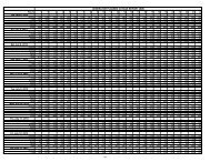
transmission zones and major transmission interfaces. Operating security limits for these interfaces are<br />
also included in Figure 3.3.1 as well as in Table 3.3. The interface limits are used to ensure system and/or<br />
plant stability, acceptable pre-contingency and post-contingency voltage levels, and/or acceptable<br />
thermal loading levels.<br />
Detailed information on interface definitions and limits can be found in <strong>IESO</strong> <strong>System</strong> Control Orders<br />
(SCOs). The release of SCO limit related information to market participants will be considered by the<br />
<strong>IESO</strong> on a need to know and case by case basis. Requests for further information should be directed to the<br />
<strong>IESO</strong> Customer Relations.<br />
3.1 Interface Definitions<br />
Interfaces are defined by grouping one or more lines for the purpose of measuring their combined flow<br />
and enforcing a power flow limit or, as it is more commonly called, an interface limit. Interface limits are<br />
directional and interfaces may have limits imposed in one or both directions.<br />
3.2 Interface Characteristics<br />
The EWTE/EWTW Interface<br />
The East-West Transfer East (EWTE) and East-West Transfer West (EWTW) flows are functionally related<br />
to the power flows between <strong>Ontario</strong> and Manitoba, and <strong>Ontario</strong> and Minnesota. In this relationship, the<br />
<strong>Ontario</strong> – Manitoba and <strong>Ontario</strong> – Minnesota flows can be generally thought of as the independent<br />
variables as they are under phase angle regulator control and can be adjusted to permit increased EWTE<br />
or EWTW flows.<br />
The maximum limits on the East-West tie are 325 MW to the east and 350 MW to the west. The EWTE and<br />
EWTW interfaces are constrained by voltage and stability limitations. A sample of historical flow<br />
distribution on the East West Interface is shown in Figure 3.3.2.<br />
The FN/FS Interface<br />
The Flow South (FS) limit is 1,550 MW and the Flow North (FN) limit is 1,900 MW. The Flow North and<br />
Flow South interfaces are constrained by voltage and stability limits respectively. A sample of historical<br />
flow distribution on the FN/FS interface is shown in Figure 3.3.2.<br />
The CLAN/CLAS Interface<br />
The Claireville North (CLAN) limit is 2,000 MW and the Claireville South (CLAS) limit is 1,000 MW.<br />
These limits have been defined to determine the boundary conditions for which the other system limits,<br />
in particular FABCW, are valid. A sample of historical flow distribution on the CLAN/CLAS interface is<br />
shown in Figure 3.3.2.<br />
<strong>November</strong> 23, <strong>2012</strong> Public Page 5