Linac2 - 50th anniversary of the CERN Proton Synchrotron
Linac2 - 50th anniversary of the CERN Proton Synchrotron
Linac2 - 50th anniversary of the CERN Proton Synchrotron

Create successful ePaper yourself
Turn your PDF publications into a flip-book with our unique Google optimized e-Paper software.
<strong>Linac2</strong><br />
1 Introduction<br />
The commissioning <strong>of</strong> <strong>the</strong> PS Booster (PSB) in 1972 shed light on <strong>the</strong> inherent limitations <strong>of</strong> Linac1<br />
as injector for <strong>the</strong> newly built synchrotron. Whereas injection from Linac1 to <strong>the</strong> PS was single-turn,<br />
<strong>the</strong> multi-turn injection introduced with <strong>the</strong> PSB had been designed for long linac pulses, up to 100 s,<br />
and high beam current, 100 mA. Although <strong>the</strong> Linac1 upgrade program launched in parallel with <strong>the</strong><br />
construction <strong>of</strong> <strong>the</strong> PSB succeeded in increasing <strong>the</strong> pulse length to 80 s and <strong>the</strong> beam current to<br />
50 mA, at <strong>the</strong> limit <strong>of</strong> what achievable by <strong>the</strong> Linac1 RF and focusing systems, <strong>the</strong>se values were still<br />
far from what <strong>the</strong> PSB was ready to accept. Moreover, because <strong>of</strong> <strong>the</strong>ir relatively old design <strong>the</strong><br />
vacuum and RF systems <strong>of</strong> Linac1 required a lot <strong>of</strong> attention and were a continuous cause <strong>of</strong> beam<br />
down time. The impressive progress in linac and vacuum technology realized in <strong>the</strong> 50’s and 60’s<br />
suggested that a new linac could have improved not only <strong>the</strong> performance but also <strong>the</strong> availability <strong>of</strong><br />
<strong>the</strong> PSB and PS injector [1].<br />
The decision to build a new linac injector, at <strong>the</strong> 50 MeV energy <strong>of</strong> <strong>the</strong> PSB injection, was<br />
<strong>the</strong>refore taken in October 1973. The design parameters were chosen in order to comfortably exceed<br />
<strong>the</strong> nominal PSB requirements, providing a safety margin during operation and for future upgrades.<br />
Beam current was specified as variable between 50 and 150 mA, for a maximum pulse length <strong>of</strong><br />
200 s. The design repetition frequency <strong>of</strong> 2 Hz was also intended to accommodate for future<br />
upgrades <strong>of</strong> PSB and PS from <strong>the</strong> standard 1.1 Hz. The decision was taken to install <strong>the</strong> new linac in a<br />
new building parallel to <strong>the</strong> Linac1 location instead that in <strong>the</strong> Linac1 tunnel, in order to avoid a long<br />
shut-down for installation and commissioning and to have Linac1 available as a back-up during <strong>the</strong><br />
first years <strong>of</strong> operation <strong>of</strong> <strong>Linac2</strong>.<br />
Construction <strong>of</strong> <strong>the</strong> “new linac”, lately called “<strong>Linac2</strong>”, started in December 1973, and <strong>the</strong> first<br />
50 MeV beam was obtained on 6 September 1978. Only a month later <strong>the</strong> design current was reached<br />
and <strong>the</strong> first injection tests in <strong>the</strong> PSB started. Routine operation for <strong>the</strong> PSB started soon after, in<br />
December 1978. As proudly announced at <strong>the</strong> time, <strong>Linac2</strong> was completed “on budget and on<br />
schedule”, for an overall cost <strong>of</strong> 23 MCHF <strong>of</strong> <strong>the</strong> time [2].<br />
2 Machine layout<br />
The proton beam is generated by a duoplasmatron ion source, which can provide a current <strong>of</strong> up to<br />
300 mA. In <strong>the</strong> original configuration, a Cockcr<strong>of</strong>t-Walton generator at 750 kV located in shielded<br />
room separated from <strong>the</strong> accelerator hall (Fig. 1) provided <strong>the</strong> pre-acceleration to <strong>the</strong> entrance <strong>of</strong> <strong>the</strong><br />
Low Energy Beam Transport (LEBT). The 5.66 m long LEBT contained 18 quadrupoles, a complete<br />
emittance measurement device toge<strong>the</strong>r with o<strong>the</strong>r diagnostics, and a bunching system made <strong>of</strong> three<br />
RF cavities, two at <strong>the</strong> basic frequency <strong>of</strong> 202.56 MHz and one at double harmonic.<br />
The main accelerator is a Drift Tube Linac <strong>of</strong> standard Alvarez design, presenting many<br />
improvements with respect to <strong>the</strong> Linac1 design. The three accelerating tanks, accelerating <strong>the</strong> beam<br />
up to 10.3, 30.5 and 50 MeV respectively, have in common <strong>the</strong> frequency 202.56 MHz and <strong>the</strong><br />
vacuum envelope. The drift tubes are suspended from a girder; <strong>the</strong>y are aligned externally and<br />
successively introduced into <strong>the</strong> tanks. A mechanical positioning system on <strong>the</strong> outside <strong>of</strong> <strong>the</strong> girder<br />
toge<strong>the</strong>r with a bellow on <strong>the</strong> inside allows positioning <strong>of</strong> <strong>the</strong> drift tubes with <strong>the</strong> required precision.<br />
The tanks are made in mild steel, with a copper foil clad to <strong>the</strong> inside. Vacuum and RF tightness are<br />
provided by aluminium wire joints. Post-couplers provide stabilization <strong>of</strong> <strong>the</strong> RF field against<br />
mechanical imperfections. The three tanks have a total length <strong>of</strong> 33.3 m [3, 4].<br />
1
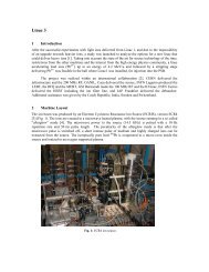
Fig. 1: <strong>Linac2</strong> 750 kV Cockcr<strong>of</strong>t-Walton, source and accelerating column.<br />
Fig. 2: <strong>Linac2</strong> tanks.<br />
Beam optics requirements for <strong>the</strong> new linac were particularly demanding because <strong>of</strong> <strong>the</strong> high<br />
space charge forces related to <strong>the</strong> 150 mA current, in particular in <strong>the</strong> LEBT and in <strong>the</strong> first Alvarez<br />
tank. Focusing is provided by pulsed electromagnetic quadrupoles placed inside <strong>the</strong> drift tubes and in<br />
<strong>the</strong> low and high-energy transport lines. A careful 6-dimensional emittance matching between <strong>the</strong><br />
different linac sections was achieved thanks to an extensive use <strong>of</strong> modern beam simulation codes.<br />
Because <strong>of</strong> <strong>the</strong> strong space charge, a transverse emittance increases by a factor 2.5 was measured<br />
2
inside <strong>the</strong> linac; however, <strong>the</strong> output emittance <strong>of</strong> 15 mm mrad (90% <strong>of</strong> <strong>the</strong> beam) is still a factor <strong>of</strong><br />
2 smaller than <strong>the</strong> PSB acceptance [5, 2].<br />
The RF system incorporated as main high-power stages an improved version <strong>of</strong> <strong>the</strong> Linac1<br />
units, with larger diameters in order to safely deliver more RF power, and improved insulators,<br />
neutralization and electronics. The RF tube was <strong>the</strong> same triode already used for most <strong>of</strong> <strong>the</strong> Linac1<br />
chains, <strong>the</strong> TH170R triode. In this configuration, <strong>the</strong> final amplifiers used for <strong>the</strong> linac tanks were able<br />
to reach a peak power <strong>of</strong> 2.5 MW. Rigid coaxial lines equipped with motorised trombones <strong>the</strong>n<br />
transport this power to <strong>the</strong> cavities, through an adjustable coupling loop designed to cope with a large<br />
range <strong>of</strong> beam currents. New low and medium-power amplifiers were developed as driving stages for<br />
<strong>the</strong> <strong>Linac2</strong> amplifier chains, allowing a modular construction <strong>of</strong> <strong>the</strong> different RF chains covering as<br />
well <strong>the</strong> buncher and debuncher amplifiers. The 40 kV anode supply for <strong>the</strong> final stages is provided by<br />
a large PFN circuit. The important beam loading due to <strong>the</strong> high linac current could be mastered<br />
thanks to a newly developed fast feedback electronics, which can provide up to 1% and 1° stability in<br />
voltage and phase in <strong>the</strong> tanks, respectively [6].<br />
At <strong>the</strong> exit <strong>of</strong> <strong>the</strong> accelerating tank, a line transports <strong>the</strong> beam up to <strong>the</strong> connection point with<br />
<strong>the</strong> Linac1 to PSB line. Initially, <strong>the</strong> line was equipped with three debunching cavities (one at double<br />
harmonic), later reduced to one because <strong>of</strong> <strong>the</strong> larger than foreseen longitudinal emittance. Singlepulse<br />
transverse and longitudinal emittance measurement lines were installed immediately at <strong>the</strong> exit<br />
<strong>of</strong> <strong>the</strong> linac, to complement <strong>the</strong> existing “old lines” at <strong>the</strong> PSB entrance. A full longitudinal emittance<br />
measurement could be performed using a dedicated bunch rotating cavity in <strong>the</strong> measurement line.<br />
3 Improvements<br />
A major improvement to <strong>Linac2</strong> was <strong>the</strong> replacement <strong>of</strong> <strong>the</strong> 750 kV Cockcr<strong>of</strong>t-Walton and <strong>of</strong> <strong>the</strong> old<br />
LEBT with a new Radio Frequency Quadrupole (RFQ) toge<strong>the</strong>r with a new source and new low and<br />
medium-energy beam transports, which took place during <strong>the</strong> 1992/93 shut-down.<br />
After <strong>the</strong> successful construction <strong>of</strong> a prototype RFQ for Linac1, <strong>the</strong> development <strong>of</strong> a highintensity<br />
RFQ for <strong>Linac2</strong>, capable <strong>of</strong> delivering to <strong>the</strong> Alvarez DTL a current <strong>of</strong> 200 mA, started<br />
already in 1984. A first high-current RFQ was commissioned on a test stand in 1989, and following<br />
this successful test <strong>the</strong> replacement <strong>of</strong> <strong>the</strong> <strong>Linac2</strong> pre-injector was <strong>of</strong>ficially approved in 1990 [7]. The<br />
main motivation for <strong>the</strong> higher current was related to <strong>the</strong> preparation <strong>of</strong> <strong>the</strong> <strong>CERN</strong> injectors for <strong>the</strong><br />
LHC that was starting in <strong>the</strong>se years. It was clear that LHC would require unprecedented beam<br />
brightness (current over emittance) from <strong>the</strong> injector chain, and one <strong>of</strong> <strong>the</strong> options considered was to<br />
go to single-turn injection into <strong>the</strong> PSB <strong>of</strong> a high-current linac beam, in order to minimise emittance<br />
growth. This in turn required <strong>the</strong> highest achievable current from <strong>the</strong> linac; simulations showed that in<br />
spite <strong>of</strong> <strong>the</strong> fact that <strong>the</strong> 200 mA beam from <strong>the</strong> RFQ was strongly mismatched longitudinally in <strong>the</strong><br />
first DTL tank which had been designed for 150 mA, a maximum current <strong>of</strong> 180 mA (within <strong>the</strong><br />
required emittances) was achievable at <strong>the</strong> exit <strong>of</strong> <strong>the</strong> linac. Of course, ano<strong>the</strong>r motivation for <strong>the</strong><br />
replacement was <strong>the</strong> simpler operation and maintenance with <strong>the</strong> smaller RFQ as compared to <strong>the</strong><br />
large Cockcr<strong>of</strong>t-Walton installation.<br />
Construction <strong>of</strong> <strong>the</strong> new RFQ started soon after approval, and <strong>the</strong> new system, called RFQ2,<br />
was installed at <strong>Linac2</strong> at <strong>the</strong> place <strong>of</strong> <strong>the</strong> old LEBT during <strong>the</strong> normal shut-down 1992/93.<br />
Commissioning <strong>of</strong> <strong>the</strong> RFQ2 with <strong>Linac2</strong> took few weeks, and <strong>the</strong> 1993 physics run started with <strong>the</strong><br />
new RFQ injector.<br />
The RFQ2 system consists <strong>of</strong> a new duoplasmatron proton source with a 90 kV extraction,<br />
followed by a short 2-solenoid LEBT <strong>of</strong> less than one meter [8]. The 4-vane RFQ (RFQ2) <strong>of</strong> 1.8 m<br />
length was entirely built at <strong>CERN</strong> and operates at <strong>the</strong> record voltage <strong>of</strong> 178 kV, corresponding to 2.4<br />
times <strong>the</strong> Kilpatrick limit. The high vane voltage is required by <strong>the</strong> large space charge <strong>of</strong> <strong>the</strong> 200 mA<br />
3
eam, so far <strong>the</strong> highest intensity reached by an operational RFQ. Longitudinal matching to <strong>the</strong><br />
Alvarez DTL is performed by two bunching cavities. Fig. 3 shows <strong>the</strong> RFQ as installed in front <strong>of</strong> <strong>the</strong><br />
<strong>Linac2</strong> tanks.<br />
Fig. 3: RFQ2 and <strong>Linac2</strong> tanks.<br />
During <strong>the</strong> first years after installation, <strong>the</strong> RFQ was operated at voltages slightly below<br />
nominal in order to limit RF breakdowns to levels compatible with <strong>the</strong> reliability required for <strong>the</strong><br />
<strong>CERN</strong> injector. This in turn limited <strong>the</strong> beam current from <strong>the</strong> RFQ to values around 180 mA. The<br />
progressive upgrade and cleaning <strong>of</strong> <strong>the</strong> vacuum system allowed reaching <strong>the</strong> design voltage a few<br />
years after installation, with <strong>the</strong> RFQ delivering beam currents in excess <strong>of</strong> 200 mA, which correspond<br />
to currents in excess <strong>of</strong> 180 mA at <strong>the</strong> exit <strong>of</strong> <strong>the</strong> linac.<br />
O<strong>the</strong>r improvements to <strong>Linac2</strong> after construction were mainly aimed at keeping <strong>the</strong> required<br />
reliability and to adapt to <strong>the</strong> evolving technologies. These included <strong>the</strong> commissioning <strong>of</strong> a new<br />
control system in 1993, <strong>the</strong> installation <strong>of</strong> new low-power solid state amplifiers and <strong>the</strong> replacement <strong>of</strong><br />
<strong>the</strong> interlocks and <strong>of</strong> <strong>the</strong> electronics <strong>of</strong> <strong>the</strong> high-power amplifiers on <strong>the</strong> RF systems.<br />
4 Conclusions<br />
It was <strong>the</strong> rapid progress in linac technology that made possible <strong>the</strong> replacement <strong>of</strong> Linac1 after 20<br />
years <strong>of</strong> operation with <strong>the</strong> new <strong>Linac2</strong>, providing a factor 2 increase in both current and pulse length,<br />
with <strong>the</strong> additional advantages <strong>of</strong> increased reliability and reduced maintenance.<br />
In <strong>the</strong> same way <strong>Linac2</strong> has been now operating smoothly and reliably for more than 30 years,<br />
but now shows similar limitations to those that led to <strong>the</strong> replacement <strong>of</strong> Linac1. On one hand, <strong>the</strong><br />
exploration <strong>of</strong> possible options for an LHC luminosity upgrade indicates that <strong>the</strong> first bottleneck for<br />
achieving a higher intensity in <strong>the</strong> PS complex is <strong>the</strong> PSB injection, where <strong>the</strong> space charge tune shift<br />
at 50 MeV energy limits <strong>the</strong> total intensity. The only way to go beyond this limitation is by increasing<br />
<strong>the</strong> linac energy, which in turns requires <strong>the</strong> construction <strong>of</strong> a new linac, an appreciable energy<br />
increase <strong>of</strong> <strong>Linac2</strong> being prevented by <strong>the</strong> lack <strong>of</strong> space at <strong>the</strong> end <strong>of</strong> <strong>the</strong> linac. On <strong>the</strong> o<strong>the</strong>r hand, over<br />
<strong>the</strong> last years <strong>Linac2</strong> has developed serious vacuum problems due to its now “old-fashioned”<br />
construction technology, which constitute a serious threat for operation. Moreover, procurements <strong>of</strong><br />
4
<strong>the</strong> RF tubes, whose design dates basically to Linac1, is becoming more and more difficult, and <strong>the</strong>re<br />
are concerns that <strong>the</strong>y could not be available in <strong>the</strong> future.<br />
These considerations suggested that <strong>the</strong> time has come for <strong>the</strong> replacement <strong>of</strong> <strong>Linac2</strong> with a<br />
new linac, which would also pr<strong>of</strong>it <strong>of</strong> recent advances in linac technology as acceleration <strong>of</strong> lowcurrent<br />
long-pulse H- beams, chopping at low energy for minimum beam loss, modern beam dynamics<br />
design. Considering all <strong>the</strong>se arguments, <strong>the</strong> <strong>CERN</strong> management has approved in June 2007 <strong>the</strong><br />
construction <strong>of</strong> <strong>the</strong> 160 MeV Linac4, which will be placed in a new building, parallel to <strong>the</strong> present<br />
<strong>Linac2</strong> location. The project has started in 2008, and connection <strong>of</strong> <strong>the</strong> new linac to <strong>the</strong> PSB is<br />
foreseen for 2015.<br />
References<br />
[1] D.J. Warner (ed.), Project Study for a new 50 MeV Linear Accelerator for <strong>the</strong> C.P.S.,<br />
<strong>CERN</strong>/MPS/LINP 73-1.<br />
[2] E. Boltezar, H. Haseroth, W. Pirkl, G. Plass, T. Sherwood, U. Tallgren, P. Tetu, D. Warner, M.<br />
Weiss, The new <strong>CERN</strong> 50-MeV Linac, 1979 Linear Accelerator Conference.<br />
[3] D. Warner, Accelerating Structures <strong>of</strong> <strong>the</strong> <strong>CERN</strong> new 50 MeV Linac, 1979 Linear Accelerator<br />
Conference.<br />
[4] E. Boltezar, Mechanical Design <strong>of</strong> <strong>CERN</strong> New Linac Accelerating Structures, 1979 Linear<br />
Accelerator Conference.<br />
[5] D.J. Warner and M. Weiss, Beam Optics in <strong>the</strong> <strong>CERN</strong> new 50 MeV Linac, 1979 Linear<br />
Accelerator Conference.<br />
[6] J. Cuperus, F. James and W. Pirkl, The RF System <strong>of</strong> <strong>the</strong> <strong>CERN</strong> “New Linac”, 1979 Linear<br />
Accelerator Conference.<br />
[7] J.L. Vallet, M. Vretenar and M. Weiss, Field Adjustment, Tuning, and Beam Analysis <strong>of</strong> <strong>the</strong><br />
High-Intensity <strong>CERN</strong> RFQ, <strong>CERN</strong>-PS-90-19-HI, 1990 EPAC Conference.<br />
[8] M. Weiss, The RFQ2 complex: <strong>the</strong> future injector to <strong>CERN</strong> Linac 2, <strong>CERN</strong>-PS-92-34-HI, 1992<br />
EPAC Conference.<br />
5