The PS in the LEP injector chain - 50th anniversary of the CERN ...
The PS in the LEP injector chain - 50th anniversary of the CERN ...
The PS in the LEP injector chain - 50th anniversary of the CERN ...

Create successful ePaper yourself
Turn your PDF publications into a flip-book with our unique Google optimized e-Paper software.
<strong>The</strong> <strong>PS</strong> <strong>in</strong> <strong>the</strong> <strong>LEP</strong> <strong>in</strong>jector cha<strong>in</strong><br />
1 Brief overview <strong>of</strong> <strong>the</strong> cha<strong>in</strong> <strong>of</strong> <strong>LEP</strong> <strong>in</strong>jectors<br />
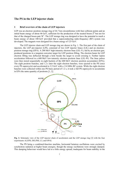
<strong>LEP</strong> was an electron–positron storage r<strong>in</strong>g <strong>of</strong> 26.7 km circumference with four collision po<strong>in</strong>ts and an<br />
<strong>in</strong>itial beam energy <strong>of</strong> about 46 GeV, sufficient for <strong>the</strong> production <strong>of</strong> <strong>the</strong> neutral boson Z 0 but not for<br />
that <strong>of</strong> <strong>the</strong> charged boson pair W ± . <strong>The</strong> <strong>LEP</strong> storage r<strong>in</strong>g was designed to have <strong>the</strong> potential to reach a<br />
beam energy <strong>of</strong> about 100 GeV provided that a superconduct<strong>in</strong>g radio-frequency (RF) system was<br />
developed. <strong>The</strong> magnets were designed for a beam energy <strong>of</strong> 125 GeV.<br />
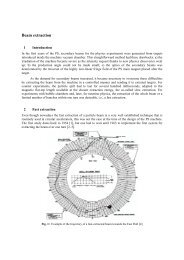
<strong>The</strong> <strong>LEP</strong> <strong>in</strong>jector cha<strong>in</strong> and <strong>LEP</strong> storage r<strong>in</strong>g are shown <strong>in</strong> Fig. 1. <strong>The</strong> first part <strong>of</strong> <strong>the</strong> cha<strong>in</strong> <strong>of</strong><br />
<strong>in</strong>jectors, <strong>the</strong> <strong>LEP</strong> pre-<strong>in</strong>jector (LPI), consisted <strong>of</strong> two <strong>LEP</strong> <strong>in</strong>jector l<strong>in</strong>acs (LIL) and an electron–<br />
positron storage r<strong>in</strong>g (EPA). A 200 MeV high-<strong>in</strong>tensity electron l<strong>in</strong>ac (LIL-V), fed by an electron gun,<br />
produced positrons <strong>in</strong> a tungsten converter target for <strong>LEP</strong> positron fill<strong>in</strong>g. <strong>The</strong> electron beam for <strong>LEP</strong><br />
electron fill<strong>in</strong>g was deflected through a hole beside <strong>the</strong> target to avoid cross<strong>in</strong>g it. Fur<strong>the</strong>r lepton<br />
acceleration followed <strong>in</strong> a 600 MeV low-<strong>in</strong>tensity electron–positron l<strong>in</strong>ac (LIL-W). <strong>The</strong> l<strong>in</strong>ac pulses<br />
were <strong>the</strong>n stored sequentially <strong>in</strong> eight buckets <strong>of</strong> <strong>the</strong> 600 MeV electron–positron accumulator (EPA).<br />
<strong>The</strong> eight positron bunches, and 1.2 s later <strong>the</strong> eight electron bunches, were ejected to <strong>the</strong> <strong>PS</strong> (once<br />
every <strong>PS</strong> supercycle) and accelerated to 3.5 GeV with a 114 MHz RF system. While <strong>the</strong> eight electron<br />
bunches were collected with<strong>in</strong> one <strong>PS</strong> basic period <strong>of</strong> 1.2 s, it took a full <strong>PS</strong> supercycle to accumulate<br />
<strong>in</strong> EPA <strong>the</strong> same quantity <strong>of</strong> positrons [1, 2].<br />
Fig. 1: Schematic view <strong>of</strong> <strong>the</strong> <strong>LEP</strong> <strong>in</strong>jector cha<strong>in</strong> <strong>of</strong> accelerators and <strong>the</strong> <strong>LEP</strong> storage r<strong>in</strong>g [3] with <strong>the</strong> four<br />
experiments A<strong>LEP</strong>H, DELPHI, L3, and OPAL<br />
<strong>The</strong> <strong>PS</strong> be<strong>in</strong>g a comb<strong>in</strong>ed-function mach<strong>in</strong>e, horizontal betatron oscillations were excited by<br />
synchrotron radiation at higher beam energies, though <strong>the</strong> energy oscillations were strongly damped.<br />
This damp<strong>in</strong>g behaviour would have led to a little energy spread, <strong>in</strong>adequate for beam stability <strong>in</strong> <strong>the</strong><br />
1
<strong>PS</strong> and for S<strong>PS</strong> <strong>in</strong>jection. To modify and control <strong>the</strong> damp<strong>in</strong>g partition, Rob<strong>in</strong>son wigglers had to be<br />
<strong>in</strong>stalled <strong>in</strong> <strong>the</strong> <strong>PS</strong>. S<strong>in</strong>ce <strong>the</strong> electron–positron emittances were smaller than <strong>the</strong> proton emittances, <strong>the</strong><br />
leptons could be accepted by <strong>the</strong> S<strong>PS</strong> at a fairly low energy <strong>of</strong> 3.5 GeV. However, to prevent<br />
<strong>in</strong>stabilities and beam losses, <strong>the</strong> total charge accelerated per pulse had to be spread over many<br />
bunches. This was <strong>the</strong> reason for choos<strong>in</strong>g eight bunches throughout <strong>the</strong> <strong>in</strong>jector cha<strong>in</strong> as <strong>the</strong> basic<br />
mode <strong>of</strong> operation.<br />
Next, <strong>the</strong> eight positron bunches were transferred to <strong>the</strong> S<strong>PS</strong> <strong>in</strong> two batches <strong>of</strong> four bunches<br />
(spaced by 30 ms) via <strong>the</strong> exist<strong>in</strong>g proton beam l<strong>in</strong>e TT10, and <strong>the</strong> eight electron bunches were<br />
similarly sent <strong>the</strong> S<strong>PS</strong> <strong>in</strong> two batches <strong>of</strong> four bunches through <strong>the</strong> past antiproton beam l<strong>in</strong>e TT70. <strong>The</strong><br />
leptons were orig<strong>in</strong>ally accelerated to 20 GeV <strong>in</strong> <strong>the</strong> S<strong>PS</strong> with an extra 200 MHz RF system consist<strong>in</strong>g<br />
<strong>of</strong> 32 s<strong>in</strong>gle-cell cavities and, after extraction <strong>the</strong> S<strong>PS</strong>, <strong>the</strong>y were sent to <strong>LEP</strong> via two new transfer<br />
l<strong>in</strong>es.<br />
<strong>The</strong> lepton beams were <strong>in</strong>jected <strong>in</strong> <strong>the</strong> arcs <strong>of</strong> <strong>LEP</strong>, where <strong>the</strong> dispersion function was non-zero.<br />
<strong>The</strong> circulat<strong>in</strong>g beam was brought close to <strong>the</strong> septum by means <strong>of</strong> a closed-orbit bump so that <strong>the</strong><br />
<strong>in</strong>com<strong>in</strong>g beam <strong>the</strong>n followed an orbit similar to and near to that <strong>of</strong> <strong>the</strong> circulat<strong>in</strong>g beam. So, <strong>the</strong><br />
<strong>in</strong>jected bunch could be stacked <strong>in</strong> ei<strong>the</strong>r betatron phase space (large-amplitude betatron oscillations<br />
about <strong>the</strong> central orbit <strong>in</strong>tegrat<strong>in</strong>g <strong>the</strong> stored beam density after synchrotron radiation damp<strong>in</strong>g) or<br />
synchrotron phase space (large-amplitude synchrotron oscillations about an <strong>of</strong>f-momentum orbit,<br />
reach<strong>in</strong>g <strong>the</strong> stored beam density after damp<strong>in</strong>g, as <strong>the</strong> dispersion function was non-zero at <strong>in</strong>jection<br />
and <strong>the</strong> <strong>in</strong>com<strong>in</strong>g lepton energy was a bit lower than <strong>the</strong> tuned <strong>LEP</strong> energy) next to <strong>the</strong> already<br />
circulat<strong>in</strong>g bunch <strong>of</strong> <strong>LEP</strong>. <strong>The</strong> same <strong>in</strong>jection equipment was used for both betatron and synchrotron<br />
phase space stack<strong>in</strong>g schemes, <strong>the</strong> preference among <strong>the</strong> two depend<strong>in</strong>g on <strong>the</strong> <strong>LEP</strong> operation mode.<br />
Quite wide-rang<strong>in</strong>g modifications had to be made to use <strong>the</strong> <strong>PS</strong> as a 3.5 GeV electron–positron<br />
synchrotron. Almost all <strong>the</strong> exist<strong>in</strong>g equipment <strong>of</strong> <strong>the</strong> <strong>PS</strong> mach<strong>in</strong>e was compatible with <strong>the</strong><br />
acceleration <strong>of</strong> electrons and positrons. However, <strong>the</strong> vacuum chamber was entirely changed; electron<br />
and positron transfer l<strong>in</strong>es from EPA to <strong>PS</strong> and <strong>in</strong>jections <strong>in</strong>to <strong>the</strong> <strong>PS</strong> were added. New 114 MHz RF<br />
cavities, Rob<strong>in</strong>son wiggler magnets, and some <strong>in</strong>strumentation were added too. <strong>The</strong> new <strong>in</strong>jection<br />
system was <strong>in</strong>stalled without compromis<strong>in</strong>g <strong>the</strong> performance with proton beams. <strong>The</strong> extraction<br />
channels were <strong>the</strong> same as for proton–antiproton operation. S<strong>in</strong>ce <strong>the</strong> <strong>PS</strong> is a comb<strong>in</strong>ed-function lattice<br />
synchrotron and has a long acceleration cycle, <strong>the</strong> implementation <strong>of</strong> Rob<strong>in</strong>son wigglers to ensure <strong>the</strong><br />
stability <strong>of</strong> <strong>the</strong> beams was essential. <strong>The</strong> wigglers also helped to match <strong>the</strong> longitud<strong>in</strong>al bunch size to<br />
<strong>the</strong> S<strong>PS</strong>.<br />
In 1986 leptons were <strong>in</strong>jected and accumulated <strong>in</strong> <strong>the</strong> EPA at 500 MeV <strong>in</strong>stead <strong>of</strong> 600 MeV as<br />
<strong>in</strong>itially planned. S<strong>in</strong>ce <strong>the</strong>n, 500 MeV rema<strong>in</strong>ed <strong>the</strong> nom<strong>in</strong>al lepton energy <strong>in</strong> EPA. First <strong>in</strong>jection <strong>in</strong><br />
<strong>the</strong> <strong>PS</strong> <strong>of</strong> electrons at 500 MeV and acceleration was achieved <strong>in</strong> 1986. By 1987 electron and positron<br />
beams were ready.<br />
2 Operat<strong>in</strong>g modes <strong>of</strong> <strong>the</strong> <strong>PS</strong> and S<strong>PS</strong> <strong>in</strong>jectors<br />
In <strong>the</strong> early years for <strong>the</strong> basic mode <strong>of</strong> operation <strong>the</strong> electrons or positrons were accelerated <strong>in</strong> <strong>the</strong><br />
dead-time <strong>of</strong> <strong>the</strong> S<strong>PS</strong>; but <strong>in</strong> place <strong>of</strong> one acceleration cycle, four 1.2 s lepton magnetic cycles were<br />
<strong>in</strong>serted between <strong>the</strong> proton cycles to decrease <strong>the</strong> <strong>in</strong>tensity <strong>of</strong> <strong>the</strong> lepton beams <strong>in</strong> <strong>the</strong> <strong>in</strong>jectors for<br />
beam stability reasons. Positrons were accelerated <strong>in</strong> <strong>the</strong> first two cycles and electrons <strong>in</strong> <strong>the</strong> second<br />
two, which led to <strong>the</strong> <strong>PS</strong> and S<strong>PS</strong> supercycle pattern {p e + e + e - e - }. Both <strong>LEP</strong> beams consisted <strong>of</strong> four<br />
bunches. Figure 2 shows <strong>the</strong> magnet supercycle <strong>of</strong> <strong>the</strong> S<strong>PS</strong> and <strong>PS</strong>, and <strong>the</strong> total beam <strong>in</strong>tensity <strong>in</strong> <strong>the</strong><br />
EPA. <strong>PS</strong> and S<strong>PS</strong> supercycles were made <strong>of</strong> various magnetic cycles, one or several cycles be<strong>in</strong>g<br />
allocated to each user [4].<br />
With<strong>in</strong> a S<strong>PS</strong> 14.4 s supercycle time period, <strong>the</strong> positrons were accumulated <strong>in</strong> <strong>the</strong> EPA dur<strong>in</strong>g<br />
<strong>the</strong> quite long S<strong>PS</strong> proton cycles due to <strong>the</strong> low positron <strong>in</strong>tensity <strong>of</strong> <strong>the</strong> l<strong>in</strong>ac (LIL-W). <strong>The</strong> l<strong>in</strong>ac<br />
2
operated with a repetition frequency <strong>of</strong> 100 Hz, and each pulse was put one at a time <strong>in</strong>to ano<strong>the</strong>r one<br />
<strong>of</strong> <strong>the</strong> eight EPA stockpil<strong>in</strong>g buckets by stack<strong>in</strong>g <strong>the</strong> pulse <strong>in</strong> betatron phase space close to <strong>the</strong> stored<br />
bunch (<strong>the</strong> elapsed time between two <strong>in</strong>jections <strong>in</strong>to <strong>the</strong> same bucket was 80 ms). Hence, after <strong>the</strong><br />
required beam <strong>in</strong>tensity was reached, each <strong>of</strong> <strong>the</strong> eight positron bunches was moved onto a th<strong>in</strong><br />
electrostatic septum which cut <strong>in</strong> half <strong>the</strong> bunch <strong>in</strong> betatron phase space and ejected one half to <strong>the</strong> <strong>PS</strong><br />
on <strong>the</strong> first positron cycle. <strong>The</strong> rema<strong>in</strong><strong>in</strong>g eight halves stayed <strong>in</strong> EPA wait<strong>in</strong>g for <strong>the</strong> second positron<br />
cycle to be transferred to <strong>the</strong> <strong>PS</strong>. <strong>The</strong> eight bunches <strong>in</strong>jected <strong>in</strong>to <strong>the</strong> <strong>PS</strong> were <strong>the</strong>n accelerated to<br />
3.5 GeV and ejected to <strong>the</strong> S<strong>PS</strong>, accelerated to 20 GeV and sent to <strong>LEP</strong>. Once <strong>the</strong> positrons were<br />
extracted from EPA <strong>the</strong> l<strong>in</strong>ac began to <strong>in</strong>ject electrons and filled up <strong>the</strong> eight EPA bunches to an<br />
<strong>in</strong>tensity equal to half that <strong>of</strong> <strong>the</strong> positrons. <strong>The</strong> eight electron bunches were <strong>the</strong>n transferred through<br />
<strong>the</strong> <strong>PS</strong> and S<strong>PS</strong> to <strong>LEP</strong> like <strong>the</strong> positrons. After <strong>the</strong> second electron cycle, <strong>the</strong> l<strong>in</strong>acs resumed positron<br />
<strong>in</strong>jection <strong>in</strong>to <strong>the</strong> EPA. All circular <strong>in</strong>jector accelerators ran with eight bunches to lessen <strong>the</strong> charge<br />
per bunch.<br />
Fig. 2: <strong>The</strong> 14.4 s <strong>PS</strong> and S<strong>PS</strong> supercycles and <strong>the</strong> EPA total beam <strong>in</strong>tensity. Positrons and electrons were<br />
accelerated on <strong>the</strong> four last consecutive 1.2 s cycles <strong>of</strong> <strong>the</strong> <strong>PS</strong> supercycle<br />
Variant operat<strong>in</strong>g mode schemes were exam<strong>in</strong>ed to cope with possible constra<strong>in</strong>ts due to <strong>the</strong><br />
stability thresholds. Had <strong>the</strong> thresholds been less favorable than expected, <strong>the</strong> <strong>PS</strong> and S<strong>PS</strong> bunch<br />
<strong>in</strong>tensity would have had to be decreased by a factor <strong>of</strong>, say, two and <strong>the</strong> number <strong>of</strong> cycles doubled.<br />
<strong>The</strong> EPA electrostatic septum would have cut <strong>the</strong> eight positron bunches such that one quarter <strong>of</strong> <strong>the</strong><br />
<strong>in</strong>itial <strong>in</strong>tensity was extracted each time. <strong>The</strong> eight bunches rema<strong>in</strong><strong>in</strong>g for <strong>the</strong> last positron cycle would<br />
have been transferred to <strong>the</strong> <strong>PS</strong> via standard extraction. <strong>The</strong> electrons would have been handled <strong>in</strong> <strong>the</strong><br />
same way as <strong>in</strong> <strong>the</strong> basic scheme, except that <strong>the</strong>re would have been four electron transfers dur<strong>in</strong>g <strong>the</strong><br />
supercycle <strong>in</strong>stead <strong>of</strong> two.<br />
Later, once <strong>the</strong> new 100 MHz RF cavities were <strong>in</strong>stalled <strong>in</strong> <strong>the</strong> S<strong>PS</strong>, allow<strong>in</strong>g <strong>the</strong> bunch<br />
<strong>in</strong>tensity to be <strong>in</strong>creased, a new mode <strong>of</strong> operation us<strong>in</strong>g only two magnetic cycles per <strong>PS</strong> supercycle<br />
was feasible, <strong>the</strong> first cycle for positron acceleration and <strong>the</strong> second for electron acceleration.<br />
3 Lepton <strong>in</strong>jection <strong>in</strong>to <strong>the</strong> <strong>PS</strong><br />
<strong>The</strong> ratio <strong>of</strong> <strong>the</strong> <strong>PS</strong> and EPA circumferences was chosen to be equal to <strong>the</strong> <strong>in</strong>teger 5, and s<strong>in</strong>ce <strong>the</strong><br />
bunches were equidistant <strong>in</strong> EPA and <strong>PS</strong> <strong>the</strong> eight EPA bunches could be <strong>in</strong>jected with<strong>in</strong> a s<strong>in</strong>gle turn<br />
<strong>of</strong> <strong>the</strong> <strong>PS</strong>. S<strong>in</strong>gle-turn <strong>in</strong>jection was desirable because it makes <strong>the</strong> beam transfer very fast so that a<br />
slowly ris<strong>in</strong>g <strong>PS</strong> magnetic field could be allowed. <strong>The</strong> design <strong>of</strong> <strong>the</strong> <strong>PS</strong> <strong>in</strong>jection channels took <strong>in</strong>to<br />
account <strong>the</strong> constra<strong>in</strong>ts imposed by <strong>the</strong> position <strong>of</strong> <strong>the</strong> EPA and <strong>the</strong> operation <strong>of</strong> <strong>the</strong> <strong>PS</strong> with proton<br />
beams. Symmetric <strong>in</strong>jection trajectories <strong>in</strong>to <strong>the</strong> <strong>PS</strong> were chosen to standardize equipment, with a<br />
large angle <strong>of</strong> <strong>in</strong>cidence <strong>of</strong> 160 mrad to reduce <strong>the</strong> magnet stray field effect. <strong>The</strong> <strong>in</strong>jection positron<br />
septum was located <strong>in</strong> straight section SS92, that <strong>of</strong> <strong>the</strong> electron septum <strong>in</strong> SS74. Enough space was<br />
left <strong>in</strong> <strong>the</strong> straight sections for <strong>the</strong> <strong>in</strong>stallation <strong>of</strong> a vertical correction dipole and a position monitor [1].<br />
3
<strong>The</strong> <strong>in</strong>jection positron kicker was located <strong>in</strong> SS94 and <strong>the</strong> electron kicker <strong>in</strong> SS72. <strong>The</strong> kicker fall-time<br />
was less than 250 ns, correspond<strong>in</strong>g to less than one eighth <strong>of</strong> <strong>the</strong> <strong>PS</strong> circumference. <strong>The</strong> kick strength<br />
(9 mrad) was strong enough that no slow <strong>in</strong>jection bump was necessary. S<strong>in</strong>gle-turn <strong>in</strong>jection was<br />
achieved through <strong>the</strong> electron (positron) <strong>in</strong>jection channel by means <strong>of</strong> a fast kicker magnet one eighth<br />
<strong>of</strong> a betatron wavelength downstream <strong>of</strong> a pulsed septum magnet. <strong>The</strong>re was no closed orbit bump <strong>in</strong><br />
<strong>the</strong> <strong>in</strong>jection area so as to avoid aperture restrictions.<br />
Chromaticity adjustments were performed with a small damp<strong>in</strong>g change at <strong>in</strong>jection us<strong>in</strong>g <strong>the</strong><br />
<strong>PS</strong> auxiliary w<strong>in</strong>d<strong>in</strong>gs. A small energy damp<strong>in</strong>g partition number change <strong>of</strong> ΔJ e = −0.5 was obta<strong>in</strong>ed<br />
through an unbalanced comb<strong>in</strong>ed-function bend<strong>in</strong>g magnet field us<strong>in</strong>g <strong>the</strong> <strong>PS</strong> auxiliary w<strong>in</strong>d<strong>in</strong>g<br />
figure-<strong>of</strong>-eight loop. <strong>The</strong> ensu<strong>in</strong>g tune change was cancelled by power<strong>in</strong>g <strong>the</strong> focus<strong>in</strong>g and defocus<strong>in</strong>g<br />
pole-face-w<strong>in</strong>d<strong>in</strong>g coils. <strong>The</strong> sextupolar component <strong>of</strong> <strong>the</strong>se coils modified <strong>the</strong> chromaticities and<br />
made <strong>the</strong>m positive <strong>in</strong> both planes, as required to avoid head–tail <strong>in</strong>stabilities.<br />
4 Emittance control <strong>of</strong> <strong>the</strong> <strong>PS</strong> lepton beams us<strong>in</strong>g a Rob<strong>in</strong>son wiggler<br />
In 1958, Rob<strong>in</strong>son <strong>of</strong> <strong>the</strong> Cambridge electron accelerator (Massachusetts) proposed that a gradient<br />
wiggler magnet be used to stabilize naturally unstable electron and positron beams <strong>in</strong> comb<strong>in</strong>edfunction<br />
mach<strong>in</strong>es. In 1986 such a method was applied <strong>in</strong> <strong>the</strong> <strong>PS</strong> so that it could serve as an<br />
accelerator <strong>in</strong> <strong>the</strong> <strong>LEP</strong> <strong>in</strong>jector cha<strong>in</strong>. A prototype wiggler magnet was designed and constructed at<br />
<strong>CERN</strong>. As predictions were confirmed by measurements carried out <strong>in</strong> <strong>the</strong> <strong>PS</strong> with electrons and <strong>in</strong><br />
<strong>the</strong> DCI (LAL, Orsay, France) with positrons to check <strong>the</strong> damp<strong>in</strong>g variations produced by this<br />
wiggler, three wigglers were <strong>in</strong>stalled <strong>in</strong> <strong>the</strong> <strong>PS</strong> as it was part <strong>of</strong> <strong>the</strong> <strong>LEP</strong> <strong>in</strong>jector cha<strong>in</strong> [5].<br />
A Rob<strong>in</strong>son gradient wiggler magnet consists <strong>of</strong> an even number <strong>of</strong> comb<strong>in</strong>ed dipole–<br />
quadrupole magnet blocks <strong>of</strong> identical pole pr<strong>of</strong>ile. <strong>The</strong> orientation <strong>of</strong> <strong>the</strong> pole pr<strong>of</strong>ile is <strong>the</strong> same <strong>in</strong><br />
all four blocks with field and gradient <strong>of</strong> alternat<strong>in</strong>g polarity. <strong>The</strong> overall beam deflection is cancelled<br />
by power<strong>in</strong>g <strong>the</strong> half <strong>of</strong> <strong>the</strong> blocks with opposite polarities. To first-order this restricts <strong>the</strong> closed-orbit<br />
perturbation and <strong>of</strong>fsets <strong>the</strong> quadrupole focus<strong>in</strong>g.<br />
<strong>The</strong> damp<strong>in</strong>g <strong>of</strong> betatron and energy oscillations is proportional to <strong>the</strong> damp<strong>in</strong>g partition<br />
numbers J x , J y , J e which can be expressed <strong>in</strong> terms <strong>of</strong> synchrotron radiation <strong>in</strong>tegrals I 2 and I 4 where D x<br />
is <strong>the</strong> dispersion function, B y <strong>the</strong> magnetic field, ρ x <strong>the</strong> curvature radius, and k x =(B y ρ x ) -1 ∂B y /∂x <strong>the</strong><br />
normalized gradient<br />
1 <br />
<br />
1 2 <br />
<br />
with (assum<strong>in</strong>g a planar r<strong>in</strong>g and wiggler sector magnets for simplicity)<br />
<br />
<br />
<br />
<br />
<br />
12 .<br />
An <strong>in</strong>dividual wiggler magnet adds a contribution ΔI 4 to I 4 and a small positive amount ΔI 2 to I 2<br />
∆ 2<br />
<br />
wiggler <br />
4<br />
<br />
Δ <br />
<br />
wiggler <br />
<br />
If <strong>the</strong> gradient wiggler is such that field and gradient are <strong>of</strong> opposite sign (i.e., B y ∂B y /dx < 0), its<br />
contribution to ΔI 4 is negative and consequently ΔJ x is positive (though ΔI 2 > 0 slightly lessens <strong>the</strong><br />
positive change <strong>of</strong> J x ) and damp<strong>in</strong>g is <strong>in</strong>creased <strong>in</strong> <strong>the</strong> horizontal plane. Hence <strong>the</strong> gradient wiggler<br />
magnet <strong>in</strong>creases <strong>the</strong> damp<strong>in</strong>g <strong>of</strong> radial betatron oscillations and decreases <strong>the</strong> damp<strong>in</strong>g <strong>of</strong> energy<br />
oscillations (J e = 2 + I 4 /I 2 ).<br />
Equilibrium transverse emittances and energy spread are reached when <strong>the</strong> mean quantum<br />
excitation rates are equal to damp<strong>in</strong>g rates<br />
.
2 <br />
for a planar r<strong>in</strong>g, where C q = 3.8319 × 10 -13 for electrons–positrons, and<br />
2 | |.<br />
<strong>The</strong> <strong>PS</strong> gradient wiggler magnet consisted <strong>of</strong> four consecutive blocks <strong>of</strong> identical pole pr<strong>of</strong>ile<br />
open to <strong>the</strong> outside <strong>of</strong> <strong>the</strong> mach<strong>in</strong>e (see Figs. 3–5), powered ei<strong>the</strong>r as a FDDF or DFFD structure. Both<br />
configurations provided <strong>the</strong> same damp<strong>in</strong>g and focus<strong>in</strong>g changes, but <strong>the</strong> former produced <strong>in</strong> <strong>the</strong><br />
wiggler a local closed-orbit bump to <strong>the</strong> outside <strong>of</strong> <strong>the</strong> mach<strong>in</strong>e whereas <strong>the</strong> latter produced a local<br />
orbit bump to <strong>the</strong> <strong>in</strong>side, <strong>the</strong> two outer blocks produc<strong>in</strong>g about <strong>the</strong> same deflection as <strong>the</strong> <strong>in</strong>ner ones.<br />
Fig. 3: Schematic representation <strong>of</strong> <strong>the</strong> four Rob<strong>in</strong>son gradient wiggler blocks<br />
Fig. 4: One <strong>of</strong> <strong>the</strong> four identical <strong>PS</strong> wiggler blocks before end shimm<strong>in</strong>g<br />
Fig. 5: A wiggler <strong>in</strong>stalled <strong>in</strong> a <strong>PS</strong> straight section<br />
<strong>The</strong> wiggler was <strong>in</strong>stalled <strong>in</strong> a straight section <strong>of</strong> <strong>the</strong> <strong>PS</strong> toge<strong>the</strong>r with a correction dipole to<br />
compensate for residual horizontal orbit distortion and with a correction quadrupole to reduce <strong>the</strong><br />
5
etatron tune changes. <strong>The</strong> wiggler polarity was such that <strong>the</strong> local closed-orbit bump <strong>in</strong> <strong>the</strong> magnet<br />
was to <strong>the</strong> outside <strong>of</strong> <strong>the</strong> <strong>PS</strong>. Closed-orbit distortion and betatron tune changes <strong>in</strong>duced by <strong>the</strong> wiggler<br />
were measured as a function <strong>of</strong> energy.<br />
<strong>The</strong> wiggler was <strong>the</strong>n transferred and <strong>in</strong>stalled, toge<strong>the</strong>r with an adapted vacuum chamber on<br />
<strong>the</strong> bottom r<strong>in</strong>g <strong>of</strong> DCI (LAL, Orsay). Its polarity was such that <strong>the</strong> local bump <strong>in</strong> <strong>the</strong> wiggler was<br />
towards <strong>the</strong> outside <strong>of</strong> <strong>the</strong> mach<strong>in</strong>e. Measurements <strong>of</strong> <strong>the</strong> bunch length (by means <strong>of</strong> <strong>the</strong> digitized<br />
signal from a PU electrode) and <strong>the</strong> horizontal pr<strong>of</strong>ile (by means <strong>of</strong> synchrotron light monitors) were<br />
carried out for various wiggler excitations. <strong>The</strong> longitud<strong>in</strong>al and horizontal partition numbers were<br />
deduced from <strong>the</strong> measurements. Figure 6 shows <strong>the</strong> effect on <strong>the</strong> horizontal beam size when <strong>the</strong><br />
wiggler is excited.<br />
Fig. 6: Horizontal positron beam pr<strong>of</strong>ile <strong>in</strong> DCI (a) without <strong>the</strong> wiggler, (b) when <strong>the</strong> wiggler was excited<br />
Measurements with a proton beam <strong>in</strong> <strong>the</strong> <strong>PS</strong> showed that <strong>the</strong> wiggler magnet behaved as<br />
expected as far as beam optics are concerned. Measurements with a positron beam <strong>in</strong> <strong>the</strong> DCI showed<br />
that damp<strong>in</strong>g changes expected were obta<strong>in</strong>ed <strong>in</strong> both <strong>the</strong> horizontal and longitud<strong>in</strong>al planes. In <strong>the</strong> <strong>PS</strong><br />
a maximum change <strong>of</strong> ΔJ x = 1.6 could be produced by such a wiggler. Follow<strong>in</strong>g <strong>the</strong>se results, three<br />
magnets <strong>of</strong> this type were <strong>in</strong>stalled <strong>in</strong> <strong>the</strong> <strong>PS</strong> <strong>in</strong> 1986 to provide <strong>the</strong> required damp<strong>in</strong>g changes and<br />
enable this mach<strong>in</strong>e to play its role <strong>in</strong> <strong>the</strong> <strong>LEP</strong> <strong>in</strong>jector cha<strong>in</strong>.<br />
Because <strong>of</strong> <strong>the</strong> comb<strong>in</strong>ed-function magnets <strong>in</strong> <strong>the</strong> <strong>PS</strong>, <strong>the</strong> longitud<strong>in</strong>al and horizontal damp<strong>in</strong>g<br />
partition numbers were J e = 4 and J x = −1, so electron acceleration was anticipated to be horizontally<br />
unstable. Thus <strong>in</strong> all three modes <strong>the</strong> damp<strong>in</strong>g partition numbers, and hence <strong>the</strong> longitud<strong>in</strong>al and<br />
horizontal beam emittances, had to be controlled by Rob<strong>in</strong>son wigglers (<strong>in</strong> particular, gett<strong>in</strong>g J x > 0<br />
was essential to ensure beam stability).<br />
5 Synchrotron radiation and vacuum<br />
<strong>The</strong> synchrotron radiation did not penetrate <strong>the</strong> wall <strong>of</strong> <strong>the</strong> <strong>PS</strong> vacuum chamber at 3.5 GeV. <strong>The</strong><br />
critical energy <strong>of</strong> <strong>the</strong> photons was only 1.4 keV, and <strong>the</strong> photons were absorbed upon travers<strong>in</strong>g a few<br />
micrometres <strong>of</strong> metal. With 8 × 10 10 particles circulat<strong>in</strong>g <strong>in</strong> <strong>the</strong> <strong>PS</strong> on <strong>the</strong> 3.5 GeV flat-top <strong>the</strong> power<br />
lost <strong>in</strong> <strong>the</strong> vacuum chamber around <strong>the</strong> bend<strong>in</strong>g magnets was about 1 Wm -1 so that no noticeable<br />
heat<strong>in</strong>g <strong>of</strong> <strong>the</strong> vacuum chamber occurred.<br />
Concern had been expressed early on about <strong>the</strong> amount <strong>of</strong> synchrotron-radiation-<strong>in</strong>duced gas<br />
desorption <strong>in</strong> <strong>the</strong> <strong>PS</strong> due to <strong>the</strong> acceleration <strong>of</strong> positrons and electrons. Extrapolations from<br />
measurements made on <strong>the</strong> DCI (LAL, Orsay) <strong>in</strong> 1984 showed that <strong>the</strong> <strong>in</strong>itial <strong>in</strong>crease <strong>in</strong> outgass<strong>in</strong>g<br />
rate due to synchrotron radiation would have been more than one order <strong>of</strong> magnitude above <strong>the</strong> actual<br />
outgass<strong>in</strong>g level with protons and what had been <strong>in</strong>itially assumed for electrons–positrons.<br />
Experimental data on <strong>the</strong> molecular yield η (number <strong>of</strong> molecules produced per <strong>in</strong>cident photon) on<br />
sta<strong>in</strong>less steel at <strong>PS</strong> conditions had been obta<strong>in</strong>ed from a test <strong>of</strong> a typical chamber <strong>in</strong> a beam l<strong>in</strong>e <strong>of</strong> <strong>the</strong><br />
DCI r<strong>in</strong>g [1].<br />
6
Results showed that from an <strong>in</strong>itial value <strong>of</strong> 10 -8 mbar, <strong>the</strong> mean pressure grew to 2 × 10 -7 mbar<br />
(1.5 × l0 -7 Torr) with four nom<strong>in</strong>al electron cycles <strong>in</strong> a 14.4 s supercycle. <strong>The</strong> lowest mean dynamic<br />
pressure dur<strong>in</strong>g a nom<strong>in</strong>al supercycle was with<strong>in</strong> a factor two to three from <strong>the</strong> maximum, ow<strong>in</strong>g to<br />
<strong>the</strong> large vacuum-system time constant and delayed outgass<strong>in</strong>g. After exposure to synchrotron light,<br />
<strong>the</strong> time to recover to with<strong>in</strong> 50% <strong>of</strong> <strong>the</strong> base pressure was <strong>of</strong> <strong>the</strong> order <strong>of</strong> one hour. <strong>The</strong> highest<br />
dynamic pressure registered <strong>in</strong> <strong>the</strong> r<strong>in</strong>g under nom<strong>in</strong>al conditions was 4 × 10 -7 mbar (3 × l0 -7 Torr).<br />
Comparison <strong>of</strong> <strong>in</strong>itial molecular yields <strong>of</strong> <strong>the</strong> EPA (η = 1.2 × 10 -5 ) and <strong>of</strong> <strong>the</strong> <strong>PS</strong> (η = 2.5 × 10 -3 )<br />
showed a noticeable difference <strong>in</strong> <strong>the</strong> surface state <strong>of</strong> <strong>the</strong>se two sta<strong>in</strong>less steel chambers, which could<br />
not be expla<strong>in</strong>ed only by <strong>the</strong> photon energy (<strong>the</strong> <strong>PS</strong> critical energy 1.4 keV at 3.5 GeV, EPA 200 eV at<br />
500 MeV). <strong>The</strong> better EPA performance was thought to be caused by <strong>the</strong> 950°C vacuum fir<strong>in</strong>g applied<br />
as <strong>the</strong> last step <strong>in</strong> <strong>the</strong> chamber preparation sequence. This had re<strong>in</strong>forced <strong>the</strong> expectation <strong>of</strong> a radically<br />
reduced pressure <strong>in</strong>crease with <strong>the</strong> new <strong>PS</strong> vacuum chamber, which was submitted to <strong>the</strong> same<br />
treatment.<br />
So, after <strong>the</strong> mid 1980s an improvement programme for <strong>the</strong> <strong>PS</strong> vacuum system was carried out.<br />
All 100 magnets received new vacuum chambers made out <strong>of</strong> vacuum-fired sta<strong>in</strong>less steel. Almost all<br />
seals used were by <strong>the</strong>n made from metal; lead, alum<strong>in</strong>ium, or copper. Most <strong>of</strong> <strong>the</strong> big equipment<br />
tanks for septa or kickers were equipped with rectangular covers with vacuum seals made up out <strong>of</strong> a<br />
diamond-shaped alum<strong>in</strong>ium extrusion. <strong>The</strong> total <strong>in</strong>stalled pump<strong>in</strong>g capacity with some 80 × 200 l/s<br />
and some 40 × 400 l/s gave an average pressure <strong>in</strong> <strong>the</strong> 10 -8 mbar region under static conditions. By<br />
<strong>the</strong>n <strong>in</strong>tensities <strong>of</strong> <strong>the</strong> lepton beam had also <strong>in</strong>creased such that <strong>the</strong> created desorption due to<br />
synchrotron radiation gave rise to pressure flashes and <strong>in</strong>creases up to a factor <strong>of</strong> three.<br />
6 Beam stability<br />
<strong>The</strong> ma<strong>in</strong>, risky, s<strong>in</strong>gle-bunch <strong>in</strong>stabilities were <strong>the</strong> fast-grow<strong>in</strong>g turbulence effects driven by mode<br />
coupl<strong>in</strong>g via <strong>the</strong> broad-band impedance, ma<strong>in</strong>ly harmful at <strong>in</strong>jection where <strong>the</strong> beam energy was low.<br />
<strong>The</strong> RF parameters <strong>of</strong> <strong>the</strong> EPA accumulator had to be properly chosen so that <strong>the</strong> bunch energy spread<br />
was adequate and <strong>the</strong> peak current stayed below <strong>the</strong> threshold <strong>in</strong> <strong>the</strong> receiv<strong>in</strong>g <strong>PS</strong> mach<strong>in</strong>e. Hence <strong>the</strong><br />
<strong>PS</strong> acceleration mode was strongly conditioned by beam stability considerations at <strong>in</strong>jection <strong>in</strong> <strong>the</strong><br />
S<strong>PS</strong>. In order to obta<strong>in</strong> a sufficient energy spread at <strong>PS</strong> <strong>in</strong>jection, <strong>the</strong> lattice <strong>of</strong> <strong>the</strong> EPA had a reduced<br />
damp<strong>in</strong>g partition number J e . Estimations were based on <strong>the</strong> longitud<strong>in</strong>al low-frequency impedance <strong>of</strong><br />
|Z/n| = 20 Ω <strong>in</strong> <strong>the</strong> <strong>PS</strong> and <strong>the</strong> S<strong>PS</strong>, as <strong>in</strong>dicated by measurements with proton beams. <strong>The</strong> highfrequency<br />
impedance was assessed by extrapolation us<strong>in</strong>g a resonator model with a resonance<br />
frequency at 1.3 GHz [1].<br />
For possible multi-bunch <strong>in</strong>stabilities driven by <strong>the</strong> low-frequency impedance, <strong>the</strong> proton<br />
feedback systems would have helped. Good control <strong>of</strong> chromaticity was necessary so that <strong>the</strong> growth<br />
rate <strong>of</strong> <strong>the</strong> head–tail modes was m<strong>in</strong>imized.<br />
7 Instrumentation and controls<br />
At <strong>the</strong> EPA–<strong>PS</strong> hand-over po<strong>in</strong>t a beam-position monitor, a beam-pr<strong>of</strong>ile monitor, and a beam-current<br />
transformer measured <strong>the</strong> <strong>in</strong>com<strong>in</strong>g beam characteristics. Match<strong>in</strong>g <strong>of</strong> both <strong>in</strong>jected beams was<br />
measured by a s<strong>in</strong>gle set <strong>of</strong> three beam-pr<strong>of</strong>ile monitors.<br />
<strong>The</strong> electronics <strong>of</strong> <strong>the</strong> forty <strong>PS</strong> beam-position monitors (electrostatic pick-ups) also used for <strong>the</strong><br />
proton orbit measurement were adapted to <strong>the</strong> very short electron–positron bunches by properly<br />
shap<strong>in</strong>g <strong>the</strong> electrode signal with a filter. <strong>The</strong> surface <strong>of</strong> <strong>the</strong> electrodes was not exposed to synchrotron<br />
radiation, except for one monitor located <strong>in</strong> <strong>the</strong> enlarged vacuum chamber. S<strong>in</strong>ce <strong>the</strong> pick-ups are<br />
located <strong>in</strong> <strong>the</strong> fr<strong>in</strong>ge field <strong>of</strong> <strong>the</strong> ma<strong>in</strong> magnet, <strong>the</strong> secondary electrons were trapped before <strong>the</strong>y could<br />
harm <strong>the</strong> signals <strong>of</strong> <strong>the</strong> electrodes. New beam-position monitors were <strong>in</strong>stalled to measure <strong>the</strong><br />
7
amplitude <strong>of</strong> coherent betatron oscillation and <strong>the</strong> mean radial position at <strong>in</strong>jection. Also, electron–<br />
positron beam <strong>in</strong>tensity, bunch length, and bunch structure measurements were available for beam<br />
diagnostics. Significant amounts <strong>of</strong> new equipment had to be <strong>in</strong>stalled <strong>in</strong> <strong>the</strong> <strong>PS</strong> control system to<br />
manage <strong>the</strong> electron–positron operation, which differed <strong>in</strong> some ways from <strong>the</strong> proton operation.<br />
S<strong>of</strong>tware and controls hardware were developed, mostly to handle speed and sequenc<strong>in</strong>g problems [1].<br />
8 <strong>PS</strong> lepton acceleration schemes<br />
As part <strong>of</strong> <strong>the</strong> <strong>LEP</strong> <strong>in</strong>jector cha<strong>in</strong>, <strong>the</strong> <strong>PS</strong> (i) received electrons and positrons from <strong>the</strong> EPA us<strong>in</strong>g a<br />
bunch-<strong>in</strong>to-bucket transfer scheme, where <strong>the</strong> <strong>PS</strong> RF system was locked to that <strong>of</strong> <strong>the</strong> EPA; (ii)<br />
accelerated <strong>the</strong>m ei<strong>the</strong>r with <strong>the</strong> usual 10 MHz ferrite cavities, driven on h = 16 or h = 8, or with <strong>the</strong><br />
new 114 MHz cavities on h = 240; (iii) accurately positioned <strong>the</strong> bunches at high energy for correct<br />
bunch-<strong>in</strong>to-bucket transfer to <strong>the</strong> S<strong>PS</strong>; (iv) shaped <strong>the</strong> bunches so that <strong>the</strong>y were stable <strong>in</strong> <strong>the</strong> S<strong>PS</strong><br />
us<strong>in</strong>g one <strong>of</strong> <strong>the</strong> three techniques envisaged: ‘bunch compression’, ‘bunch expansion’ or ‘long bunch<br />
expansion’.<br />
8.1 Bunch requirements<br />
Bunch length and energy spread were chosen carefully to avoid transverse and longitud<strong>in</strong>al<br />
s<strong>in</strong>gle-bunch <strong>in</strong>stabilities (turbulences) associated with high peak currents <strong>in</strong> <strong>the</strong> S<strong>PS</strong>. In particular, <strong>the</strong><br />
bunches had to have <strong>the</strong> right longitud<strong>in</strong>al dimensions at peak energy <strong>in</strong> order that <strong>the</strong>y be trapped by<br />
<strong>the</strong> S<strong>PS</strong> RF system without <strong>in</strong>stabilities. Analysis <strong>of</strong> <strong>the</strong> beam dynamics <strong>in</strong> <strong>the</strong> comb<strong>in</strong>ed-function<br />
lattice <strong>of</strong> <strong>the</strong> <strong>PS</strong> showed that this requirement was fulfilled after <strong>the</strong> damp<strong>in</strong>g partition numbers were<br />
changed us<strong>in</strong>g Rob<strong>in</strong>son wigglers.<br />
<strong>The</strong> follow<strong>in</strong>g nom<strong>in</strong>al beam parameters are those <strong>of</strong> <strong>the</strong> 1983 <strong>LEP</strong> design status [6].<br />
<strong>The</strong> maximum bunch length allowed at 3.5 GeV <strong>in</strong>jection <strong>in</strong> <strong>the</strong> S<strong>PS</strong> was derived from<br />
conditions on longitud<strong>in</strong>al match<strong>in</strong>g and plausible ratio between <strong>the</strong> S<strong>PS</strong> bucket height and <strong>the</strong> bunch<br />
energy spread σ e (r.m.s. bunch height), lead<strong>in</strong>g to a comb<strong>in</strong>ed condition on <strong>the</strong> bunch length so as to<br />
fit <strong>the</strong> bunches <strong>in</strong>to <strong>the</strong> S<strong>PS</strong> bucket with a large enough marg<strong>in</strong><br />
<br />
1 2 tan <br />
where σ s is <strong>the</strong> r.m.s. bunch length, φ s <strong>the</strong> stable phase angle, n ≥ 5/2 and λ RF(S<strong>PS</strong>) = c/f RF(S<strong>PS</strong>) , c be<strong>in</strong>g<br />
<strong>the</strong> speed <strong>of</strong> light.<br />
For a small value <strong>of</strong> <strong>the</strong> stable phase angle, <strong>the</strong> latter condition reduces approximately to σ s ≤<br />
c/(nπf RF(S<strong>PS</strong>) ), yield<strong>in</strong>g σ s ≤ 0.16 m (assum<strong>in</strong>g n = 3) consider<strong>in</strong>g <strong>the</strong> operational S<strong>PS</strong> 200 MHz RF<br />
system (f RF(S<strong>PS</strong>) = 200 MHz).<br />
It can be shown that <strong>the</strong> m<strong>in</strong>imum relative energy spread σ e /E required to <strong>in</strong>ject at 3.5 GeV <strong>in</strong><br />
<strong>the</strong> S<strong>PS</strong> above <strong>the</strong> longitud<strong>in</strong>al and transverse turbulence threshold is<br />
<br />
<br />
|/|<br />
2 / <br />
where R is <strong>the</strong> mean S<strong>PS</strong> radius.<br />
8<br />
<br />
<br />
<br />
f <br />
<strong>The</strong> first equation refers to <strong>the</strong> longitud<strong>in</strong>al threshold, <strong>the</strong> second to <strong>the</strong> transverse one, with k =<br />
2.26 × 10 -3 , f(σ s ) ∼ 18.1 × σ s for σ s ≥ 0.07 m, N b be<strong>in</strong>g <strong>the</strong> number <strong>of</strong> particles per bunch, α p <strong>the</strong><br />
momentum compaction factor, Z/n <strong>the</strong> S<strong>PS</strong> wall impedance, and e <strong>the</strong> electron charge.<br />
Figure 7 shows <strong>the</strong> turbulence threshold where <strong>the</strong> forbidden regions are shaded. It can be seen<br />
that transverse stability imposes more strict constra<strong>in</strong>ts than longitud<strong>in</strong>al stability. With <strong>the</strong>se
constra<strong>in</strong>ts an operat<strong>in</strong>g po<strong>in</strong>t (Ej) at <strong>PS</strong> ejection with a small energy spread and a long bunch length<br />
was chosen because it m<strong>in</strong>imized <strong>the</strong> wiggler strength and <strong>the</strong> required RF voltage <strong>in</strong> <strong>the</strong> <strong>PS</strong>. Its<br />
coord<strong>in</strong>ates def<strong>in</strong>ed <strong>the</strong> longitud<strong>in</strong>al beam dimensions at <strong>PS</strong> ejection: σ s = 0.16 m, σ e /E = 10 -3<br />
(yield<strong>in</strong>g a longitud<strong>in</strong>al bunch area <strong>of</strong> σ s × σ e /E = 1.6 × 10 -4 m), at an <strong>in</strong>tensity N b = 0.8 × 10 10 particles<br />
per bunch. <strong>The</strong>se values were <strong>the</strong> nom<strong>in</strong>al characteristics <strong>of</strong> bunches necessary for proper <strong>in</strong>jection<br />
and trapp<strong>in</strong>g <strong>in</strong>to <strong>the</strong> S<strong>PS</strong> 200 MHz RF system at 3.5 GeV. <strong>The</strong> number <strong>of</strong> particles per bunch was<br />
assumed to be raised without trouble up to N b = 10 10 .<br />
Fig. 7: Constra<strong>in</strong>ts at S<strong>PS</strong> <strong>in</strong>jection (shaded) and location <strong>of</strong> <strong>the</strong> operat<strong>in</strong>g ejection po<strong>in</strong>t Ej<br />
Rephras<strong>in</strong>g <strong>the</strong> s<strong>in</strong>gle-bunch transverse stability criterion <strong>in</strong> terms <strong>of</strong> longitud<strong>in</strong>al bunch area<br />
amounts to say<strong>in</strong>g that σ s × σ e /E ≥ 1.6 × 10 -4 m. <strong>The</strong> bunch was <strong>the</strong>n assumed to be longitud<strong>in</strong>ally<br />
stable provided it was transversally stable. <strong>The</strong> <strong>PS</strong> without any modifications (J e = 4) could have<br />
supplied at 3.5 GeV: (i) a bunch <strong>of</strong> length σ s = 0.46 m and a longitud<strong>in</strong>al bunch area <strong>of</strong> σ s × σ e /E =<br />
1.1×10 -4 m with <strong>the</strong> 10 MHz RF ferrite cavities tuned at 7.6 MHz; (ii) σ s = 0.05 m and σ s × σ e /E =<br />
0.1×10 -4 m with <strong>the</strong> 200 MHz RF cavities. In <strong>the</strong> first case <strong>the</strong> bunch was too long, and <strong>in</strong> both cases<br />
<strong>the</strong> bunch area was too small to avoid turbulences <strong>in</strong> <strong>the</strong> S<strong>PS</strong>.<br />
Besides beam acceleration <strong>the</strong> <strong>PS</strong> RF system had to compensate for <strong>the</strong> synchrotron radiation<br />
energy losses at high energy, equal to about 200 keV per turn at 3.5 GeV, and to provide an RF bucket<br />
sufficiently large for a satisfactory lifetime <strong>in</strong> <strong>the</strong> presence <strong>of</strong> quantum fluctuations.<br />
8.2 Bunch shap<strong>in</strong>g methods<br />
Two techniques mix<strong>in</strong>g <strong>the</strong> effects <strong>of</strong> RF and wigglers were <strong>in</strong>itially proposed for match<strong>in</strong>g <strong>the</strong> <strong>PS</strong><br />
bunches to <strong>the</strong> S<strong>PS</strong> demands: <strong>the</strong> ‘bunch compression’ and <strong>the</strong> ‘bunch expansion’ shap<strong>in</strong>g [1, 4, 7].<br />
8.2.1 Bunch compression<br />
<strong>The</strong> ‘bunch compression’ method made use <strong>of</strong> <strong>the</strong> <strong>PS</strong> 10 MHz ferrite cavity system tuned at 7.6 MHz<br />
(h = 8) as <strong>the</strong> accelerat<strong>in</strong>g system. This low-frequency RF system yielded a large bunch area, but with<br />
a too long bunch. So, when <strong>the</strong> beam reached <strong>the</strong> 3.5 GeV flat-top, a second RF system composed <strong>of</strong><br />
two 114 MHz cavities (h = 240), yield<strong>in</strong>g 1 MV <strong>of</strong> peak RF voltage [8], was adiabatically turned on to<br />
compress <strong>the</strong> bunches, <strong>the</strong> bunch length be<strong>in</strong>g expected to shorten as <strong>the</strong> voltage rose from 5 kV to 1<br />
MV (fast regard<strong>in</strong>g <strong>the</strong> radiation damp<strong>in</strong>g time τ e ∼ 24 ms), keep<strong>in</strong>g <strong>the</strong> large bunch area conserved.<br />
With this bunch shap<strong>in</strong>g technique <strong>the</strong> damp<strong>in</strong>g partition number J e = 3.1 was foreseen to be close to<br />
its natural value J e = 4, a s<strong>in</strong>gle Rob<strong>in</strong>son wiggler was thus necessary, yield<strong>in</strong>g ΔJ e = −0.9 (Table 1).<br />
<strong>The</strong> acceleration rate was dE/dt = 2.1 GeV s -1 (dB/dt = 0.1 T s -1 ) dur<strong>in</strong>g <strong>the</strong> first 50 ms after<br />
<strong>in</strong>jection and dE/dt = 11.2 GeV s -1 (dB/dt = 0.53 T s -1 ) for about <strong>the</strong> next 250 ms before <strong>the</strong> 3.5 GeV<br />
9
flat-top was atta<strong>in</strong>ed. After <strong>the</strong> lepton beam reached <strong>the</strong> required energy spread along <strong>the</strong> flat-top a<br />
first batch <strong>of</strong> four bunches was ejected. <strong>The</strong> second batch <strong>of</strong> four bunches waited for <strong>the</strong> reload<strong>in</strong>g <strong>of</strong><br />
<strong>the</strong> kicker magnets before it was ejected. Dur<strong>in</strong>g <strong>the</strong> kicker reload<strong>in</strong>g time, <strong>the</strong> blow-up <strong>of</strong> <strong>the</strong> bunch<br />
dimension due to <strong>the</strong> quantum excitation was less than 5%.<br />
<strong>The</strong> ‘bunch compression’ shap<strong>in</strong>g method was tested. However, it was discarded as a result <strong>of</strong><br />
<strong>the</strong> overheat<strong>in</strong>g <strong>of</strong> <strong>the</strong> ferrites at this 7.6 MHz frequency and due to <strong>the</strong> relative complexity <strong>of</strong> <strong>the</strong><br />
method compared to o<strong>the</strong>r bunch shap<strong>in</strong>g techniques.<br />
Table 1: ‘Bunch compression’ method – parameters at <strong>in</strong>jection and on <strong>the</strong> 3.5 GeV flat-top before and after<br />
compression (1983 status)<br />
N b E (GeV) σ s (m) σ e /E J e V RF(1) (kV) f RF(1) (MHz) V RF(2) (kV) f RF(2) (MHz)<br />
Injection 10 10 0.6 0.5 0.6 × 10 -3 3.1 120 7.6 (h = 16) – –<br />
Before compression 10 10 3.5 0.5 0.3 × 10 -3 3.1 220 7.6 (h = 16) 5 114 (h = 240)<br />
After compression 10 10 3.5 0.5 10 -3 3.1 220 7.6 (h = 16) 1000 114 (h = 240)<br />
8.2.2 Bunch expansion<br />
In <strong>the</strong> ‘bunch expansion’ method, <strong>the</strong> same 114 MHz RF system <strong>of</strong> two cavities (h = 240) accelerated<br />
<strong>the</strong> beam from 500 MeV at <strong>in</strong>jection to 3.5 GeV, <strong>the</strong> acceleration rate be<strong>in</strong>g <strong>the</strong> same as for ‘bunch<br />
compression’. Unlike <strong>the</strong> ‘bunch compression’ mode only a s<strong>in</strong>gle RF system was necessary. <strong>The</strong><br />
required energy spread σ e /E = 10 −3 was obta<strong>in</strong>ed at <strong>the</strong> end <strong>of</strong> <strong>the</strong> acceleration by adjust<strong>in</strong>g <strong>the</strong><br />
longitud<strong>in</strong>al damp<strong>in</strong>g partition number from its natural value J e = 4 down to J e = 0.2 with two<br />
Rob<strong>in</strong>son wiggler magnets, each mak<strong>in</strong>g changes ΔJ e = −1.9.<br />
<strong>The</strong> required bunch length <strong>of</strong> σ s = 0.16 m was achieved by sett<strong>in</strong>g at about 950 kV <strong>the</strong> total<br />
accelerat<strong>in</strong>g voltage <strong>of</strong> <strong>the</strong> two 114 MHz cavities on <strong>the</strong> 3.5 GeV flat-top. At this energy <strong>the</strong><br />
longitud<strong>in</strong>al damp<strong>in</strong>g time was 200 ms. As <strong>the</strong> bunch energy spread at <strong>the</strong> beg<strong>in</strong>n<strong>in</strong>g <strong>of</strong> <strong>the</strong> flat-top<br />
was smaller than <strong>the</strong> equilibrium energy spread, σ e /E and σ s slowly expanded to <strong>the</strong> required values<br />
until <strong>the</strong> proper longitud<strong>in</strong>al emittance was reached (see Table 2 and Figs. 8 and 9).<br />
Table 2: ‘Bunch expansion’ method – parameters at <strong>in</strong>jection and at 3.5 GeV before ejection (1983 status)<br />
N b E (GeV) σ s (m) σ e /E J e V RF(1)<br />
(kV)<br />
f RF(1) (MHz)<br />
V RF(2)<br />
(kV)<br />
Injection 10 10 0.5 0.2 0.6× 10 −3 0.2 40 114 (h = 240) – –<br />
Ejection 10 10 3.5 0.16 10 −3 0.2 950 114 (h = 240) – –<br />
f RF(2)<br />
(MHz)<br />
Fig. 8: Electron cycle with <strong>the</strong> ‘bunch expansion’ mode (time-scale 100 ms/div):<br />
a) circulat<strong>in</strong>g beam current, b) detected wideband pick-up electrode, c) dB/dt<br />
10
Fig. 9: Longitud<strong>in</strong>al bunch pr<strong>of</strong>ile before extraction <strong>in</strong> <strong>the</strong> bunch expansion mode, obta<strong>in</strong>ed from digitization <strong>of</strong><br />
a wideband pick-up signal at twice <strong>the</strong> nom<strong>in</strong>al <strong>in</strong>tensity<br />
<strong>The</strong>se two acceleration modes were expected to give different transverse emittances as <strong>the</strong><br />
horizontal partition number J x was very different <strong>in</strong> <strong>the</strong> two cases. Calculations led to ε x = 0.04 μm for<br />
‘bunch expansion’, with J x = 2.8. In <strong>the</strong> case <strong>of</strong> ‘bunch compression’ <strong>the</strong> emittance was larger,<br />
ε x = 0.22 μm for <strong>the</strong> first batch and even enlarged ε x = 0.32 μm for <strong>the</strong> second batch, with J x = −0.1<br />
(negative as <strong>the</strong> wiggler was weak). <strong>The</strong> horizontal, uncoupled emittance <strong>of</strong> <strong>the</strong> second batch be<strong>in</strong>g<br />
too large for <strong>the</strong> S<strong>PS</strong> electron <strong>in</strong>jection channel, strong coupl<strong>in</strong>g between <strong>the</strong> horizontal and <strong>the</strong><br />
vertical planes had been produced by power<strong>in</strong>g <strong>the</strong> exist<strong>in</strong>g skew quadrupoles <strong>in</strong> <strong>the</strong> <strong>PS</strong>. This would<br />
have brought <strong>the</strong> emittances at transfer to ε x = ε y ≤ 0.11 μm and ≤ 0.16 μm for <strong>the</strong> first and second<br />
batch, which suited <strong>the</strong> S<strong>PS</strong>.<br />
‘Bunch expansion’ was estimated to have <strong>the</strong> potential to reach higher energies and <strong>in</strong>tensities<br />
provided wigglers and RF cavities were added. However, ‘bunch expansion’ would have needed<br />
strongly excited Rob<strong>in</strong>son wigglers and operation with a very small J e . This shap<strong>in</strong>g method was also<br />
tested, but not regularly put <strong>in</strong>to operation because <strong>the</strong> next bunch shap<strong>in</strong>g scenario allowed <strong>the</strong><br />
acceleration and ejection <strong>of</strong> doubly more populated bunches to <strong>the</strong> S<strong>PS</strong>.<br />
8.2.3 Long bunch expansion<br />
A third method <strong>of</strong> bunch shap<strong>in</strong>g was also worked out, <strong>the</strong> ‘long bunch expansion’ mode, which took<br />
advantage <strong>of</strong> <strong>the</strong> use <strong>of</strong> <strong>the</strong> new S<strong>PS</strong> 100 MHz RF system for trapp<strong>in</strong>g <strong>the</strong> <strong>PS</strong> bunches, ra<strong>the</strong>r than <strong>the</strong><br />
200 MHz RF system. However, like <strong>the</strong> ‘bunch compression’ mode it required a double RF system: a<br />
s<strong>in</strong>gle 114 MHz (h = 240) RF cavity (0.5 MV <strong>of</strong> peak voltage) to accelerate <strong>the</strong> beam and <strong>the</strong> 10 MHz<br />
ferrite cavity system tuned at 3.8 MHz (h = 8) (200 kV <strong>of</strong> peak voltage) as compensation to energy<br />
loss dur<strong>in</strong>g bunch shap<strong>in</strong>g. This frequency was chosen to avoid <strong>the</strong> ferrite overheat<strong>in</strong>g at <strong>the</strong> higher<br />
7.6 MHz frequency (h = 16) as <strong>in</strong> <strong>the</strong> ‘bunch compression’ mode.<br />
With this scheme, bunches with <strong>the</strong> same σ e /E but with bunches twice as long (σ s = 0.32 m)<br />
could thus have a double <strong>in</strong>tensity and be safely <strong>in</strong>jected <strong>in</strong>to <strong>the</strong> S<strong>PS</strong> (constra<strong>in</strong>ts σ s vs σ e /E <strong>of</strong> Fig. 7<br />
had to be recomputed for a double longitud<strong>in</strong>al acceptance, with f RF(S<strong>PS</strong>) = 100 MHz). Like <strong>in</strong> <strong>the</strong><br />
‘bunch expansion’ mode, <strong>the</strong> longitud<strong>in</strong>al damp<strong>in</strong>g partition number was tuned to J e = 0.2 but <strong>the</strong><br />
114 MHz RF voltage was reduced down to about 250 kV before extraction to arrive at <strong>the</strong> 0.32 m<br />
bunch length. Unfortunately, <strong>the</strong> 250 kV supplied an RF bucket too small to give enough quantum<br />
lifetime for synchrotron radiation loss compensation. So, to enlarge <strong>the</strong> 114 MHz bucket, <strong>the</strong> 10 MHz<br />
ferrite cavity system on h = 8 and properly synchronized to <strong>the</strong> 114 MHz system, was powered at<br />
200 kV too. Thus, dur<strong>in</strong>g <strong>the</strong> whole cycle, <strong>the</strong> required RF voltage never surpassed 500 kV, allow<strong>in</strong>g<br />
<strong>the</strong> use <strong>of</strong> a s<strong>in</strong>gle 114 MHz cavity (see Fig. 10). <strong>The</strong> ‘long bunch expansion’ shap<strong>in</strong>g-mode was<br />
f<strong>in</strong>ally reta<strong>in</strong>ed as <strong>the</strong> preferred bunch shap<strong>in</strong>g scenario.<br />
11
Fig. 10: Electron cycle with <strong>the</strong> ‘long bunch expansion’ mode (time-scale 100 ms/div). Left: a) 114 MHz<br />
resonant cavity RF voltage, b) 3.8 MHz ferrite cavity RF voltage. Right: c) circulat<strong>in</strong>g beam current, d) wiggler<br />
current, e) dB/dt<br />
8.3 Observation <strong>of</strong> collective effects<br />
For <strong>the</strong> nom<strong>in</strong>al bunch characteristics and <strong>the</strong> <strong>PS</strong> wall impedance as assessed from earlier<br />
measurements with proton bunches (Z/n = 18±5 Ω), <strong>the</strong> 3.5 GeV electron beam did not suffer any<br />
significant potential well bunch leng<strong>the</strong>n<strong>in</strong>g. None<strong>the</strong>less, measurements on short dense bunches<br />
showed bunch leng<strong>the</strong>n<strong>in</strong>g and corroborated a wall longitud<strong>in</strong>al impedance <strong>of</strong> about Z/n = 16±4 Ω [4].<br />
<strong>The</strong>se dense bunches were obta<strong>in</strong>ed with a damp<strong>in</strong>g partition number J e = 3.5. At <strong>in</strong>tensities above<br />
nom<strong>in</strong>al value and beam kept on a 3.5 GeV flat-top five times longer than usual, transverse blow-up<br />
was observed, ascribed to <strong>the</strong> presence <strong>of</strong> ions because <strong>the</strong> blow-up was highly dependent on <strong>the</strong> <strong>PS</strong><br />
mean pressure and bunch spac<strong>in</strong>g.<br />
8.4 <strong>PS</strong> extraction<br />
<strong>The</strong> extraction system was <strong>the</strong> same as that used for past proton–antiproton operation. <strong>The</strong> positrons<br />
were extracted at straight section SS16 and transferred to <strong>the</strong> S<strong>PS</strong> via <strong>the</strong> transfer l<strong>in</strong>es TT2 and TT10,<br />
while <strong>the</strong> electrons were extracted at SS58 and transferred via TT70 and TT60.<br />
<strong>The</strong> ejection <strong>of</strong> leptons from <strong>the</strong> <strong>PS</strong> was done by means <strong>of</strong> <strong>the</strong> full-aperture kicker consist<strong>in</strong>g <strong>of</strong><br />
twelve <strong>in</strong>dependent modules, located <strong>in</strong> <strong>PS</strong> straight sections SS71 and SS79. S<strong>in</strong>ce at least two<br />
modules were to be fired per bunch transfer at 3.5 GeV, not all eight bunches could be ejected without<br />
reload<strong>in</strong>g <strong>of</strong> some <strong>of</strong> <strong>the</strong> pulse-form<strong>in</strong>g networks. <strong>The</strong> favoured approach was to eject a first batch <strong>of</strong><br />
four bunches fir<strong>in</strong>g two kicker modules and to reload when <strong>the</strong> second batch was re-phased. <strong>The</strong><br />
kicker reload<strong>in</strong>g time was about 30 ms [1].<br />
9 <strong>PS</strong> to S<strong>PS</strong> lepton transfer scheme I: eight S<strong>PS</strong> bunches <strong>in</strong>to eight <strong>LEP</strong> buckets<br />
With a view to <strong>in</strong>creas<strong>in</strong>g <strong>the</strong> bunch <strong>in</strong>tensity, <strong>the</strong> <strong>in</strong>jection scheme <strong>in</strong>to <strong>LEP</strong> was determ<strong>in</strong>ed by <strong>the</strong><br />
necessity to stay away from bunch <strong>in</strong>stabilities. <strong>The</strong> most serious <strong>in</strong>stability was <strong>the</strong> transverse<br />
turbulence at 3.5 GeV <strong>in</strong> <strong>the</strong> S<strong>PS</strong>. This transverse turbulence threshold, comb<strong>in</strong>ed with <strong>the</strong> restriction<br />
<strong>of</strong> bunch length given by <strong>the</strong> S<strong>PS</strong> 200 MHz RF system, fixed <strong>the</strong> operat<strong>in</strong>g po<strong>in</strong>t at transfer,<br />
characterized by <strong>the</strong> nom<strong>in</strong>al parameters: σ s = 0.16 m, σ e /E = 10 –3 , N b ∼ 10 10 particles per bunch. To<br />
upgrade <strong>the</strong> S<strong>PS</strong> collider for <strong>the</strong> Antiproton Collector, a new 100 MHz RF system was <strong>in</strong>stalled <strong>in</strong><br />
1987. This system, with its six s<strong>in</strong>gle-cell cavities delivered a total RF peak voltage <strong>of</strong> 2 MV.<br />
Investigations were carried out to study whe<strong>the</strong>r <strong>the</strong> <strong>in</strong>jection <strong>of</strong> lepton bunches from <strong>the</strong> <strong>PS</strong> <strong>in</strong>to a<br />
100 MHz S<strong>PS</strong> bucket twice as long would have been helpful.<br />
With <strong>the</strong> longitud<strong>in</strong>al acceptance limit pushed higher by a factor two, <strong>the</strong> number <strong>of</strong> particles<br />
per bunch could be doubled and <strong>the</strong> previously mentioned new beam parameters obta<strong>in</strong>ed, i.e.,<br />
σ s = 0.32 m, σ e /E = 10 −3 , Nb ∼ 2×10 10 (or more) leptons per bunch, which fulfilled <strong>the</strong> same stability<br />
12
equirements as <strong>the</strong> previous nom<strong>in</strong>al operat<strong>in</strong>g po<strong>in</strong>t. At equilibrium σ e /E is determ<strong>in</strong>ed only by J e ,<br />
whereas <strong>the</strong> bunch length scales as <strong>the</strong> <strong>in</strong>verse square root <strong>of</strong> <strong>the</strong> RF voltage. This required at<br />
114 MHz an RF voltage <strong>of</strong> about 250 kV on <strong>the</strong> <strong>PS</strong> extraction flat-top to get σ s = 0.32 m. With this<br />
sett<strong>in</strong>g <strong>the</strong> bucket area would have been too small due to <strong>the</strong> large energy loss per turn (∼200 keV at<br />
3.5 GeV). This was why <strong>the</strong> two <strong>PS</strong> RF systems operated <strong>in</strong> conjunction: <strong>the</strong> 114 MHz RF cavity for<br />
capture, acceleration, and shap<strong>in</strong>g, with a 3.8 MHz RF cavity (‘long bunch expansion’ mode) to<br />
compensate <strong>the</strong> energy loss per turn dur<strong>in</strong>g shap<strong>in</strong>g.<br />
After <strong>the</strong> <strong>in</strong>itial commission<strong>in</strong>g tests, lepton bunches <strong>of</strong> design characteristics were delivered to<br />
<strong>the</strong> S<strong>PS</strong> with better than 90% overall transmission efficiency. At <strong>the</strong> nom<strong>in</strong>al <strong>in</strong>tensity <strong>the</strong> beam<br />
quality was not affected by collective effects. Higher bunch <strong>in</strong>tensities (≥2 × 10 11 ) were achieved,<br />
though transverse blow-ups have were observed due to <strong>the</strong> presence <strong>of</strong> ions.<br />
In this S<strong>PS</strong> to <strong>LEP</strong> transfer scheme, <strong>the</strong> eight S<strong>PS</strong> bunches would be expected to land <strong>in</strong> eight<br />
equidistant <strong>LEP</strong> buckets. This condition could be best fulfilled if <strong>the</strong> S<strong>PS</strong> bunches were also<br />
equidistant. Each bunch could be transferred every 27/8 th S<strong>PS</strong> turns, or 7/8 th <strong>LEP</strong> turn.<br />
At that time <strong>the</strong> S<strong>PS</strong> RF system was modified, add<strong>in</strong>g four superconduct<strong>in</strong>g RF cavities<br />
operat<strong>in</strong>g at <strong>the</strong> 352 MHz frequency <strong>of</strong> <strong>the</strong> <strong>LEP</strong> cavities, both to compress <strong>the</strong> bunches and match <strong>the</strong><br />
beam to <strong>the</strong> <strong>LEP</strong> RF frequency.<br />
9.1 Eight <strong>PS</strong> bunches <strong>in</strong>to eight S<strong>PS</strong> buckets<br />
Accelerat<strong>in</strong>g eight bunches <strong>in</strong> <strong>the</strong> S<strong>PS</strong> implied that <strong>the</strong>re were at least eight locations around <strong>the</strong><br />
r<strong>in</strong>g where <strong>the</strong> bunches could be placed. This required <strong>the</strong> harmonic numbers to have a common factor<br />
equal to eight to accept eight equidistant bunches. This was clearly <strong>the</strong> case if <strong>the</strong> selected S<strong>PS</strong> RF<br />
parameters were chosen to be: (i) h = 2312 = 2 3 × 17 2 (100.284 MHz) for <strong>the</strong> 100 MHz RF system<br />
(four cavities) after suitable re-tun<strong>in</strong>g; (ii) h = 4616 = 2 3 × 577 (200.221) for <strong>the</strong> 200 MHz RF system<br />
(twentyone cavities) after re-tun<strong>in</strong>g; (iii) h = 8120 = 2 3 × 5 × 7 × 29 (352.209 MHz) after <strong>the</strong><br />
<strong>in</strong>troduction <strong>of</strong> <strong>the</strong> S<strong>PS</strong> 352 MHz RF system (four superconduct<strong>in</strong>g cavities).<br />
Consider<strong>in</strong>g <strong>the</strong> 11 to 1 ratio <strong>of</strong> <strong>the</strong> S<strong>PS</strong> and <strong>PS</strong> circumferences, <strong>the</strong> eight <strong>PS</strong> bunches could be<br />
transferred <strong>in</strong>to <strong>the</strong> eight S<strong>PS</strong> buckets without break<strong>in</strong>g <strong>the</strong> RF lock between <strong>the</strong> two mach<strong>in</strong>es.<br />
Figures 11 and 12 display a scheme compatible with <strong>the</strong> <strong>in</strong>flector hardware [9]. It specifies which <strong>PS</strong><br />
bunch was <strong>in</strong>jected <strong>in</strong>to what S<strong>PS</strong> bucket, and shows <strong>the</strong> correspond<strong>in</strong>g tim<strong>in</strong>g <strong>of</strong> <strong>the</strong> <strong>in</strong>jector pulses.<br />
Note that <strong>the</strong> time <strong>in</strong>terval between pulses was almost identical to <strong>the</strong> one encountered with <strong>the</strong><br />
orig<strong>in</strong>al scheme. <strong>The</strong> 30 ms <strong>in</strong>terval between fourth and fifth bunch <strong>in</strong>jection was caused by <strong>the</strong><br />
limitations <strong>of</strong> <strong>the</strong> S<strong>PS</strong> positron <strong>in</strong>flector, not by <strong>the</strong> need to re-phase <strong>the</strong> <strong>PS</strong>. This merely required that<br />
<strong>the</strong> eight <strong>PS</strong> bunches be equidistant too, as <strong>in</strong>itially foreseen.<br />
Fig. 11: An arrangement <strong>of</strong> <strong>the</strong> eight equidistant bunches <strong>in</strong> <strong>the</strong> <strong>PS</strong> and <strong>in</strong> <strong>the</strong> S<strong>PS</strong> (1 S<strong>PS</strong> turn = 11 <strong>PS</strong> turns)<br />
13
Fig. 12: Possible <strong>PS</strong>–S<strong>PS</strong> transfer <strong>of</strong> eight bunches <strong>in</strong>to eight buckets. <strong>The</strong> three S<strong>PS</strong> accelerat<strong>in</strong>g systems work<br />
with <strong>the</strong> follow<strong>in</strong>g harmonic numbers: h = 2312 at 100 MHz, h = 4616 at 200 MHz, and h = 8120 at 352 MHz.<br />
No re-phas<strong>in</strong>g was needed <strong>in</strong> <strong>the</strong> <strong>PS</strong><br />
Tests <strong>of</strong> electrons and later <strong>of</strong> positrons were done on 1.2 s cycles while <strong>the</strong> <strong>PS</strong> was deliver<strong>in</strong>g<br />
beams <strong>of</strong> different particles to its o<strong>the</strong>r users, <strong>in</strong> a 14.4 s supercycle (later <strong>in</strong> a 19.2 s supercycle). It<br />
required only two <strong>in</strong>jection cycles, one positron and one electron. Acceleration <strong>of</strong> leptons was<br />
achieved on <strong>the</strong>se two consecutive 1.2 s cycles <strong>in</strong> <strong>the</strong> nom<strong>in</strong>al supercycle for <strong>LEP</strong> fill<strong>in</strong>g (see Fig. 13)<br />
[10]. Dur<strong>in</strong>g lepton acceleration <strong>in</strong> <strong>the</strong> ‘bunch expansion’ mode, <strong>the</strong> HF ferrite cavities and <strong>the</strong><br />
resonant 200 MHz cavities, normally used for proton acceleration, were respectively short-circuited<br />
and damped.<br />
Fig. 13: Dist<strong>in</strong>ctive 19.2 s <strong>PS</strong> supercycle. Positrons and electrons were accelerated on <strong>the</strong> antepenultimate and<br />
penultimate cycles<br />
<strong>The</strong> slow cycl<strong>in</strong>g, comb<strong>in</strong>ed-function <strong>PS</strong> accelerator was used as an electron accelerator besides<br />
its o<strong>the</strong>r uses as proton, antiproton, and ion synchrotron. After <strong>in</strong>itial commission<strong>in</strong>g tests it was ready<br />
to deliver electron bunches <strong>of</strong> design characteristics with better than 90% overall transmission<br />
efficiency to <strong>the</strong> S<strong>PS</strong>. Bunch length and energy spread could also be reduced by a factor <strong>of</strong> four from<br />
<strong>the</strong> nom<strong>in</strong>al values by simply decreas<strong>in</strong>g <strong>the</strong> wiggler current. Although at high <strong>in</strong>tensity (greater than<br />
2 × 10 11 electrons) transverse blow-ups were observed due to <strong>the</strong> presence <strong>of</strong> ions, <strong>the</strong> beam quality<br />
was not affected by collective effects at nom<strong>in</strong>al <strong>in</strong>tensity.<br />
14
10 <strong>PS</strong> to S<strong>PS</strong> lepton transfer scheme II: eight S<strong>PS</strong> bunches <strong>in</strong>to four <strong>LEP</strong> buckets<br />
In <strong>the</strong> early <strong>LEP</strong> operat<strong>in</strong>g mode (1989 to 1991), eight bunches were sequentially accelerated <strong>in</strong> <strong>the</strong> <strong>PS</strong><br />
and <strong>in</strong> <strong>the</strong> S<strong>PS</strong>, <strong>the</strong>n transferred and stored by means <strong>of</strong> double-turn <strong>in</strong>jection <strong>in</strong> <strong>LEP</strong> (via betatron<br />
phase-space stack<strong>in</strong>g) to provide four bunches with <strong>in</strong>creased <strong>in</strong>tensity for each <strong>of</strong> <strong>the</strong> two lepton<br />
beams after some S<strong>PS</strong> turns elapsed.<br />
<strong>The</strong> <strong>LEP</strong> <strong>in</strong>jection scheme discussed here was based on a different double-batch <strong>in</strong>jection<br />
method also yield<strong>in</strong>g four <strong>LEP</strong> bunches per lepton beam. Dur<strong>in</strong>g each <strong>of</strong> <strong>the</strong>se cycles, eight bunches<br />
were accelerated <strong>in</strong> <strong>the</strong> <strong>PS</strong>, <strong>in</strong>jected <strong>in</strong> <strong>the</strong> S<strong>PS</strong>, <strong>the</strong>n accelerated and <strong>in</strong>jected <strong>in</strong>to four bunches <strong>in</strong><br />
<strong>LEP</strong>. Unlike <strong>the</strong> early double-turn <strong>in</strong>jection scenario, two S<strong>PS</strong> bunches were <strong>in</strong>jected <strong>in</strong>to <strong>the</strong> same<br />
<strong>LEP</strong> bucket by means <strong>of</strong> synchrotron <strong>in</strong>jection phase-space stack<strong>in</strong>g. This new <strong>in</strong>jection scheme <strong>in</strong>to<br />
<strong>LEP</strong> called for modifications <strong>in</strong> <strong>the</strong> RF systems <strong>of</strong> both <strong>the</strong> <strong>PS</strong> and <strong>the</strong> S<strong>PS</strong>, caused by <strong>the</strong> need to<br />
<strong>in</strong>crease <strong>the</strong> number <strong>of</strong> leptons per bunch. Just <strong>the</strong> S<strong>PS</strong> will be sketched s<strong>in</strong>ce <strong>the</strong> <strong>PS</strong> modifications<br />
were <strong>the</strong> same as those undertaken for <strong>the</strong> eight <strong>PS</strong> bunches <strong>in</strong>to eight S<strong>PS</strong> buckets scenario. Figure 14<br />
illustrates <strong>the</strong> case <strong>of</strong> <strong>the</strong> <strong>in</strong>jection <strong>of</strong> two batches [3]. As <strong>the</strong> bunch was <strong>in</strong>jected <strong>of</strong>f-energy, it carried<br />
out synchrotron oscillations at <strong>the</strong> synchrotron tune (Q s ) and slowly damped <strong>in</strong>to <strong>the</strong> circulat<strong>in</strong>g batch.<br />
Us<strong>in</strong>g this method, up to four batches could be <strong>in</strong>jected, separated <strong>in</strong> time by ¼ <strong>of</strong> a <strong>LEP</strong> synchrotron<br />
period. <strong>The</strong> second <strong>in</strong>jection had to be timed to take place an odd multiple <strong>of</strong> half <strong>the</strong> synchrotron tune<br />
Q s after <strong>the</strong> first <strong>in</strong>jection.<br />
Fig. 14: Double-batch <strong>in</strong>jection <strong>in</strong>to <strong>the</strong> same <strong>LEP</strong> RF phase-space bucket<br />
To augment <strong>the</strong> bunch <strong>in</strong>tensity, <strong>the</strong> <strong>LEP</strong> <strong>in</strong>jection energy had to be raised up to 22 GeV to stay<br />
away from <strong>the</strong> head–tail <strong>in</strong>stability that limits <strong>the</strong> beam current at low energies. <strong>The</strong> solution was to<br />
use, <strong>in</strong> <strong>the</strong> middle <strong>of</strong> <strong>the</strong> accelerat<strong>in</strong>g ramp, <strong>the</strong> S<strong>PS</strong> 352 MHz RF system to supply sufficient<br />
additional voltage to reach <strong>the</strong> 22 GeV top extraction energy.<br />
All three RF systems were <strong>in</strong>volved for lepton capture and acceleration <strong>in</strong> <strong>the</strong> S<strong>PS</strong>. Lepton<br />
bunches from <strong>the</strong> <strong>PS</strong> were captured and accelerated dur<strong>in</strong>g <strong>the</strong> first part <strong>of</strong> <strong>the</strong> cycle by a 100 MHz RF<br />
system, <strong>the</strong>n, <strong>the</strong> bunches were accelerated with a 200 MHz system, and <strong>the</strong> 352 MHz RF system was<br />
used to arrive at <strong>the</strong> required 22 GeV energy.<br />
10.1 Eight <strong>PS</strong> bunches <strong>in</strong>to eight S<strong>PS</strong> buckets: double-batch <strong>in</strong>jection variant<br />
<strong>The</strong> eight equidistant S<strong>PS</strong> bunches could not be <strong>in</strong>jected <strong>in</strong>to <strong>the</strong> four <strong>LEP</strong> buckets. Keep<strong>in</strong>g <strong>the</strong><br />
constra<strong>in</strong>t that <strong>the</strong> harmonic number <strong>of</strong> <strong>the</strong> <strong>LEP</strong> RF be unchanged (h = 31320 = 2 3 × 3 3 × 5 × 9), and<br />
that <strong>of</strong> <strong>the</strong> S<strong>PS</strong> RF at 352 MHz was untouched too (h = 8120 = 2 3 × 5 × 7 × 9), and also that <strong>the</strong> ratio<br />
15
<strong>of</strong> <strong>the</strong> <strong>LEP</strong> and S<strong>PS</strong> circumferences was 27/7, it was shown that only seven S<strong>PS</strong> buckets could be used<br />
for <strong>in</strong>jection <strong>in</strong>to a given <strong>LEP</strong> bucket. Hence <strong>the</strong>re were seven families <strong>of</strong> S<strong>PS</strong> buckets, each family<br />
conta<strong>in</strong><strong>in</strong>g four equidistant buckets, <strong>the</strong> families be<strong>in</strong>g rotated, one with respect to <strong>the</strong> o<strong>the</strong>r, by a<br />
multiple <strong>of</strong> 1/7 th <strong>of</strong> an S<strong>PS</strong> turn. Any pair <strong>of</strong> families could be chosen to f<strong>in</strong>d eight S<strong>PS</strong> bunches for<br />
transfer <strong>in</strong>to <strong>the</strong> four <strong>LEP</strong> buckets. However, such a S<strong>PS</strong> bunch pattern would never have been<br />
matched with <strong>the</strong> present eight equidistant S<strong>PS</strong> bunch scheme. So, <strong>the</strong> most uniform choice for this<br />
second family is <strong>the</strong> one rotated by 6/7 th <strong>of</strong> an S<strong>PS</strong> turn, result<strong>in</strong>g <strong>in</strong> a pattern <strong>of</strong> eight S<strong>PS</strong> bunches<br />
spaced alternately by 3/28 th and 4/28 th S<strong>PS</strong> turns as shown on Fig. 15 [3, 11].<br />
Capture and acceleration <strong>of</strong> this bunch pattern meant that <strong>the</strong> three lepton S<strong>PS</strong> RF systems<br />
operated with harmonic numbers that were all divisible by 28 and thus had to be re-tuned accord<strong>in</strong>gly.<br />
In summary, <strong>the</strong> double-batch <strong>in</strong>jection S<strong>PS</strong> RF parameters: (i) h = 2296 = 2 3 × 7 × 41<br />
(99.590 MHz) for <strong>the</strong> 100 MHz RF system, (ii) h = 4620 = 2 2 × 3 × 5 × 7 × 11 (200.395) for <strong>the</strong><br />
200 MHz RF system, (iii) h = 8120 = 2 3 × 5 × 7 × 29 (352.209 MHz) for <strong>the</strong> 352 MHz RF system were<br />
carefully chosen to enable <strong>the</strong> transfer <strong>of</strong> eight equidistant S<strong>PS</strong> bunches <strong>in</strong>to four equidistant <strong>LEP</strong><br />
buckets, without <strong>the</strong> need to re-synchronize <strong>in</strong> ei<strong>the</strong>r <strong>the</strong> <strong>PS</strong> or S<strong>PS</strong>.<br />
Fig. 15: <strong>The</strong> arrangement <strong>of</strong> <strong>the</strong> eight bunches <strong>in</strong> <strong>the</strong> S<strong>PS</strong> for <strong>in</strong>jection <strong>in</strong>to four <strong>LEP</strong> buckets. A fair regular<br />
choice for <strong>the</strong> second group <strong>of</strong> four equidistant buckets is <strong>the</strong> one yield<strong>in</strong>g a pattern <strong>of</strong> eight S<strong>PS</strong> bunches<br />
alternately spaced by 3/28 th and 4/28 th S<strong>PS</strong> turns<br />
References<br />
[1] <strong>The</strong> <strong>LEP</strong> Injector Study Group, <strong>LEP</strong> Design Report Vol. I, <strong>The</strong> <strong>LEP</strong> Injection Cha<strong>in</strong>,<br />
<strong>CERN</strong>/<strong>PS</strong>/DL/83-31 (1983).<br />
[2] <strong>The</strong> <strong>LEP</strong> Injector Study Group, <strong>The</strong> cha<strong>in</strong> <strong>of</strong> <strong>LEP</strong> <strong>in</strong>jectors, Proceed<strong>in</strong>gs <strong>of</strong> <strong>the</strong> IEEE Particle<br />
Accelerator Conference (PAC), Santa Fe, 21–23 March 1983.<br />
[3] P. Baudrenghien and P. Collier, Double batch <strong>in</strong>jection <strong>in</strong>to <strong>LEP</strong>, <strong>in</strong> Proceed<strong>in</strong>gs <strong>of</strong> <strong>the</strong><br />
European Particle Accelerator Conference (EPAC’96), Sitges, 10–14 June 1996.<br />
[4] Y. Baconnier. J. Boillot, E. Brouzet, R. Cappi, R. Garoby, A. Poncet. J. P. Potier, and J. P.<br />
Riunaud, <strong>The</strong> <strong>CERN</strong> <strong>PS</strong> as e + e - accelerator <strong>in</strong> <strong>the</strong> <strong>LEP</strong> <strong>in</strong>jector cha<strong>in</strong>: first results, <strong>in</strong><br />
Proceed<strong>in</strong>gs <strong>of</strong> <strong>the</strong> IEEE Particle Accelerator Conference (PAC), Wash<strong>in</strong>gton DC, 1987, pp.<br />
857–9.<br />
[5] Y. Baconnier, R. Cappi, J. P. Riunaud, H. H. Umstätter, M. P. Level, M. Sommer, and H.<br />
Zyngier, Emittance control <strong>of</strong> <strong>the</strong> <strong>PS</strong> e +- beams us<strong>in</strong>g a Rob<strong>in</strong>son wiggler, Nucl. Instrum.<br />
Methods Phys. Res. A234 (1985) 244–252.<br />
[6] Y. Baconnier, R. Cappi, R. Garoby, W. Hardt, K. Hübner, J. H. B. Madsen, and J.P. Riunaud,<br />
Electron beam dynamics <strong>in</strong> <strong>the</strong> <strong>CERN</strong> <strong>PS</strong>, IEEE Trans. Nucl. Sci. NS-30 (1983) 2613.<br />
16
[7] D. Boussard, E. Brouzet, R. Cappi, T. L<strong>in</strong>necar, and J.P. Riunaud, A possible variant for <strong>the</strong><br />
lepton transfer scheme <strong>PS</strong>–S<strong>PS</strong>, <strong>CERN</strong>-<strong>LEP</strong>-NOTE-569, 1986.<br />
[8] B. J. Evans, R. Garoby, R. Hohbach, G. Nassibian, P. Marchand, and S. Talas, <strong>The</strong> 1 MV<br />
114 MHz electron accelerat<strong>in</strong>g system for <strong>the</strong> <strong>CERN</strong> <strong>PS</strong>, <strong>in</strong> Proceed<strong>in</strong>gs <strong>of</strong> <strong>the</strong> IEEE Particle<br />
Accelerator Conference (PAC), Wash<strong>in</strong>gton DC, 1987, pp. 1901–3.<br />
[9] P. Baudrenghien, E. Brouzet, D. Boussard, and T. L<strong>in</strong>necar, Proposal to transfer 8 S<strong>PS</strong> bunches<br />
<strong>in</strong>to 8 <strong>LEP</strong> buckets, SURFS/Note 91–12, 1991.<br />
[10] D. J. Simon, <strong>The</strong> <strong>CERN</strong> <strong>PS</strong> Complex: a versatile particle factory, <strong>in</strong> Proceed<strong>in</strong>gs <strong>of</strong> <strong>the</strong><br />
European Particle Accelerator Conference (EPAC’96), Sitges, 10–14 June 1996.<br />
[11] Ph. Baudrenghien, and T. L<strong>in</strong>necar, S<strong>PS</strong> bunch pattern for <strong>LEP</strong> bunch tra<strong>in</strong>s, SL-Note/94-76<br />
(RF), 1994.<br />
17