RF gymnastics in the PS - CERN
RF gymnastics in the PS - CERN
RF gymnastics in the PS - CERN

You also want an ePaper? Increase the reach of your titles
YUMPU automatically turns print PDFs into web optimized ePapers that Google loves.
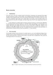
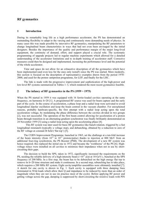
<strong>RF</strong> <strong>gymnastics</strong>1 IntroductionDur<strong>in</strong>g its remarkably long life as a high performance accelerator, <strong>the</strong> <strong>PS</strong> has demonstrated anoutstand<strong>in</strong>g flexibility to adapt to <strong>the</strong> vary<strong>in</strong>g and cont<strong>in</strong>uously more demand<strong>in</strong>g needs of physics. Inmany cases this was made possible by <strong>in</strong>novative <strong>RF</strong> <strong>gymnastics</strong>, manipulat<strong>in</strong>g <strong>the</strong> <strong>RF</strong> parameters tochange longitud<strong>in</strong>al beam characteristics <strong>in</strong> ways that had not even been envisaged by <strong>the</strong> <strong>in</strong>itialdesigners. Besides <strong>the</strong> importance of <strong>the</strong> quality and performance marg<strong>in</strong> of <strong>the</strong> major long-livedequipment, <strong>the</strong> cont<strong>in</strong>uity of demand, effort, and support played a crucial role. The systematicprogramm<strong>in</strong>g of upgrade projects led to regular mach<strong>in</strong>e experiments which allowed for a detailedunderstand<strong>in</strong>g of <strong>the</strong> accelerator limitations and to <strong>in</strong>-depth tra<strong>in</strong><strong>in</strong>g of accelerator staff. Correctivemeasures could <strong>the</strong>n be designed and implemented, <strong>in</strong>creas<strong>in</strong>g <strong>the</strong> performance level and <strong>the</strong> potentialof <strong>the</strong> whole accelerator.Time and space do not allow for an exhaustive description of all <strong>the</strong> <strong>gymnastics</strong> which havebeen implemented (and even less for <strong>the</strong> ones only tested!) s<strong>in</strong>ce <strong>the</strong> <strong>PS</strong> was started. More modestly,this section is focused on <strong>the</strong> description of representative examples drawn from <strong>the</strong> period 1970–2000, and used for <strong>the</strong> proton–antiproton programme, for LEP, and f<strong>in</strong>ally for <strong>the</strong> LHC.The l<strong>in</strong>k is made with <strong>the</strong> progressive improvement and sophistication of <strong>the</strong> high-power andlow-level <strong>RF</strong> systems summarized <strong>in</strong> Tables 1–3, which rendered <strong>the</strong> most recent <strong>gymnastics</strong> feasible.2 The <strong>in</strong>fancy of <strong>RF</strong> <strong>gymnastics</strong> <strong>in</strong> <strong>the</strong> <strong>PS</strong> (1959 ~ 1975)When <strong>the</strong> <strong>PS</strong> started <strong>in</strong> 1959 it was equipped with 16 ferrite-loaded cavities operat<strong>in</strong>g at <strong>the</strong> samefrequency, on harmonic h=20 [1]. A programmed <strong>RF</strong> source was used for beam capture and <strong>the</strong> earlypart of <strong>the</strong> cycle. In <strong>the</strong> course of acceleration, a phase loop and a radial loop were activated to avoidlongitud<strong>in</strong>al dipolar oscillation and keep <strong>the</strong> beam centred <strong>in</strong> <strong>the</strong> vacuum chamber. For unexpla<strong>in</strong>edreasons, probably hardware-specific, <strong>the</strong> first attempt with a radial loop act<strong>in</strong>g upon <strong>the</strong> totalacceleration voltage, by modulat<strong>in</strong>g <strong>the</strong> phase difference between <strong>the</strong> cavities divided <strong>in</strong> two groups[2], was not successful. The operation of <strong>the</strong> first beam control allow<strong>in</strong>g for acceleration of a protonbeam through transition <strong>in</strong> an alternat<strong>in</strong>g-gradient synchrotron was f<strong>in</strong>ally brilliantly demonstrated on24 November 1959 [3] us<strong>in</strong>g a radial loop act<strong>in</strong>g upon <strong>the</strong> accelerat<strong>in</strong>g phase [4].This <strong>RF</strong> system was later used for basic <strong>RF</strong> <strong>gymnastics</strong> like bunch rotation, triggered by a fastlongitud<strong>in</strong>al mismatch (typically a voltage step), and debunch<strong>in</strong>g, obta<strong>in</strong>ed by a reduction to zero of<strong>the</strong> <strong>RF</strong> voltage at constant B field (‘flat top’) [5].The <strong>CERN</strong> Improvement Programme, launched <strong>in</strong> 1965, set <strong>the</strong> challenge at a ten-fold <strong>in</strong>creaseof <strong>the</strong> beam <strong>in</strong>tensity (from 10 12 to 10 13 protons/pulse) thanks to <strong>in</strong>jection at 800 MeV from anadditional four-r<strong>in</strong>g synchrotron, <strong>the</strong> <strong>PS</strong> Booster (<strong>PS</strong>B). The development of a new <strong>RF</strong> system washence required; this replaced <strong>the</strong> <strong>in</strong>itial one <strong>in</strong> 1972 and became <strong>the</strong> ‘workhorse’ of <strong>the</strong> <strong>PS</strong> [6]. Highvoltagerelays were <strong>in</strong>stalled on all cavities to m<strong>in</strong>imize <strong>the</strong>ir impedance when not <strong>in</strong> use by shortcircuit<strong>in</strong>g<strong>the</strong>ir gaps.The decision to build <strong>the</strong> S<strong>PS</strong>, taken <strong>in</strong> 1972, significantly <strong>in</strong>creased <strong>the</strong> requirements on <strong>the</strong><strong>PS</strong>, need<strong>in</strong>g <strong>the</strong> reliable delivery of a high-<strong>in</strong>tensity beam (>10 13 p/p) at 10 GeV/c, bunched at <strong>the</strong> S<strong>PS</strong>frequency of 200 MHz. In a first step, <strong>the</strong> beam has to be debunched on <strong>the</strong> high energy flat top toremove its h=20 time structure and make it cont<strong>in</strong>uous. In a second step, rebunch<strong>in</strong>g has to take place,which requires a 200 MHz <strong>RF</strong> system. Eight cavity/amplifier assemblies were ultimately <strong>in</strong>stalled [7].A sketch for one cavity is shown <strong>in</strong> Fig. 1. Each cavity is equipped with three damp<strong>in</strong>g l<strong>in</strong>esterm<strong>in</strong>ated <strong>in</strong> 50 Ω loads which allow <strong>the</strong>ir Q and impedance to be reduced by more than an order ofmagnitude when <strong>the</strong>y are not <strong>in</strong> use (<strong>in</strong> practice most of <strong>the</strong> cycle). Before apply<strong>in</strong>g <strong>RF</strong> power andgett<strong>in</strong>g voltage across <strong>the</strong> gap, damp<strong>in</strong>g is suppressed by short-circuit<strong>in</strong>g <strong>the</strong> resistive loads with PIN1
frequency difference. Therefore <strong>the</strong> separation between <strong>the</strong> two sets of bunches decreases until <strong>the</strong>yare superimposed <strong>in</strong> azimuth. If <strong>the</strong> <strong>RF</strong> is <strong>the</strong>n suddenly switched to <strong>the</strong> average frequency (f 1 + f 2 )/2on both groups and <strong>the</strong> voltage <strong>in</strong>creased by a large enough factor, pairs of bunches can berecomb<strong>in</strong>ed <strong>in</strong> <strong>the</strong> correspond<strong>in</strong>g large buckets.+Δfh 0 f REV−Δf2 n bunches separated<strong>in</strong> energy and azimuthAzimuthal slipFig. 2: Slip stack<strong>in</strong>gCapture on h 0of 2 bunches/bucketFigure 3 shows a mounta<strong>in</strong> range display of a typical result with a total <strong>in</strong>jected <strong>in</strong>tensity of10 13 p/p. Feedforward beam load<strong>in</strong>g compensation was essential for a correct <strong>RF</strong> operation at such ahigh <strong>in</strong>tensity. However, this process also suffered from excessive beam loss, probably due to <strong>the</strong>presence of a large proportion of particles with very large emittances after filamentation and to limitedacceptances at low energy.Fig. 3: Mounta<strong>in</strong> range display of longitud<strong>in</strong>al recomb<strong>in</strong>ation by slip stack<strong>in</strong>g at 800 MeVHence a similar but much more sophisticated process was successfully implemented at25 GeV and used until 1989. Aga<strong>in</strong> two <strong>RF</strong> groups are necessary. Comb<strong>in</strong><strong>in</strong>g four cavities operat<strong>in</strong>gat <strong>the</strong> same peak voltage , with two cavities on h=20, one on h=19 and one on h=21, each of <strong>the</strong>segroups generates a 100% amplitude modulation at <strong>the</strong> revolution frequency ⁄ 2 of a carrier onh=20. Indeed: cos19 2 cos20 cos21 2 cos20 1cos↑Carrier onh=20↑Peak amplitude modulationat <strong>the</strong> revolution frequencyWith a proper phas<strong>in</strong>g of <strong>the</strong> different harmonics with respect to <strong>the</strong> beam, <strong>the</strong> maximumamplitude of a group can be centred onto a set of five bunches. Start<strong>in</strong>g with two sets of bunchesdiametrically opposite <strong>in</strong> <strong>the</strong> <strong>PS</strong>, each set ‘sees’ a maximum voltage from its <strong>RF</strong> group and am<strong>in</strong>imum from <strong>the</strong> o<strong>the</strong>r one. This situation is illustrated <strong>in</strong> Fig. 4. Separate beam controls can hencehandle both sets separately, giv<strong>in</strong>g <strong>the</strong>m a difference <strong>in</strong> energy, and ‘slip stack<strong>in</strong>g’ beg<strong>in</strong>s.3
Fig. 4: <strong>RF</strong> peak voltage and beam at <strong>the</strong> beg<strong>in</strong>n<strong>in</strong>g of longitud<strong>in</strong>al recomb<strong>in</strong>ation at 25 GeVIn that case <strong>the</strong>re is no need to recapture pairs of bunches <strong>in</strong> <strong>the</strong> same bucket: <strong>the</strong> beam issimply ejected onto <strong>the</strong> target when both beam sets are azimuthally superimposed. The mounta<strong>in</strong>range display <strong>in</strong> Fig. 5 shows a typical result at 10 13 p/p.Fig. 5: Mounta<strong>in</strong> range display of longitud<strong>in</strong>al recomb<strong>in</strong>ation at 25 GeVThe practical implementation of this process was ra<strong>the</strong>r complex. Controls and low-level <strong>RF</strong>had to provide all <strong>the</strong> necessary signals, and <strong>the</strong> ferrite cavities had to operate <strong>in</strong> three groups tuned atdifferent frequencies and with different voltage programmes. Gap relays were momentarily activatedon <strong>the</strong> four cavities used on h=19 and h=21 at <strong>the</strong> beg<strong>in</strong>n<strong>in</strong>g of <strong>the</strong> flat top to reduce <strong>the</strong>ir impedancewhen <strong>the</strong>y were chang<strong>in</strong>g tune.Ano<strong>the</strong>r strongly non-adiabatic technique was successfully applied for a few years, <strong>in</strong>comb<strong>in</strong>ation with <strong>the</strong> previous one. With a specially designed <strong>RF</strong> deflect<strong>in</strong>g dipole <strong>in</strong> <strong>the</strong> transfer l<strong>in</strong>ebetween <strong>the</strong> <strong>PS</strong>B and <strong>the</strong> <strong>PS</strong>, bunches of two <strong>PS</strong>B r<strong>in</strong>gs were <strong>in</strong>terlaced (Fig. 6) so that each <strong>PS</strong>bucket captured two of <strong>the</strong>m [12]. This ‘funnell<strong>in</strong>g’ process is <strong>in</strong>tr<strong>in</strong>sically imperfect, both <strong>in</strong> <strong>the</strong>transverse phase plane because all particles <strong>in</strong> a bunch do not get <strong>the</strong> same deflection, and <strong>in</strong> <strong>the</strong>longitud<strong>in</strong>al phase plane because capture is strongly non-adiabatic, trigger<strong>in</strong>g an <strong>in</strong>tense filamentationand a large blow-up. An acceptable operational compromise was never<strong>the</strong>less found — adjust<strong>in</strong>g <strong>the</strong>distance between bunches to optimize <strong>the</strong> overall result and m<strong>in</strong>imize beam loss (Fig. 7).4
Fig. 6: ‘Funnell<strong>in</strong>g’ with an <strong>RF</strong> dipole <strong>in</strong> <strong>the</strong> <strong>PS</strong>B–<strong>PS</strong> transfer l<strong>in</strong>eFig. 7: Average and peak beam current dur<strong>in</strong>g a complete acceleration cycle with <strong>the</strong> <strong>RF</strong> dipoleThe needs of <strong>the</strong> upgrade programme launched <strong>in</strong> 1983 and based on <strong>the</strong> Antiproton Collector(ACOL) could, however, not be met with <strong>the</strong> previous methods of preparation of <strong>the</strong> antiprotonproduction beam. Bunch rotation of <strong>the</strong> antiproton bunches enter<strong>in</strong>g ACOL was <strong>in</strong>deed foreseen, toquickly reduce <strong>the</strong>ir energy spread by a large factor, without resort<strong>in</strong>g to any cool<strong>in</strong>g. Hence <strong>the</strong>proton bunches had to have a reproducible and as short as possible bunch length. A two-step quasiadiabaticprocess was <strong>the</strong>refore proposed, us<strong>in</strong>g bunch merg<strong>in</strong>g and batch compression [13].Merg<strong>in</strong>g pairs of bunches is obta<strong>in</strong>ed at constant B field by chang<strong>in</strong>g <strong>the</strong> <strong>RF</strong> voltage seen by <strong>the</strong>beam from h=20 to h=10, with <strong>the</strong> h=10 stable phase centred <strong>in</strong> <strong>the</strong> middle of <strong>the</strong> h=20 buckets (Fig.8).Fig. 8: <strong>RF</strong> voltages and buckets dur<strong>in</strong>g bunch-pair merg<strong>in</strong>g5
In practice, cavities have to be split <strong>in</strong>to four groups, operat<strong>in</strong>g at three different frequencies:one group of four cavities is at 0 V, while three o<strong>the</strong>r groups of two cavities are controlled as <strong>in</strong>Fig. 11. The low-level <strong>RF</strong> has to be able to provide all <strong>the</strong>se harmonics with <strong>the</strong> correct phas<strong>in</strong>g. Eventhough gap relays are repeatedly activated to short-circuit gaps when cavities are at 0 V, <strong>the</strong> voltage<strong>in</strong>duced by <strong>the</strong> beam when cavities are at low voltage is a major source of imperfection. It wasimpractical to implement feedforward beam load<strong>in</strong>g compensation <strong>in</strong> that context. An upgradeprogramme was <strong>the</strong>refore launched for reliably reduc<strong>in</strong>g <strong>the</strong> impedance of all cavities, <strong>in</strong>dependentlyof <strong>the</strong>ir tune, implement<strong>in</strong>g a fast <strong>RF</strong> feedback [14][15]. That implied <strong>the</strong> modification of <strong>the</strong> highpoweramplifier of every cavity (Fig. 12). Beam performance <strong>in</strong> <strong>the</strong>se conditions was much betterthan with funnel<strong>in</strong>g by means of <strong>the</strong> <strong>RF</strong> dipole. A typical result at 1.6×10 13 p/p is shown <strong>in</strong> Fig. 13.Fig. 12: Fast <strong>RF</strong> feedback on a <strong>PS</strong> ferrite-loaded cavityFig. 13: Mounta<strong>in</strong> range display of batch compression (h=10 → h=20) at 25 GeVHowever, transient beam load<strong>in</strong>g rema<strong>in</strong>ed a source of imperfection because <strong>the</strong> equivalentfill<strong>in</strong>g time of <strong>the</strong> feedback-equipped cavities is of <strong>the</strong> order of 300 ns, which makes <strong>the</strong> first bunchesexperience a different beam-<strong>in</strong>duced voltage than <strong>the</strong> last ones. This was addressed with a one-turndelay feedback [16] which fur<strong>the</strong>r decreased impedance by a factor four <strong>in</strong> a limited bandwidth of ±3revolution frequency harmonics around <strong>the</strong> cavity tune. The reduction of transient beam load<strong>in</strong>g on acavity with five bunches on h=20 (end of <strong>the</strong> batch compression process) is shown <strong>in</strong> Fig. 14.Fig. 14: Beam-<strong>in</strong>duced voltage <strong>in</strong> a cavity without (top) and with (bottom) one-turn delay feedback7
All <strong>the</strong>se measures and renewed low-level electronics are nowadays comb<strong>in</strong>ed to provide <strong>the</strong>performance regularly achieved for <strong>the</strong> Antiproton Decelerator (Fig. 15).Fig. 15: Mounta<strong>in</strong> range display of batch compression (h=8 → h=20) at 25 GeV for <strong>the</strong> AD3.2 <strong>RF</strong> <strong>gymnastics</strong> for antiproton accelerationThe ma<strong>in</strong> difficulty with <strong>the</strong> acceleration of antiprotons <strong>in</strong> <strong>the</strong> <strong>PS</strong> resulted from <strong>the</strong> large longitud<strong>in</strong>alemittance of <strong>the</strong> bunch. To maximize <strong>the</strong> <strong>RF</strong> bucket acceptance, h=6 was <strong>the</strong>refore used as <strong>the</strong> lowestharmonic number compatible with <strong>the</strong> tun<strong>in</strong>g range of <strong>the</strong> ferrite cavities. However, it rema<strong>in</strong>ed<strong>in</strong>sufficient for a ‘conventional’ non-adiabatic bunch rotation to provide a bunch shorter than 5 ns at25 GeV that could fit <strong>in</strong>to a s<strong>in</strong>gle 200 MHz <strong>RF</strong> bucket <strong>in</strong> <strong>the</strong> S<strong>PS</strong>. That was solved with a more<strong>in</strong>volved <strong>gymnastics</strong> comb<strong>in</strong><strong>in</strong>g <strong>RF</strong> on h=6 and h=12 and vary<strong>in</strong>g amplitudes and phase dur<strong>in</strong>g bunchrotation to l<strong>in</strong>earize <strong>the</strong> focus<strong>in</strong>g voltage only over <strong>the</strong> <strong>in</strong>stantaneous length of <strong>the</strong> bunch (Fig. 16).Synchronization with <strong>the</strong> S<strong>PS</strong> revolution frequency to about 0.5 ns rema<strong>in</strong>ed a demand<strong>in</strong>g challengebecause of <strong>the</strong> large voltage and phase transients due to <strong>the</strong> voltage and phase manipulations requiredby <strong>the</strong> bunch rotation <strong>gymnastics</strong>.Fig. 16: Bunch at end of bunch rotation on h=6 (left), h=6+12 (right) at 25 GeV8
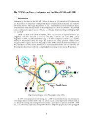
For LEAR, <strong>the</strong> <strong>PS</strong> had for <strong>the</strong> first time to decelerate beam from 3.57 GeV/c down to609 MeV/c. To stay with<strong>in</strong> <strong>the</strong> tun<strong>in</strong>g range of <strong>the</strong> ferrite cavities, <strong>the</strong> <strong>RF</strong> system had to operate onh=10 <strong>in</strong>stead of h=6. To deal with very low bunch <strong>in</strong>tensities, <strong>the</strong> beam control was based on anaccurate frequency programme and an AC-coupled phase loop, without radial loop.4 Electrons and positrons for LEPIn <strong>the</strong> context of LEP, <strong>the</strong> suggestion was made <strong>in</strong> 1980 [17], and quickly adopted, to modify <strong>the</strong> S<strong>PS</strong>and <strong>PS</strong> as electron–positron <strong>in</strong>jectors. The <strong>PS</strong> was charged with accelerat<strong>in</strong>g <strong>the</strong> electrons andpositrons provided by <strong>the</strong> EPA from 500 MeV up to <strong>the</strong> energy of 3.5 GeV at which <strong>the</strong>y could betransferred to <strong>the</strong> S<strong>PS</strong> [18]. A new <strong>RF</strong> system with two cavities operat<strong>in</strong>g at 114 MHz was <strong>the</strong>refore<strong>in</strong>stalled <strong>in</strong> 1986 [19]. To preserve <strong>the</strong> capability to accelerate high-<strong>in</strong>tensity proton beams, <strong>the</strong>secavities were equipped with HOM dampers and short-circuited by copper bars moved dur<strong>in</strong>g <strong>the</strong>dead-time between lepton and proton cycles (Fig. 17).Contrary to most o<strong>the</strong>r lepton synchrotrons where damp<strong>in</strong>g times are short so that bunchesreach <strong>the</strong>ir equilibrium size soon after <strong>in</strong>jection, <strong>the</strong> low radiation loss <strong>in</strong> <strong>the</strong> <strong>PS</strong> made bunches keep a‘memory’ of <strong>the</strong> early part of <strong>the</strong> cycle. Special <strong>gymnastics</strong> were implemented tak<strong>in</strong>g <strong>in</strong>to account thiseffect [18] to tailor <strong>the</strong> bunches to <strong>the</strong> needs of <strong>the</strong> S<strong>PS</strong> by <strong>the</strong> comb<strong>in</strong>ed action of <strong>RF</strong> and of twoRob<strong>in</strong>son wigglers controll<strong>in</strong>g <strong>the</strong> damp<strong>in</strong>g partition numbers. Without <strong>the</strong>se wigglers <strong>the</strong> horizontalbetatron oscillations would be antidamped (J x = -1) as <strong>the</strong> <strong>PS</strong> has a comb<strong>in</strong>ed-function lattice [20].One scenario was to use <strong>the</strong> 114 MHz system alone on h=240: at <strong>the</strong> end of acceleration, bunchesneeded ‘expansion’ to <strong>the</strong> proper emittance which was obta<strong>in</strong>ed by reduc<strong>in</strong>g <strong>the</strong> damp<strong>in</strong>g partitionnumber J ε by 3.8 units. Ano<strong>the</strong>r scenario was based on acceleration with <strong>the</strong> ferrite cavities on h=16or h=8: at 3.5 GeV, bunches needed compression which was obta<strong>in</strong>ed by a quasi-adiabatic <strong>in</strong>crease ofvoltage at 114 MHz and a small reduction of J ε by 0.9 unit. The scenario f<strong>in</strong>ally preferred <strong>in</strong> operationused <strong>the</strong> same J ε as <strong>in</strong> <strong>the</strong> expansion case, but it provided bunches twice as long, focus<strong>in</strong>g <strong>the</strong> beamwith one quarter of <strong>the</strong> <strong>RF</strong> voltage at 114 MHz and accelerat<strong>in</strong>g it on <strong>the</strong> crest of a 200 kV, h=8 <strong>RF</strong> at3.8 MHz.The two 114 MHz cavities were removed after <strong>the</strong> end of LEP, <strong>in</strong> December 2000.Fig. 17: 114 MHz cavity9
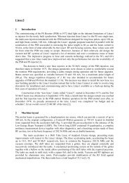
5 Protons for <strong>the</strong> LHCThe lum<strong>in</strong>osity goals <strong>in</strong> <strong>the</strong> LHC require proton beams with a brightness exceed<strong>in</strong>g <strong>the</strong> exist<strong>in</strong>gcapabilities of <strong>the</strong> L<strong>in</strong>ac2–<strong>PS</strong>B–<strong>PS</strong>–S<strong>PS</strong> cascade. An upgrade was <strong>the</strong>refore launched [21] based onthree ma<strong>in</strong> <strong>in</strong>gredients: (i) division by 2 of <strong>the</strong> beam brightness <strong>in</strong> <strong>the</strong> <strong>PS</strong>B by <strong>the</strong> use of two pulses tofill <strong>the</strong> <strong>PS</strong>, (ii) division by 1.5 of space-charge tune spread <strong>in</strong> <strong>the</strong> <strong>PS</strong> by <strong>in</strong>creas<strong>in</strong>g <strong>the</strong> <strong>in</strong>jection energyto 1.4 GeV, and (iii) suppression of <strong>the</strong> transition bottle neck <strong>in</strong> <strong>the</strong> S<strong>PS</strong> by <strong>in</strong>ject<strong>in</strong>g at 25 GeV. Thelongitud<strong>in</strong>al stack<strong>in</strong>g of two <strong>PS</strong>B batches <strong>in</strong> <strong>the</strong> <strong>PS</strong> is made possible by hav<strong>in</strong>g a s<strong>in</strong>gle bunch <strong>in</strong> each<strong>PS</strong>B r<strong>in</strong>g, operat<strong>in</strong>g <strong>the</strong> <strong>RF</strong> on h=1, and chang<strong>in</strong>g to <strong>the</strong> beam transfer scheme sketched <strong>in</strong> Fig. 18.The harmonic number also had to be changed <strong>in</strong> <strong>the</strong> <strong>PS</strong>, and <strong>the</strong> <strong>in</strong>itial choice was for h=8.Fig. 18: <strong>PS</strong>B–<strong>PS</strong> beam transfer before and after modification for <strong>the</strong> LHCS<strong>in</strong>gle-batch fill<strong>in</strong>g of <strong>the</strong> <strong>PS</strong> rema<strong>in</strong>s possible, with two bunches per <strong>PS</strong>B r<strong>in</strong>g (<strong>RF</strong> on h=2)and <strong>RF</strong> on h=8 <strong>in</strong> <strong>the</strong> <strong>PS</strong>. Once implemented at <strong>the</strong> beg<strong>in</strong>n<strong>in</strong>g of 1998, all beams delivered by <strong>the</strong> <strong>PS</strong>had to be modified to operate with new harmonic numbers and revised <strong>gymnastics</strong> [22]. In particular,<strong>the</strong> <strong>in</strong>verse process to merg<strong>in</strong>g pairs of bunches, splitt<strong>in</strong>g bunches <strong>in</strong>to two, became rout<strong>in</strong>e operation[23].Beyond beam brightness, <strong>the</strong> <strong>PS</strong> also has to give its f<strong>in</strong>al time structure to <strong>the</strong> proton beam,for example transform<strong>in</strong>g it <strong>in</strong>to a 40 MHz bunch tra<strong>in</strong> (25 ns spac<strong>in</strong>g between bunches) <strong>in</strong> <strong>the</strong>nom<strong>in</strong>al case. Debunch<strong>in</strong>g on h=16 followed by rebunch<strong>in</strong>g on h=84 (40 MHz) at 25 GeV was <strong>the</strong>process <strong>in</strong>itially foreseen for that purpose (Fig. 19) [21]. A fixed-tune 40 MHz <strong>RF</strong> system was<strong>the</strong>refore built and <strong>in</strong>stalled <strong>in</strong> <strong>the</strong> <strong>PS</strong> <strong>in</strong> 1996 [24]. It was complemented <strong>in</strong> 1998 with an 80 MHz <strong>RF</strong>system [25] to allow for <strong>the</strong> bunch rotation necessary to reduce bunch length down to 4 ns, as requiredby <strong>the</strong> S<strong>PS</strong>. All of <strong>the</strong>se cavities are equipped with a telescopic mechanical short-circuit which almostperfectly closes <strong>the</strong>ir gaps when <strong>the</strong>y are not <strong>in</strong> use (Fig. 20). Although open<strong>in</strong>g and clos<strong>in</strong>g takeapproximately one second, movements are planned to take place only a few times per day,immediately before and after fill<strong>in</strong>g <strong>the</strong> LHC. In addition, a fast <strong>RF</strong> feedback is implemented on bothsystems to m<strong>in</strong>imize impedance when <strong>the</strong> gap is open.10
Fig. 19: Initial process for generat<strong>in</strong>g a bunch tra<strong>in</strong> for <strong>the</strong> LHC with <strong>the</strong> nom<strong>in</strong>al bunch distance of 25 nsFig. 20: 40 and 80 MHz cavitiesHowever, it quickly proved impossible to achieve <strong>the</strong> necessary emittance and bunch lengthafter recapture [26], even after <strong>the</strong> removal of <strong>the</strong> 114 MHz cavities. A new process was <strong>the</strong>nproposed [27] which avoids debunch<strong>in</strong>g, provides a large flexibility <strong>in</strong> <strong>the</strong> beam time structure, andallows for <strong>the</strong> preservation of a gap where <strong>the</strong> extraction kicker can rise, avoid<strong>in</strong>g particle loss. It isbased on multiple successive splitt<strong>in</strong>gs, <strong>in</strong>clud<strong>in</strong>g one splitt<strong>in</strong>g <strong>in</strong>to three (‘triple splitt<strong>in</strong>g’). In a slightvariant with respect to <strong>the</strong> scheme <strong>in</strong>itially foreseen and sketched <strong>in</strong> Fig. 18, six bunches delivered <strong>in</strong>two batches by <strong>the</strong> <strong>PS</strong>B are captured on harmonic h=7 <strong>in</strong> <strong>the</strong> <strong>PS</strong>. Each bunch is <strong>the</strong>n split <strong>in</strong>to 12 <strong>in</strong>two steps, as shown <strong>in</strong> Fig. 21.11
Fig. 21: Multiple splitt<strong>in</strong>g scenario for <strong>the</strong> nom<strong>in</strong>al bunch distance of 25 ns for <strong>the</strong> LHCTriple splitt<strong>in</strong>g is started as soon as <strong>the</strong> second batch is received, which provides 18consecutive bunches on h=21. The beam is <strong>the</strong>n accelerated on this harmonic up to <strong>the</strong> 25 GeV flattop,where each bunch is twice split <strong>in</strong>to two to give 72 consecutive bunches on h=84. This leaves a320 ns gap <strong>in</strong> <strong>the</strong> bunch tra<strong>in</strong> for <strong>the</strong> rise-time of <strong>the</strong> ejection kicker.Triple splitt<strong>in</strong>g requires three simultaneous <strong>RF</strong> harmonics (h=7, h=14 and h=21) which can beprovided by <strong>the</strong> ferrite cavities divided <strong>in</strong> three different tun<strong>in</strong>g groups. The relative phases betweenharmonics are such that a stable phase on h=21 and an unstable phase on h=14 co<strong>in</strong>cide with <strong>the</strong>stable phase on h=7. Start<strong>in</strong>g with h=7 alone, <strong>the</strong> effect of <strong>in</strong>creas<strong>in</strong>g <strong>the</strong> voltages on h=14 and h=21is to flatten <strong>the</strong> bunch (t = 7 ms <strong>in</strong> Fig. 22). In phase space, two new stable po<strong>in</strong>ts emerge close to <strong>the</strong><strong>in</strong>itial one, encircled by three buckets. Us<strong>in</strong>g numerically determ<strong>in</strong>ed laws of variation, <strong>the</strong>se threeareas are kept equal throughout <strong>the</strong> process so that layers of <strong>in</strong>creas<strong>in</strong>g emittance <strong>in</strong> <strong>the</strong> <strong>in</strong>itial bunchare progressively peeled off and accumulated evenly <strong>in</strong>to <strong>the</strong> three new buckets. Provided that <strong>the</strong> rateof change of <strong>the</strong> voltages is sufficiently slow, <strong>the</strong> particles of <strong>the</strong> <strong>in</strong>itial bunch are gradually captured<strong>in</strong> <strong>the</strong> new buckets whose area grows as <strong>the</strong> voltage decreases on h=7 and <strong>in</strong>creases on h=21(t = 14 ms). Three equal bunches are f<strong>in</strong>ally obta<strong>in</strong>ed, each with <strong>the</strong> same distribution of particledensity as <strong>the</strong> <strong>in</strong>itial one (t = 25 ms). The low-level <strong>RF</strong> generates <strong>the</strong> different harmonics, preciselycontroll<strong>in</strong>g <strong>the</strong>ir relative phases. A beam phase loop is active throughout <strong>the</strong> process, controll<strong>in</strong>g <strong>the</strong>sum of all harmonics whose relative phase is rigidly fixed. A typical result at <strong>the</strong> nom<strong>in</strong>al <strong>in</strong>tensity for<strong>the</strong> LHC is shown <strong>in</strong> Fig. 23(a).Fig. 22: Pr<strong>in</strong>ciple of triple splitt<strong>in</strong>g12
Quadruple splitt<strong>in</strong>g [Fig. 23(b)] at 25 GeV is obta<strong>in</strong>ed by cascad<strong>in</strong>g two double-splitt<strong>in</strong>gsteps. Three groups of cavities are also employed, operat<strong>in</strong>g on harmonics 21, 42 and 84 respectively.Gett<strong>in</strong>g voltage on h=42 required <strong>the</strong> <strong>in</strong>stallation of an additional <strong>RF</strong> system operat<strong>in</strong>g at 20 MHz[28].a: Triple splitt<strong>in</strong>g at 1.4 GeV b: Quadruple splitt<strong>in</strong>g at 25 GeVFig. 23: Mounta<strong>in</strong> range displays when generat<strong>in</strong>g a bunch tra<strong>in</strong> at <strong>the</strong> nom<strong>in</strong>al <strong>in</strong>tensity for <strong>the</strong> LHC, with <strong>the</strong>nom<strong>in</strong>al 25ns bunch distanceThe relative phase between harmonics is rigidly fixed and a beam phase loop suppressescollective oscillations with respect to <strong>the</strong> <strong>RF</strong> sum voltage. Simulation predicts that <strong>the</strong> longitud<strong>in</strong>alemittance will not <strong>in</strong>crease, and this is also observed <strong>in</strong> practice, as long as <strong>the</strong> beam is kept stable at<strong>the</strong> beg<strong>in</strong>n<strong>in</strong>g and dur<strong>in</strong>g <strong>the</strong> process. At <strong>the</strong> end of <strong>the</strong> splitt<strong>in</strong>g process at 25 GeV, bunches arerotated by rais<strong>in</strong>g quickly to full voltage, first <strong>the</strong> 40 MHz (h=84) system, <strong>the</strong>n, 180 μs later, <strong>the</strong>80 MHz (h=168) system [Fig. 24(a)]. The result<strong>in</strong>g bunch [Fig. 24(b)] is <strong>the</strong>n ready for transfer to <strong>the</strong>S<strong>PS</strong>.a: Voltages and (simulated) bunch contour <strong>in</strong> <strong>the</strong> phase plane b: F<strong>in</strong>al bunch (measurement)Fig. 24: Rotation of a nom<strong>in</strong>al bunch for <strong>the</strong> LHC at 25 GeV13
Fig. 25: Generation of a bunch tra<strong>in</strong> with 75 ns between bunchesThe comb<strong>in</strong>ation of <strong>the</strong> successive splitt<strong>in</strong>gs from h=7 to h=84 with this bunch rotationprovides <strong>the</strong> nom<strong>in</strong>al bunch emittance and length, while avoid<strong>in</strong>g beam loss at <strong>PS</strong> ejection dur<strong>in</strong>g <strong>the</strong>rise-time of <strong>the</strong> ejection kicker. It has been adopted as <strong>the</strong> basic operational scheme for <strong>the</strong> generationof <strong>the</strong> proton beam for <strong>the</strong> LHC.An additional advantageous feature is that it easily allows for hav<strong>in</strong>g gaps <strong>in</strong> <strong>the</strong> bunch tra<strong>in</strong>by send<strong>in</strong>g no beam from certa<strong>in</strong> <strong>PS</strong>B r<strong>in</strong>gs, or for hav<strong>in</strong>g a 50 ns time <strong>in</strong>terval between bunches byremov<strong>in</strong>g <strong>the</strong> last splitt<strong>in</strong>g step at 25 GeV.Us<strong>in</strong>g <strong>the</strong> same k<strong>in</strong>d of <strong>gymnastics</strong> with different sets of harmonics, a 75 ns time <strong>in</strong>tervalbetween bunches is also available. Start<strong>in</strong>g from six bunches on h=7, as <strong>in</strong> <strong>the</strong> nom<strong>in</strong>al case, twosplitt<strong>in</strong>gs <strong>in</strong>to two are applied. The first one is at <strong>in</strong>jection energy (1.4 GeV), giv<strong>in</strong>g 12 bunches onh=14 which are <strong>the</strong>n accelerated on that harmonic up to high energy. The second splitt<strong>in</strong>g takes placeat 25 GeV, giv<strong>in</strong>g 24 bunches on h=28 (13 MHz). The whole process is sketched <strong>in</strong> Fig. 25.The <strong>RF</strong> system that provides voltage at this frequency is <strong>the</strong> same one that can operate at 20 MHz[28]. This scheme is also operational and typical results are shown <strong>in</strong> Fig. 26. Beam can even bedelivered every 2.4 s by <strong>the</strong> <strong>PS</strong>, us<strong>in</strong>g a s<strong>in</strong>gle batch from <strong>the</strong> <strong>PS</strong>B.a: Splitt<strong>in</strong>g <strong>in</strong> two at 1.4 GeV b: Splitt<strong>in</strong>g <strong>in</strong> two at 25 GeVFig. 26: Mounta<strong>in</strong> range displays when generat<strong>in</strong>g a bunch tra<strong>in</strong> at <strong>the</strong> nom<strong>in</strong>al <strong>in</strong>tensity for <strong>the</strong> LHC, with a75 ns bunch distance14
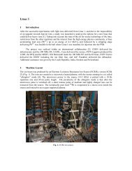
6 Heavy ions for <strong>the</strong> LHCFor ions heavier than protons, <strong>the</strong> beam for <strong>the</strong> LHC does not pass through <strong>the</strong> <strong>PS</strong>B. It is prepared <strong>in</strong><strong>the</strong> Low Energy Ion R<strong>in</strong>g (LEIR) which sends it directly to <strong>the</strong> <strong>PS</strong>. The role of <strong>the</strong> <strong>PS</strong> is to accelerateand adapt <strong>the</strong> beam from LEIR to <strong>the</strong> needs of <strong>the</strong> downstream mach<strong>in</strong>es, impos<strong>in</strong>g <strong>the</strong> 100 ns bunchspac<strong>in</strong>g required by LHC experiments and <strong>the</strong> bunch charge, bunch length, and bunch frequencywhich are acceptable to <strong>the</strong> S<strong>PS</strong>.For that purpose ‘batch expansion’, <strong>the</strong> reverse process to ‘batch compression’ applied to <strong>the</strong>AD production beam, is applied twice at an <strong>in</strong>termediate energy, separated by a splitt<strong>in</strong>g <strong>in</strong>to two[29]. Start<strong>in</strong>g from two LEIR bunches captured and accelerated on h=16 up to a magnetic plateau, <strong>the</strong>bunch spac<strong>in</strong>g is <strong>in</strong>creased dur<strong>in</strong>g <strong>the</strong> first batch expansion by progressively decreas<strong>in</strong>g <strong>the</strong> harmonicnumber from h=16 down to h=12. Bunches are <strong>the</strong>n split <strong>in</strong>to two on h=24. The correct spac<strong>in</strong>gbetween bunches is f<strong>in</strong>ally obta<strong>in</strong>ed by a second batch expansion decreas<strong>in</strong>g <strong>the</strong> harmonic number toh=21. This full process was demonstrated experimentally <strong>in</strong> August 2009 (Fig. 27).Additional <strong>gymnastics</strong> take place at top energy (86.7 Tm), after acceleration on h=21 throughtransition. First, <strong>the</strong> four bunches <strong>in</strong> consecutive h=21 buckets are transferred from <strong>the</strong> ferrite cavitysystem to <strong>the</strong> fixed-frequency 80 MHz one (h=169), to precisely set a distance between bunches thatcorresponds to S<strong>PS</strong> buckets. Optionally, if space charge proves problematic at <strong>in</strong>jection energy <strong>in</strong> <strong>the</strong>S<strong>PS</strong>, bunches could be split <strong>in</strong>to two to fit <strong>in</strong>to pairs of consecutive 200 MHz buckets. The f<strong>in</strong>albunch pattern sees 5 ns between <strong>the</strong> ‘bunchlets’ of each pair and 95 ns between <strong>the</strong> nearest neighboursof consecutive pairs.7 SummaryFig. 27: Batch expansions and splitt<strong>in</strong>g of lead ionsThe <strong>PS</strong> has progressed remarkably <strong>in</strong> capability s<strong>in</strong>ce its start, fifty years ago. It is nowadaysequipped with a total of five multi-cavity <strong>RF</strong> systems (Table 1) which provide <strong>the</strong> means to cover abroad range of harmonic numbers at high beam <strong>in</strong>tensity (Table 2). The low-level <strong>RF</strong> and <strong>the</strong> overall15
control set-up (tim<strong>in</strong>gs, voltage waveform, etc.) are of an unprecedented complexity (Table 3). It tookfifty years of dedicated efforts to ga<strong>in</strong> <strong>the</strong> experience and knowledge required to design and mastersuch an <strong>in</strong>volved set-up. With its sets of <strong>gymnastics</strong> <strong>in</strong> regular use, <strong>the</strong> <strong>PS</strong> can reasonably be claimedto have today <strong>the</strong> most sophisticated and complex mode of <strong>RF</strong> operation ever implemented <strong>in</strong> asynchrotron.16
Table 1: High power <strong>RF</strong> systemsName[Ref.]Marelli[1]C10[6]C200[7]C114[19]C40[24]C80[25]C20[28]Cavity typeFerrite-loadedcoaxial resonatorFerrite-loadedcoaxial resonatorPill-box withceramic gapEvacuated with noseconesEvacuated withcapacitive load<strong>in</strong>gEvacuated withcapacitive load<strong>in</strong>gFerrite-loadedcoaxial resonatorFrequencyrangeTun<strong>in</strong>g2–10 MHz Fast over <strong>the</strong> full range(ferrite bias)2.6–9.5 MHz Fast over <strong>the</strong> full range(ferrite bias)200 ± 0.5 MHz Slow (piston withstepp<strong>in</strong>g motor) on allcavities + Fast (pistonwith l<strong>in</strong>ear actuator) ontwo cavities114.511 MHz Slow (piston withstepp<strong>in</strong>g motor)40.055 MHz Slow (piston withstepp<strong>in</strong>g motor)80.100 MHz Slow (piston withstepp<strong>in</strong>g motor)13.3 + 20 MHz Slow (HV switch) + fastover limited range(ferrite bias)NumberofcavitiesVoltage /cavity<strong>RF</strong>power /cavityDate of<strong>in</strong>stallation16 8 kV > 5 kW 1959 197311 20 kV 90 kW 19728 30 kV 20 kW 1977–19792 500 kV 50 kW 1986 20012 300 kV 400 kW 19963 300 kV 400 kW 19982 20 kV 50 kW 2002Date ofremoval18
Start<strong>in</strong>gyearTable 2: Evolution of <strong>RF</strong> <strong>gymnastics</strong>Operation Ma<strong>in</strong> users <strong>RF</strong> systems runn<strong>in</strong>g simultaneouslySystems Harmonics Freq.groupsAmpl.groups16 × Marelli cavities h= 20 1 1ISR1–4 × C200 cavities h= n × 20 1 21959 Acceleration on h=20 Experiments1978 Controlled longitud<strong>in</strong>al blow-up High <strong>in</strong>tensityusers(21 h=84)+ bunch compressionLHC 10 × C10 cavities h= 7 + 14 +21 3 41 × C40 cavities h= 84 1 12 × C80 cavities h= 168 1 119
Table 3: Means of impedance reduction / beam load<strong>in</strong>g compensationName Frequency Beam load<strong>in</strong>g compensation / impedance reduction Date of Date of Ref.scheme<strong>in</strong>stallation removalMarelli 2–10 MHz NoneC10 2.6–9.5 MHz Gap short-circuit with HV relays (when not <strong>in</strong> use) 1972 [6]Feedforward beam load<strong>in</strong>g compensation 1978 1988 [10]Wide-band feedback 1988 [15]One-turn delay feedbacks 1990 [16]C200 ~200 MHz De-Q-<strong>in</strong>g with resistive loads us<strong>in</strong>g PIN-diode switches 1977 [7](when not <strong>in</strong> use)Driver mismatchC114 114.511 MHz Short-circuit arm (when not <strong>in</strong> use) 1986 2001 [19]HOM dampersC40 40.055 MHz Telescopic short circuit (when not <strong>in</strong> use) 1996 [24]HOM dampersWide-band feedbackC80 80.100 MHz Telescopic short circuit (when not <strong>in</strong> use) 1998 [25]HOM dampersWide-band feedbackC20 13.3 + 20 MHz Gap short-circuit with HV relays (when not <strong>in</strong> use) 2002 [28]Wide-band feedback20
References[1] E. Regenstreif (Ed.), The <strong>CERN</strong> Proton Synchrotron, <strong>CERN</strong> 59-29 (1959), pp.159–226.[2] W. Schnell, Remarks on <strong>the</strong> phase lock system of <strong>the</strong> <strong>CERN</strong> Proton Synchrotron, <strong>in</strong> Proceed<strong>in</strong>gs of<strong>the</strong> second International Conference on High Energy Accelerators and Instrumentation, Geneva,Switzerland, 1959, edited by L. Kowarski (<strong>CERN</strong>, Geneva, 1959), p. 485.[3] Anniversary Album: <strong>PS</strong>25, 1959–1984 (<strong>CERN</strong>, Geneva, 1985).[4] Proton Synchrotron Mach<strong>in</strong>e Group, Operation and development, Jan–Mar 1960: 1st report, <strong>CERN</strong>60-23 (1960), p. 5.[5] R. Garoby, <strong>RF</strong> <strong>gymnastics</strong> <strong>in</strong> synchrotrons, <strong>in</strong> CAS - <strong>CERN</strong> Accelerator School: Radio FrequencyEng<strong>in</strong>eer<strong>in</strong>g, Seeheim, Germany, 2000, edited by J. Miles (<strong>CERN</strong>, Geneva, 2005) <strong>CERN</strong>-2005-003 and<strong>CERN</strong>-<strong>PS</strong>-2000-022-<strong>RF</strong> (2000).[6] H. C. Grassmann, R. Jankovsky, and W. Pirkl, New <strong>RF</strong> system for <strong>the</strong> 28 GeV Proton Synchrotron at<strong>CERN</strong>, Siemens Rev. 44 (1977) no. 4, pp.164–70.[7] D. Boussard, The <strong>PS</strong> 200 MHz <strong>RF</strong> system: present situation and future prospects, <strong>CERN</strong>-S<strong>PS</strong>/A<strong>RF</strong>/78-6 (1978).[8] D. Boussard, Observation of longitud<strong>in</strong>al microwave <strong>in</strong>stabilities <strong>in</strong> <strong>the</strong> C<strong>PS</strong>,<strong>CERN</strong>/LAB/II/<strong>RF</strong>/INT/75/2 (1975).[9] D. Boussard, E. Brouzet, R. Cappi, and J. Gareyte, Collective effects at very high <strong>in</strong>tensity <strong>in</strong> <strong>the</strong><strong>CERN</strong>-<strong>PS</strong>, <strong>in</strong> Proceed<strong>in</strong>gs of <strong>the</strong> eighth Particle Accelerator Conference, San Francisco, CA, USA, 1979,IEEE Trans. Nucl. Sci, Vol. NS-26 (1979), pp. 3568–3570.[10] D. Boussard, Cavity compensation and beam-load<strong>in</strong>g <strong>in</strong>stabilities,<strong>CERN</strong>/S<strong>PS</strong>/A<strong>RF</strong>/Int/Note/DB/gs/78/16, (1978).[11] D. Boussard and Y. Mizumachi, Production of beams with high l<strong>in</strong>e density by azimuthalcomb<strong>in</strong>ation of bunches <strong>in</strong> a synchrotron, <strong>in</strong> Proceed<strong>in</strong>gs of <strong>the</strong> eighth Particle Accelerator Conference,San Francisco, CA, USA, 1979, IEEE Trans. Nucl. Sci, Vol. NS-26 (1979), pp. 3623–3625.[12] G. Nassibian and K. Sch<strong>in</strong>dl, <strong>RF</strong> beam recomb<strong>in</strong>ation (“funnell<strong>in</strong>g”) at <strong>the</strong> <strong>CERN</strong> <strong>PS</strong>B by means ofan 8 MHz dipole magnet, <strong>in</strong> Proceed<strong>in</strong>gs of <strong>the</strong> eleventh IEEE Particle Accelerator Conference,Vancouver, Canada, 1985, IEEE Trans. Nucl. Sci. 32 , 5 (1985) 2760.[13] R. Garoby, New <strong>RF</strong> exercise envisaged <strong>in</strong> <strong>the</strong> <strong>CERN</strong> <strong>PS</strong> for <strong>the</strong> antiprotons production beam of <strong>the</strong>ACOL mach<strong>in</strong>e, <strong>in</strong> Proceed<strong>in</strong>gs of <strong>the</strong> eleventh IEEE Particle Accelerator Conference, Vancouver,Canada, 1985, IEEE Trans. Nucl. Sci. 32 , 5 (1985) 2332.[14] D. Boussard, Beam load<strong>in</strong>g, <strong>in</strong> CAS - <strong>CERN</strong> Accelerator School: Accelerator Physics, Oxford, UK,1985, edited by S. Turner (<strong>CERN</strong>, Geneva, 1987) <strong>CERN</strong>-87-03-V-2.[15] R. Garoby et al., <strong>RF</strong> System for high beam <strong>in</strong>tensity acceleration <strong>in</strong> <strong>the</strong> <strong>CERN</strong> <strong>PS</strong>, <strong>in</strong> Proceed<strong>in</strong>gs of<strong>the</strong> thirteenth IEEE Particle Accelerator Conference, Chicago, IL, USA, 1989 (IEEE, New York, 1989).21
[16] F. Blas and R. Garoby, Design and operational results of a one-turn-delay feedback for beam load<strong>in</strong>gcompensation of <strong>the</strong> <strong>CERN</strong> <strong>PS</strong> ferrite cavities, <strong>in</strong> Proceed<strong>in</strong>gs of <strong>the</strong> fourteenth IEEE Particle AcceleratorConference, San Francisco, CA, USA, 1991, edited by L. Lizama and J. Chew (IEEE, New York, 1991).[17] Y. Baconnier, O. Gröbner, and K. Hübner, The S<strong>PS</strong> as LEP <strong>in</strong>jector, LEP Note 212 (1980).[18] LEP Injector Study Group, LEP Design Report, v.1: The LEP Injector Cha<strong>in</strong>, <strong>CERN</strong>-<strong>PS</strong>-DL-83-31(1983), pp. 21–23.[19] B. J. Evans et al., The 1 MV 114 MHz electron ccelerat<strong>in</strong>g Sysstem for <strong>the</strong> <strong>CERN</strong> <strong>PS</strong>, <strong>in</strong>Proceed<strong>in</strong>gs of <strong>the</strong> twelfth IEEE Particle Accelerator Conference, Wash<strong>in</strong>gton, DC, USA, 1987 (IEEE,New York, 1987), p. 1901.[20] H. G. Hereward, Second order effects <strong>in</strong> beam control system of particle accelerators, <strong>in</strong> Proceed<strong>in</strong>gof <strong>the</strong> International Conference on High Energy Accelerators, New York, USA, 1961 (Brookhaven Nat.Lab., Upton, 1961), p. 222 and <strong>CERN</strong>-AR-Int-GS-61-4.[21] M. Benedikt (Ed.), P. Collier (Ed.), V. Mertens (Ed.), J. Poole (Ed.), K. Sch<strong>in</strong>dl (Ed.) et al., LHCDesign Report, v.3: The LHC Injector Cha<strong>in</strong>, <strong>CERN</strong>/2004/003/V/3 (2004), pp. 7–8.[22] R. Cappi et al., Beams <strong>in</strong> <strong>the</strong> <strong>PS</strong> Complex dur<strong>in</strong>g <strong>the</strong> LHC era, LHC Note 232 (Rev.) (1993).[23] R. Garoby, Bunch merg<strong>in</strong>g and splitt<strong>in</strong>g techniques <strong>in</strong> <strong>the</strong> <strong>in</strong>jectors for high energy hadron colliders,<strong>in</strong> Proceed<strong>in</strong>gs of <strong>the</strong> seventeenth International Conference on High-energy Accelerators, Dubna, RussianFederation, 1998, edited by I. N. Meshkov (Jo<strong>in</strong>t Inst. Nucl. Res., Dubna, 1998), p. 172.[24] R. Garoby et al., The <strong>PS</strong> 40 MHz bunch<strong>in</strong>g cavity, <strong>in</strong> Proceed<strong>in</strong>gs of <strong>the</strong> seventeenth ParticleAccelerator Conference, Vancouver, Canada, 1997, edited by M. Comyn, M. K. Craddock, M. Reiser,and J. Thomson (IEEE, Piscataway, NJ, 1998), pp. 2953–2955.[25] D. Grier et al., The <strong>PS</strong> 80 MHz cavities, <strong>in</strong> Proceed<strong>in</strong>gs of <strong>the</strong> sixth European Particle AcceleratorConference, Stockholm, Sweden, 1998, edited by S. Myers, L. Liljeby, C. Petit-Jean-Genaz, J. Poole, andK. G. Rensfelt (Stockholm, Sweden, 1998), pp. 1773–1775.[26] R. Garoby, <strong>PS</strong> mach<strong>in</strong>e development report: debunch<strong>in</strong>g (h=20) and rebunch<strong>in</strong>g (h=84) at 26 GeV <strong>in</strong><strong>the</strong> <strong>PS</strong>, <strong>CERN</strong>/<strong>PS</strong>/<strong>RF</strong>/NOTE/98/02, (1998).[27] M. Benedikt (Ed.), P. Collier (Ed.), V. Mertens (Ed.), J. Poole (Ed.), K. Sch<strong>in</strong>dl (Ed.) et al., LHCDesign Report, v.3: The LHC Injector Cha<strong>in</strong>, <strong>CERN</strong>/2004/003/V/3 (2004), pp. 45–64.[28] R. Garoby et al., The <strong>PS</strong> 13.3–20 MHz <strong>RF</strong> systems for LHC, <strong>in</strong> Proceed<strong>in</strong>gs of <strong>the</strong> twentieth IEEEParticle Accelerator Conference, Portland, OR, USA, 2003, edited by J. Chew (Jacow, Geneva, 2003),p. 1724.[29] M. Benedikt (Ed.), P. Collier (Ed.), V. Mertens (Ed.), J. Poole (Ed.), K. Sch<strong>in</strong>dl (Ed.) et al., LHCDesign Report, v.3: The LHC Injector Cha<strong>in</strong>, <strong>CERN</strong>/2004/003/V/3 (2004), pp. 342–345.22