Beam extraction - 50th anniversary of the CERN Proton Synchrotron
Beam extraction - 50th anniversary of the CERN Proton Synchrotron
Beam extraction - 50th anniversary of the CERN Proton Synchrotron

Create successful ePaper yourself
Turn your PDF publications into a flip-book with our unique Google optimized e-Paper software.
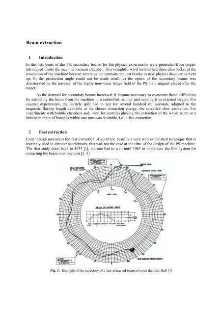
<strong>Beam</strong> <strong>extraction</strong>1 IntroductionIn <strong>the</strong> first years <strong>of</strong> <strong>the</strong> PS, secondary beams for <strong>the</strong> physics experiments were generated from targetsintroduced inside <strong>the</strong> machine vacuum chamber. This straightforward method had three drawbacks: a) <strong>the</strong>irradiation <strong>of</strong> <strong>the</strong> machine became severe as <strong>the</strong> intensity request thanks to new physics discoveries wentup; b) <strong>the</strong> production angle could not be made small; c) <strong>the</strong> optics <strong>of</strong> <strong>the</strong> secondary beams wasdeteriorated by <strong>the</strong> traversal <strong>of</strong> <strong>the</strong> highly non-linear fringe field <strong>of</strong> <strong>the</strong> PS main magnet placed after <strong>the</strong>target.As <strong>the</strong> demand for secondary beams increased, it became necessary to overcome <strong>the</strong>se difficultiesby extracting <strong>the</strong> beam from <strong>the</strong> machine in a controlled manner and sending it to external targets. Forcounter experiments, <strong>the</strong> particle spill had to last for several hundred milliseconds, adapted to <strong>the</strong>magnetic flat-top length available at <strong>the</strong> chosen <strong>extraction</strong> energy, <strong>the</strong> so-called slow <strong>extraction</strong>. Forexperiments with bubble chambers and, later, for neutrino physics, <strong>the</strong> <strong>extraction</strong> <strong>of</strong> <strong>the</strong> whole beam or alimited number <strong>of</strong> bunches within one turn was desirable, i.e., a fast <strong>extraction</strong>.2 Fast <strong>extraction</strong>Even though nowadays <strong>the</strong> fast <strong>extraction</strong> <strong>of</strong> a particle beam is a very well established technique that isroutinely used in circular accelerators, this was not <strong>the</strong> case at <strong>the</strong> time <strong>of</strong> <strong>the</strong> design <strong>of</strong> <strong>the</strong> PS machine.The first study dates back to 1954 [1], but one had to wait until 1963 to implement <strong>the</strong> first system forextracting <strong>the</strong> beam over one turn [2–5].Fig. 1: Example <strong>of</strong> <strong>the</strong> trajectory <strong>of</strong> a fast-extracted beam towards <strong>the</strong> East Hall [4]
high-quality cable used for <strong>the</strong> PFN. The magnet would be a 15 ohm delay-line, installed in machinevacuum using ferrite only as <strong>the</strong> magnet yoke. Interleaved high-grade-finish aluminium alloy plateswould provide <strong>the</strong> needed capacitance, <strong>the</strong> dielectric being <strong>the</strong> machine vacuum. The total system wouldcomprise 12 modules, nine in SS71 and three in SS79 [6].Fig. 2: Left: a module <strong>of</strong> KFA71 or KFA79. Right: Switches for KFA71The initially authorized project was for SS71 only, possibly due to some lingering doubts after <strong>the</strong>failure <strong>of</strong> KFA66. Construction went without surprises and after laboratory testing nine modules wereinstalled in 1973 in SS71. They functioned correctly and were joined a little later by <strong>the</strong> three modules <strong>of</strong>SS79. After 36 years <strong>of</strong> service <strong>the</strong> system is still in use. There have been no high-voltage breakdownsand thyratron switching is trouble-free, average life exceeding 20 000 hours. Overall system availabilityhas been high. After <strong>the</strong> failure <strong>of</strong> KFA66, <strong>the</strong> new version KFA71+KFA79 has been a success.2.2 Extraction septaThe first septum magnet was installed in SS01 in 1963. A first neutrino experiment had been set up in <strong>the</strong>South Hall with <strong>the</strong> <strong>CERN</strong> heavy liquid bubble chamber, a spark chamber experiment, and in <strong>the</strong> end <strong>the</strong>Ecole Polytechnique heavy liquid chamber. The hope was that <strong>CERN</strong> might beat BNL on <strong>the</strong> ‘2neutrinos’ question, but <strong>the</strong>y were faster by a few months.The next operational septum magnet was installed in 1964 in SS58 for <strong>the</strong> East Area bubblechambers. The South-East Area was <strong>the</strong>n specially built for <strong>the</strong> neutrino beam in 1965 and <strong>extraction</strong>from SS74 was installed with hardware transferred from SS01. Then came <strong>the</strong> long septum 16 for<strong>extraction</strong> towards <strong>the</strong> ISR and bubble chambers at <strong>the</strong> end <strong>of</strong> <strong>the</strong> West Area. Since <strong>the</strong> vacuum requiredin <strong>the</strong> PS at that time was not very high, <strong>the</strong> septum yokes were built <strong>of</strong> packets <strong>of</strong> laminations gluedtoge<strong>the</strong>r with Araldite [7].Later on, since lead ions required better vacuum, new models were developed in <strong>the</strong> early 1990swithout organic materials. Standard 0.35 mm thick steel laminations with a 3% silicon content were used,insulated on both sides with an inorganic coating [8].The cooling circuit comprises two thin-walled stainless steel tubes embedded (and brazed) in premachinedslots in <strong>the</strong> septum conductor. This reduces erosion <strong>of</strong> <strong>the</strong> cooling circuit caused by <strong>the</strong> highwater speeds <strong>of</strong> up to 10 m/s.
The tanks are cylindrical, bakeable, and equipped with RF beam screens to insure <strong>the</strong> continuity <strong>of</strong><strong>the</strong> RF impedance. The magnets can be moved remotely in <strong>the</strong> radial and angular directions, while <strong>the</strong>irvacuum tanks remain fixed.For SMH16 (Septum Magnetic Horizontal in SS16, see Fig. 3), <strong>the</strong> maximum field is 1.2 T for apulsed current <strong>of</strong> 28.5 kA. The fringe field measured is less than 1/1000 <strong>of</strong> <strong>the</strong> gap field at a 50 mmdistance from <strong>the</strong> septum conductor.Fig. 3: Extraction septum magnet 16 (photo taken in 1994)These thinly laminated magnets need to be baked out to obtain <strong>the</strong> required vacuum. Thereforeinfra red lamps are installed under vacuum to heat up <strong>the</strong> magnet, while keeping <strong>the</strong> vacuum vessel andvacuum seals at acceptable temperatures. After <strong>the</strong> bake-out cycle, consisting <strong>of</strong> a quasi lineartemperature increase to 200 ºC over 18 hours, a 24-hour flat top at 200 ºC, and an exponentialtemperature decrease <strong>of</strong> approximately 72 hours, a vacuum <strong>of</strong> 6×10 -10 to 4×10 -9 mbar is achieved in <strong>the</strong>tank.3 Slow <strong>extraction</strong>A slow <strong>extraction</strong> over thousands <strong>of</strong> turns obtained by pushing <strong>the</strong> beam away from <strong>the</strong> centre <strong>of</strong><strong>the</strong> vacuum chamber toward a septum magnet would not work. The order <strong>of</strong> magnitude <strong>of</strong> <strong>the</strong> beam sizeis 20 mm and an <strong>extraction</strong> over approximately 200 000 machine revolutions was needed: <strong>the</strong> jump <strong>of</strong>particles per turn at a first septum location would <strong>the</strong>n be 1/10 µm, far less than <strong>the</strong> thinnest feasibleseptum (at <strong>the</strong> PS a 100 µm electrostatic septum is used). In this context, <strong>the</strong> use <strong>of</strong> transverse resonancecan enormously increase this jump, which is also called spiral pitch.
3.1 Integer resonance <strong>extraction</strong>3.1.1 PrincipleThe first use <strong>of</strong> resonances for <strong>extraction</strong> from a particle accelerator dates from <strong>the</strong> early 1950s at <strong>the</strong>University <strong>of</strong> Chicago ‘Fermi’ synchrocyclotron. It was later proposed for <strong>the</strong> first time for a synchrotronin 1961 for <strong>the</strong> PS machine [9, 10]. The scheme was based on integer <strong>extraction</strong>.The radial betatron wavelength <strong>of</strong> <strong>the</strong> machine, which is normally about 6.25, is reduced to 6 byenergizing one or more quadrupoles and some sextupoles. A stable area in <strong>the</strong> transverse phase spaceappears, surrounded by unstable phase space (see Fig. 4). Extraction is achieved by pushing <strong>the</strong> beam out<strong>of</strong> <strong>the</strong> stable area so that particles move away along <strong>the</strong> single separatrix. They are <strong>the</strong>n captured andextracted by a septum magnet. In <strong>the</strong>ory <strong>the</strong> method has a high efficiency and produces an extracted beamwith a small emittance and narrow energy spectrum, without raising any impossible technical problems.Fig. 4: Example <strong>of</strong> typical phase-space diagram for integer resonant slow <strong>extraction</strong>3.1.2 ImplementationThe first tests at <strong>the</strong> PS were conducted in 1964 [11]. The beam was extracted from SS01 (see Fig. 5,left), <strong>the</strong> main, long, straight section used for beams into <strong>the</strong> South experimental hall. Conditions forejection were achieved by pulsing sextupoles in SS25, 55 and 75 with currents <strong>of</strong> one polarity, sextupolesin SS15, 35, 65 and 95 with currents <strong>of</strong> opposite polarity, and also a quadrupole in SS99 located 1/8betatron wave-length upstream from <strong>the</strong> septum magnet at SS01.The septum magnet, designed with a different ejection system in mind had an aperture <strong>of</strong> 28 mmwide by 30 mm high, <strong>the</strong> effective septum thickness being 4.5 mm. From <strong>the</strong> standby position at <strong>the</strong>outside <strong>of</strong> <strong>the</strong> CPS vacuum chamber it was plunged to its working position in about 150 ms.Originally a distance <strong>of</strong> 25 mm between <strong>the</strong> central orbit and <strong>the</strong> nearby edge <strong>of</strong> <strong>the</strong> septum wasspecified. This was changed afterwards to 20 mm (Fig. 5, right). The 5 kA power supply, a six phasemercury vapour rectifier, produced a field ripple <strong>of</strong> several per cent, <strong>the</strong> exact value depending on <strong>the</strong>particular current pulse used. This ripple could be reduced by an order <strong>of</strong> magnitude through insertion <strong>of</strong> a9 mH choke <strong>of</strong> low resistance (a spare CPS magnet unit, no. 102) in <strong>the</strong> circuit. However, as <strong>the</strong> coolingcapacity <strong>of</strong> <strong>the</strong> septum magnet was limited, <strong>the</strong> longer current rise-time produced by <strong>the</strong> choke led to a
<strong>the</strong> semi-quadrupole began to raise problems and it was exchanged for a quadrupole and two sextupoleswhich gave about <strong>the</strong> same effect so that <strong>the</strong> <strong>extraction</strong> performance was not altered.3.3 Third-integer resonance SE61 <strong>extraction</strong>3.3.1 Reasons for a new <strong>extraction</strong> system and its principleIn <strong>the</strong> late 1980s, <strong>the</strong> requirements for slow <strong>extraction</strong> had changed:– There was no more <strong>extraction</strong> towards <strong>the</strong> West Hall.– There were no more internal targets.– The PS was accelerating leptons for LEP on certain cycles and <strong>the</strong> electrostatic and even <strong>the</strong>magnetic septa placed towards <strong>the</strong> outside <strong>of</strong> <strong>the</strong> machine orbit suffered from synchrotronradiation during <strong>the</strong>re cycles– It was desirable to have fewer septa to save space in <strong>the</strong> machine and reduce <strong>the</strong> maintenanceeffort.– Better vacuum was necessary to prepare for ions, so that organic material was banished invacuum.– The septum magnets had aged.– The systematic losses on magnetic septa were excessive.A new <strong>extraction</strong> scheme was developed to fit <strong>the</strong>se requirements and benefit from <strong>the</strong> lessstringent specifications (no more West Hall and internal targets) [15–17]. Its main characteristics are:– Protection <strong>of</strong> <strong>the</strong> septa from synchrotron radiation during lepton cycles since <strong>the</strong>y are placedtowards <strong>the</strong> inside <strong>of</strong> <strong>the</strong> machine or are outside vacuum.– Reduced number <strong>of</strong> septa for less maintenance (only one septum magnet in vacuum instead <strong>of</strong>three before).– Improved vacuum (required for ion acceleration): <strong>the</strong> thin septum magnet can be baked out, <strong>the</strong>tank is made <strong>of</strong> vacuum fired 316LN stainless steel, and <strong>the</strong>re is no organic material in vacuum.– Systematic losses due to chromatic effects at <strong>the</strong> thin septum magnet are avoided throughadjustment <strong>of</strong> local dispersion coefficients at <strong>the</strong> electrostatic and thin magnetic septa.3.3.2 Layout <strong>of</strong> SE61The new <strong>extraction</strong> was commissioned in March 1992 and regular operation could start immediately [18].The elements installed in <strong>the</strong> PS machine are (Fig. 10):
– Quadrupoles (in SS29 and SS87) to raise Q hfrom 6.2 to 6.33, increase hat <strong>the</strong> septa, anddecrease <strong>the</strong> horizontal dispersion at <strong>the</strong> electrostatic septum and increase it at <strong>the</strong> first magneticseptum.– Sextupoles (one in SS7 and two in SS19) to provide <strong>the</strong> 19th harmonic defining <strong>the</strong> stable andunstable phase areas, and <strong>the</strong> zero harmonic to decrease <strong>the</strong> horizontal chromaticity | h|.– One electrostatic septum in SS23 on <strong>the</strong> machine centre side (Fig. 11, left).– One magnetic septum in SS57 under vacuum on <strong>the</strong> machine centre side (<strong>the</strong> only magneticseptum under vacuum) (Fig. 11, right).– One magnetic septum in SS61 outside vacuum (Fig. 12, left).– Bumpers in SS19 and 27 to approach <strong>the</strong> electrostatic septum.– Bumpers in SS53, 59, 61 (septum type, Fig. 12, right) and 67 to approach <strong>the</strong> beam to bothmagnetic septa.D53EXTRACTOR SEPTUMMAGNET 61D59FIRSTSEPTUMMAGNET 57D61(septum)D67D27QUADRUPOLE 29<strong>CERN</strong> PS SLOWEXTRACTIONELECTROSTATICSEPTUM 23QUADRUPOLE 87D19SEXTUPOLE 19SEXTUPOLE 7Fig. 10: Layout <strong>of</strong> <strong>the</strong> elements for SE61
Fig. 11: Left: electrostatic septum in SS23. Right: <strong>the</strong> thin septum in its tank.In 2007, <strong>the</strong> sextupoles in SS19 had to be displaced to free <strong>the</strong> straight section in conjunction with<strong>the</strong> installation <strong>of</strong> <strong>the</strong> multi-turn <strong>extraction</strong> (MTE). They were first placed in SS03 but it turned out that<strong>the</strong> separatrices were curved and that <strong>the</strong> efficiency was lowered and losses increased (paren<strong>the</strong>tically, <strong>the</strong>initial performance was restored by using octupole magnets to re-shape <strong>the</strong> separatrices at largeamplitude). Never<strong>the</strong>less, to ease operation, it was decided to find a better place for <strong>the</strong> sextupoles, whichwere <strong>the</strong>n moved again to SS01 and <strong>the</strong> efficiency returned to its previous value.Fig. 12: Left: <strong>the</strong> <strong>extraction</strong> septum in SS61. Right: <strong>the</strong> septum bumper in SS61.The phase plane plots at <strong>the</strong> electrostatic septum 23 (Fig. 13, left) and thin septum 57 (Fig. 13,right) show <strong>the</strong> main difference with <strong>the</strong> Square <strong>extraction</strong>. The improvement <strong>of</strong> <strong>the</strong> systematic losses on<strong>the</strong> first magnetic septum (thin septum) is obvious when <strong>the</strong> plots at <strong>the</strong> thin septa are compared (Fig. 9,right and Fig. 13, right). By a proper choice <strong>of</strong> <strong>the</strong> horizontal dispersion at <strong>the</strong> electrostatic septum and at<strong>the</strong> first magnetic septum, <strong>the</strong> separation between ejected and circulating beam was enlarged, <strong>the</strong>magnetic septum thickness could be enlarged, resulting in a welcome increase <strong>of</strong> its deflection angle.Therefore only one extractor magnet was needed and it could even be installed outside <strong>the</strong> vacuumenclosure.
Fig. 13: Left: phase space plot at ES23. Right: phase space plot at TSM57.The de-bunching is kept unchanged from <strong>the</strong> Square <strong>extraction</strong>. When <strong>the</strong> beam reaches <strong>the</strong> flattop, <strong>the</strong> radial position is changed, using an <strong>of</strong>fset on <strong>the</strong> beam control radial loop, so as to place <strong>the</strong> beamjust outside <strong>the</strong> resonance. In order to suppress <strong>the</strong> RF component in <strong>the</strong> spill and enlarge p/p (to lower<strong>the</strong> effect <strong>of</strong> <strong>the</strong> low frequency ripple), de-bunching is <strong>the</strong>n done as seen on Fig. 14. Starting from <strong>the</strong>stable beam in longitudinal phase space (a), <strong>the</strong> RF phase is changed by 180 o during about 500 s so thatbunches stretch along separatrices (b), <strong>the</strong>n <strong>the</strong> phase is changed back to <strong>the</strong> initial value (c) so thatbunches rotate during about 3 ms after which <strong>the</strong> RF power is turned <strong>of</strong>f and cavities are short-circuited(d). A careful tune <strong>of</strong> <strong>the</strong>se parameters results in a nearly homogeneous distribution <strong>of</strong> p/p and <strong>the</strong>reforea regular spill with almost rectangular shape versus time.Fig. 14: The RF gymnastic for de-bunching
3.3.3 Performance <strong>of</strong> <strong>the</strong> SE61 <strong>extraction</strong>Owing to East Area radiation limitations, <strong>the</strong> intensity is restricted to 2×10 11 protons per pulse (ppp) pereach <strong>of</strong> <strong>the</strong> two external targets. The particle momentum is 24 GeV/c in normal operation, but o<strong>the</strong>renergies are also possible. When carefully adjusted, <strong>the</strong> efficiency can reach values above 95%. Lossesare practically limited to <strong>the</strong> electrostatic septum straight section. For a 3×10 11 ppp beam, <strong>the</strong> typicalphysical emittance <strong>of</strong> <strong>the</strong> extracted beam is 0.1 rad in <strong>the</strong> horizontal plane and 0.8 rad in <strong>the</strong>vertical plane. The instantaneous momentum spread p/p is 0.08% and <strong>the</strong> total p/p is 0.3%. Themaximum spill length is 500 ms, <strong>the</strong> standard value being 400 ms.3.3.4 Ripple correctionThe residual undulation on <strong>the</strong> power supplies was responsible for a ripple in Q h which induced a ripple in<strong>the</strong> extracted beam intensity. The frequencies were usually 100, 300 and 600 Hz. Physicists <strong>of</strong>ten requireda cure for <strong>the</strong>se intensity fluctuations.A servo-system had already been used with <strong>the</strong> Square <strong>extraction</strong> to overcome this problem. Amonitor in <strong>the</strong> extracted beam gives <strong>the</strong> intensity <strong>of</strong> <strong>the</strong> spill. It is compared with a fixed reference, <strong>the</strong>difference undergoes various corrections through filters and it is fed through a wide-band power amplifierto a quadrupole. Only <strong>the</strong> lower frequencies could be corrected this way owing to <strong>the</strong> slow response <strong>of</strong> <strong>the</strong><strong>extraction</strong> to a change in Q h . This is due to <strong>the</strong> great number <strong>of</strong> revolutions in <strong>the</strong> machine before aparticle is ejected.Ano<strong>the</strong>r, more successful way to correct <strong>the</strong> low frequency ripple is <strong>the</strong> feed-forward method, asshown in Fig. 15.Fig. 15: Left: spill and circulating current without correction (1997). Right: spill(PE.MLSDSESPILL) and circulating (PE.TRA345E11) current after correction <strong>of</strong> <strong>the</strong> mainsharmonics 2, 3, 4, 6, 8, 12 <strong>of</strong> 50 Hz.An air quadrupole is installed in <strong>the</strong> machine at a high h location. An audio-frequency amplifierfeeds it with <strong>the</strong> harmonics to be corrected. They are syn<strong>the</strong>sized with a function generator, synchronizedwith <strong>the</strong> mains, variable in phase and amplitude. The optimization was done manually, optimizing <strong>the</strong>Fourier transform from cycle to cycle. This was a long process, since 7 frequencies were involved: 50,100, 150, 200, 300, 400 and 600 Hz. The optimization had to be performed from time to time because <strong>of</strong>ageing and detuning <strong>of</strong> <strong>the</strong> various power supplies or changes in mains phase.A third possibility is <strong>the</strong> phase displacement (empty bucket channelling) method [19]. The beam isdisplaced away from <strong>the</strong> resonance and <strong>the</strong>n de-bunched. RF cavities are excited at a harmonic <strong>of</strong> <strong>the</strong>revolution frequency corresponding to <strong>the</strong> position <strong>of</strong> <strong>the</strong> resonance. This increases dQ/dt <strong>of</strong> <strong>the</strong> particleswhich squeeze in between <strong>the</strong> empty buckets, and thus decreases efficiently <strong>the</strong> low-frequency ripple(Fig. 16). The latter is traded against a strong RF component. This method was tested experimentally only
with 200 MHz cavities but was not put into operation since <strong>the</strong> RF cavities were not available in normaloperation.EAmplitudeResonanceregionResonance linefor low betatronamplitudesSense <strong>of</strong> stackaccelerationResonance linefor high betatronamplitudesFig. 16: Longitudinal phase space diagram channelling around empty moving bucketPHASENowadays, <strong>the</strong> regulation <strong>of</strong> <strong>the</strong> power supplies for <strong>the</strong> main magnets as well as for <strong>the</strong> pole facewindings has made such progress that <strong>the</strong>ir residual ripples have become quite negligible. All <strong>the</strong>secompensation systems are <strong>the</strong>refore no longer in operation.All in all, slow <strong>extraction</strong> has been provided to <strong>the</strong> <strong>CERN</strong> PS physicist clients for 45 years. Therewas a time when a good part <strong>of</strong> <strong>the</strong> relevant physics research was performed on secondary beams fromexternal targets fed this way and sometimes even directly on <strong>the</strong> extracted protons. Nowadays <strong>the</strong>emphasis is on colliding beams, but slow <strong>extraction</strong> in <strong>the</strong> East Area <strong>of</strong> <strong>the</strong> <strong>CERN</strong> PS is still busy withtests on <strong>the</strong> various types <strong>of</strong> equipment for LHC physics, and some interesting experiments such asDIRAC studying <strong>the</strong> strong force and CLOUDS which will investigate <strong>the</strong> possible influence <strong>of</strong> galacticcosmic rays on <strong>the</strong> Earth’s clouds and climate.4 Continuous Transfer or CT <strong>extraction</strong>This original <strong>extraction</strong> method was driven by <strong>the</strong> need to fill <strong>the</strong> <strong>CERN</strong> SPS as uniformly as possible[20–27]. The SPS circumference is eleven times that <strong>of</strong> <strong>the</strong> PS, hence <strong>the</strong> SPS could be filled byextracting <strong>the</strong> beam over several turns from <strong>the</strong> PS machine.Such an approach would leng<strong>the</strong>n <strong>the</strong> duration <strong>of</strong> <strong>the</strong> beam, but it would also provide a natural way<strong>of</strong> manipulating <strong>the</strong> transverse emittance <strong>of</strong> <strong>the</strong> extracted beam. This is certainly an interesting feature forovercoming potential aperture bottlenecks in <strong>the</strong> receiving machine.The principle itself [20–24] is based on a careful choice <strong>of</strong> <strong>the</strong> horizontal tune <strong>of</strong> <strong>the</strong> PS machineand on a variable-strength closed bump. On a turn-by-turn basis <strong>the</strong> beam is pushed towards anelectrostatic septum: <strong>the</strong> beam in <strong>the</strong> septum gap will be deflected and will oscillate around a fraction <strong>of</strong><strong>the</strong> machine circumference. A magnetic septum will <strong>the</strong>n provide <strong>the</strong> necessary deflection for <strong>the</strong> beam toleave <strong>the</strong> machine and enter <strong>the</strong> transfer line.
After <strong>the</strong> proposal, an experimental test was set up [25]. In order to re-use a maximum <strong>of</strong> existingequipment, <strong>the</strong> layout <strong>of</strong> <strong>the</strong> slow bump used to approach <strong>the</strong> electrostatic septum and <strong>the</strong> fast bump toshave <strong>the</strong> beam was not that <strong>of</strong> <strong>the</strong> operational configuration. The test layout is shown in Fig. 17.Fig. 17: Sketch <strong>of</strong> <strong>the</strong> experimental set-up for <strong>the</strong> first tests with an eleven-turn CT <strong>extraction</strong> (fromRef. [25])The initial tests provided an extracted beam at 10 GeV/c over ten or eleven turns. The latter case isshown in Fig. 18 where <strong>the</strong> circulating intensity, <strong>the</strong> extracted intensity, and <strong>the</strong> strength <strong>of</strong> <strong>the</strong> staircasekicker are reported.The longitudinal structure <strong>of</strong> <strong>the</strong> beam has no impact on <strong>the</strong> <strong>extraction</strong> proper, only <strong>the</strong> losses at<strong>extraction</strong> being different due to <strong>the</strong> finite rise time <strong>of</strong> <strong>the</strong> kickers used to generate <strong>the</strong> fast bump. Bothbunched and de-bunched beams were considered during <strong>the</strong> ejection tests reported in Ref. [25].Of course, <strong>the</strong> eleven-turn <strong>extraction</strong> was not adapted to <strong>the</strong> injection in <strong>the</strong> proposed SPS, as <strong>the</strong>rewas no place to accommodate <strong>the</strong> rise time <strong>of</strong> <strong>the</strong> injection kicker. Therefore, <strong>the</strong> ten-turn version became<strong>the</strong> nominal configuration for a while [26], typically for intensities up to about 7×10 12 protons. Already atthat time it became clear that for higher intensity operations, a new variant was needed providing moreprotons. In fact, <strong>the</strong> solution found, and in operation to date, is <strong>the</strong> filling <strong>of</strong> <strong>the</strong> SPS by means <strong>of</strong> twoconsecutive PS <strong>extraction</strong>s over five turns. In addition, <strong>the</strong> <strong>extraction</strong> energy was increased to 14 GeV/c.The layout <strong>of</strong> <strong>the</strong> hardware required and installed in <strong>the</strong> PS ring is shown in Fig. 19 from Ref. [25], where<strong>the</strong> issue <strong>of</strong> controlling <strong>the</strong> overall <strong>extraction</strong> system is addressed in detail.Fig. 18: Experimental results <strong>of</strong> <strong>the</strong> setting up <strong>of</strong> an eleven-turn CT <strong>extraction</strong> from Ref. [25]. Thecirculating intensity (left), <strong>the</strong> extracted intensity (centre), and <strong>the</strong> staircase current (right) are shown.In <strong>the</strong> latter scheme <strong>the</strong> horizontal tune <strong>of</strong> <strong>the</strong> PS machine is set to <strong>the</strong> value 6.25 just prior to<strong>extraction</strong>. At <strong>the</strong> same time <strong>the</strong> closed-orbit is modified by means <strong>of</strong> two dipoles that generate a closedbump around <strong>the</strong> electrostatic septum located in section 31 <strong>of</strong> <strong>the</strong> PS circumference. In addition, a secondbump centred on <strong>the</strong> electrostatic septum is generated by two kickers so that by selecting its amplitude, adifferent portion <strong>of</strong> <strong>the</strong> beam is cut <strong>of</strong>f. Because <strong>of</strong> <strong>the</strong> value <strong>of</strong> <strong>the</strong> horizontal tune, four slices are shaved
<strong>of</strong>f and extracted as a continuous ribbon over four turns. Therefore, only a fraction <strong>of</strong> <strong>the</strong> beam coreremains in <strong>the</strong> machine and is extracted last, during <strong>the</strong> fifth turn, by changing <strong>the</strong> beam trajectory, so asto jump over <strong>the</strong> septum blade. This shaved beam receives a horizontal kick by <strong>the</strong> electrostatic septumthat produces <strong>the</strong> necessary displacement to jump over <strong>the</strong> thicker blade <strong>of</strong> <strong>the</strong> magnetic septum located insection 16 <strong>of</strong> <strong>the</strong> PS ring (see Fig. 19).Fig. 19: Sketch <strong>of</strong> <strong>the</strong> CT <strong>extraction</strong> from Ref. [27]To amplify <strong>the</strong> effect <strong>of</strong> <strong>the</strong> kickers and septa on <strong>the</strong> beam trajectory, <strong>the</strong> optics <strong>of</strong> <strong>the</strong> machine isperturbed by means <strong>of</strong> <strong>the</strong> so-called kick enhancement quadrupoles (QKE16), namely two quadrupoleslocated in SS05 and SS25, as can be seen in Fig. 20 (top). They increase <strong>the</strong> horizontal beta-function at<strong>the</strong> location <strong>of</strong> <strong>the</strong> electrostatic septum so as to reduce <strong>the</strong> local beam density and hence <strong>the</strong> losses on <strong>the</strong>device. At <strong>the</strong> same time, <strong>the</strong> value <strong>of</strong> <strong>the</strong> horizontal dispersion function is reduced at <strong>the</strong> electrostaticseptum, thus making <strong>the</strong> whole <strong>extraction</strong> process less sensitive to <strong>the</strong> intrinsic momentum spread <strong>of</strong> <strong>the</strong>beam. In 2007, during a campaign <strong>of</strong> <strong>extraction</strong> loss studies, <strong>the</strong> quadrupoles in SS05 were displaced toSS73. The new optics, shown in Fig. 20 (bottom), displaced <strong>the</strong> losses produced by particles scattered by<strong>the</strong> electrostatic septum in better shielded zones <strong>of</strong> <strong>the</strong> tunnel.From <strong>the</strong> principle it is clear that <strong>the</strong> five extracted slices have different <strong>extraction</strong> conditions, i.e.,positions and angles at <strong>extraction</strong> and have different shapes and emittances in transverse phase space.During normal operation, <strong>the</strong> difference in <strong>extraction</strong> trajectories is corrected by means <strong>of</strong> dedicatedkickers installed in <strong>the</strong> TT2 transfer line, <strong>the</strong> DFAs, also called Emittance Reduction Dipoles (ERDs). Itwas already mentioned that one <strong>of</strong> <strong>the</strong> aims <strong>of</strong> CT <strong>extraction</strong> is to reduce <strong>the</strong> extracted beam emittance.Never<strong>the</strong>less, it is worth noting that <strong>the</strong> <strong>extraction</strong> shaving occurs in <strong>the</strong> horizontal plane, while <strong>the</strong>aperture limitation in <strong>the</strong> SPS is mainly in <strong>the</strong> vertical plane. Therefore, a special optics insertion wasadded in <strong>the</strong> TT10 part <strong>of</strong> <strong>the</strong> PS–SPS transfer line in order to exchange <strong>the</strong> transverse plane and henceincrease <strong>the</strong> usefulness <strong>of</strong> <strong>the</strong> emittance reduction [28].
807060 x yD xSS315040SS05SS253020100-100 5 10 15 20 25 30 35 40 45 50 55 60 65 70 75 80 85 90 95 100Straight Section807060 x yD x5040SS25SS733020100-100 5 10 15 20 25 30 35 40 45 50 55 60 65 70 75 80 85 90 95 100Straight SectionFig. 20: Optical parameters for <strong>the</strong> PS ring when <strong>the</strong> beam is sliced for CT. The standard optics isperturbed by means <strong>of</strong> special quadrupoles, <strong>the</strong> QKE16 (top, original <strong>extraction</strong> optics, bottom, opticsused for <strong>the</strong> loss displacement).A typical time pr<strong>of</strong>ile <strong>of</strong> <strong>the</strong> CT ejection is shown in Fig. 21, from <strong>the</strong> 2008 SPS physics run. Theintensity is measured at injection in <strong>the</strong> SPS by means <strong>of</strong> a fast beam current transformer. The firstinjected batch (left part) remained in <strong>the</strong> machine for 1.2 s while waiting for <strong>the</strong> second batch.It is clear, however, that a number <strong>of</strong> drawbacks are present, namely: i) beam losses, especially at<strong>the</strong> electrostatic septum, are unavoidable. They amount to about 10–15% <strong>of</strong> <strong>the</strong> total beam intensity; ii)<strong>the</strong> extracted slices do not match <strong>the</strong> natural structure (circles) in normalized horizontal phase-space, thusgenerating a betatronic mismatch. This, in turn, induces emittance blow-up in <strong>the</strong> receiving machine; iii)<strong>the</strong> extracted slices have different horizontal transverse emittance. A detailed analysis <strong>of</strong> <strong>the</strong> properties <strong>of</strong><strong>the</strong> extracted slices can be found in Ref. [29], where computation <strong>of</strong> <strong>the</strong> mismatch parameters for <strong>the</strong> CTas a function <strong>of</strong> <strong>the</strong> slicing was performed. For <strong>the</strong> CT <strong>extraction</strong>, <strong>the</strong> optical parameters and <strong>the</strong> beamemittance are different for <strong>the</strong> five slices, thus generating different emittance blow-up at SPS injection.Fur<strong>the</strong>rmore, because <strong>of</strong> <strong>the</strong> fancy shape <strong>of</strong> <strong>the</strong> slices, <strong>the</strong> mismatch can be ra<strong>the</strong>r large.The optical properties <strong>of</strong> <strong>the</strong> five extracted slices <strong>of</strong> <strong>the</strong> CT can be derived by performingintegration over <strong>the</strong> beam distribution taking into account <strong>the</strong> shape <strong>of</strong> <strong>the</strong> slice due to <strong>the</strong> interaction with<strong>the</strong> electrostatic septum. Knowing that <strong>the</strong> relative position between <strong>the</strong> septum and <strong>the</strong> beam can becontrolled on a turn-by-turn basis, it is ra<strong>the</strong>r straightforward to compute all relevant quantities for eachslice (in some cases it is even possible to derive analytical expressions <strong>of</strong> <strong>the</strong> optical parameters vs. <strong>the</strong>septum position). Two approaches have been followed, corresponding to <strong>the</strong> equalization <strong>of</strong> <strong>the</strong> beamintensity or <strong>of</strong> <strong>the</strong> extracted emittance. The first approach corresponds to what is done in reality when
tuning <strong>the</strong> beam. The second one cannot be applied in practice on account <strong>of</strong> lack <strong>of</strong> an appropriateinstrument to measure <strong>the</strong> beam emittance <strong>of</strong> each extracted slice.5.04.54.03.5Intensity (10 10 p)3.02.52.01.51.00.50.00 5 10 15 20 25Time (ms)Fig. 21: The two-batch injection in <strong>the</strong> SPS using a five-turn CT <strong>extraction</strong> from <strong>the</strong> PS. The beamintensity is measured with a SPS fast beam current transformer. The width <strong>of</strong> <strong>the</strong> line is due to <strong>the</strong>overlay over seven injections. The beam is <strong>the</strong>n accelerated and extracted towards <strong>the</strong> CNGS target.As expected, it turns out that <strong>the</strong> two approaches are not compatible with each o<strong>the</strong>r. In o<strong>the</strong>rwords, making <strong>the</strong> intensity equal generates very unequal emittances and vice versa. This fact isvisualized in Fig. 22, where <strong>the</strong> shape <strong>of</strong> <strong>the</strong> five slices is shown for <strong>the</strong> two approaches. The difference isclearly visible.443322110-4 -3 -2 -1 0 1 2 3 4-10-4 -3 -2 -1 0 1 2 3 4-1-2-2-3-3-4-4Fig. 22: Shape <strong>of</strong> <strong>the</strong> five slices for <strong>the</strong> present CT in normalized phase space (x, x’) according towhe<strong>the</strong>r intensities (left) or emittances (right) have been equalized. The solid circle has a radius <strong>of</strong>14where is <strong>the</strong> r.m.s. beam emittance before slicing.5 Why replace <strong>the</strong> CT?In <strong>the</strong> framework <strong>of</strong> <strong>the</strong> activities to prepare <strong>the</strong> future high-intensity proton beam for <strong>the</strong> <strong>CERN</strong> Neutrinoto Gran Sasso (CNGS) Project [30], a critical review <strong>of</strong> <strong>the</strong> key processes used to generate such a beamwas carried out [31], in view <strong>of</strong> a possible upgrade beyond <strong>the</strong> present nominal intensity value <strong>of</strong> about
3.3×10 13 protons per PS batch. Among o<strong>the</strong>r issues, efforts were devoted to <strong>the</strong> improvement <strong>of</strong> <strong>the</strong>present <strong>extraction</strong> scheme from <strong>the</strong> PS to <strong>the</strong> SPS, <strong>the</strong> Continuous Transfer.In <strong>the</strong> framework <strong>of</strong> <strong>the</strong> High Intensity <strong>Proton</strong>s Working Group (HIP-WG) [32] a detailed analysis<strong>of</strong> <strong>the</strong> losses for <strong>the</strong> beam for CNGS was performed [33]. The outcome is ra<strong>the</strong>r striking: for an overallintensity <strong>of</strong> about 4.5×10 19 protons/year required by <strong>the</strong> neutrino experiments, approximately 1.7×10 19 arelost in <strong>the</strong> accelerator chain, corresponding to about 40% <strong>of</strong> <strong>the</strong> total intensity. A large fraction <strong>of</strong> beamlosses, namely 0.7×10 19 , or 40% <strong>of</strong> <strong>the</strong> total intensity lost occurs in <strong>the</strong> electrostatic septum <strong>of</strong> <strong>the</strong> PS ringused to slice <strong>the</strong> beam.In <strong>the</strong> quest for an improved <strong>extraction</strong> mode, a novel approach was proposed, named multi-turn<strong>extraction</strong> (MTE). In <strong>the</strong> new scenario <strong>the</strong> beam is separated in transverse phase space by generatingstable islands inside <strong>the</strong> region where <strong>the</strong> beam sits and by slowly (adiabatically) moving <strong>the</strong>m towardshigher amplitudes. By doing this, particles may get trapped inside islands thus generating well-separatedbeamlets [34]. This method is potentially superior to <strong>the</strong> present one as no intercepting device is used tosplit <strong>the</strong> beam; hence particle losses are limited to <strong>the</strong> fraction <strong>of</strong> <strong>the</strong> beam improperly deflected during<strong>the</strong> kicker rise time. Fur<strong>the</strong>rmore, <strong>the</strong> extracted beam should better match <strong>the</strong> phase space structure.6 Novel Multi-Turn Extraction6.1 PrincipleThe novel technique relies on <strong>the</strong> use <strong>of</strong> non-linear magnetic fields (sextupolar and octupolar) to generatestable islands in <strong>the</strong> horizontal phase space [35]. By means <strong>of</strong> an appropriate tune variation, a specificresonance is crossed, <strong>the</strong> fourth-order in <strong>the</strong> case under study, and <strong>the</strong> beam is split by trapping inside <strong>the</strong>stable islands moving from <strong>the</strong> origin <strong>of</strong> <strong>the</strong> phase space towards higher amplitudes [34]. A good modelconsists in choosing a simple FODO cell with a sextupole and an octupole located at <strong>the</strong> samelongitudinal position, both represented in <strong>the</strong> single-kick approximation [36]. An example <strong>of</strong> <strong>the</strong> change<strong>of</strong> <strong>the</strong> phase space topology during resonance crossing is shown in Fig. 23.1(a)1(b)1(c)X’X’X’-1-1 X1-1-1 X1-1-1 X1Fig. 23: Topology <strong>of</strong> <strong>the</strong> normalized phase space during resonance crossingThe evolution <strong>of</strong> <strong>the</strong> beam distribution during <strong>the</strong> resonance crossing is shown in Fig. 24.
Fig. 24: Evolution <strong>of</strong> <strong>the</strong> beam distribution during resonance crossing. The initial state is representedby a bi-Gaussian beam (left), at resonance crossing some particles are trapped inside <strong>the</strong> movingislands (centre), at <strong>the</strong> end <strong>of</strong> <strong>the</strong> process, <strong>the</strong> particles trapped in <strong>the</strong> islands are moved towards higheramplitudes (right).When <strong>the</strong> tune is changed, <strong>the</strong> islands move through <strong>the</strong> phase space region where <strong>the</strong> chargedparticles sit and some are trapped inside <strong>the</strong> islands. At some stage a complete separation between <strong>the</strong>beamlets and <strong>the</strong> central core occurs and <strong>the</strong> distance between <strong>the</strong> beamlets can be increased at will bysimply acting on <strong>the</strong> tune. It is worth while stressing that <strong>the</strong> beam after trapping has a peculiar structure,i.e., it is made <strong>of</strong> two disconnected parts: <strong>the</strong> beamlets, which are indeed one single structure closing upafter four turns around <strong>the</strong> machine (see Fig. 25), and <strong>the</strong> central core.The idea behind this process is that such a beam splitting in <strong>the</strong> transverse phase space can be usedto perform multi-turn <strong>extraction</strong>. In fact, once <strong>the</strong> various beamlets are separated, <strong>the</strong> whole structure canbe pushed towards an <strong>extraction</strong> septum by means <strong>of</strong> a closed slow bump. Then, kicker magnets generatea fast closed bump and one island jumps beyond <strong>the</strong> septum blade so that <strong>the</strong> beamlets are extracted out<strong>of</strong> <strong>the</strong> machine in four turns. The fifth beamlet, i.e., <strong>the</strong> beam core, is extracted using a classical singleturn<strong>extraction</strong>. The advantage <strong>of</strong> this approach is that, at least for <strong>the</strong> first four turns, <strong>the</strong> opticalparameters are, by definition, <strong>the</strong> same. This is intrinsic to <strong>the</strong> method, as <strong>the</strong> same stable island is used toextract <strong>the</strong> beam.It is worth stressing that numerical simulations are performed by crossing <strong>the</strong> resonance fromabove: this is <strong>the</strong> opposite <strong>of</strong> what is done in <strong>the</strong> experimental tests, where <strong>the</strong> resonance is crossed frombelow. The choice <strong>of</strong> <strong>the</strong> resonance to be crossed is completely arbitrary as <strong>the</strong> use <strong>of</strong> a fourth-orderresonance is dictated only by <strong>the</strong> <strong>CERN</strong>-specific application (see Refs. [37, 38] for a generalization too<strong>the</strong>r types <strong>of</strong> resonance and to injection, respectively).6.2 Measurement results6.2.1 Overall measurement strategyIn parallel with <strong>the</strong> computational and <strong>the</strong>oretical analysis, an intense experimental campaign waslaunched at <strong>the</strong> end <strong>of</strong> 2001 on <strong>the</strong> <strong>CERN</strong> PS (see Ref. [39] for <strong>the</strong> final account <strong>of</strong> <strong>the</strong> results achieved).This entailed <strong>the</strong> development <strong>of</strong> new measurement systems, such as <strong>the</strong> turn-by-turn orbit measurementsystem [40, 41], as well as <strong>the</strong> installation <strong>of</strong> sextupoles and octupoles to generate <strong>the</strong> stable islands.
Fig. 25: 3D view <strong>of</strong> <strong>the</strong> beamlets along <strong>the</strong> circumference <strong>of</strong> <strong>the</strong> PS machine. The fifth beamlet, i.e.,<strong>the</strong> beam core, is not shown here.The magnetic elements and <strong>the</strong> beam instrumentation used in <strong>the</strong> experimental campaign are shownin Fig. 26 (left). The tune is changed by means <strong>of</strong> <strong>the</strong> two families <strong>of</strong> focusing and defocusingquadrupoles, normally used to control <strong>the</strong> machine at low energy. Sextupoles and octupoles are used togenerate <strong>the</strong> stable islands; <strong>the</strong> fast-<strong>extraction</strong> kicker is used to displace <strong>the</strong> beam and induce betatronoscillations for phase space measurements; a wire scanner [42] is used to measure <strong>the</strong> horizontal beampr<strong>of</strong>ile (see Fig. 26 – right – for details on <strong>the</strong> installation); two pick-ups are used to record <strong>the</strong> betatronoscillations.Trapping measurements with a high-intensity beam represented <strong>the</strong> most important test for thisnovel approach. A sequence <strong>of</strong> transverse beam pr<strong>of</strong>iles during <strong>the</strong> splitting process is shown in Fig. 27(upper part) toge<strong>the</strong>r with <strong>the</strong> best result achieved (lower part). The intensity as a function <strong>of</strong> time isshown (lower left). The injected intensity is slightly above 6×10 12 protons and small losses are visible upto transition crossing (second vertical red line). Then, <strong>the</strong> intensity stays remarkably constant up to<strong>extraction</strong>, which is performed by means <strong>of</strong> a kicker in a single turn after having merged back <strong>the</strong>beamlets in order to reduce <strong>the</strong> beam size in <strong>the</strong> horizontal plane to match <strong>the</strong> septum acceptance. Thebeam distribution as measured in <strong>the</strong> transfer line downstream <strong>of</strong> <strong>the</strong> <strong>extraction</strong> point from <strong>the</strong> PSmachine is shown in Fig. 27 (lower right). Optical Transition Radiation (OTR) [43] is used to record <strong>the</strong>two-dimensional beam distribution in physical space. The peculiar shape <strong>of</strong> <strong>the</strong> beam distribution isclearly visible: <strong>the</strong> two lateral peaks represent <strong>the</strong> projection in physical space <strong>of</strong> <strong>the</strong> beamlets.A final test was performed to increase <strong>the</strong> fraction <strong>of</strong> particles trapped inside <strong>the</strong> islands. For thisstudy, a special setting <strong>of</strong> <strong>the</strong> octupoles was programmed: instead <strong>of</strong> keeping <strong>the</strong>ir strength constant allalong <strong>the</strong> resonance-crossing phase, <strong>the</strong> current was suddenly increased just before resonance crossingand <strong>the</strong>n gradually reduced. This should generate large islands at small amplitudes thus trapping moreparticles from <strong>the</strong> region where <strong>the</strong> density is high, and <strong>the</strong>n keeping almost constant <strong>the</strong> island’s size.The results are shown in Fig. 28, where <strong>the</strong> current as a function <strong>of</strong> time for both <strong>the</strong> sextupoles and <strong>the</strong>octupoles is shown (left) as well as <strong>the</strong> measured horizontal beam pr<strong>of</strong>ile (right).
Section 54Section 55Section 21Section 20Extraction lineFlying wiresSextupole magnetsKicker magnetOctupole magnetsSlow bumpExtractionseptumSection 16Section 64Section 71Fig. 26: Schematic layout <strong>of</strong> <strong>the</strong> PS machine with <strong>the</strong> elements used for <strong>the</strong> experimental study <strong>of</strong> <strong>the</strong>novel multi-turn <strong>extraction</strong> (left). Schematic layout <strong>of</strong> <strong>the</strong> mechanism <strong>of</strong> <strong>the</strong> PS wire scanner (upperright). The installation <strong>of</strong> <strong>the</strong> scintillators on both sides <strong>of</strong> <strong>the</strong> vacuum pipe is also shown (lowerright).Under <strong>the</strong>se new conditions it was indeed possible to increase <strong>the</strong> fraction <strong>of</strong> particles inside <strong>the</strong>islands, achieving a value <strong>of</strong> 18% against a previous value <strong>of</strong> about 13%. It is worth while mentioningthat for <strong>the</strong> optimal performance <strong>of</strong> <strong>the</strong> SPS machine, <strong>the</strong> tolerance for <strong>the</strong> fraction <strong>of</strong> particles in eachbeamlet is (20±5)%. Therefore, if this needs to hold for <strong>the</strong> central core, <strong>the</strong>n, <strong>the</strong> four beamlets shouldsatisfy <strong>the</strong> tighter limit (20±1)% as any deviation in beamlets intensity is reflected on <strong>the</strong> core amplifiedby a factor <strong>of</strong> four. However, <strong>the</strong> price to pay was <strong>the</strong> presence <strong>of</strong> slightly higher losses during resonancecrossing up to <strong>the</strong> level <strong>of</strong> 2%–3% <strong>of</strong> <strong>the</strong> total beam intensity.The main parameters <strong>of</strong> <strong>the</strong> single-bunch beams used in <strong>the</strong> experimental campaign aresummarized in Table 1.Table 1: Parameters <strong>of</strong> <strong>the</strong> single-bunch beams used for <strong>the</strong> experimental tests <strong>of</strong> <strong>the</strong> novel multi-turn<strong>extraction</strong>. The emittance is <strong>the</strong> normalized, one-sigma value.ParameterIntensity(protons/bunch)* H )(m)* V )(m)p/p) Low-intensity, pencil beam 5×10 11 2.3 1.3 0.25Low-intensity, large horizontal emittance 5×10 11 6.2 1.6 0.25High-intensity beam 6×10 12 9.4 6.4 0.60
Fig. 27: Sequence <strong>of</strong> beam pr<strong>of</strong>ile during splitting (upper) and best result achieved with a highintensitybeam, whose intensity as a function <strong>of</strong> time (lower left). Two-dimensional beam distributionin physical space <strong>of</strong> <strong>the</strong> beam in <strong>the</strong> transfer line downstream <strong>of</strong> <strong>the</strong> PS <strong>extraction</strong> point (lower right).Current (A)300200100Free parameter duringsextupole scan0150 350 550 750 950 1150-100Time (ms)-200-300-400-500Octupole Sextupole Magnetic fieldBeginning <strong>of</strong>magnetic flat-topInjectionPr<strong>of</strong>ilemeasurementFree parameter during octupole scan0.70.60.50.40.30.20.10.0Magnetic field (T)Fig. 28: Current as a function <strong>of</strong> time for <strong>the</strong> sextupoles and octupoles as used in <strong>the</strong> special test toincrease <strong>the</strong> fraction <strong>of</strong> particles trapped in <strong>the</strong> beamlets (left). The resulting horizontal beam pr<strong>of</strong>ileafter splitting is also shown (right). The pr<strong>of</strong>ile is not centred at zero due to an instrumental <strong>of</strong>fset <strong>of</strong><strong>the</strong> wire position.
7 Implementation <strong>of</strong> MTE at <strong>the</strong> <strong>CERN</strong> PS7.1 Design principleThe experimental campaign was completed at <strong>the</strong> end <strong>of</strong> 2004. The analysis <strong>of</strong> <strong>the</strong> required modificationsto implement <strong>the</strong> proposed multi-turn <strong>extraction</strong> took place during <strong>the</strong> 2005/2006 long shutdown <strong>of</strong> <strong>the</strong>PS machine. The conceptual design <strong>of</strong> <strong>the</strong> proposed multi-turn <strong>extraction</strong> can be sketched as follows (seeRef. [44] for more details and Ref. [45] for a complete account <strong>of</strong> <strong>the</strong> hardware commissioning):– <strong>Beam</strong> splitting: two pairs <strong>of</strong> two sextupoles and one octupole each will separate <strong>the</strong> initialsingle beam into <strong>the</strong> five beamlets prior to <strong>extraction</strong>. Contrary to <strong>the</strong> experimental set-up,where only one set <strong>of</strong> two sextupoles and one octupole was used, <strong>the</strong> choice <strong>of</strong> two pairs ismainly dictated by <strong>the</strong> need to control and adjust <strong>the</strong> phase <strong>of</strong> <strong>the</strong> islands at <strong>the</strong> <strong>extraction</strong> point.– Extraction: <strong>the</strong> <strong>extraction</strong> point is in SS16, where <strong>the</strong> magnetic septum for <strong>the</strong> beam <strong>extraction</strong>towards <strong>the</strong> SPS is located. In <strong>the</strong> proposed scheme, <strong>the</strong> electrostatic septum, currently used toslice <strong>the</strong> beam in <strong>the</strong> context <strong>of</strong> <strong>the</strong> CT <strong>extraction</strong> in SS31, is not required, thus simplifying <strong>the</strong>overall scheme. Two bumps will be used to displace <strong>the</strong> beam towards <strong>the</strong> magnetic septumblade (slow bump) and to extract <strong>the</strong> beamlets over five turns (fast bump).– Slow bump: a set <strong>of</strong> dipole magnets (bumpers) will be used to generate <strong>the</strong> slow bump around<strong>the</strong> magnetic septum. Currently, four bumps powered with a series/parallel circuit are used toextract <strong>the</strong> beams towards <strong>the</strong> SPS. In <strong>the</strong> proposed scheme, six independently poweredmagnets are foreseen. The large number <strong>of</strong> bumpers is imposed by <strong>the</strong> aperture constraints, as itwill allow a careful shaping <strong>of</strong> <strong>the</strong> bump to overcome <strong>the</strong> potential aperture bottlenecks.– Fast bump: three new kickers will generate <strong>the</strong> fast bump used to displace <strong>the</strong> beam beyond <strong>the</strong>blade <strong>of</strong> <strong>the</strong> magnetic septum. The pulse length should correspond to five PS turns. Since <strong>the</strong>centre core <strong>of</strong> <strong>the</strong> beam needs to be ejected, an additional kick will have to be imparted at <strong>the</strong>fifth turn. For this <strong>the</strong> fast <strong>extraction</strong> kicker will be used.– Trajectory correction in <strong>the</strong> transfer line towards <strong>the</strong> SPS: even though <strong>the</strong> <strong>extraction</strong> conditionsfor <strong>the</strong> novel multi-turn <strong>extraction</strong> do not change from turn to turn, as one single island is usedto extract <strong>the</strong> beam, <strong>the</strong> feed-down effects <strong>of</strong> <strong>the</strong> machine non-linearities (particularly from <strong>the</strong>pole face windings in <strong>the</strong> main magnets) due to <strong>the</strong> <strong>extraction</strong> bumps could generate turn-byturnvariation <strong>of</strong> <strong>the</strong> beamlet position at PS <strong>extraction</strong>. Such an effect could have a negativeimpact on <strong>the</strong> emittance after filamentation in <strong>the</strong> SPS. Hence two kickers capable <strong>of</strong> generatingdeflection changing from turn to turn will be used in <strong>the</strong> TT2 transfer line to correct for <strong>the</strong>variation in <strong>the</strong> <strong>extraction</strong> conditions (position and angle). These two devices are already beingused for <strong>the</strong> CT <strong>extraction</strong> mode.7.2 ImplementationThe implementation <strong>of</strong> MTE required different interventions, such as design, production, and installation<strong>of</strong> new octupoles; construction <strong>of</strong> new power converters for <strong>the</strong> new <strong>extraction</strong> bump; design,construction, and installation <strong>of</strong> new vacuum chambers for increasing <strong>the</strong> beam aperture in particular in<strong>the</strong> <strong>extraction</strong> region; construction <strong>of</strong> new <strong>extraction</strong> kickers and <strong>the</strong>ir Pulse Forming Network (PFN). Alarge fraction <strong>of</strong> <strong>the</strong> PS circumference was affected by those interventions, summarized in Fig. 29, and
<strong>the</strong>y were done over two consecutive winter shutdown periods 2006/2007 and 2007/2008, <strong>the</strong> peak <strong>of</strong>activities occurring during <strong>the</strong> 2007/2008 shutdown.Fig. 29: Summary <strong>of</strong> <strong>the</strong> hardware interventions related to <strong>the</strong> MTE installation7.2.1 Slow bumpThe original version <strong>of</strong> <strong>the</strong> slow bump in section 16 was made <strong>of</strong> four magnets located in SS12, 14, 20,and 22. The elements in SS12 and 22 were connected in series as well as those in SS14 and 20, <strong>the</strong> twogroups being <strong>the</strong>n connected in parallel to a single power converter.Bump amplitude (mm)70605040302010Origin <strong>of</strong> s coordinate: SS54Slow bump for CTSlow bump for MTE00-10100 200 300 400 500 600 700-20s coordinate (m)Fig. 30: Amplitude <strong>of</strong> closed bump 16 all along <strong>the</strong> circumference <strong>of</strong> <strong>the</strong> PS machine for both <strong>the</strong>original version based on <strong>the</strong> use <strong>of</strong> four dipoles and <strong>the</strong> current one based on six dipolesFor MTE <strong>the</strong> layout <strong>of</strong> <strong>the</strong> slow bump 16 was modified so that six magnets (those already installedplus two in SS15 and in SS18) will each be powered by a dedicated power converter. The shape <strong>of</strong> <strong>the</strong>
ump in its present configuration and in <strong>the</strong> proposed one is shown in Fig. 30. The non-closure <strong>of</strong> <strong>the</strong>original version <strong>of</strong> <strong>the</strong> slow bump is corrected by <strong>the</strong> larger number <strong>of</strong> independent correctors.It is worth mentioning that <strong>the</strong> new version <strong>of</strong> <strong>the</strong> slow bump entails a number <strong>of</strong> changes also at<strong>the</strong> level <strong>of</strong> <strong>the</strong> power converters [44].7.2.2 Fast bumpThe MTE scheme is based on a fast bump around <strong>the</strong> magnetic septum in SS16 (see Fig. 31, top).Bump amplitude (mm)6050403020100-10Origin <strong>of</strong> s coordinate: SS540 100 200 300 400 500 600 700s coordinate (m)Fig. 31: Top: PS Complex layout, indicating <strong>the</strong> location <strong>of</strong> <strong>the</strong> fast pulsed magnets (red dots) and <strong>the</strong>magnetic septum in SS16 (blue dot) implied in <strong>the</strong> new PS multi-turn <strong>extraction</strong> scheme. The elementsnamed DFA correspond to <strong>the</strong> devices called ERD. Bottom: Example <strong>of</strong> <strong>the</strong> bump generated by <strong>the</strong>new kickers for <strong>the</strong> <strong>extraction</strong> <strong>of</strong> <strong>the</strong> fifth turn, i.e., <strong>the</strong> beam core
Fast pulsed magnets (kickers), to be located in SS13 and SS21, will create a nearly closed bump for<strong>the</strong> beamlets in <strong>the</strong> first four turns. To close it perfectly, an existing kicker in SS09 will be used. The corebeam needs to be moved out by more than twice <strong>the</strong> distance <strong>of</strong> <strong>the</strong> o<strong>the</strong>r four beamlets. One additionalkicker, to be located in SS04, in conjunction with <strong>the</strong> existing KFA71–79 system will kick out <strong>the</strong>remaining beam in <strong>the</strong> fifth turn. Two existing emittance reduction fast dipoles in <strong>the</strong> TT2 transfer linewill be used to correct <strong>the</strong> trajectory <strong>of</strong> <strong>the</strong> beamlets. As an example, <strong>the</strong> fast bump generated by <strong>the</strong>kickers for <strong>the</strong> <strong>extraction</strong> <strong>of</strong> <strong>the</strong> fifth turn is shown in Fig. 31 (bottom).The turn-by-turn variation <strong>of</strong> <strong>the</strong> <strong>extraction</strong> conditions will be corrected by dedicated kickers in <strong>the</strong>TT2 transfer line. The new system re-uses a maximum <strong>of</strong> existing de-commissioned and reserveequipment to minimize delays and reduce <strong>the</strong> cost.A summary <strong>of</strong> <strong>the</strong> main parameters <strong>of</strong> <strong>the</strong> PS ring kickers is given in Table 2.Table 2: Required kicker strength and rise time values (10% and 90%). The strengths are computed for a beamrigidity <strong>of</strong> 46.68 Tm.TurnBFA9(mrad)KFA13(mrad)KFA21(mrad)KFA71(mrad)KFA4(mrad)1 0.114 1.839 1.887 0 02 0.114 1.839 1.887 0 03 0.114 1.839 1.887 0 04 0.114 1.839 1.887 0 05 0.114 1.839 1.887 1.834 0.400Rise time (ns) 340 350 350 70 80Maximum strength (kV) 35 80 80 9×80 807.2.3 Sextupoles and octupolesThe creation <strong>of</strong> stable islands is possible by setting <strong>the</strong> linear and non-linear magnetic components in <strong>the</strong>PS ring. This is achieved by acting on <strong>the</strong> pole-face windings, figure-<strong>of</strong>-eight loop, plus four sextupolesand two octupoles dedicated to MTE operation. Whereas <strong>the</strong> four sextupoles already existed, three newoctupoles, two operative magnets plus one spare, have been designed, constructed, magneticallymeasured, and <strong>the</strong>n installed. The octupolar gradient difference between <strong>the</strong> three magnets is well below<strong>the</strong> 0.3%, as shown in Fig. 32 (left), where also <strong>the</strong> octupolar gradients versus current are presented. Themagnet saturation occurs at about 500 A. Two octupoles have been installed, one in SS39 and <strong>the</strong> o<strong>the</strong>rSS55, in a tightly packed installation toge<strong>the</strong>r with two sextupoles, shown in Fig. 32 (right).
Fig. 32: Measured gradient <strong>of</strong> <strong>the</strong> three octupoles available for installation (left). Picture <strong>of</strong> <strong>the</strong> SS39(right). The two yellow sextupoles are interleaved by <strong>the</strong> violet octupole.7.2.4 Optimization <strong>of</strong> <strong>the</strong> apertureA crucial issue for <strong>the</strong> implementation <strong>of</strong> MTE is <strong>the</strong> available mechanical aperture. On account <strong>of</strong> <strong>the</strong>principle, once <strong>the</strong> beam is split, <strong>the</strong>re will be five beamlets circulating in <strong>the</strong> ring with different closedorbits. This increases <strong>the</strong> required aperture, in particular in <strong>the</strong> <strong>extraction</strong> region.The changes implemented during <strong>the</strong> installation <strong>of</strong> MTE are concentrated in straight sections in<strong>the</strong> neighbourhood <strong>of</strong> SS16 and <strong>the</strong>y are aimed at accommodating <strong>the</strong> five beamlets without any beamlosses. As an example, <strong>the</strong> original and <strong>the</strong> new layout <strong>of</strong> <strong>the</strong> vacuum chamber installed in <strong>the</strong> magnet unit16 are shown in Fig. 33. The main improvement refers to <strong>the</strong> increase <strong>of</strong> <strong>the</strong> cross-section for <strong>the</strong> part <strong>of</strong><strong>the</strong> vacuum chamber dedicated to <strong>the</strong> circulating beam. Fur<strong>the</strong>rmore, <strong>the</strong> longitudinal extension <strong>of</strong> <strong>the</strong>region where circulating and extracted beams share <strong>the</strong> same aperture was increased.Fig. 33: Layout <strong>of</strong> <strong>the</strong> new vacuum chamber in magnet unit 16 (lower part). The chamber originallyinstalled is also shown (upper part).The available aperture in <strong>the</strong> <strong>extraction</strong> region is shown in Fig. 34. In <strong>the</strong> upper part <strong>the</strong> crosssection <strong>of</strong> <strong>the</strong> new vacuum chamber in magnet unit 15 is shown toge<strong>the</strong>r with <strong>the</strong> beam envelope at3 , represented by <strong>the</strong> rectangles, with <strong>the</strong> slow and fast bumps switched on. In <strong>the</strong> lower part <strong>the</strong> samesituation is represented as a function <strong>of</strong> beam trajectory.
Fig. 34: Upper: Cross-section <strong>of</strong> <strong>the</strong> new vacuum chamber in magnet unit 15 toge<strong>the</strong>r with <strong>the</strong>transverse sections <strong>of</strong> <strong>the</strong> beamlets at <strong>extraction</strong>. The units for both axes are millimetres. Lower:Superposition <strong>of</strong> <strong>the</strong> horizontal beam envelope for <strong>the</strong> five beamlets at <strong>extraction</strong>, i.e., when both <strong>the</strong>slow and fast bumps are switched on. Only a subset <strong>of</strong> <strong>the</strong> PS circumference in <strong>the</strong> neighbourhood <strong>of</strong><strong>the</strong> <strong>extraction</strong> point is shown. The main magnet identification numbers are shown on <strong>the</strong> top.8 MTE beam commissioning in 2008 and 2009After <strong>the</strong> completion <strong>of</strong> <strong>the</strong> installation phase during <strong>the</strong> winter shutdown 2007/2008, <strong>the</strong> hardware andbeam commissioning started in <strong>the</strong> 2008 PS run. Here, <strong>the</strong> milestones will be recorded, <strong>the</strong> details beingavailable in Refs. [45–47].The first half <strong>of</strong> 2008 was devoted to <strong>the</strong> hardware commissioning and <strong>the</strong> setting up <strong>of</strong> <strong>the</strong> beamsplitting with <strong>the</strong> new hardware [45].The first MTE <strong>extraction</strong> was performed on 1 August 2008, when a single-bunch beam <strong>of</strong> about 3×10 12protons was sent to an external dump in <strong>the</strong> PS–SPS transfer line.Figure 35 (left) shows <strong>the</strong> measured horizontal beam pr<strong>of</strong>ile <strong>of</strong> <strong>the</strong> beamlets in <strong>the</strong> PS at <strong>the</strong> end <strong>of</strong><strong>the</strong> splitting process and prior to <strong>extraction</strong>. A fit <strong>of</strong> <strong>the</strong> five beamlets is also superimposed. Figure 35(right) shows <strong>the</strong> intensity signal <strong>of</strong> a pick-up in <strong>the</strong> PS–SPS transfer line <strong>of</strong> <strong>the</strong> extracted beam. Each <strong>of</strong><strong>the</strong> five peaks corresponds to a beamlet extracted over a single turn. The distance between <strong>the</strong>mcorresponds to <strong>the</strong> PS revolution time <strong>of</strong> 2.1 µs. As expected, <strong>the</strong> five peaks feature about <strong>the</strong> sameintensity, a clear sign that <strong>the</strong> equally populated islands were correctly extracted.
Fig. 35: Transverse pr<strong>of</strong>ile <strong>of</strong> <strong>the</strong> beamlets before <strong>extraction</strong> (left) and intensity signal <strong>of</strong> a pick-up in<strong>the</strong> PS–SPS transfer line <strong>of</strong> <strong>the</strong> extracted beamThe rest <strong>of</strong> <strong>the</strong> commissioning period in 2008 was devoted to <strong>the</strong> preparation <strong>of</strong> <strong>the</strong> operationalmagnetic cycle, <strong>the</strong> study <strong>of</strong> <strong>the</strong> <strong>extraction</strong> with multi-bunch beam, and <strong>the</strong> determination <strong>of</strong> <strong>the</strong> mostsuitable longitudinal structure to be injected in <strong>the</strong> SPS. This has been ano<strong>the</strong>r crucial point <strong>of</strong> <strong>the</strong> study.The beamlet formation, in fact, is not sensitive to <strong>the</strong> number <strong>of</strong> bunches in <strong>the</strong> machine, but it is sensitiveto <strong>the</strong> beam momentum spread, since via chromaticity a large momentum spread creates a large tunemodulation, inducing trapping/de-trapping phenomena and reducing <strong>the</strong> capture efficiency. The losses at<strong>extraction</strong>, however, depend on <strong>the</strong> bunch spacing due to <strong>the</strong> finite rise time <strong>of</strong> <strong>the</strong> kickers. In particular,<strong>the</strong> kicker rise time is longer than <strong>the</strong> h=8 PS bunch spacing, <strong>the</strong> rise time being about 350 ns and <strong>the</strong>bunch spacing about 260 ns. This implies that a fraction <strong>of</strong> <strong>the</strong> beam will be intercepted by <strong>the</strong> <strong>extraction</strong>septum during <strong>the</strong> kicker rise. The situation becomes worse if <strong>the</strong> h=16 harmonic is preferred or if <strong>the</strong>beam is de-bunched: <strong>the</strong> losses are nearly doubled going from 0.6% <strong>of</strong> <strong>the</strong> circulating intensity for h=8 upto 0.9% and 1% for <strong>the</strong> h=16 and de-bunched cases, respectively [44]. A detailed series <strong>of</strong> studies hasbeen made by injecting a beam in <strong>the</strong> SPS with different longitudinal structures from <strong>the</strong> PS and assessing<strong>the</strong> dependence <strong>of</strong> <strong>the</strong> losses as a function <strong>of</strong> <strong>the</strong> harmonic number and <strong>of</strong> <strong>the</strong> RF voltage at <strong>extraction</strong>.The conclusion was that a de-bunched beam is <strong>the</strong> most suitable for <strong>the</strong> SPS, even if this choice does notminimize <strong>the</strong> losses in <strong>the</strong> PS. Hence, a MTE de-bunched <strong>extraction</strong>, see Fig. 36 (left), was prepared after<strong>the</strong> end <strong>of</strong> <strong>the</strong> 2008 SPS run, increasing <strong>the</strong> extracted intensity to 1.4×10 13 protons. The <strong>extraction</strong>efficiency, expected to be up to 97–98 %, turned out to be on average about 93%, but with peaks up to99%. These fluctuations were correlated with beam instability due to a slightly negative value <strong>of</strong> <strong>the</strong>chromaticity just prior to <strong>the</strong> resonant crossing. For <strong>the</strong> nominal <strong>extraction</strong> case, with an efficiency <strong>of</strong>about 98%, <strong>the</strong> beam loss pattern was compared with <strong>the</strong> five-turn <strong>extraction</strong> currently in use [48]. Asexpected, (see Fig. 36, right), <strong>the</strong> MTE beam losses are concentrated in <strong>the</strong> <strong>extraction</strong> region, whereas for<strong>the</strong> CT, losses <strong>of</strong> typically 5–6% <strong>of</strong> <strong>the</strong> circulating intensity are spread out over <strong>the</strong> entire machinecircumference [48]. These losses are generated by <strong>the</strong> interaction <strong>of</strong> protons with <strong>the</strong> blade <strong>of</strong> <strong>the</strong>electrostatic septum in SS31. Moreover, particles scattered at <strong>the</strong> septum generate losses in <strong>the</strong> regionbetween SS40–45 and SS72–76.During <strong>the</strong> last part <strong>of</strong> <strong>the</strong> CNGS run, it was possible to inject a MTE, h=16 bunched beam in one<strong>of</strong> <strong>the</strong> CNGS SPS cycles. The total intensity injected was about 1.4×10 13 protons. The two batches, eachone <strong>of</strong> about 0.7×10 13 protons, had <strong>the</strong> last PS ejected turn with a larger intensity than <strong>the</strong> o<strong>the</strong>r four. Theproton beam in <strong>the</strong> SPS could be injected, accelerated, and extracted towards <strong>the</strong> CNGS target. Neutrinoswere also produced during <strong>the</strong> last night <strong>of</strong> <strong>the</strong> 2008 CNGS run.
Fig. 36: Intensity <strong>of</strong> a MTE de-bunched beam extracted over five turns measured by a transformer in<strong>the</strong> PS–SPS transfer line (left). <strong>Beam</strong> losses at each PS straight section for <strong>the</strong> MTE beam comparedto a CT extracted beam (fixed target physics) for <strong>the</strong> same intensity (right). The sizeable reduction isapparent.The target for <strong>the</strong> 2009 physics run was to complete <strong>the</strong> commissioning, in particular cure <strong>the</strong>instability and <strong>the</strong> ensuing emittance blow-up, prepare a debunched version <strong>of</strong> <strong>the</strong> MTE beam, andimprove <strong>the</strong> beam sharing among <strong>the</strong> five beamlets. In <strong>the</strong> second half <strong>of</strong> <strong>the</strong> 2009 run it was possible todeliver a beam to <strong>the</strong> SPS for one <strong>of</strong> <strong>the</strong> CNGS cycles. The intensity delivered was about 1.6×10 13 p perPS <strong>extraction</strong>. By <strong>the</strong> end <strong>of</strong> <strong>the</strong> 2009 CNGS run about 4.7×10 17 p were delivered via <strong>the</strong> MTE beam.The intensity sharing was improved continuously during <strong>the</strong> 2009 run, introducing <strong>the</strong> correction <strong>of</strong><strong>the</strong> non-linear coupling generated by <strong>the</strong> MTE octupoles, using <strong>the</strong> string <strong>of</strong> octupoles normally used tocombat beam instabilities. Then, <strong>the</strong> last bit was achieved by means <strong>of</strong> <strong>the</strong> transverse damper thatimproved <strong>the</strong> sharing so that <strong>the</strong> target <strong>of</strong> 20% was reached. In Fig. 37 <strong>the</strong> impact <strong>of</strong> <strong>the</strong> beam excitationvia a signal generated syn<strong>the</strong>tically and sent to <strong>the</strong> damper kicker is clearly seen.Intensity (10 10 )2018161412108642Single frequency (average over 16 data sets)No excitation (1 data set)Noise (average over 9 data sets)0836.001 836.003 836.005 836.007 836.009 836.011 836.013Time (ms)Fig. 37: Extracted spill pr<strong>of</strong>ile for no beam excitation, excitation with a single frequency at <strong>the</strong> tunevalue, excitation at <strong>the</strong> tune value with noise. The difference is apparent.It is worth mentioning that a number <strong>of</strong> instabilities (microwave, and coupled-bunch longitudinal <strong>of</strong>quadrupolar mode) were observed during <strong>the</strong> MTE commissioning in 2009. The first one required <strong>the</strong>beam to be debunched only at <strong>the</strong> very end, just prior to <strong>extraction</strong>, as can be seen in Fig. 38.
Fig. 38: Magnetic field (black) and RF voltage (h=8, blue; h=16, red) for <strong>the</strong> whole magnetic cycle.The shaded area corresponds to <strong>the</strong> transverse splitting gymnastics.References[1] A. Citron, On a possible ejection scheme, <strong>CERN</strong> PS/AC-5 (1954).[2] B. Kuiper and G. Plass, On <strong>the</strong> Fast Extraction <strong>of</strong> Particles from a 25 GeV <strong>Synchrotron</strong>, <strong>CERN</strong> 59-30(1959).[3] R. Bertolotto, H. Van Breugel, L. Caris, E. Consigny, H. Dijkhuisen, J. Goni, J. J. Hirsbrunner,B. Kuiper, S. Milner, S. Pichler, and G. Plass, The fast ejection system <strong>of</strong> <strong>the</strong> <strong>CERN</strong> 25 GeV Protron<strong>Synchrotron</strong>, in Proceedings <strong>of</strong> <strong>the</strong> Fourth International Conference on High-Energy Accelerators,Dubna, Soviet Union, 1963, edited by A. Kolomenskij, A. B. Kuznetsov and A. N. Lebedev(Atomizdat, Moscow, 1964), p. 869.[4] R. Bossart, H. Van Breugel, L. Caris, H. Dijkhuisen, I. Kamber, B. Kuiper, J. Leroux, S. Milner,B. Nicolai, and E. M. Williams, Multishot and multichannel fast ejection, IEEE Trans. Nucl. Sci. 16(1969) 286.[5] K. Hübner, 50 years <strong>of</strong> research at <strong>CERN</strong>, from past to future: <strong>the</strong> accelerators, in <strong>CERN</strong>-2006-004(2006), pp. 1–26 and <strong>CERN</strong>-AB-2005-031 (2005).[6] D. Fiander, Hardware for a full aperture kicker system for <strong>the</strong> CPS, in Proceedings <strong>of</strong> <strong>the</strong> 1971 ParticleAccelerator Conference, Chicago, Ill., USA, 1971, 1022–3.[7] R. L. Keizer, Dipole Septum Magnets, <strong>CERN</strong> 74-13 (1974).[8] J. Borburgh, M. Hourican, and M. Thivent, A new set <strong>of</strong> magnetic septa in <strong>the</strong> <strong>CERN</strong> PS complex, inProceedings <strong>of</strong> <strong>the</strong> 1999 Particle Accelerator Conference, New York, NY, USA, 2283–5.[9] H. G. Hereward, The possibility <strong>of</strong> resonant <strong>extraction</strong> from <strong>the</strong> CPS, AR/Int. GS/61-5 (1961).[10] H. G. Hereward, The CPS resonant <strong>extraction</strong> system, in Proceedings <strong>of</strong> <strong>the</strong> Fourth InternationalConference on High Energy Accelerators, Dubna, Soviet Union, 1963, edited by A. Kolomenskij,A. B. Kuznetsov, and A. N. Lebedev (Atomizdat, Moscow, 1964), p. 690.[11] C. Bovet, G. R. Lambertson, and K. H. Reich, Measurements on Slow <strong>Beam</strong>-Ejection from <strong>the</strong> CPS,<strong>CERN</strong> 64-25 (1964).[12] P. Strolin, Third order resonance slow <strong>extraction</strong> from alternating gradient synchrotrons, ISR/TR/66-40 (1966).[13] W. Kubischta, Multiple target <strong>extraction</strong> sharing scheme at <strong>the</strong> CPS, in Proceedings <strong>of</strong> <strong>the</strong> EighthInternational Conference on High-Energy Accelerators, <strong>CERN</strong>, Geneva, Switzerland, 1971, edited byM. H. Blewett and N. Vogt-Nilsen (<strong>CERN</strong>, Geneva, Switzerland, 1971), p. 110.[14] W. Kubischta, Layout <strong>of</strong> elements for SE 16, <strong>CERN</strong>/MPS/DL 71-5 (1971).[15] C. Steinbach, Proposal for a new PS slow <strong>extraction</strong>, PS/OP/Note 86-24 (1986).
[16] F. Galluccio, T. Risselada, Ch. Steinbach and M. Tanaka, Simulation <strong>of</strong> <strong>the</strong> PS slow <strong>extraction</strong> 62 with<strong>the</strong> MAD program, <strong>CERN</strong>-PS-88-77-OP-PA (1988).[17] C. Steinbach, <strong>Beam</strong> optics at resonant <strong>extraction</strong> septa, in Proceedings <strong>of</strong> <strong>the</strong> Third European ParticleAccelerator Conference, Berlin, Germany, 1992, edited by H. Henke, H. Homeyer, andC. Petit-Jean-Genaz (Editions Frontières, Gif-sur-Yvette, France, 1992), p. 857.[18] C. Steinbach, H. Stucki, and M. Thivent, The new slow <strong>extraction</strong> system <strong>of</strong> <strong>the</strong> <strong>CERN</strong> PS, inProceedings <strong>of</strong> <strong>the</strong> 1993 Particle Accelerator Conference, Washington, DC, USA, 1993, edited byC. W. Leemann and J. Bisognano (IEEE, Piscataway, NJ, 1994), p. 339.[19] R. Cappi and C. Steinbach, Low frequency duty factor improvement for <strong>the</strong> <strong>CERN</strong> PS slow <strong>extraction</strong>using RF phase displacement techniques, in Proceedings <strong>of</strong> <strong>the</strong> 1981 Particle Accelerator Conference,Washington, DC, USA, 1991, edited by R. C. Placious, IEEE Trans. Nucl. Sci. 28 (1981) 2806.[20] K. H. Reich, Decaturn beam <strong>extraction</strong> for synchrotrons, BNL AADD-100 (1966).[21] C. Bovet, Continuous transfer from CPS to 300 GeV: a numerical analysis <strong>of</strong> fast shaving ejection,<strong>CERN</strong> 300-DI-PA/INS-2 (1971).[22] F. Schäff, Arrangement <strong>of</strong> elements in <strong>the</strong> PS for continuous ejection tests, <strong>CERN</strong> 300-DI-PA/71-7(1971).[23] D. Grier, Proposal for a staircase pulse generator for continuous transfer from <strong>the</strong> CPS to <strong>the</strong> SPS,<strong>CERN</strong> MPS/SR/Note 71-36 (1971).[24] D. Fiander, The fast bumper magnets and associated pulse generators for 11 turn <strong>extraction</strong> <strong>of</strong> <strong>the</strong> PS,<strong>CERN</strong> MPS/SR 72-2 (1972).[25] C. Bovet, D. Fiander, L. Henny, A. Krusche, and G. Plass, The fast shaving ejection for beam transferfrom <strong>the</strong> CPS to <strong>the</strong> <strong>CERN</strong> 300 GeV machine, in Proceedings <strong>of</strong> <strong>the</strong> 1973 Particle AcceleratorConference, San Francisco, CA, USA, 1973, edited by D. W. Dupen, IEEE Trans. Nucl. Sci. 20 (1973)438.[26] D. C. Fiander, D. Grier, K. D. Metzmacher, and P. Pearce, A modulated fast bump for <strong>the</strong> CPScontinuous transfer, in Proceedings <strong>of</strong> <strong>the</strong> 1977 Particle Accelerator Conference, Chicago, IL, USA,1977, edited by D. W. Dupen, IEEE Trans. Nucl. Sci. 24 (1977) 1340.[27] D. Bloess, J. Boucheron, D. Fiander, D. Grier, A. Krusche, F. Ollenhauer, P. Pearce, H. Riege, and G.C. Schneider, The Control System for <strong>the</strong> <strong>CERN</strong> <strong>Proton</strong> <strong>Synchrotron</strong> Continuous Transfer Ejection,<strong>CERN</strong> 78-04 (1978).[28] L. R. Evans, A phase plane exchange section for <strong>the</strong> SPS antiproton injection beam line, <strong>CERN</strong> SPS(DI) 80-2 (1980).[29] R. Cappi and M. Giovannozzi, Computation <strong>of</strong> betatron mismatch and emittance blow-up for multiturn<strong>extraction</strong>, <strong>CERN</strong>-PS (AE) 2002-083 (2002).[30] K. Elsener (Ed.) et al., The <strong>CERN</strong> Neutrino <strong>Beam</strong> to Gran Sasso (Conceptual Technical Design),<strong>CERN</strong> 98-02 (1998).[31] R. Cappi (Ed.), K. Cornelis, J.-P. Delahaye, R. Garoby, H. Haseroth, K. Hübner, T. Linnecar, S.Myers, K. Schindl, and C. Wyss, Increasing proton intensity <strong>of</strong> PS and SPS, <strong>CERN</strong>-PS (AE) 2001-041 (2001).[32] Home page <strong>of</strong> <strong>the</strong> High Intensity <strong>Proton</strong>s Working Group, http://ab-div.web.cern.ch/abdiv/Projects/hip/.[33] M. Benedikt, Estimation <strong>of</strong> beam losses for nominal CNGS operation, see http://abdiv.web.cern.ch/ab-div/Projects/hip/Presentations/HIP-20Oct03-MBenedikt.pdf.[34] R. Cappi and M. Giovannozzi, Novel method for multi-turn <strong>extraction</strong>: trapping charged particles inislands <strong>of</strong> phase space, Phys. Rev. Lett. 88 (2002) 104801.
[35] A. Schoch, Theory <strong>of</strong> Linear and Non-Linear Perturbations <strong>of</strong> Betatron Oscillations in Alternating-Gradient <strong>Synchrotron</strong>s, <strong>CERN</strong> 57-21 (1957).[36] A. Bazzani, G. Servizi, E. Todesco, and G. Turchetti, A Normal Form Approach to <strong>the</strong> Theory <strong>of</strong>Nonlinear Betatronic Motion, <strong>CERN</strong> 94-02 (1994).[37] R. Cappi and M. Giovannozzi, Multi-turn <strong>extraction</strong> and injection by means <strong>of</strong> adiabatic capture instable islands <strong>of</strong> phase space, Phys. Rev. ST Accel. <strong>Beam</strong>s 7 (2003) 024001.[38] M. Giovannozzi and J. Morel, Principle and analysis <strong>of</strong> multiturn injection using stable islands <strong>of</strong>transverse phase space, Phys. Rev. ST Accel. <strong>Beam</strong>s 10 (2007) 034001.[39] S. Gilardoni, M. Giovannozzi, M. Martini, E. Métral, P. Scaramuzzi, R. Steerenberg, and A.-S. Müller,Experimental evidence <strong>of</strong> adiabatic splitting <strong>of</strong> charged particle beams using stable islands <strong>of</strong>transverse phase space, Phys. Rev. ST Accel. <strong>Beam</strong>s 9 (2006) 104001.[40] M. E. Angoletta and A. S. Müller, A multi-turn measurement system for <strong>the</strong> <strong>CERN</strong> PS, in Proceedings<strong>of</strong> <strong>the</strong> Eighth European Particle Accelerator Conference, Paris, France, 2002, edited by J. Poole andC. Petit-Jean-Genaz (European Physical Society, Geneva, 2002), p. 1948.[41] M. E. Angoletta, M. Giovannozzi, M. Martini, E. Métral, G. Métral, A. S. Müller, and R. Steerenberg,Analysis <strong>of</strong> multi-turn beam position measurements in <strong>the</strong> <strong>CERN</strong> PS, in Proceedings <strong>of</strong> <strong>the</strong> EighthEuropean Particle Accelerator Conference, Paris, France, 2002, edited by J. Poole andC. Petit-Jean-Genaz (Institute <strong>of</strong> Physics, Bristol, 2002), p. 1273.[42] C. Steinbach and M. Van Rooij, A scanning wire beam pr<strong>of</strong>ile monitor, IEEE Trans. Nucl. Sci. 32(1985) 1920.[43] C. Bovet and R. Jung, A new diagnostic for betatron phase space matching at injection into a circularaccelerator, LHC Project Report 3 (1996).[44] M. Giovannozzi (Ed.) et al., The <strong>CERN</strong> PS Multi-Turn Extraction Based on <strong>Beam</strong> Splitting in StableIslands <strong>of</strong> Transverse Phase Space, Design Report, <strong>CERN</strong>-2006-011 (2006).[45] S. S. Gilardoni, D. Allard, M. J. Barnes, O. E. Berrig, A. Beuret, D. Bodart, P. Bourquin, R. Brown,M. Caccioppoli, F. Caspers, J.-M. Cravero, C. De Almeida Martins, C. Dehavay, T. Dobers,M. Dupont, G. Favre, T. Fowler, A. Franchi, M. Giovannozzi, J. Hansen, M. Karppinen, C. Lacroix,E. Mahner, V. Mertens, J.-L. Monteiro, R. Noulibos, E. Page, R. Principe, C. Rossi, L. Sermeus,R. Steerenberg, G. Vandoni, G. Villiger, and Th. Zickler, Installation and hardware commissioning <strong>of</strong><strong>the</strong> multi-turn <strong>extraction</strong> at <strong>the</strong> <strong>CERN</strong> <strong>Proton</strong> <strong>Synchrotron</strong>, in Proceedings <strong>of</strong> <strong>the</strong> 2009 ParticleAccelerator Conference, Vancouver, Canada, 2009, in press [<strong>CERN</strong>-ATS-2009-139].[46] S. S. Gilardoni, F. Arnold Malandain, E. Benedetto, T. Bohl, S. Cettour Cave, K. Cornelis,H. Damerau, F. Follin, T. Fowler, A. Franchi, P. Freyermuth, H. Genoud, R. Giachino,M. Giovannozzi, S. Hancock, Y. Le Borgne, D. Manglunki, G. Metral, L. Pereira, J. Ridewood,Y. Riva, M. Schokker, L. Sermeus, R. R. Steerenberg, B. Vandorpe, and J. Wenninger, First results for<strong>the</strong> beam commissioning <strong>of</strong> <strong>the</strong> <strong>CERN</strong> multi-turn <strong>extraction</strong>, in Proceedings <strong>of</strong> <strong>the</strong> 2009 ParticleAccelerator Conference, Vancouver, Canada, 2009, in press [<strong>CERN</strong>-ATS-2009-038].[47] E. Benedetto, A. Blas, T. Bohl, S. Cettour Cave, K. Cornelis, D. Cotte, H. Damerau, M. Delrieux,J. Fleuret, T. Fowler, F. Follin, A. Franchi, P. Freyermuth, H. Genoud, S. Gilardoni, M. Giovannozzi,S. Hancock, O. Hans, Y. Le Borgne, D. Manglunki, E. Matli, E. Métral, G. Métral, M. Newman,L. Pereira, F. Peters, Y. Riva, F. Roncarolo, L. Sermeus, R. Steerenberg, B. Vandorpe, andJ. Wenninger, Results from <strong>the</strong> 2009 <strong>Beam</strong> Commissioning <strong>of</strong> <strong>the</strong> <strong>CERN</strong> Multi-Turn Extraction, inProceedings <strong>of</strong> <strong>the</strong> first International Particle Accelerator Conference, Kyoto, Japan, 2010, 3619–21.[48] S. Gilardoni and J. Barranco, <strong>Beam</strong> losses in <strong>the</strong> PS during CT <strong>extraction</strong>, in Proceedings <strong>of</strong> <strong>the</strong>CARE-HHH-APD Workshop on Finalizing <strong>the</strong> Roadmap for <strong>the</strong> Upgrade <strong>of</strong> <strong>the</strong> <strong>CERN</strong> and GSIAccelerator Complex, <strong>CERN</strong>, Geneva, Switzerland, 2007, <strong>CERN</strong>-2008-005 (2008), p. 71.