The CERN Low-Energy Antiproton and Ion Rings LEAR and LEIR
The CERN Low-Energy Antiproton and Ion Rings LEAR and LEIR
The CERN Low-Energy Antiproton and Ion Rings LEAR and LEIR

Create successful ePaper yourself
Turn your PDF publications into a flip-book with our unique Google optimized e-Paper software.
<strong>The</strong> <strong>CERN</strong> <strong>Low</strong>-<strong>Energy</strong> <strong>Antiproton</strong> <strong>and</strong> <strong>Ion</strong> <strong>Rings</strong> <strong>LEAR</strong> <strong>and</strong> <strong>LEIR</strong><br />
1 Introduction<br />
Stimulated by the ideas for the SPS p p Collider, K. Kilian et al. [1] realized in 1976 that cooling<br />
<strong>and</strong> deceleration of antiprotons would provide beams of unprecedented intensity <strong>and</strong> purity for<br />
low-energy physics. This led to the proposal to add to the antiproton project a small facility [2]<br />
for experiments with cooled p beams in the energy range of 5 to 1200 MeV. <strong>The</strong> proposal<br />
received enthusiastic support <strong>and</strong>, in 1980, the <strong>Low</strong> <strong>Energy</strong> <strong>Antiproton</strong> Ring (<strong>LEAR</strong>) project [3]<br />
was launched.<br />
<strong>LEAR</strong> was built in the old PS South Hall, which also served as its experimental area, <strong>and</strong><br />
antiprotons were first delivered to users in June 1983. After the end of the SPS Collider<br />
programme in 1991, <strong>LEAR</strong> remained the only user of the <strong>Antiproton</strong> Collector (AC) <strong>and</strong> the<br />
<strong>Antiproton</strong> Accumulator (AA). Its unique but complex <strong>and</strong> costly operation continued until<br />
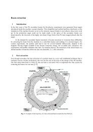
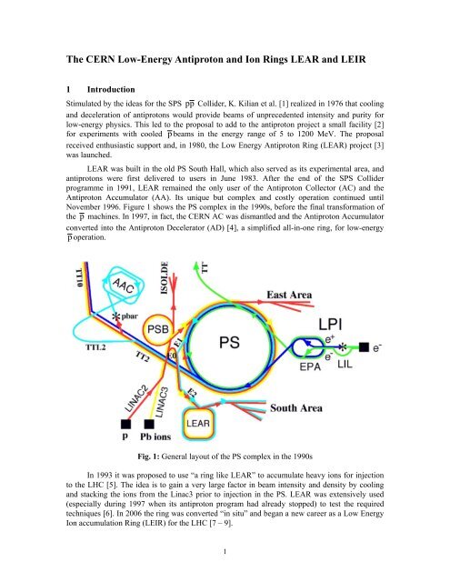
November 1996. Figure 1 shows the PS complex in the 1990s, before the final transformation of<br />
the p machines. In 1997, in fact, the <strong>CERN</strong> AC was dismantled <strong>and</strong> the <strong>Antiproton</strong> Accumulator<br />
converted into the <strong>Antiproton</strong> Decelerator (AD) [4], a simplified all-in-one ring, for low-energy<br />
p operation.<br />
Fig. 1: General layout of the PS complex in the 1990s<br />
In 1993 it was proposed to use “a ring like <strong>LEAR</strong>” to accumulate heavy ions for injection<br />
to the LHC [5]. <strong>The</strong> idea is to gain a very large factor in beam intensity <strong>and</strong> density by cooling<br />
<strong>and</strong> stacking the ions from the Linac3 prior to injection in the PS. <strong>LEAR</strong> was extensively used<br />
(especially during 1997 when its antiproton program had already stopped) to test the required<br />
techniques [6]. In 2006 the ring was converted “in situ” <strong>and</strong> began a new career as a <strong>Low</strong> <strong>Energy</strong><br />
<strong>Ion</strong> accumulation Ring (<strong>LEIR</strong>) for the LHC [7 – 9].<br />
1
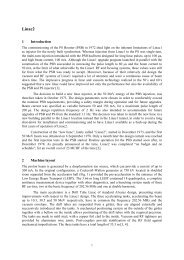
In the following we give a brief description of the accelerator aspects of the low energy<br />
antiproton <strong>and</strong> ion ring. Readers interested in more detail are referred, refs. [2, 3, 10, 11], for<br />
<strong>LEAR</strong>, <strong>and</strong> refs. [7 – 9, 23–27], for <strong>LEIR</strong>.<br />
2 <strong>LEAR</strong><br />
2.1 <strong>The</strong> Magnet Lattice<br />
<strong>LEAR</strong> (Figs. 2 <strong>and</strong> 3) is almost square in shape with a circumference of 78 m (1/8 of the PS). Its<br />
four-period lattice with compact 90° bending magnets <strong>and</strong> eight quadrupole doublets provides<br />
four long straight sections, each of 8 m free length. <strong>The</strong>se served for the installation of large<br />
equipments, in particular the electron-cooler <strong>and</strong> the internal gas jet target experiments. Eight<br />
short straight sections, 1 m long each, accommodate less bulky equipments. <strong>The</strong> C-type magnets<br />
are open to the outside of the ring. This choice simplified injection, ejection, <strong>and</strong> the design of<br />
“exit lines” for neutral states formed in flight in the straight sections ( H<br />
0<br />
, antineutrons, p p-<br />
bound states). <strong>The</strong> exit lines greatly eased the detection of antihydrogen atoms formed by p<br />
interaction with an internal gas target. It was therefore not completely unexpected, when<br />
antihydrogen atoms were experimentally observed at <strong>LEAR</strong> (for the first time in human history!)<br />
in 1996 [12], an event that was widely covered by the media.<br />
Fig. 2: Layout of <strong>LEAR</strong> in the PS South Hall, with injection lines (test-proton <strong>and</strong> H- from the<br />
Linac, antiprotons from the PS), <strong>and</strong> the lines transporting ejected antiprotons towards the<br />
experiments (status 1984)<br />
2
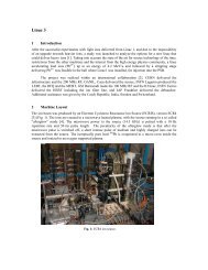
Fig. 3: <strong>LEAR</strong> in the PS South Hall (1990). Clockwise from the bending magnet in the<br />
foreground, the four long straight sections (SS) house: electron cooling (SS3); RF cavities<br />
(SS4); injection <strong>and</strong> ejection (SS1); the internal gas jet target experiment JETSET (SS2). <strong>The</strong><br />
detector of JETSET is partially dismantled. A web of coaxial transmission lines for stochastic<br />
cooling spans across the ring<br />
A particularity of the <strong>LEAR</strong> optics was the very strong focusing: a phase advance of<br />
~250 0 /period yielded an “imaginary transition energy” (decrease of orbit length C with<br />
<br />
momentum, i.e. negative momentum compaction ((<br />
dC / C)<br />
( dp / p)<br />
<br />
2 p<br />
<br />
tr<br />
0 ). This avoids<br />
transition <strong>and</strong> also leads to a large dispersion of the revolution frequencies ( df / f ) ( dp/<br />
p)<br />
,<br />
beneficial for cooling to small momentum spreads <strong>and</strong> for control of instabilities. Other important<br />
features of <strong>LEAR</strong> were the ultra-high vacuum, 10 -12 Torr, for sufficient beam lifetime at low<br />
energy <strong>and</strong>, described below, beam cooling <strong>and</strong> ultra-slow extraction.<br />
2.2 <strong>The</strong> Operating Scheme<br />
A single bunch, of usually a few 10 9 antiprotons, was skimmed off the AA stack at intervals<br />
ranging from 15 minutes to several hours. <strong>The</strong> average consumption, 10 6 p /s, was only 10% of<br />
the maximum accumulation rate of the AA. <strong>The</strong> bunch was decelerated in the PS to 609 MeV/c<br />
<strong>and</strong> transferred to <strong>LEAR</strong>, where it could either be decelerated to as low as 100 MeV/c<br />
(5.3 MeV kinetic energy), or accelerated, up to nominally 2000 MeV/c (1270 MeV).<br />
In the “beam stretcher mode“, used for most of the experiments, ultra-slow extraction<br />
provided a continuous spill until the next fill. In the “internal target” mode for the JETSET<br />
experiment, a beam with an initial intensity of as much as 5×10 10 p was kept circulating for<br />
3
many hours, even days, until most particles had been consumed by interaction with the gas jet<br />
target. For trap experiments, one or several bunches were extracted by a fast kicker.<br />
2.3 Cooling<br />
Stochastic cooling of all three emittances was optimized for several strategic momenta: 609<br />
(injection), 300, 200 <strong>and</strong> 100 MeV/c on the low-energy cycle, <strong>and</strong> 1000, 1500 <strong>and</strong> 1940 MeV/c<br />
on a high-energy cycle. Cooling compensated the adiabatic emittance growth during deceleration<br />
<strong>and</strong> counteracted various heating mechanisms, such as multiple Coulomb scattering, notably on<br />
the internal targets of the JETSET experiment. Final cooling was applied at the momentum at<br />
which the beam was delivered to the users, to provide a highly monochromatic <strong>and</strong> small-sized<br />
beam.<br />
A complex cooling system with a great number of different pickups <strong>and</strong> kickers <strong>and</strong><br />
containing a plethora of switchable delays was necessary to permit cooling at all momenta. For<br />
sufficient signal level, the pickup arrays had to be long. As much as possible they were installed<br />
inside the vacuum chamber in the bending magnets where space was “cheap”. An ever-growing<br />
web of coaxial lines was spun across the ring for the transmission of the signals from pickups to<br />
kickers. Diagonal paths were necessary for cooling at high energy to catch up with the particle<br />
velocity β = v/c 1. For low energy, shorter paths were possible <strong>and</strong> favourable to avoid desynchronization<br />
between off-momentum particles <strong>and</strong> their correction signal (“unwanted<br />
mixing”).<br />
From 1987, electron cooling complemented stochastic cooling. <strong>The</strong> electron cooler, which<br />
had served until 1979 in the Initial Cooling Experiment (ICE) was resuscitated <strong>and</strong> upgraded for<br />
service in <strong>LEAR</strong> at momenta between 300 <strong>and</strong> 100 MeV/c. This device has even survived <strong>LEAR</strong><br />
<strong>and</strong> now operates in the AD.<br />
<strong>The</strong> combination of both cooling methods pioneered in <strong>LEAR</strong> lead to very high quality<br />
beams at low energy with emittances as low as space-charge <strong>and</strong> instabilities permitted, typically<br />
10 9 p with ε ~ 1 π mm mrad <strong>and</strong> Δp/p ~10 -4 . Elaborate stabilization systems were needed to hold<br />
beam instabilities in check.<br />
2.4 Ultra-slow extraction<br />
In the stretcher mode, a spill as constant as possible of some 10 6 p /s was required by the users.<br />
<strong>The</strong> filling sequence was determined by the smallest intensity that the PS was able to h<strong>and</strong>le. <strong>The</strong><br />
limit was pushed down to 10 9 p , some 4 orders of magnitude below its usual value for protons.<br />
Even so, the spill length had to be at least 15 minutes, a formidable challenge, as so far extraction<br />
times of only a few seconds had been achieved. It meant beam stretching (“extraction<br />
time/revolution time”) of 9 orders of magnitude with, on average, less than one particle extracted<br />
per turn. A novel ultra-slow extraction technique was devised for this purposed. It is based on –<br />
yet another – idea by S. van der Meer [13], which was brought to maturity by<br />
W. Hardt [14].<br />
Conventional slow extraction uses a programmed tune change, driving the beam towards a<br />
resonance, which eats into the tune distribution of the beam. <strong>The</strong> time structure of the spill is very<br />
sensitive to all sorts of tune ripple <strong>and</strong> exhibits spikes <strong>and</strong> holes (detrimental to the experiments)<br />
when the sweep is slow.<br />
Ultra-slow (“stochastic”) extraction uses RF noise to diffuse the particles within an<br />
appropriate range of p/p, thereby producing a very-low-density tail on the momentum<br />
4
distribution. <strong>The</strong> chromaticity, dQ/(dp/p), adjusted with sextupole lenses, leads to a<br />
corresponding tail in the Q-distribution <strong>and</strong> the extraction resonance is placed at a Q-value inside<br />
that tail. This largely reduces the influence of Q-ripple, as the density near the resonance is low<br />
<strong>and</strong> particles perform a r<strong>and</strong>om walk around it. <strong>The</strong> spill rate is controlled by the level of the<br />
noise transporting particles from the stack into the tail.<br />
This concept worked admirably well <strong>and</strong> permitted good 15-minute spills in the first runs<br />
in 1983. Very soon, one-hour spills became common. At the end of the <strong>LEAR</strong> era, the number of<br />
transfers per day was minimized by taking from the AA batches of the highest intensity<br />
compatible with safe operation for the experiments. Figure 4 illustrates a 10-hour spill; the record<br />
spill length was 14 hours.<br />
2.5 Performance<br />
During the 14 years of operation, the number of antiprotons consumed by <strong>LEAR</strong> increased from a<br />
Fig. 5: <strong>LEAR</strong> operation statistics from 1993 to 1996. Number of antiprotons injected (bars)<br />
<strong>and</strong> number of spill delivered (small squares)<br />
Fig. 4: A typical spill in the ultra-low extraction, lasting 10 hours. <strong>The</strong> beam is shared by two<br />
experiments (a "splitter magnet" divides the extracted beam). Each point on the curve<br />
represents the rate recorded by the experiments, averaged over 10 s. <strong>The</strong> brief interruption in<br />
the counting rate of OBELIX was for recalibration<br />
5
few 10 11 to 2.6×10 13 per year (Fig. 5). <strong>The</strong> step in 1987/88 is due to the advent of the AC.<br />
Another step occurred in 1991/92 when <strong>LEAR</strong> became the only client of the AC/AA. <strong>The</strong> total<br />
number of antiprotons supplied was around 1.5×10 14 (0.24 nano-gramme).<br />
<strong>The</strong> number of scheduled hours increased from 283 in 1983 to an impressive 5450 in the<br />
final year, 1996. <strong>The</strong> number of spills delivered to the users was usually 90%, <strong>and</strong> always more<br />
than 85%, of those scheduled.<br />
3 <strong>LEIR</strong><br />
3.1 <strong>The</strong> feasibility tests<br />
After the proposal [5] many feasibility tests were conducted through the years 1994 to 1996 <strong>and</strong><br />
finally during the whole year 1997 [6]. <strong>The</strong> main results of these tests were very important for the<br />
final design of the machine:<br />
– <strong>The</strong> possibility to combine a longitudinal <strong>and</strong> horizontal multi-turn injection was<br />
successfully tested.<br />
– It was found that the lead 53 + ions were subject to dielectronic recombination with the<br />
electrons of the electron cooler, leading to large losses <strong>and</strong> hence poor ion<br />
accumulation rate. Contrary to this, lead 54 + ions were found suitable for accumulation<br />
as they showed considerably lower losses. <strong>The</strong> same phenomenon was also observed<br />
for gold ion (same remaining number of electron) at TSR [16] <strong>and</strong> precisely analyzed<br />
for lead ions at Cryring [17].<br />
– On the other h<strong>and</strong> the radiative recombination was found, as expected, due to the very<br />
good vacuum (quantity <strong>and</strong> quality) in <strong>LEAR</strong>, the charge exchange recombination was<br />
found very low. Nevertheless the lost lead ions bombarding the vacuum chamber walls<br />
released into the vacuum a lot of molecules, mainly carbon oxide (a few 10 4 atoms/lost<br />
ion) [6, 18, 19]. This phenomenon was indeed detrimental to the accumulation rate <strong>and</strong><br />
limited the maximum number of accumulated ions.<br />
– A lot of cooling <strong>and</strong> stacking measurements [6] were executed to. <strong>The</strong>y established the<br />
feasibility to accumulate ions in <strong>LEAR</strong>, provided an adaptation of the lattice is made to<br />
inject, cool <strong>and</strong> stack efficiently.<br />
3.2 <strong>The</strong> machine<br />
Operation of <strong>LEIR</strong> sets several requirements on the optics:<br />
– Injection: a relatively large normalized dispersion D/β 1/2 is needed for the elaborate<br />
multi-turn injection [20] with stacking in momentum <strong>and</strong> both horizontal <strong>and</strong> vertical<br />
phase spaces. <strong>The</strong> value obtained (D/β 1/2 ≈ 5) is a bit smaller than the one desired.<br />
– Electron cooling: betatron functions of about 5 m were found optimal for fast electron<br />
cooling [6]. Although a finite dispersion of a few meters was found beneficial for a fast<br />
cooling, it has been decided to have zero dispersion for easy overlap of ions (with large<br />
momentum spread at injection) with electrons. In addition, the extraction installed in<br />
the opposite straight section will profit from the zero dispersion.<br />
– Working point: operation far from (Q H − Q V = −1) resonance <strong>and</strong> clear from other<br />
dangerous resonances was required to obtain good multiturn injection efficiency <strong>and</strong><br />
avoid emittance blow-up.<br />
6
– Aperture: sufficient momentum <strong>and</strong> transverse acceptances had to be provided.<br />
– <strong>Ion</strong> beam lifetime: it should be as high as 15 s to be able to accumulate more than 10 9<br />
lead ions in about a second.<br />
– Multi beam operation: two kinds of beams have to be delivered. <strong>The</strong> EARLY beam is<br />
needed for the starting phase of collision in LHC. It is composed of one bunch per<br />
<strong>LEIR</strong> cycle containing 2.2 10 8 ions. <strong>The</strong> NOMINAL beam is composed of two bunches<br />
containing 4.5 10 8 ions each <strong>and</strong> is needed when LHC will be in full operation.<br />
3.2 General Layout <strong>and</strong> “Bare” Machine<br />
<strong>LEIR</strong> inherits its “square” shape (see Fig. 6) from the former <strong>LEAR</strong>. Quadrupole doublets are<br />
installed in the injection Straight Section 10 (SS10) <strong>and</strong> opposite in SS30. Triplets are used in<br />
SS20 on both sides of the electron cooler <strong>and</strong> in the opposite SS40 suited for extraction. <strong>The</strong> basic<br />
focusing is defined by five quadrupole families, which surprisingly are sufficient to yield a lattice<br />
satisfying all the requirements given above.<br />
Fig. 6: Layout of <strong>LEIR</strong> ring<br />
7
3.3 Compensation of the Electron Cooler<br />
<strong>The</strong> cooler introduces a strong source of coupling due to the longitudinal magnetic field of the<br />
main solenoid. <strong>The</strong> electron cooler magnet system has no azimuthal symmetry in the toroids. <strong>The</strong><br />
coupling introduced is compensated mainly by two solenoids placed symmetrically on either side<br />
of the cooler. In order to compensate the small skew quadrupole components in the toroids <strong>and</strong><br />
the residual coupling of the machine, skew quadrupoles are used. <strong>The</strong>y are located symmetrically<br />
within the triplets. In order to compensate for the changes of the working point <strong>and</strong> the betatron<br />
functions caused by the cooler <strong>and</strong> other coupling elements, corrections to the five quadrupole<br />
families <strong>and</strong> to the setting of the triplet quadrupoles in SS20 via trim power supplies are<br />
programmed. <strong>The</strong> corrections depend quadratically on the ratio between the solenoidal field <strong>and</strong><br />
the beam rigidity, <strong>and</strong> are reduced during acceleration.<br />
3.4 Eddy Current Compensation<br />
<strong>The</strong> <strong>LEIR</strong> bending magnets are C-shaped <strong>and</strong> the vacuum chamber is connected to ground at<br />
various locations. As a consequence, a net eddy current flows along the chamber during the ramp<br />
resulting in a gradient experienced by the beam. It produces strong tune shifts, especially in the<br />
horizontal plane, where the working point moves below the half-integer resonance. This<br />
perturbation (together with the distortion of betatron functions around the ring) has to be<br />
compensated by adding appropriate corrections to the five main quadrupole families.<br />
3.4.1 Beam lifetime<br />
<strong>The</strong> electron beam [21] of the cooler can have a non-uniform density distribution (this<br />
programmed by a control electrode): less density in the center, where the stack sits, to limit the<br />
recombination of ions with cooling electrons, <strong>and</strong> thereby the ion losses; a higher density<br />
elsewhere to allow a fast cooling for the particles having large amplitudes of oscillation.<br />
Nevertheless to limit the outgassing of the vacuum chamber walls, the major part of the<br />
remaining losses are concentrated onto a collimator system [22]. Two parameters were essential:<br />
the impact angle has to be close to 90 degrees; the collimators are made of stainless steel coated<br />
with 30 μm of gold. In addition, the vacuum system has been carefully improved by coating the<br />
vacuum chamber wherever possible with low temperature NEG’s. As for <strong>LEAR</strong> the <strong>LEIR</strong><br />
machine is baked to 300 degrees.<br />
3.4.2 Particularities<br />
Amongst the particularities, let’s notice the following:<br />
– Part of the injection line (from Linac3 to <strong>LEIR</strong> at 4.2 MeV/n) <strong>and</strong> the extraction line<br />
(from <strong>LEIR</strong> to the PS at 72 MeV/n) is common. To avoid bipolar power supplies for the<br />
quadrupoles, a special arrangement of the lattice was made, leading to quadrupoles which<br />
are defocusing for extraction when focusing for injection <strong>and</strong> vice versa.<br />
– <strong>The</strong> multi-turn injection is made through an inclined septum (30 degrees) with horizontal<br />
<strong>and</strong> vertical mis-steering, to avoid as much as possible ions hitting the septum. <strong>The</strong><br />
horizontal oscillation is maintained constant by increasing the incoming beam momentum<br />
<strong>and</strong> decreasing accordingly the local injection bump. This provides a 70 turns injection<br />
(200 s long) with a 60–70% efficiency.<br />
8
– New at <strong>CERN</strong>, but used since long in other laboratories [15], the multi-injection with<br />
stacking-cooling sequence has been imported.<br />
– <strong>The</strong> lattice super-symmetry is only two <strong>and</strong>, in addition, it is heavily distorted by the<br />
electron cooling insertion. As a consequence there is a large number of parameters to be<br />
controlled by the 5 quadrupole families <strong>and</strong> the many trim power supplies. Contrary to<br />
the <strong>LEAR</strong> machine, the <strong>LEIR</strong> transition energy is “real” (~2.5 GeV).<br />
– Due to the low energy of the particles, the swing in frequency is large <strong>and</strong>, in addition,<br />
multi-harmonic operation can be used (RF range 0.5–5 MHz). This lead to the use of low<br />
quality factor RF-cavities, made in collaboration with KEK, <strong>and</strong> loaded with Finemet®<br />
magnetic alloy cores. <strong>The</strong> low level beam control of the RF system is, for the first time at<br />
<strong>CERN</strong>, completely digital.<br />
– <strong>The</strong> commissioning of <strong>LEIR</strong> had to be done just before the commissioning of the LHC.<br />
<strong>The</strong>n, it was a good opportunity to investigate in <strong>LEIR</strong> many of the processes which will<br />
be used at LHC. Amongst them, the FESA technology, the LSA machine parameters<br />
editor <strong>and</strong> trim, the WIC magnet protection system, the LASER fault diagnostic system<br />
were extensively tested.<br />
3.5 <strong>The</strong> <strong>LEIR</strong> performance<br />
3.5.1 From the commissioning to the first operation run<br />
After a long period of setting up the different systems, the machine was first tested with O 4+ in<br />
2005. <strong>The</strong> lattice functions were analyzed by orbit response to small kicks <strong>and</strong> proved to be close<br />
to the design values [23, 24].<br />
Fig. 7: <strong>LEIR</strong> performance for the “EARLY” beam used routinely for setting-up of the PS <strong>and</strong><br />
SPS. <strong>The</strong> figure shows the evolution of the beam current (left) <strong>and</strong> a tomographic reconstruction<br />
of the longitudinal phase space (right)<br />
9
Ring commissioning resumed in the middle of February 2006 with Pb 54+ ions. At the very<br />
beginning, progress was slowed down by difficulties to tune the injection efficiency with lead<br />
ions, again due to problems with injection matching. After improving the injection line setting<br />
[23] <strong>and</strong> setting-up of the transverse damper, clear signs of cooling could be observed on 3rd<br />
March without particular difficulties. <strong>LEIR</strong> commissioning has been completed, almost as<br />
scheduled, in May 2006 with the proof that the EARLY LHC ion beam could be produced (Fig.<br />
7) <strong>and</strong> transported to a region just upstream from the PS injection.<br />
<strong>The</strong> first regular <strong>LEIR</strong> run has taken place in autumn 2006 in order to provide the beam for<br />
setting up the PS with the “early LHC ion beam”. <strong>The</strong> second <strong>LEIR</strong> run started at the beginning<br />
of August 2007. Again, the start-up was carried out without particular difficulties <strong>and</strong> <strong>LEIR</strong> soon<br />
delivered routinely the beam needed for SPS setting-up.<br />
Fig. 8: <strong>LEIR</strong> performance with a high intensity beam. <strong>The</strong> figure shows the evolution of the beam<br />
current (left), a tomographic reconstruction of the longitudinal phase space (right)<br />
Tab. 1: Comparison of <strong>LEIR</strong> design <strong>and</strong> obtained performance for the nominal beam <strong>and</strong> the<br />
beam needed for the early LHC ion runs<br />
NOMINAL<br />
EARLY<br />
Parameter design obtained design obtained<br />
Linac3 current [A] 25 25 25 25<br />
Cycle time [s] 3.6 3.6/4.8 2.4 2.4<br />
Inj. efficiency [%] 50 ~50 50 ~50<br />
Accumulated intensity [10 8 Pb 54+ ] ~10/~15 ~2.5<br />
Intensity for PS [10 8 Pb 54+ ] 9 ~7/~9 2.25 >2.25<br />
Hor. normalized emittance [m] 0.7 0.6/0.9 0.7 0.5<br />
Ver. normalized emittance [m] 0.7 0.3/0.5 0.7 0.24<br />
Long. emittance 4 E t per bunch [eVs/n] 0.05 0.04 0.025 0.02<br />
10
3.5.2 Actual <strong>LEIR</strong> Performance<br />
Table 1 compares <strong>LEIR</strong> performance as observed during the last 2009 run with design values for<br />
the EARLY beam needed for the first LHC ion runs <strong>and</strong> the NOMINAL beam. One observes that<br />
the design performance has been reached for the EARLY beam with transverse emittances<br />
significantly below specifications. Figure 7 (left) shows some details.<br />
After injection, a bit more than the design intensity is circulating. With some losses mainly<br />
during the cooling plateau, the design intensity is ejected. <strong>The</strong> tomographic reconstruction of<br />
longitudinal phase space shows that the design longitudinal emittance is reached. <strong>The</strong> number<br />
quoted in Fig. 7 (right) is the rms for all 208 nucleons. Figures 8 <strong>and</strong> 9 show some measurements<br />
for high intensity beams. With high Linac3 currents, intensities, exceeding the design value at<br />
ejection, have been obtained. However the evolution of the beam current shows a loss at the<br />
beginning of the ramp. This loss is more pronounced for higher beam currents <strong>and</strong>, thus, the<br />
design current has not yet been obtained at ejection. However, investigations on these losses <strong>and</strong><br />
of the NOMINAL <strong>LEIR</strong> beam are carried out only with low priority <strong>and</strong> in parallel to operation.<br />
<strong>The</strong> emittances in all three phase spaces are well within specifications. <strong>The</strong> EARLY beam has<br />
been accelerated up to the entrance of LHC while the NOMINAL beam has been commissioned<br />
in the PS <strong>and</strong> tested in the SPS.<br />
Fig. 9: Spectrogram of the momentum cooling during stacking on the injection front porch. <strong>The</strong><br />
vertical <strong>and</strong> horizontal axis denote time (1.6 s total from top to bottom); <strong>and</strong> momentum spread<br />
(1% full scale). Injection is every 300 ms<br />
11
Fig. 10: Beam intensity (yellow trace) versus time (2 s/div) after accumulation on a very long<br />
plateau. <strong>The</strong> peak intensity is about 16 10 8 Pb 54+ ions; <strong>and</strong> the beam life-time about 14 s<br />
Figure 10 shows that sufficient beam lifetimes (~14 s) for accumulating the nominal<br />
intensity has been obtained. During the 2006 run, intensities by more than a factor two larger than<br />
the design nominal intensity have been accumulated on very long plateaus. Obviously these<br />
would never be possible without good performance of all systems, particularly the<br />
instrumentation [26, 27].<br />
4 CONCLUSIONS<br />
<strong>The</strong> low-energy antiproton programme had been conceived as an “adjunct” to the SPS Collider, at<br />
little extra cost <strong>and</strong> consuming only a small fraction of the antiprotons production. But the results<br />
obtained with <strong>LEAR</strong> soon made it an important <strong>and</strong> very visible part of <strong>CERN</strong>'s activities. <strong>The</strong><br />
interest was such that <strong>LEAR</strong> continued for 5 years beyond the end of the Collider. <strong>The</strong> AD then<br />
took over, <strong>and</strong> holds promise to deliver important physics contributions for several more years to<br />
come.<br />
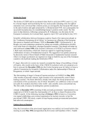
From the outset, the low-energy antiproton programme presented a major challenge to the<br />
accelerator community. <strong>LEAR</strong> was an unconventional enterprise, conceptually <strong>and</strong> technically.<br />
<strong>The</strong> success of the AA <strong>and</strong> <strong>LEAR</strong> has made popular the novel cooling, extraction <strong>and</strong> internal<br />
target approaches. It set the example for a dozen ion cooling rings (“king <strong>LEAR</strong>’s daughters”)<br />
built in Europe <strong>and</strong> the USA [15].<br />
After the end of its programme, <strong>LEAR</strong> was rejuvenated as <strong>LEIR</strong>, an ion accumulator <strong>and</strong><br />
beam shaper to prepare the bunches for LHC. It is now ready to provide the first lead ion beam to<br />
LHC at the end of the year 2010. It will be used also to provide ions for fixed target physics at<br />
SPS, <strong>and</strong> possibly for radiobiological experiment at the exit of <strong>LEIR</strong>. It is the promise of a long<br />
life with ions of different kind for interesting new discoveries.<br />
LONG LIVE <strong>LEIR</strong>!<br />
REFERENCES<br />
[1] K. Kilian, U. Gastaldi, D. Möhl, Deceleration of anti-protons for physics experiments at lowenergy:<br />
a low-<strong>Energy</strong> anti-proton factory, in Proceedings of the Tenth International<br />
Conference on High-<strong>Energy</strong> Accelerators, Serpukov, Soviet Union, 1977, edited by Yu.M.<br />
Ado, A. G. Afonin, V. I. Gridasov, A. F. Dunaitsev, E. A. Mjae, <strong>and</strong> A. A. Naumov (Protvino<br />
12
Inst. High <strong>Energy</strong> Phys, Serpukhov, 1977), p. 179.<br />
[2] P. Lefevre, D. Möhl, G. Plass, <strong>The</strong> <strong>CERN</strong> low energy antiproton ring (<strong>LEAR</strong>) project, in<br />
Proceedings of the Eleventh International Conference on High-<strong>Energy</strong> Accelerators, Geneva,<br />
Switzerl<strong>and</strong>, 1980, edited by W. S. Newman (Birkhäuser, Basel, 1980), p. 819.<br />
[3] G. Plass (Ed.), Design study of a facility for experiments with low energy antiprotons (<strong>LEAR</strong>),<br />
<strong>CERN</strong>-PS-DL-80-7 (1980).<br />
[4] S. Maury (Ed.), Design Study of the <strong>Antiproton</strong> Decelerator: AD, <strong>CERN</strong>-PS-96-043-AR<br />
(1996).<br />
[5] P. Lefevre <strong>and</strong> D. Möhl, Lead ion accumulation scheme for the LHC, in Proceedings of the<br />
Workshop on Beam Cooling <strong>and</strong> Related Topics, Montreux, Switzerl<strong>and</strong>, 1993, edited by J.<br />
Bosser (<strong>CERN</strong>, Geneva, 1994), <strong>CERN</strong> 94-03, p. 411–415.<br />
[6] J. Bosser et al., Experimental investigation of electron cooling <strong>and</strong> stacking of lead ions in a<br />
low energy accumulation ring, Part. Accel. 63 (1999) 171<br />
[7] K. Schindl, <strong>Ion</strong> injector issues, in Proceedings of the Twelfth Chamonix Workshop on LHC<br />
Performance, Chamonix, France, 2004, edited by J. Poole (<strong>CERN</strong>, Geneva 2003), p. 64.<br />
[8] M. Benedikt et al. (Eds), LHC design report, <strong>CERN</strong>-2004-003-V-3 (2004), p. 263–356.<br />
[9] C. Carli et al., <strong>LEIR</strong>: towards the nominal lead ion beam, in Proceedings of the Fourth Asian<br />
Particle Accelerator Conference, Indore, India, 2007, (JACoW, Geneva, 2007) TUPMA085.<br />
[10] M. Chanel, <strong>LEAR</strong> performance, <strong>CERN</strong>-PS-99-040-DI (1999).<br />
[11] D. Möhl, <strong>LEAR</strong>, history <strong>and</strong> early achievements, <strong>CERN</strong>-PS-99-034-DI (1999).<br />
[12] G. Baur et al., Production of antihydrogen, Phys. Lett. B 368 (1996) 251.<br />
[13] S. van der Meer, Stochastic Extraction, a <strong>Low</strong> Ripple Version of Resonant Extraction, <strong>CERN</strong>-<br />
PS-AA-78-6 (1978).<br />
[14] R. Cappi, W. Hardt <strong>and</strong> C. Steinbach, Ultra slow extraction with good duty factor, in<br />
Proceedings of the Eleventh International Conference on High-<strong>Energy</strong> Accelerators, Geneva,<br />
Switzerl<strong>and</strong>, 1980, edited by W. S. Newman (Birkhäuser, Basel, 1980), p. 335.<br />
[15] B. Franzke, Review of heavy ion storage rings, in Proceedings of the Third European Particle<br />
Accelerator Conference, Berlin, Germany, 1992, edited by H. Henke, H. Homeyer, <strong>and</strong> C.<br />
Petit-Jean-Genaz (Ed. Frontières, Gif-sur-Yvette, 1992), p. 367.<br />
[16] A. Wolf et al., Recombination in electron coolers Nucl. Instr. <strong>and</strong> Meth. A 441 (2000) 183–<br />
190.<br />
[17] H. Danared et al., QED effects in Cu-like Pb recombination, resonances near threshold, Phys.<br />
Rev. Lett. 86 (2001) 5027–5030.<br />
[18] N. Madsen, Vacuum Changes during Accumulation of Pb 54+ in <strong>LEIR</strong>, PS/DI Note 99-21<br />
(1999).<br />
[19] E. Mahner et al., Molecular Desorption of Stainless Steel Vacuum Chambers Irradiated<br />
with 4.2 MeV/u Lead <strong>Ion</strong>s, <strong>CERN</strong>-LHC-Project-Report-624, Phys. Rev. ST Accel. Beams<br />
6 (2003) 013201.<br />
[20] C. Carli, S. Maury <strong>and</strong> D. Möhl, Combined longitudinal <strong>and</strong> transverse multiturn injection<br />
in a heavy ion accumulator, in Proceedings of the Seventeenth Particle Accelerator<br />
Conference, Vancouver, Canada, 1997, edited by M. Comyn, M. K. Craddock, M. Reiser,<br />
<strong>and</strong> J. Thomson (IEEE, Piscataway, NJ, 1998), p. 976.<br />
13
[21] G. Tranquille et al., Commissioning of the <strong>LEIR</strong> electron cooler with Pb 54+ ions, in<br />
Proceedings of Twentieth Russian Conference on Charged Particle Accelerators,<br />
Novosibirsk, Russia, 2006 (JACoW, Geneva, 2006), WEBO01.<br />
[22] J. Pasternak et al., A collimation scheme for ions changing charge state in the <strong>LEIR</strong> ring, in<br />
Proceedings of Twenty First Particle Accelerator Conference, Knoxville, Tennessee, 2006,<br />
edited by M. Arena, J. Chrin, M. Comyn, C. Eyberger, C. Horak, L. Liljeby, M. Marx, H.<br />
Owen, J. Patton, <strong>and</strong> C. Petit-Jean-Genaz, (JACoW, Geneva, 2006), p. 3816.<br />
[23] C. Carli et al., <strong>LEIR</strong> commissioning, in Proceedings of Tenth European Particle<br />
Accelerator Conference, Edinburgh, Scotl<strong>and</strong>, 2006, edited by C. Biscari, H. Owen, C.<br />
Petit-Jean-Genaz, <strong>and</strong> J. Poole (JACoW, Geneva, 2006), p. 1876.<br />
[24] C. Carli et al., <strong>LEIR</strong> Lattice, in Proceedings of Tenth European Particle Accelerator<br />
Conference, Edinburgh, Scotl<strong>and</strong>, 2006, edited by C. Biscari, H. Owen, C. Petit-Jean-<br />
Genaz, <strong>and</strong> J. Poole (JACoW, Geneva, 2006), p. 261.<br />
[25] G. Tranquille, Electron cooling experiments at <strong>LEIR</strong>, in Proceedings of the Eleventh<br />
European Particle Accelerator Conference, Genoa, Italy, 2008, edited by C. Biscari <strong>and</strong> C.<br />
Petit-Jean-Genaz (JACoW, Geneva, 2008), THPP057.<br />
[26] G. Tranquille et al., Cooled beam diagnostics on <strong>LEIR</strong>, in Proceedings of the Eleventh<br />
European Particle Accelerator Conference, Genoa, Italy, 2008, edited by C. Biscari <strong>and</strong> C.<br />
Petit-Jean-Genaz (JACoW, Geneva, 2008), TUPC102.<br />
[27] C. Bal et al., <strong>LEIR</strong> beam instrumentation, in Proceedings of the Seventh European<br />
Workshop on Beam Diagnostics <strong>and</strong> Instrumentation for Particle Accelerators, Lyon,<br />
France, 2005 (JACoW, Geneva, 2005), p. 57.<br />
14