Beam extraction - 50th anniversary of the CERN Proton Synchrotron
Beam extraction - 50th anniversary of the CERN Proton Synchrotron
Beam extraction - 50th anniversary of the CERN Proton Synchrotron

Create successful ePaper yourself
Turn your PDF publications into a flip-book with our unique Google optimized e-Paper software.
<strong>Beam</strong> <strong>extraction</strong><br />
1 Introduction<br />
In <strong>the</strong> first years <strong>of</strong> <strong>the</strong> PS, secondary beams for <strong>the</strong> physics experiments were generated from targets<br />
introduced inside <strong>the</strong> machine vacuum chamber. This straightforward method had three drawbacks: a) <strong>the</strong><br />
irradiation <strong>of</strong> <strong>the</strong> machine became severe as <strong>the</strong> intensity request thanks to new physics discoveries went<br />
up; b) <strong>the</strong> production angle could not be made small; c) <strong>the</strong> optics <strong>of</strong> <strong>the</strong> secondary beams was<br />
deteriorated by <strong>the</strong> traversal <strong>of</strong> <strong>the</strong> highly non-linear fringe field <strong>of</strong> <strong>the</strong> PS main magnet placed after <strong>the</strong><br />
target.<br />
As <strong>the</strong> demand for secondary beams increased, it became necessary to overcome <strong>the</strong>se difficulties<br />
by extracting <strong>the</strong> beam from <strong>the</strong> machine in a controlled manner and sending it to external targets. For<br />
counter experiments, <strong>the</strong> particle spill had to last for several hundred milliseconds, adapted to <strong>the</strong><br />
magnetic flat-top length available at <strong>the</strong> chosen <strong>extraction</strong> energy, <strong>the</strong> so-called slow <strong>extraction</strong>. For<br />
experiments with bubble chambers and, later, for neutrino physics, <strong>the</strong> <strong>extraction</strong> <strong>of</strong> <strong>the</strong> whole beam or a<br />
limited number <strong>of</strong> bunches within one turn was desirable, i.e., a fast <strong>extraction</strong>.<br />
2 Fast <strong>extraction</strong><br />
Even though nowadays <strong>the</strong> fast <strong>extraction</strong> <strong>of</strong> a particle beam is a very well established technique that is<br />
routinely used in circular accelerators, this was not <strong>the</strong> case at <strong>the</strong> time <strong>of</strong> <strong>the</strong> design <strong>of</strong> <strong>the</strong> PS machine.<br />
The first study dates back to 1954 [1], but one had to wait until 1963 to implement <strong>the</strong> first system for<br />
extracting <strong>the</strong> beam over one turn [2–5].<br />
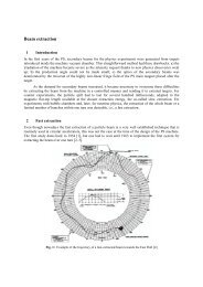
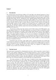
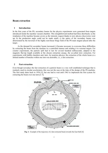
Fig. 1: Example <strong>of</strong> <strong>the</strong> trajectory <strong>of</strong> a fast-extracted beam towards <strong>the</strong> East Hall [4]<br />
1
An example <strong>of</strong> an <strong>extraction</strong> trajectory dating from 1969 is shown in Fig. 1, where <strong>the</strong> beam was<br />
delivered to <strong>the</strong> experimental East Hall. The kicker magnet was placed in SS97 and <strong>the</strong> <strong>extraction</strong> septum<br />
magnet in Straight Section SS58. Extraction <strong>of</strong> protons from SS58 was operational from 1965 to 1982 and<br />
went on afterwards for antiprotons and electrons towards <strong>the</strong> SPS. Fast <strong>extraction</strong> from SS74 was used<br />
from 1967 to 1980 for <strong>the</strong> neutrino, g–2 and ICE experiments. Nowadays, <strong>the</strong> only remaining fast<br />
<strong>extraction</strong> is performed in SS16 towards <strong>the</strong> Super <strong>Proton</strong> <strong>Synchrotron</strong> (SPS), <strong>the</strong> AD machine and <strong>the</strong> n-<br />
TOF experiment. The full-aperture kicker magnets are located in SS71 and SS79, while <strong>the</strong> long<br />
<strong>extraction</strong> septum magnet is located in SS16.<br />
2.1 Fast kickers<br />
The initiating element for fast <strong>extraction</strong> is <strong>the</strong> kicker which imparts a horizontal betatronic<br />
oscillation to <strong>the</strong> bunches to be ejected. They are <strong>the</strong>n deflected out <strong>of</strong> <strong>the</strong> circulating orbit by a<br />
downstream septum magnet. In addition, local bumps are needed at <strong>the</strong> <strong>extraction</strong> septum.<br />
Kicker rise and fall times must be less than 80 ns for clean <strong>extraction</strong> <strong>of</strong> a limited number <strong>of</strong> beam<br />
bunches. This is obtainable from single-turn magnets, usually <strong>of</strong> travelling wave type, operating at high<br />
voltages and currents. Switch jitter must be low and reliability high.<br />
In its 50 years <strong>the</strong> PS has known three kickers, two were successes and one a failure. The first,<br />
installed in <strong>the</strong> early sixties, was <strong>of</strong> limited aperture and was hydraulically positioned after beam<br />
acceleration. It used lumped element pulse forming networks (PFNs), spark gap switches, and electrolytic<br />
terminating loads. The system operated successfully for over 10 years but <strong>the</strong> movement into <strong>the</strong> beam<br />
line after acceleration imposed operational restrictions. A full-aperture (FAK) system was proposed to<br />
succeed it and <strong>the</strong> project started in 1964.<br />
At <strong>the</strong> heart <strong>of</strong> <strong>the</strong> FAK was <strong>the</strong> use <strong>of</strong> ferrite rings left over from <strong>the</strong> PS cavities. These would<br />
serve as magnet yoke, <strong>the</strong> dielectric for <strong>the</strong> magnet capacitance, and also form an important part <strong>of</strong> <strong>the</strong><br />
vacuum envelope around <strong>the</strong> beam. To make <strong>the</strong>m impervious <strong>the</strong>y were pre-impregnated with epoxy<br />
resin before assembly into two glued back-to-back 2 m stacks. Fortunately, prior to final assembly it was<br />
shown that a continuous ferrite stack does not behave like a travelling wave magnet. To make it do so,<br />
alternate ferrites were replaced by Araldite rings. The completed magnet was successfully laboratory<br />
tested prior to installation in SS66 where disaster struck. The residual electric charge on <strong>the</strong> epoxy<br />
surfaces after a single kicker pulse prevented fur<strong>the</strong>r 50 MeV injection for several minutes. With a<br />
provisional semiconducting Mylar tube in <strong>the</strong> aperture <strong>the</strong> FAK worked as designed, but that was not a<br />
long-term solution. The FAK was removed to <strong>the</strong> museum and deemed a failure because <strong>of</strong> trying to get<br />
too much out <strong>of</strong> a stack <strong>of</strong> surplus ferrite rings.<br />
The need for a new kicker for <strong>the</strong> PS remained. To meet future operations this had to be<br />
full-aperture and be able to eject any number <strong>of</strong> bunches up to six times per machine cycle at intervals<br />
down to 50 ms. A single-module kicker <strong>of</strong> 80 ns rise time would require a PFN voltage close to 1 MV so<br />
<strong>the</strong> new system would require at least 10 modules and 20 or 30 switches depending on whe<strong>the</strong>r <strong>the</strong> pulse<br />
fall used a ‘tail-biter’ (see Fig. 2). Clearly, <strong>the</strong> choice <strong>of</strong> switch would be critical; spark gaps could handle<br />
<strong>the</strong> voltage, current, and jitter initially but <strong>the</strong>ir long-term maintenance in such numbers could pose a<br />
serious problem. An alternative would be <strong>the</strong> hydrogen thyratron developed for military radar but never<br />
operated at dI/dt rates needed for kickers. The first step was evaluation <strong>of</strong> thyratron dI/dt capability. Six<br />
tubes were tested in <strong>the</strong> laboratory, switching 15 ohm cables charged to 80 kV. Provided that <strong>the</strong> cables<br />
were charged in a few ms from pulsed resonant supplies, <strong>the</strong> average switch dI/dt was 100 A/ns, easily<br />
maintained over 100 million pulses in a yearlong test, with jitter smaller than 5 ns. The thyratron option<br />
was <strong>the</strong>refore chosen. Very-low-attenuation 15 ohm SF 6 pressurized poly<strong>the</strong>ne tape PFN cable would be<br />
charged to 80 kV in under 4 ms by a resonant supply. Cable discharge would be by thyratrons at each end,<br />
<strong>the</strong>ir relative timing controlling <strong>the</strong> kicker pulse duration. No tail-biter would be needed because <strong>of</strong> <strong>the</strong><br />
2
high-quality cable used for <strong>the</strong> PFN. The magnet would be a 15 ohm delay-line, installed in machine<br />
vacuum using ferrite only as <strong>the</strong> magnet yoke. Interleaved high-grade-finish aluminium alloy plates<br />
would provide <strong>the</strong> needed capacitance, <strong>the</strong> dielectric being <strong>the</strong> machine vacuum. The total system would<br />
comprise 12 modules, nine in SS71 and three in SS79 [6].<br />
Fig. 2: Left: a module <strong>of</strong> KFA71 or KFA79. Right: Switches for KFA71<br />
The initially authorized project was for SS71 only, possibly due to some lingering doubts after <strong>the</strong><br />
failure <strong>of</strong> KFA66. Construction went without surprises and after laboratory testing nine modules were<br />
installed in 1973 in SS71. They functioned correctly and were joined a little later by <strong>the</strong> three modules <strong>of</strong><br />
SS79. After 36 years <strong>of</strong> service <strong>the</strong> system is still in use. There have been no high-voltage breakdowns<br />
and thyratron switching is trouble-free, average life exceeding 20 000 hours. Overall system availability<br />
has been high. After <strong>the</strong> failure <strong>of</strong> KFA66, <strong>the</strong> new version KFA71+KFA79 has been a success.<br />
2.2 Extraction septa<br />
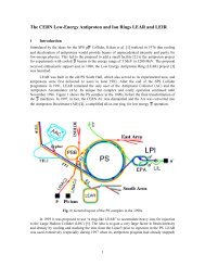
The first septum magnet was installed in SS01 in 1963. A first neutrino experiment had been set up in <strong>the</strong><br />
South Hall with <strong>the</strong> <strong>CERN</strong> heavy liquid bubble chamber, a spark chamber experiment, and in <strong>the</strong> end <strong>the</strong><br />
Ecole Polytechnique heavy liquid chamber. The hope was that <strong>CERN</strong> might beat BNL on <strong>the</strong> ‘2<br />
neutrinos’ question, but <strong>the</strong>y were faster by a few months.<br />
The next operational septum magnet was installed in 1964 in SS58 for <strong>the</strong> East Area bubble<br />
chambers. The South-East Area was <strong>the</strong>n specially built for <strong>the</strong> neutrino beam in 1965 and <strong>extraction</strong><br />
from SS74 was installed with hardware transferred from SS01. Then came <strong>the</strong> long septum 16 for<br />
<strong>extraction</strong> towards <strong>the</strong> ISR and bubble chambers at <strong>the</strong> end <strong>of</strong> <strong>the</strong> West Area. Since <strong>the</strong> vacuum required<br />
in <strong>the</strong> PS at that time was not very high, <strong>the</strong> septum yokes were built <strong>of</strong> packets <strong>of</strong> laminations glued<br />
toge<strong>the</strong>r with Araldite [7].<br />
Later on, since lead ions required better vacuum, new models were developed in <strong>the</strong> early 1990s<br />
without organic materials. Standard 0.35 mm thick steel laminations with a 3% silicon content were used,<br />
insulated on both sides with an inorganic coating [8].<br />
The cooling circuit comprises two thin-walled stainless steel tubes embedded (and brazed) in premachined<br />
slots in <strong>the</strong> septum conductor. This reduces erosion <strong>of</strong> <strong>the</strong> cooling circuit caused by <strong>the</strong> high<br />
water speeds <strong>of</strong> up to 10 m/s.<br />
3
The tanks are cylindrical, bakeable, and equipped with RF beam screens to insure <strong>the</strong> continuity <strong>of</strong><br />
<strong>the</strong> RF impedance. The magnets can be moved remotely in <strong>the</strong> radial and angular directions, while <strong>the</strong>ir<br />
vacuum tanks remain fixed.<br />
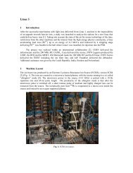
For SMH16 (Septum Magnetic Horizontal in SS16, see Fig. 3), <strong>the</strong> maximum field is 1.2 T for a<br />
pulsed current <strong>of</strong> 28.5 kA. The fringe field measured is less than 1/1000 <strong>of</strong> <strong>the</strong> gap field at a 50 mm<br />
distance from <strong>the</strong> septum conductor.<br />
Fig. 3: Extraction septum magnet 16 (photo taken in 1994)<br />
These thinly laminated magnets need to be baked out to obtain <strong>the</strong> required vacuum. Therefore<br />
infra red lamps are installed under vacuum to heat up <strong>the</strong> magnet, while keeping <strong>the</strong> vacuum vessel and<br />
vacuum seals at acceptable temperatures. After <strong>the</strong> bake-out cycle, consisting <strong>of</strong> a quasi linear<br />
temperature increase to 200 ºC over 18 hours, a 24-hour flat top at 200 ºC, and an exponential<br />
temperature decrease <strong>of</strong> approximately 72 hours, a vacuum <strong>of</strong> 6×10 -10 to 4×10 -9 mbar is achieved in <strong>the</strong><br />
tank.<br />
3 Slow <strong>extraction</strong><br />
A slow <strong>extraction</strong> over thousands <strong>of</strong> turns obtained by pushing <strong>the</strong> beam away from <strong>the</strong> centre <strong>of</strong><br />
<strong>the</strong> vacuum chamber toward a septum magnet would not work. The order <strong>of</strong> magnitude <strong>of</strong> <strong>the</strong> beam size<br />
is 20 mm and an <strong>extraction</strong> over approximately 200 000 machine revolutions was needed: <strong>the</strong> jump <strong>of</strong><br />
particles per turn at a first septum location would <strong>the</strong>n be 1/10 µm, far less than <strong>the</strong> thinnest feasible<br />
septum (at <strong>the</strong> PS a 100 µm electrostatic septum is used). In this context, <strong>the</strong> use <strong>of</strong> transverse resonance<br />
can enormously increase this jump, which is also called spiral pitch.<br />
4
3.1 Integer resonance <strong>extraction</strong><br />
3.1.1 Principle<br />
The first use <strong>of</strong> resonances for <strong>extraction</strong> from a particle accelerator dates from <strong>the</strong> early 1950s at <strong>the</strong><br />
University <strong>of</strong> Chicago ‘Fermi’ synchrocyclotron. It was later proposed for <strong>the</strong> first time for a synchrotron<br />
in 1961 for <strong>the</strong> PS machine [9, 10]. The scheme was based on integer <strong>extraction</strong>.<br />
The radial betatron wavelength <strong>of</strong> <strong>the</strong> machine, which is normally about 6.25, is reduced to 6 by<br />
energizing one or more quadrupoles and some sextupoles. A stable area in <strong>the</strong> transverse phase space<br />
appears, surrounded by unstable phase space (see Fig. 4). Extraction is achieved by pushing <strong>the</strong> beam out<br />
<strong>of</strong> <strong>the</strong> stable area so that particles move away along <strong>the</strong> single separatrix. They are <strong>the</strong>n captured and<br />
extracted by a septum magnet. In <strong>the</strong>ory <strong>the</strong> method has a high efficiency and produces an extracted beam<br />
with a small emittance and narrow energy spectrum, without raising any impossible technical problems.<br />
Fig. 4: Example <strong>of</strong> typical phase-space diagram for integer resonant slow <strong>extraction</strong><br />
3.1.2 Implementation<br />
The first tests at <strong>the</strong> PS were conducted in 1964 [11]. The beam was extracted from SS01 (see Fig. 5,<br />
left), <strong>the</strong> main, long, straight section used for beams into <strong>the</strong> South experimental hall. Conditions for<br />
ejection were achieved by pulsing sextupoles in SS25, 55 and 75 with currents <strong>of</strong> one polarity, sextupoles<br />
in SS15, 35, 65 and 95 with currents <strong>of</strong> opposite polarity, and also a quadrupole in SS99 located 1/8<br />
betatron wave-length upstream from <strong>the</strong> septum magnet at SS01.<br />
The septum magnet, designed with a different ejection system in mind had an aperture <strong>of</strong> 28 mm<br />
wide by 30 mm high, <strong>the</strong> effective septum thickness being 4.5 mm. From <strong>the</strong> standby position at <strong>the</strong><br />
outside <strong>of</strong> <strong>the</strong> CPS vacuum chamber it was plunged to its working position in about 150 ms.<br />
Originally a distance <strong>of</strong> 25 mm between <strong>the</strong> central orbit and <strong>the</strong> nearby edge <strong>of</strong> <strong>the</strong> septum was<br />
specified. This was changed afterwards to 20 mm (Fig. 5, right). The 5 kA power supply, a six phase<br />
mercury vapour rectifier, produced a field ripple <strong>of</strong> several per cent, <strong>the</strong> exact value depending on <strong>the</strong><br />
particular current pulse used. This ripple could be reduced by an order <strong>of</strong> magnitude through insertion <strong>of</strong> a<br />
9 mH choke <strong>of</strong> low resistance (a spare CPS magnet unit, no. 102) in <strong>the</strong> circuit. However, as <strong>the</strong> cooling<br />
capacity <strong>of</strong> <strong>the</strong> septum magnet was limited, <strong>the</strong> longer current rise-time produced by <strong>the</strong> choke led to a<br />
5
shortening <strong>of</strong> <strong>the</strong> usable flat top in <strong>the</strong> septum currents. Therefore half <strong>the</strong> choke inductance was<br />
sometimes used.<br />
Fig. 5: Left: <strong>the</strong> <strong>extraction</strong> area. Right: beam and septum magnet positions.<br />
The efficiency <strong>of</strong> <strong>extraction</strong> during <strong>the</strong> first tests was <strong>of</strong> <strong>the</strong> order <strong>of</strong> 50%, limited by <strong>the</strong> thickness<br />
<strong>of</strong> <strong>the</strong> septum <strong>of</strong> <strong>the</strong> extractor magnet. However, <strong>the</strong> resonant <strong>extraction</strong> was shown to be possible and it<br />
was decided to implement it towards <strong>the</strong> East Hall. The time structure <strong>of</strong> <strong>the</strong> burst was still poor owing to<br />
<strong>the</strong> imperfect regulation <strong>of</strong> power supplies at that time. The oscillogram <strong>of</strong> <strong>the</strong> spill and o<strong>the</strong>r relevant<br />
parameters is shown on Fig. 6.<br />
Fig. 6: Oscillogram <strong>of</strong> beam burst for SS01 integer <strong>extraction</strong><br />
In 1965 an integer resonance <strong>extraction</strong> was installed with an <strong>extraction</strong> septum in SS58, shared<br />
with <strong>the</strong> fast <strong>extraction</strong>. One year after, <strong>the</strong> system was overhauled and <strong>the</strong> <strong>extraction</strong> septum was<br />
installed in SS62. The efficiency had improved but was still lower than 80%, causing heavy losses on <strong>the</strong><br />
septum. The external target 64 soon disappeared and physicists received <strong>the</strong>ir particles from external<br />
targets.<br />
In 1967, <strong>the</strong> efficiency was fur<strong>the</strong>r improved by means <strong>of</strong> <strong>the</strong> installation <strong>of</strong> a thin septum magnetic<br />
lens, 0.2 mm thick, in SS79.<br />
6
A last improvement came in 1971 with <strong>the</strong> use <strong>of</strong> a first-stage separation <strong>of</strong> <strong>the</strong> extracted beam<br />
through an electrostatic septum. Efficiency could now reach values exceeding 90%.<br />
3.2 Third-integer resonance ‘Square’ <strong>extraction</strong><br />
3.2.1 Choice <strong>of</strong> <strong>the</strong> resonance<br />
In <strong>the</strong> late 1960s it was decided to build <strong>the</strong> West Hall. A new <strong>extraction</strong> scheme had to be developed to<br />
provide for East or West area <strong>extraction</strong>s whilst sharing with internal targets. The choice <strong>of</strong> <strong>the</strong> thirdorder<br />
resonance was made for several reasons. Three separatrices allow <strong>the</strong> possibility for three times<br />
more <strong>extraction</strong> straight sections [12]. Moreover, efficiency when sharing with an internal target is better<br />
than with integer resonance <strong>extraction</strong>. The final proposal was made in 1971.<br />
3.2.2 Implementation<br />
Commissioning <strong>of</strong> <strong>the</strong> Square, Semi QUAdrupole Resonant Extraction, from SS16 or SS62 took place in<br />
1972 (see <strong>the</strong> layout in Fig. 7) [13, 14]. Sharing was possible with internal targets 1 or 8, and later on with<br />
1 alone.<br />
Three septa were used for each <strong>extraction</strong>: an electrostatic in SS83 for <strong>the</strong> first step (0.1 mm width),<br />
a thin magnetic septum in SS85 for <strong>the</strong> second stage (1.5 mm width), and thick magnetic septum (6 mm<br />
width) for <strong>the</strong> final <strong>extraction</strong>s in SS16 or SS62 (in this last case <strong>the</strong>re were even two <strong>extraction</strong> magnets<br />
in SS61 and SS62).<br />
Fig. 7: Layout <strong>of</strong> <strong>the</strong> equipments for <strong>the</strong> Square <strong>extraction</strong> in <strong>the</strong> late 1980s<br />
The resonance was driven by a standard quadrupole in SS23 and a non-linear magnet called semiquadrupole,<br />
located in SS53. A cross-section <strong>of</strong> this magnet, which is essentially one half <strong>of</strong> a Pan<strong>of</strong>sky<br />
quadrupole, is shown in Fig. 8. The main coils create <strong>the</strong> non-uniform field and dipole coils compensate<br />
<strong>the</strong> dipole component <strong>of</strong> <strong>the</strong> field at <strong>the</strong> centre.<br />
7
A certain amount <strong>of</strong> ‘Q-gymnastics’ is necessary to prepare <strong>the</strong> ejection. The beam is first brought<br />
to <strong>the</strong> inside half <strong>of</strong> <strong>the</strong> vacuum chamber, <strong>the</strong>n <strong>the</strong> horizontal tune is increased from its normal value <strong>of</strong><br />
about 6.25 to about 6.36 by means <strong>of</strong> an auxiliary quadrupole. Finally <strong>the</strong> semi-quadrupole is switched on<br />
and, after de-bunching, <strong>the</strong> particles are spilt by a negative slope on <strong>the</strong> main field flat-top. The reason for<br />
this is that <strong>the</strong> negative chromaticity requires that <strong>the</strong> resonance be approached from higher Q values so<br />
that <strong>the</strong> beam is pushed into <strong>the</strong> <strong>extraction</strong> toward <strong>the</strong> outside.<br />
Fig. 8: The semi-quadrupole and its magnetic field<br />
The phase space plots in Fig. 9 show <strong>the</strong> way <strong>the</strong> beam flowing out in <strong>the</strong> separatrices is split at <strong>the</strong><br />
electrostatic septum and how it behaves at <strong>the</strong> entrance <strong>of</strong> <strong>the</strong> thin septum magnet.<br />
Fig. 9: Left: phase space plot at ES83. Right: phase space plot at TSM85.<br />
Sharing was used essentially with internal target 1 until all physics experiments disappeared from<br />
<strong>the</strong> South Hall in 1981. All internal targets were thus suppressed to avoid excessive irradiation <strong>of</strong> <strong>the</strong><br />
machine components. Efficiency for <strong>extraction</strong> 62 alone reached 93%, losses being shared on <strong>the</strong><br />
electrostatic and first magnetic septum.<br />
De-bunching was and still is performed before <strong>extraction</strong>. It has several advantages: it eliminates<br />
<strong>the</strong> accelerating frequency structure, precludes any interaction with beam controls loops, and allows <strong>the</strong><br />
enlargement <strong>of</strong> Δp/p which decreases <strong>the</strong> sensitivity to low-frequency ripples. In 1987, <strong>the</strong> maintenance <strong>of</strong><br />
8
<strong>the</strong> semi-quadrupole began to raise problems and it was exchanged for a quadrupole and two sextupoles<br />
which gave about <strong>the</strong> same effect so that <strong>the</strong> <strong>extraction</strong> performance was not altered.<br />
3.3 Third-integer resonance SE61 <strong>extraction</strong><br />
3.3.1 Reasons for a new <strong>extraction</strong> system and its principle<br />
In <strong>the</strong> late 1980s, <strong>the</strong> requirements for slow <strong>extraction</strong> had changed:<br />
– There was no more <strong>extraction</strong> towards <strong>the</strong> West Hall.<br />
– There were no more internal targets.<br />
– The PS was accelerating leptons for LEP on certain cycles and <strong>the</strong> electrostatic and even <strong>the</strong><br />
magnetic septa placed towards <strong>the</strong> outside <strong>of</strong> <strong>the</strong> machine orbit suffered from synchrotron<br />
radiation during <strong>the</strong>re cycles<br />
– It was desirable to have fewer septa to save space in <strong>the</strong> machine and reduce <strong>the</strong> maintenance<br />
effort.<br />
– Better vacuum was necessary to prepare for ions, so that organic material was banished in<br />
vacuum.<br />
– The septum magnets had aged.<br />
– The systematic losses on magnetic septa were excessive.<br />
A new <strong>extraction</strong> scheme was developed to fit <strong>the</strong>se requirements and benefit from <strong>the</strong> less<br />
stringent specifications (no more West Hall and internal targets) [15–17]. Its main characteristics are:<br />
– Protection <strong>of</strong> <strong>the</strong> septa from synchrotron radiation during lepton cycles since <strong>the</strong>y are placed<br />
towards <strong>the</strong> inside <strong>of</strong> <strong>the</strong> machine or are outside vacuum.<br />
– Reduced number <strong>of</strong> septa for less maintenance (only one septum magnet in vacuum instead <strong>of</strong><br />
three before).<br />
– Improved vacuum (required for ion acceleration): <strong>the</strong> thin septum magnet can be baked out, <strong>the</strong><br />
tank is made <strong>of</strong> vacuum fired 316LN stainless steel, and <strong>the</strong>re is no organic material in vacuum.<br />
– Systematic losses due to chromatic effects at <strong>the</strong> thin septum magnet are avoided through<br />
adjustment <strong>of</strong> local dispersion coefficients at <strong>the</strong> electrostatic and thin magnetic septa.<br />
3.3.2 Layout <strong>of</strong> SE61<br />
The new <strong>extraction</strong> was commissioned in March 1992 and regular operation could start immediately [18].<br />
The elements installed in <strong>the</strong> PS machine are (Fig. 10):<br />
9
– Quadrupoles (in SS29 and SS87) to raise Q h<br />
from 6.2 to 6.33, increase β h<br />
at <strong>the</strong> septa, and<br />
decrease <strong>the</strong> horizontal dispersion at <strong>the</strong> electrostatic septum and increase it at <strong>the</strong> first magnetic<br />
septum.<br />
– Sextupoles (one in SS7 and two in SS19) to provide <strong>the</strong> 19th harmonic defining <strong>the</strong> stable and<br />
unstable phase areas, and <strong>the</strong> zero harmonic to decrease <strong>the</strong> horizontal chromaticity |ξ h<br />
|.<br />
– One electrostatic septum in SS23 on <strong>the</strong> machine centre side (Fig. 11, left).<br />
– One magnetic septum in SS57 under vacuum on <strong>the</strong> machine centre side (<strong>the</strong> only magnetic<br />
septum under vacuum) (Fig. 11, right).<br />
– One magnetic septum in SS61 outside vacuum (Fig. 12, left).<br />
– Bumpers in SS19 and 27 to approach <strong>the</strong> electrostatic septum.<br />
– Bumpers in SS53, 59, 61 (septum type, Fig. 12, right) and 67 to approach <strong>the</strong> beam to both<br />
magnetic septa.<br />
D53<br />
EXTRACTOR SEPTUM<br />
MAGNET 61<br />
D59<br />
FIRST<br />
SEPTUM<br />
MAGNET 57<br />
D61<br />
(septum)<br />
D67<br />
D27<br />
QUADRUPOLE 29<br />
<strong>CERN</strong> PS SLOW<br />
EXTRACTION<br />
ELECTROSTATIC<br />
SEPTUM 23<br />
QUADRUPOLE 87<br />
D19<br />
SEXTUPOLE 19<br />
SEXTUPOLE 7<br />
Fig. 10: Layout <strong>of</strong> <strong>the</strong> elements for SE61<br />
10
Fig. 11: Left: electrostatic septum in SS23. Right: <strong>the</strong> thin septum in its tank.<br />
In 2007, <strong>the</strong> sextupoles in SS19 had to be displaced to free <strong>the</strong> straight section in conjunction with<br />
<strong>the</strong> installation <strong>of</strong> <strong>the</strong> multi-turn <strong>extraction</strong> (MTE). They were first placed in SS03 but it turned out that<br />
<strong>the</strong> separatrices were curved and that <strong>the</strong> efficiency was lowered and losses increased (paren<strong>the</strong>tically, <strong>the</strong><br />
initial performance was restored by using octupole magnets to re-shape <strong>the</strong> separatrices at large<br />
amplitude). Never<strong>the</strong>less, to ease operation, it was decided to find a better place for <strong>the</strong> sextupoles, which<br />
were <strong>the</strong>n moved again to SS01 and <strong>the</strong> efficiency returned to its previous value.<br />
Fig. 12: Left: <strong>the</strong> <strong>extraction</strong> septum in SS61. Right: <strong>the</strong> septum bumper in SS61.<br />
The phase plane plots at <strong>the</strong> electrostatic septum 23 (Fig. 13, left) and thin septum 57 (Fig. 13,<br />
right) show <strong>the</strong> main difference with <strong>the</strong> Square <strong>extraction</strong>. The improvement <strong>of</strong> <strong>the</strong> systematic losses on<br />
<strong>the</strong> first magnetic septum (thin septum) is obvious when <strong>the</strong> plots at <strong>the</strong> thin septa are compared (Fig. 9,<br />
right and Fig. 13, right). By a proper choice <strong>of</strong> <strong>the</strong> horizontal dispersion at <strong>the</strong> electrostatic septum and at<br />
<strong>the</strong> first magnetic septum, <strong>the</strong> separation between ejected and circulating beam was enlarged, <strong>the</strong><br />
magnetic septum thickness could be enlarged, resulting in a welcome increase <strong>of</strong> its deflection angle.<br />
Therefore only one extractor magnet was needed and it could even be installed outside <strong>the</strong> vacuum<br />
enclosure.<br />
11
Fig. 13: Left: phase space plot at ES23. Right: phase space plot at TSM57.<br />
The de-bunching is kept unchanged from <strong>the</strong> Square <strong>extraction</strong>. When <strong>the</strong> beam reaches <strong>the</strong> flat<br />
top, <strong>the</strong> radial position is changed, using an <strong>of</strong>fset on <strong>the</strong> beam control radial loop, so as to place <strong>the</strong> beam<br />
just outside <strong>the</strong> resonance. In order to suppress <strong>the</strong> RF component in <strong>the</strong> spill and enlarge Δp/p (to lower<br />
<strong>the</strong> effect <strong>of</strong> <strong>the</strong> low frequency ripple), de-bunching is <strong>the</strong>n done as seen on Fig. 14. Starting from <strong>the</strong><br />
stable beam in longitudinal phase space (a), <strong>the</strong> RF phase is changed by 180 o during about 500 μs so that<br />
bunches stretch along separatrices (b), <strong>the</strong>n <strong>the</strong> phase is changed back to <strong>the</strong> initial value (c) so that<br />
bunches rotate during about 3 ms after which <strong>the</strong> RF power is turned <strong>of</strong>f and cavities are short-circuited<br />
(d). A careful tune <strong>of</strong> <strong>the</strong>se parameters results in a nearly homogeneous distribution <strong>of</strong> Δp/p and <strong>the</strong>refore<br />
a regular spill with almost rectangular shape versus time.<br />
Fig. 14: The RF gymnastic for de-bunching<br />
12
3.3.3 Performance <strong>of</strong> <strong>the</strong> SE61 <strong>extraction</strong><br />
Owing to East Area radiation limitations, <strong>the</strong> intensity is restricted to 2×10 11 protons per pulse (ppp) per<br />
each <strong>of</strong> <strong>the</strong> two external targets. The particle momentum is 24 GeV/c in normal operation, but o<strong>the</strong>r<br />
energies are also possible. When carefully adjusted, <strong>the</strong> efficiency can reach values above 95%. Losses<br />
are practically limited to <strong>the</strong> electrostatic septum straight section. For a 3×10 11 ppp beam, <strong>the</strong> typical<br />
physical emittance <strong>of</strong> <strong>the</strong> extracted beam is 0.1 π μrad in <strong>the</strong> horizontal plane and 0.8 π μrad in <strong>the</strong><br />
vertical plane. The instantaneous momentum spread Δp/p is 0.08% and <strong>the</strong> total Δp/p is 0.3%. The<br />
maximum spill length is 500 ms, <strong>the</strong> standard value being 400 ms.<br />
3.3.4 Ripple correction<br />
The residual undulation on <strong>the</strong> power supplies was responsible for a ripple in Q h which induced a ripple in<br />
<strong>the</strong> extracted beam intensity. The frequencies were usually 100, 300 and 600 Hz. Physicists <strong>of</strong>ten required<br />
a cure for <strong>the</strong>se intensity fluctuations.<br />
A servo-system had already been used with <strong>the</strong> Square <strong>extraction</strong> to overcome this problem. A<br />
monitor in <strong>the</strong> extracted beam gives <strong>the</strong> intensity <strong>of</strong> <strong>the</strong> spill. It is compared with a fixed reference, <strong>the</strong><br />
difference undergoes various corrections through filters and it is fed through a wide-band power amplifier<br />
to a quadrupole. Only <strong>the</strong> lower frequencies could be corrected this way owing to <strong>the</strong> slow response <strong>of</strong> <strong>the</strong><br />
<strong>extraction</strong> to a change in Q h . This is due to <strong>the</strong> great number <strong>of</strong> revolutions in <strong>the</strong> machine before a<br />
particle is ejected.<br />
Ano<strong>the</strong>r, more successful way to correct <strong>the</strong> low frequency ripple is <strong>the</strong> feed-forward method, as<br />
shown in Fig. 15.<br />
Fig. 15: Left: spill and circulating current without correction (1997). Right: spill<br />
(PE.MLSDSESPILL) and circulating (PE.TRA345E11) current after correction <strong>of</strong> <strong>the</strong> mains<br />
harmonics 2, 3, 4, 6, 8, 12 <strong>of</strong> 50 Hz.<br />
An air quadrupole is installed in <strong>the</strong> machine at a high β h location. An audio-frequency amplifier<br />
feeds it with <strong>the</strong> harmonics to be corrected. They are syn<strong>the</strong>sized with a function generator, synchronized<br />
with <strong>the</strong> mains, variable in phase and amplitude. The optimization was done manually, optimizing <strong>the</strong><br />
Fourier transform from cycle to cycle. This was a long process, since 7 frequencies were involved: 50,<br />
100, 150, 200, 300, 400 and 600 Hz. The optimization had to be performed from time to time because <strong>of</strong><br />
ageing and detuning <strong>of</strong> <strong>the</strong> various power supplies or changes in mains phase.<br />
A third possibility is <strong>the</strong> phase displacement (empty bucket channelling) method [19]. The beam is<br />
displaced away from <strong>the</strong> resonance and <strong>the</strong>n de-bunched. RF cavities are excited at a harmonic <strong>of</strong> <strong>the</strong><br />
revolution frequency corresponding to <strong>the</strong> position <strong>of</strong> <strong>the</strong> resonance. This increases dQ/dt <strong>of</strong> <strong>the</strong> particles<br />
which squeeze in between <strong>the</strong> empty buckets, and thus decreases efficiently <strong>the</strong> low-frequency ripple<br />
(Fig. 16). The latter is traded against a strong RF component. This method was tested experimentally only<br />
13
with 200 MHz cavities but was not put into operation since <strong>the</strong> RF cavities were not available in normal<br />
operation.<br />
ΔE<br />
Amplitude<br />
Resonance<br />
region<br />
Resonance line<br />
for low betatron<br />
amplitudes<br />
Sense <strong>of</strong> stack<br />
acceleration<br />
Resonance line<br />
for high betatron<br />
amplitudes<br />
Fig. 16: Longitudinal phase space diagram channelling around empty moving bucket<br />
PHASE<br />
Nowadays, <strong>the</strong> regulation <strong>of</strong> <strong>the</strong> power supplies for <strong>the</strong> main magnets as well as for <strong>the</strong> pole face<br />
windings has made such progress that <strong>the</strong>ir residual ripples have become quite negligible. All <strong>the</strong>se<br />
compensation systems are <strong>the</strong>refore no longer in operation.<br />
All in all, slow <strong>extraction</strong> has been provided to <strong>the</strong> <strong>CERN</strong> PS physicist clients for 45 years. There<br />
was a time when a good part <strong>of</strong> <strong>the</strong> relevant physics research was performed on secondary beams from<br />
external targets fed this way and sometimes even directly on <strong>the</strong> extracted protons. Nowadays <strong>the</strong><br />
emphasis is on colliding beams, but slow <strong>extraction</strong> in <strong>the</strong> East Area <strong>of</strong> <strong>the</strong> <strong>CERN</strong> PS is still busy with<br />
tests on <strong>the</strong> various types <strong>of</strong> equipment for LHC physics, and some interesting experiments such as<br />
DIRAC studying <strong>the</strong> strong force and CLOUDS which will investigate <strong>the</strong> possible influence <strong>of</strong> galactic<br />
cosmic rays on <strong>the</strong> Earth’s clouds and climate.<br />
4 Continuous Transfer or CT <strong>extraction</strong><br />
This original <strong>extraction</strong> method was driven by <strong>the</strong> need to fill <strong>the</strong> <strong>CERN</strong> SPS as uniformly as possible<br />
[20–27]. The SPS circumference is eleven times that <strong>of</strong> <strong>the</strong> PS, hence <strong>the</strong> SPS could be filled by<br />
extracting <strong>the</strong> beam over several turns from <strong>the</strong> PS machine.<br />
Such an approach would leng<strong>the</strong>n <strong>the</strong> duration <strong>of</strong> <strong>the</strong> beam, but it would also provide a natural way<br />
<strong>of</strong> manipulating <strong>the</strong> transverse emittance <strong>of</strong> <strong>the</strong> extracted beam. This is certainly an interesting feature for<br />
overcoming potential aperture bottlenecks in <strong>the</strong> receiving machine.<br />
The principle itself [20–24] is based on a careful choice <strong>of</strong> <strong>the</strong> horizontal tune <strong>of</strong> <strong>the</strong> PS machine<br />
and on a variable-strength closed bump. On a turn-by-turn basis <strong>the</strong> beam is pushed towards an<br />
electrostatic septum: <strong>the</strong> beam in <strong>the</strong> septum gap will be deflected and will oscillate around a fraction <strong>of</strong><br />
<strong>the</strong> machine circumference. A magnetic septum will <strong>the</strong>n provide <strong>the</strong> necessary deflection for <strong>the</strong> beam to<br />
leave <strong>the</strong> machine and enter <strong>the</strong> transfer line.<br />
14
After <strong>the</strong> proposal, an experimental test was set up [25]. In order to re-use a maximum <strong>of</strong> existing<br />
equipment, <strong>the</strong> layout <strong>of</strong> <strong>the</strong> slow bump used to approach <strong>the</strong> electrostatic septum and <strong>the</strong> fast bump to<br />
shave <strong>the</strong> beam was not that <strong>of</strong> <strong>the</strong> operational configuration. The test layout is shown in Fig. 17.<br />
Fig. 17: Sketch <strong>of</strong> <strong>the</strong> experimental set-up for <strong>the</strong> first tests with an eleven-turn CT <strong>extraction</strong> (from<br />
Ref. [25])<br />
The initial tests provided an extracted beam at 10 GeV/c over ten or eleven turns. The latter case is<br />
shown in Fig. 18 where <strong>the</strong> circulating intensity, <strong>the</strong> extracted intensity, and <strong>the</strong> strength <strong>of</strong> <strong>the</strong> staircase<br />
kicker are reported.<br />
The longitudinal structure <strong>of</strong> <strong>the</strong> beam has no impact on <strong>the</strong> <strong>extraction</strong> proper, only <strong>the</strong> losses at<br />
<strong>extraction</strong> being different due to <strong>the</strong> finite rise time <strong>of</strong> <strong>the</strong> kickers used to generate <strong>the</strong> fast bump. Both<br />
bunched and de-bunched beams were considered during <strong>the</strong> ejection tests reported in Ref. [25].<br />
Of course, <strong>the</strong> eleven-turn <strong>extraction</strong> was not adapted to <strong>the</strong> injection in <strong>the</strong> proposed SPS, as <strong>the</strong>re<br />
was no place to accommodate <strong>the</strong> rise time <strong>of</strong> <strong>the</strong> injection kicker. Therefore, <strong>the</strong> ten-turn version became<br />
<strong>the</strong> nominal configuration for a while [26], typically for intensities up to about 7×10 12 protons. Already at<br />
that time it became clear that for higher intensity operations, a new variant was needed providing more<br />
protons. In fact, <strong>the</strong> solution found, and in operation to date, is <strong>the</strong> filling <strong>of</strong> <strong>the</strong> SPS by means <strong>of</strong> two<br />
consecutive PS <strong>extraction</strong>s over five turns. In addition, <strong>the</strong> <strong>extraction</strong> energy was increased to 14 GeV/c.<br />
The layout <strong>of</strong> <strong>the</strong> hardware required and installed in <strong>the</strong> PS ring is shown in Fig. 19 from Ref. [25], where<br />
<strong>the</strong> issue <strong>of</strong> controlling <strong>the</strong> overall <strong>extraction</strong> system is addressed in detail.<br />
Fig. 18: Experimental results <strong>of</strong> <strong>the</strong> setting up <strong>of</strong> an eleven-turn CT <strong>extraction</strong> from Ref. [25]. The<br />
circulating intensity (left), <strong>the</strong> extracted intensity (centre), and <strong>the</strong> staircase current (right) are shown.<br />
In <strong>the</strong> latter scheme <strong>the</strong> horizontal tune <strong>of</strong> <strong>the</strong> PS machine is set to <strong>the</strong> value 6.25 just prior to<br />
<strong>extraction</strong>. At <strong>the</strong> same time <strong>the</strong> closed-orbit is modified by means <strong>of</strong> two dipoles that generate a closed<br />
bump around <strong>the</strong> electrostatic septum located in section 31 <strong>of</strong> <strong>the</strong> PS circumference. In addition, a second<br />
bump centred on <strong>the</strong> electrostatic septum is generated by two kickers so that by selecting its amplitude, a<br />
different portion <strong>of</strong> <strong>the</strong> beam is cut <strong>of</strong>f. Because <strong>of</strong> <strong>the</strong> value <strong>of</strong> <strong>the</strong> horizontal tune, four slices are shaved<br />
15
<strong>of</strong>f and extracted as a continuous ribbon over four turns. Therefore, only a fraction <strong>of</strong> <strong>the</strong> beam core<br />
remains in <strong>the</strong> machine and is extracted last, during <strong>the</strong> fifth turn, by changing <strong>the</strong> beam trajectory, so as<br />
to jump over <strong>the</strong> septum blade. This shaved beam receives a horizontal kick by <strong>the</strong> electrostatic septum<br />
that produces <strong>the</strong> necessary displacement to jump over <strong>the</strong> thicker blade <strong>of</strong> <strong>the</strong> magnetic septum located in<br />
section 16 <strong>of</strong> <strong>the</strong> PS ring (see Fig. 19).<br />
Fig. 19: Sketch <strong>of</strong> <strong>the</strong> CT <strong>extraction</strong> from Ref. [27]<br />
To amplify <strong>the</strong> effect <strong>of</strong> <strong>the</strong> kickers and septa on <strong>the</strong> beam trajectory, <strong>the</strong> optics <strong>of</strong> <strong>the</strong> machine is<br />
perturbed by means <strong>of</strong> <strong>the</strong> so-called kick enhancement quadrupoles (QKE16), namely two quadrupoles<br />
located in SS05 and SS25, as can be seen in Fig. 20 (top). They increase <strong>the</strong> horizontal beta-function at<br />
<strong>the</strong> location <strong>of</strong> <strong>the</strong> electrostatic septum so as to reduce <strong>the</strong> local beam density and hence <strong>the</strong> losses on <strong>the</strong><br />
device. At <strong>the</strong> same time, <strong>the</strong> value <strong>of</strong> <strong>the</strong> horizontal dispersion function is reduced at <strong>the</strong> electrostatic<br />
septum, thus making <strong>the</strong> whole <strong>extraction</strong> process less sensitive to <strong>the</strong> intrinsic momentum spread <strong>of</strong> <strong>the</strong><br />
beam. In 2007, during a campaign <strong>of</strong> <strong>extraction</strong> loss studies, <strong>the</strong> quadrupoles in SS05 were displaced to<br />
SS73. The new optics, shown in Fig. 20 (bottom), displaced <strong>the</strong> losses produced by particles scattered by<br />
<strong>the</strong> electrostatic septum in better shielded zones <strong>of</strong> <strong>the</strong> tunnel.<br />
From <strong>the</strong> principle it is clear that <strong>the</strong> five extracted slices have different <strong>extraction</strong> conditions, i.e.,<br />
positions and angles at <strong>extraction</strong> and have different shapes and emittances in transverse phase space.<br />
During normal operation, <strong>the</strong> difference in <strong>extraction</strong> trajectories is corrected by means <strong>of</strong> dedicated<br />
kickers installed in <strong>the</strong> TT2 transfer line, <strong>the</strong> DFAs, also called Emittance Reduction Dipoles (ERDs). It<br />
was already mentioned that one <strong>of</strong> <strong>the</strong> aims <strong>of</strong> CT <strong>extraction</strong> is to reduce <strong>the</strong> extracted beam emittance.<br />
Never<strong>the</strong>less, it is worth noting that <strong>the</strong> <strong>extraction</strong> shaving occurs in <strong>the</strong> horizontal plane, while <strong>the</strong><br />
aperture limitation in <strong>the</strong> SPS is mainly in <strong>the</strong> vertical plane. Therefore, a special optics insertion was<br />
added in <strong>the</strong> TT10 part <strong>of</strong> <strong>the</strong> PS–SPS transfer line in order to exchange <strong>the</strong> transverse plane and hence<br />
increase <strong>the</strong> usefulness <strong>of</strong> <strong>the</strong> emittance reduction [28].<br />
16
80<br />
70<br />
60<br />
β x<br />
β y<br />
D x<br />
SS31<br />
50<br />
40<br />
SS05<br />
SS25<br />
30<br />
20<br />
10<br />
0<br />
-10<br />
0 5 10 15 20 25 30 35 40 45 50 55 60 65 70 75 80 85 90 95 100<br />
Straight Section<br />
80<br />
70<br />
60<br />
β x<br />
β y<br />
D x<br />
50<br />
40<br />
SS25<br />
SS73<br />
30<br />
20<br />
10<br />
0<br />
-10<br />
0 5 10 15 20 25 30 35 40 45 50 55 60 65 70 75 80 85 90 95 100<br />
Straight Section<br />
Fig. 20: Optical parameters for <strong>the</strong> PS ring when <strong>the</strong> beam is sliced for CT. The standard optics is<br />
perturbed by means <strong>of</strong> special quadrupoles, <strong>the</strong> QKE16 (top, original <strong>extraction</strong> optics, bottom, optics<br />
used for <strong>the</strong> loss displacement).<br />
A typical time pr<strong>of</strong>ile <strong>of</strong> <strong>the</strong> CT ejection is shown in Fig. 21, from <strong>the</strong> 2008 SPS physics run. The<br />
intensity is measured at injection in <strong>the</strong> SPS by means <strong>of</strong> a fast beam current transformer. The first<br />
injected batch (left part) remained in <strong>the</strong> machine for 1.2 s while waiting for <strong>the</strong> second batch.<br />
It is clear, however, that a number <strong>of</strong> drawbacks are present, namely: i) beam losses, especially at<br />
<strong>the</strong> electrostatic septum, are unavoidable. They amount to about 10–15% <strong>of</strong> <strong>the</strong> total beam intensity; ii)<br />
<strong>the</strong> extracted slices do not match <strong>the</strong> natural structure (circles) in normalized horizontal phase-space, thus<br />
generating a betatronic mismatch. This, in turn, induces emittance blow-up in <strong>the</strong> receiving machine; iii)<br />
<strong>the</strong> extracted slices have different horizontal transverse emittance. A detailed analysis <strong>of</strong> <strong>the</strong> properties <strong>of</strong><br />
<strong>the</strong> extracted slices can be found in Ref. [29], where computation <strong>of</strong> <strong>the</strong> mismatch parameters for <strong>the</strong> CT<br />
as a function <strong>of</strong> <strong>the</strong> slicing was performed. For <strong>the</strong> CT <strong>extraction</strong>, <strong>the</strong> optical parameters and <strong>the</strong> beam<br />
emittance are different for <strong>the</strong> five slices, thus generating different emittance blow-up at SPS injection.<br />
Fur<strong>the</strong>rmore, because <strong>of</strong> <strong>the</strong> fancy shape <strong>of</strong> <strong>the</strong> slices, <strong>the</strong> mismatch can be ra<strong>the</strong>r large.<br />
The optical properties <strong>of</strong> <strong>the</strong> five extracted slices <strong>of</strong> <strong>the</strong> CT can be derived by performing<br />
integration over <strong>the</strong> beam distribution taking into account <strong>the</strong> shape <strong>of</strong> <strong>the</strong> slice due to <strong>the</strong> interaction with<br />
<strong>the</strong> electrostatic septum. Knowing that <strong>the</strong> relative position between <strong>the</strong> septum and <strong>the</strong> beam can be<br />
controlled on a turn-by-turn basis, it is ra<strong>the</strong>r straightforward to compute all relevant quantities for each<br />
slice (in some cases it is even possible to derive analytical expressions <strong>of</strong> <strong>the</strong> optical parameters vs. <strong>the</strong><br />
septum position). Two approaches have been followed, corresponding to <strong>the</strong> equalization <strong>of</strong> <strong>the</strong> beam<br />
intensity or <strong>of</strong> <strong>the</strong> extracted emittance. The first approach corresponds to what is done in reality when<br />
17
tuning <strong>the</strong> beam. The second one cannot be applied in practice on account <strong>of</strong> lack <strong>of</strong> an appropriate<br />
instrument to measure <strong>the</strong> beam emittance <strong>of</strong> each extracted slice.<br />
5.0<br />
4.5<br />
4.0<br />
3.5<br />
Intensity (10 10 p)<br />
3.0<br />
2.5<br />
2.0<br />
1.5<br />
1.0<br />
0.5<br />
0.0<br />
0 5 10 15 20 25<br />
Time (ms)<br />
Fig. 21: The two-batch injection in <strong>the</strong> SPS using a five-turn CT <strong>extraction</strong> from <strong>the</strong> PS. The beam<br />
intensity is measured with a SPS fast beam current transformer. The width <strong>of</strong> <strong>the</strong> line is due to <strong>the</strong><br />
overlay over seven injections. The beam is <strong>the</strong>n accelerated and extracted towards <strong>the</strong> CNGS target.<br />
As expected, it turns out that <strong>the</strong> two approaches are not compatible with each o<strong>the</strong>r. In o<strong>the</strong>r<br />
words, making <strong>the</strong> intensity equal generates very unequal emittances and vice versa. This fact is<br />
visualized in Fig. 22, where <strong>the</strong> shape <strong>of</strong> <strong>the</strong> five slices is shown for <strong>the</strong> two approaches. The difference is<br />
clearly visible.<br />
4<br />
4<br />
3<br />
3<br />
2<br />
2<br />
1<br />
1<br />
0<br />
-4 -3 -2 -1 0 1 2 3 4<br />
-1<br />
0<br />
-4 -3 -2 -1 0 1 2 3 4<br />
-1<br />
-2<br />
-2<br />
-3<br />
-3<br />
-4<br />
-4<br />
Fig. 22: Shape <strong>of</strong> <strong>the</strong> five slices for <strong>the</strong> present CT in normalized phase space (x, x’) according to<br />
whe<strong>the</strong>r intensities (left) or emittances (right) have been equalized. The solid circle has a radius <strong>of</strong><br />
14ε<br />
where ε is <strong>the</strong> r.m.s. beam emittance before slicing.<br />
5 Why replace <strong>the</strong> CT<br />
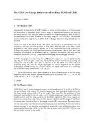
In <strong>the</strong> framework <strong>of</strong> <strong>the</strong> activities to prepare <strong>the</strong> future high-intensity proton beam for <strong>the</strong> <strong>CERN</strong> Neutrino<br />
to Gran Sasso (CNGS) Project [30], a critical review <strong>of</strong> <strong>the</strong> key processes used to generate such a beam<br />
was carried out [31], in view <strong>of</strong> a possible upgrade beyond <strong>the</strong> present nominal intensity value <strong>of</strong> about<br />
18
3.3×10 13 protons per PS batch. Among o<strong>the</strong>r issues, efforts were devoted to <strong>the</strong> improvement <strong>of</strong> <strong>the</strong><br />
present <strong>extraction</strong> scheme from <strong>the</strong> PS to <strong>the</strong> SPS, <strong>the</strong> Continuous Transfer.<br />
In <strong>the</strong> framework <strong>of</strong> <strong>the</strong> High Intensity <strong>Proton</strong>s Working Group (HIP-WG) [32] a detailed analysis<br />
<strong>of</strong> <strong>the</strong> losses for <strong>the</strong> beam for CNGS was performed [33]. The outcome is ra<strong>the</strong>r striking: for an overall<br />
intensity <strong>of</strong> about 4.5×10 19 protons/year required by <strong>the</strong> neutrino experiments, approximately 1.7×10 19 are<br />
lost in <strong>the</strong> accelerator chain, corresponding to about 40% <strong>of</strong> <strong>the</strong> total intensity. A large fraction <strong>of</strong> beam<br />
losses, namely 0.7×10 19 , or 40% <strong>of</strong> <strong>the</strong> total intensity lost occurs in <strong>the</strong> electrostatic septum <strong>of</strong> <strong>the</strong> PS ring<br />
used to slice <strong>the</strong> beam.<br />
In <strong>the</strong> quest for an improved <strong>extraction</strong> mode, a novel approach was proposed, named multi-turn<br />
<strong>extraction</strong> (MTE). In <strong>the</strong> new scenario <strong>the</strong> beam is separated in transverse phase space by generating<br />
stable islands inside <strong>the</strong> region where <strong>the</strong> beam sits and by slowly (adiabatically) moving <strong>the</strong>m towards<br />
higher amplitudes. By doing this, particles may get trapped inside islands thus generating well-separated<br />
beamlets [34]. This method is potentially superior to <strong>the</strong> present one as no intercepting device is used to<br />
split <strong>the</strong> beam; hence particle losses are limited to <strong>the</strong> fraction <strong>of</strong> <strong>the</strong> beam improperly deflected during<br />
<strong>the</strong> kicker rise time. Fur<strong>the</strong>rmore, <strong>the</strong> extracted beam should better match <strong>the</strong> phase space structure.<br />
6 Novel Multi-Turn Extraction<br />
6.1 Principle<br />
The novel technique relies on <strong>the</strong> use <strong>of</strong> non-linear magnetic fields (sextupolar and octupolar) to generate<br />
stable islands in <strong>the</strong> horizontal phase space [35]. By means <strong>of</strong> an appropriate tune variation, a specific<br />
resonance is crossed, <strong>the</strong> fourth-order in <strong>the</strong> case under study, and <strong>the</strong> beam is split by trapping inside <strong>the</strong><br />
stable islands moving from <strong>the</strong> origin <strong>of</strong> <strong>the</strong> phase space towards higher amplitudes [34]. A good model<br />
consists in choosing a simple FODO cell with a sextupole and an octupole located at <strong>the</strong> same<br />
longitudinal position, both represented in <strong>the</strong> single-kick approximation [36]. An example <strong>of</strong> <strong>the</strong> change<br />
<strong>of</strong> <strong>the</strong> phase space topology during resonance crossing is shown in Fig. 23.<br />
1<br />
(a)<br />
1<br />
(b)<br />
1<br />
(c)<br />
X’<br />
X’<br />
X’<br />
-1<br />
-1 X<br />
1<br />
-1<br />
-1 X<br />
1<br />
-1<br />
-1 X<br />
1<br />
Fig. 23: Topology <strong>of</strong> <strong>the</strong> normalized phase space during resonance crossing<br />
The evolution <strong>of</strong> <strong>the</strong> beam distribution during <strong>the</strong> resonance crossing is shown in Fig. 24.<br />
19
Fig. 24: Evolution <strong>of</strong> <strong>the</strong> beam distribution during resonance crossing. The initial state is represented<br />
by a bi-Gaussian beam (left), at resonance crossing some particles are trapped inside <strong>the</strong> moving<br />
islands (centre), at <strong>the</strong> end <strong>of</strong> <strong>the</strong> process, <strong>the</strong> particles trapped in <strong>the</strong> islands are moved towards higher<br />
amplitudes (right).<br />
When <strong>the</strong> tune is changed, <strong>the</strong> islands move through <strong>the</strong> phase space region where <strong>the</strong> charged<br />
particles sit and some are trapped inside <strong>the</strong> islands. At some stage a complete separation between <strong>the</strong><br />
beamlets and <strong>the</strong> central core occurs and <strong>the</strong> distance between <strong>the</strong> beamlets can be increased at will by<br />
simply acting on <strong>the</strong> tune. It is worth while stressing that <strong>the</strong> beam after trapping has a peculiar structure,<br />
i.e., it is made <strong>of</strong> two disconnected parts: <strong>the</strong> beamlets, which are indeed one single structure closing up<br />
after four turns around <strong>the</strong> machine (see Fig. 25), and <strong>the</strong> central core.<br />
The idea behind this process is that such a beam splitting in <strong>the</strong> transverse phase space can be used<br />
to perform multi-turn <strong>extraction</strong>. In fact, once <strong>the</strong> various beamlets are separated, <strong>the</strong> whole structure can<br />
be pushed towards an <strong>extraction</strong> septum by means <strong>of</strong> a closed slow bump. Then, kicker magnets generate<br />
a fast closed bump and one island jumps beyond <strong>the</strong> septum blade so that <strong>the</strong> beamlets are extracted out<br />
<strong>of</strong> <strong>the</strong> machine in four turns. The fifth beamlet, i.e., <strong>the</strong> beam core, is extracted using a classical singleturn<br />
<strong>extraction</strong>. The advantage <strong>of</strong> this approach is that, at least for <strong>the</strong> first four turns, <strong>the</strong> optical<br />
parameters are, by definition, <strong>the</strong> same. This is intrinsic to <strong>the</strong> method, as <strong>the</strong> same stable island is used to<br />
extract <strong>the</strong> beam.<br />
It is worth stressing that numerical simulations are performed by crossing <strong>the</strong> resonance from<br />
above: this is <strong>the</strong> opposite <strong>of</strong> what is done in <strong>the</strong> experimental tests, where <strong>the</strong> resonance is crossed from<br />
below. The choice <strong>of</strong> <strong>the</strong> resonance to be crossed is completely arbitrary as <strong>the</strong> use <strong>of</strong> a fourth-order<br />
resonance is dictated only by <strong>the</strong> <strong>CERN</strong>-specific application (see Refs. [37, 38] for a generalization to<br />
o<strong>the</strong>r types <strong>of</strong> resonance and to injection, respectively).<br />
6.2 Measurement results<br />
6.2.1 Overall measurement strategy<br />
In parallel with <strong>the</strong> computational and <strong>the</strong>oretical analysis, an intense experimental campaign was<br />
launched at <strong>the</strong> end <strong>of</strong> 2001 on <strong>the</strong> <strong>CERN</strong> PS (see Ref. [39] for <strong>the</strong> final account <strong>of</strong> <strong>the</strong> results achieved).<br />
This entailed <strong>the</strong> development <strong>of</strong> new measurement systems, such as <strong>the</strong> turn-by-turn orbit measurement<br />
system [40, 41], as well as <strong>the</strong> installation <strong>of</strong> sextupoles and octupoles to generate <strong>the</strong> stable islands.<br />
20
Fig. 25: 3D view <strong>of</strong> <strong>the</strong> beamlets along <strong>the</strong> circumference <strong>of</strong> <strong>the</strong> PS machine. The fifth beamlet, i.e.,<br />
<strong>the</strong> beam core, is not shown here.<br />
The magnetic elements and <strong>the</strong> beam instrumentation used in <strong>the</strong> experimental campaign are shown<br />
in Fig. 26 (left). The tune is changed by means <strong>of</strong> <strong>the</strong> two families <strong>of</strong> focusing and defocusing<br />
quadrupoles, normally used to control <strong>the</strong> machine at low energy. Sextupoles and octupoles are used to<br />
generate <strong>the</strong> stable islands; <strong>the</strong> fast-<strong>extraction</strong> kicker is used to displace <strong>the</strong> beam and induce betatron<br />
oscillations for phase space measurements; a wire scanner [42] is used to measure <strong>the</strong> horizontal beam<br />
pr<strong>of</strong>ile (see Fig. 26 – right – for details on <strong>the</strong> installation); two pick-ups are used to record <strong>the</strong> betatron<br />
oscillations.<br />
Trapping measurements with a high-intensity beam represented <strong>the</strong> most important test for this<br />
novel approach. A sequence <strong>of</strong> transverse beam pr<strong>of</strong>iles during <strong>the</strong> splitting process is shown in Fig. 27<br />
(upper part) toge<strong>the</strong>r with <strong>the</strong> best result achieved (lower part). The intensity as a function <strong>of</strong> time is<br />
shown (lower left). The injected intensity is slightly above 6×10 12 protons and small losses are visible up<br />
to transition crossing (second vertical red line). Then, <strong>the</strong> intensity stays remarkably constant up to<br />
<strong>extraction</strong>, which is performed by means <strong>of</strong> a kicker in a single turn after having merged back <strong>the</strong><br />
beamlets in order to reduce <strong>the</strong> beam size in <strong>the</strong> horizontal plane to match <strong>the</strong> septum acceptance. The<br />
beam distribution as measured in <strong>the</strong> transfer line downstream <strong>of</strong> <strong>the</strong> <strong>extraction</strong> point from <strong>the</strong> PS<br />
machine is shown in Fig. 27 (lower right). Optical Transition Radiation (OTR) [43] is used to record <strong>the</strong><br />
two-dimensional beam distribution in physical space. The peculiar shape <strong>of</strong> <strong>the</strong> beam distribution is<br />
clearly visible: <strong>the</strong> two lateral peaks represent <strong>the</strong> projection in physical space <strong>of</strong> <strong>the</strong> beamlets.<br />
A final test was performed to increase <strong>the</strong> fraction <strong>of</strong> particles trapped inside <strong>the</strong> islands. For this<br />
study, a special setting <strong>of</strong> <strong>the</strong> octupoles was programmed: instead <strong>of</strong> keeping <strong>the</strong>ir strength constant all<br />
along <strong>the</strong> resonance-crossing phase, <strong>the</strong> current was suddenly increased just before resonance crossing<br />
and <strong>the</strong>n gradually reduced. This should generate large islands at small amplitudes thus trapping more<br />
particles from <strong>the</strong> region where <strong>the</strong> density is high, and <strong>the</strong>n keeping almost constant <strong>the</strong> island’s size.<br />
The results are shown in Fig. 28, where <strong>the</strong> current as a function <strong>of</strong> time for both <strong>the</strong> sextupoles and <strong>the</strong><br />
octupoles is shown (left) as well as <strong>the</strong> measured horizontal beam pr<strong>of</strong>ile (right).<br />
21
Section 54<br />
Section 55<br />
Section 21<br />
Section 20<br />
Extraction line<br />
Flying wires<br />
Sextupole magnets<br />
Kicker magnet<br />
Octupole magnets<br />
Slow bump<br />
Extraction<br />
septum<br />
Section 16<br />
Section 64<br />
Section 71<br />
Fig. 26: Schematic layout <strong>of</strong> <strong>the</strong> PS machine with <strong>the</strong> elements used for <strong>the</strong> experimental study <strong>of</strong> <strong>the</strong><br />
novel multi-turn <strong>extraction</strong> (left). Schematic layout <strong>of</strong> <strong>the</strong> mechanism <strong>of</strong> <strong>the</strong> PS wire scanner (upper<br />
right). The installation <strong>of</strong> <strong>the</strong> scintillators on both sides <strong>of</strong> <strong>the</strong> vacuum pipe is also shown (lower<br />
right).<br />
Under <strong>the</strong>se new conditions it was indeed possible to increase <strong>the</strong> fraction <strong>of</strong> particles inside <strong>the</strong><br />
islands, achieving a value <strong>of</strong> 18% against a previous value <strong>of</strong> about 13%. It is worth while mentioning<br />
that for <strong>the</strong> optimal performance <strong>of</strong> <strong>the</strong> SPS machine, <strong>the</strong> tolerance for <strong>the</strong> fraction <strong>of</strong> particles in each<br />
beamlet is (20±5)%. Therefore, if this needs to hold for <strong>the</strong> central core, <strong>the</strong>n, <strong>the</strong> four beamlets should<br />
satisfy <strong>the</strong> tighter limit (20±1)% as any deviation in beamlets intensity is reflected on <strong>the</strong> core amplified<br />
by a factor <strong>of</strong> four. However, <strong>the</strong> price to pay was <strong>the</strong> presence <strong>of</strong> slightly higher losses during resonance<br />
crossing up to <strong>the</strong> level <strong>of</strong> 2%–3% <strong>of</strong> <strong>the</strong> total beam intensity.<br />
The main parameters <strong>of</strong> <strong>the</strong> single-bunch beams used in <strong>the</strong> experimental campaign are<br />
summarized in Table 1.<br />
Table 1: Parameters <strong>of</strong> <strong>the</strong> single-bunch beams used for <strong>the</strong> experimental tests <strong>of</strong> <strong>the</strong> novel multi-turn<br />
<strong>extraction</strong>. The emittance is <strong>the</strong> normalized, one-sigma value.<br />
Parameter<br />
Intensity<br />
(protons/bunch)<br />
ε* H (σ)<br />
(μm)<br />
ε* V (σ)<br />
(μm)<br />
Δp/p (σ)<br />
10 −3<br />
Low-intensity, pencil beam 5×10 11 2.3 1.3 0.25<br />
Low-intensity, large horizontal emittance 5×10 11 6.2 1.6 0.25<br />
High-intensity beam 6×10 12 9.4 6.4 0.60<br />
22
Fig. 27: Sequence <strong>of</strong> beam pr<strong>of</strong>ile during splitting (upper) and best result achieved with a highintensity<br />
beam, whose intensity as a function <strong>of</strong> time (lower left). Two-dimensional beam distribution<br />
in physical space <strong>of</strong> <strong>the</strong> beam in <strong>the</strong> transfer line downstream <strong>of</strong> <strong>the</strong> PS <strong>extraction</strong> point (lower right).<br />
Current (A)<br />
300<br />
200<br />
100<br />
Free parameter during<br />
sextupole scan<br />
0<br />
150 350 550 750 950 1150<br />
-100<br />
Time (ms)<br />
-200<br />
-300<br />
-400<br />
-500<br />
Octupole Sextupole Magnetic field<br />
Beginning <strong>of</strong><br />
magnetic flat-top<br />
Injection<br />
Pr<strong>of</strong>ile<br />
measurement<br />
Free parameter during octupole scan<br />
0.7<br />
0.6<br />
0.5<br />
0.4<br />
0.3<br />
0.2<br />
0.1<br />
0.0<br />
Magnetic field (T)<br />
Fig. 28: Current as a function <strong>of</strong> time for <strong>the</strong> sextupoles and octupoles as used in <strong>the</strong> special test to<br />
increase <strong>the</strong> fraction <strong>of</strong> particles trapped in <strong>the</strong> beamlets (left). The resulting horizontal beam pr<strong>of</strong>ile<br />
after splitting is also shown (right). The pr<strong>of</strong>ile is not centred at zero due to an instrumental <strong>of</strong>fset <strong>of</strong><br />
<strong>the</strong> wire position.<br />
23
7 Implementation <strong>of</strong> MTE at <strong>the</strong> <strong>CERN</strong> PS<br />
7.1 Design principle<br />
The experimental campaign was completed at <strong>the</strong> end <strong>of</strong> 2004. The analysis <strong>of</strong> <strong>the</strong> required modifications<br />
to implement <strong>the</strong> proposed multi-turn <strong>extraction</strong> took place during <strong>the</strong> 2005/2006 long shutdown <strong>of</strong> <strong>the</strong><br />
PS machine. The conceptual design <strong>of</strong> <strong>the</strong> proposed multi-turn <strong>extraction</strong> can be sketched as follows (see<br />
Ref. [44] for more details and Ref. [45] for a complete account <strong>of</strong> <strong>the</strong> hardware commissioning):<br />
– <strong>Beam</strong> splitting: two pairs <strong>of</strong> two sextupoles and one octupole each will separate <strong>the</strong> initial<br />
single beam into <strong>the</strong> five beamlets prior to <strong>extraction</strong>. Contrary to <strong>the</strong> experimental set-up,<br />
where only one set <strong>of</strong> two sextupoles and one octupole was used, <strong>the</strong> choice <strong>of</strong> two pairs is<br />
mainly dictated by <strong>the</strong> need to control and adjust <strong>the</strong> phase <strong>of</strong> <strong>the</strong> islands at <strong>the</strong> <strong>extraction</strong> point.<br />
– Extraction: <strong>the</strong> <strong>extraction</strong> point is in SS16, where <strong>the</strong> magnetic septum for <strong>the</strong> beam <strong>extraction</strong><br />
towards <strong>the</strong> SPS is located. In <strong>the</strong> proposed scheme, <strong>the</strong> electrostatic septum, currently used to<br />
slice <strong>the</strong> beam in <strong>the</strong> context <strong>of</strong> <strong>the</strong> CT <strong>extraction</strong> in SS31, is not required, thus simplifying <strong>the</strong><br />
overall scheme. Two bumps will be used to displace <strong>the</strong> beam towards <strong>the</strong> magnetic septum<br />
blade (slow bump) and to extract <strong>the</strong> beamlets over five turns (fast bump).<br />
– Slow bump: a set <strong>of</strong> dipole magnets (bumpers) will be used to generate <strong>the</strong> slow bump around<br />
<strong>the</strong> magnetic septum. Currently, four bumps powered with a series/parallel circuit are used to<br />
extract <strong>the</strong> beams towards <strong>the</strong> SPS. In <strong>the</strong> proposed scheme, six independently powered<br />
magnets are foreseen. The large number <strong>of</strong> bumpers is imposed by <strong>the</strong> aperture constraints, as it<br />
will allow a careful shaping <strong>of</strong> <strong>the</strong> bump to overcome <strong>the</strong> potential aperture bottlenecks.<br />
– Fast bump: three new kickers will generate <strong>the</strong> fast bump used to displace <strong>the</strong> beam beyond <strong>the</strong><br />
blade <strong>of</strong> <strong>the</strong> magnetic septum. The pulse length should correspond to five PS turns. Since <strong>the</strong><br />
centre core <strong>of</strong> <strong>the</strong> beam needs to be ejected, an additional kick will have to be imparted at <strong>the</strong><br />
fifth turn. For this <strong>the</strong> fast <strong>extraction</strong> kicker will be used.<br />
– Trajectory correction in <strong>the</strong> transfer line towards <strong>the</strong> SPS: even though <strong>the</strong> <strong>extraction</strong> conditions<br />
for <strong>the</strong> novel multi-turn <strong>extraction</strong> do not change from turn to turn, as one single island is used<br />
to extract <strong>the</strong> beam, <strong>the</strong> feed-down effects <strong>of</strong> <strong>the</strong> machine non-linearities (particularly from <strong>the</strong><br />
pole face windings in <strong>the</strong> main magnets) due to <strong>the</strong> <strong>extraction</strong> bumps could generate turn-byturn<br />
variation <strong>of</strong> <strong>the</strong> beamlet position at PS <strong>extraction</strong>. Such an effect could have a negative<br />
impact on <strong>the</strong> emittance after filamentation in <strong>the</strong> SPS. Hence two kickers capable <strong>of</strong> generating<br />
deflection changing from turn to turn will be used in <strong>the</strong> TT2 transfer line to correct for <strong>the</strong><br />
variation in <strong>the</strong> <strong>extraction</strong> conditions (position and angle). These two devices are already being<br />
used for <strong>the</strong> CT <strong>extraction</strong> mode.<br />
7.2 Implementation<br />
The implementation <strong>of</strong> MTE required different interventions, such as design, production, and installation<br />
<strong>of</strong> new octupoles; construction <strong>of</strong> new power converters for <strong>the</strong> new <strong>extraction</strong> bump; design,<br />
construction, and installation <strong>of</strong> new vacuum chambers for increasing <strong>the</strong> beam aperture in particular in<br />
<strong>the</strong> <strong>extraction</strong> region; construction <strong>of</strong> new <strong>extraction</strong> kickers and <strong>the</strong>ir Pulse Forming Network (PFN). A<br />
large fraction <strong>of</strong> <strong>the</strong> PS circumference was affected by those interventions, summarized in Fig. 29, and<br />
24
<strong>the</strong>y were done over two consecutive winter shutdown periods 2006/2007 and 2007/2008, <strong>the</strong> peak <strong>of</strong><br />
activities occurring during <strong>the</strong> 2007/2008 shutdown.<br />
Fig. 29: Summary <strong>of</strong> <strong>the</strong> hardware interventions related to <strong>the</strong> MTE installation<br />
7.2.1 Slow bump<br />
The original version <strong>of</strong> <strong>the</strong> slow bump in section 16 was made <strong>of</strong> four magnets located in SS12, 14, 20,<br />
and 22. The elements in SS12 and 22 were connected in series as well as those in SS14 and 20, <strong>the</strong> two<br />
groups being <strong>the</strong>n connected in parallel to a single power converter.<br />
Bump amplitude (mm)<br />
70<br />
60<br />
50<br />
40<br />
30<br />
20<br />
10<br />
Origin <strong>of</strong> s coordinate: SS54<br />
Slow bump for CT<br />
Slow bump for MTE<br />
0<br />
0<br />
-10<br />
100 200 300 400 500 600 700<br />
-20<br />
s coordinate (m)<br />
Fig. 30: Amplitude <strong>of</strong> closed bump 16 all along <strong>the</strong> circumference <strong>of</strong> <strong>the</strong> PS machine for both <strong>the</strong><br />
original version based on <strong>the</strong> use <strong>of</strong> four dipoles and <strong>the</strong> current one based on six dipoles<br />
For MTE <strong>the</strong> layout <strong>of</strong> <strong>the</strong> slow bump 16 was modified so that six magnets (those already installed<br />
plus two in SS15 and in SS18) will each be powered by a dedicated power converter. The shape <strong>of</strong> <strong>the</strong><br />
25
ump in its present configuration and in <strong>the</strong> proposed one is shown in Fig. 30. The non-closure <strong>of</strong> <strong>the</strong><br />
original version <strong>of</strong> <strong>the</strong> slow bump is corrected by <strong>the</strong> larger number <strong>of</strong> independent correctors.<br />
It is worth mentioning that <strong>the</strong> new version <strong>of</strong> <strong>the</strong> slow bump entails a number <strong>of</strong> changes also at<br />
<strong>the</strong> level <strong>of</strong> <strong>the</strong> power converters [44].<br />
7.2.2 Fast bump<br />
The MTE scheme is based on a fast bump around <strong>the</strong> magnetic septum in SS16 (see Fig. 31, top).<br />
Bump amplitude (mm)<br />
60<br />
50<br />
40<br />
30<br />
20<br />
10<br />
0<br />
-10<br />
Origin <strong>of</strong> s coordinate: SS54<br />
0 100 200 300 400 500 600 700<br />
s coordinate (m)<br />
Fig. 31: Top: PS Complex layout, indicating <strong>the</strong> location <strong>of</strong> <strong>the</strong> fast pulsed magnets (red dots) and <strong>the</strong><br />
magnetic septum in SS16 (blue dot) implied in <strong>the</strong> new PS multi-turn <strong>extraction</strong> scheme. The elements<br />
named DFA correspond to <strong>the</strong> devices called ERD. Bottom: Example <strong>of</strong> <strong>the</strong> bump generated by <strong>the</strong><br />
new kickers for <strong>the</strong> <strong>extraction</strong> <strong>of</strong> <strong>the</strong> fifth turn, i.e., <strong>the</strong> beam core<br />
26
Fast pulsed magnets (kickers), to be located in SS13 and SS21, will create a nearly closed bump for<br />
<strong>the</strong> beamlets in <strong>the</strong> first four turns. To close it perfectly, an existing kicker in SS09 will be used. The core<br />
beam needs to be moved out by more than twice <strong>the</strong> distance <strong>of</strong> <strong>the</strong> o<strong>the</strong>r four beamlets. One additional<br />
kicker, to be located in SS04, in conjunction with <strong>the</strong> existing KFA71–79 system will kick out <strong>the</strong><br />
remaining beam in <strong>the</strong> fifth turn. Two existing emittance reduction fast dipoles in <strong>the</strong> TT2 transfer line<br />
will be used to correct <strong>the</strong> trajectory <strong>of</strong> <strong>the</strong> beamlets. As an example, <strong>the</strong> fast bump generated by <strong>the</strong><br />
kickers for <strong>the</strong> <strong>extraction</strong> <strong>of</strong> <strong>the</strong> fifth turn is shown in Fig. 31 (bottom).<br />
The turn-by-turn variation <strong>of</strong> <strong>the</strong> <strong>extraction</strong> conditions will be corrected by dedicated kickers in <strong>the</strong><br />
TT2 transfer line. The new system re-uses a maximum <strong>of</strong> existing de-commissioned and reserve<br />
equipment to minimize delays and reduce <strong>the</strong> cost.<br />
A summary <strong>of</strong> <strong>the</strong> main parameters <strong>of</strong> <strong>the</strong> PS ring kickers is given in Table 2.<br />
Table 2: Required kicker strength and rise time values (10% and 90%). The strengths are computed for a beam<br />
rigidity <strong>of</strong> 46.68 Tm.<br />
Turn<br />
BFA9<br />
(mrad)<br />
KFA13<br />
(mrad)<br />
KFA21<br />
(mrad)<br />
KFA71<br />
(mrad)<br />
KFA4<br />
(mrad)<br />
1 −0.114 1.839 1.887 0 0<br />
2 −0.114 1.839 1.887 0 0<br />
3 −0.114 1.839 1.887 0 0<br />
4 −0.114 1.839 1.887 0 0<br />
5 −0.114 1.839 1.887 −1.834 −0.400<br />
Rise time (ns) 340 350 350 70 80<br />
Maximum strength (kV) 35 80 80 9×80 80<br />
7.2.3 Sextupoles and octupoles<br />
The creation <strong>of</strong> stable islands is possible by setting <strong>the</strong> linear and non-linear magnetic components in <strong>the</strong><br />
PS ring. This is achieved by acting on <strong>the</strong> pole-face windings, figure-<strong>of</strong>-eight loop, plus four sextupoles<br />
and two octupoles dedicated to MTE operation. Whereas <strong>the</strong> four sextupoles already existed, three new<br />
octupoles, two operative magnets plus one spare, have been designed, constructed, magnetically<br />
measured, and <strong>the</strong>n installed. The octupolar gradient difference between <strong>the</strong> three magnets is well below<br />
<strong>the</strong> 0.3%, as shown in Fig. 32 (left), where also <strong>the</strong> octupolar gradients versus current are presented. The<br />
magnet saturation occurs at about 500 A. Two octupoles have been installed, one in SS39 and <strong>the</strong> o<strong>the</strong>r<br />
SS55, in a tightly packed installation toge<strong>the</strong>r with two sextupoles, shown in Fig. 32 (right).<br />
27
Fig. 32: Measured gradient <strong>of</strong> <strong>the</strong> three octupoles available for installation (left). Picture <strong>of</strong> <strong>the</strong> SS39<br />
(right). The two yellow sextupoles are interleaved by <strong>the</strong> violet octupole.<br />
7.2.4 Optimization <strong>of</strong> <strong>the</strong> aperture<br />
A crucial issue for <strong>the</strong> implementation <strong>of</strong> MTE is <strong>the</strong> available mechanical aperture. On account <strong>of</strong> <strong>the</strong><br />
principle, once <strong>the</strong> beam is split, <strong>the</strong>re will be five beamlets circulating in <strong>the</strong> ring with different closed<br />
orbits. This increases <strong>the</strong> required aperture, in particular in <strong>the</strong> <strong>extraction</strong> region.<br />
The changes implemented during <strong>the</strong> installation <strong>of</strong> MTE are concentrated in straight sections in<br />
<strong>the</strong> neighbourhood <strong>of</strong> SS16 and <strong>the</strong>y are aimed at accommodating <strong>the</strong> five beamlets without any beam<br />
losses. As an example, <strong>the</strong> original and <strong>the</strong> new layout <strong>of</strong> <strong>the</strong> vacuum chamber installed in <strong>the</strong> magnet unit<br />
16 are shown in Fig. 33. The main improvement refers to <strong>the</strong> increase <strong>of</strong> <strong>the</strong> cross-section for <strong>the</strong> part <strong>of</strong><br />
<strong>the</strong> vacuum chamber dedicated to <strong>the</strong> circulating beam. Fur<strong>the</strong>rmore, <strong>the</strong> longitudinal extension <strong>of</strong> <strong>the</strong><br />
region where circulating and extracted beams share <strong>the</strong> same aperture was increased.<br />
Fig. 33: Layout <strong>of</strong> <strong>the</strong> new vacuum chamber in magnet unit 16 (lower part). The chamber originally<br />
installed is also shown (upper part).<br />
The available aperture in <strong>the</strong> <strong>extraction</strong> region is shown in Fig. 34. In <strong>the</strong> upper part <strong>the</strong> cross<br />
section <strong>of</strong> <strong>the</strong> new vacuum chamber in magnet unit 15 is shown toge<strong>the</strong>r with <strong>the</strong> beam envelope at<br />
3 σ, represented by <strong>the</strong> rectangles, with <strong>the</strong> slow and fast bumps switched on. In <strong>the</strong> lower part <strong>the</strong> same<br />
situation is represented as a function <strong>of</strong> beam trajectory.<br />
28
Fig. 34: Upper: Cross-section <strong>of</strong> <strong>the</strong> new vacuum chamber in magnet unit 15 toge<strong>the</strong>r with <strong>the</strong><br />
transverse sections <strong>of</strong> <strong>the</strong> beamlets at <strong>extraction</strong>. The units for both axes are millimetres. Lower:<br />
Superposition <strong>of</strong> <strong>the</strong> horizontal beam envelope for <strong>the</strong> five beamlets at <strong>extraction</strong>, i.e., when both <strong>the</strong><br />
slow and fast bumps are switched on. Only a subset <strong>of</strong> <strong>the</strong> PS circumference in <strong>the</strong> neighbourhood <strong>of</strong><br />
<strong>the</strong> <strong>extraction</strong> point is shown. The main magnet identification numbers are shown on <strong>the</strong> top.<br />
8 MTE beam commissioning in 2008 and 2009<br />
After <strong>the</strong> completion <strong>of</strong> <strong>the</strong> installation phase during <strong>the</strong> winter shutdown 2007/2008, <strong>the</strong> hardware and<br />
beam commissioning started in <strong>the</strong> 2008 PS run. Here, <strong>the</strong> milestones will be recorded, <strong>the</strong> details being<br />
available in Refs. [45–47].<br />
The first half <strong>of</strong> 2008 was devoted to <strong>the</strong> hardware commissioning and <strong>the</strong> setting up <strong>of</strong> <strong>the</strong> beam<br />
splitting with <strong>the</strong> new hardware [45].<br />
The first MTE <strong>extraction</strong> was performed on 1 August 2008, when a single-bunch beam <strong>of</strong> about 3×10 12<br />
protons was sent to an external dump in <strong>the</strong> PS–SPS transfer line.<br />
Figure 35 (left) shows <strong>the</strong> measured horizontal beam pr<strong>of</strong>ile <strong>of</strong> <strong>the</strong> beamlets in <strong>the</strong> PS at <strong>the</strong> end <strong>of</strong><br />
<strong>the</strong> splitting process and prior to <strong>extraction</strong>. A fit <strong>of</strong> <strong>the</strong> five beamlets is also superimposed. Figure 35<br />
(right) shows <strong>the</strong> intensity signal <strong>of</strong> a pick-up in <strong>the</strong> PS–SPS transfer line <strong>of</strong> <strong>the</strong> extracted beam. Each <strong>of</strong><br />
<strong>the</strong> five peaks corresponds to a beamlet extracted over a single turn. The distance between <strong>the</strong>m<br />
corresponds to <strong>the</strong> PS revolution time <strong>of</strong> 2.1 µs. As expected, <strong>the</strong> five peaks feature about <strong>the</strong> same<br />
intensity, a clear sign that <strong>the</strong> equally populated islands were correctly extracted.<br />
29
Fig. 35: Transverse pr<strong>of</strong>ile <strong>of</strong> <strong>the</strong> beamlets before <strong>extraction</strong> (left) and intensity signal <strong>of</strong> a pick-up in<br />
<strong>the</strong> PS–SPS transfer line <strong>of</strong> <strong>the</strong> extracted beam<br />
The rest <strong>of</strong> <strong>the</strong> commissioning period in 2008 was devoted to <strong>the</strong> preparation <strong>of</strong> <strong>the</strong> operational<br />
magnetic cycle, <strong>the</strong> study <strong>of</strong> <strong>the</strong> <strong>extraction</strong> with multi-bunch beam, and <strong>the</strong> determination <strong>of</strong> <strong>the</strong> most<br />
suitable longitudinal structure to be injected in <strong>the</strong> SPS. This has been ano<strong>the</strong>r crucial point <strong>of</strong> <strong>the</strong> study.<br />
The beamlet formation, in fact, is not sensitive to <strong>the</strong> number <strong>of</strong> bunches in <strong>the</strong> machine, but it is sensitive<br />
to <strong>the</strong> beam momentum spread, since via chromaticity a large momentum spread creates a large tune<br />
modulation, inducing trapping/de-trapping phenomena and reducing <strong>the</strong> capture efficiency. The losses at<br />
<strong>extraction</strong>, however, depend on <strong>the</strong> bunch spacing due to <strong>the</strong> finite rise time <strong>of</strong> <strong>the</strong> kickers. In particular,<br />
<strong>the</strong> kicker rise time is longer than <strong>the</strong> h=8 PS bunch spacing, <strong>the</strong> rise time being about 350 ns and <strong>the</strong><br />
bunch spacing about 260 ns. This implies that a fraction <strong>of</strong> <strong>the</strong> beam will be intercepted by <strong>the</strong> <strong>extraction</strong><br />
septum during <strong>the</strong> kicker rise. The situation becomes worse if <strong>the</strong> h=16 harmonic is preferred or if <strong>the</strong><br />
beam is de-bunched: <strong>the</strong> losses are nearly doubled going from 0.6% <strong>of</strong> <strong>the</strong> circulating intensity for h=8 up<br />
to 0.9% and 1% for <strong>the</strong> h=16 and de-bunched cases, respectively [44]. A detailed series <strong>of</strong> studies has<br />
been made by injecting a beam in <strong>the</strong> SPS with different longitudinal structures from <strong>the</strong> PS and assessing<br />
<strong>the</strong> dependence <strong>of</strong> <strong>the</strong> losses as a function <strong>of</strong> <strong>the</strong> harmonic number and <strong>of</strong> <strong>the</strong> RF voltage at <strong>extraction</strong>.<br />
The conclusion was that a de-bunched beam is <strong>the</strong> most suitable for <strong>the</strong> SPS, even if this choice does not<br />
minimize <strong>the</strong> losses in <strong>the</strong> PS. Hence, a MTE de-bunched <strong>extraction</strong>, see Fig. 36 (left), was prepared after<br />
<strong>the</strong> end <strong>of</strong> <strong>the</strong> 2008 SPS run, increasing <strong>the</strong> extracted intensity to 1.4×10 13 protons. The <strong>extraction</strong><br />
efficiency, expected to be up to 97–98 %, turned out to be on average about 93%, but with peaks up to<br />
99%. These fluctuations were correlated with beam instability due to a slightly negative value <strong>of</strong> <strong>the</strong><br />
chromaticity just prior to <strong>the</strong> resonant crossing. For <strong>the</strong> nominal <strong>extraction</strong> case, with an efficiency <strong>of</strong><br />
about 98%, <strong>the</strong> beam loss pattern was compared with <strong>the</strong> five-turn <strong>extraction</strong> currently in use [48]. As<br />
expected, (see Fig. 36, right), <strong>the</strong> MTE beam losses are concentrated in <strong>the</strong> <strong>extraction</strong> region, whereas for<br />
<strong>the</strong> CT, losses <strong>of</strong> typically 5–6% <strong>of</strong> <strong>the</strong> circulating intensity are spread out over <strong>the</strong> entire machine<br />
circumference [48]. These losses are generated by <strong>the</strong> interaction <strong>of</strong> protons with <strong>the</strong> blade <strong>of</strong> <strong>the</strong><br />
electrostatic septum in SS31. Moreover, particles scattered at <strong>the</strong> septum generate losses in <strong>the</strong> region<br />
between SS40–45 and SS72–76.<br />
During <strong>the</strong> last part <strong>of</strong> <strong>the</strong> CNGS run, it was possible to inject a MTE, h=16 bunched beam in one<br />
<strong>of</strong> <strong>the</strong> CNGS SPS cycles. The total intensity injected was about 1.4×10 13 protons. The two batches, each<br />
one <strong>of</strong> about 0.7×10 13 protons, had <strong>the</strong> last PS ejected turn with a larger intensity than <strong>the</strong> o<strong>the</strong>r four. The<br />
proton beam in <strong>the</strong> SPS could be injected, accelerated, and extracted towards <strong>the</strong> CNGS target. Neutrinos<br />
were also produced during <strong>the</strong> last night <strong>of</strong> <strong>the</strong> 2008 CNGS run.<br />
30
Fig. 36: Intensity <strong>of</strong> a MTE de-bunched beam extracted over five turns measured by a transformer in<br />
<strong>the</strong> PS–SPS transfer line (left). <strong>Beam</strong> losses at each PS straight section for <strong>the</strong> MTE beam compared<br />
to a CT extracted beam (fixed target physics) for <strong>the</strong> same intensity (right). The sizeable reduction is<br />
apparent.<br />
The target for <strong>the</strong> 2009 physics run was to complete <strong>the</strong> commissioning, in particular cure <strong>the</strong><br />
instability and <strong>the</strong> ensuing emittance blow-up, prepare a debunched version <strong>of</strong> <strong>the</strong> MTE beam, and<br />
improve <strong>the</strong> beam sharing among <strong>the</strong> five beamlets. In <strong>the</strong> second half <strong>of</strong> <strong>the</strong> 2009 run it was possible to<br />
deliver a beam to <strong>the</strong> SPS for one <strong>of</strong> <strong>the</strong> CNGS cycles. The intensity delivered was about 1.6×10 13 p per<br />
PS <strong>extraction</strong>. By <strong>the</strong> end <strong>of</strong> <strong>the</strong> 2009 CNGS run about 4.7×10 17 p were delivered via <strong>the</strong> MTE beam.<br />
The intensity sharing was improved continuously during <strong>the</strong> 2009 run, introducing <strong>the</strong> correction <strong>of</strong><br />
<strong>the</strong> non-linear coupling generated by <strong>the</strong> MTE octupoles, using <strong>the</strong> string <strong>of</strong> octupoles normally used to<br />
combat beam instabilities. Then, <strong>the</strong> last bit was achieved by means <strong>of</strong> <strong>the</strong> transverse damper that<br />
improved <strong>the</strong> sharing so that <strong>the</strong> target <strong>of</strong> 20% was reached. In Fig. 37 <strong>the</strong> impact <strong>of</strong> <strong>the</strong> beam excitation<br />
via a signal generated syn<strong>the</strong>tically and sent to <strong>the</strong> damper kicker is clearly seen.<br />
Intensity (10 10 )<br />
20<br />
18<br />
16<br />
14<br />
12<br />
10<br />
8<br />
6<br />
4<br />
2<br />
Single frequency (average over 16 data sets)<br />
No excitation (1 data set)<br />
Noise (average over 9 data sets)<br />
0<br />
836.001 836.003 836.005 836.007 836.009 836.011 836.013<br />
Time (ms)<br />
Fig. 37: Extracted spill pr<strong>of</strong>ile for no beam excitation, excitation with a single frequency at <strong>the</strong> tune<br />
value, excitation at <strong>the</strong> tune value with noise. The difference is apparent.<br />
It is worth mentioning that a number <strong>of</strong> instabilities (microwave, and coupled-bunch longitudinal <strong>of</strong><br />
quadrupolar mode) were observed during <strong>the</strong> MTE commissioning in 2009. The first one required <strong>the</strong><br />
beam to be debunched only at <strong>the</strong> very end, just prior to <strong>extraction</strong>, as can be seen in Fig. 38.<br />
31
Fig. 38: Magnetic field (black) and RF voltage (h=8, blue; h=16, red) for <strong>the</strong> whole magnetic cycle.<br />
The shaded area corresponds to <strong>the</strong> transverse splitting gymnastics.<br />
References<br />
[1] A. Citron, On a possible ejection scheme, <strong>CERN</strong> PS/AC-5 (1954).<br />
[2] B. Kuiper and G. Plass, On <strong>the</strong> Fast Extraction <strong>of</strong> Particles from a 25 GeV <strong>Synchrotron</strong>, <strong>CERN</strong> 59-30<br />
(1959).<br />
[3] R. Bertolotto, H. Van Breugel, L. Caris, E. Consigny, H. Dijkhuisen, J. Goni, J. J. Hirsbrunner,<br />
B. Kuiper, S. Milner, S. Pichler, and G. Plass, The fast ejection system <strong>of</strong> <strong>the</strong> <strong>CERN</strong> 25 GeV Protron<br />
<strong>Synchrotron</strong>, in Proceedings <strong>of</strong> <strong>the</strong> Fourth International Conference on High-Energy Accelerators,<br />
Dubna, Soviet Union, 1963, edited by A. Kolomenskij, A. B. Kuznetsov and A. N. Lebedev<br />
(Atomizdat, Moscow, 1964), p. 869.<br />
[4] R. Bossart, H. Van Breugel, L. Caris, H. Dijkhuisen, I. Kamber, B. Kuiper, J. Leroux, S. Milner,<br />
B. Nicolai, and E. M. Williams, Multishot and multichannel fast ejection, IEEE Trans. Nucl. Sci. 16<br />
(1969) 286.<br />
[5] K. Hübner, 50 years <strong>of</strong> research at <strong>CERN</strong>, from past to future: <strong>the</strong> accelerators, in <strong>CERN</strong>-2006-004<br />
(2006), pp. 1–26 and <strong>CERN</strong>-AB-2005-031 (2005).<br />
[6] D. Fiander, Hardware for a full aperture kicker system for <strong>the</strong> CPS, in Proceedings <strong>of</strong> <strong>the</strong> 1971 Particle<br />
Accelerator Conference, Chicago, Ill., USA, 1971, 1022–3.<br />
[7] R. L. Keizer, Dipole Septum Magnets, <strong>CERN</strong> 74-13 (1974).<br />
[8] J. Borburgh, M. Hourican, and M. Thivent, A new set <strong>of</strong> magnetic septa in <strong>the</strong> <strong>CERN</strong> PS complex, in<br />
Proceedings <strong>of</strong> <strong>the</strong> 1999 Particle Accelerator Conference, New York, NY, USA, 2283–5.<br />
[9] H. G. Hereward, The possibility <strong>of</strong> resonant <strong>extraction</strong> from <strong>the</strong> CPS, AR/Int. GS/61-5 (1961).<br />
[10] H. G. Hereward, The CPS resonant <strong>extraction</strong> system, in Proceedings <strong>of</strong> <strong>the</strong> Fourth International<br />
Conference on High Energy Accelerators, Dubna, Soviet Union, 1963, edited by A. Kolomenskij,<br />
A. B. Kuznetsov, and A. N. Lebedev (Atomizdat, Moscow, 1964), p. 690.<br />
[11] C. Bovet, G. R. Lambertson, and K. H. Reich, Measurements on Slow <strong>Beam</strong>-Ejection from <strong>the</strong> CPS,<br />
<strong>CERN</strong> 64-25 (1964).<br />
[12] P. Strolin, Third order resonance slow <strong>extraction</strong> from alternating gradient synchrotrons, ISR/TR/66-<br />
40 (1966).<br />
[13] W. Kubischta, Multiple target <strong>extraction</strong> sharing scheme at <strong>the</strong> CPS, in Proceedings <strong>of</strong> <strong>the</strong> Eighth<br />
International Conference on High-Energy Accelerators, <strong>CERN</strong>, Geneva, Switzerland, 1971, edited by<br />
M. H. Blewett and N. Vogt-Nilsen (<strong>CERN</strong>, Geneva, Switzerland, 1971), p. 110.<br />
[14] W. Kubischta, Layout <strong>of</strong> elements for SE 16, <strong>CERN</strong>/MPS/DL 71-5 (1971).<br />
[15] C. Steinbach, Proposal for a new PS slow <strong>extraction</strong>, PS/OP/Note 86-24 (1986).<br />
32
[16] F. Galluccio, T. Risselada, Ch. Steinbach and M. Tanaka, Simulation <strong>of</strong> <strong>the</strong> PS slow <strong>extraction</strong> 62 with<br />
<strong>the</strong> MAD program, <strong>CERN</strong>-PS-88-77-OP-PA (1988).<br />
[17] C. Steinbach, <strong>Beam</strong> optics at resonant <strong>extraction</strong> septa, in Proceedings <strong>of</strong> <strong>the</strong> Third European Particle<br />
Accelerator Conference, Berlin, Germany, 1992, edited by H. Henke, H. Homeyer, and<br />
C. Petit-Jean-Genaz (Editions Frontières, Gif-sur-Yvette, France, 1992), p. 857.<br />
[18] C. Steinbach, H. Stucki, and M. Thivent, The new slow <strong>extraction</strong> system <strong>of</strong> <strong>the</strong> <strong>CERN</strong> PS, in<br />
Proceedings <strong>of</strong> <strong>the</strong> 1993 Particle Accelerator Conference, Washington, DC, USA, 1993, edited by<br />
C. W. Leemann and J. Bisognano (IEEE, Piscataway, NJ, 1994), p. 339.<br />
[19] R. Cappi and C. Steinbach, Low frequency duty factor improvement for <strong>the</strong> <strong>CERN</strong> PS slow <strong>extraction</strong><br />
using RF phase displacement techniques, in Proceedings <strong>of</strong> <strong>the</strong> 1981 Particle Accelerator Conference,<br />
Washington, DC, USA, 1991, edited by R. C. Placious, IEEE Trans. Nucl. Sci. 28 (1981) 2806.<br />
[20] K. H. Reich, Decaturn beam <strong>extraction</strong> for synchrotrons, BNL AADD-100 (1966).<br />
[21] C. Bovet, Continuous transfer from CPS to 300 GeV: a numerical analysis <strong>of</strong> fast shaving ejection,<br />
<strong>CERN</strong> 300-DI-PA/INS-2 (1971).<br />
[22] F. Schäff, Arrangement <strong>of</strong> elements in <strong>the</strong> PS for continuous ejection tests, <strong>CERN</strong> 300-DI-PA/71-7<br />
(1971).<br />
[23] D. Grier, Proposal for a staircase pulse generator for continuous transfer from <strong>the</strong> CPS to <strong>the</strong> SPS,<br />
<strong>CERN</strong> MPS/SR/Note 71-36 (1971).<br />
[24] D. Fiander, The fast bumper magnets and associated pulse generators for 11 turn <strong>extraction</strong> <strong>of</strong> <strong>the</strong> PS,<br />
<strong>CERN</strong> MPS/SR 72-2 (1972).<br />
[25] C. Bovet, D. Fiander, L. Henny, A. Krusche, and G. Plass, The fast shaving ejection for beam transfer<br />
from <strong>the</strong> CPS to <strong>the</strong> <strong>CERN</strong> 300 GeV machine, in Proceedings <strong>of</strong> <strong>the</strong> 1973 Particle Accelerator<br />
Conference, San Francisco, CA, USA, 1973, edited by D. W. Dupen, IEEE Trans. Nucl. Sci. 20 (1973)<br />
438.<br />
[26] D. C. Fiander, D. Grier, K. D. Metzmacher, and P. Pearce, A modulated fast bump for <strong>the</strong> CPS<br />
continuous transfer, in Proceedings <strong>of</strong> <strong>the</strong> 1977 Particle Accelerator Conference, Chicago, IL, USA,<br />
1977, edited by D. W. Dupen, IEEE Trans. Nucl. Sci. 24 (1977) 1340.<br />
[27] D. Bloess, J. Boucheron, D. Fiander, D. Grier, A. Krusche, F. Ollenhauer, P. Pearce, H. Riege, and G.<br />
C. Schneider, The Control System for <strong>the</strong> <strong>CERN</strong> <strong>Proton</strong> <strong>Synchrotron</strong> Continuous Transfer Ejection,<br />
<strong>CERN</strong> 78-04 (1978).<br />
[28] L. R. Evans, A phase plane exchange section for <strong>the</strong> SPS antiproton injection beam line, <strong>CERN</strong> SPS<br />
(DI) 80-2 (1980).<br />
[29] R. Cappi and M. Giovannozzi, Computation <strong>of</strong> betatron mismatch and emittance blow-up for multiturn<br />
<strong>extraction</strong>, <strong>CERN</strong>-PS (AE) 2002-083 (2002).<br />
[30] K. Elsener (Ed.) et al., The <strong>CERN</strong> Neutrino <strong>Beam</strong> to Gran Sasso (Conceptual Technical Design),<br />
<strong>CERN</strong> 98-02 (1998).<br />
[31] R. Cappi (Ed.), K. Cornelis, J.-P. Delahaye, R. Garoby, H. Haseroth, K. Hübner, T. Linnecar, S.<br />
Myers, K. Schindl, and C. Wyss, Increasing proton intensity <strong>of</strong> PS and SPS, <strong>CERN</strong>-PS (AE) 2001-<br />
041 (2001).<br />
[32] Home page <strong>of</strong> <strong>the</strong> High Intensity <strong>Proton</strong>s Working Group, http://ab-div.web.cern.ch/abdiv/Projects/hip/.<br />
[33] M. Benedikt, Estimation <strong>of</strong> beam losses for nominal CNGS operation, see http://abdiv.web.cern.ch/ab-div/Projects/hip/Presentations/HIP-20Oct03-MBenedikt.pdf.<br />
[34] R. Cappi and M. Giovannozzi, Novel method for multi-turn <strong>extraction</strong>: trapping charged particles in<br />
islands <strong>of</strong> phase space, Phys. Rev. Lett. 88 (2002) 104801.<br />
33
[35] A. Schoch, Theory <strong>of</strong> Linear and Non-Linear Perturbations <strong>of</strong> Betatron Oscillations in Alternating-<br />
Gradient <strong>Synchrotron</strong>s, <strong>CERN</strong> 57-21 (1957).<br />
[36] A. Bazzani, G. Servizi, E. Todesco, and G. Turchetti, A Normal Form Approach to <strong>the</strong> Theory <strong>of</strong><br />
Nonlinear Betatronic Motion, <strong>CERN</strong> 94-02 (1994).<br />
[37] R. Cappi and M. Giovannozzi, Multi-turn <strong>extraction</strong> and injection by means <strong>of</strong> adiabatic capture in<br />
stable islands <strong>of</strong> phase space, Phys. Rev. ST Accel. <strong>Beam</strong>s 7 (2003) 024001.<br />
[38] M. Giovannozzi and J. Morel, Principle and analysis <strong>of</strong> multiturn injection using stable islands <strong>of</strong><br />
transverse phase space, Phys. Rev. ST Accel. <strong>Beam</strong>s 10 (2007) 034001.<br />
[39] S. Gilardoni, M. Giovannozzi, M. Martini, E. Métral, P. Scaramuzzi, R. Steerenberg, and A.-S. Müller,<br />
Experimental evidence <strong>of</strong> adiabatic splitting <strong>of</strong> charged particle beams using stable islands <strong>of</strong><br />
transverse phase space, Phys. Rev. ST Accel. <strong>Beam</strong>s 9 (2006) 104001.<br />
[40] M. E. Angoletta and A. S. Müller, A multi-turn measurement system for <strong>the</strong> <strong>CERN</strong> PS, in Proceedings<br />
<strong>of</strong> <strong>the</strong> Eighth European Particle Accelerator Conference, Paris, France, 2002, edited by J. Poole and<br />
C. Petit-Jean-Genaz (European Physical Society, Geneva, 2002), p. 1948.<br />
[41] M. E. Angoletta, M. Giovannozzi, M. Martini, E. Métral, G. Métral, A. S. Müller, and R. Steerenberg,<br />
Analysis <strong>of</strong> multi-turn beam position measurements in <strong>the</strong> <strong>CERN</strong> PS, in Proceedings <strong>of</strong> <strong>the</strong> Eighth<br />
European Particle Accelerator Conference, Paris, France, 2002, edited by J. Poole and<br />
C. Petit-Jean-Genaz (Institute <strong>of</strong> Physics, Bristol, 2002), p. 1273.<br />
[42] C. Steinbach and M. Van Rooij, A scanning wire beam pr<strong>of</strong>ile monitor, IEEE Trans. Nucl. Sci. 32<br />
(1985) 1920.<br />
[43] C. Bovet and R. Jung, A new diagnostic for betatron phase space matching at injection into a circular<br />
accelerator, LHC Project Report 3 (1996).<br />
[44] M. Giovannozzi (Ed.) et al., The <strong>CERN</strong> PS Multi-Turn Extraction Based on <strong>Beam</strong> Splitting in Stable<br />
Islands <strong>of</strong> Transverse Phase Space, Design Report, <strong>CERN</strong>-2006-011 (2006).<br />
[45] S. S. Gilardoni, D. Allard, M. J. Barnes, O. E. Berrig, A. Beuret, D. Bodart, P. Bourquin, R. Brown,<br />
M. Caccioppoli, F. Caspers, J.-M. Cravero, C. De Almeida Martins, C. Dehavay, T. Dobers,<br />
M. Dupont, G. Favre, T. Fowler, A. Franchi, M. Giovannozzi, J. Hansen, M. Karppinen, C. Lacroix,<br />
E. Mahner, V. Mertens, J.-L. Monteiro, R. Noulibos, E. Page, R. Principe, C. Rossi, L. Sermeus,<br />
R. Steerenberg, G. Vandoni, G. Villiger, and Th. Zickler, Installation and hardware commissioning <strong>of</strong><br />
<strong>the</strong> multi-turn <strong>extraction</strong> at <strong>the</strong> <strong>CERN</strong> <strong>Proton</strong> <strong>Synchrotron</strong>, in Proceedings <strong>of</strong> <strong>the</strong> 2009 Particle<br />
Accelerator Conference, Vancouver, Canada, 2009, in press [<strong>CERN</strong>-ATS-2009-139].<br />
[46] S. S. Gilardoni, F. Arnold Malandain, E. Benedetto, T. Bohl, S. Cettour Cave, K. Cornelis,<br />
H. Damerau, F. Follin, T. Fowler, A. Franchi, P. Freyermuth, H. Genoud, R. Giachino,<br />
M. Giovannozzi, S. Hancock, Y. Le Borgne, D. Manglunki, G. Metral, L. Pereira, J. Ridewood,<br />
Y. Riva, M. Schokker, L. Sermeus, R. R. Steerenberg, B. Vandorpe, and J. Wenninger, First results for<br />
<strong>the</strong> beam commissioning <strong>of</strong> <strong>the</strong> <strong>CERN</strong> multi-turn <strong>extraction</strong>, in Proceedings <strong>of</strong> <strong>the</strong> 2009 Particle<br />
Accelerator Conference, Vancouver, Canada, 2009, in press [<strong>CERN</strong>-ATS-2009-038].<br />
[47] E. Benedetto, A. Blas, T. Bohl, S. Cettour Cave, K. Cornelis, D. Cotte, H. Damerau, M. Delrieux,<br />
J. Fleuret, T. Fowler, F. Follin, A. Franchi, P. Freyermuth, H. Genoud, S. Gilardoni, M. Giovannozzi,<br />
S. Hancock, O. Hans, Y. Le Borgne, D. Manglunki, E. Matli, E. Métral, G. Métral, M. Newman,<br />
L. Pereira, F. Peters, Y. Riva, F. Roncarolo, L. Sermeus, R. Steerenberg, B. Vandorpe, and<br />
J. Wenninger, Results from <strong>the</strong> 2009 <strong>Beam</strong> Commissioning <strong>of</strong> <strong>the</strong> <strong>CERN</strong> Multi-Turn Extraction, in<br />
Proceedings <strong>of</strong> <strong>the</strong> first International Particle Accelerator Conference, Kyoto, Japan, 2010, 3619–21.<br />
[48] S. Gilardoni and J. Barranco, <strong>Beam</strong> losses in <strong>the</strong> PS during CT <strong>extraction</strong>, in Proceedings <strong>of</strong> <strong>the</strong><br />
CARE-HHH-APD Workshop on Finalizing <strong>the</strong> Roadmap for <strong>the</strong> Upgrade <strong>of</strong> <strong>the</strong> <strong>CERN</strong> and GSI<br />
Accelerator Complex, <strong>CERN</strong>, Geneva, Switzerland, 2007, <strong>CERN</strong>-2008-005 (2008), p. 71.<br />
34