RF gymnastics in the PS - CERN
RF gymnastics in the PS - CERN
RF gymnastics in the PS - CERN

Create successful ePaper yourself
Turn your PDF publications into a flip-book with our unique Google optimized e-Paper software.
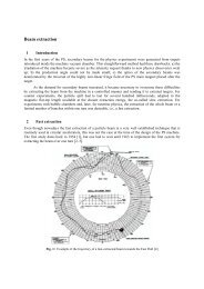
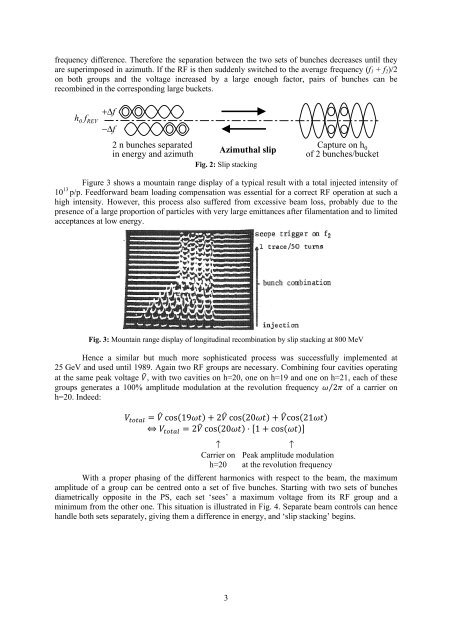
frequency difference. Therefore <strong>the</strong> separation between <strong>the</strong> two sets of bunches decreases until <strong>the</strong>yare superimposed <strong>in</strong> azimuth. If <strong>the</strong> <strong>RF</strong> is <strong>the</strong>n suddenly switched to <strong>the</strong> average frequency (f 1 + f 2 )/2on both groups and <strong>the</strong> voltage <strong>in</strong>creased by a large enough factor, pairs of bunches can berecomb<strong>in</strong>ed <strong>in</strong> <strong>the</strong> correspond<strong>in</strong>g large buckets.+Δfh 0 f REV−Δf2 n bunches separated<strong>in</strong> energy and azimuthAzimuthal slipFig. 2: Slip stack<strong>in</strong>gCapture on h 0of 2 bunches/bucketFigure 3 shows a mounta<strong>in</strong> range display of a typical result with a total <strong>in</strong>jected <strong>in</strong>tensity of10 13 p/p. Feedforward beam load<strong>in</strong>g compensation was essential for a correct <strong>RF</strong> operation at such ahigh <strong>in</strong>tensity. However, this process also suffered from excessive beam loss, probably due to <strong>the</strong>presence of a large proportion of particles with very large emittances after filamentation and to limitedacceptances at low energy.Fig. 3: Mounta<strong>in</strong> range display of longitud<strong>in</strong>al recomb<strong>in</strong>ation by slip stack<strong>in</strong>g at 800 MeVHence a similar but much more sophisticated process was successfully implemented at25 GeV and used until 1989. Aga<strong>in</strong> two <strong>RF</strong> groups are necessary. Comb<strong>in</strong><strong>in</strong>g four cavities operat<strong>in</strong>gat <strong>the</strong> same peak voltage , with two cavities on h=20, one on h=19 and one on h=21, each of <strong>the</strong>segroups generates a 100% amplitude modulation at <strong>the</strong> revolution frequency ⁄ 2 of a carrier onh=20. Indeed: cos19 2 cos20 cos21 2 cos20 1cos↑Carrier onh=20↑Peak amplitude modulationat <strong>the</strong> revolution frequencyWith a proper phas<strong>in</strong>g of <strong>the</strong> different harmonics with respect to <strong>the</strong> beam, <strong>the</strong> maximumamplitude of a group can be centred onto a set of five bunches. Start<strong>in</strong>g with two sets of bunchesdiametrically opposite <strong>in</strong> <strong>the</strong> <strong>PS</strong>, each set ‘sees’ a maximum voltage from its <strong>RF</strong> group and am<strong>in</strong>imum from <strong>the</strong> o<strong>the</strong>r one. This situation is illustrated <strong>in</strong> Fig. 4. Separate beam controls can hencehandle both sets separately, giv<strong>in</strong>g <strong>the</strong>m a difference <strong>in</strong> energy, and ‘slip stack<strong>in</strong>g’ beg<strong>in</strong>s.3