Roughness measuring systems from Hommel-Etamic ... - Teknikel
Roughness measuring systems from Hommel-Etamic ... - Teknikel
Roughness measuring systems from Hommel-Etamic ... - Teknikel

Create successful ePaper yourself
Turn your PDF publications into a flip-book with our unique Google optimized e-Paper software.
Surface texture parameters<br />
Surface texture parameters<br />
Surface texture parameters<br />
Evaluation<br />
Drawing entries<br />
Drawing entries<br />
Our service range<br />
Metrology<br />
Tactile metrology<br />
Pneumatic metrology<br />
Optical metrology<br />
Product range<br />
<strong>Roughness</strong> measurement<br />
Contour measurement<br />
Form measurement<br />
Optical shaft measurement<br />
Dimensional measurement<br />
Optical surface inspection<br />
Inspection process<br />
In-process<br />
Post-process<br />
PLC<br />
Final inspection<br />
Measuring room<br />
Service<br />
System solutions<br />
DKD calibration service<br />
Consulting, training and service<br />
www.hommel-etamic.com<br />
Our global presence.<br />
GRUPPE DREI ® 10/2008 · Art-Nr. 10037109<br />
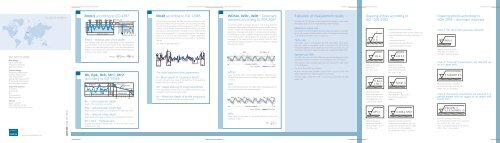
Rmr(c) according to ISO 4287<br />
Rmr(c) – material ratio of the profile<br />
Rmr indicates what ratio the totaled length in the material has<br />
assumed relative to the evaluation length (in %). The comparison<br />
is made in the specified section height c and the total evaluation<br />
length ln. The material ratio curve indicates the material ratio as a<br />
function of the section height.<br />
Rk, Rpk, Rvk, Mr1, Mr2<br />
according to ISO 13565<br />
Profile peak<br />
section<br />
Evaluation length In<br />
Profile valley section<br />
Core<br />
Reference line<br />
Reference section height c0<br />
Section height c1<br />
Material<br />
ratio curve<br />
Material ratio Rmr (c1)<br />
„Peak surface“<br />
Material ratio<br />
curve<br />
„Valley surface“<br />
Material ratio<br />
Rk – core roughness depth<br />
Depth of the roughness core profile.<br />
Rpk – reduced peak height Rpk<br />
Mean height of the peaks protruding <strong>from</strong> the roughness profile.<br />
Rvk – reduced valley depth<br />
Mean depth of the valleys reaching into the material <strong>from</strong> the core.<br />
Mr1, Mr2 – material ratio<br />
Smallest and greatest material ratio (in %) at the limits of the<br />
roughness core area.<br />
Motif according to ISO 12085<br />
The principle of the Motif standard consists of looking for local<br />
peaks and valleys in the primary profile, and associating one valley<br />
with the closest preceding and following peaks in order to create<br />
a Motif. Several iterative combinations of two Motifs each assure<br />
that the most important Motifs, the width of which fall below the<br />
limit A, are considered. If not otherwise specified, the default<br />
value is A = 0.5 mm (see measurement conditions page 4/5).<br />
The limit A has a similar function as the cut-off in the Gaußian<br />
filtering.<br />
The 16 % rule generally applies.<br />
H 1<br />
H 2<br />
H 3<br />
AR 1<br />
H j<br />
H j+1<br />
AR i<br />
H m-1<br />
H m<br />
The most important Motif parameters:<br />
R – Mean depth of roughness Motifs<br />
R is the arithmetic mean value of the depths Hj of the roughness<br />
Motifs within the evaluation length.<br />
AR – Mean spacing of roughness Motifs<br />
AR is the arithmetic mean value of the lengths ARi of the roughness<br />
Motifs within the evaluation length.<br />
Rx – Maximum depth of profile irregularity<br />
The deepest depth Hj within the evaluation length.<br />
WDSm, WDc, WDt – Dominant<br />
waviness according to VDA 2007<br />
The primary profile is checked for none, one or two dominant<br />
wavinesses. Narrow band filtering of the primary profile with the<br />
waviness creates the WD-profile that is used for calculating the<br />
parameters. The evaluation length ln is chosen either according to<br />
ISO 4288 (as for surface roughness measurements) or on the basis<br />
of the drawing entry. Period lengths are checked for dominant<br />
wavinesses in the range of 0.02 mm ≤ WDSm ≤ ln/5. To catch<br />
dominant wavinesses at WDSm > ln/5, it is necessary to enlarge<br />
the evaluation length.<br />
AR n<br />
Evaluation length ln<br />
P-profile WD-profile<br />
WDt<br />
WDSm<br />
WDSm<br />
Mean horizontal value of the profile elements, calculated <strong>from</strong><br />
the amplitude spectrum (mean periodic length of the dominant<br />
waviness).<br />
WDt<br />
Vertical difference between the highest and the deepest point of<br />
the WD-profile within the evaluation length.<br />
∆Z 1<br />
∆Z 2<br />
∆Z 3<br />
∆Z N-1<br />
∆Z N<br />
Evaluation length ln<br />
P-profile<br />
WD-profile<br />
WDc<br />
Mean value of the peaks of the profile elements within the<br />
evaluation length.<br />
Evaluation of measurement results<br />
According to ISO 4288 the surface measurement should be made where<br />
the highest values are to be expected (visual determination).<br />
Maximum value rule<br />
The surface is considered good when the measured values of a parameter<br />
do not exceed the fixed maximum value. In this case, the parameter<br />
is identified by the suffix „max“, e.g. Rz1max.<br />
16 % rule<br />
If the suffix „max“ is not specified, the 16% rule applies, which states<br />
that the surface is considered “good” if not more than 16% of the<br />
measured parameter values exceed the fixed maximum value. You will<br />
find further information about this rule in the standard ISO 4288:1997.<br />
Special rule VDA<br />
The 16% rule is not used. VDA 2006 assumes that the dispersion of the<br />
parameters is taken into account in the definition of the limit values.<br />
The maximum value rule applies generally even without the „max“ index<br />
in the designation.<br />
The use of the λs filter is prohibited.<br />
At Rz ≤ 2 µm the stylus tip radius is 2 µm, at Rz > 2 µm it is 5 µm. The<br />
distance between two <strong>measuring</strong> points is ≤ 0.5 µm.<br />
The cone angle is either 60° or 90°. If not otherwise specified, the cone<br />
angle is 90°.<br />
Drawing entries according to<br />
ISO 1302:2002<br />
e<br />
c<br />
a<br />
d b<br />
Rz 4<br />
Material removing<br />
machining;<br />
Rz = max. 4 µm<br />
U Ra 4<br />
L Ra 1<br />
Material removing<br />
machining; upper and<br />
lower limit value for Ra<br />
demanded; Ra = min.<br />
1 µm and max. 4 µm<br />
2/Pt 4<br />
Material removing<br />
machining; P-profile,<br />
traverse length = 2 mm;<br />
Pt = max. 4 µm<br />
Specifications for requirements<br />
a surface parameter with numeric value in µm<br />
b second requirement (surface parameter in<br />
µm)<br />
c production method<br />
d specification of valley direction<br />
e machining allowance in mm<br />
L Rz 2.5<br />
Material removing<br />
machining; lower limit<br />
value for Rz demanded;<br />
Rz = min. 2.5 µm<br />
Rzmax 4<br />
Material removing<br />
machining; Rz = max. 4 µm;<br />
the maximum value rule<br />
applies<br />
0.008-2.5/Rz1<br />
Material removing machining;<br />
transmission characteristic does not<br />
comply with standard case (cf. table)<br />
Rz = max. 1 µm; filter selection<br />
λs = 0.008 mm and λc = 2.5 mm<br />
Drawing entries according to<br />
VDA 2005 – dominant waviness<br />
Case 1: No dominant waviness allowed<br />
WDc 0<br />
Material removing machining;<br />
WDc 0 or WDt 0: no<br />
dominant waviness allowed<br />
Case 2: Dominant wavinesses are allowed up<br />
to an upper limit<br />
2.5x5/WDt 2.5<br />
Material removing machining;<br />
in the period range up to 2.5 mm,<br />
WDt = max. 2.5 µm applies<br />
Case 3: Dominant wavinesses are allowed in a<br />
period length with an upper or an upper and<br />
lower limit<br />
0.8x16/Rz 3<br />
0.2-2.5x5/WDc1.5<br />
Material removing machining;<br />
Rz: the evaluation length is 12.5 mm and<br />
λc = 0.8 mm, Rz = max. 3 µm;<br />
WDc: in the period range of 0.2 to 2.5 mm,<br />
WDc = max. 1.5 µm applies<br />
9 10 11 12 13 14