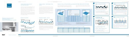
Roughness measuring systems from Hommel-Etamic ... - Teknikel
Roughness measuring systems from Hommel-Etamic ... - Teknikel
Roughness measuring systems from Hommel-Etamic ... - Teknikel

You also want an ePaper? Increase the reach of your titles
YUMPU automatically turns print PDFs into web optimized ePapers that Google loves.
Surface texture measurement Surface texture measurement<br />
Measurement conditions Measurement conditions<br />
Surface texture parameters<br />
Surface texture parameters<br />
Surface texture measurement<br />
with <strong>Hommel</strong>-<strong>Etamic</strong><br />
Surface texture is very important where it has a direct influence on the<br />
quality of the part. Therefore, it has to be defined as precisely as possible<br />
with the help of standardized surface texture parameters.<br />
This leaflet gives you an overview of the most important definitions,<br />
standards, and parameters of surface texture measurement.<br />
<strong>Hommel</strong>-<strong>Etamic</strong> manufactures a wide range of roughness <strong>measuring</strong><br />
<strong>systems</strong> providing a large variety of evaluation possibilities – in the<br />
<strong>measuring</strong> lab as well as on the production line.<br />
One particularly important aspect is the continuous monitoring of the<br />
roughness <strong>measuring</strong> <strong>systems</strong> for optimum accuracy. Our DKD calibration<br />
laboratory can calibrate your standards based on different surface<br />
texture parameters. For parameters not requiring accreditation, we offer<br />
an in-house calibration certificate.<br />
.<br />
Surface profiles – total height of the<br />
profile<br />
Surface profile is measured two-dimensionally using the tracing system.<br />
The unfiltered primary profile (P-profile) is the actual measured surface<br />
profile. Filtering it in accordance with ISO 11562 produces the waviness<br />
profile (W-profile) and the roughness profile (R-profile). The variable for<br />
determining the limit between waviness and roughness is the cut-off λc.<br />
Following ISO 4287, all parameter definitions are valid for both the<br />
roughness profile as well as for the primary and waviness profiles. The<br />
profile type is identified by the capital letters P, R or W.<br />
The total height Pt, Wt or Rt of the respective profile type is the maximum<br />
height between the highest peak and the deepest valley of the<br />
evaluation length profile.<br />
Selection of the cut-off (profile filter) according to ISO 4288:1998 and ISO 3274:1998<br />
The cut-off is selected depending on the work piece surface either according<br />
to the valley spacing, or the expected roughness values. At the<br />
same time the total evaluation length and the corresponding traverse<br />
length are defined according to standards. Deviations are necessary if<br />
the work piece does not allow the required traverse length. See drawing<br />
entries.<br />
Ra according to ISO 4287<br />
Center line<br />
RSm according to ISO 4287<br />
Center line<br />
.<br />
Periodic profiles<br />
e.g. turning, milling<br />
RSm<br />
Measuring conditions<br />
lr sampling length<br />
ln evaluation length<br />
lt traverse length<br />
λc cut-off<br />
λs shortwave profile filter<br />
r tip<br />
stylus tip radius<br />
ΔX digitization distance 1)<br />
1) The digitization distance is also<br />
standardized. This is set automatically<br />
by most roughness<br />
<strong>measuring</strong> instruments.<br />
Aperiodic profiles<br />
e.g. grinding, eroding<br />
Rz<br />
Ra – arithmetical mean deviation<br />
Ra is the arithmetic mean roughness value <strong>from</strong> the amounts of all<br />
profile values. Ra does not differentiate between peaks and valleys<br />
and has therefore a relatively weak information character.<br />
RSm – mean width of the profile elements<br />
RSm is the arithmetic mean value of the width of the roughness<br />
profile elements within the sampling length and requires the definition<br />
of height discriminations (c1, c2) matching the function of<br />
the surface.<br />
<strong>Roughness</strong> <strong>measuring</strong> <strong>systems</strong><br />
<strong>from</strong> <strong>Hommel</strong>-<strong>Etamic</strong> –<br />
Surface texture parameters in practice<br />
Division of a surface<br />
Unfiltered P-profile<br />
Evaluation lengths – cut-off<br />
Start-up length <strong>Roughness</strong> profile Run-off length<br />
RSm (mm)<br />
> 0.013 ...0.04<br />
> 0.04 ...0.13<br />
> 0.13 ...0.4<br />
> 0.4 ...1.3<br />
λc = lr (mm ln (mm) lt (mm) r tip<br />
(µm) λs (µm)<br />
0.08 0.4 0.48 2 2.5<br />
0.25 1.25 1.5 2 2.5<br />
0.8 4 4.8 2 or 5 * 2.5<br />
2.5 12.5 15 5 8<br />
Ra (µm)<br />
> (0.006) …0.02<br />
> 0.02 …0.1<br />
> 0.1 …2<br />
> 2 …10<br />
Rz (µm)<br />
> (0.025) …0.1<br />
> 0.1 …0.5<br />
> 0.5 …10<br />
> 10 …50<br />
Rz, Rz1max, Rt<br />
according to ISO 4287<br />
RPc according to EN 10049<br />
> 1.3 ...4<br />
8 40 48 10 25<br />
> 10 …80<br />
> 50 …200<br />
Center line<br />
Filtered W-profile<br />
Filtered R-profile<br />
The traverse length (lt) is the total length of the probe movement during<br />
the scanning process. It must be greater than the evaluation length in<br />
order to be able to form the roughness profile with the profile filter. With<br />
the exception of Rt and Rmr(c), the roughness parameters are defined<br />
within an evaluation length ln, which is determined using an average of<br />
five sampling lengths lr.<br />
The sampling length lr corresponds to the cut-off λc.<br />
Application example<br />
In a periodic profile the mean width of the profile elements RSm is used.<br />
With an RSm between 0.4 and 1.3 mm the following <strong>measuring</strong> conditions result:<br />
λc = 2.5 mm / ln = 12.5 mm / lt = 15 mm / r tip<br />
= 5 µm / λs = 8 µm.<br />
* At Rz ≤ 2 µm the stylus tip radius is 2 µm, at Rz > 2 µm it is 5 µm. The distance between two<br />
<strong>measuring</strong> points is ≤ 0.5 µm.<br />
Shortened standard evaluation length<br />
If the actual possible traverse length on the work piece surface is not enough for lt, the number<br />
of sampling lengths is reduced accordingly and specified in the drawing.<br />
If the actually available traverse length is less than a sampling length, the total height of profile<br />
Pt of the primary profile is evaluated instead of Rt or Rz.<br />
Measurement conditions for Motif parameters according to ISO 12085<br />
A* B* Traversing length Evaluation length λs Maximum stylus tip radius<br />
mm mm mm mm µm µm<br />
0.02 0.1 0.64 0.64 2.5 2 ± 0.5<br />
0.1 0.5 3.2 3.2 2.5 2 ± 0.5<br />
0.5 2.5 16 16 8 5 ± 1<br />
2.5 12.5 80 80 25 10 ± 2<br />
Rz – maximum height of profile<br />
Average value of the five Rz values.<br />
Rz1max – maximum height of profile<br />
Greatest Rz value <strong>from</strong> the five sampling lengths lr.<br />
Rt – total height of profile<br />
Rt is the distance between the highest peak and the deepest valley<br />
of the profile of the total evaluation length ln.<br />
RPc – standardized number of peaks<br />
RPc corresponds to the number of local peaks, which successively<br />
exceed an upper section line c1 and a lower section line c2. The<br />
number of peaks is related to a length of 10 mm irrespective of the<br />
evaluation length selected.<br />
* If not otherwise specified, the default values are A = 0.5 mm and B = 2.5 mm, respectively.<br />
DKD-K-02401<br />
Precision is our business.<br />
2<br />
3<br />
4<br />
5<br />
6 7
Surface texture parameters<br />
Surface texture parameters<br />
Surface texture parameters<br />
Evaluation<br />
Drawing entries<br />
Drawing entries<br />
Our service range<br />
Metrology<br />
Tactile metrology<br />
Pneumatic metrology<br />
Optical metrology<br />
Product range<br />
<strong>Roughness</strong> measurement<br />
Contour measurement<br />
Form measurement<br />
Optical shaft measurement<br />
Dimensional measurement<br />
Optical surface inspection<br />
Inspection process<br />
In-process<br />
Post-process<br />
PLC<br />
Final inspection<br />
Measuring room<br />
Service<br />
System solutions<br />
DKD calibration service<br />
Consulting, training and service<br />
www.hommel-etamic.com<br />
Our global presence.<br />
GRUPPE DREI ® 10/2008 · Art-Nr. 10037109<br />
Rmr(c) according to ISO 4287<br />
Rmr(c) – material ratio of the profile<br />
Rmr indicates what ratio the totaled length in the material has<br />
assumed relative to the evaluation length (in %). The comparison<br />
is made in the specified section height c and the total evaluation<br />
length ln. The material ratio curve indicates the material ratio as a<br />
function of the section height.<br />
Rk, Rpk, Rvk, Mr1, Mr2<br />
according to ISO 13565<br />
Profile peak<br />
section<br />
Evaluation length In<br />
Profile valley section<br />
Core<br />
Reference line<br />
Reference section height c0<br />
Section height c1<br />
Material<br />
ratio curve<br />
Material ratio Rmr (c1)<br />
„Peak surface“<br />
Material ratio<br />
curve<br />
„Valley surface“<br />
Material ratio<br />
Rk – core roughness depth<br />
Depth of the roughness core profile.<br />
Rpk – reduced peak height Rpk<br />
Mean height of the peaks protruding <strong>from</strong> the roughness profile.<br />
Rvk – reduced valley depth<br />
Mean depth of the valleys reaching into the material <strong>from</strong> the core.<br />
Mr1, Mr2 – material ratio<br />
Smallest and greatest material ratio (in %) at the limits of the<br />
roughness core area.<br />
Motif according to ISO 12085<br />
The principle of the Motif standard consists of looking for local<br />
peaks and valleys in the primary profile, and associating one valley<br />
with the closest preceding and following peaks in order to create<br />
a Motif. Several iterative combinations of two Motifs each assure<br />
that the most important Motifs, the width of which fall below the<br />
limit A, are considered. If not otherwise specified, the default<br />
value is A = 0.5 mm (see measurement conditions page 4/5).<br />
The limit A has a similar function as the cut-off in the Gaußian<br />
filtering.<br />
The 16 % rule generally applies.<br />
H 1<br />
H 2<br />
H 3<br />
AR 1<br />
H j<br />
H j+1<br />
AR i<br />
H m-1<br />
H m<br />
The most important Motif parameters:<br />
R – Mean depth of roughness Motifs<br />
R is the arithmetic mean value of the depths Hj of the roughness<br />
Motifs within the evaluation length.<br />
AR – Mean spacing of roughness Motifs<br />
AR is the arithmetic mean value of the lengths ARi of the roughness<br />
Motifs within the evaluation length.<br />
Rx – Maximum depth of profile irregularity<br />
The deepest depth Hj within the evaluation length.<br />
WDSm, WDc, WDt – Dominant<br />
waviness according to VDA 2007<br />
The primary profile is checked for none, one or two dominant<br />
wavinesses. Narrow band filtering of the primary profile with the<br />
waviness creates the WD-profile that is used for calculating the<br />
parameters. The evaluation length ln is chosen either according to<br />
ISO 4288 (as for surface roughness measurements) or on the basis<br />
of the drawing entry. Period lengths are checked for dominant<br />
wavinesses in the range of 0.02 mm ≤ WDSm ≤ ln/5. To catch<br />
dominant wavinesses at WDSm > ln/5, it is necessary to enlarge<br />
the evaluation length.<br />
AR n<br />
Evaluation length ln<br />
P-profile WD-profile<br />
WDt<br />
WDSm<br />
WDSm<br />
Mean horizontal value of the profile elements, calculated <strong>from</strong><br />
the amplitude spectrum (mean periodic length of the dominant<br />
waviness).<br />
WDt<br />
Vertical difference between the highest and the deepest point of<br />
the WD-profile within the evaluation length.<br />
∆Z 1<br />
∆Z 2<br />
∆Z 3<br />
∆Z N-1<br />
∆Z N<br />
Evaluation length ln<br />
P-profile<br />
WD-profile<br />
WDc<br />
Mean value of the peaks of the profile elements within the<br />
evaluation length.<br />
Evaluation of measurement results<br />
According to ISO 4288 the surface measurement should be made where<br />
the highest values are to be expected (visual determination).<br />
Maximum value rule<br />
The surface is considered good when the measured values of a parameter<br />
do not exceed the fixed maximum value. In this case, the parameter<br />
is identified by the suffix „max“, e.g. Rz1max.<br />
16 % rule<br />
If the suffix „max“ is not specified, the 16% rule applies, which states<br />
that the surface is considered “good” if not more than 16% of the<br />
measured parameter values exceed the fixed maximum value. You will<br />
find further information about this rule in the standard ISO 4288:1997.<br />
Special rule VDA<br />
The 16% rule is not used. VDA 2006 assumes that the dispersion of the<br />
parameters is taken into account in the definition of the limit values.<br />
The maximum value rule applies generally even without the „max“ index<br />
in the designation.<br />
The use of the λs filter is prohibited.<br />
At Rz ≤ 2 µm the stylus tip radius is 2 µm, at Rz > 2 µm it is 5 µm. The<br />
distance between two <strong>measuring</strong> points is ≤ 0.5 µm.<br />
The cone angle is either 60° or 90°. If not otherwise specified, the cone<br />
angle is 90°.<br />
Drawing entries according to<br />
ISO 1302:2002<br />
e<br />
c<br />
a<br />
d b<br />
Rz 4<br />
Material removing<br />
machining;<br />
Rz = max. 4 µm<br />
U Ra 4<br />
L Ra 1<br />
Material removing<br />
machining; upper and<br />
lower limit value for Ra<br />
demanded; Ra = min.<br />
1 µm and max. 4 µm<br />
2/Pt 4<br />
Material removing<br />
machining; P-profile,<br />
traverse length = 2 mm;<br />
Pt = max. 4 µm<br />
Specifications for requirements<br />
a surface parameter with numeric value in µm<br />
b second requirement (surface parameter in<br />
µm)<br />
c production method<br />
d specification of valley direction<br />
e machining allowance in mm<br />
L Rz 2.5<br />
Material removing<br />
machining; lower limit<br />
value for Rz demanded;<br />
Rz = min. 2.5 µm<br />
Rzmax 4<br />
Material removing<br />
machining; Rz = max. 4 µm;<br />
the maximum value rule<br />
applies<br />
0.008-2.5/Rz1<br />
Material removing machining;<br />
transmission characteristic does not<br />
comply with standard case (cf. table)<br />
Rz = max. 1 µm; filter selection<br />
λs = 0.008 mm and λc = 2.5 mm<br />
Drawing entries according to<br />
VDA 2005 – dominant waviness<br />
Case 1: No dominant waviness allowed<br />
WDc 0<br />
Material removing machining;<br />
WDc 0 or WDt 0: no<br />
dominant waviness allowed<br />
Case 2: Dominant wavinesses are allowed up<br />
to an upper limit<br />
2.5x5/WDt 2.5<br />
Material removing machining;<br />
in the period range up to 2.5 mm,<br />
WDt = max. 2.5 µm applies<br />
Case 3: Dominant wavinesses are allowed in a<br />
period length with an upper or an upper and<br />
lower limit<br />
0.8x16/Rz 3<br />
0.2-2.5x5/WDc1.5<br />
Material removing machining;<br />
Rz: the evaluation length is 12.5 mm and<br />
λc = 0.8 mm, Rz = max. 3 µm;<br />
WDc: in the period range of 0.2 to 2.5 mm,<br />
WDc = max. 1.5 µm applies<br />
9 10 11 12 13 14