Probing Systems For Co-ordinate Measuring machines - Teknikel
Probing Systems For Co-ordinate Measuring machines - Teknikel
Probing Systems For Co-ordinate Measuring machines - Teknikel
- No tags were found...

You also want an ePaper? Increase the reach of your titles
YUMPU automatically turns print PDFs into web optimized ePapers that Google loves.
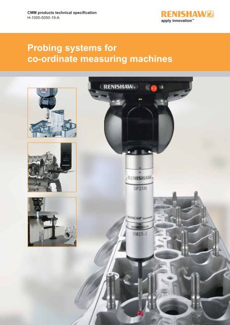
CMM products technical specificationH-1000-5050-19-A<strong>Probing</strong> systems forco-<strong>ordinate</strong> measuring <strong>machines</strong>
IntroductionRenishaw’s technologyRenishaw stands at the forefront ofautomated metrology, with the Group’sproducts providing manufacturers withthe ability to machine componentsaccurately, and perform measurementtraceable to international standards.Probe technology, allows fast, highlyrepeatable measurements to be carriedout on co-<strong>ordinate</strong> measuring <strong>machines</strong>(CMMs).A wide range of automated probingsystems has been developed to meetthe needs of post-process inspection,for quality control.During the manufacturing operation,probes used on computer numericallycontrolled (CNC) machine toolsprovide the measurement capabilityto automatically control the machiningprocess. This eliminates the needfor costly, time consuming manualprocedures.Renishaw gives extra capability to CNCmachine tools and CMMs by enablingscanning and digitising of 3-dimensional(3D) forms to generate the necessaryNC programs to produce either replicaparts, or moulds and dies.Renishaw has developed the Cyclonescanning machine and associatedsoftware, a cost-effective solution tostand-alone digitising.The revolutionary manufacturingsystem, RAMTIC (Renishaw’sautomated milling, turning andinspection centre), maximises thepotential of existing machine tools,enabling milling, turning and inspectionon a single machine, together withautomated loading and unloading ofmaterials and tools.CNC machine tools and CMMs benefi tfrom regular volumetric checking byRenishaw’s automated ball-bar andmachine checking gauge.<strong>Co</strong>mprehensive machine calibrationcan be undertaken, when necessary,using Renishaw’s innovative lasercalibration systems.Renishaw has developed linear scale,laser interferometer and encodersystems for fi tting to a variety of<strong>machines</strong>, to provide axis displacementmeasurement. Dedicated lengths ofrigid scale are not required, sinceRenishaw’s approach has been toproduce fl exible scale that can bedispensed from a reel and cut to therequired length.Renishaw has also applied itsinnovatory approach to produce aRaman microscope and accessories for2D spectral analysis of materials in anon-destructive manner.From its leading market position, theRenishaw Group continues to expandits product range into ever increasingbusiness sectors worldwide. Identifyingand targeting new market opportunitieshas led to the continuous developmentand introduction of new, highlyinnovative products which signifi cantlyenhance the manufacturing capabilitiesin a wide range of industries.
<strong>Probing</strong> systems forco-<strong>ordinate</strong> measuring <strong>machines</strong>Introduction to CMM probingCMMs are used for a wide variety of industry applications,especially for post-process inspection of manufacturedcomponents. Renishaw’s probes and probing systems havebecome the industry choice for rapid and accurate inspection.CMMs, which act as a quality reference, use probingsystems to replace traditional manually operated measuringinstruments such as micrometers, vernier callipers anddedicated gauges.Probe systemsRenishaw’s probe systems are available in a wide variety oftypes to enable a best match for a particular application.Fitting the probe on the CMMThe probe is mounted on the CMM via a probe head. Thetype of head is determined by the fl exibility and automationrequired. Renishaw has designed a range of probe heads formanual and automated systems.Motorised heads maximise probing effi ciency and give a 3-axisCMM, 5-axis capability. A motorised head can also be usedwith Renishaw’s autochange systems which allows rapid andautomatic exchange of multiple probe types and extensioncombinations.Advanced controlTraditionally, scanning has been limited to relatively slow<strong>machines</strong> but Renishaw’s universal CMM controller familyenables this function at speeds many times faster than waspreviously possible.AccessoriesThe range of accessories enhances the basic system byoffering additional capability such as stylus changing for theprobe, probe sensor changing for multiple probe requirementsand extension bars to provide access to deep features.Renishaw supplies a comprehensive range of styli forcomponent inspection and scanning applications which areavailable in a variety of profi les, sizes and fittings to bestsuit the probe employed and the components’ features anddimensions.To avoid the risk of compromising measurement performance,always use a replacement stylus from Renishaw!<strong>Co</strong>ntents1 How to use this guide2 Touch-trigger probeswithout stylus module changing3 Touch-trigger probeswith stylus module changing4 Scanning probes5 Manual probe headswith integral M8/autojoint probe mount6 Manual probe headswith integral TP20 stylus module mount7 Motorised probe headsservo type8 Motorised probe headsindexing type9 Interfaces and controllers10 Change/storage racksfor autojointed probes/extensions11 Extension bars12 Shanks13 Accessories14 Styli and custom design service15 Glossary of terms16 Product index
<strong>Probing</strong> systems forco-<strong>ordinate</strong> measuring <strong>machines</strong>How to use this guideHow to use this guide1-1This TECHNICAL SPECIFICATIONS document is intendedto help you select the most appropriate probing system foryour CMM. The probing system includes the probe withstylus, the method of attachment of the probe to the CMMby use of a probe head or simple shank, and the necessaryprobe/head controlling interfaces.Probe system selectionBefore selecting the most appropriate probe system, youshould clearly understand the scope of measurementapplications to be addressed on your CMM. Renishaw’sproduct range covers all types of probing requirements,from simple touch-trigger point measurement through toadvanced part profi le scanning. Where a standard productproves not to be ideal, Renishaw’s custom design service isavailable to accommodate you requirements.This technical specifi cations document is divided intosections that focus on the different parts of the probingsystem and indicates the particular benefi ts of each product.The technical information for each product is also given sothat performance data can be compared where more thanone product appears suitable.Step-by-step selection procedureStep 1 (see sections 5, 6, 7 and 8)<strong>Systems</strong> suitable for your CMMQ? Which type of CMM do you have or wish to purchase?Manual CMM - go to sections 5/6 to see the family trees ofprobing systems that are suited to manual CMMs. Identifythe probe(s) and probe head(s) that are of interest, andthen proceed to steps 2 and 3 to fi nd out more informationon these products and fi nalise your selection.DCC CMM - go to sections 7/8 to see the family trees ofprobing systems that are suited to DCC CMMs. Identify theprobe(s) and probe head(s) that are of interest, and thenproceed to steps 2 and 3 to fi nd out more information onthese products and fi nalise your selection.NOTE: All probes shown in this document are suitable foruse on DCC CMMs.Step 2 (see sections 2/3/4)Probe selectionDetailed information on each probe is given in one of threesections as described below.<strong>Co</strong>ntact trigger probes (see sections 2 and 3)Discrete point, contact trigger probes (also calledtouch-trigger probes) are ideal for inspection of 3dimensional prismatic parts and known geometries. Theseprobes are highly versatile and are suitable for a diverserange of applications, materials and surfaces, and thereis a wide range of accessories available for them. Theprobes are segregated into two sections here - probeswithout, and probes with stylus module changing.Stylus module changing is a very important considerationas it enables higher productivity and the ability to alwaysselect the best measurement solution for the application.A further distinction between contact trigger probes istheir type of design. There are kinematic probes andelectronic probes to choose from. Probe sizes varydue to the features of the probe. The larger kinematicprobes are extremely robust and are very well suited tomanual CMMs due to their large overtravel capability. Thesmaller probes are suited to applications where there is aneed to access restricted spaces. Renishaw’s electronicprobes offer extended life suitable for high density pointprofi le measurement and also permit higher accuracythan kinematic probes. Depending on the type of CMMand the level of utility required, there is a choice betweenshank mounted, M8 thread or autojoint mounted probes.Renishaw’s autojoint mounted probes and extensionscan be rapidly interchanged for increased fl exibility andproductivity.<strong>Co</strong>ntact scanning probes (see section 4)Scanning is ideal for the inspection of geometric formsand full profi le measurement where thousands of datapoints can describe the form more fully than a few discretepoints. A large amount of information can be collected ina very short time giving better direct results. Renishaw’srange of fi xed and indexable type scanning probes offershigh accuracy, excellent robustness and low contact forcescanning. All Renishaw scanning probes feature rapidinterchange between stylus confi gurations to furtherincrease fl exibility and productivity.
Step 3 (see sections 5/6/7/8)Probe head selectionHaving selected the probe type, refer again to the familytrees (sections 5 and 6 for manual CMMs or sections 7 and8 for DCC CMMs) to see which probe head(s) are suitable.Manual CMMs - are usually fi tted with shank-mountedprobes or manual probe heads. Renishaw offer varieties ofmanual probe heads which are segregated into sections5/6 here detailing manual probe heads with integral M8/autojoint or with integral TP20 stylus module mount.A further design consideration is the choice of fixed orarticulating/indexing manual head types. The type ofprobe head required can be determined by examiningthe features of each head and matching them to yourrequirements.DCC CMMs - can be fi tted with either manual or motorisedprobe head systems, so the choice must be made havingconsidered the applications of the CMM. Motorised headsare segregated into sections 7/8 here detailing servo typeand indexing type motorised heads. Fitting the probeon a CMM using a motorised head is the easiest way tovastly improve the capability of the CMM and maximiseproductivity. The indexing type motorised heads aredesigned to position the probe at one of 720 positions,in 7.5° steps, so probing can be carried out at manyangles. The repeatability of the head means that thesepositions can be recalled at any time without the need forre-qualifi cation. This can save a great deal of time for theoperator, and encourages system optimisation by applyingthe probe to the surface at the best angle for the mostaccurate result. Servo type motorised heads provide almostunlimited angular positioning and are ideally suited tohorizontal arm CMMs.Step 4 (see section 9)Probe / probe head, interface selectionThe probe data in sections 2, 3 and 4 defi nes the electricalinterface(s) compatible with the chosen probe. See section9 for full details of probe interfaces.The probe head data in sections 5, 6, 7 and 8 defi nesthe type of controller required to integrate the probe headinto the CMM. See section 9 for full details of probe headinterfaces.Step 5 (see sections 11 and 12)Extension bar / shank selection<strong>For</strong> probes and probe heads that are shank mounted on theCMM, go to section 12 to choose the appropriate shank.Section 11 details a comprehensive range of extension barsto enhance the versatility of your probe system. Rememberthat Renishaw offers a custom design service if the typeof shank/extension you require is not a standard product.Step 6 (see sections 2, 3, 4 and 10)Changer system selectionMany of Renishaw’s probes, when fi tted to DCC CMMs,are capable of rapid automatic interchange betweenstylus configurations or even between different typesof probe. Refer to sections 2, 3 and 4 to see if your chosenprobe has change rack compatibility, and for details of thesehighly productive systems. Renishaw’s autochange racksystems allow rapid exchange between probe sensorsand extensions with the Renishaw autojoint and aredetailed in section 10.Step 7 (see section 13)AccessoriesCheck the accessories section 13, for other accessoriesavailable for your chosen probe system.Step 8 (see section 14)Stylus selectionRenishaw produces a wide range of styli designed tooptimise measurement performance. A brief overview isgiven in section 14. Please also see Renishaw’s Styliand accessories guide (part number H-1000-3200) forcomprehensive details.NOTE: Section 15 contains a glossary of terms used in thisdocument.This document contains information on Renishaw’s currentCMM products range. If you require additional informationon these and discontinued products, please visit ourwebsite: www.renishaw.comHow to use this guide1-2
<strong>Probing</strong> systems forco-<strong>ordinate</strong> measuring <strong>machines</strong>TP7M / TP7M EP probesThe TP7M range comprises electronic probes usingTouch-trigger probeswithout stylus module changing2-1strain gauge technology which gives higher accuracythan kinematic touch-trigger probes. Incorporating amultiwired autojoint connection, the TP7M is compatiblewith the PH10M/PH10MQ motorised heads, PH6M fixedprobe head, and the range of PEM extension bars.The autojoint also allows fast probe changing, eithermanually or automatically, with a Renishaw autochangerack system.The enhanced performance TP7M EP is capableof achieving a 3D accuracy of
TP2-5W probesM8 × 1.25 threadThe TP2-5W is one of Renishaw’s best known products. It is a 13 mm (0.51 in)diameter standard kinematic touch-trigger probe with an M8 thread mount. Itsadjustable stylus force enables the probe to support a wide range of styli.The TP2 is small, light and compatible with a wide range of accessories, andis suitable for manual and DCC CMMs.Ø13 mmTP2-5W features and benefits:(0.52 in)• Small, light, versatile probe• Adjustable trigger force3 mm• <strong>Co</strong>mpatible with M2 styli(0.12 in)• <strong>Co</strong>mpatible with the full range of Renishaw probeheads and accessoriesM2 × 0.4 thread9 mm (0.35 in)38 mm (1.5 in)Touch-trigger probeswithout stylus module changing2-2• Suitable for manual and DCC CMMsMaximumXY overtravel14° 14°TP1 (S) probeThis large, robust kinematic probe has a high degree of overtravel and isshank mounted, making it ideal for use on manual CMMs. The probe signal iscarried to the CMM via an external cable and the probe has adjustable stylusforce to help optimise its performance.+Z overtravel4.0 mm (0.16 in)TP1(S) features and benefits:• Ideal for manual CMMs• RobustØ46 mm(1.8 in)15 mm (0.59 in)46 mm (1.8 in)• Large overtravel rangeM3 × 0.5 thread• Large adjustable trigger force range• Shank mountedMaximumXY overtravel19.5° 19.5°+Z overtravel8.5 mm (0.34 in)Specification summary TP2-5W TP1(S)PRINCIPAL APPLICATION Universal DCC and manual CMMs. Manual CMMs.SENSE DIRECTIONS 5-axis: ±X, ±Y, +Z 5-axis: ±X, ±Y, +ZUNIDIRECTIONAL REPEATABILITY MAXIMUM(2σ µm) (at stylus tip)0.35 µm (0.000014 in) 0.50 µm (0.00002 in)PRE-TRAVEL VARIATION 360° (XY PLANE) ±0.80 µm (0.000032 in) ±2 µm (0.00008 in)WEIGHT *excluding shank and cable 22 g (0.78 oz) 128 g* (4.52 oz*)STYLUS RANGE M2 M3STYLUS FORCE RANGE (ADJUSTABLE) 0.07 N - 0.15 N 0.1 N - 0.5 NSTYLUS FORCE (SET BY RENISHAW) 0.07 N - 0.08 N 0.15 NSTYLUS OVERTRAVEL (TYPICAL)XY PLANE±14°±19.5°+Z axis4 mm (0.16 in) @ 0.07 N3 mm (0.12 in) @ 0.15 N8.5 mm (0.34 in) @ 0.1 N5 mm (0.20 in) @ 0.5 NMAXIMUM EXTENSION ON PH10 SERIES 300 mm (11.81 in) N/AMOUNTING METHOD M8 thread Shank to suit machineSUITABLE INTERFACE PI 4-2, PI 7-2, PI 200, UCC PI 4-2, PI 7-2, PI 200, UCCAbove data applies to test conditions as follows: Stylus length 10 mm (0.39 in) [re TP2-5W] or 31 mm (1.22 in) [re TP1(S)].Stylus velocity 480 mm/min (1.57 ft/min). Stylus force 0.07-0.08 N [re TP2-5W] or 0.15 N [re TP1(S)].
<strong>Probing</strong> systems forco-<strong>ordinate</strong> measuring <strong>machines</strong>TP6 / TP6A probesM8 × 1.25 threadThe TP6 is an M8 thread mounted probe whilethe TP6A has an autojoint, which means that itTouch-trigger probeswithout stylus module changing2-3can be changed quickly and easily without theneed to re-qualify stylus tips. The probe designis robust with large overtravel and adjustabletrigger force.TP6 / TP6A features and benefits:• Autojoint or M8 version• Long stylus carrying capabilityØ25 mm(0.98 in)6.5 mm(0.26 in)M3 × 0.5 thread22° 22°MaximumXY overtravel15 mm (0.59 in)41 mm (1.61 in)+Z overtravel5.5 mm (0.22 in)• Large stylus overtravel• Robust• Adjustable trigger force range• M3 stylus mountØ25 mm(0.98 in)6.5 mm(0.26 in)15 mm (0.59 in)46.5 mm (1.83 in)49 mm (1.93 in)22° 22°+Z overtravel5.5 mm (0.22 in)MaximumXY overtravelSpecification summary TP6 TP6APRINCIPAL APPLICATIONRobust universal DCC andmanual CMMs.As TP6 but with fastprobe exchange withoutrequalifi cation.SENSE DIRECTIONS 5-axis: ±X, ±Y, +Z 5-axis: ±X, ±Y, +ZUNIDIRECTIONAL REPEATABILITY MAXIMUM(2σ µm) (at stylus tip)0.35 µm (0.000014 in) 0.35 µm (0.000014 in)PRE-TRAVEL VARIATION 360° (XY PLANE) ±1 µm (±0.00004 in) ±1 µm (±0.00004 in)WEIGHT 56 g (1.98 oz) 76 g (2.68 oz)STYLUS RANGE M3 M3STYLUS FORCE RANGE (ADJUSTABLE) 0.11 N - 0.3 N 0.11 N - 0.3 NSTYLUS FORCE (SET BY RENISHAW) 0.11 N - 0.13 N 0.11 N - 0.13 NSTYLUS OVERTRAVEL (TYPICAL)XY plane±22°±22°+Z axis5.5 mm (0.22 in) @ 0.11 N5.5 mm (0.22 in) @ 0.11 N2 mm (0.08 in) @ 0.3 N2 mm (0.08 in) @ 0.3MAXIMUM EXTENSION ON PH10 SERIES 200 mm (7.87 in) 200 mm (7.87 in)MOUNTING METHOD M8 thread AutojointSUITABLE INTERFACE PI 4-2, PI 7-2, PI 200, UCC PI 4-2, PI 7-2, PI 200, UCCAbove data applies to test conditions as follows: Stylus length 21 mm (0.83 in).Stylus velocity 480 mm/min (1.57 ft/min). Stylus force 0.11-0.13 N
TP200 / TP200B modular probesThe TP200/TP200B are electronic probes using straingauge technology, which gives higher accuracy thankinematic touch-trigger probes. They combine outstandingmetrology performance with superior functionality toproduce a highly versatile DCC CMM probing system withexcellent productivity.The TP200 system components are:• TP200 probe body – the standard model• TP200B probe body – a variant model with increasedvibration tolerance• TP200 stylus module – choice of fi xed overtravel forces:‘SF’ (standard force) or ‘LF’ (low force)There is also the ‘EO’ (extended overtravel) module,which has the same overtravel force as the ‘SF’ butprovides increased operating range and protection inthe probe Z axisTouch-trigger probeswith stylus module changing3-1• PI 200 probe interface• SCR200 stylus changing rackTP200 probe bodyThe TP200 probe incorporates micro strain gaugetransducers, delivering excellent repeatability and accurate3D form measurement even with long styli. The sensortechnology gives sub-micron triggering performance andeliminates the lobing characteristics encountered withstandard probes. The solid-state ASIC electronics withinthe probe ensure reliable operation over millions of triggerpoints.TP200B probe bodyThe TP200B probe uses the same technology as TP200but has been designed to have a higher tolerance tovibration. This helps to overcome the problem of ‘air’ triggergeneration which can arise from vibrations transmittedthrough the CMM or when using longer styli with fasterpositioning speeds.TP200probebodyNOTE: We do not recommend the use of TP200B with theLF module or cranked/star styli.TP200stylusmodule
<strong>Probing</strong> systems forco-<strong>ordinate</strong> measuring <strong>machines</strong>TP200 stylus moduleM8 × 1.25 threadThe stylus module is mounted on the probeTouch-trigger probeswith stylus module changing3-2via a highly repeatable magnetic kinematicjoint, providing a rapid stylus changingcapability and probe overtravel protection.There are three modules available, with twodifferent overtravel forces:• The SF (standard force) module issuitable for most applications.• The LF (low force) module isrecommended for use with small precisionball styli or on delicate materials.• The EO (extended overtravel) moduleis recommended for use whenincreasing the speed of the CMMmay lead to stopping distances whichexceed the overtravel range providedin the SF/LF modules. The EO modulehas an additional 8 mm (0.32 in) ofovertravel in the probe Z axis to protectagainst damage to the sensor in suchcircumstances. Overtravel force is thesame as the SF module.Status LEDsØ13.5 mm(0.53 in)4 mm(0.16 in)M2 × 0.4 thread14° 14°MaximumXY overtravelKinematicplane5 mm(0.20 in)30 mm(1.18 in)SF/LF 13 mm (0.51 in)EO 24 mm (0.95 in)module notshownSF/LF 4.5 mm (0.18 in)EO 12.5 mm (0.49 in)+Z overtravel4 mm (0.16 in)-Z overtravel by separation ofthe module from the sensorPI 200 probe interfaceThe PI 200 is a unit capable of the automaticrecognition and interfacing of TP200/B and alsoconventional touch-trigger probes (TP2, TP6,TP20). Two switchable levels of probe triggersensitivity are provided to accommodate differingapplications. The PI 200 interface is covered fullyin section 9.PI 200SCR200 stylus changing rackThe SCR200 provides rapid, automatic changingof stylus modules without the need to re-qualifystylus tips. The SCR200 is powered entirely bythe PI 200 and provides features to facilitate safestylus changing.245 mm (9.65 in)MSR1 module storage rack<strong>For</strong> manual storage of modules - see section 13.Probe maintenanceCK200 (Renishaw part number A-1085-0016) isa specialised cleaning material supplied for theremoval of contamination from the location facesof the magnetically retained kinematic couplingsof the TP20, TP200 and SP25M probe systems.The frequency of cleaning should be determinedaccording to the conditions of use.190 mm (7.84 in)SCR200
TP200 / TP200B features and benefits:• Excellent repeatability and precision 3D formmeasurement• Rapid exchange between stylus confi gurationswithout the need to re-calibrate• 6-way measuring capability (±X, ±Y, ±Z)• SF and LF modules to give overtravel force to suitthe application• EO module to give increased overtravel in probeZ axis• Zero reseat errors and no lobing effect• Suitable for intensive ‘peck’ or ‘stitch’ scanning• Stylus reach up to 100 mm (3.99 in) GF rangeTouch-trigger probeswith stylus module changing3-3• Module life of >10 million triggers• <strong>Co</strong>mpact size• <strong>Co</strong>mpatible with the full range of Renishaw probeheads and accessoriesSpecification summary TP200 TP200BPRINCIPAL APPLICATIONDCC CMM where high accuracyis required.As TP200 but where ‘air’* triggerevents occur.SENSE DIRECTIONS 6-axis: ±X, ±Y, ±Z 6-axis: ±X, ±Y, ±ZUNIDIRECTIONAL REPEATABILITY(2σ µm)Trigger level 1Trigger level 20.40 µm (0.000016 in)0.50 µm (0.00002 in)0.40 µm (0.000016 in)0.50 µm (0.00002 in)XY (2D) FORM MEASUREMENTDEVIATIONTrigger level 1Trigger level 2±0.80 µm (0.000032 in)±0.90 µm (0.000036 in)±1 µm (0.00004 in)±1.2 µm (0.000047 in)XYZ (3D) FORM MEASUREMENTDEVIATIONTrigger level 1Trigger level 2±1 µm (0.00004 in)±1.40 µm (0.000056 in)±2.50 µm (0.0001 in)±4 µm (0.00016 in)REPEATABILITY OF STYLUSCHANGEWith SCR200Manual±0.50 µm (0.00002 in) max.±1 µm (0.00004 in) max.±0.50 µm (0.00002 in) max.±1 µm (0.00004 in) max.TRIGGER FORCE(at stylus tip)XY planeZ axisAll modulesAll modules0.02 N0.07 N0.02 N0.07 NOVERTRAVELFORCE(@ 0.50 mmdisplacement)XY planeZ axisSF/EO moduleLF moduleSF/EO moduleLF module0.2 N to 0.4 N0.1 N to 0.15 N4.90 N1.60 N0.2 N to 0.4 N0.1 N to 0.15 N4.90 N1.60 NWEIGHT (probe sensor and module) 22 g (0.78 oz) 22 g (0.78 oz)MAXIMUM EXTENSION (if on a PH10 series head) 300 mm (11.81 in) 300 mm (11.81 in)MAXIMUM RECOMMENDEDSTYLUS LENGTH(M2 styli range)SF/EO moduleLF module50 mm (1.97 in) steel to100 mm (3.94 in) GF20 mm (0.79 in) steel to50 mm (1.97 in) GF50 mm (1.97 in) steel to100 mm (3.94 in) GF20 mm (0.79 in) steel to50 mm (1.97 in) GFMOUNTING METHOD M8 thread M8 threadSUITABLE INTERFACE PI 200, UCC PI 200, UCCSTYLUS MODULE CHANGINGRACKAutomaticManualSCR200MSR1SCR200MSR1Above data applies for test conditions as follows: Stylus length 50 mm (1.97 in) Stylus velocity 480 mm/min (1.57 ft/min).* Air trigger (or false trigger). The TP200B reduces probe triggers that may be caused by vibrations.
<strong>Probing</strong> systems forco-<strong>ordinate</strong> measuring <strong>machines</strong>TP20 / TP20 NI modular probesThe TP20 is a 5-way or 6-way kinematic touch-Touch-trigger probeswith stylus module changing3-4trigger probe. Its two piece design comprises aprobe body and detachable stylus module(s),which gives the ability to change stylusconfi gurations either manually or automaticallywithout re-qualifi cation of the stylus tips, providingsignifi cant time savings in inspection routines.A direct replacement for the industry standardRenishaw TP2 probe, the TP20 probe systembrings a range of new benefi ts to manual andDCC CMM applications, and can easily beretrofi tted to existing TP2 installations.The TP20 can be used on a wide range ofRenishaw’s manual or motorised probe heads,either by direct mounting using the standard M8thread or, alternatively, by using a PAA# adaptorto connect to an autojoint.TP20 probebodyTP20stylus module(7 variants)The system components are:• TP20/TP20 NI probe body• TP20 stylus module – seven module variantsallow for optimisation of performance to suitthe application• MCR20 module changing rack – automaticoperation• The TP20 probe system may be used withRenishaw’s PI 4-2, PI 7-2 or PI 200 probeinterfaces (see section 9)M8 × 1.25 threadTP20 probe bodyThe TP20 probe body houses one half of thehighly repeatable magnetic kinematic couplingthat attaches the stylus module and body. Thebody also contains a magnetic proximity switchto inhibit triggering of the probe during automaticmodule changing with MCR20.NOTE: If the probe is operated close tomagnetised parts/clamping etc, the probetrigger may become inhibited. <strong>Co</strong>untermeasuresinclude the use of long styli, stylus extensions orbody orientation to increase the distance to themagnetic source. Alternatively, use the TP20 NIprobe body.Ø13.2 mm(0.52 in)3 mm(0.12 in)M2 × 0.4 thread14° 14°9 mm (0.35 in)SF/LF/MF/EF 38 mm (1.50 in)6W 42 mm (1.65 in)EM1 88 mm (3.46 in)EM2 113 mm (4.45 in)+Z overtravelTP20 NI probe bodyThe TP20 NI probe differs from the TP20 body inthat it is not affected by magnetic fi elds. Howeverthe probe trigger must be inhibited throughsoftware during change cycles using the MCR20.MaximumXY overtravel+Z overtravelSF/EM1/EM2 4 mm (0.16 in)LF3.1 mm (0.12 in)MF3.7 mm (0.15 in)EF2.4 mm (0.09 in)6W4.5 mm (0.18 in)-Z overtravel-Z overtravel6W 1.5 mm (0.06 in)
TP20 stylus moduleThe TP20 stylus module houses the kinematicswitching touch sensor mechanism, carriesthe stylus assembly and provides overtravelin ±X, ±Y and +Z axes (or ±Z in the case ofTP20 6-way module). The stylus mountingthread accepts styli from the Renishaw M2range.A range of seven, application specifi c, stylusmodules is available, being identifi ed bycoloured caps:• SF - Standard force stylus module(black cap)• LF - Low force stylus module(green cap)10 mm (0.39 in)30 mm (1.18 in)50 mm (1.97 in)60 mm (2.36 in)LFSFMFEF6WEM1EM2Touch-trigger probeswith stylus module changing3-5• MF - Medium force stylus module(grey cap)100 mm (3.94 in)• EF - Extended force stylus module(brown cap)125 mm (4.92 in)• 6W - 6-way stylus module(blue cap)Stylus comparison• EM1 SF - Standard force extensionmodule• EM2 SF - Standard force extensionmoduleMCR20 module changingrackThe MCR20 probe module changing rack isdesigned to securely store stylus modulesready for rapid automatic changing, whilstprotecting mating surfaces from any airbornecontaminants within the working environment.MSR1 module storage rack<strong>For</strong> manual storage of modules - seesection 13.145 mm (5.71 in)200 mm (7.87 in)15 mm(0.59 in)60 mm(2.36 in)MCR20Probe maintenanceCK200 (Renishaw part number A-1085-0016)is a specialised cleaning material suppliedfor the removal of contamination from thelocation faces of the magnetically retainedkinematic couplings of the TP20, TP200 andSP25M probe systems. The frequency ofcleaning should be determined according tothe conditions of use.Ø55 mm(2.17 in)
<strong>Probing</strong> systems forco-<strong>ordinate</strong> measuring <strong>machines</strong>TP20 / TP20 NI features andbenefits:Touch-trigger probeswith stylus module changing3-6• A kinematic touch-trigger probe systemfor manual and DCC CMMs• Rapid exchange between stylusconfi gurations without the need tore-calibrate• A choice of seven stylus modules,giving 5-axis or 6-axis operation,allow optimisation of probe and stylusperformance to the given application• Easily retrofi tted to all Renishawstandard probe heads (M8 or autojointfi tting) and compatible with existing TTPinterfaces• Metrology performance equivalent toindustry proven TP2-5W probe• <strong>Co</strong>mpatible with the full range ofRenishaw probe heads and accessoriesSpecification summary (1) TP20 TP20 NIPRINCIPAL APPLICATIONSENSE DIRECTIONSPRE-TRAVEL VARIATIONUNIDIRECTIONALREPEATABILITY (2σ µm)(at stylus tip)All modules except 6W6WLFSF/EM1/EM2MFEF6WSF/LF/EM1/EM2MFEF6WDCC and manual CMMs suitablefor most applications.5-axis: ±X, ±Y, +Z6-axis: ±X, ±Y, ±Z±0.60 µm (±0.000023 in)±0.80 µm (±0.000032 in)±1 µm (±0.000039 in)±2 µm (±0.000079 in)±1.50 µm (±0.000058 in)±0.35 µm (±0.000014 in)±0.50 µm (±0.000020 in)±0.65 µm (±0.000026 in)±0.80 µm (±0.000032 in)DCC and manual CMMs whereoperation is within a magneticfi eld.5-axis: ±X, ±Y, +Z6-axis: ±X, ±Y, ±Z±0.60 µm (±0.000023 in)±0.80 µm (±0.000032 in)±1 µm (±0.000039 in)±2 µm (±0.000079 in)±1.50 µm (±0.000058 in)±0.35 µm (±0.000014 in)±0.50 µm (±0.000020 in)±0.65 µm (±0.000026 in)±0.80 µm (±0.000032 in)±0.50 µm (±0.000020 in)±1 µm (±0.000040 in)REPEATABILITY OF STYLUSCHANGE (maximum)With MCR20Manual±0.50 µm (±0.000020 in)±1 µm (±0.000040 in)STYLUS RANGE M2 M2MOUNTING METHOD M8 thread M8 threadSUITABLE INTERFACE PI 4-2, PI 7-2, PI 200, UCC PI 4-2, PI 7-2, PI 200, UCCSTYLUS MODULEAutomatic MCR20MCR20CHANGING RACKManual MSR1MSR1Above data applies for test conditions as follows: Stylus length 10 mm (0.39 in). Stylus velocity 480 mm/min (1.57 ft/min)
Specification summary (2)Module Application guide Maximum extensionon PH10 series headLFSFEM1EM2MFEF6WThe low force stylus module, identifi ed by a green cap,is suited to applications that require low trigger force,e.g. rubber seals.The standard force stylus modules, identifi ed by blackcaps, are suited to the majority of applications.The medium force stylus module, identifi ed by a grey cap,is for use where a higher trigger force than standard isrequired.The extended force stylus module is identifi ed by a browncap. Typically, this stylus module will only be required withlarge stylus assemblies, and where spurious ‘air’ triggerscaused by machine vibration and acceleration, precludethe use of either SF, LF or MF modules.The 6-way stylus module, identifi ed by a blue cap, hasbeen designed for applications requiring measurement inthe –Z direction, for example when measuring the widthof undercuts.Weight(body and module)300 mm (11.81 in) 22 g (0.78 oz)300 mm (11.81 in)300 mm (11.81 in)*300 mm (11.81 in)*22 g (0.78 oz)28 g (0.99 oz)30 g (1.06 oz)300 mm (11.81 in) 22 g (0.78 oz)300 mm (11.81 in) 22 g (0.78 oz)300 mm (11.81 in) 22 g (0.78 oz)Touch-trigger probeswith stylus module changing3-7* NOTE: Dependant on CMM used and operating conditions.Specification summary (3)Module typeand textstylus lengthLF10 mmSFEM1EM210 mmMF25 mmEF50 mm6W10 mmTrigger force Overtravel force Overtravel displacementXY Z XY +Z -Z XY +Z -Z0.06 N 0.65 N 0.09 N 1.15 N - ±14°0.08 N 0.75 N0.10 N 1.9 N0.10 N 3.2 N0.20 N to0.30 N0.20 N to0.40 N0.20 N to0.50 N3.50 N - ±14°7 N - ±14°10 N - ±14°0.14 N 1.60 N 0.25 N 2.50 N 9 N ±14°3.10 mm(0.12 in)4 mm(0.16 in)3.70 mm(0.15 in)2.40 mm(0.09 in)4.50 mm(0.18 in)Above data applies for test conditions as follows: Stylus length as stated above. Stylus velocity 480 mm/min (1.57 ft/min)----1.50 mm(0.06 in)
<strong>Probing</strong> systems forco-<strong>ordinate</strong> measuring <strong>machines</strong>SP25M compact scanningprobe systemSP25M scanning probeScanning probes4-1Only 25 mm (0.98 in) in diameter, and with arange of modules for high performance scanningand touch-trigger probing, the SP25M is theworld’s most compact and versatile scanningprobe system.The SP25M is actually two sensors in one,enabling scanning and touch-trigger probingin a single probe system. SP25M gives highlyaccurate scanning performance with styluslengths from 20 mm to 400 mm (0.79 in to15.75 in) using M3 stylus range. In addition,the ability to carry Renishaw’s TP20 range oftouch-trigger stylus modules means that theSP25M system enables best optimisation of themeasurement solution to suit the application.The SP25M’s compact size and autojointmounting make it compatible with thePH10M/MQ motorised probe heads and PH6Mfi xed probe head. It can also be mounted ona multiwired extension bar of up to 100 mm(3.94 in) length. Together, this combinationpermits excellent reach and access to partfeatures.A unique pivoting design achieves exceptionaldynamic performance. Four scanning moduleshave been designed to optimise scanningaccuracy across a wide range of stylus lengths,avoiding most of the deterioration in performanceseen in other types of scanning probe as styluslengths increase.SM25-4 module can scan verydeep features - shown herewith 400 mm (15.75 in) stylusSP25M features and benefits:• The world’s most compact and versatile scanningprobe system• Two sensors in one - a scanning probe, and atouch-trigger probe using TP20 stylus modules• Rapid and repeatable interchange between highlymodular system elements provides the most effi cientsolution to suit the measurement task• Excellent scanning accuracy across the entire stylusrange of 20 mm to 400 mm (0.79 in to 15.75 in)• Can be used with extension bars up to 100 mm foreven greater reach• Ultra-compact at Ø25 mm (Ø0.98 in) for superior partaccessibility• Isolated optical metrology technology gives unrivalledmeasurement performance, even with long styli• Flexible change rack where ports can be easilyconfi gured to carry any system element• Bump-stop crash protection in the Z axis, togetherwith a detachable stylus holder for XY crashprotection• Low-cost, entry level kits available with ability toeasily expand the system• Probe can be mounted on an articulating head,allowing access to many features with fewer styli
SP25M modular componentsystemSP25M probe bodyTM25-20 SM25-1 SM25-2 SM25-3 SM25-4TP20moduleSH25-1SH25-2Scanning probes4-2SH25-3EWL20 mm to 50 mm(0.79 in to 1.97 in)SH25-4EWL50 mm to 105 mm(1.97 in to 4.13 in)EWL120 mm to 200 mm(4.72 in to 7.87 in)EWL220 mm to 400 mm(8.66 in to 15.75 in)EWL - effectiveworking length
<strong>Probing</strong> systems forco-<strong>ordinate</strong> measuring <strong>machines</strong>The SP25M system componentsThe SP25M probe body, which houses the isolated optical metrology transducersystem, has autojoint compatibility with Renishaw’s PH10M/MQ, and PH6M probeheads, extension bars and ACR1/3 sensor changers.Scanning probes4-3A range of four scanning modules SM25-1/-2/-3/-4 has been designed to provideoptimised scanning performance over their specifi ed stylus length ranges. TheSP25M’s innovative pivot-action motion, and the isolated optical metrologyapproach, mean that excellent accuracy is achieved over the entire stylus lengthrange of 20 mm to 400 mm (0.79 in to 15.75 in).SH25-1/-2/-3/-4 stylus holders provide the fl exibility to have multiple stylus set-upsfor each scanning module. The detachable stylus holder is located on the scanningmodule using a repeatable magnetic kinematic joint. It provides automatic styluschanging capability and directly carries Renishaw’s M3 stylus range.It is also possible to carry Renishaw’s TP20 range of touch-trigger probe modulesby using the TM25-20 adaptor module mounted on the SP25M probe body.Rapid and repeatable interchange between all system elements allows easyselection of best probe solution. This can be automated to maximise productivityby using the FCR25 fl exible change rack.SP25M with100 mm (3.94 in)extension barbetween PH10head and probebodyThe SP25M can be connected directly to the UCC2 controller while adaughtercard permits use with Renishaw’s UCC1 controller. The AC3 interfacecard allows integration with other controllers.Using SP25M as a scanning probe:The probe body has one of the four scanning modules attached (SM25-1/-2/-3/-4)which have matching stylus holders (SH25-1/-2/-3/-4). Each combination isoptimised to maintain high accuracy and low contact forces over their dedicatedrange of effective stylus lengths. These are:• SM25-1 + SH25-1 = 20 mm to 50 mm (0.79 in to 1.97 in) EWLby use of 20 mm to 50 mm (0.78 in to 1.97 in) stylus• SM25-2 + SH25-2 = 50 mm to 105 mm (1.97 in to 4.13 in) EWLby use of 20 mm to 75 mm (0.78 in to 2.95 in) stylus• SM25-3 + SH25-3 = 120 mm to 200 mm (4.72 in to 7.87 in) EWLby use of 20 mm to 100 mm (0.79 in to 3.94 in) stylus• SM25-4 + SH25-4 = 220 mm to 400 mm (8.66 in to 15.75 in) EWLby use of 20 mm to 200 mm (0.79 in to 7.87 in) stylusSP25M scanningUsing SP25M as a touch-trigger probe:The probe body has the TM25-20 adaptor module attached, which directly carriesany of Renishaw’s TP20 range of stylus modules:• TP20 LF/SF/MF/EF• TP20 EM1/EM2• TP20-6WInterfacing optionsSP25M can be integrated:• directly using the UCC2 controller (requires scanning upgrade)• by using Renishaw’s UCC1 controller (requires scanning upgrade) togetherwith a SP25M/UCC1 daughtercard• by using Renishaw’s AC3 interface card (ISA Bus) within themachine builder’s controllerSP25M takingpoints with a TP20module
Automation using the FCR25 flexiblechange rackThe full potential of the SP25M system is realised when themeasurement routine is automated using the FCR25 fl exible changerack, a passive triple-port unit capable of storing any of the systemelements.The FCR25 port stores the SM25-1/-2/-3/-4 and TM25-20 modules,but can instantly be confi gured to store the SH25-1/-2/-3/-4 stylusholders or TP20 modules by using the appropriate port adaptorinsert: PA25-SH (for SH25-1/-2/-3/-4) or PA25-20 (for TP20modules).The FCR25 mounts directly on Renishaw’s MRS modular racksystem for multiple port solutions (3, 6, 9, 12, 15 etc). Alternatively,there are the FCR25-L3 (3 port) and FCR25-L6 (6 port) stand-alonerack variants that are ideal where machine space is limited.FCR25’s mounted to the MRSScanning probes4-4Probe maintenanceCK200 (Renishaw part number A-1085-0016) is a specialisedcleaning material, for the removal of contamination from the locationfaces of the magnetically retained kinematic couplings of the TP20,TP200 and SP25M probe systems. The frequency of cleaningshould be determined according to the conditions of use.FCR2539.50 mm(1.56 in)28 mm(1.10 in)PA25-20PA25-SH21.60 mm(0.85 in)35 mm (1.38 in)nominal pitch113.80 mm(4.48 in)74.5 mm(2.93 in)219.50 mm(8.64 in)113.80 mm(4.48 in)166 mm(6.57 in)166 mm(6.57 in)FCR25-L6 (6 port)FCR25-L6 (6 port)
<strong>Probing</strong> systems forco-<strong>ordinate</strong> measuring <strong>machines</strong>SP25M system component dimensionsdimensions mm (in)2 (0.08) typ.SM25-463.05 (2.48)SH25-4Ø5.50 (0.22)(on SH25-4)Scanning probes4-5310.85 (12.24)SM25-348.05 (1.89)SH25-3Ø4 (0.16) typ.(on SH25-2/3)SM25-4 Use stylus range20 to 200 (0.79 to 7.87)EWL 220 to 400 (8.66 to 15.75)195.85 (7.71)SM25-3 Use stylus range20 to 100 (0.79 to 3.94)EWL 120 to 200 (4.72 to 7.87)33.85 (1.33)SM25-2SH25-2111.65 (4.40)SM25-2 Use stylus range20 to 75 (0.79 to 2.95)EWL 50 to 105 (1.97 to 4.13)26.25 (1.03)SM25-1SH25-174.05 (2.92)SM25-1 Use stylus range20 to 50 (0.79 to 1.97)EWL 50 to 105 (1.97 to 4.13)16.95 (0.67)TM25-20Ø13.25(0.52)TP20module62.50 (2.46)Ø25(0.98)SP25Mprobe body45.55 (1.79)
Specification summary SP25MPROBE ATTRIBUTES Scanning with 3-axis measurement (X, Y, Z)Touch-trigger probing using TP20 modules *MEASUREMENT RANGE ±0.50 mm (0.02 in) defl ection in all directions in all orientationOVERTRAVEL RANGE (nom) X, Y = ±2 mm (±0.08 in) min, +Z - 1.70 mm (0.07 in), -Z = 1.20 mm (0.05 in)RESOLUTIONCapable of
<strong>Probing</strong> systems forco-<strong>ordinate</strong> measuring <strong>machines</strong>SP80 - ultra-high accuracyscanning probeThe SP80 is a passive scanning probe usingdigital scale and readheads which enable asystem resolution of 0.02 µm (0.00000079 in).This gives exceptional scanning performance,even with long styli.Scanning probes4-7The SP80 can carry styli up to 800 mm(31.50 in) long and 500 g (17.64 oz) mass,including star confi gurations. Unbalancedstar confi gurations do not requirecounterbalancing. Kinematic stylus holderchanging allows for the repeatable re-locationof the stylus, optimises stylus arrangementsfor each feature, and overcomes the need forre-qualifi cation.The SP80 has a kinematic mount thatprovides a repeatable connection to themating plate mounted on the quill (KM80),allowing the probe to be easily removed.Kinematic stylus holders provide crashprotection in the XY plane, and a bump-stopprevents damage to the probe in the Z axis.NOTE: Please see the accessories page 13-4for details of adaptor plates PHA80 and PHA3which permit rapid interchange between SP80and PH10MQ indexing motorised head.Isolated optical metrology systemUsing an isolated optical metrology system,SP80 directly measures the defl ectionof the whole mechanism, thus providingoutstandingly accurate position sensing.The isolated optical metrology system candetect sources of variable error such asthermal and dynamic effects. In contrast,probes with displacement sensors mountedto stacked axes suffer from latency underchanging inertial loads, and cannot detectthermal growth in their mechanisms.Electrical connectionfor readheadsThe readheads for each axis are fi xed to thebody of the probe, and measure the defl ectionin each direction. Any inter-axis errors causedby the arc motion of each pair of parallelactingsprings are directly measured by thesensor system. Isolated optical metrologysystems have no moving wire connections.Readheadsattached toprobe body‘Moving cube’with scalesLight is refl ected fromthe moving cube ontoreadheadStylus mountShaded areasindicate themoving partsIsolated optical metrology
SP80 probe bodySP80 probe kitThe sensor mechanism comprises an arrangement of threesets of parallel springs, one for each body axis, set in a cube- hence the body shape. The motion of the stylus is coupledto a ‘moving cube’ holding graduated refl ective scales - againone for each axis. The readheads are mounted on the wall ofthe probe and the light projected from them is refl ected fromthe moving scales. This method of motion detection does notrequire any form of moving wire connection.Interface optionsInterfacing the SP80 to a CMM can be achieved by:• Using an SP80 daughtercard for direct UCC1 or UCC2integration• Using a Renishaw PCI counter card (CC6) and theRenishaw interpolator unit IU80KM80 kinematicquill mountSP80 probebodyTypical CMM quillScanning probes4-8• Using interface cards designed by the machine builder andused in conjunction with an IU80• Using a counter card and interpolator unit designed by themachine builderThe IU80 conditions the probe signal to provide a digitalindustry standard EIA RS422 quadrature scale output, whichcan be accepted by CMM controllers.Please contact Renishaw for full information on the methodsdetailed above.SH80 stylusholderAdjustablestylus mountKM80 quill mountThis is fi xed to the quill and provides rapid and repeatablekinematic mounting of the SP80 body to the CMM.SH80 stylus holderThe detachable stylus holder is located on the probe bodyusing a repeatable kinematic joint and magnets. It providesautomatic stylus changing capability and has an M5 stylusmount attachment. <strong>For</strong> additional fl exibility, this may be rotatedby adjusting a grub screw, and does not need to be removedfrom the probe body to make the adjustment.Two SCP80’s mounted on an MRSMRSSCP80 stylus changing portThe SH80 stylus holder can be removed automatically andreplaced on the probe body using an SCP80 mounted on amodular rack system (MRS). The SCP80 has a spring loadedmechanism which has been designed to ease the stylusholders away from the probe body. Using the SCP80, the SP80pull-off force is reduced to less than 20 N.PHA3 and PHA80The PHA3 and PHA80 adaptor plates enable rapidinterchange between PH10MQ (using PHA3) and SP80 (usingPHA80) on the same CMM.SCP80
<strong>Probing</strong> systems forco-<strong>ordinate</strong> measuring <strong>machines</strong>SP80 / SH80Adimensions in mm (in)6 (0.24)View AKM8080 (3.15)Scanning probes4-9150 (5.91)106 (4.17)SP80 body80 (3.15)SH8015-wayD-type plug41 (1.61)21 (0.83)5 × M5 threaded holes for stylus attachment11 (0.43)22 (0.87)80 (3.15)KM80 70.5 (2.78)6(0.24)46(1.81)70.5(2.76)80(3.15)17(0.67)22.5(0.89)35(1.38)4 × countersunk holesto suit M4/M3 quillattachment screwsSCP80IU80140 (5.51)34(1.34)183(7.21)128(5.04)230(9.06)44(1.73)
SP80 features and benefits:• Ultra-high accuracy measurement,provided by digital scale andreadheads• Long styli carrying capability foraccess to deep features• Isolated optical metrology for directaccurate measurement of stylusdefl ection• Kinematic stylus changing for systemfl exibility• Low inertia mechanism for excellentdynamic response• Bump-stop crash protection in theZ axis, together with a detachablestylus holder for XY crash protectionScanning probes4-10• No motors, therefore improved thermalstability and reliabilitySpecification summarySP80PROBE ATTRIBUTES Ultra-high accuracy scanning probe with 3-axis measurement (X, Y, Z)ORIENTATIONVerticalSIZE80 mm (3.15 in) square body, 150 mm (5.91 in) long including stylus holderQUILL MOUNTING80 mm (3.15 in) kinematic quill mount (KM80) as standardShank mount (SM80) and other custom made adaptor plates available -contact your nearest Renishaw supplier for detailsMEASUREMENT RANGE±2.50 mm (±0.10 in) X, Y, Z (3-axis measurement)OVERTRAVEL RANGEX and Y protected by a kinematic break-out joint on SH80+Z has a mechanical ‘bump-stop’RESOLUTION OF SCALES0.02 µm (0.0000007 in)SPRING RATE Approximately 1.8 N/mm (X, Y, Z)WEIGHTSP80:SH80 stylus holder:KM80 quill mount:860 g (30.34 oz) excluding mount and stylus holder185 g (6.53 oz)110 g (3.88 oz)PULL OFF FORCE OF MODULE
<strong>Probing</strong> systems forco-<strong>ordinate</strong> measuring <strong>machines</strong>SP600, SP600M and SP600Qscanning probesSP600The SP600 (shank mounting), SP600M (multiwired autojointmounting) and SP600Q (fi xed in-quill mounting) are highlyreliable analogue probes which are ideal for profi le scanningScanning probes4-11and measurement on CMMs.The SP600 family of scanning probes allow large amountsof data to be rapidly gathered for inspection and digitisingpurposes. Axis movement in each direction (X, Y and Z) is±1 mm (±0.04 in) (in all orientation positions on a PH10)and stylus lengths up to 300 mm (11.81 in) can be usedwith the SH600 EXT stylus holder.The SH600 provides overtravel protection, and allows rapidand repeatable interchange between stylus confi gurations.This can be automated by using the SCR600 stylus changerack or alternatively, individual SCP600 stylus change portsmounted to a MRS.Ø50 mm(1.97 in)1.50 mm(0.06 in)12.50 mm(0.50 in)SH60089 mm(3.50 in)The probe design gives an excellent self centring fi gure of
SH600 STD / SH600 EXT stylus holdersThe SH600 stylus holder provides overtravel protection,and allows rapid and repeatable interchange betweenstylus confi gurations. This can be automated by usingthe SCR600 stylus change rack or, alternatively,individual SCP600 stylus change ports mounted on aMRS.SH600There are two variants, SH600 STD and SH600 EXT,the difference being the stylus carrying capacity. TheSTD can carry up to 200 mm (7.87 in) and the EXT upto 300 mm (11.81 in) long stylus.Scanning probes4-12SCR600 stylus change rack235 mm (9.25 in)The SCR600 is a passive stylus change rack for usewith the SP600 probe family, and requires no electricalconnections. It is protected from overtravel (in the probeentry direction) by a mechanism in the base which canbe manually reset. It houses up to four SH600 stylusholders per rack and any number of racks can be usedin a system.SCR60031.50 mm(1.24 in)225 mm(8.86 in)Ø55 mm(Ø2.17 in)SCP600 stylus change portThe SCP600 has passive operation like the SCR600and mounts on the MRS. This allows flexibility for usersto confi gure multiple ports, to suit the application.MRSSCP600 portsmount to MRSSCP600
<strong>Probing</strong> systems forco-<strong>ordinate</strong> measuring <strong>machines</strong>SP600 family features and benefits:• High speed scanning up to 300 mm/s(11.81 in/s), fast point measurement and highfrequency response• Low probing forces give maximum applicationfl exibilityScanning probes4-13• Three variants; SP600, SP600M and SP600Qallows the ideal probe match to suit the CMM• Extremely robust design will withstandmoderate collisions• Fast interchange between stylus confi gurationspermits the best solution for the application andincreases productivity - automatic changingwith either SCR600 or SCP600 mounted onMRS• <strong>Co</strong>mpatible with Renishaw’s autochangerack systems to allow changing betweenRenishaw’s other probes fi tted with an autojoint• Excellent product life with a MTBF in excess of50,000 hours gives low cost of ownershipSpecification summarySP600, SP600M and SP600QPRINCIPLE APPLICATIONHigh speed, contact form scanning and fast point measurement applicationsPROBE ATTRIBUTES3-axis measurement X, Y, ZLinear and parallel motion in all axesMEASUREMENT RANGE±1 mm (±0.04 in) X, Y, Z in any attitude using a 300 mm (11.81 in) stylusOVERTRAVEL RANGE±X, ±Y and +Z are protected by a kinematic break out joint on the SH600+Z is protected by a bump-stop designRESOLUTION0.1 µm (0.000004 in) with optional AC2 interface design1 µm (0.00004 in) with optional AC1 interface cardSPRING RATE 1.2 N/mm (7.05 ozf) nominal (X, Y, Z)STYLI Thread M4 standard rangeLengthMass200 mm (7.87 in) maximum using SH600 STD300 mm (11.81 in) maximum using SH600 EXT20 g (0.7 oz) maximumPOWER SUPPLY +12 V to -12 V, 5 V (±10%)OUTPUTS (X, Y, Z)Analogue proportionalVoltage output scaling: 4 V/mm to 8.5 V/mm (dependant on stylus)WEIGHTSP600SP600MSP600Q172 g (6.07 oz) excluding stylus216 g (7.62 oz)299 g (10.55 oz)MOUNTINGSP600SP600MSP600QAdaptors to suit clutch, shank adaptor or CMM shankMultiwired autojointDirect quill mounting to the CMMSUITABLE INTERFACEDirectly to UCC orAC1 or AC2 interface cards (ISA bus)CHANGING RACK OPTIONSSCR600 4 port rackSCP600 single port unit(s) mounted to the MRS
Q24885<strong>Probing</strong> systems forco-<strong>ordinate</strong> measuring <strong>machines</strong>Manual probe headswith integral M8/autojoint probe mountManual probe headsPH1 * PH6 **MIH or MIH-S5-1PAAPK1 PEL1 PEL2 PEL3 PAA2 PAA3TP20 TP2-5W TP200 ‡*TP6M3 / M2adaptorM2 thread styli
* PH1 is not compatible with TP200PH6M †** PH6 has integral cable† <strong>Co</strong>mpatible with multiwired systems(TP7M, SP600M and SP25M)‡ Specialised interface requiredManual probe headswith integral M8/autojoint probe mount5-2PEM25 PEM1 PEM2 PEM3PEM25 PEM1SP600M ‡TP6A SP25M ‡TP7M ‡M4 / M3adaptorM3 thread styliM4 thread styli
<strong>Probing</strong> systems forco-<strong>ordinate</strong> measuring <strong>machines</strong>* MH20/MH20i are covered inManual probe headswith integral M8/autojoint probe mountMH8MH20 *RTP20section 6MH20i *TP1S5-3PEL1TP2-5WLF SF MF EF 6WEM1STDEM2STDM3 / M2adaptorM2 thread styliM3 thread styli
MIH manual indexingprobe headThe MIH is a versatile manual indexing probehead. It has programmable indexing positionsusing 7.5° increments and has an autojointprobe mount for fast repeatable probe changing.These features can increase the productivity ofa manual CMM.MIH-S manual indexing probeheadThe MIH-S is an enhanced version of the MIHwhich enables the feedback of positional statusto the PC over an RS232 serial communicationlink, via the MIH-SI interface.MIHMIH-SManual probe headswith integral M8/autojoint probe mount5-4This enables the CMM computer to:• Verify that the MIH-S has been moved tothe correct position and locked into place.• Identify the locked position of the MIH-S.Measurement performance, functionality anddimensions are the same as for the MIH.MIH features and benefits:• Repeatable indexing in 720 positions• An integral LCD enables easyprogramming of probe orientationpositionsMIH / MIH-S• 20 probe positions can be memorised• <strong>Co</strong>mpatible with most Renishawprobes (excluding all multiwiree.g. TP7M)• Capable of carrying up to 300 mm(11.81 in) extension for deep partmeasurementPlease refer to page 5-1 for probecompatibility information102 mm (4.0 in)R 62.5 mm(2.46 in)76 mm (3.0 in)62 mm(2.44 in)5.0 mm(0.19 in)Specification summaryMIH and MIH-SHEAD MOUNTINGShank to suit CMM (MS range)PROBE MOUNTINGAutojoint (i.e. there is no multiwire capacity)PROBE STATUS INDICATIONLEDCABLE CONNECTION MIH - 5-pin DIN 180° socket MIH-S - 12-pin HiroseA AXIS INDEXING0° to 105° in 7.5° steps = 15 positionsB AXIS INDEXING±180° in 7.5° steps = 48 positionsWEIGHT580 g (20.45 oz)REPEATABILITY OF POSITION (2σ) 1 µm (0.00004 in) when used with a TP6A and 21 mm (0.83 in) stylusMAXIMUM EXTENSION BAR300 mm (11.81 in)MAXIMUM RECOMMENDED TORQUE 0.45 NmSUITABLE HEAD INTERFACE PI 4-2, PI 200 or PI 7-2MIH-S HEAD INTERFACEUses MIH-SI interface (RS232 communication)
<strong>Probing</strong> systems forco-<strong>ordinate</strong> measuring <strong>machines</strong>Manual probe headswith integral M8/autojoint probe mount5-5MH8 manual indexing probe headThe MH8 is a compact, indexing probe head that isdesigned for use on small manual CMMs.It is compatible with TP20, TP6 and TP2 probes.MH8 features and benefits:• Universal M8 thread for probeconnection• Repeatable indexing in 168 positions• The CMM operator need only qualifythe required probe positions onceduring set up• 50 mm (1.97 in) probe extension barcan be fi tted to extend measurementcapabilityPlease refer to page 5-3 for probecompatibility information43 mm (1.69 in)Ø48 mm(1.89 in)69 mm (2.72 in)R 70.0 mm(2.76 in)5.7 mm (0.22 in)Specification summaryMH8HEAD MOUNTINGShank to suit CMM (MS range)PROBE MOUNTINGM8 threadPROBE STATUS INDICATION1 LEDCABLE CONNECTION5-pin DIN 180° socketA AXIS INDEXING0° to 90° in 15° repeatable steps = 7 positionsB AXIS INDEXING±180° in 15° repeatable steps = 24 positionsWEIGHT205 g (7.23 oz)REPEATABILITY OF POSITION (2σ) 1.5 µm (0.00006 in) TP2 and 10 mm (0.39 in) stylus fi ttedMAXIMUM EXTENSION BAR50 mm (1.97 in) PEL1 onlySUITABLE HEAD INTERFACE PI 4-2, PI 200
PH6 fixed probe headA compact, vertical probe head with a mount forM8 thread probes.PH6 features and benefits:• Universal M8 thread for probeconnection• Shank mounted• Integral cable• Simple to fi t to a CMMØ19 mm(0.75 in)28 mm(1.10 in)Manual probe headswith integral M8/autojoint probe mount5-6PH6M fixed probe headThe PH6M is the multiwired version of the PH6and is fi tted with an autojoint.PH6M features and benefits:• Fixed, vertical probe head• Autojoint for fast, repeatable probechanging• <strong>Co</strong>mpatible with the completeRenishaw multiwire probe rangeand standard probes with autojointadaptors and extension bars40 mm(1.57 in)Please refer to page 5-1 and 5-2 for probecompatibility informationØ60 mm (2.36 in)Specification summary PH6 PH6MHEAD MOUNTING Shank to suit CMM (MS range) Shank to suit CMM (MS range)PROBE MOUNTING M8 thread Autojoint (full multiwire capability)PROBE STATUS INDICATION 1 LED 1 LEDCABLE CONNECTION Hard-wired 5-core cable Micro ‘D’ connector for multiwire cable fitmentWEIGHT 48 g (1.69 oz) 160 g (5.64 oz)REPEATABILITY OF POSITION (2σ) n/a 1 µm (0.00004 in) at 50 mm (1.97 in) fromautojointSUITABLE HEAD INTERFACE PI 4-2, PI 200 PI 4-2, PI 200, PI 7-2
<strong>Probing</strong> systems forco-<strong>ordinate</strong> measuring <strong>machines</strong>Manual probe headswith integral M8/autojoint probe mount5-7PH1 manual articulatingprobe headA manual probe head with non-repeatableindexing in the B axis and ±115° rotation in the Aaxis. The probe is shank mounted to the CMM.PH1 features and benefits:• Adjustable in both the A and B axes• Limited overtravel protection• M8 thread probe mount that is offsetfrom the mounting shank Z axisPlease refer to page 5-1 for probecompatibility information40 mm(1.58 in)26 mm(1.02 in)Ø40 mm (1.58 in)17 mm(0.67 in)A axis±115°Specification summaryPH1HEAD MOUNTINGShank to suit CMM (MS range)PROBE MOUNTINGM8 thread (excluding TP200)PROBE STATUS INDICATION1 LEDCABLE CONNECTION5-pin DIN 180° socketOVERTRAVEL BREAK LOADAdjustable from 0.2 N to locked solidA AXIS ARTICULATIONSwivel of ±115° locked with hexagonal key (3 mm A/F)B AXIS INDEXING15° steps through 360° (non-repeatable)WEIGHT125 g (4.41 oz)SUITABLE HEAD INTERFACE PI 4-2* Excluding shank and cable
RTP20 indexing head with integral TP20touch-trigger probeThe RTP20 probe head allows the integral TP20 probe to be moved to168 repeatable positions in 15-degree increments using both A and Baxes, requiring a one-time qualifi cation for each stylus tip position. Thiseliminates the need for costly time consuming requalifi cation routines,ensuring fast throughput for part inspection.Automated indexing of the RTP20 probe head is realised throughan innovative process which uses the motion of a CMM to achieve‘motorised’ head style operation.An RTP20 integral TP20 probe mount optimises the working volumeof the CMM and provides compatibility with all existing TP20 modules.Although modules can be changed manually, the RTP20 can be usedwith the MCR20 module change rack to allow fully automated modulechanging.Manual probe headswith integral TP20 stylus module mount6-1The RTP20 can be installed on new and existing measuring <strong>machines</strong> viaa shank mounting, involving just the initial qualifi cation of each measuringposition and stylus combination.Ø48 mm (1.89 in)47 mm(1.85 in)86.3 mm(3.40 in)RTP20 features and benefits:• Improved productivity is achieved via probemodule changing and automated indexing,without the need for constant requalifi cation.• A built-in extension together with existingextension bars allow reach up to 168 mmA-axis0° - 90°21 mm to 75 mm(0.83 in to 2.95 in)(including maximum stylus length).• Utilising the CMM motion to lock, unlockand orientate the head, together with theMCR20, provides a fully automated system.Please refer to page 5-3for probe compatibilityinformationB-axis±180°5.7 mm (0.22 in)• TP20 modules have overtravel in alldirections. The magnetic mounting providesadditional crash protection in X and Y.Specification summaryRTP20HEAD MOUNTINGPROBE MOUNTINGPOSITIONAL REPEATABILITY (2σ)PROBE STATUS INDICATIONCABLE CONNECTIONA AXIS INDEXINGB AXIS INDEXINGMAXIMUM LOADWEIGHT (without shank)OPERATING TEMPERATURE RANGESTORAGE TEMPERATURE RANGESUITABLE PROBE INTERFACEShank to suit CMM (MS range)TP20 kinematic1.5 µm (0.00006 in) at stylus tip with TP20 SF stylus module and 10 mm (0.39 in) styli2.5 µm (0.0001 in) at stylus tip with TP20 EM2 stylus module and 20 mm (0.78 in) styli1 LED5-pin DIN 180° socket0° to 90° in 15° repeatable steps = 7 positions±180° in 15° repeatable steps = 24 positionsEM2 extended module - 94.5 mm (3.72 in)208 g (7.34 oz)10 °C to 40 °C (50 °F to 104 °F)-10 °C to +70 °C (14 °F to 158 °F)Standard touch-trigger interface
<strong>Probing</strong> systems forco-<strong>ordinate</strong> measuring <strong>machines</strong>Manual probe headswith integral TP20 stylus module mount6-2MH20 manual articulating probehead with integral TP20 modulemountThe MH20 is a compact probe head with fullyadjustable orientation.The integral TP20 kinematic stylus module mountenables repeatable stylus module changing,without the need for re-qualifi cation, providing headadjustment has not taken place. It is compatiblewith the full range of TP20 stylus modules, whichcomprises 5-way module versions with either lengthor trigger force options, plus a 6-way module. Multiplestylus confi gurations are easily interchanged allowingquick and easy access to work piece features.The head is pre-mounted with a customer-specifi edshank to suit the CMM and features a red LED whichindicates probe status.MH20 features and benefits:Ø31 mm (1.22 in)• Fast repeatable stylus module changing toimprove productivity• Ultra compact design that maximises CMMworking volume• Infi nite positioning within the range of thehead to optimise access to complex parts.• TP20 compatibility ensures a wide range ofstylus confi gurations are easily interchangedenhancing fl exibility47 mm (1.85 in)73 mm (2.87 in)Please refer to page 5-3 for probecompatibility informationA axis ±93°B axis ±300°Specification summaryMH20HEAD MOUNTINGShank to suit CMM (MS range)PROBE MOUNTINGTP20 kinematicPROBE STATUS INDICATION1 LEDCABLE CONNECTION5-pin DIN socketRANGE OF ARTICULATION A axis ±93°B axis ±300°MAXIMUM LOADEM2 extended module - 94.5 mm (3.72 in)WEIGHT (without shank)100 g (3.53 oz)DUAL AXES LOCKSingle rotary thumbwheelOPERATING TEMPERATURE RANGE 10 °C to 40 °C (50 °F to 104 °F)STORAGE TEMPERATURE RANGE -10 °C to +70 °C (14 °F to 158 °F)SUITABLE PROBE INTERFACE PI 4-2NOTE: The MH20 is compatible with the MSR1 module storage rack, but not with the MCR20 module change rack.
MH20i manual indexing probe head withintegral TP20 module mountThe MH20i is a manual probe head with 2-axis adjustable indexing.<strong>Co</strong>mpact in design, it features an integral TP20 kinematic mountthat enables repeatable stylus module changing without the need forre-qualifi cation.The MH20i offers 168 repeatable index positions which are set at 15°increments to maximise fl exibility and productivity. Easy to read scalespermit rapid re-orientation to pre-qualifi ed positions, and its lock/unlockfeature allows ease of positioning and eliminates unnecessary wear.It is compatible with the full range of TP20 stylus modules, whichcomprises 5-way module versions with either length or trigger forceoptions, plus a 6-way module. Multiple stylus confi gurations are easilyinterchanged allowing quick and easy access to work piece features.Manual probe headswith integral TP20 stylus module mount6-3MH20i features and benefits:• Enhanced inspection capability fromadjustable probe orientation with 168repeatable index positions set at 15°increments• Repeatable TP20 stylus modulechanging in each pre-qualifi ed positionwithout the need for re-qualifi cationsignifi cantly enhances productivity• TP20 compatibility, providing a widerange of force and length options tooptimise machine performance andaccess capabilityØ48 mm (1.89 in)61 mm (2.40 in)A axis 0° - 90°37 mm (1.46 in)5.7 mm (0.22 in)• Easy-to-read scales allow rapid reorientationB axis ±180°Please refer to page 5-3 for probecompatibility informationSpecification summaryMH20iHEAD MOUNTINGShank to suit CMM (MS range)PROBE MOUNTINGTP20 kinematicPOSITIONAL REPEATABILITY (2σ) 1.5 µm (0.00006 in) at stylus tip with TP20 SF stylus module and 10 mm (0.39 in) styli2.5 µm (0.0001 in) at stylus tip with TP20 EM2 stylus module and 20 mm (0.78 in) styliPROBE STATUS INDICATION1 LEDCABLE CONNECTION5-pin DIN socketA AXIS INDEXING0° to 90° in 15° repeatable steps = 7 positionsB AXIS INDEXING±180° in 15° repeatable steps = 24 positionsMAXIMUM LOADEM2 extended module - 94.5 mm (3.72 in)WEIGHT (without shank)210 g (7.41 oz)MOUNTINGMS range of shanksDUAL AXES LOCKSingle lock leverOPERATING TEMPERATURE RANGE 10 °C to 40 °C (50 °F to 104 °F)STORAGE TEMPERATURE RANGE -10 °C to +70 °C (14 °F to 158 °F)SUITABLE PROBE INTERFACE PI 4-2NOTE: The MH20i is compatible with the MSR1 module storage rack, but not with the MCR20 module change rack.
<strong>Probing</strong> systems forco-<strong>ordinate</strong> measuring <strong>machines</strong>REVOThe REVO measuring head featuresspherical air bearing technology in each of itstwo axes, driven by brushless motors linked tohigh-resolution encoders to provide fast, ultrahighaccuracy positioning.Motorised probe headsServo type7-1REVO system overviewThe system comprises the following elements:• REVO head• RSP2 2D tip sensing probe and associatedstylus holders and accessories• RSP3 3D probe and associatedaccessories• UCC2 universal CMM controller• REVO PCI interface card (for UCC2)RSP2RSP33D probe250 mm350 mm500 mm• SPA2 servo power amplifi er• Air fi lter unit2D tip sensingprobesREVO - ‘tip sensing’ probe technology• Enclosed laser directed onto a refl ector at the stylus tip.• The stylus touches the part and bends.• The refl ector is displaced.• The exact tip position is known because the refl ectorand the stylus ball are close together.• Stylus wear is minimised by using a low scanning force.• The altered return path of the laser is sensed by a PSD.Refl ectorReturn path toPSD when stylusdefl ectedPSDandsourceStylus defl ection inoperation ~50 µmStylus force ~5 gTransmission andreturn path to PSDwhen stylus NOTdefl ected
REVO features and benefits:• Incorporates Renscan5 fi ve axis scanningtechnology minimising CMM motion and theassociated CMM dynamic errors• Increased measuring speed, up to 500 mm/secresulting in increased measurement throughput• Data collection rates up to 6,000 points persecond• Infinite positioning and five axis motion reducesnonproductive transitions between features• Stylus wear minimised by extremely lowscanning forcesHeadMotorised probe headsServo type• Infi nite positioning and fi ve axis motion aidaccess to diffi cult features• Rapid calibration with all positions inferredmeans more time measuring7-2• Maximum reach up to 500 mm with maintainedeffective working length• Standard M2 styli for convenienceProbe• Probe and stylus changing capability allowingfl exibility and future probing technologycompatibilityStylus holderStylusSpecification summaryOPERATING TEMPERATURESTORAGE TEMPERATUREWEIGHT (excluding probe and cables)DIMENSIONS Height (overall)B axisA axis swept diameterREVO14 °C to + 30 °C (57 °F to 86 °F)-10 °C to +70 °C (14 °F to 158 °F)1.75 kg239 mm (9.41 in)86 mm (3.40 in) square118 mm (4.65 in)AIRIncoming supply to Particle size Class 4 15 µmSPECIFICATION fi lter specifi cation Dirt concentration Class 4 8 mg/m³(ref: ISO8537.1) DewpointClass 4 +3 °CLine pressure of 6 to 6.5 barOilClass 4 5 mg/m³After fi ltration air Particle size Class 2 1 µmspecifi cationDirt concentration Class 2 1 mg/m³(ref: ISO8537.1) DewpointClass 3 -20 °CPressure 5 Bar.OilClass 2 0.1 mg/m³MOVEMENT SPEED3 revs/secROTATION ANGLES A axis -5° to +120°B axis<strong>Co</strong>ntinuousANGULAR RESOLUTION0.08 arc secBEARINGSAirCHANGE RACK SYSTEMAllowing both probe changing and stylus holder changing
<strong>Probing</strong> systems forco-<strong>ordinate</strong> measuring <strong>machines</strong>Hardware integration• The UCC2 is fundamental to the REVO system• The UCC2 controller features Renscan5 scanningroutines particular to fi ve-axis motion and scanning• SPA2 is a servo power amplifi er used to drive the headand CMM• MCU1 is the multi-function hand control unit required forthe systemMotorised probe headsServo typeUCC27-3SPA2MCU1REVOApplication softwareSoftware integrationI++DME client• The Renishaw UCCserver software application will providethe interface for REVO control• UCCserver is based on I++DME command protocolI++DME‘protocol’UCCserverUCC‘protocol’UCCand probing system
PHS1 motorised (servo type)probe headThe Renishaw servo positioning head (PHS1)is a 2-axis motorised head with continuousservo drive enabling the probe confi guration tobe positioned at almost any angle.The PHS1 has been designed to meet thedemanding requirements of “body in white”measurement where fi ne angular positioningand long reach are needed.KM2 kinematic mountKM1 kinematic mountMotorised probe headsServo type7-4Integral overtravelprotection unitPHS1 headHE 330 /500 / 750arm probeHA-Marm probeHA-8arm probe
<strong>Probing</strong> systems forco-<strong>ordinate</strong> measuring <strong>machines</strong>PHS1 headMotorised probe headsServo type7-5HE 750 HE 500 HE 330HA-8M8adaptorHA-MmultiwireadaptorPEL4 PEL3 PEL2 PEL1 PAA3 PAA2 PAA1TP20 TP2 TP6M3 / M2adaptorM2 thread styliM3 thread styli
PHS1 head kitThe PHS1 head is not locked into position in thesame manner as an indexing head. Instead, it isdriven to approximately the required position andwhen a probing point is taken, the axes of the headlatch simultaneously with the axes of the CMM togive accurate probe readings.The PHS1 head is controlled directly via a PCinterface card in the CMM controller, and requiresfull integration by the equipment supplier. Fullinformation is given in the PHS1 programmersguide (PD-2100-9015).A range of different probes can be fi tted andautomatically exchanged. These includetouch-trigger probes and non-contact scanningprobes.Motorised probe headsServo type7-6Extra long extensions allow the Renishaw triggerprobes to measure otherwise inaccessible features.A kinematic mount (KM1/KM2) allows quick fi xingof the head to the machine and fast changeover toother heads.PH10M or PH10T heads can be fi tted (via a PHA1,PHA2 or a PHA3 probe head adaptor - details onrequest) instead of PHS1 in applications whereexisting parts need to be inspected without theneed to re-write the programs for PHS1.The head is protected by a built-in overtravelprotection unit that can be confi gured to stop themachine in the event of a collision.An air supply to the head is recommended foraxis motor cooling and optimum metrologyperformance.247 mm (9.72 in)Ø100 mm (3.94 in)49.75 mm(1.96 in)Ø90 mm(3.54 in)
<strong>Probing</strong> systems forco-<strong>ordinate</strong> measuring <strong>machines</strong>PHS1 system features andbenefits:• Repeatable exchange of PHS1 probeheads via KM1/KM2Motorised probe headsServo type7-7• Easy interchange with Renishaw’sPH10M/T motorised head systems• 2-axis servo operated with ±184° variablepositioning capability in both axes• Orientation to almost any angle• Long reach up to 750 mm (29.53 in)• Automatic probe changing• Accommodation of a range of sensors –trigger probes and non-contact scanningprobesACR2 port pair kitThe ACR2 autochange rack is an extension armchanging system for the PHS1 servo positioninghead system.It allows probe extensions or probe adaptors tobe exchanged to suit the probing task requiredwithout manual intervention.Its modular construction and simple operationenable any number of racks to be positioned ona pillar within the machine volume.The rack is passive, all locking and unlocking ofadaptors and extensions is done by the motionof the CMM.ACR2Specification summaryPHS1OPERATING TEMPERATURE 15 °C to 40 °C (50 °F to 104 °F)WEIGHT *
PH10T motorised indexingprobe headThe PH10T is a motorised indexing head thatmounts and re-orientates the probe. The PH10Tcan be repeatably orientated to any one of 720positions.All M8 thread probes can be fi tted directly ontothe mount of the PH10T. The PH10T is operatedby the PHC10-2 and is compatible with otherRenishaw M8 threaded products.The AM1 adjustment module permits thecorrection of the alignment of the probe head tothe machine and is fi tted between the head andthe shank.Motorised probe headsIndexing type8-162 mm (2.44 in)PH10T features and benefits:• <strong>Co</strong>mpatible with M8 thread probes• <strong>Co</strong>mpatible with PEL range of extensionbars up to 300 mm (11.81 in) long• 720 repeatable positions at 7.5°increments• Shank-mountedB axis102 mm (4.02 in)A axis25 mm(0.98 in)Specification summaryREPEATABILITY OF POSITION* (2σ)* At constant temperatureACCURACY OF STEP SPACING FROMTHEORETICAL POSITIONCYCLE TIME7.5° stepPH10T
<strong>Probing</strong> systems forco-<strong>ordinate</strong> measuring <strong>machines</strong>‡ Specialised interface requiredShankAM1Motorised probe headsIndexing type8-2PH10TPEL1 PEL2 PEL3 PEL4PEL4TP20TP2-5WTP200 ‡M3 / M2adaptorM3 thread styliM2 thread styli
PH10M / PH10MQ motorisedindexing probe headsPH10M60 mm (2.36 in)The PH10M and PH10MQ are versatile motorised indexingheads that incorporate the Renishaw autojoint with multiwirecapability. This allows PH10M/MQ heads to carry longextension bars and sophisticated multiwired probes such asSP25M and TP7M. There are 720 repeatable positions, setat 7.5° increments to provide probe orientation.The highly repeatable, kinematic autojoint allows rapidprobe or extension bar changing without the need for requalification.The PH10MQ is a variant that allows the motorised head tobe attached directly to the quill with the ‘cube’ of the headinside the quill itself. This option provides a neater andshorter probe mount, with only the swivel protruding fromthe quill.B axisPH10MQA axis117 mm(4.61 in)39 mm (1.54) (to rollers)Motorised probe headsIndexing type8-3The AM1 and AM2 adjustment modules permit correctionof alignment of the probe head to machine and are fi ttedbetween the probe head and the shank/quill of the machine.PH10M/MQ features and benefits:• Autojoint mount, repeatable probe positioning60 mm(2.36 in)square34 mm(1.34 in)MultiwireconnectorAM2 adjustmentmodule10 mm(0.39 in)• Rapid automatic probe interchange via ACR1or ACR3• Full multiwire capability• 720 repeatable positions at 7.5° increments• Torque capable of lifting 300 mm (11.81 in)long extension barM4 × 15 mm(M4 × 25 mmwith AM2)B axisA axis80 mm(3.15 in)square73 mm(2.87 in)39 mm (1.54) (to rollers)Specification summaryREPEATABILITY OF POSITION* (2σ)* At constant temperatureACCURACY OF STEP SPACING FROMTHEORETICAL POSITIONCYCLE TIME7.5° stepPH10M / PH10MQ
<strong>Probing</strong> systems forco-<strong>ordinate</strong> measuring <strong>machines</strong>NOTE: Please see the accessories page 13-4 fordetails of adaptor plates PHA3 and PHA80 whichpermit rapid interchange between PH10MQ and SP80scanning probe.‡ Specialised interface required* When using a SP600M with a PH10MQ a PEM25extension bar is required to achieve A = 97.5° orA = 105° in all B axis positionsMotorised probe headsIndexing type8-4ShankAM1PH10MAM2PH10MQ *PAA3PAA2PAA1PEL3 PEL2 PEL1 PEM25 * PEM1 PEM2 PEM3 PEM25 *SP25M ‡SP600M ‡*TP6TP6A TP7M ‡TP20 TP2-5W TP200 ‡M3 / M2adaptorM4 / M3adaptorM2 thread styli M3 thread styli M4 thread styli
AM1 adjustment module for PH10T/M,PH6M and MIHThe AM1 adjustment module has been designed for use withthe PH6M and MIH manual probe heads and the PH10T/Mmotorised probe heads. It provides quick and accurateangular alignment of the probe head with the CMM’s axesand/or the autochange rack.In addition, the quick release mechanism allows the head tobe removed for storage and subsequently replaced withoutfurther alignment. Built in overtravel protection decreases therisk of head damage.RollLock/unlock screwMotorised probe headsIndexing typeAM1 adjustment module forPH10T/M - PH6M - MIHPitch8-5Pitch adjusting capstanYawadjustingscrewYawadjustingscrewOvertravelRoll adjusting capstanYawAM2 adjustment module for PH10MQPH10MQ motorised probe head is mounted directly to thequill via the AM2 adjustment module.AM2PH10MQM = MultiwireQ = Quill mountedSpecification summary AM1 AM2SIZE 60 × 15.5 mm (2.36 × 0.61 in) nominal 80 × 10 mm (3.15 × 0.39 in) nominalADJUSTMENT±2° in pitch and roll* (recommended)±1° in pitch and roll* (recommended)±4.5° in yaw±1° in yawOVERTRAVEL ±3.5° in pitch and roll 0°MOUNTINGMounts to quill using shanksMounts direct to quillAlternatively direct to quill using OEM adaptorWEIGHT 150 g (5.29 oz) 48 g (1.69 oz)* up to ±5.5° in pitch and roll is possible but this is at the expense of overtravel
<strong>Probing</strong> systems forco-<strong>ordinate</strong> measuring <strong>machines</strong>PI 4-2 probe interfaceApplication - TP1, TP2, TP6, TP6A, TP20,SP25M (when using TP20)Interfaces and controllers9-1The PI 4-2 is the basic interface for standardtouch-trigger probes that allows for a PICS(product interconnection system) or SSR (solidstate relay) output, the supply voltage beingautomatically detected. The unit is usually freestanding but can be rack mounted.PI 7-2 probe interfaceApplication - TP7M + TP2, TP6, TP6A, TP20The PI 7-2 is a dual purpose interface designedto process signals from the TP7M strain gaugeprobe and standard touch-trigger probes.Special autoselecting electronics within theinterface allow exchange of these probes withoutany changes to the interface.PI 200 probe interfaceApplication - TP200 + TP2, TP6, TP6A, TP20,SP25M (when using TP20)The PI 200 is a dual purpose interface designedto process signals from the TP200 strain gaugeprobe and standard touch-trigger probes.Special autoselecting electronics within theinterface allow exchange of these probes withoutany changes to the interface.Specification summary PI 4-2 / PI 7-2 / PI 200POWER SUPPLYCURRENT CONSUMPTION (AT 240 V)ENVIRONMENT Storage85 V to 264 V 47 Hz to 66 HzLess than 200 mA-10 °C to +70 °C (14 °F to 158 °F)Operation10 °C to 50 °C (50 °F to 122 °F)DIMENSIONSHeight88 mm (3.48 in)2 ‘U’Width146 mm (5.75 in)1/3 of a 19 in rackWEIGHTCOMPATIBILITYDepthOutputCable183 mm (7.21 in)1.6 kg (56.44 oz)PICS (Product interconnection system) or SSR (solid state relay)Refer to Renishaw subsidiary, distributor or CMM manufacturer
PHC10-2 head controllerThe PHC10-2 head controller receivesinstructions from the CMM controller andcontrols the head functions and reportssystem status to the CMM:a) Drives PH10 to position sent either fromthe HCU1 or CMM.b) Checks and reports position.c) Flags up errors e.g. failure to reachposition, obstruction before or afterlocking etc. Probe triggering signals arerouted through the controller to the probeinterface.Interfaces and controllers9-2Specification summaryDATA TRANSMISSIONPHC10-2RS232IEEE (only available to special order)USER DEFINABLE SerialPARAMETERS ParallelVOLTAGE RANGECURRENT CONSUMPTION (at 240 V)INPUT CONNECTORSPROBE OUTPUT CONNECTORSDIMENSIONS HeightWidthDepthWEIGHTMAXIMUM CABLE LENGTHHAND HELD CONTROL UNITBaud rate 300 - 19200Address, parallel poll bit85 - 264 V 47 - 66 HzLess than 500 mA15-way ‘D’7-pin DIN or 9-way ‘D’ type88 mm (3.47 in) 2 ‘U’289.3 mm (11.39 in)220 mm (8.66 in)2.86 kg (100.88 oz)50 m (164.04 ft)HCU1 only2/3 of a 19 in rackHCU1 hand held control unitThe HCU1 hand control and display unit is usedwith the PHC10-2 to drive the PH10 probe headposition.It is useful for setting up a component,operator controlled inspection and teach-cycleprogramming. Features include two speedaction (jog and rapid move), 2-axis head display,transmit button for teach cycle, status and errorLEDs.Featuresa) Manual control of head movementsb) LCD dot matrix showing : Head position,system status, and error analysis.
<strong>Probing</strong> systems forco-<strong>ordinate</strong> measuring <strong>machines</strong>IS1-2 interface selectorInterfaces and controllers9-3The IS1-2 interface selector is a fully automatic system foruse on CMM installations requiring multiple sensor types(e.g. SP25M – scanning probe, TP7M – touch-trigger probe,OTP6M – optical trigger probe, etc). The unit functionsby identifying which probe has been fi tted to the probehead and switches the probe signal / power lines to theappropriate interface.The system comprises a standalone or rack-mountableinterface selector. The IS1-2 has four separate channeloutputs. These outputs allow any combination of thefollowing Renishaw probes to be integrated into oneautomated system:• SP25M• SP80• SP600• OTP6M*• TP7M• TP2/TP6/TP20/TP200*The IS1-2 is also fully compatible with Renishaw’s ACR1and ACR3 probe exchange systems, the PH10M rangeof motorised heads and the PHS1 motorised servo headsystem using the Renishaw product interconnection system(PICS).A set of four programming modules are supplied preinstalledwithin the IS1-2 unit which identify the probein use. These are TP7M, SP600M, SP80 and SP25Mmodules. The remaining modules are supplied loose andcan be installed by the user. TP2, TP6, TP20, TP200 havean integral identifi cation system and therefore do not requirea module.Plugging the required product module into the respectivechannel selector socket ensures that the probe connectionsare made to the correct IS1-2 output port.Third party probes, that carry the female autojoint, willrequire specifi c identifi cation resistors to be fi tted within thefemale autojoint. Special modules to permit the recognitionof these probes by the IS1-2 will also be required.* These probes can be incorporated into a multiplesensor system consisting of any one of the other probesystems specifi ed without the necessity to use an IS1-2unit. Please contact Renishaw for further details.
UCC2 universal CMM controllersystemThe UCC2 controller together with its associated products -the SPA2 or the SPAlite servo power amplifi ers andthe MCU1 joystick, form a comprehensive CMM controlsystem. This system is a sophisticated integrated motioncontroller that precisely controls CMM motion, includingcomprehensive scanning capabilities and automated probecalibration.With UCC2 operating through an SPA2 or SPAlite, the CMMmotion control is smooth, fast and accurate, permittingirregular contours to be easily followed thanks to the ‘moveblending’ software.The UCC2 has three levels of operating capability: touchtriggerprobing, Renscan3 full 3-axis scanning capabilitywhich includes Renishaw’s patented RenscanDC, andRenscan5 our new integrated 5-axis scanning system.All UCC2 controllers have I++DME capability enabled.Future hardware and software upgrades can be carriedout easily, with function enhancements available by emailor telephone support. Software enhancements are simplyapplied, as the control software is loaded at boot up.Additional new products require only plug-in daughtercards.UCC2 features and benefits:• Capable of smooth, fast and accurate blending ofCMM motion control• Close integration between probing and the CMMoptimises system measuring performance• Closed-loop known part scanning includes cylinder,gasket and grid routines• Available with three levels of operating capability:touch-trigger probing, Renscan3 andRenscan5• Integrated control of all Renishaw standardtouch-trigger and scanning probe systems plusstylus changing• Full future product compatibility using plug-indaughtercards• I++ DME server applicationInterfaces and controllers9-4All new probes and heads will be available with a controllerinterface option that will also include any appropriatecalibration or set-up software.The UCC2 controller is housed in a standard rackmountableenclosure and is connected to the host PCvia a conventional Ethernet link. It does not contain userapplication software.The SPA2 and SPAlite servo power amplifi ers are housedin standard rack-mountable enclosures and the cablesnecessary to connect them to the UCC2 are supplied aspart of the kits.The MCU1 machine control unit (joystick) is anergonomically designed unit suitable for both hand held ortable based operation. It is supplied with a 5-metre cable asstandard but other cable lengths or extensions can be used.Scanning with UCC2The UCC2 scanning capability provides a choice ofscanning techniques:• Unknown part scanning, both 2D and 3D• Known part adaptive scanning, with sophisticatedscanning routines that include :• Cylinder scan (a helical scan path that can adapt tocones and spheres, as well as cylinders. It will alsoadapt to out-of-round and out-of-position parts).• Gasket scan (a known path scan constructed froma series of lines and arcs).• Grid scan (a 3D scan of a pre-defi ned area)• Automatic fi nd centre:- Utilisation of a scanningprobe to automatically fi nd the centre of a groove orconical hole• Advanced data fi ltering• Advanced analogue probe calibrationRenscanDC – the ultimate scanningperformance from your CMMRenishaw’s patented RenscanDC system enablesmeasurement at extremely high speeds, but with theaccuracy of low speed measurement.The traditional confl ict between accuracy and scanningspeed is resolved by RenscanDC’s feature based approach,which follows two steps:1. Measure the feature at slow speed to establish anaccurate measurement. Repeat measurement at highspeed to identify errors introduced at high speed.2. UCC2 automatically computes the dynamic error ateach point around the feature to derive a dynamiccorrection map.All subsequent parts can be measured at high speed andthe application of dynamic corrections will provide lowspeedaccuracy at the fast measurement speeds.
<strong>Probing</strong> systems forco-<strong>ordinate</strong> measuring <strong>machines</strong>Interfaces and controllersUCClite controller<strong>For</strong> applications needing only a basic TTP (touch-triggerprobing) capability, there is UCClite, a lower specifi cationcontroller confi gurable for use with either manual or DCCCMMs and which uses simple USB1 connection.UCClite features and benefits:• Low cost• Entry level controller• Manual and dcc option• Touch-trigger only• Remote PHC10 and TP200 I/F• USB1.1 link to PC• Digital tuning• <strong>Co</strong>mmon software• Customer Microsoft compatible joystick9-5Function/specificationUCCliteUCC2<strong>Co</strong>nfigured for manual (MAN) CMMs ■ -<strong>Co</strong>nfigured for direct CNC controlled(DCC) CMMs❏ (with DCC upgrade)■Touch-trigger probing (TTP) function ■ ■Renscan3 function featuring:• 3-axis control• Advanced analogue scanning probecalibration• Advanced data filtering• Unknown part scanning (2D and3D)• Known part adaptive scanning- ❏routines as follows:• Circle scan• Cylinder scan• Gasket scan• Grid scan• Auto find-centre using a scanningprobeRenscanDC function -This is a standard feature ofRenscan3.Renscan5 function featuring:• 5-axis control• Ultra-rapid inferred probe calibration• Advanced data filtering• Scanning routines as follows:• Head touch- ❏• Circle scan• Cylinder scan• Gasket scan• Sweepscan - flat plane• Sweepscan - curved planeProcessor: type (speed) Uses PC processor Pentium 4 (1 GHz)Number of axes controlled 3 ❏ (only with DCC upgrade) 4 (XYZ + 1 additional axis)<strong>Co</strong>nfigurable additional axis, (rotarytable, dual scale, dual drive)-❏ further axes by additional interfacecard(s)Suitable hand control unit 3D PC joystick (Direct X) MCU1SPA (servo power amp) compatibility■ Standard specifi cation❏ (only with DCC upgrade)SPAlite, SPA2 or SPA1also other manufacturers +/-10 VSPA’sSPA2 or SPAlite(also compatible with SPA1)❏ Available as a configuration upgrade
Function/specificationUCCliteUCC2Renishaw UCCserver (I++DME) ■ ■Renishaw UCCassist compatible ■ ■Basic TTP interface (TP2, TP20) ■ ■TP200/SCR200 interface ❏ (requires external PI200) ■SP600 interface - ■SP25M interface - ■SP80 interface - ❏ (by interface card)REVO head interface - ❏ (by interface card)PH10 interface ❏ (requires external PHC10) ❏ (by interface card)PHS interface - ❏ (by interface card)Temperature sensor inputs (x 24) - ❏ (by interface card)Analogue SPA output ± 10 V ❏ (only with DCC upgrade) ■Digital SPA control output ❏ (only with DCC upgrade) ■<strong>Co</strong>mmunications link with PC USB1 EthernetPC operating system compatibility Windows 2000 / XP pro Windows 2000 / XP proServo loop time 10 ms (1) 0.5 msOSIS compliant - ■<strong>Co</strong>mmon UCC software integration ■ ■<strong>Co</strong>mpatible with existingdaughtercards- ■Maximum real time scanning data rate - 2000 points/sMaximum buffered scanning data rate - 6000 points/sIntegral AC power supply - ■External DC power supply ■ (2) -Digital scale input: RS422 - RenishawRGH22, RGH24 and other digital■■scales directly supportedAnalogue scale input ❏ (by external interface) ❏ (by internal interface)Uncommitted CMM I/O ■ (1 input + 2 outputs) ■ (6 inputs + 7 outputs)Power available for I/O 24 V at 1 A 24 V at 1 AI/O specificationUser configurable:Active HIGH or LOWVoltage range 5 V to 48 VUser configurable:Active HIGH or LOWVoltage range 5 V to 48 VOuter and inner limit switch compliant (❏ only with DCC upgrade) ■Soft limit compliant (❏ only with DCC upgrade) ■CMM volumetric error map function ■ ■Power supplyEnvironmentDimensions:WeightExternal PSU supplying 24 V at 3 Aor provided by SPAlite85 V to 132 V ac, 170 V to 264 V ac,47 Hz to 63 Hz, 150 WStorage -10 °C to +70 °C (14 °F to 158 °F) -10 °C to +70 °C (14 °F to 158 °F)Operation 10 °C to 50 °C (50 °F to 122 °F) 10 °C to 50 °C (50 °F to 122 °F)WidthHeightDepth435 mm (19 ” enclosure)1U (42.5 mm)130 mm1.25 kg (2.75 lb) without cables435 mm (19 ” enclosure)3U (127 mm)330 mm8 kg (17.64 lb) - without cables andoption boardsInterfaces and controllers9-6■ Standard specifi cation❏ Available as a configuration upgrade(1)Velocity loop is closed in the PC, nominally 10 ms (PC dependant)(2)If used with SPAlite the external power supply is not required
<strong>Probing</strong> systems forco-<strong>ordinate</strong> measuring <strong>machines</strong>Interfaces and controllers9-7UCC1 universal CMM controllerThe UCC1 is a sophisticated integrated motion controllerthat precisely controls CMM motion, probe calibration andscanning capabilities. With UCC1, the CMM motion controlis smooth, fast and accurate, permitting irregular contoursto be easily followed thanks to the ‘move blending’ software.The UCC1 has three levels of operating capability: touchtriggerprobing, full scanning and UCCserver (I++DME)capability.Future hardware and software upgrades can be carried outeasily, with function enhancements available by email ortelephone. Software enhancements are simply applied, asthe control software is loaded at boot up. Additional newproducts require only plug-in daughtercards.All new probes and heads will be available with a controllerinterface option that will also include any appropriatecalibration or set-up software.UCC1 features and benefits:• Capable of smooth, fast and accurate blending ofCMM motion control• Closer integration between probing and the CMMoptimises system measuring performance• Closed-loop known part scanning includes cylinder,gasket and grid routines• Available with three levels of operating capability:touch-trigger probing, full scanning andUCCserver (I++DME) capability• Integrated control of all Renishaw standard touchtriggerprobe systems and stylus changing• Full future product compatibility using plug-indaughtercardsThe UCC1 controller is housed in a standard rackmountableenclosure with a twin optical fi bre link to asimple PC plug-in card. It does not contain user applicationsoftware.Scanning with UCC1The UCC1 scanning capability provides a choice ofscanning techniques:• Known part adaptive scanning, with sophisticatedscanning routines that include :• Cylinder scan (a helical scan path that can adapt tocones and spheres, as well as cylinders. It will alsoadapt to out-of-round and out-of-position parts).• Gasket scan (a known path scan constructed from aseries of lines and arcs).• Grid scan (a 3D scan of a pre-defi ned area)• Advanced data fi ltering• Advanced analogue probe calibration• Automatic fi nd centre:- Utilisation of a scanning probe toautomatically fi nd the centre of a groove or conical hole
UCC1 technical specification• 19” 3U standard rack-mountable enclosure with 7expansion slots for option cards• Simple PCI plug-in card for the front-end computer• 10 Mb capacity high-speed optical data link betweenUCC1 and front-end PC• 3-axis control• Scale inputs:- Renishaw RGH22, RGH24, RGH41 andother digital scales directly supported, analogue scalessupported via an external interface• Uncommitted Binary I/O:- 6 inputs and 7 outputsavailable as standardInterfaces and controllers• <strong>Co</strong>mprehensive joystick interface• TP20, TP200/SCR200 and SP600 interfaces availableas standard9-8• <strong>Co</strong>mpatibility with other Renishaw probes, such asSP25M and SP80 by use of daughter card• Internal error-map• The following option cards are available:-• PH10/50 motorised head interface• PICS/RS232 auxiliary product interface• SP25M scanning probe interface• SP80 scanning probe interface• Temperature sensor inputs (24)• Joystick interface (for 3rd party analogue joysticks)Operational• Touch-trigger• Scanning• UCCserver (I++DME)Specification summaryPOWER SUPPLYENVIRONMENT StorageUCC185 V to 264 V 47 Hz to 66 Hz-10 °C to +70 °C (14 °F to 158 °F)DIMENSIONSWEIGHTHand held control unitServo power amplifi erOperationHeightWidthDepth10 °C to 50 °C (50 °F to 122 °F)127 mm (5.00 in)435 mm (17.13 in)260 mm (10.24 in)6.00 kg (211.64 oz)MCU1SPA1
<strong>Probing</strong> systems forco-<strong>ordinate</strong> measuring <strong>machines</strong>SPA2 servo power amplifier for UCC2Interfaces and controllers9-9The SPA2 is available as a 3 or 6 channel digital servopower amplifi er with an integral power supply. An additionalaxis can simply be added to either model to convert it intoa 4 or 7 channel SPA. The design has been optimised towork with the UCC2 or UCClite CMM controllers and all thenecessary interconnection cables are provided in the kits.When the SPA2 is used with the UCC2 controller andMCU1 joystick, you have an ideal retrofi t package.<strong>For</strong> each amplifi er channel, there are individual softwarecontrols for all the tuning parameters including offset, gain,integral and proportional settings. The motor and tachopolarities can also be inverted by software.The power supply can be set to provide a voltage outputfrom 12 V to 60 V. The maximum total output power is600 W and each channel can deliver 10 A peak or 5 Acontinuous.SPA2 features and benefits:• Full digital tuning capability• Linear, DC brushed and brushless motor capabilityAs well as the servo power amplifi ers, the unit containsall the relays to control the motor engaging process. Italso contains all the necessary hardware to implement acategory ‘2’ emergency stop system.With mounting brackets, the system may be housed in a3U high × 19 in wide, rack mountable enclosure.• Tacho, tacholess and encoder motor feedback• Integral power supply• Up to 7 servo amplifi er channelsSPAlite servo power amplifierSPAlite is a lower powered 3-axis servo power amplifi erunit suitable for smaller CMMs typically up to 1 m³ volume.SPA2 and SPAlite both feature digital tuning.SPAlite features and benefits:• Low cost• <strong>Co</strong>mpatible with UCClite and UCC2• Tacho, tacholess and encoder motor velocity control• 3-axes• Digital tuning
Function /specificationSPAliteSPA2(3-axis)SPA2(6-axis)SPA2(REVO)UCC controllercompatibilityServo amplifier channels(as standard)Additional servo amplifi erchannelsUCClite (with DCC upgrade)or UCC2UCC2 orUCCliteUCC2 onlyUCC2 only3 3 6 5-1 (UCC2systems only)1 1Total output power 250 W 600 W 600 W 600 WMaximum continuouspower per channelPeak power per channel(dependent on application)Amplifier output (motor)voltageAmplifier currentE-Stop and contactorcircuits includedEmergency stopcompatibility120 W 300 W (1) 300 W (1) 300 W (1)240 W 600 W 600 W 600 W24 V to 48 V variable0 to 5 A programmable12 V to 60 Vvariable0 to 10 Aprogrammable12 V to 60 Vvariable0 to 10 Aprogrammable12 V to 60 Vvariable0 to 10 Aprogrammable■ ■ ■ ■Category ‘B’ ESTOPCategory ‘2’ESTOPCategory ‘2’ESTOPCategory ‘2’ESTOPTuning method Digital Digital Digital DigitalDC brushed motorcompatibilityTacho motor velocityfeedbackTacholess velocityfeedback■ ■ ■ ■■ ■ ■ ■■ ■ ■ ■Interfaces and controllers9-10Encoder velocity feedback ■ ■ ■ ■Integral AC power supply ■ ■ ■ ■PowersupplyEnvironmentDimensions:InputOututStorageOperationWidthHeightDepth85 V to 132 V ac, 170 V to 264 V ac,47 Hz to 63 Hz, 650 W12 V to 60 V dc,10 A maximum-10 °C to +70 °C(14 °F to 158 °F)10 °C to 50 °C (50 °F to 122 °F)local to UCC435 mm (19 ” enclosure)2U (85 mm)330 mm85 V to 132 V ac, 170 V to 264 V ac,47 Hz to 63 Hz, 650 W12 V to 60 V dc,10 A maximum-10 °C to +70 °C(14 °F to 158 °F)10 °C to 50 °C (50 °F to 122 °F)local to UCC435 mm (19 ” enclosure)3U (127 mm)330 mmWeight 5.5 kg (12.2 lb) 8 kg (17.64 lb)■ Standard specifi cation❏ Available as a configuration upgrade(1)Peak power of 600 W can be drawn for a maximum of 50 seconds
<strong>Probing</strong> systems forco-<strong>ordinate</strong> measuring <strong>machines</strong>SPA1 servo power amplifierfor UCC1The SPA1 is a 3-channel servo power amplifi erwith an integral power supply.Interfaces and controllers9-11The design has been optimised to work with theUCC1 CMM controller and all the necessaryinterconnection cables are provided in the kit.When the SPA1 is used together with the UCC1controller and MCU1 joystick, you have an idealretrofi t package.<strong>For</strong> each amplifi er channel there are individualcontrols for offset, gain, derivative andproportional settings.The power supply can be set to provide either24 V or 48 V, the maximum total output currentis 10 A and each individual channel can deliver10 A peak (for 2 seconds) or 7 A continuous.There are selectable chokes fi tted toaccommodate low inductance motors.As well as the servo power amplifi ers, the unitincorporates a category ‘B’ Emergency Stopsystem and the necessary relays to control themotor engaging process.The system is housed in a 3U high x 19 in wide,rack mountable enclosure.A SPA1 service pack is available, it consists ofa full set of connectors and backshells, a set ofpotentiometers to assist the tuning process arealso included.Specification summaryPOWER SUPPLYInputSPA185 to 264 V ac, 47 to 63 Hz, 600 W maximumENVIRONMENTDIMENSIONSWEIGHTEMERGENCY STOPOutputStorageOperationHeightWidthDepth24 or 48 V dc, 10 A maximum-10 °C to +70 °C (14 °F to 158 °F)10 °C to 50 °C (50 °F to 122 °F)127 mm (5.00 in)435 mm (17.13 in)260 mm (10.24 in)13.00 kg (28.70 oz)Category ‘B’
MCU1 multi-functional handcontrol unitThe MCU1 is a multi-functional hand control unit thatprovides complete CMM control.Designed for use with the UCC range of controllers, theMCU1 is housed in an ergonomically styled enclosurethat allows for hand held (suitable for both right and lefthanded operators) or table mounted operation.The MCU1 is supplied as standard with a 5 metre cable,other cable lengths and/or extensions can be used.A large LCD screen gives status information and allowsfor interaction with the metrology program.A MCU1 docking port is also available that allows theMCU1 to be stored on the side of a cabinet, CMM bedor any other non-horizontal surface.Interfaces and controllers9-12Function /specificationMCU13D PC joystick(Direct X compatible)Supplied by Renishaw OEM / retrofitterUCC controller compatibilityEmergency stop buttonStandard functionalityAdditional functionality availabledependant upon softwareintegrationUCC1 or UCC2■• <strong>Co</strong>ntrol motion of CMM (3-axis)• Index motorised head• Operate rotary table• Emergency stop• Speed control potentiometer allowing speed overridefrom 0 –100% during automatic moves• Joystick enable switch (programmable as “deadman’s-handle”)• Individual axis locks• “Engage servos” switch• “Probe override” switch• “Mode” switch to scroll through operating modes:-CMM, motorised head, rotary table etc.• Orientation switch to rotate joystick axes to suit usersorientation to CMM• Customisation of part or all of the LCD screen• Fast / slow joystick speed• Menu system to navigate through operating software• Operate as PC mouse• “Start/stop program” switch• “Take point” (way point) switch• “Cancel last point” switch• “Axis system” switch to select joystick operation withmachine, part and stylus co-<strong>ordinate</strong> systems• Four programmable function switches (F1 to F4)UCClite (with DCCupgrade)Separate E-stoppendant unit (suppliedby Renishaw)• <strong>Co</strong>ntrol motion ofCMM(3-axis)• Individual axis locks• Fast/slow speedoperation switch• Speed override-■ Standard specifi cation
<strong>Probing</strong> systems forco-<strong>ordinate</strong> measuring <strong>machines</strong>Autochange systemThe autojointChange/storage racksfor autojoint probes/extensionsThe essential feature of Renishaw’s autochangesystems is the autojoint itself. This is a highlyrepeatable kinematic joint, one half of which isattached to the probe head, the other is attachedto an adaptor, extension bar or probe.Locking and unlocking the autojoint is achievedeither manually, using an autojoint key or,automatically, using either the ACR1 or ACR3autochange rack systems. In all cases, theconnection repeatability eliminates the need forprobe requalifi cation after each probe exchange.Head/extension barClampingmechanismLocking/unlocking screwKinematiclocation10-1In addition to mechanical repeatability, theautojoint carries thirteen electrical connections,known as the Renishaw multiwire. These carrysimple two wire TTP signals and also the moredemanding signals from analogue scanning andnon-contact laser probes, providing the benefi t ofthe complete Renishaw range.PAA1 adaptorElectricalcontactsSpecification summaryAutojointFITTINGØ25 mm (Ø0.98 in)CONNECTION REPEATABILITY1 µm (0.00004 in) at stylus tip50 mm (0.97 in) from autojoint
ACR1 autochange rackThe ACR1 system is a fully integrated 8-portprobe autochange system. It is mounted withinthe machine’s working envelope and allowsprobe/stylus combinations to be exchangedautomatically from heads and extension bars,without the need for re-qualifi cation.ACR1 has been revised to allow on-siteconfi guration of the ports to accommodateextra large probes such as optical sensors.It is also possible to use the ACR3 toautochange between the head and probe(please see page 10-3).<strong>For</strong> further assistance in choosingyour system, please see H-1000-3032/H-1000-3033 autochange systems brochure.NOTE: This system can be mounted bothhorizontally (as shown) or vertically. To mountvertically a vertical mounting kit is required(not supplied).Leg204 mmLeg104 mm(8.03 in)(4.10 in)460 mm (18.11 in)ACR1 autochange rackwith adjustable base81 mm(3.20 in)329 mm (12.95 in) with 204 mm (8.03 in) leg433 mm (17.05 in) with 308 mm (12.13 in) legChange/storage racksfor autojoint probes/extensions10-2The example shows the fl exibility whichsubstantially increases the usefulness andeffectiveness of the CMM.Legs are constructed from 104 mm and204 mm (4.09 in and 8.03 in) modules.ACR1 key benefits:• On-site port confi guration facilitySpecification summary ACR1NUMBER OF PORTS 8DIMENSIONS(without legs)460 × 100 × 81 mm(18.11 × 3.94 × 3.20 in)• Horizontal and vertical mounting• Removal of probes from extension bars• Crash protection systemACC2-2 autochange controller forACR1The ACC2-2 is the RS232 only version of the ACR1autochange controller. <strong>For</strong> IEEE support please contactRenishaw.Specification summaryACC2-2DATA TRANSMISSION Serial RS232USER DEFINABLE PARAMETERS Serial Baud rate 300 - 19200VOLTAGE RANGE85 - 264 V 50/60 HzDIMENSIONSHeight88 mm (3.47 in)2 ‘U’Width289.30 mm (11.40 in)2/3 of a 19 in rackWEIGHTDepth220 mm (8.66 in)3.85 kg (8.49 lb)
<strong>Probing</strong> systems forco-<strong>ordinate</strong> measuring <strong>machines</strong>ACR3 autochange rackChange/storage racksfor autojoint probes/extensions10-3Renishaw’s ACR3 autochange rack is apassive, 4-port probe changing system. Itis fi tted to Renishaw’s modular rack system(MRS) which has been designed to provide aplatform for Renishaw’s latest range of stylusand probe changing racks.The ACR3 uses the motion of the CMMto lock/unlock the autojoint between theprobe head and the probe/extension. ACR3is therefore a passive mechanical designwithout the need for rack motors or electricalinterfacing.Integration with the metrology softwareis required (please consult your <strong>machines</strong>upplier for details).ACR3 4-port systemmounted to MRSAll Renishaw probes and extension bars fi ttedwith the autojoint can be carried. Some thirdparty probes that incorporate the Renishawautojoint can also be used with ACR3. (Pleaseconsult your machine supplier for details).<strong>For</strong> additional fl exibility, two four port units canbe linked to provide an eight port system.The total swept volume along the MRS duringa change cycle is:1 × ACR3 275 mm (10.83 in)2 × ACR3s linked 460 mm (18.11 in)The extruded rail of the MRS is available indifferent lengths 400 mm/600 mm/1000 mm(15.8 in/23.6 in/39.4 in) to suit the numberand combination of changer requirements.In addition the height of the MRS can easilybe upgraded after installation allowingfurther fl exibility to meet application needs.<strong>For</strong> more details on the MRS please referto section 13-1. Additionally an ACR3 datasheet H-1000-2024, and autochange systemsbrochure H-1000-3032/H-1000-3033 areavailable.ACR3 features and benefits:• 4 ports• Rapid exchange between autojointedproducts• Can be confi gured to provide 8 ports• Simple installation/operationUnlocked position35(1.38) 70(2.76)105 (4.13)275 (10.83) swept volume89 (3.50)124 (4.88)159 (6.26)194 (7.64)ACR3 and two SCP600’smounted to MRSLocked positiondimensions in mm (in)4-port ACR3 operating envelope
MAPS manual autojointprobe stand235 mm (9.25 in)Renishaw’s manual autojoint probe stand(MAPS) is a low cost storage rack capable ofholding up to six combinations of autojointedprobes, extension bars and accessories.The stand can be mounted directly onto thetable of a CMM (or any suitable surface) usingthe leg mount.Standard ACR1 autochange rack legs(100 mm and 200 mm long) are compatiblewith this stand and can be stacked toaccommodate longer probe extensions withlonger stylus extensions.As an alternative to the leg mount, a wallmounting bracket is available to enable thestand to be mounted to a cabinet, wall or anyvertical surface.285 mm(11.22 in)80 mm(3.15 in)Change/storage racksfor autojoint probes/extensions10-4Wall mounting bracket with boltHeight 485 mm(19.10 in) including200 mm (7.87 in)leg extensionSpecification summaryDIMENSIONSHeightDepthMAPS285 mm (11.22 in) without leg extensions80 mm (3.15 in)Width235 mm (9.25 in)ADDITIONAL LEGS Height 100 mm (3.94 in), or 200 mm (7.87 in)MOUNTINGSingle leg or wall bracket
<strong>Probing</strong> systems forco-<strong>ordinate</strong> measuring <strong>machines</strong>Extension bars - autojoint typeExtension bars11-1Autojoint to M8 threadAutojoint to autojointPAA1 PAA2 PAA3 PEM25 PEM1 PEM2 PEM3Material Steel Aluminium Aluminium Steel Aluminium Aluminium AluminiumEffectivelength32 mm(1.26 in)140 mm(5.51 in)300 mm(11.81 in)25 mm(0.98 in)50 mm(1.97 in)100 mm(3.94 in)200 mm(7.87 in)D1Ø24.95 mm(0.98 in)Ø24.95 mm(0.98 in)Ø24.95 mm(0.98 in)Ø24.95 mm(0.98 in)Ø24.95 mm(0.98 in)Ø24.95 mm(0.98 in)Ø24.95 mm(0.98 in)D2Ø17.8 mm(0.70 in)Ø13 mm(0.51 in)Ø13 mm(0.51 in)Ø24.95 mm(0.98 in)Ø24.95 mm(0.98 in)Ø24.95 mm(0.98 in)Ø24.95 mm(0.98 in)Weight57 g(2.01 oz)85 g(2.10 oz)144 g(5.08 oz)60 g(2.11 oz)64 g(2.26 oz)93 g(3.66 oz)147 g(5.18 oz)D1D2NOTE: Check suitability in sections 5/6 formanual head systems and sections 7/8 formotorised head systems.PEM extension bars are designed to be usedwith the TP7M multiwired probe, the SP600Mand SP25M scanning probes, as well as othertouch-trigger probes using an adaptor.
Extension bars - M8 to M8 typePEL1 PEL2 PEL3 PEL4Material Aluminium Aluminium Aluminium AluminiumEffective50 mm (1.97 in) 100 mm (3.94 in) 200 mm (7.87 in) 300 mm (11.81 in)lengthD1 Ø13 mm (0.51 in) Ø18 mm (0.71 in) Ø18 mm (0.71 in) See note belowD2 Ø13 mm (0.51 in) Ø13 mm (0.51 in) Ø13 mm (0.51 in) Ø13 mm (0.51 in)Weight 60 g (2.11 oz) 64 g (2.26 oz) 93 g (3.66 oz) 147 g (5.18 oz)Extension bars11-2PK1 knuckle jointThe PK1 can be used with all heads exceptMH20 and MH20i.27 mmM8±90°(1.06 in)Ø13 mm(0.51 in)M8NOTE:D1 (a)D1 (b)Ø24.95 mm (0.98 in)Ø17.8 mm (0.70 in)80 mm (3.15 in)±100°D1 (a)D1 (b)PEL4
<strong>Probing</strong> systems forco-<strong>ordinate</strong> measuring <strong>machines</strong>Shanks (except PH6 and MH20)Shanks are used to mount the probe head to the quill of the machine.All dimensions in mm (in)The shanks detailed below are suitable for all Renishaw manual and motorisedprobe heads (except PH6 and MH20), as well as the TP1 probe. The correctshank must be chosen to suit the mounting facility of your CMM.Standard base diameter is 41.35 mm - 41.45 mm (1.62 in - 1.63 in).Shanks12-143.90(1.73)M5 × 0.8 mmØ9.500 to9.512(0.3740 to0.3745)25.40(1.0)Ø7.0 (0.28)Ø9.497 to9.524(0.3739 to0.3750)50.80(2.0)Ø20.0 (0.79)1/4 in BSF × 26TPIØ24.984 to24.989(0.9836 toØ10.008 to0.9838)10.013(0.3940 to36.68(1.44)0.3942)MS1 MS2 MS3 MS4Ø18.0 (0.71)45.47(1.79)1/4 in BSF × 26TPICirclipWasherBushØ10.008 to10.013(0.3940 to0.3942)40.0(1.58)Ø7.0 (0.28)Ø13.997 to14.003(0.5511 to0.5513)35.0(1.38)Ø7.0 (0.28)Ø15.983 to15.994(0.6293 to0.6297)85.0(3.35)Ø24.995 to25.000(0.9841 to0.9843)MS5 11.0MS6 MS7 MS8(0.43)Ø7.0 (0.28)Ø7 mm (0.28 in)Ø13.97 mm (0.55 in)63.0(2.48)Ø10.0(0.39)Ø13.960 to13.970(0.5496 to0.5500)25.0(0.98)47.0(1.85)Ø26.0 (1.02)26.0(1.02)M10 × 1.5 mmØ14.996 to14.998(0.5904 to0.5905)66.0 mm(2.60 in)Ø13.990 to13.996(0.5508 to0.5510)MS9 13.0MS10 19.0MS11 MS12(0.51)(0.75)Ø16.0(0.63)25.0(0.98)Ø16.0 (0.63)Ø19.991 to20.000(0.7870 to0.7874)50.0(1.97)Ø7.0 (0.28)Ø11.989 to12.000(0.4720 to0.4724)50.0(1.97)Ø7.0 (0.28)Ø13.997 to14.003(0.5511 to0.5513)60.0(2.36)Ø11.993 to11.998(0.4722 to0.4724)Ø5.0(0.20)15.0(0.59)MS13 MS14 MS15 MS17
Shanks (for PH6 and MH20 only)The shanks detailed on this page are suitable for the PH6 and MH20 manualprobe heads only.All dimensions in mm (in)Standard base diameter is 18.9 mm - 19.1 mm (0.74 in - 0.75 in) unlessotherwise stated.Ø9.500 to9.512(0.3740 to0.3745)M5 × 0.8 mmØ9.500 to9.512(0.3740 to0.3745)Ø7.0(0.28)Ø9.500 to9.512(0.3740 to0.3745)1/4 in BSFCirclipWasherShanks43.9(1.73)25.4(1.0)Ø7.0(0.28)25.4(1.0)45.57(1.79)Ø10.008 to10.013(0.3940 to0.3942)Bush35.0(1.38)Ø15.983 to15.994(0.6293 to0.6297)12-21/4 in BSF 1/4 in BSF1/4 in BSF1/4 in BSF1/4 in BSFMS1/TMS2/TMS3/TMS5/TMS7/TØ18.0 (0.71)92.95 (3.66)85 mm (3.35 in)Ø40.0(1.58)Ø24.990 to 25.000 (0.9839 to 0.9843)103.0 (4.06)50.0 (1.97 in)Ø5.30(0.21)Ø13.990 to 13.996(0.5508 to 0.5510)Ø13.95(0.550)Ø5.30(0.21)26.0(1.02)Ø14.996 to 14.998(0.5504 to 0.5905)37.0(1.46)Ø11.998to 11.993(0.4724 to0.4722)1/4 in BSFMS8/TØ30.0(1.18)1/4 in BSFMS9/T1/4 in BSFMS11/T1/4 in BSFMS18/T
<strong>Probing</strong> systems forco-<strong>ordinate</strong> measuring <strong>machines</strong>MRS modular rack systemRenishaw’s modular rack system (MRS)allows customisation of probe and styluschanging racks to optimise CMM functionality.Accessories13-1The MRS is a modular system designed toprovide a platform for Renishaw probe andstylus changing racks. It comprises a railand two leg assemblies, and is available inthree different standard rail lengths, 400 mm,600 mm and 1000 mm (15.75 in, 23.62 inand 39.37 in) to suit a number of changerrequirements.The MRS rail can also be placed at differentheights from the CMM’s bed by using multipleMRS legs to allow the required clearance forlong styli and extension bars.The standard interconnecting MRS legssupplied (4 per kit) are each 125 mm (4.92 in)long. A maximum recommended leg lengthof 500 mm (19.69 in) can be achievedby purchasing additional legs. These areavailable in either 62.5 mm or 125 mm (2.46 inor 4.92 in) lengths. The rack is mounted onthe CMM bed via two MRS feet attached tothe legs.Where heavier rack system confi gurations areto be used e.g. multiple SCP80s mountedto a 1000 mm (39.37 in) rail length, the MRSsystem can be upgraded by using the optionalheavy duty legs which are Ø60 mm × 350 mmlong (Ø2.36 in × 13.78 in long). These legsmount beneath the standard legs/feet and areattached to the CMM bed.The MRS is compatible with the followingRenishaw change rack systems:• FCR25 (fl exible change rack for SP25M)• SCP80 (stylus change port for SP80)• SCP600 (stylus change port for SP600/SP600M/SP600Q)• ACR3 (autochange rack)LegFoot/leg adaptorMRS with SCP600M8 screwStep back adaptorRailSCP600GrubscrewFootMRS components
MRS heavy duty legsWhere an MRS installation hasnumerous SCP80s containing heavystylus arrangements, or vertical stylusarrangements exceeding 190 mm (7.48 in), itis recommended that the optional MRS heavyduty leg kits are used to provide additionalrigidity/height.These kits are purchased separately tomatch the number of legs used in the MRSinstallation. The heavy duty leg kit stands330 mm (12.99 in) tall and is positionedbetween the CMM table and the standardMRS leg assembly.NOTE: The MRS heavy-duty leg kit partnumber is A-4192-0020 and comprises oneheavy duty leg assembly. Therefore, two kitsare required for a typical MRS installation.315 mm (12.40 in)Ø60 mm(2.36 in)1MRS heavyduty leg kit<strong>Co</strong>nnecting the standardleg to the heavy duty leg564871Accessories13-2MRS heavy duty leg kit101. Heavy duty leg2. Double-ended threaded stud *3. Footplate294Standard MRS kit parts4. Standard MRS leg5. Leg to foot adaptor15 mm(0.59 in)3Step back adaptorarrangement6. M10 bolt7. MRS foot8. MRS rail9. Step back adaptor* Two sets of double ended threaded studs are provided to suit differentCMM table confi gurations. The thread sizes supplied are M10 and M8.Alternatively, M6, 3/16 “ UNC and 5/16 “ UNC can be provided on requestto your Renishaw supplier.10. Tee nut and boltMRS adjustable footplatesBy using the optional MRS adjustablefootplates, the MRS rail can also be placedat different positions on the CMM’s tablethereby ensuring that a maximised workingvolume can be achieved. The MRS adjustablefootplates can be used with the MRSstandard leg and the MRS heavy duty legarrangements. The range of adjustment is viafour boltholes in steps: 25 mm/50 mm/75 mm/100 mm (0.98 in/1.97 in/2.95 in/3.94 in).MRSheavyduty legassemblyMRSstandardlegassemblyNOTE: The MRS adjustable footplates kit partnumber is A-4192-0702 and comprises twofootplates.MRS adjustablefootplateMRS adjustablefootplateMRS adjustable footplate arrangements with standard andheavy duty MRS leg arrangements
<strong>Probing</strong> systems forco-<strong>ordinate</strong> measuring <strong>machines</strong>Detail showing alternative leg arrangementusing step back adaptorD1H2Accessories13-3H1dockingaxisD2SCP80 SCP600 FCR25 ACR3Specification summary MRS kit 1 MRS kit 2 MRS kit 3RAIL LENGTH400 mm (15.75 in) 600 mm (23.62 in) 1000 mm (39.37 in)NOTE: Allow additional 10 mm (0.39 in) for plastic end capsNUMBER OF LEGS REQUIRED (recommended) 2 2‡ 2‡MAXIMUM USABLE RAIL LENGTHWith two legs mounted to underside of rail (as shown)With legs mounted via step back adaptor (see detail)320 mm (12.60 in)317 mm (12.48 in)520 mm (20.47 in)600 mm (23.62 in)920 mm (36.22 in)1000 mm (39.40 in)HEIGHT TO TOP OF RAIL(using legs supplied with MRS kit)H1 = with two legs mounted to underside of rail (as shown)H2 = with legs mounted via step back adaptor (see detail)325 mm (12.80 in)317 mm (12.48 in)325 mm (12.80 in)317 mm (12.5 in)325 mm (12.80 in)317 mm (12.5 in)HEIGHT OF ADDITIONAL SINGLE LEG62.50 mm (2.46 in)125 mm (4.92 in)62.50 mm (2.46 in)125 mm (4.92 in)62.50 mm (2.46 in)125 mm (4.92 in)HEIGHT OF ADDITIONAL HEAVY DUTY SINGLE LEGØ60.0 mm (2.36 in)330 mm (12.99 in) 330 mm (12.99 in) 330 mm (12.99 in)HEIGHT OF ADDITIONAL ADJUSTABLE FOOTPLATE 16 mm (0.63 in) 16 mm (0.63 in) 16 mm (0.63 in)DISTANCE FROM PORT CENTRE TO LEG CENTRE (in docking axis)D1 = with legs mounted to undersideof rail (as shown)FCR25ACR3SCP600SCP8041 mm (1.61 in)56 mm (2.21 in)69.2 mm (2.72 in)134 mm (5.28 in)41 mm (1.61 in)56 mm (2.21 in)69.2 mm (2.72 in)134 mm (5.28 in)41 mm (1.61 in)56 mm (2.21 in)69.2 mm (2.72 in)134 mm (5.28 in)D2 = with legs mounted via step backadaptor (see detail)FCR25ACR3SCP600SCP8094 mm (3.70 in)109 mm (4.29 in)122.2 mm (4.81 in)187 mm (7.36 in)94 mm (3.70 in)109 mm (4.29 in)122.2 mm (4.81 in)187 mm (7.36 in)94 mm (3.70 in)109 mm (4.29 in)122.2 mm (4.81 in)187 mm (7.36 in)RAIL LENGTH REQUIRED PERCHANGER UNITFCR25*ACR3**SCP600*SCP80*115.8 mm (4.56 in)280 mm (11.02 in)87 mm (3.43 in)133 mm (5.24 in)115.8 mm (4.56 in)280 mm (11.02 in)87 mm (3.43 in)133 mm (5.24 in)115.8 mm (4.56 in)280 mm (11.02 in)87 mm (3.43 in)133 mm (5.24 in)* Includes 2 mm (0.08 in) extra ** Includes 5 mm (0.20 in) extra ‡ Centre leg may be required in certainallowance per unit allowance per unit applications
PHA3 and PHA80The PHA3 and PHA80 adaptor plates enable rapidinterchange between PH10MQ (using PHA3) and SP80(using PHA80) on the same CMM.The CMM quill must fi rst be fi tted with a KM1 or KM2(kinematic mounting plate) as appropriate, to which thePHA3/PHA80 mounts via a repeatable kinematic jointfeaturing quick lock/unlock by simply turning a key. ThePH10MQ has to be pre-mounted on the PHA3 and similarlythe SP80 to the PHA80. The general mechanical scheme isshown below.The PHA80 is a single-piece item with the KM1/2 jointon its top face, and a direct mount to the top of the SP80probe body on its bottom face. Therefore The KM80 is notrequired.However, the PHA3 is supplied in two pieces - the PH10MQis fi rst mounted to the lower hollow piece making a subassembly,then the electrical connectors are attached beforebolting this sub-assembly to the bottom face of the upperpiece which has the KM1/2 joint on its top face.It is possible to incorporate the IS1-2 interface selector unitinto the system interconnection scheme.Accessories13-4CMM quillKM1/KM2PHA80PHA3SP80 probebody and SH80stylus holderPH10MQPHA3 and PHA80 enable rapid interchange betweenSP80 and PH10MQ on the same CMMCleaning kit - CK200CK200 (Renishaw part number A-1085-0016) is aspecialised cleaning material supplied for the removal ofcontamination from the location faces of the magneticallyretained kinematic couplings of the TP20, TP200 andSP25M probe systems.The frequency of cleaning should be determined accordingto the conditions of use.
<strong>Probing</strong> systems forco-<strong>ordinate</strong> measuring <strong>machines</strong>UDS universal datum sphereThe Renishaw universal datum sphere complements theperformance of manual and fully automated CMMs.Quick and easy adjustment to set ball stem over a wide rangeof probe qualifi cation angles. This enables qualification above,centrally and below the ball. The hand adjustable pivot jointenables stem rotation through 360° in the horizontal plane, and±45° in the vertical plane.55 mm(2.17 in)Accessories13-5Each datum sphere is supplied with its own certifi cate, givingball diameter and roundness. All sphere measurements areperformed on equipment traceable to UK (NPL) standards.A vertical positioning feature provides positive feel when thestem arrives in the vertical position.Vertical height from the table to centre of all ball sizes isapproximately 173 mm (6.81 in). An optional pillar extensionincreases height to 248 mm (9.76 in).Pivotcentre154 mm(6.06 in)nominal115 mm(4.53 in)nominal170 mm(6.69 in)nominalUDS features and benefits:• Hard wearing tungsten carbide sphere (ball)available in five sizes:Standard arrangementMetricImperialØ12, Ø19 and Ø25 mmØ3/4 and Ø1 in• Sphericity to within 0.1 µm (0.000004 in)• Diametric tolerance ±1 µm (±0.00004 in)45° 45°Universal datum sphere kit comprises:• One datum ball (selected by size):Ø12 mm, Ø19 mm, Ø25 mm, Ø3/4 in or Ø1 in.Pivotcentre• Pivot pillar, base, ‘C’ spanner• Ball certifi cate and storage box• Adaptor available for twin ball applications (optional)Fixing studA fi xing stud is required with each kit to attach the pillar to thetable surface. Fixing stud thread sizes are:M6 × 1, M8 × 1.25, M10 × 1.5, 5/16 in UNC, 3/8 in UNC229 mm(9.02 in)nominal190 mm(7.48 in)nominal245 mm(9.65 in)nominalOptional extrasDatum ballØ12 mm, Ø19 mm, Ø25 mm,Ø3/4 in, Ø1 in.AdaptorPillar extension2-way adaptor, 3-way adaptor75 mm (2.96 in) longUsing optional pillar extension
MCG machine checking gaugeSpecial calibrated stylus can be used with TP1, TP2, TP20,TP6, TP6A, MIP* and PH50* with suitable adaptors.R = Radius from calibrated pivot to stylus ball centre† These items are included in the MCG2 kit* Obsolete productsR = 685 mm (26.97 in) †Additional weight1.5 mm A/Fhexagonal keyR = 532 mm (20.94 in) †ArmsR = 380 mm (14.96 in)R = 226 mm (8.90 in)R = 151 mm (5.95 in)R = 101 mm (3.98 in)Accessories13-6Calibratedpivot76 mm (2.99 in)127 mm (5.00 in)235 mm (9.25 in) †Mahoganystorage boxBase plateKitMCG1MCG2DescriptionSmall kit - for <strong>machines</strong> up to 1 m³ (35.315 ft³)<strong>Co</strong>mprehensive kit - for <strong>machines</strong> greater than 1 m³ (35.315 ft³)+45°Calibration traceable to USA National Institute of Standards and Technology(Ref #731/23897-87). The machine checking gauge also complies with BritishStandard BS EN ISO 10360-2.The probe’s stylus slots into the end of what is in effect a reference ballbar.The probe carries the bar with it over a circular path, and radial readings aretaken at 0°, +45° and -45° elevations. The range of these readings indicates thevolumetric measuring performance of the CMM. Repetition of a sequence ofreadings checks the system for repeatability.Volumetric measuring performance is the maximum error between any twopoints in any plane, over any distance within the full measuring volume.-45°0° RSpecificationCHECKING TIME CNC (DCC) machine Typically 15 minutesMEASURING RANGETOTAL GAUGE ERRORJoystick machineManual machineVerticallyHorizontallyTypically 45 minutes±45° ‡360°±0.5 µm (0.00002 in)‡ Maximum negative arm angle possible is 42°, when using MCG1 kit with the longest arm 320 mm (12.60 in) and both pillarssupplied, 127 mm + 76 mm = 203 mm (5 in + 3 in = 8 in)
<strong>Probing</strong> systems forco-<strong>ordinate</strong> measuring <strong>machines</strong>MSR1 manual storage rackThe MSR1 holds up to six pre-qualifi ed stylusassemblies for fi tting to TP20 or TP200 probemodules. It eases the operators’ task wheremanual module changing is performed and thusaids productivity improvements.Accessories13-7The MSR1 can be table mounted (as shown)or wall mounted using a bracket. The rack isintended to hold pre-qualifi ed stylus assembliesfi tted to TP20 or TP200 probe modules. Itprovides convenient storage and protectsthe kinematic coupling mechanism fromcontamination.Specification (table mount version)OVERALL HEIGHT 285 mm (11.22 in)DEPTH (inc. wall bracket) 86 mm (3.39 in)WIDTH236 mm (9.29 in)Gram gaugeRenishaw’s gram gauge enables the adjustment,reset and checking of probe trigger force settingson all standard Renishaw CMM touch-triggerprobes. Setting the optimum trigger forceusing the gram gauge maximises a probe’sperformance.The gram gauge can be used to set trigger forcesettings over a range from 4 to 35 grams.The scale graduations are set at 1 gram intervalswhich is suffi cient for all probe trigger forcemeasurements on CMMs.Due to the use of SI units, the trigger force forprobes is given in Newtons. The conversionfactor used is 1 gf = 0.01 N.Specification (table mount version)OVERALL HEIGHT 95 mm (3.74 in)NEEDLE LENGTH 41 mm (1.61 in)DEPTH27 mm (1.06 in)WIDTH43 mm (1.69 in)RANGE4 to 35 gram range with1 gram graduationsProbe type Stylus length Optimum trigger force *TP1 31 mm (1.22 in) 0.15 N (0.52 ozf)TP2-5W 10 mm (0.39 in) 0.07 - 0.08 N (0.24 - 0.28 ozf)TP6 21 mm (0.82 in) 0.11 - 0.13 N (0.38 - 0.45 ozf)TP6A 21 mm (0.82 in) 0.11 - 0.13 N (0.38 - 0.45 ozf)MIP 21 mm (0.82 in) 0.11 - 0.13 N (0.38 - 0.45 ozf)* This is the optimum trigger force recommended by Renishaw.Higher trigger forces may be required for longer styli.
Styli<strong>Co</strong>mprehensive information on Renishaw’sstyli products can be found in the styliand technical specifications document(H-1000-3200).Accuracy at the point of contactAs industry has developed its requirementfor increasingly diverse and complexmanufactured parts, inspection systemshave had to work hard to keep up. The use ofCMMs with probing systems, and in-processinspection on machine tools, are two of thesolutions offered by Renishaw to help youmaximise your productivity and maintain thehighest possible standards of quality.Styli and custom design service14-1Successful gauging depends very much onthe ability of the probe’s stylus to accessa feature and then maintain accuracy atthe point of contact. Renishaw has usedits expertise in probe and stylus design todevelop a comprehensive range of CMMand machine tool styli to offer the greatestpossible precision.These notes explain the critical features ofeach stylus type, helping you to choose theright design for each inspection need.What is a stylus?A stylus is that part of the measuring systemwhich makes contact with the component,causing the probe mechanism to displace, thegenerated signal enabling measurement to betaken. The feature to be inspected dictates thetype and the size of stylus used. However, inall cases maximum rigidity of the stylus andperfect sphericity of the tip are vital.The performance of gauging can easily bedegraded if a stylus is used with poor ballroundness, poor ball location, bad thread fi t ora compromised design that allows excessivebending during measurement.To ensure the integrity of the data gathered,make certain that a stylus from thecomprehensive range of genuine Renishawstyli is specifi ed and used.Choosing a stylusTo maintain accuracy at the point of contact itis recommended that:-• Styli be kept short• Joints be minimised• A large as possible styli ball is used
<strong>Probing</strong> systems forco-<strong>ordinate</strong> measuring <strong>machines</strong>Genuine Renishaw styli ball materialsRubyStyli and custom design service14-2The industry standard and the optimum stylus ball material fora vast majority of measurement applications is ruby, one of thehardest known materials.Very few applications exist where ruby is not the best ballmaterial. However, there are two such applications where ballsmanufactured from other materials are recommended, andthese are Silicon nitride and Zirconia.Silicon nitride<strong>For</strong> heavy duty scanning applications on aluminium, aphenomenon known as ‘adhesive wear’ can occur, whichinvolves build up of aluminium from the surface onto the ball.The preferred ball material for this application is Silicon nitride.RubySilicon nitride possesses many similar properties to ruby. It is avery hard and wear resistant ceramic which can be machinedinto very high precision spheres. It can also be polished toan extremely smooth surface fi nish. Silicon nitride does nothave the attraction to aluminium and so does not exhibitthe adhesive wear seen with ruby in similar applications.Silicon nitride does, however, show signifi cant abrasivewear characteristics when scanning steel surfaces so itsapplications are best confi ned to aluminium.ZirconiaIn heavy duty scanning applications on cast iron. Interactionbetween the two materials can result in ‘abrasive wear’ of theruby ball’s surface. <strong>For</strong> such applications, Zirconia balls arerecommended.Zirconia is a particularly tough ceramic material with hardnessand wear characteristics approaching those of ruby. Its surfaceproperties, however, make it an ideal material for aggressivescanning applications on cast iron components.Silicon nitrideStylus typesThe genuine Renishaw stylus range comprises several types:Straight styliStar styliDisc styliCylinder styliPointer styliCeramic hollow ball styliAccessories and toolsStylus centresStylus knucklesStylus extensionsStylus thread adaptorsStylus toolsStylus cranksZirconia
Custom design serviceRenishaw’s Styli and Custom ProductsDivision offer a unique service by providingcustomers with a total solution should theirprobing needs for CMM, machine tool orscanning applications be specialised.In many application problems, the solution liesin the choice of the stylus which infl uencesaccess of the workpiece features, inspectiontimes and probe performance. All of theseaspects are considered within the design ofa custom stylus, ensuring that the solutionprovided incorporates the ideal choice ofmaterials and optimises probe performancefor a particular application.Renishaw’s Styli and Custom ProductsDivision has supplied over 5,000 differentcustom styli into probing applicationsworldwide, so the solution to an applicationproblem may already exist. <strong>For</strong> advice andfurther details, please contact your nearestRenishaw distributor.Styli and custom design service14-3<strong>For</strong> more detailed information pleaserefer to the styli and accessories technicalspecifi cations (H-1000-3200).Always use genuine Renishaw styli or yourprobe performance will be compromised!
<strong>Probing</strong> systems forco-<strong>ordinate</strong> measuring <strong>machines</strong>Glossary of termsAccuracyAnalogue probe<strong>For</strong> touch-trigger probes, the accuracy is stated in terms of the uncertainty ofmeasurement arising from error sources such as repeatability and pretravel variation.A proportional probe in which the displacement of the stylus is represented by acontinuously variable output voltage or current proportional to the displacement.Glossary of terms15-1Autojoint<strong>Co</strong>ntact probe<strong>Co</strong>ntrollerRenishaw’s patented highly repeatable 2-part coupling, incorporating a 13-poleconnector, which allows probes or extension bars to be interchanged withoutrequalifi cationA probe that uses a stylus to physically touch the target gauge point on the workpiecewhose co-<strong>ordinate</strong>s are to be recorded.The electronic unit that controls the motion and positioning of an actuator or motionsystem. Examples are the controllers for a probe head or the axes of a CMM.DatumE-bar or ebarEdge triggeringEWLExtensionIndexing headJogKinematic seatingKinematicKinematicsLobingM8 connectorMultiwireOvertravelOvertravel forcePICSPretravelThe reference feature (line or plane) from which other co-<strong>ordinate</strong>s are measured.An abbreviated name for extension bar.The ability of a non-contact probe to automatically locate the edge or boundary ofcontrasting features on the workpiece.Effective working length.Device for increasing the reach of a probe or stylus. Extensions placed between theprobe and the probe head are known as ‘extension bars’ or ‘ E-bars’.An articulating probe head that may be oriented and locked in a number of repeatablekinematically seated spatial positions. After the stylus tips have been qualifi ed ateach required position, the head may be moved to any of these positions withoutrequalifi cation.An incremental move of an indexing head to an adjacent position.A mechanism in which the spatial position of a movable component, when located in theseated position, is kinematically constrained by 6 contact points formed by a system ofrollers (or ‘V’ grooves) and ball bearings.A contact probe in which the kinematic seating forms an electrical circuit where theresistance varies as the stylus is displaced in its mounting, to provide the trigger signal.After displacement, the stylus ball returns to the highly repeatable position defi ned bythe kinematic location points.The science of motion, independent of force.Used to describe the form measurement error of kinematic switching probes resultingcharacteristics from the tri-lobed pretravel pattern (in the X-Y plane) that characterisesthis type of sensor mechanism. Refer to pretravel variation.The threaded 2-pole connector used to mount a range of probes to the probe head.The method of interconnection from a probe head fi tted with a 13-pole autojointconnector to a probe interface.The distance that the CMM takes to stop following the assertion of a probe triggersignal.The force applied by the stylus ball to the surface at a defi ned overtravel displacement.Acronym for Renishaw’s product interconnection system.The displacement from the point where the stylus ball contacts the workpiece, to thepoint where a probe trigger is asserted.
Pretravel variation(PTV or XYPTV)ProbeAlso called form measurement error or lobing, this source of systematic error ispredominant in kinematic switching probes where a tri-lobed pretravel pattern (in the X-Y plane) characterises this type of sensor mechanism.The sensor that locates the features to be gauged, relative to the CMM scales.Probe headProbe interfaceProportional probeA device fi tted to the quill of the CMM that carries the probe mounting connector. Probeheads may have fi xed orientation or may articulate to provide re-orientation of theprobing axis. Articulating heads may be manually operated or motorised.An electronic unit that processes the output from the probe sensor and communicateswith the CMM controllerA displacement measuring probe that provides an output, which may be analogue ordigital, proportional to stylus displacement over a defi ned operating range.Glossary of terms15-2QualificationQuillRepeatabilityRequalificationRetrofitScanning probeSense directionsServoShankStylusStylus changingSwept radiusTouch-trigger probeTrigger forceTTPUnidirectional repeatabilityThe procedure in which the measurement processor determines the radius of the stylustip and its position relative to the scale reference marks or other datum by gauging acalibrated reference sphere or ring gauge.The moving component of the CMM that carries the probe, also called the ram.“The quantitative degree of agreement between results of successive measurements ofthe same quantity under identical conditions.”Unidirectional repeatability is specifi ed for touch-trigger probes.Repetition of the qualifi cation procedure that may be necessary after changing ormoving components in the measurement path, or following a change to ambienttemperatureThe installation of new products or parts onto equipment that is in serviceA proportional probe that is passed over the surface of the workpiece in a continuousmovement sending data to the processor at a high rate.The directions of gauging relative to the probe’s co<strong>ordinate</strong> system.A motorised articulating probe head that may be oriented to virtually any desired spatialpositioning head position with fi ne resolution. The position is held during probing by theservo control system. High precision rotary position encoders eliminate the need forrequalifi cation.A plain or tapered shaft for mounting a probe or probe head to the quill of the CMM.The part of contact probes that makes physical contact with the feature to be gauged.A system based on a highly repeatable kinematically constrained coupling, to allow thefast exchange of stylus confi gurations without requalifi cation.On an articulating probe head, the distance from the centre of rotation of the ‘A’ axis tothe probe or stylus mounting face.A discrete point taking type of contact probe.The force that must be applied at the stylus tip to trigger the probe.Touch-trigger probe/probingThe variation of the position of successive triggers taken in the same direction oftriggering under constant conditions.
<strong>Probing</strong> systems forco-<strong>ordinate</strong> measuring <strong>machines</strong>Product indexAC1 / AC2 Interface card for use with SP600/M/Q probes (AC2 has higher resolution) 4-13AC3 Interface card for use with SP25M probe 4-3ACC2-2 <strong>Co</strong>ntroller for ACR1 autochange rack 10-2ACR1Autochange rack with 8 ports for changing autojoint mount probes/extensions (requiresACC2-2 integration)10-2Product index16-1ACR2 Autochange rack for PHS1 7-7ACR3Autochange rack with 4 ports for changing autojoint mount probes/extensions (requires 10-3software integration)AM1 Adjustment module for alignment of PH10T/M probe heads 8-5AM2 Adjustment module for alignment of PH10MQ probe head 8-5FCR25 Change rack unit with 3 ports for changing all SP25M probe elements - mounts to MRS 4-4FCR25-L3 Change rack with 3 ports for changing all SP25M probe elements 4-4FCR25-L6 Change rack with 6 ports for changing all SP25M probe elements 4-4Gram gaugeGram gauge for use when adjusting force on TP2-5W, TP1 (S), TP6, TP6A touch-triggerprobes13-7HA-8 Interchangeable probe arm, with M8 probe mount, for PHS1 probe head 7-4HA-M Interchangeable probe arm, with autojoint probe mount, for PHS1 probe head 7-4HCU1 Hand held control unit for use with PHC10-2 (re PH10T/M/MQ probe heads) 9-2HE330 / 500 /750Interchangeable probe arm extension (330/500/750 mm lengths), with M8 probe mount, forPHS1 head7-4IS1-2 Interface selector for Renishaw and some third party probes 9-3IU80 Interpolator unit for use with SP80 probe 4-8KM1 / KM2 Kinematic quill mount plate for PHS1 probe head 7-4KM80 Kinematic quill mount plate for SP80 probe 4-8MAPS Manual autojoint probe stand, for storage of autojoint mount probes/extensions 10-4MCG Machine checking gauge for diagnostic testing of CMM axes alignments 13-6MCR20 Change rack for TP20 stylus modules 3-5MCU1 Multi-functional hand control unit for use with UCC1 controller 9-12MH20MH20iManual articulating probe head with integral mount for TP20 stylus module – shank mount toCMMManual indexing probe head with integral mount for TP20 stylus module – shank mount toCMM6-26-3MH8 Manual indexing probe head with M8 probe mount - shank mount to CMM 5-5MIH / MIH-SManual indexing probe head with an autojoint (non multi-wire) probe mount - shank mount toCMM5-4MRS Modular rack system for carrying FCR25, SCP600, SCP80 and ACR3 changer units 13-1MS## Shanks - wide selection available (also see page 12-2) 12-1MSR1 Module storage rack for TP20 and TP200 stylus modules 13-7PAA1 / 2 / 3 Extension bars - ‘autojoint to M8’ type 11-1PEL1 / 2 / 3 / 4 Extension bars – ‘M8 to M8’ type 11-2PEM1 / 2 / 3 / 25 Extension bars - ‘autojoint to autojoint’ type 11-1PH1 Manual articulating probe head with M8 probe mount - shank mount to CMM 5-7
PH10M Motorised indexing probe head with multi-wire autojoint probe mount - shank mount to CMM 8-3PH10MQ Motorised indexing probe head with multi-wire autojoint probe mount - in-quill mount to CMM 8-3PH10T Motorised indexing probe head with M8 probe mount - shank mount to CMM 8-1PH6 Fixed probe head with M8 probe mount - shank mount to CMM 5-6PH6M Fixed probe head with multiwire autojoint probe mount – shank mount to CMM 5-6PHA1 / PHA2 Probe head adaptors for rapid interchange between PH10M/T and PHS on the same CMM 7-6PHA3 / PHA80 Probe head adaptors for rapid interchange between PH10MQ and SP80 on the same CMM 13-4PHC10-2 <strong>Co</strong>ntroller for PH10T/M/MQ probe heads 9-2PHS1 Motorised (servo type) probe head – mounts to CMM using KM1 or KM2 7-4PI 200Probe interface for TP200 probe (also for all other standard touch trigger probes excludingTP7M)9-1Product index16-2PI 4-2 Interface for standard touch trigger probes (excluding TP7M, TP200, TP800-2) 9-1PI 7-2 Interface for TP7M probe (also for all other standard touch trigger probes excluding TP200) 9-1PK1 Knuckle joint: ‘M8 to M8’ 11-2REVO Dynamic measuring head and probe system 7-1RSP2 2D tip sensing probe for use with REVO 7-1RSP3 3D probe for use with REVO 7-1RTP20 <strong>Co</strong>mpact probe head with DCC capability and integral TP20 touch-trigger probe 6-1SCP600 Change port unit for changing SH600 stylus holders (re SP600/M/Q probes) - mounts to MRS 4-12SCP80 Change port unit for changing SH80 stylus holders (re SP80 probe) - mounts to MRS 4-8SCR200 Change rack for changing TP200 stylus modules (re TP200 probe) 3-2SCR600 Change rack for changing SH600 stylus holders (re SP600/M/Q probes) 4-12SH25-1 / 2 / 3 / 4 Stylus holders for use with SM25-1/2/3 scanning modules (re SP25M probe) 4-3SH600 Stylus holder for SP600/M/Q probe 4-12SH80 Stylus holder for SP80 probe 4-8SM25-1 / 2 / 3 / 4 Scanning modules for use with SP25M probe 4-3SP25MScanning probe with scanning and TTP functionality and module changing of all systemelements - autojoint mount to probe head4-1SP25M / UCC1-DCDaughtercard for the UCC1 controller to interface with SP25M probe 4-3SP600 Scanning probe with stylus holder changing - shank mount to CMM 4-11SP600M Scanning probe with stylus holder changing - autojoint mount to probe head 4-11SP600Q Scanning probe with stylus holder changing - in-quill mount to CMM 4-11SP80Scanning probe, ultra-high accuracy performance with stylus holder changing - quill mount toCMM using KM804-7SP80 / UCC1 DC Daughtercard for the UCC1 controller to interface with SP80 probe 4-8SPA2 High-power servo power amplifi er 9-9SPAlite Entry level 3-axis only servo power amplifi er 9-9SPA1 Servo power amplifi er for use with UCC1 controller 9-11TM25-20 Adaptor module to carry TP20 stylus modules on the SP25M probe 4-3TP1 (S) Touch-trigger probe, standard kinematic type - shank mount to CMM 2-2
<strong>Probing</strong> systems forco-<strong>ordinate</strong> measuring <strong>machines</strong>TP20 / TP20 NITouch-trigger probe, standard kinematic type with stylus module changing - M8 probe headmount3-4TP20 stylusmoduleStylus module for TP20 probe 3-5TP200 / TP200BTouch-trigger probe, electronic high-accuracy type with stylus module changing - M8 probehead mount3-1TP200 stylusmoduleStylus module for TP200 probe 3-2TP2-5W Touch-trigger probe, standard kinematic type - M8 probe head mount 2-2TP6TP6ATouch-trigger probe, standard kinematic type (higher accuracy than TP2/TP20) - M8 probehead mountTouch-trigger probe, standard kinematic type (higher accuracy than TP2/TP20) - autojointprobe head mount2-32-3TP7 / TP7M EP Touch-trigger probe, electronic high-accuracy type - autojoint probe head mount 2-1UCC2 High-power 4-axis DCC CMM controller 9-4UCClite Entry level 3-axis only controller 9-5UCC1 Universal CMM controller 9-7UDS Universal datum sphere 13-5
Renishaw plcNew Mills, Wotton-under-Edge,Gloucestershire, GL12 8JRUnited KingdomT +44 (0)1453 524524F +44 (0)1453 524901E uk@renishaw.comwww.renishaw.com<strong>For</strong> worldwide contact details, please visit ourmain website at www.renishaw.com/contact*H-1000-5050-19*© 2003 - 2006 Renishaw plc Renishaw reserves the right to change specifi cations without notice Issued 0506 Part no. H-1000-5050-19-A