LED TE-TC Temperature Controller for Thermoelectric Cooler
LED TE-TC Temperature Controller for Thermoelectric Cooler
LED TE-TC Temperature Controller for Thermoelectric Cooler

You also want an ePaper? Increase the reach of your titles
YUMPU automatically turns print PDFs into web optimized ePapers that Google loves.
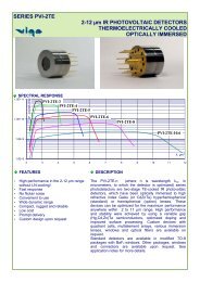
<strong>TE</strong>-<strong>TC</strong><br />
<strong>Temperature</strong> <strong>Controller</strong> <strong>for</strong><br />
<strong>Thermoelectric</strong> <strong>Cooler</strong>s Manual<br />
1. Introduction<br />
The <strong>TE</strong>-<strong>TC</strong> is a precision temperature controller designed to control thermoelectric (Peltier)<br />
coolers <strong>for</strong> infrared detectors and light-emitting diodes.<br />
The controller senses temperature by measuring the resistance of a thermistor mounted on the<br />
cooler. The <strong>TE</strong>-<strong>TC</strong> operates with a one, two, or three stage Peltier cooler and thermistor<br />
temperature sensor. Control and display can be either in temperature or resistance units. The<br />
controller output current can also be displayed and the maximum cooler current can be set. Either<br />
the set point or actual value of temperature, resistance or current can be displayed.<br />
The <strong>TE</strong>-<strong>TC</strong> incorporates an RS-232 serial interface <strong>for</strong> computer communication and control.<br />
Additional features include automatic cooler shutdown when thermistor short or open circuit is<br />
detected.<br />
PLEASE READ THIS GUIDE BEFORE USING THE CONTROLLER<br />
2. Control Principle<br />
The <strong>TE</strong>-<strong>TC</strong> employs a full three-term digital control algorithm to control the temperature,<br />
minimizing overshoot, eliminating steady-state temperature error and allowing fast settling time<br />
to a selected temperature. For set temperatures above ambient, the controller reverses the current<br />
polarity to <strong>for</strong>ce the Peltier device to act as a heater, enabling a controlled temperature range<br />
from –42° to +32° Celsius.<br />
3. Controls<br />
The front panel consists of:<br />
• 4 digit <strong>LED</strong> display<br />
• MODE push button and <strong>LED</strong> indicators, selecting either SET or READ SET displays the<br />
set value in the selected units. READ displays the actual value of the selected unit.<br />
• UNITS push button and <strong>LED</strong> indicators, selecting either temperature (T), resistance (R)<br />
or current (I).<br />
• Increase (INC) and decrease (DEC) push buttons, to adjust the setpoint temperature or<br />
resistance.<br />
Boston Electronics Corporation, 91 Boylston Street, Brookline MA 02445<br />
(800)347-5445 or (617)566-3821 * fax (617)731-0935 * boselec@boselec.com * www.boselec.com
• Current limit potentiometer (screwdriver slot) used to adjust the maximum allowable<br />
output current.<br />
• Power ON/OFF switch - AC inlet ON/OFF (on Rear Panel).<br />
• OUTPUT switch, controlling current to the coolers.<br />
4. Connecting the <strong>Cooler</strong> and Thermistor<br />
1. Unplug the <strong>TE</strong>-<strong>TC</strong> controller from the AC supply.<br />
2. Attach the leads from the Peltier cooler to the connector on the rear panel. See Appendix<br />
1 <strong>for</strong> wiring details.<br />
WARNING! The supplied current can KILL. Ensure that the controller is unplugged from the<br />
power and turned OFF.<br />
CAUTION! Observe the correct polarity. Reversed connections will cause overheating and<br />
possible failure of the cooler and any device mounted on it.<br />
The cooler connections must not be grounded.<br />
3. Attach the leads from the thermistor to the connector on the rear panel. See Appendix 1<br />
<strong>for</strong> details.<br />
CAUTION! The controller is normally calibrated to a linearised thermistor having a resistance<br />
of 8.2kΩ+/-5% at 25°C. (Betatherm 8.2KΩ MCDG). If any other variety of thermistor is to be<br />
used, the <strong>TE</strong>-<strong>TC</strong> must either be factory calibrated or used in CONTROL<strong>LED</strong> RESISTANCE<br />
mode (see section 8 below). Use of CONTROL<strong>LED</strong> <strong>TE</strong>MPERATURE mode in this<br />
circumstance will lead to gross temperature errors and possible damage to the cooler and any<br />
device mounted on it.<br />
The Thermistor connections must not be grounded.<br />
5. Identification of <strong>Controller</strong><br />
As the calibration of the <strong>TE</strong>-<strong>TC</strong> controller depends on the type of thermistor used, the unit can<br />
display an identification code to identify the calibration permanently stored in its memory. To<br />
display the identification code: Press and hold down the MODE key whilst switching on. The<br />
code will be displayed until the MODE key is released. The code <strong>for</strong> specially-calibrated units is<br />
"SP-X where X is a number. The variations from the standard setting, if programmed, are<br />
described in Appendix 2. The standard code is AP-1.<br />
Boston Electronics Corporation, 91 Boylston Street, Brookline MA 02445<br />
(800)347-5445 or (617)566-3821 * fax (617)731-0935 * boselec@boselec.com * www.boselec.com
6. Setting the Current Limit<br />
1. Plug the controller into the power and switch power ON.<br />
2. Ensure the OUTPUT is OFF.<br />
3. Using the push buttons, select SET mode and I units to display current.<br />
4. Using a small screwdriver, adjust the current limit potentiometer until the display shows<br />
the desired value in amperes.<br />
NO<strong>TE</strong>: Adjusting the potentiometer at any time will adjust the maximum current, whether or not<br />
it is displayed. It is advisable to initially set to half the recommended current <strong>for</strong> the Peltier<br />
cooler being used. The current can subsequently be increased if inadequate.<br />
7. Setting the Operating <strong>Temperature</strong><br />
The set point units (i.e. temperature or resistance) must be selected and set be<strong>for</strong>e switching the<br />
controller output to ON. Once the output is activated, only the initial setpoint units can be altered<br />
in SET mode; all other units can only be read.<br />
1. Set output to OFF.<br />
2. Select T units <strong>for</strong> temperature.<br />
3. Select SET mode.<br />
4. Using the INC and DEC push buttons, increase or decrease the setting. Holding down the<br />
buttons increases the speed of change.<br />
NO<strong>TE</strong>: <strong>Temperature</strong>s BELOW 0°C are displayed without a minus sign and with 0.01°C<br />
precision. For example, -18.5°C is displayed as 18.50. <strong>Temperature</strong>s ABOVE zero are shown<br />
with a plus sign: e.g. 14°C is displayed as +14.0.<br />
CAUTION! CONTROL<strong>LED</strong> <strong>TE</strong>MPERATURE mode should be used only with linearised<br />
thermistors having a resistance of 8.2 kilohms at 250 C. For other thermistors, see Section 8<br />
below.<br />
5. Turn output to ON. The controller will supply current to the cooler to bring the actual<br />
temperature to the setpoint value.<br />
With output ON, the actual thermistor resistance, cooler temperature and current can be viewed<br />
by selecting READ mode and the appropriate units.<br />
8. Setting the Operating Resistance<br />
If a non-standard thermistor is used, the temperature calibration of the controller is not valid;<br />
instead, the thermistor resistance must be monitored and controlled.<br />
1. Consult the thermistor specifications to determine its resistance at the desired setpoint<br />
temperature.<br />
Boston Electronics Corporation, 91 Boylston Street, Brookline MA 02445<br />
(800)347-5445 or (617)566-3821 * fax (617)731-0935 * boselec@boselec.com * www.boselec.com
2. Set output to OFF.<br />
3. Select R units <strong>for</strong> resistance.<br />
4. Select SET mode.<br />
5. Use the INC or DEC push buttons to increase or decrease the setpoint <strong>for</strong> resistance.<br />
6. Turn output to ON. The controller will supply current to the cooler to bring the measured<br />
resistance to the setpoint value.<br />
NO<strong>TE</strong>: A resistance range <strong>for</strong> 2OOKΩ to 6.7KΩ may be used, Above 200KΩ the controller<br />
assumes an open circuit and displays –0C-. Below 50Ω, a short circuit is assumed and -SC- is<br />
displayed.<br />
With output ON, the actual thermistor resistance or cooler current can be viewed by selecting<br />
READ mode and the appropriate units. Note that the displayed temperature will NOT be correct.<br />
9. Display Format<br />
As explained above, temperature is displayed to four significant figures below 0°C and to three<br />
figures above 0°C; e.g. -30.45°C is shown as 30.45, while 10.23°C is shown as<br />
10.22 Resistance is displayed in kilohms to four figures. For example, 12 kilohms is shown as<br />
12.00 and 120 kilohms as 120.0.<br />
Current is displayed as a three figure value in amperes, with a resolution of 0.02A.<br />
-OC- indicates an open circuit <strong>for</strong> the thermistor.<br />
-SC- indicates a short circuit <strong>for</strong> the thermistor.<br />
10. RS-232 Serial Interface<br />
The serial interface allows communication with a computer. This section describes interfacing<br />
details.<br />
10.1 Description<br />
The interface is implemented as a simple three-wire system which uses software handshaking<br />
procedures to allow the system to work with any computer having an RS232 type serial I/O port.<br />
10.2 Pin-outs<br />
The connector pin-outs are shown in figure 1. A 9-pin D connector is assumed at the computer<br />
end; if this is not the case, pin numbers will change. A null modem cable may be used since no<br />
other pins are connected at the <strong>TE</strong>-<strong>TC</strong> controller end.<br />
10.3 Communication Protocol<br />
4800 baud<br />
1 start bit<br />
8 data bits<br />
no parity (if there is, it is ignored)<br />
1 or 2 stop bits<br />
Boston Electronics Corporation, 91 Boylston Street, Brookline MA 02445<br />
(800)347-5445 or (617)566-3821 * fax (617)731-0935 * boselec@boselec.com * www.boselec.com
RS232 9-way D-plug on controller<br />
Pin No Usage<br />
2 TXD - output from <strong>TE</strong>-<strong>TC</strong><br />
S RXD - input to <strong>TE</strong>-<strong>TC</strong><br />
5 Ground<br />
10.4 Handshaking<br />
Handshaking (i.e. verification of proper communication) is per<strong>for</strong>med by a character echoing: a<br />
character sent to the temperature controller causes a reply with either the same character, data, or<br />
an error character. There is no further response from the temperature controller until another<br />
command is sent. A ‘character’ is any valid ASCII code <strong>for</strong> upper case characters, numbers 0 to<br />
9, ".","+", and "".<br />
Command characters are T, R, S, L, G, and H. These are always echoed.<br />
10.5 Units selection<br />
Select R to select resistance units.<br />
Send T to select temperature units.<br />
The <strong>LED</strong>'s on the front panel will respond in the same manner as if the front panel controls were<br />
being used. Note that the front panel controls will still operate when remote commands are sent.<br />
It is good practice to use only the RS232 link when operating remotely to avoid confusion.<br />
Send G (<strong>for</strong> GO) to turn on the output.<br />
Send H (<strong>for</strong> HALT) to switch off the output.<br />
Send L to load the setpoint once T or R has been selected.<br />
The standard procedure is as follows:<br />
Send T or R (wait <strong>for</strong> echo)<br />
Send L (wait <strong>for</strong> echo)<br />
Send setpoint data, character by character, waiting after each character <strong>for</strong> its echo.<br />
The exact data <strong>for</strong>mat must be followed; otherwise the temperature controller will not accept the<br />
data and will send an error character.<br />
• For resistance setpoints, send four digits with decimal point; e.g. 123.245KΩ is sent as<br />
123.3<br />
• For negative temperatures, send first two numbers, then decimal point, and finally two<br />
numbers; e.g. 17.42 <strong>for</strong> –17.42°C.<br />
• For positive temperatures, send first a ‘plus’ sign, the two numbers, then decimal point<br />
and finally one number, e.g. +07.6 <strong>for</strong> + 7.6°C. For example, to set a temperature of -<br />
12.32°C via RS 232 follow this procedure:<br />
Send T<br />
Send L<br />
Send 1<br />
(await echo)<br />
(await echo)<br />
(await echo)<br />
Boston Electronics Corporation, 91 Boylston Street, Brookline MA 02445<br />
(800)347-5445 or (617)566-3821 * fax (617)731-0935 * boselec@boselec.com * www.boselec.com
Send 2<br />
Send .<br />
Send 3<br />
Send 2<br />
(await echo)<br />
(await echo)<br />
(await echo)<br />
(await echo)<br />
The front panel should now show SET mode, <strong>TE</strong>MPERATURE units and a display of 12.32.<br />
Any <strong>for</strong>mat error will result in a “D” being sent by the <strong>TE</strong>-<strong>TC</strong> after the last number. Any<br />
unrecognized character will be echoed by "Q" (<strong>for</strong> Query); this will also cause the controller to<br />
revert to normal idle state, awaiting another command or setpoint.<br />
The controller automatically loads the setpoint value after receiving five characters, including the<br />
decimal point, providing they are valid characters and the decimal point is correctly positioned.<br />
For example, 12.345 would be accepted as 12.34 but a"" would be returned on receipt of the “5”<br />
which would be interpreted as an unrecognized command.<br />
10.6 Reading Actual Values<br />
Send T or R<br />
Send S<br />
Send X<br />
Send X<br />
to select temperature or resistance. (await echo)<br />
to order the value to read into an output buffer. (await Echo)<br />
to receive the first digit of the value. The digit character will be sent<br />
without echoing the “X”.<br />
to receive the other four characters, repeat “X”.<br />
For example, to read a temperature of -21.59°C, follow this procedure:<br />
COMPU<strong>TE</strong>R <strong>TE</strong>-<strong>TC</strong> REPLY<br />
T<br />
T<br />
S<br />
S<br />
X 2<br />
X 1<br />
X .<br />
X 5<br />
X 9<br />
If another S or any other character other than “X” is sent while data is being transferred, the old<br />
command will be cleared and the new command will be carried out More than five “X”<br />
characters will be echoed by “E” <strong>for</strong> 'END'.<br />
10.7 RS-232 Command Summary<br />
Control character<br />
T<br />
R<br />
S<br />
X<br />
L<br />
G<br />
H<br />
Action<br />
Select temperature units<br />
Select resistance units<br />
Read temperature or resistance<br />
Send next character of the measured value<br />
Load setpoint value<br />
Go (turn output on)<br />
Halt (turn output off)<br />
Error Character<br />
Meaning<br />
Boston Electronics Corporation, 91 Boylston Street, Brookline MA 02445<br />
(800)347-5445 or (617)566-3821 * fax (617)731-0935 * boselec@boselec.com * www.boselec.com
D Decimal point wrongly placed or missing<br />
Q Invalid data character<br />
Unrecognized command<br />
E End of buffer<br />
11. Improving <strong>Temperature</strong> Stability<br />
If the controller is being used at a temperature which needs much less than the maximum<br />
allowable current <strong>for</strong> the Peltier cooler, the temperature can sometimes be improved by<br />
decreasing the set current limit. To reduce the set current, first check the operating current at the<br />
set temperature whilst the controller is operating. Select READ mode and I units. Next set the<br />
current limit to about 10 to 20% greater than the required value. Switch to READ mode and<br />
temperature units again to see if the temperature has stabilized. Note that it may take a little<br />
longer to reach a set value. If the set value is not regained, increase the current limit slightly and<br />
repeat.<br />
NO<strong>TE</strong>: If the Peltier cooler has inadequate capacity to reach the set temperature, the controller<br />
will supply the maximum allowable current. <strong>Temperature</strong> stability is likely to suffer.<br />
12. Specifications<br />
Sensor Type<br />
Thermistor (8.2KΩ @ 25°C)<br />
Sensor Current 10 µA<br />
Output Stage<br />
Bipolar, constant current type<br />
Output Current Range<br />
0 to 2.0 amperes<br />
Maximum Output Voltage<br />
3 volts<br />
<strong>Temperature</strong> Range (with calibrated Thermistor) -42°C to +32°C<br />
Thermistor Resistance Range<br />
200KΩ to 6.7KΩ<br />
<strong>Temperature</strong> Setting Readout Resolution below 0.01°C<br />
100KΩ<br />
Resistance Setting and Readout Resolution 10Ω<br />
below 100KΩ<br />
Short-term <strong>Temperature</strong> Stability (using +/- 0.01°C<br />
calibrated thermistor)<br />
Ambient <strong>Temperature</strong> Tempco<br />
50 ppm/°C<br />
Current Limit set and Readout Range 0 to 2.5A<br />
Display<br />
4 digit seven segment <strong>LED</strong><br />
Serial Interface<br />
RS-232 compatible<br />
Protection<br />
Automatic shutdown <strong>for</strong> open or<br />
short circuit of thermistor<br />
Power Requirement<br />
115 or 220V AC (+/- 10%) @ 24VA<br />
Identification<br />
AP-1<br />
Boston Electronics Corporation, 91 Boylston Street, Brookline MA 02445<br />
(800)347-5445 or (617)566-3821 * fax (617)731-0935 * boselec@boselec.com * www.boselec.com
Appendix 1: <strong>Cooler</strong>/Thermistor Connector<br />
The back panel includes RS232 connector, AC power switch and cooler/thermistor connector.<br />
The cooler/thermistor connector is used both <strong>for</strong> thermistor input and cooler output. One 9-pin<br />
D-plug to 9-pin D-plug is supplied with the controller.<br />
The plug is wired as follows:<br />
Pin Number Connection<br />
6 <strong>Cooler</strong> positive<br />
1 <strong>Cooler</strong> negative<br />
5 Thermistor<br />
9 Thermistor<br />
The AC fuse is internal - lA <strong>for</strong> 240V AC, 2A <strong>for</strong> 120V AC.<br />
Appendix 2: Special settings <strong>for</strong> SP-1 Calibrated Units<br />
1. The thermistor resistance varies nonlinearly with temperature (see Fig 2)<br />
2. Sensor current is 100uA.<br />
3. The open circuit symbol (-OC-) is displayed <strong>for</strong> resistance above 17KΩ instead of<br />
200KΩ.<br />
4. For thermistor resistance below 10KΩ, the display and RS-232 <strong>for</strong>mats are to 1Ω<br />
resolution, not of 10KΩ resolution.<br />
Appendix 3: Calibration of the Thermistor Probe, standard unit AP-1<br />
The following data has been used to calibrate the Type 8.2K7MCD6 thermistor:<br />
Resistance <strong>Temperature</strong> °C Resistance <strong>Temperature</strong> °C<br />
178423.1 -40 23165.13 0<br />
134078.2 -35 18582.49 5<br />
101723.2 -30 15005.79 10<br />
77882.2 -25 12194.57 15<br />
60147.8 -20 9970.69 20<br />
46839.5 -15 8199.88 25<br />
36766.07 -10 6781.67 30<br />
29077.81 -5 5638.84 35<br />
4712.54 40<br />
Boston Electronics Corporation, 91 Boylston Street, Brookline MA 02445<br />
(800)347-5445 or (617)566-3821 * fax (617)731-0935 * boselec@boselec.com * www.boselec.com
Appendix 4: Identification of Units<br />
Press the mode key when switching ON: an identification code will appear on the display until<br />
the mode key is released. For standard unit it is AP-1.<br />
For SP-3 Unit<br />
This unit is calibrated against the RT curve supplied (see appendix 3 <strong>for</strong> standard RT curve),<br />
with end curve extrapolation to –27°C and +20°C. The excitation current is<br />
100uA.<br />
- OC- will be displayed and unit will shut off load power. If the resistance goes above 17KΩ,<br />
then the display will be – SC - (i.e. very low input resistance).<br />
The RS 232 <strong>for</strong>mat differs only <strong>for</strong> transmitted resistance value (i.e. 1.2K is sent as 1.200 with<br />
normal units this would be 01.20). Resistance is now displayed with a resolution of 1Ω <strong>for</strong><br />
resistance values below 10KΩ.<br />
NO<strong>TE</strong>: Both sensor inputs and cooler output connections must not be grounded.<br />
Propriety Notice<br />
This publication contains in<strong>for</strong>mation partly derived from propriety data of Laser Monitoring<br />
Systems. The express purpose of this in<strong>for</strong>mation is to assist in the operation and maintenance of<br />
the equipment described herein. The publication of this in<strong>for</strong>mation does not convey any right to<br />
reproduce or use the in<strong>for</strong>mation <strong>for</strong> any purposes other than in the operation or maintenance of<br />
the equipment described herein.<br />
Disclaimer<br />
Laser Monitoring shall not be liable <strong>for</strong> any incidental or consequential damages in connection<br />
with any deletions, errors or omissions in this manual.<br />
It is the user's responsibility to use the controller as described in this manual. Using too high a<br />
limiting current or an incompatible thermistor, or an inadequate heatsink could damage the<br />
Peltier cooler and/or any device mounted on it.<br />
Laser Monitoring Systems Limited disclaims all responsibility <strong>for</strong> damage caused by misuse of<br />
the <strong>TE</strong>-<strong>TC</strong> controller Evidence of misuse will void the warranty.<br />
Boston Electronics Corporation, 91 Boylston Street, Brookline MA 02445<br />
(800)347-5445 or (617)566-3821 * fax (617)731-0935 * boselec@boselec.com * www.boselec.com
Boston Electronics Corporation, 91 Boylston Street, Brookline MA 02445<br />
(800)347-5445 or (617)566-3821 * fax (617)731-0935 * boselec@boselec.com * www.boselec.com