Scitec Model 430 Board-Level Single Phase Lock-in Amplifier
Scitec Model 430 Board-Level Single Phase Lock-in Amplifier
Scitec Model 430 Board-Level Single Phase Lock-in Amplifier

Create successful ePaper yourself
Turn your PDF publications into a flip-book with our unique Google optimized e-Paper software.
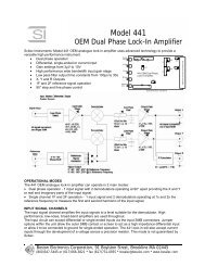
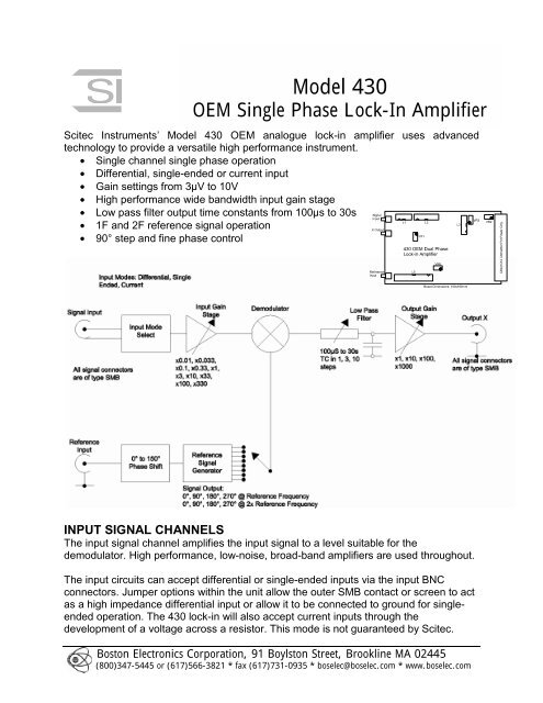
<strong>Model</strong> <strong>430</strong>OEM <strong>S<strong>in</strong>gle</strong> <strong>Phase</strong> <strong>Lock</strong>-In <strong>Amplifier</strong><strong>Scitec</strong> Instruments’ <strong>Model</strong> <strong>430</strong> OEM analogue lock-<strong>in</strong> amplifier uses advancedtechnology to provide a versatile high performance <strong>in</strong>strument.• <strong>S<strong>in</strong>gle</strong> channel s<strong>in</strong>gle phase operation• Differential, s<strong>in</strong>gle-ended or current <strong>in</strong>put• Ga<strong>in</strong> sett<strong>in</strong>gs from 3µV to 10V• High performance wide bandwidth <strong>in</strong>put ga<strong>in</strong> stage• Low pass filter output time constants from 100µs to 30s• 1F and 2F reference signal operation• 90° step and f<strong>in</strong>e phase controlINPUT SIGNAL CHANNELSThe <strong>in</strong>put signal channel amplifies the <strong>in</strong>put signal to a level suitable for thedemodulator. High performance, low-noise, broad-band amplifiers are used throughout.The <strong>in</strong>put circuits can accept differential or s<strong>in</strong>gle-ended <strong>in</strong>puts via the <strong>in</strong>put BNCconnectors. Jumper options with<strong>in</strong> the unit allow the outer SMB contact or screen to actas a high impedance differential <strong>in</strong>put or allow it to be connected to ground for s<strong>in</strong>gleendedoperation. The <strong>430</strong> lock-<strong>in</strong> will also accept current <strong>in</strong>puts through thedevelopment of a voltage across a resistor. This mode is not guaranteed by <strong>Scitec</strong>.Boston Electronics Corporation, 91 Boylston Street, Brookl<strong>in</strong>e MA 02445(800)347-5445 or (617)566-3821 * fax (617)731-0935 * boselec@boselec.com * www.boselec.com
The <strong>in</strong>put channels are DC coupled rather than the more normal AC coupl<strong>in</strong>g seen onother lock-<strong>in</strong> amplifiers as the noise performance is improved.InputSensitivityInput ImpedanceFrequencyMaximum InputsNoiseDifferential or s<strong>in</strong>gle ended voltage or current <strong>in</strong>put via SMB socket3µV to 10V <strong>in</strong> 1, 3, 10 steps. The <strong>in</strong>put ga<strong>in</strong> is set us<strong>in</strong>g jumpers enabl<strong>in</strong>g simplega<strong>in</strong> changes. One set of ga<strong>in</strong> resistors are mounted on solder pillars so that theycan be easily changed by the user with the aid of a solder<strong>in</strong>g iron.10 12 Ω⎪⎜1nF, dc coupled10Hz to 100kHz±10V before saturation occurs.<strong>Scitec</strong> Instruments no longer specifies <strong>in</strong>put noise values as this leads tocomparison with other manufacturers data sheets which are clearly grossly <strong>in</strong> error.If you wish for details of these values then please contact us and we will expla<strong>in</strong> thesituation.Ga<strong>in</strong> Accuracy 1%Ga<strong>in</strong> Stability 200ppm/°CDynamic Reserve 0dB to 80dB adjustable via jumpers.DEMODULATORThe <strong>in</strong>put stage drives a high performance demodulator to recover the <strong>in</strong>put signal.OUTPUTThe demodulator output is passed through a low pass filter before be<strong>in</strong>g amplified foroutput.Low Pass Filter Time ConstantOutputs - SMB connectors100µS to 30s <strong>in</strong> 1, 3, 10 steps. The time constant is set us<strong>in</strong>g jumpersenabl<strong>in</strong>g simple time constant changes. One set of resistor capacitorvalues are mounted on solder pillars so that they can be easilymodified with the aid of a solder<strong>in</strong>g iron.±100mV to ±10V full scale output. Can be modified through jumpersett<strong>in</strong>gs.REFERENCE CHANNELThe reference signal is used to generate the signals that drive the demodulator.A f<strong>in</strong>e phase shift<strong>in</strong>g circuit allows the reference signal to be phase shifted from 0° to150° with relation to the signal <strong>in</strong>put. A second circuit then produces signals that arephase shifted by 0°, 90°, 180° and 270° at both the reference frequency and twice thereference frequency. Any of these 8 signals can be used to drive the demodulator.Frequency10Hz to 100kHzTriggerStandard TTL, 95% mark/space ratio m<strong>in</strong>. Ris<strong>in</strong>g edge triggered.Acquisition time 10s max.<strong>Phase</strong> control 90° steps + f<strong>in</strong>e shift <strong>in</strong> range 0° - 150°<strong>Phase</strong> Drift0.1°/°C1F and 2F operationGENERALPower -15V, 0V, +5V, +15V DC @ 35mA per supply. Power connections are made via 64p<strong>in</strong> type C DIN41612 connector. Signal connections are not possible via thisconnector.Mechanical100 x 160mmTemperature range 0-50°C (operational)Warranty2 years from date of shipmentBoston Electronics Corporation, 91 Boylston Street, Brookl<strong>in</strong>e MA 02445(800)347-5445 or (617)566-3821 * fax (617)731-0935 * boselec@boselec.com * www.boselec.com