Temperature vs Voltage - Boston Electronics Corporation
Temperature vs Voltage - Boston Electronics Corporation
Temperature vs Voltage - Boston Electronics Corporation

Create successful ePaper yourself
Turn your PDF publications into a flip-book with our unique Google optimized e-Paper software.
INFRAREDSOURCESCalibration GradeBlackbodiesCalibration GradeExtended AREA BlackbodiesMiniature InstrumentGrade BlackbodiesIR LEDsTunable IR DiodePb-salt LasersNEW Tunable IR DiodeQuantum Cascade Lasers• 0.5, 1 and 2.25inch aperture• 325 to 1475 K• 2x2 and 12x12inch• -30 to +140C and20 to +350C• Near to Far IR• CW andModulated• 1.8, 2.8, 3.4, 4.2 ,4.8, & 4 to 7 µm• 3.1 to 10 µm• Cryogenic• 3.5 to 17 + µm• Room temp orcryogenic• Pulsed or CW<strong>Boston</strong> <strong>Electronics</strong> <strong>Corporation</strong>91 Boylston Street, Brookline MA 02445 USA(800)347-5445 or (617)566-3821 fax (617)731-0935www.boselec.com irsource@boselec.com07/01/2004 \\Snap105913\share1\Product Literature\IR Sources\xPages used in print version\Cover Infrared Sources 6-04.doc
Thermal Emitter <strong>Temperature</strong>and Color CorrelationCentigrade Fahrenheit Color ( Apparent )400 752 Red heat visible in the dark474 885 Red heat visible in twilight525 977 Red heat visible in daylight581 1078 Red heat visible in sunlight700 1292 Dark red800 1472 Dull cherry red900 1652 Cherry red1000 1832 Bright cherry red1100 2012 Orange red1200 2192 Orange yellow1300 2372 Yellow white1400 2552 White welding heat1500 2732 Bright white1600 2912 Dazzling white (bluish white)<strong>Boston</strong> <strong>Electronics</strong> offers a range of infrared radiation sources, bothmodulated and unmodulated. Please ask for details.<strong>Boston</strong> <strong>Electronics</strong> <strong>Corporation</strong>, 91 Boylston Street, Brookline MA 02445(800)347-5445 or (617)566-3821 * fax (617)731-0935 * boselec@boselec.com * www.boselec.com
IR-12 SeriesMiniature 8 to 11 WattInfrared EmitterThis IR source is a thermal emitter with emissivity ~0.8. It is appropriate for use in lab or fieldinstrumentation due to its long life and stable properties.Dimensions in mmThe Series IR-12 is offered as follows:The coiled resistance wirefilament IR-12 operates at825 o C (1100K) when poweredwith 4.5 volts @ 1.8 amps (8watts). The IR-12K takeshigher electrical power andruns hotter. Emissivity is~80% in the IR. The coil iswound on a cylindricalalumina substrate. Operationin a controlled or sealedatmosphere is not required.The emitter coil is mountedhorizontally on an 8.5 mm dia.base. The emitter supportpins also are the power leadsand are sealed in glass.Part #IR-12IR-12KDescriptionStandard unit – powerapprox 8 watts at 825CMechanically identical tostandard unit but capableof higher temp operationFor Long Service Life(Temp @ Volts, Amps)825C @ ~4.5V, 1.8 ALifetime > 3 years975C @ ~6.0V, 1.8 ALifetime > 3 yearsRecommendedUpper Limit1025C at ~6V, 2.4 A1125C at ~7V, 2.2 A<strong>Boston</strong> <strong>Electronics</strong> can also supply custom designed miniature IR blackbody sources.Please inquire.<strong>Boston</strong> <strong>Electronics</strong> <strong>Corporation</strong>, 91 Boylston Street, Brookline MA 02445(800)347-5445 or (617)566-3821 * fax (617)731-0935 * boselec@boselec.com * www.boselec.comI:\Product Literature\IR Sources\IR-12.doc
Distributed by <strong>Boston</strong> <strong>Electronics</strong>91 Boylston St, Brookline MA 02445(800)347-5445 or (617)566-3821fax (617)731-0935irsource@boselec.com www.boselec.comIR-12 Steady State Infrared EmitterENGINEERING DATA<strong>Temperature</strong> <strong>vs</strong> <strong>Voltage</strong>Dimensions12003+ Year LifeUpper LimitCentigrade10008006004002002 3 4 5 6VoltsAll dimensions in mmCurrent <strong>vs</strong> <strong>Voltage</strong>Power <strong>vs</strong> <strong>Voltage</strong>33+ Year Life163+ Year LifeAmps21Watts128402 3 4 5 602 3 4 5 6VoltsVoltsHawkEye Technologies LLC is a custom fabricator of IR sources. We will customize our existing products toyour design specifications. We would be pleased to quote a new custom IR source, including engineering, thatwill meet your requirements.
Distributed by <strong>Boston</strong> <strong>Electronics</strong>91 Boylston St, Brookline MA 02445(800)347-5445 or (617)566-3821fax (617)731-0935irsource@boselec.com www.boselec.comIR-12K Steady State Infrared EmitterENGINEERING DATA<strong>Temperature</strong> <strong>vs</strong> <strong>Voltage</strong>Dimensions12003+ Years LifeUpper LimitCentigrade10008006004002002 3 4 5 6 7VoltsAll dimensions in mmCurrent <strong>vs</strong> <strong>Voltage</strong>Power <strong>vs</strong> <strong>Voltage</strong>33+ Year Life163+ Year LifeAmps21Watts128402 3 4 5 6 702 3 4 5 6 7VoltsVoltsHawkEye Technologies LLC is a custom fabricator of IR sources. We will customize our existing products toyour design specifications. We would be pleased to quote a new custom IR source, including engineering, thatwill meet your requirements.
INFRARED SYSTEMLC-IR-12 with ThermocoupleMonitored, Stabilizable IR SourceThis Infrared System consists of our standard 800C Series 12 Infrared Light Source, a Type-KThermocouple and optional digital thermometer.This unit is intended as a low cost standard unit for general use. These units have been usedas checks on Infrared Instruments such as thermometers and cameras. Emissivity value is notguaranteed but fairly constant. <strong>Temperature</strong> can be monitored quite precisely with this unit andcan be maintained constant with feedback to your power source.When power is applied to the Infrared Light Source the unit heats and the thermometergenerates a digital read out of the surface temperature. The thermocouple output can also beused as an input to the [user supplied] power supply system to control the source temperature.Nominal source power requirement is 1.8 amps at 5 volts to maintain 825C [1100K]. The unitcan be operated up to 1100K for long [3 + years] duration or at higher temperatures to 1400K forshorter durations. <strong>Temperature</strong>s from 300K up are easily achievable and operation cooler than1100K extends lifetime rapidly.Construction: The Type-K Thermocouplesensor is fabricated using special limit errorthermocouple wire. This wire is rated at +/-1.1 o C. The sensor is applied directly tothe coil of the Infrared Light Source. Hightemperature, low expansion, material isused to apply the sensor to the source.The thermocouple is terminated with astandard Type-K miniature plug. Otherthermocouple types can be supplied onrequest.Optional Digital Thermometer: Thesensor output probe can be pluggeddirectly into this unit. The meter accepts alltype K thermocouple probes with ANSImini connectors. Meter features: HOLDbutton to freezes reading, switch forreadouts in o F and o C. The display haslarge ½” digital features. Meter comes with9 volt battery.We will customize our existing products to your design specifications. We would be pleased toquote a new custom IR source, including engineering, which will meet your requirements.<strong>Boston</strong> <strong>Electronics</strong> <strong>Corporation</strong>, 91 Boylston Street, Brookline MA 02445(800)347-5445 or (617)566-3821 * fax (617)731-0935 * boselec@boselec.com * www.boselec.com
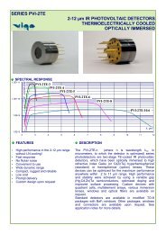
CS-IR-20 SeriesMiniature 4 Watt Infrared EmitterThis IR source is a thermal emitter with emissivity 0.8. It is appropriate for use in lab or fieldinstrumentation due to its long life and stable properties.The coiled resistance wire filament operates at 825C (1100K)when powered with 5 volts @ 0.8 amps (4 watts). Emissivity is~80% in the IR. The coil is wound on a cylindrical aluminasubstrate. Its low mass allows low frequency electricalmodulation to
Distributed by <strong>Boston</strong> <strong>Electronics</strong>91 Boylston St, Brookline MA 02445(800)347-5445 or (617)566-3821fax (617)731-0935irsource@boselec.com www.boselec.comIR-21 Steady State Infrared EmitterENGINEERING DATA<strong>Temperature</strong> <strong>vs</strong> <strong>Voltage</strong>Dimensions12003+ Year LifeUpper LimitCentigrade10008006004002002 3 4 5 6VoltsAll dimensions in mmVertical mounting shownAlso available mounted horizontallyCurrent <strong>vs</strong> <strong>Voltage</strong>Power <strong>vs</strong> <strong>Voltage</strong>1.53+ Year Life3+ Year Life6Amps10.5Watts4202 3 4 5 6Volts02 3 4 5 6VoltsHawkEye Technologies LLC is a custom fabricator of IR sources. We will customize our existing products toyour design specifications. We would be pleased to quote a new custom IR source, including engineering, thatwill meet your requirements.
Distributed by <strong>Boston</strong> <strong>Electronics</strong>91 Boylston St, Brookline MA 02445(800)347-5445 or (617)566-3821fax (617)731-0935irsource@boselec.com www.boselec.comIR-22 Steady State Infrared EmitterENGINEERING DATA<strong>Temperature</strong> <strong>vs</strong> <strong>Voltage</strong>Dimensions12003+ Year LifeUpper LimitCentigrade10008006004002002 3 4 5 6VoltsAll dimensions in mmHorizontal mounting shownAlso available mounted verticallyCurrent <strong>vs</strong> <strong>Voltage</strong>Power <strong>vs</strong> <strong>Voltage</strong>1.53+ Year Life63+ Year LifeAmps10.5Watts4202 3 4 5 6Volts02 3 4 5 6VoltsHawkEye Technologies LLC is a custom fabricator of IR sources. We will customize our existing products toyour design specifications. We would be pleased to quote a new custom IR source, including engineering, thatwill meet your requirements.
Hawkeye Technologies241 Research Drive #4Milford, CT. 06460INFRARED SOURCE SERIES 40THIN FILM INFRARED UNITThis Infrared Unit or gray body is a radiation emitter for use in Infrared instrumentation orlaboratory experimentationThe HawkEye Technologies Series 40 thin film unit operates at approximately 600° C whenpowered with 4 watts. The radiating element is an approximately 1.5 microns thick film ofprecision laser trimmed resistance material. The element is permanently bonded to a flatsubstrate of alumina forming a stable platform. This contributes to a uniform radiating source.The unit does not require operation in a sealed atmosphere. The thin film design results in alow mass of radiation material. This characteristic coupled with the excellent heat transferability of the alumina substrate provides the capability for electrical modulation.The IR-40 unit, shown below, is attached to a TO-5 header with high temperature cement.This unit is also offered without a cap (as an IR-40NC) and with a cap and sapphire window(as an IR-40S). For alternative mounting, it is also offered attached to a flat, butterfly shaped,steel header (as an IR-42).And now, announcing the NEW IR-43! This unit is free standing on a TO-5 header. Itrequires less power to achieve the same temperatures as the IR-40. Without a directlyconnected mass to draw off heat, it is more responsive.Operating SpecificationsUnit IR-40 New IR-43<strong>Temperature</strong> 600° C (875° Kelvin)Resistance 100 ohms<strong>Voltage</strong> 35 Volts (AC or DC)Current 115 milliamperesActive Area 3.5 mm X 2.5 mm600° C (875° Kelvin)50 ohms14 Volts (AC or DC)95 milliamperes1.5 mm X 1.5 mmIR-40HawkEye Technologies LLC is a custom fabricator of IR sources. We will customize our existing products toyour design specifications. We would be pleased to quote a new custom IR source, including engineering, thatwill meet your requirements.Distributor: <strong>Boston</strong> <strong>Electronics</strong> <strong>Corporation</strong>, 91 Boylston St, Brookline MA 02445 USA(80)347-5445 or (617)566-3821 * fax (617)731-0935 * irsource@boselec.com * www.boselec.com
Distributed by <strong>Boston</strong> <strong>Electronics</strong>91 Boylston St, Brookline MA 02445(800)347-5445 or (617)566-3821fax (617)731-0935irsource@boselec.com www.boselec.comIR-40 Infrared EmitterENGINEERING DATA (data collected with steady state voltage)<strong>Temperature</strong> <strong>vs</strong> <strong>Voltage</strong>Current <strong>vs</strong> <strong>Voltage</strong>Power <strong>vs</strong> <strong>Voltage</strong>HawkEye Technologies LLC is a custom fabricator of IR sources. We will customize our existing products toyour design specifications. We would be pleased to quote a new custom IR source, including engineering, thatwill meet your requirements.
Distributed by <strong>Boston</strong> <strong>Electronics</strong>91 Boylston St, Brookline MA 02445(800)347-5445 or (617)566-3821fax (617)731-0935irsource@boselec.com www.boselec.comIR-43 Infrared EmitterENGINEERING DATA (data collected with steady state voltage)<strong>Temperature</strong> <strong>vs</strong> <strong>Voltage</strong>800Upper LimitCentigrade60040020004 8 12VoltsCurrent <strong>vs</strong> <strong>Voltage</strong>Power <strong>vs</strong> <strong>Voltage</strong>0.152Amps0.10.05Watts1.510.504 8 12Volts04 8 12VoltsHawkEye Technologies LLC is a custom fabricator of IR sources. We will customize our existing products toyour design specifications. We would be pleased to quote a new custom IR source, including engineering, thatwill meet your requirements.
<strong>Boston</strong> <strong>Electronics</strong> <strong>Corporation</strong>, 91 Boylston Street, Brookline, MA 02445 (800)347-5445 or (617)566-3821 * fax (617)731-0935 *irsource@boselec.com * www.boselec.comBy Hawkeye Technologies LLCProducers of TomaTech Products Milford, CT. 06460INFRARED SOURCE SERIES 50Fast Electrically Modulated IR-50 Thermal SourceAnnouncing a NEW electrically modulated thermal source for 2 to 20 + microns. This new source isbased on patented new technology that utilizes a thin film of diamond-like carbon as the activeelement. It can be modulated up to 100 + Hz. It is therefore suitable for use with quantum detectorslike photoconductive PbS and PbSe, which otherwise would require a chopper to avoid excess lowfrequency "flicker" (1/f) noise.What distinguishes this new source from others is its high frequency of operation. That is, anelectrically modulated thermal source that exhibits good modulation depth, or contrast between theon and off states. This source is significantly better, watt for watt and Hz for Hz, than any competingnon-mechanical modulation that technology offers.This new source has an active area of approximately 1.5 mm 2 and is supplied in a TO-5 stylepackage. The normal working range is 500° to 750° C with peak short term heating up to 850° Cpossible. Calculated lifetime is approximately three years.Modulation Depth, Diamond-Like Thermal SourceDuty Cycle of 25 on, 75 offTypical Operating ParametersR [] in hot state 50I amplitude [mA] 145V amplitude [V] 6.9Input power [mW] 991HawkEye Technologies LLC is a custom fabricator of IR sources including TomaTech products. We willcustomize our existing products to your design specifications. We would be pleased to quote a new custom IRsource, including engineering, that will meet your requirements.08/02/2002
Distributed by <strong>Boston</strong> <strong>Electronics</strong>91 Boylston St, Brookline MA 02445(800)347-5445 or (617)566-3821fax (617)731-0935irsource@boselec.com www.boselec.comIR-50 Pulsable Infrared EmitterENGINEERING DATA (data collected with steady state voltage)<strong>Temperature</strong> <strong>vs</strong> <strong>Voltage</strong>1000Upper LimitCentigrade80060040020003 4 5 6 7 8VoltsCurrent <strong>vs</strong> <strong>Voltage</strong>Power <strong>vs</strong> <strong>Voltage</strong>0.16001.5Amps0.12000.0800Watts10.50.04003 4 5 6 7 8Volts03 4 5 6 7 8VoltsHawkEye Technologies LLC is a custom fabricator of IR sources. We will customize our existing products toyour design specifications. We would be pleased to quote a new custom IR source, including engineering, thatwill meet your requirements.
Distributed by<strong>Boston</strong> <strong>Electronics</strong> <strong>Corporation</strong>91 Boylston St, Brookline MA 02445 USA(800)347-4554 or (617)566-3821irsource@boselec.com * www.boselec.comIntroducing the New Collimated-Energy Pulsable IR-55!!The IR-55 is a MEMS technology electrically modulated infrared emitter built into a HawkEyeparabolic optic. The source is based on patented technology, utilizing a thin film of diamondlikecarbon as the active element for faster electric modulation. The parabolic packagecollimates the energy for greater on-axis intensity.This source is significantly better, watt for watt and Hz for Hz than any competing nonmechanicalmodulation technology.The IR-55 is truly in a class of its own!Excellent Modulation to 100 Hz and beyond!!Collimation provides 10x the Intensity!!This new source has an active area of 2.25 mm 2 and is supplied in a TO-5 style package.The normal working range is 500° to 750° C with peak short term heating up to 850° Cpossible. Calculated lifetime is approximately three years.The HawkEye IR-55 for Faster Electrical Modulation---50% Modulation Depth at over 100 Hertz!!!100%50% Duty Cycle25% Duty CycleDepth of Modulation50%0%1 10 100 1000Frequency in Hertz
IR-55 Nominal Parameters:<strong>Voltage</strong>*<strong>Temperature</strong>*Resistance in the Hot state*CurrentInput PowerCooling Time ConstantHeating Time ConstantModulation DepthActive areaLife6.4 volts (AC or DC)750° C50 ohms135 milliamps0.9 watts11.5 milliseconds35 milliseconds50% at 110 Hz, 25% Duty Cycle1.5 mm X 1.5 mm3+ years at 750° C typical*Measured at 5 Hz frequency, 50% duty cycle<strong>Temperature</strong> <strong>vs</strong> <strong>Voltage</strong>1000Upper LimitCentigrade80060040020003 4 5 6 7 8VoltsCurrent <strong>vs</strong> <strong>Voltage</strong>Power <strong>vs</strong> <strong>Voltage</strong>0.16001.5Amps0.12000.0800Watts10.50.04003 4 5 6 7 803 4 5 6 7 8VoltsVoltsHawkEye Technologies LLC is a custom fabricator of IR sources including products. We will customizeour existing products to your design specifications. We would be pleased to quote a new custom IRsource, including engineering, that will meet your requirements.
The HawkEye Technologies IR-50 and IR-55Operational Guidelines - Application DataDistributed by<strong>Boston</strong> <strong>Electronics</strong> <strong>Corporation</strong>91 Boylston St, Brookline MA 02445 USA(800)347-4554 or (617)566-3821irsource@boselec.com * www.boselec.comThe HawkEye IR-50 Series utilizes a thin thermoresistive conducting film of amorphous (diamond-like) carbon. Infraredradiation is the result of heating this film by passing an electric current through it.The maximum temperature of the film should not exceed 750°C in continuous operation. A faint red luminescence of thefilm is observed during continuous operation at temperatures near 750°C. Short term heating up to 850°C is possible butwill reduce the lifetime of the unit.The specifications shown below assume an infrared source operating without a radiator and at ambient temperature andpressure. A rectangular voltage pulsed at a frequency of 5 hertz and with a duty cycle of 50% is used for heating. Twopower leads and a ground are provided per the sketch below. Bi-polar drive voltage may be used.NominalParameters(750°C)MaximalParameters(750°C)Resistance in Hot State (Ohms) 50Current (mAmps) 135<strong>Voltage</strong> (volts) 6.4Input Power (Watts) 0.9Resistance in Hot State (Ohms) 50Current (mAmps) 150<strong>Voltage</strong> (volts) 7.5Input Power (Watts) 1.1The HawkEye IR-50 Series is the perfect solution for an application that requires fast electrical modulation. However, it canalso be used in a steady state (DC) mode. In applications where steady state power is used (or if used with electricalmodulation but with a duty cycle of greater than 50%), it is recommended that the nominal input power specifications not beexceeded in order to avoid overheating of the membrane.On the other hand, by reducing the length of the heating pulse or by increasing the frequency of modulation, the membranewill not have sufficient time to reach 750°C. In this case, the pulsed power can be increased to allow 750°C to bemaintained. The chart below shows the factor by which the voltage can be increased as frequency is increased. This chartassumes a 50% duty cycle.1.4Use this <strong>Voltage</strong> Ratioto maintain constant temperature.To Maintain<strong>Temperature</strong>,Increase Input<strong>Voltage</strong> by thisRatio1.31.21.111 10 100 1000Frequency (Hz) assuming a 50% duty cycleUsing a 50% duty cycle and the appropriate power factor as determined above, a 50% modulation depth is achievable atmodulation frequencies of more than 60 hertz. This modulation depth can be achieved at even higher frequencies (morethan 100 hertz) if a 25% duty cycle were used along with a correspondingly higher power factor (sufficient to maintain themembrane temperature at 750°C). Please contact HawkEye Technologies LLC for assistance in determining the properpower factor for the duty cycle to be used in your application.HawkEye Technologies LLC is a custom fabricator of IR sources. We will customize our existing products to your designspecifications. We would be pleased to quote a new custom IR source, including engineering, that will meet yourrequirements.
3/24/2004 <strong>Boston</strong> <strong>Electronics</strong> <strong>Corporation</strong>100%The IR-5x-series for >50% Modulation Depthat over 100 Hertz50%50% Duty Cycle25% Duty CycleDepth of Modulation0%1 10 100 1000Frequency in HertzHawkeye IR55 charts 10-22-03.xls Authorized Agents
3/24/2004 <strong>Boston</strong> <strong>Electronics</strong> <strong>Corporation</strong>The IR-5x-series has greater modulation depth than other products636040201016 161216HawkEye IR-55Source ASource BSource CSource DSource EHz for 50% Modulation Depth(using a 50% Duty Cycle)01.4Other Pulsating Sources in the Marketplace do not come close to the IR-55 Modulation Depth!!Hawkeye IR55 charts 10-22-03.xls Authorized Agents
100%80%60%40%20%0%The HawkEye IR-55 has Greater On-Axis Output by FarHawkEye IR-55 Source ASource B Source CSource D Source E0.9Input Power Required(in Watts per Manufacturer's Specs)Relative On-Axis Output Energy(with 1.75 inch spacing between emitter and detector)
Preliminary data sheetIon Optics, IncNew dimensions in IRmarkIR35Restricted BandInfrared SourceDESCRIPTION:FEATURES:• Viewing distance: 150 meters• NVG viewing distance:
Preliminary data sheetIon Optics, IncNew dimensions in IROPTICAL CHARACTERISTICS:Spectral Output Normalized Radiation Pattern0.06Power (W/cm 2 /µm)0.050.040.030.02markIR 35706050010 1020 2030 3040 405060700.0180800.002 4 6 8 10 12 14 16100% 75% 50% 25% 0% 25% 50% 75% 100%Wavelength (µm)PACKAGE OUTLINE:ELECTRICAL CONNECTIONS:6 and 22 Element #1 (power connection)8 and 20 Element #2 (power connection)1-5, 12-19, 26-28 Not connected7, 9, 10, 11, 21, 23, 24, 25 Test points (not for drive power)markIR is a trademark of Ion Optics, Inc.Ion Optics, Inc., 411 Waverley Oaks Road, Suite 144, Waltham, MA 02452Tel: 781-788-8777 ● Fax: 781-788-8811 ● E-mail: Info@Ion-Optics.com
Preliminary Data SheettūnIRCO 2Ion Optics, IncNew dimensions in IRTuned, Narrow BandInfrared SourceFEATURES:• Center wavelength: 4.25 µm• Spectral bandwidth: ±0.5 µm (FWHM)• Output Power: 0.5 mW (CO 2 band: 4.20-4.35 µm)• Output Power: 6.5 mW (2-6 µm)• Element Resistance: 150Ω each (two elements)• Total Input Power: 120 mW (3V dc at 40 mA)• Total Emitter Surface Area: 7.8 sq. mmBENEFITS:• Narrow emission band• Low drive power• No excess heat• Reduces or eliminates filtering requirementsDESCRIPTION:The tūnIR Infrared Light Source uses a two-dimensional photonic crystal structure to tune the IRemission to match the center wavelength of the target gas absorption line. This device has twoelements capable of being powered together (in series or parallel configuration) or separately. Each1.5 x 3 mm element has a resistance of 150Ω and requires 3V and 20 mA to operate. The IRspectrum from the tūnIR CO 2 devices, tuned for 4.25 µm, is shown in the optical characteristicsgraph.The tūnIR emitter is mounted in a ceramic leadless chip carrier. The package configuration andelectrical connections are described in the package outline drawings. Future generations of tūnIRdevices will utilize wafer-level packaging to achieve a more compact package.tūnIR sources are being developed for use with other gases, most notably combustiblehydrocarbons. Please contact Ion Optics to discuss applicability to other gas sensing applications.Devices for high volume applications can be customized with a second absorption or referencewavelength.APPLICATIONS:The narrow spectral output of tūnIR CO 2 is ideal for many applications now using discrete lamps andfilters, such as:‣ Respiration /capnography/ETCO 2‣ Indoor air quality‣ Enclosed space safety‣ Demand controlled ventilation‣ Exhaust gas analysis‣ Process controls/monitoringIon Optics, 411 Waverley Oaks Road, Suite 144, Waltham, MA 02452Tel: 781-788-8777 ● Fax: 781-788-8811 ● E-mail: Info@Ion-Optics.com
Preliminary Data SheetIon Optics, IncNew dimensions in IROPTICAL CHARACTERISTICS:Spectral Output Normalized Radiation Pattern0.06Power (W/cm 2 /µm)0.050.040.030.02tūnIR CO 276501 12 23 34 45670.01880.002 4 6 8 10 12 14 16100% 75% 50% 25% 0% 25% 50% 75% 100%PACKAGE OUTLINE:ELECTRICAL CONNECTIONS:6 and 22 Element #1 (power connection)8 and 20 Element #2 (power connection)1-5, 12-19, 26-28 Not connected7, 9, 10, 11, 21, 23, 24, 25 Test points (not for drive power)tūnIR is a trademark of Ion Optics, Inc.Ion Optics, 411 Waverley Oaks Road, Suite 144, Waltham, MA 02452Tel: 781-788-8777 ● Fax: 781-788-8811 ● E-mail: Info@Ion-Optics.com
pulsIRPulsed Infrared RadiatorDESCRIPTIONIon Optics offers a new class of electricallymodulated,high intensity infrared radiators for gasanalysis, spectroscopy and calibration. Theseradiators feature a low thermal-mass filamenttailored for high emissivity in either the MWIR (2-5m) or the LWIR (8-12m). Efficient in-bandemission permits operation at temperatures severaltimes cooler than tungsten bulbs and gives aradiator life exceeding 3 years. This patent-pending,high-efficiency device minimizes drive power,greatly reducing parasitic heating of detectors andoptics; it also eliminates mechanical choppers,permitting a sealed optical path.For demonstration and system design, Ion Opticsprovides a Developer’s Package, enabling users toexplore radiator characteristics over a wide range ofoperating pulse parameters and filamenttemperatures. This package consists of a pulsIRRadiator (LWIR or MWIR); pulsIR Driver, amicroprocessor-controlled drive card; andWindows TM compatible software designed formaximum performance and user friendliness. Thissystem minimizes input power and provides stableoperation at user-selected temperatures,frequencies, and duty cycles.pulsIR RadiatorOutput <strong>vs</strong>. Input PowerUNIQUE FEATURESElectrically pulsed, no chopper neededHigh intensity, 6x tungsten filament bulbsLarge temp. modulation, >500 o K below 10HzSpectrally tailored, efficient in-band radiationDigital drive, feedback temperature stabilizationAdaptable to DC operation<strong>Temperature</strong> Modulation<strong>Boston</strong> <strong>Electronics</strong> <strong>Corporation</strong>, 91 Boylston Street, Brookline MA 02445(800)347-5445 or (617)566-3821 * fax (617)731-0935 * boselec@boselec.com * www.boselec.com
MECHANICAL SPECIFICATIONSIR Source TO-5IR Source TO-8pulsIR Emission at 850 0 C.pulsIR Emitter SpecificationsLWIRMWIRCold Resistance 3.2 (±.5) 3.5 (±.5) Max Operating <strong>Temperature</strong> 850 o C 850 o CDrive PowerPeak 1.75 Watts 1.75 WattsAverage (@30% Duty cycle) .52 Watts .52 WattsEmissivityIn Band >.95 >.95Out of Band 3 yearsCycle)Part Number NL5NGC NM8ASCWindow ARGermanium Sapphire<strong>Boston</strong> <strong>Electronics</strong> <strong>Corporation</strong>, 91 Boylston Street, Brookline MA 02445(800)347-5445 or (617)566-3821 * fax (617)731-0935 * boselec@boselec.com * www.boselec.com
pulsIRApplications NoteBasic pulsIR operationIon Optics offers a new class of electrically-pulsed, high intensity infrared radiators for gas analysis,spectroscopy and calibration. These radiators feature an extremely low thermal-mass filament tailored forhigh emissivity in either the MWIR (2-5µm) or the LWIR (8-12µm) region. Low thermal mass combinedwith emissivity tailoring permits operation at lower input power levels for comparable output; therebylowering operational temperature and extending life. The increase in in-band emission also reducesparasitic heating effects. And by operating in a pulsed mode, the need for mechanical choppers iseliminated, simplifying system design.For most applications, pulsIR filaments should be run at duty cycles of less than 60%. Although capableof running at duty cycles of up to 100% (DC), the loss of temperature modulation with increasingduty/frequency generally reduces the utility of the device for most applications.Drive ConsiderationsGenerally, square-waveform constant current or constant voltage drive schemes are the simplest andmost cost effective means of powering pulsIR sources. For constant current drivers, the power deliveredto the source goes as I 2 R. As the source heats up, its resistance increases, causing the power deliveredto the source to increase during the "ON" portion of a pulse. For constant voltage drivers, delivered powergoes as V 2 /R; therefore the power delivered to the source tends to decrease during the length of a pulse.Other drive schemes can also be employed; constant power or DC for example.TO-8 Sized SourcesFor constant current, peak current should not exceed 0.8 amps. For constant voltage, peak voltageshould not exceed 2.8volts.TO-5 Sized SourcesFor constant current do not exceed 0.8 amps and for constant voltage do not exceed 2.5 volts.Further NotesThis application notes is designed to be a general aide in the use of the pulsIR radiators. There are no"cliffs edge" failure modes for the radiators; i.e. they may be driven harder than designed at the cost ofreduced lifetime. For your application, this may be an acceptable tradeoff.<strong>Boston</strong> <strong>Electronics</strong> <strong>Corporation</strong>, 91 Boylston Street, Brookline MA 02445(800)347-5445 or (617)566-3821 * fax (617)731-0935 * boselec@boselec.com * www.boselec.com
eflectIRCollimated Pulsed Infrared RadiatorUNIQUE FEATURESIntegrated reflectorImproved efficiencyMore axial IR powerLarge temperature modulationElectrically pulsedDESCRIPTIONThe new reflect IR series of electrically pulsed sources isdesigned for applications requiring high intensity infrared poweralong a narrow optical path. In this new package design theintegrated parabolic reflector focuses the output from the emitter tomaximize on-axis infrared power. These sources feature a low thermalmassemitter treated for high emissivity in the infrared, making them ideallysuited to non-dispersive infrared (NDIR) measurements with pyroelectric orthermopile detectors.Efficient in-band emission permits operation at temperatures several timescooler than tungsten bulbs and gives a radiator life exceeding 3 years.This patent-pending, high-efficiency device minimizes drive power, greatlyreducing parasitic heating of detectors and optics; it also eliminatesmechanical choppers, permitting a sealed optical path.DRIVE CONSIDERATIONSReflectIRs have a standard resistance of 1.8 +/- 0.2. Please note that thisis significantly lower than the resistance for a comparable pulsIR source.Generally, square-waveform constant current or constant voltage driveschemes are the simplest and most cost effective means of poweringreflectIR sources. For constant current drivers, the powerdelivered to the source goes as I 2 R. As the source heatsup, its resistance increases, causing the power delivered tothe source to increase during the “ON’ portion of a pulse.For constant voltage drivers, delivered power goes as V 2 /R,therefore the power delivered to the source tends todecrease during the length of a pulse. NO more than 1.7watts (instantaneous) should be delivered to a reflectIR.For constant current, peak current should not exceed 0.97amps. For constant voltage, peak voltage should notexceed 1.75V.Although both pulsIR and ReflectIR sources can beoperated DC, thermal stresses caused by non-uniformheating in the pulsIR filament limit DC operation. With theReflectIR, however, the filament is heated uniformly,significantly reducing thermal stress and allowing forcontinued DC operation at higher power levels.<strong>Boston</strong> <strong>Electronics</strong> <strong>Corporation</strong>, 91 Boylston Street, Brookline MA 02445(800)347-5445 or (617)566-3821 * fax (617)731-0935 * boselec@boselec.com * www.boselec.com
Broadband Pulsed Infrared Light Sources• Broadband IR light from 2-20 µm• Consistent Pulsed Operation• Large <strong>Temperature</strong> Modulation• Many Package and Window options• Evaluation Kit for Rapid PrototypingIon Optics offers a unique class of electrically pulsed, high intensity infrared radiators for gas analysis, spectroscopy,calibration and tactical infrared friend or foe applications. These radiators feature a low thermal-mass filament tailoredfor high emissivity. The filament is fabricated using a patented process that supplies more IR power output above 4um than while operating much cooler. This lower temperature operation reduces the chance of igniting combustiblegasses, improves power efficiency, and reduces the parasitic heating of the optics and detectors. These IR sourcesare typically pulsed at rates from ½ to 10 Hz with several hundred degrees of temperature modulation, allowing thedesign of smaller and simpler systems that do not require the added complexity of a mechanical chopper.For demonstration and system design, Ion Optics provides an Evaluation Kit that includes the light source of yourchoosing. The Evaluation Kit drive card produces a flat-topped current pulse of adjustable amplitude, length, andfrequency that runs with pre-programmed settings, or is connected to a PC for user control via Windows TM .PART NUMBERS/WINDOW OPTIONS:Parabola TO-8 TO-5 TO-46Windowless reflectIR-P1N NL8LNC NL5LNC NL46LNXSapphire2 to 5.25 umGermanium7 to 12 umCalciumFlouride2 to 9.5 umreflectIR-P1S NM8ASC NM5NSC N/AN/A N/A NL5NGC N/AreflectIR-P1C NL8ACC NL5NCC N/APage 1 of 4
SPECIFICATIONSParabola TO-8 TO-5 TO-46Rated<strong>Temperature</strong>MinimumResistanceMaximumResistanceMaximum Input<strong>Voltage</strong>*850 C 850 C 850 C 850 C1.4 Ohms 2.8 Ohms 2.5 Ohms 0.4 Ohms2.0 Ohms 4.5 Ohms 3.7 Ohms 1.0 Ohms1.75 VDC 2.8 VDC 2.6 VDC 0.9 VDC10 10OutputRadiationPattern + 50607030 degrees 95 degrees00 10 1020 2020 2030 3030 3040 4040 4050506070706050607080808080100% 75% 50% 25% 0% 25% 50% 75% 100%* Maximum <strong>Voltage</strong> based on typical resistance values.+ Full angle for 50% of peak power100% 75% 50% 25% 0% 25% 50% 75% 100%PULSED OPERATIONAlthough capable of running at duty cycles of up to 100 % (DC) most users run the filaments with duty cycles of lessthan 50%. Square-waveform constant current or constant voltage drive schemes are the simplest and most costeffective means of powering the sources. For constant current drives, the power delivered to the source goes as I 2 R.As the source heats up, its resistance increases slightly , causing the power delivered to the source to increase duringthe “ON” portion of a pulse. For constant voltage drives, delivered power goes as V 2 /R; therefore the power deliveredto the source tends to decrease slightly during the length of a pulse. Other drive schemes can also be employed;constant power or DC for example.Owing to the extremely low thermal mass of pulsIR emitters,shot-to-shot stability is directly related to drive circuitstability. Variations in drive pulses will translate intovariations in output. To determine this we used a liquidnitrogen cooled InSb detector available in our laboratory fordetecting energy in the 2-5 um range. The pulsIR sourcewas driven with a constant-voltage drive circuit that ensurespulse-to-pulse repeatability (standard deviation) of 5.3x10 -4 .Measurements of the InSb detector reading from 16seconds of 10 Hz operation was measured to have acomparable standard deviation of 6.8x10 -4 .PULSED/CHOPPED POWERMODULATION DEPTH120%100%80%60%40%20%0%0 5 10 15 20 25 30 35PULSE RATE (HZ)Page 2 of 4
SOURCE LIFETIMEThe following graph shows the results (to date) from an ongoing extended life test experiment using an Ion OpticsNM8ASC source. The source is being driven by a constant current drive board at 1 Hz, 30% duty cycle at anapproximate temperature of 650°C. Two pyroelectric detectors are monitoring the source output at two distinctwavelengths. In the following chart, the circles show the source output at 4.29 microns (CO 2 ) while the diamondsshow the output at 3.9 microns (reference). The detectors are mounted about four inches from the front face of thesource and a dry nitrogen purge is used to prevent water vapor and carbon dioxide in the lab air from affecting themeasurement. The temperature in the lab is not very well controlled however, and much of the variation (specificallythe bump at ≈2000 hours) is due to room temperature swings.The definition of failure, and thus the definition of lifetime, is very subjective as each system has unique sensitivity todrift (largely related to the A/D bandwidth). We have encountered several applications which define failure as >15%drift from the original power level, so we will adopt this definition for the purposes of this computation. The graphbelow shows that the median signal level from the 3.9 and 4.29 µm detectors is roughly 4 volts; the linear regressionfits to the raw data indicate that both of these signals are decreasing at a rate of 1x10 -5 volts/hour. With our assumedsignal drift tolerance of 15% and 4 volt signal level, we require a 0.6 volt signal change to signal failure of the lightsource [0.15 x 4]. With our measured rate of change being 1x10 -5 volts/hour it will take approximately 6.85 years ofcontinuous operation to obtain a 15% signal change [(0.6v)/(1x10 -5 v/hr)/(8760hrs/yr)]. Since many systems utilize theratio of the gas measurement to a reference, they are sensitive not to signal changes, but to change in the ratio of thetwo signals. With a measured slope of 1x10 -6 volts/hour and a 0.75 volt signal the same computation yields a lifetimeof 12.84 years.Since all of the known filament degradation mechanisms are temperature dependent, the time to 15% failure isstrongly dependent upon operating temperature or electrical power applied. Therefore, caution should be used inextrapolating these results to your application.5y = -1E-05x + 4.788Detector Signal (volts)4321y = -1E-05x + 3.20463.9 micron4.29 micronRatio 3.9/4.29y = -1E-06x + 0.669500 2,000 4,000 6,000 8,000 10,000 12,000 14,000 16,000Time (hours)Page 3 of 4
REFLECTIR PACKAGE DIMENSIONSTO-8 PACKAGE DIMENSIONSTO-5 PACKAGE DIMENSIONSTO-46 PACKAGE DIMENSIONS040128RPage 4 of 4
CH-10S and CH-20SModulated IR SourceFEATURES AND ADVANTAGESHybrid assemblies of our CH-series tuningfork choppers with our CS-IR-22-serieswirewound filament IR sources.Much higher frequencies than withcompeting technologies100% modulation depth at all frequenciesLong life (>3 years, more if the source isrun at
CH-60S Modulated IR SourceFEATURES AND ADVANTAGESLOW COSTJitter free operationHigh frequency stability (to 0.005%)Small sizeWithstands shock and vibrationHigh reliability, long lifeAccepts external clock inputPhase locking to an external inputCan be stopped in the "ON" or "OFF" positionNo radiated electromagnetic interference (EMI)Bright or dark bladeA BOXED chopper optionalSpecial pricing for OEM applicationsIntegrated IR EMITTER (BLACK BODY)5+ year projected service lifeDESCRIPTIONThe VARIABLE LOW FREQUENCY modulator Model CH-60S consists of a blade (vane) mounted on amotor with a limited rotation angle. The position of the blade follows the direction of the current in the motorwinding. Current in one direction will set the chopper to the open position and current in the other directionwill set the chopper to the closed position. Alternating the current will cause the blade to open and close thechopper at a frequency range from DC to 50Hz for the CH-60S. This method of chopping is jitter free. Highreliability and long life is achieved by eliminating the use of a brush type motor or gear heads.When used with DCH-60 Drive <strong>Electronics</strong> and an external clock input, a frequency stability of 0.005% ispossible. This ultra high stability cannot be achieved with a rotating chopper. The chopping operation islocked in phase to the clock input therefore no additional circuitry is needed for phase locking. The driveralso enables the user to set the chopper, when it is not running, in either a closed position or an open position.The chopper is especially suitable for low cost dedicated applications, OEM, built into an instrument/system,and for portable systems.<strong>Boston</strong> <strong>Electronics</strong> <strong>Corporation</strong>, 91 Boylston Street, Brookline MA 02445(800)347-5445 or (617)566-3821 * fax (617)731-0935 * boselec@boselec.com * www.boselec.com
SPECIFICATIONS (WHEN USED WITH DCH DRIVER)Aperture SizeFrequency RangeResponse Time, from OPENto CLOSED, or vice-versaPower Requirements,chopper with emitter anddriver boardChopper SizeChopper WeightSettling Time to ExternalClockExternal Clock InputFrequency StabilityMonitor OutputOperating <strong>Temperature</strong>Driver ConfigurationCH-600.25 x 0.45 inchDC to 50Hz10 mSec15V DC, 250mA and5V DC, 1.0Amp1.75”W x 3.0”H x 1.0”D2.5 Oz (70 grams)20 mSecCD to 50Hz TTL level input5V or OPEN to open the chopper0V or “GND” to close the chopper0.1% internal clock0.005% with external crystal clock inputTTL level output“Hi” indicates the chopper is open“Lo” indicates the chopper is closed0-65°CThe DCH-60 Driver is available in two configurations:Model DCH-60-PC: A board-level driverModel DCH-60-110/220: A cased driver, 5.3”x5.3”x2”,operating from a line voltage of 110V AC or 220V ACDCH DRIVER<strong>Boston</strong> <strong>Electronics</strong> <strong>Corporation</strong>, 91 Boylston Street, Brookline MA 02445(800)347-5445 or (617)566-3821 * fax (617)731-0935 * boselec@boselec.com * www.boselec.com
IR-140 and IR-160Extended Area Blackbody SourcesFEATURES Digital PID PLUSController 16 Interval Ramp toand Hold from FronPanel Two (2) CustomerConfigured AlarmRelays One Year Warranty RS-232C/422A/485 orIEEE-488(optional) Electronic Ice BathReference (optional) Digital Watts DisplayDESCRIPTIONOur line of large area targets for wide field of view instruments and radiant intensitystudies provide temperature ranges from ambient to 230°C and ambient to 350°C.These sources are coated with high emissivity (0.95 +/- 0.02) black finishes that areheat treated and durable enough for outdoor use. Independent temperature monitoringby means of a Type “T” thermocouple allows the user to accurately monitor the sourcetemperature under the toughest of conditions.IR-140 Blackbody SourceThe IR-140 blackbody provides high quality and reliability with a thermally immersedheater winding that provides maximum thermal conductivity and uniformity from ambientto 230°C. the 12 inch square surface is an ideal calibration or reference target fortoday’s large field of view imaging and target acquisition systems.IR-160 Blackbody SourceThe IR-160 blackbody has a temperature range from ambient to 350°C, increasingmaximum temperature over the IR-140, with slightly higher edge-to-edge uniformity. At350°C, the IR-160 provides ideal simulation of military targets, such as helicopter orcombat tank engines. The large are creates and easy-to-find target under simulatedbattlefield conditions.<strong>Boston</strong> <strong>Electronics</strong> <strong>Corporation</strong>, 91 Boylston Street, Brookline MA 02445(800)347-5445 or (617)566-3821 * fax (617)731-0935 * boselec@boselec.com * www.boselec.com
SPECIFICATIONSIR-140IR-160<strong>Temperature</strong> Range Ambient to 230°C* Ambient to 350°C*Absolute Calibration Accuracy+/- 1.5°CSetability 1°CStability+/- 1°C of actual temperatureSensing ElementPlatinum ResistanceCalibration Thermocouple(Standard)Type T, Copper/ConstantanSurface Emissivity 0.95 +/- 2%Cavity Opening12” x 12” squareTemp. Distribution Approx. 2°C Edge-To-Edge +/-1% of Set Temp.Warmup Time (ambient tomaximum)40 Minutes 50 MinutesDimensions (Source) 16.53” x 14.13” x 16.50”Weight 44 lbs. 64 lbs.* Minimum temperature is 0°C; however, the above specifications apply down to a temperature of 20° above ambientIR-140 AND IR-160 OUTLINE DRAWINGS<strong>Boston</strong> <strong>Electronics</strong> <strong>Corporation</strong>, 91 Boylston Street, Brookline MA 02445(800)347-5445 or (617)566-3821 * fax (617)731-0935 * boselec@boselec.com * www.boselec.com
BOSTON ELECTRONICS CORPORATION, 91 BOYLSTON STREET, B ROOKLINE M A 02445 USA(800)347-5445 OR (617)566-3821 FAX (617)731-0935IR-301 BLACKBODY SOURCE CONTROLLER<strong>Boston</strong> <strong>Electronics</strong> are authorized distributors for Infrared Systems Development <strong>Corporation</strong>. The New IR-301controller is a microprocessor based PID (Proportional, Integral and Derivative) system for regulating theBlackbody’s Radiating Surface. Infrared Systems Development has taken a leap forward from the standard PIDController types of past years. We do this by utilizing five (5) independent PID parameter groups, each for aspecific temperature range, internally selected based on the Setpoint. To control stability, the StandardProportional Band with Automatic Reset and Derivative method is utilized. Unlike standard PID control, theseparameters are totally dedicated to control stability only. This allows us to reduce the Proportional Band,creating a much more stable Blackbody system.To control warm-up characteristics, we start with an independent Proportional Band, much wider than thestability Proportional Band. We then take the operational span and divide it into five smaller spans. Each ofthese spans is assigned a factory-selected range of PID Parameters values. Selecting a set temperatureautomatically loads the proper warm-up parameters into memory for that specific temperature. This processpractically eliminates the need for continuous reactionary parameter changes as required by standard PID. Forapplications requiring one, a Blackbody Radiance Display (WATTS/CM²/STERADIAN) of actual temperaturecan be monitored at from the front panel LCD display BBRD.All adjustments, parameters and indications are accessible from the front panel or via one of the communicationoptions. The front panel contains 7 LEDs for visual indication of pertinent controller activity plus a Large LEDdisplay of Blackbody <strong>Temperature</strong>, and an interactive LCD menu display for presentation and changing ofParameters. All control parameters, selections and calibration procedures are accomplished through simpleMENU selections using the four front panel buttons (). These MENU selections are organized intoSections. Each Section presents a specific set of related functions.Internally the IR-301 was designed for maximum accuracy while maintaining our trademark reliability andquality. As is apparent with the use of dual redundant solid state (zero-voltage switching) power relays, RFIfilters and an entire temperature sensor feedback loop; wire, cable, pins and connectors, being manufacturedfrom special thermocouple alloys to eliminate the effects of ambient temperature change. The ThermocoupleCold Junction is mounted to a high precision RTD sensor to accurately monitor the CJC to providecompensation for ambient temperature variations.All connections are made from the rear for true rackmount capabilities. The IR-301 contains its own powersupply which requires the standard 120 VAC 50-60 HZ line power. A 220 VAC option is available.WWW.BOSELEC.COMPAGE -1-\\SNAP105913\SHARE1\PRODUCT LITERATURE\IR SOURCES\IR DEVEL 301 CONTROLLER 7-24-01.DOC 01/29/2002
BOSTON ELECTRONICS CORPORATION, 91 BOYLSTON STREET, B ROOKLINE M A 02445 USA(800)347-5445 OR (617)566-3821 FAX (617)731-0935The New IR-301 Line of Blackbody Sources includes :IR-563/301 – 50 TO 1050 ºC 1” CAVITY BLACKBODY SOURCE WITH APERTURE WHEELIR-564/301 – 50 TO 1200 ºC 1” CAVITY BLACKBODY SOURCE WITH APERTURE WHEELIR-508/301 – 50 TO 1050 ºC 0.25” CAVITY BLACKBODY SOURCE WITH APERTURE WHEELIR-140/301 – Ambient TO 230 ºC 12” x 12” EXTENDED AREA BLACKBODY SOURCEIR-160/301 – Ambient TO 350 ºC 12” x 12” EXTENDED AREA BLACKBODY SOURCESPECIFICATIONS:TEMPERATURE RANGECALIBRATION ACCURACYSTABILITYRESOLUTIONWARM-UP TIME (Amb. to 1050C)SENSING ELEMENTSHIPPING WEIGHTCONTROLREADOUTSAMPLE RATEF/CALARMS (relay closures)OPERATING ENVIRONMENTPOWER REQUIREMENTDIMENSIONS (HxWxL)WEIGHT50C to 1050C+/- 0.2 ºC +/- 1 digit+/- 0.02% of full scale1C or 0.1 ºC Selectable35 MinutesThermocouple, Type S32 lbs.PID (Multi-level Proportional/ Integral/Derivative) dual zero voltage firing statepower relaysDual display: Blackbody Temp. is shown onupper LED display; Set Point andParameters are shown on lower LCDdisplayCavity <strong>Temperature</strong> is updated 10 times persecond; digitally filtered to eliminate noiseSelected at factory5.0 amps at 120 VAC, 2.5 amps at 230 VAC0 to 40C ambient temperature with relativehumidity less than 95% non-condensing105-125 Volts (200-240 Volt optional at timeof order), 50-60 Hz, 500 Watts max5.10” x 12” x 13.4” (Rackmounted 5.25” x19” x 14.4”)9 lbs. (Rackmounted 10 lbs.)For more information Please contact us:<strong>Boston</strong> <strong>Electronics</strong> <strong>Corporation</strong>91 Boylston StreetBrookline MA 02445 USA(800)347-5445 or (617)566-3821fax (617)731-0935irsource@boselec.comWWW.BOSELEC.COMPAGE -2-\\SNAP105913\SHARE1\PRODUCT LITERATURE\IR SOURCES\IR DEVEL 301 CONTROLLER 7-24-01.DOC 01/29/2002
IR-508Miniature Cavity BlackbodyFEATURES Digital Controller Direct Mount Modulators Available 16 Internal Ramp to and Hold from Front Panel Two (2) Customer Configured Alarm Relays RS-232C/422A/485 or IEEE-488 (optional) Ice Bath Reference Probes (optional)DESCRIPTIONThe IR-508 blackbody reference source is designed to provide infrared radiation as an idealblackbody emitter. The output energy from the 0.25” cavity closely follows the theoreticalmaximum energy curve described by Max Planck's equation, and allows users to calibrate,align, and measure infrared devices and phenomena of all types. The smaller size and lowerpower consumption make the IR-508 ideal for applications with limited space and power, suchas in environmental chamber down to –80°C. Using the optional 8 position aperture wheel, theinfrared flux can be varied by known amounts without disturbing critical optical setups, andcombining apertures and distance changes, the flux at any point can easily be determined. TheIR-508 is ideal for the Near (1-3 um), Mid (3-8) and Far (8-30+ um) infrared bands. The IR-508is a scaled down version of the industry standard IR-563 source..The 20º tapered - recessed - cone, surface emissivity, and cavity aspect ratio combine toprovide blackbody radiation by multiple reflection, absorption and re-emission of its thermalenergy. The thermal energy of the cavity is provided by a ceramic-sealed heater coil thatuniformly heats the cavity cylinder to temperatures from 50º C to 1050º. The IR-508 system<strong>Boston</strong> <strong>Electronics</strong> <strong>Corporation</strong>, 91 Boylston Street, Brookline MA 02445(800)347-5445 or (617)566-3821 * fax (617)731-0935 * boselec@boselec.com * www.boselec.com
carries a full, two-year warranty due to the reliability of actual field units used over the last 30years. Designed for use with the IR-201 <strong>Temperature</strong> Controller.SPECIFICATIONSIR-508<strong>Temperature</strong> Range 50°C to 1050°CAccuracy+/- .05% of full scale +/- 1 digitSetability 1°CStabilityType of Control+/- .1% of full scale per 24 hour periodP.I.D.Sensing ElementType S, Platinum/Platinum – 10% RhodiumCalibration Thermocouple (STD)Same as above (matched) +/- .1% accuracyCavity Emissivity 0.99 +/1 0.01Cavity TypeRecessed 20° coneAperture Wheel AssembliesOptionalAperture Diameter 0.200” – 0.100” – 0.050” – 0.025” – 0.0125”Max. Aperture Temp. Rise 30°CMax. Housing Temp. Rise 80°CCavity Opening0.250” diameter max.Warmup Time 8 minutes amb. to 1050°CDimensions (Source) 5.40 x 3” x 4.9”Net WeightShipping WeightPower Req. (110-120VAC,50/60Hz, 1 phase)2.5 lbs.5.0 lbs.2.0 amp max.220VAC option available (installed internally)IR-508 OUTLINE DRAWING<strong>Boston</strong> <strong>Electronics</strong> <strong>Corporation</strong>, 91 Boylston Street, Brookline MA 02445(800)347-5445 or (617)566-3821 * fax (617)731-0935 * boselec@boselec.com * www.boselec.com
IR-564 and IR-563Cavity Blackbody Reference SourcesFEATURES Digital Controller Direct Mount Modulators Available 16 Internal Ramp to and Hold from Front Panel Two (2) Customer Configured Alarm Relays RS-232C/422A/485 or IEEE-488 (optional) Ice Bath Reference Probes (optional)DESCRIPTIONThe IR-560 Series blackbody reference sources are designed to provide infrared radiation as anideal blackbody emitter. The output energy from the 1.0” cavity closely follows the theoreticalmaximum energy curve described by Max Planck's equation, and allows users to calibrate,align, and measure infrared devices and phenomena of all types. Using the integral aperturewheel, the infrared flux can be varied by known amounts without disturbing critical opticalsetups, and combining apertures and distance changes, the flux at any point can easily bedetermined. The IR-563 and IR-564 are ideal sources for the Near (1-3 um), Mid (3-8) and Far(8-30+ um) infrared bands. The IR-563 has been the industry standard 1000º C blackbody formore than 30 years, and continues to provide excellent service to infrared applicationsthroughout the industry. The IR-564 extends the temperature range of the IR-563 to 1200º C bychanging cavity materials to Silicon Carbide and high purity Alumina ceramics; otherwise thetwo units are virtually identical.<strong>Boston</strong> <strong>Electronics</strong> <strong>Corporation</strong>, 91 Boylston Street, Brookline MA 02445(800)347-5445 or (617)566-3821 * fax (617)731-0935 * boselec@boselec.com * www.boselec.com
The 20º tapered - recessed - cone, surface emissivity, and cavity aspect ratio combine toprovide blackbody radiation by multiple reflection, absorption and re-emission of its thermalenergy. The thermal energy of the cavity is provided by a ceramic-sealed heater coil thatuniformly heats the cavity cylinder to temperatures from 50º C to 1200º. The IR-563 systemcarries a full, two-year warranty due to the reliability of actual field units used over the last 30years; the IR-564 is covered by a one-year warranty.SPECIFICATIONSIR-563IR-564<strong>Temperature</strong> Range 50°C to 1050°C 50°C to 1200°CAccuracy+/- .05% of full scale +/- 1 digitSetability 1°CStability+/- .1% of full scale per 24 hour periodType of ControlSensing ElementCalibration Thermocouple (STD)P.I.D.Type S, Platinum/Platinum – 10% RhodiumSame as above (matched) +/- .1% accuracyCavity Emissivity 0.99 +/1 0.01Cavity TypeAperture Wheel AssembliesRecessed 20° coneStandardAperture Diameter0.600 – 0.400 – 0.200 – 0.100 – 0.050 – 0.025 – 0.0125” (.500 avail.)Max. Aperture Temp. Rise 20°C 30°CMax. Housing Temp. Rise 15°C 20°CCavity Opening1” diameterWarmup Time 35 minutes amb. to 1050°C 50 minutes amb. to 1200°CDimensions (Source) 11.75 x 8 x 11.4”Net WeightShipping WeightPower Req. (110-120VAC,50/60Hz, 1 phase)17 lbs.19.5 lbs.5.0 amp max.220VAC option available (installed internally)IR-563 AND IR-564 OUTLINE DRAWING<strong>Boston</strong> <strong>Electronics</strong> <strong>Corporation</strong>, 91 Boylston Street, Brookline MA 02445(800)347-5445 or (617)566-3821 * fax (617)731-0935 * boselec@boselec.com * www.boselec.com
The IR-574 Series blackbody reference sources are designed to provide infrared radiation as an ideal blackbodyemitter. The output energy from the 2.25" Cavity closely follows the theoretical maximum energy curve described byMax Planck's equation, and allow users to calibrate, align, and measure infrared devices and phenoma of all types.Using the integral aperture wheel, the infrared flux can be varied by known amounts without disturbing critical opticalsetups, and combining apertures and distance changes, the flux at any point can easily be determined. The IR-574are ideal sources for the Near (1-3 um), Mid (3-8) and Far (8-30+ um) infrared bands. The IR-574 extends thetemperature range to 1200 º C by using special SiC cavity materials with high emissivity. to Silicon Carbide and highpurity Alumina ceramics, otherwise the two units are virtually identical.The 20º tapered - recessed - cone, surface emissivity, and cavity apsect ratio combine to provide blackbody radiationby multiple reflection, absorption and re-emission of it's thermal energy. The thermal energy of the cavity is providedby a ceramic-sealed heater coil that uniformly heats the cavity cylinder to temperatures from 50 º C to 1200º C. TheIR-574 is covered by a one-year warranty.
The IR-301 Controller is used to provide accurate temperature control, display and interface for the blackbodysystem. The system controls temperature using the Proportional, Integral and Derivative parameters (P.I.D.) of thesource to provide, stable temperature control, fast response time, and prevention of excessive settling time andovershoot. Dual, large format, L.E.D. displays indicate the actual cavity and setpoint temperatures, and also alloweasy, front-panel interface to the controller's array of functions, such as external relay alarms, and ramp-soak cycles.Computer interfaces for either RS-232/422/485 or IEEE-488 (GPIB) are available for remote control and operation ofthe blackbody system from a host computer. All ISDC blackbodies are calibrated using N.I.S.T. traceable standards,and available with CE marking for international users.
Φ INFRARED SYSTEMS DEVELOPMENTIR-2100/301 & IR-2101/301 Blackbody SystemsInfrared Systems Development introduces a new Thermo-Electrically cooled / heatedblackbody source. The Model IR-2100 has a 2” x 2” active area and a temperaturerange of -5°C to +140°C. The Model IR-2101 has a 2” x 2” active area and atemperature range of -30°C to +75°C.The IR-301 series controller is used to provide P.I.D. microprocessor control of thesource, with a LED display to indicate actual source temperature and a LCD displayshowing Set Point and Parameters. Optional computer interfaces provide completeremote operation and calibration of the system.The Blackbody surface provides an emissivity of 0.96 ± 2%, and a temperature stabilityof better than +/-0.1 °C. Overall system error was tested at less than 0.2 °C, includinglong-term stability. Operation below the dew point, typically 10 °C, will require a sealedoptical window or dry environment to avoid water condensate and frosting.The system is centered around a high efficiency Thermo Electric cooler, with uniquecoupling techniques to eliminate the ceramic top and bottom plates. This techniqueallows a better contact with the source surface and heat sink to result in good stabilityand high efficiency.The IR-2100 Series was developed as a low cost calibration source for infrared imagingsystems, and calibration and experimentation with all types of infrared systems anddetectorsAuthorized agents: <strong>Boston</strong> <strong>Electronics</strong> <strong>Corporation</strong>, 91 Boylston Street, Brookline MA 02445USA(800)347-5445 0r (617)566-3821 * fax (617)731-0935 * irsource@boselec.com * www.boselec.com
Φ INFRARED SYSTEMS DEVELOPMENTIR-2100 Series Specifications:<strong>Temperature</strong> Range: IR-2100: -5ºC to 140ºCIR-2101: -30ºC to 75ºCAccuracy: ± 0.1ºC Display ± 1 digitStability:Controller:Control Sensing Element:Calibration Thermocouple:± 0.1ºCPID digital controllerPlatinum Resistance Thermometer (PRT)Type TSurface Emissivity: 0.96 ± 0.02Active Area:<strong>Temperature</strong> Uniformity:Warm-up Time:2" x 2" Square (50.8 x 50.8 mm)3” x 3” Available± 0.2ºC maximum over active area30 minutes from 10ºC to 140ºC MaximumAuthorized agents: <strong>Boston</strong> <strong>Electronics</strong> <strong>Corporation</strong>, 91 Boylston Street, Brookline MA 02445USA(800)347-5445 0r (617)566-3821 * fax (617)731-0935 * irsource@boselec.com * www.boselec.com
Parameter Rating units ConditionsPeak emission wavelength 1.8 µm 300KSpectral bandwidth (FWHM) 0.36 µm 300KRadiant output power (@300mA): 90 µW 2.5% duty cycleOperating Currents 100-200 mA pulsed*0.8-1.0 A (peak current)**Rise time 100 nS<strong>Temperature</strong> drift of band 2 nm/KEncapsulation TO-18 (TO-5 opt.) Lens / WindowMesa diameter 1 mmLED18-10Light Emitting DiodeField of View 60 deg.Notes recommended detector is room temperature photovoltaic MCT detector model PDI-4 or TEcooledphotovoltaic MCT model PDI-2TE-4; or room temperature photoconductive MCT detectorPCI-4 or TE-cooled photoconductive detector model PCI-2TE-4 DO NOT connect/disconnect the LED while the pulse generator is in operation the lead nearest to the tag of TO-header is the anode and marked with a red dot. the cathode is connected to the case * square pulses of 500µsec duration and 1 KHz repetition frequency ** square pulses of 50µsec duration and 500 Hz repetition frequency121.8 µm LED <strong>Temperature</strong>: 300KPeak emission at: 1.9µmand 1.7µmFWHM: 180nmRelative Emission Intensity10864201.4 1.5 1.6 1.7 1.8 1.9 2 2.1 2.2 2.3 2.4Wavelength (µm)<strong>Boston</strong> <strong>Electronics</strong> <strong>Corporation</strong>, 91 Boylston Street, Brookline MA 02445(800)347-5445 or (617)566-3821 * fax (617)731-0935 * boselec@boselec.com * www.boselec.com
Parameter Rating units ConditionsPeak emission wavelength 2.8 µm 300KSpectral bandwidth (FWHM) 0.3 µm 300KMax.emission power@ I=100 mA 50 µW CW mode@ I=1-5 A 5 mW pulsed* modeResponse time 100 nS<strong>Temperature</strong> drift of band 2 nm/KEncapsulation TO-18 (TO-5,TO-8 opt.) Sapphire windowEfficiency, % (not less) 0.05LED28-05Light Emitting DiodeField of View 60 deg.Notes recommended detector is room temperature photovoltaic MCT detector model PDI-4 or TEcooledphotovoltaic MCT model PDI-2TE-4; or room temperature photoconductive MCT detectorPCI-4 or TE-cooled photoconductive detector model PCI-2TE-4 DO NOT connect/disconnect the LED while the pulse generator is in operation * I = 1.0 - 3.0 A, pulse width = 5µs @ f = 500Hz repetition rate2.8µm LED<strong>Temperature</strong>: 300KPeak emission: 2.8µmFWHM: 0.3um1210Relative Emission Intensity864202.2 2.4 2.6 2.8 3 3.2 3.4 3.6 3.8Wavelength (µm)<strong>Boston</strong> <strong>Electronics</strong> <strong>Corporation</strong>, 91 Boylston Street, Brookline MA 02445(800)347-5445 or (617)566-3821 * fax (617)731-0935 * boselec@boselec.com * www.boselec.com
Parameter Rating units ConditionsPeak emission wavelength 3.4 µm 300KSpectral bandwidth (FWHM) 0.4 µm 300KMax.emission power 20 µW 2.5% Duty cycle, pulsed* mode@ I=1-3 A 200 µW 0.25% duty cycle,pulsed* modeResponse time 100 nS<strong>Temperature</strong> drift of band 2 nm/KEncapsulation TO-18 (TO-5,TO-8 opt.) Sapphire windowEfficiency, % (not less) 0.03LED34-05Light Emitting DiodeField of View 60 deg.Notes: recommended detector is room temperature photovoltaic MCT detector model PDI-4 or TEcooledphotovoltaic MCT model PDI-2TE-4; or room temperature photoconductive MCT detectorPCI-4 or TE-cooled photoconductive detector model PCI-2TE-4 DO NOT connect/disconnect the LED while the pulse generator is in operation * I = 1.0 - 3.0 A, pulse width = 5µs @ f = 500Hz repetition rate3.4µm LED<strong>Temperature</strong>: 300KPeak emission: 3.4µmFWHM: 400nm8Relative Emission Intensity64202.6 2.8 3 3.2 3.4 3.6 3.8 4Wavelength (µm)<strong>Boston</strong> <strong>Electronics</strong> <strong>Corporation</strong>, 91 Boylston Street, Brookline MA 02445(800)347-5445 or (617)566-3821 * fax (617)731-0935 * boselec@boselec.com * www.boselec.com
Parameter Rating units ConditionsPeak emission wavelength 3.8 µm 300KSpectral bandwidth (FWHM) 0.4 µm 300KRadiant output power 60 µW 2.5% duty cycle, 3A pulse currentOperating currents 500-600 mA* Pulsed2.0-2.5 A** Peak currentRise time 200 nS 300K<strong>Temperature</strong> drift of band 2 nm/KEncapsulationLens/Window materialField of View 60 deg.Efficiency, % (not less) 0.04TO18 (TO-5 / TO-8 opt.)Sapphire windowApplication Radiation absorbed by hydrocarbon (such as methane),Environmental monitoring, IR spectroscopyNotes:LED38Light Emitting Dioderecommended detector is room temperature photovoltaic MCT detector model PDI-4 or TEcooledphotovoltaic MCT model PDI-2TE-4; or room temperature photoconductive MCT detectorPCI-5 or TE-cooled photoconductive detector model PCI-2TE-4DO NOT connect/disconnect the LED while the pulse generator is in operationSquare pulses of 500µs duration and 1KHz repetition frequencySquare pulses of 50µs duration and 500Hz repetition frequency3.8µm LED<strong>Temperature</strong>: 300KPeak emission: 3.7µmFWHM: 550nmRelative Emission Intensity1098765432103 3.2 3.4 3.6 3.8 4 4.2 4.4Wavelength (µm)<strong>Boston</strong> <strong>Electronics</strong> <strong>Corporation</strong>, 91 Boylston Street, Brookline MA 02445(800)347-5445 or (617)566-3821 * fax (617)731-0935 * boselec@boselec.com * www.boselec.com
Parameter Rating units ConditionsPeak emission wavelength 4.3 µm 300KSpectral bandwidth (FWHM) 0.5 µm 300KMax.emission power@ I=100 mA 15 µW CW mode@ I=1-5 A 2 mW pulsed* modeResponse time 100 nS<strong>Temperature</strong> drift of band 2 nm/KEncapsulation TO-18 Sapphire lensEfficiency, % (not less) 0.01Field of View 10 deg.Notes:LED42-05Light Emitting Diode recommended detector is room temperature photovoltaic MCT detector model PDI-5 or TEcooledphotovoltaic MCT model PDI-2TE-5; or room temperature photoconductive MCT detectorPCI-5 or TE-cooled photoconductive detector model PCI-2TE-5 DO NOT connect/disconnect the LED while the pulse generator is in operation * I = 1.0 - 5.0 A, Pulse width = 5µs @ f=500Hz repetition rate (duty cycle = 0.25%)154.2µm LED<strong>Temperature</strong>: 300KPeak emission: 4.2µmFWHM: 500nmRelative Emission Intensity1296303.6 3.8 4 4.2 4.4 4.6 4.8 5Wavelength (µm)<strong>Boston</strong> <strong>Electronics</strong> <strong>Corporation</strong>, 91 Boylston Street, Brookline MA 02445(800)347-5445 or (617)566-3821 * fax (617)731-0935 * boselec@boselec.com * www.boselec.com
Parameter Rating units ConditionsPeak emission wavelength 4.8 µm 300KSpectral bandwidth (FWHM) 0.5 µm 300KMax.emission power@ I=100 mA 10 µW CW mode@ I=1-5 A 1 mW pulsed* modeResponse time 100 nS<strong>Temperature</strong> drift of band 2 nm/KEncapsulation TO-18 (TO-5,TO-8 opt.) Sapphire windowEfficiency, % (not less) 0.01Field of View 60 deg.Notes:LED48-05Light Emitting Dioderecommended detector is room temperature photovoltaic MCT detector model PDI-5 or TEcooledphotovoltaic MCT model PDI-2TE-5; or room temperature photoconductive MCT detectorPCI-5 or TE-cooled photoconductive detector model PCI-2TE-5DO NOT connect/disconnect the LED while the pulse generator is in operation* I = 1.0 - 3.0 A, pulse width = 5µs @ f = 500Hz repetition rate4.8µm LED <strong>Temperature</strong>: 300KPeak emission: 4.8µmFWHM: 500nm1412Relative Emission Intensity10864204.2 4.4 4.6 4.8 5 5.2 5.4Wavelength (µm)<strong>Boston</strong> <strong>Electronics</strong> <strong>Corporation</strong>, 91 Boylston Street, Brookline MA 02445(800)347-5445 or (617)566-3821 * fax (617)731-0935 * boselec@boselec.com * www.boselec.com
Construction of optically pumped light emittingdiodes (OP LEDs)6 mm dia.0 0 30 0 60 0 90 01Relative intensity234surface emitting LEDimmersion lens LED_56781-Immersion lens2-Epoxy3-Narow gap “phosphor “4-GaAs pump5-Si submount,6-TO-39 (TO-5) header7-Cathode8-Anode<strong>Boston</strong> <strong>Electronics</strong> <strong>Corporation</strong>, 91 Boylston St, Brookline MA02445 USA(617)566-3821 or (800)347-5445 * fax (617)731-0935 * uv@boselec.com * www.boselec.com02/01/2002 \\Snap105913\SHARE1\Product Literature\IR Sources\Infrared Sources\documentsources\LMS InSb-OP-LEDs 10-10-01.doc
Room temperature emission spectra of InSb OPLED1.0Energy (meV)400 350 300 250 200 150Relative Intensity0.80.60.40.20.0InSb OP LEDRT, 5 s, 500 Hz, I=1 A3 4 5 6 7 8Wavelength (m)<strong>Temperature</strong>dependence of InSbOP LED outputpowerPower (a.u.)108642InSb O P LED5 s, 500 HzI=1 A20 40 60 80o COutput Power of InSb OP LEDPower (W)25020015010050w ith im m ersion lensesurface emitting LEDInS b O P LE D , R T , =5 s, f=500 Hz00.0 0.5 1.0 1.5 2.0<strong>Boston</strong> <strong>Electronics</strong> <strong>Corporation</strong>,Current (A) 91 Boylston St, Brookline MA02445 USA(617)566-3821 or (800)347-5445 * fax (617)731-0935 * uv@boselec.com * www.boselec.com02/01/2002 \\Snap105913\SHARE1\Product Literature\IR Sources\Infrared Sources\documentsources\LMS InSb-OP-LEDs 10-10-01.doc
3530252015105010/12/2001Output of InSb mid-IR OP-LED, optically pumped with GaAsLEDPeak power across all bands ~ 225 W with 5sec pulses, 500 Hz rep rate, 2 amp current, at20C3 3.5 4 4.5 5 5.5 6 6.5 7 7.5 8 8.5wavelength, m<strong>Boston</strong> <strong>Electronics</strong>Peak power in band, W
1.8uM LED OUTPUT INTENSITY <strong>vs</strong> CURRENT and DUTY CYCLE10982.5%5%Relative Output Power710%6520%4325%250%175%090%0.0 0.1 0.2 0.3 0.4 0.5 0.6 0.7 0.8 0.9 1.0Pulse Current Amperes
LED-PGLED Pulse GeneratorDESCRIPTIONThe LED-PG pulse generator module is designed to supply the optimal pulse current, pulsewidth, and pulse repetition frequency (prf) for the LMS LEDs. There is a trade-off betweenthese parameters; for example, too high a pulse current or prf will cause overheating and damageto the LED, while longer pulses allow lower band-width detectors and simpler signal detectioncircuitry to be used.INSTRUCTIONS FOR USE1. Connect the LED to the connector terminals attached to the pulse generatorCAUTIONNOTEthe leads on the LED must be soldered to the terminals with a particularly polarity; the BNCconnector center “+” (anode) is to receive the electrically positive LED lead. LMS LEDs havediffering polarities depending on the device type.Some LED-PG pulse generators are supplied with a heat sink mount for the LED. Heat-sinking isadvisable to avoid LED damage; consult LED specification sheets.2. Connect a 12V DC power supply, capable of providing sufficient current, to the pinconnections on the pulse generator enclosure marked +12V and GND.3. Turn on the power supply. The output should be detectable using a detector andpreamplifier having a rise time of
OLS 150Tunable IR-Laser SourceDESCRIPTIONThe OLS 150 is ideal for applications which require a tunable mid-infrared laser source. TheOLS 150 consists of three parts: the TLS 150 laser controller, the OLS 110 liquid nitrogencooled laser head, and the TLS 509-40 laser collimator.<strong>Boston</strong> <strong>Electronics</strong> <strong>Corporation</strong>, 91 Boylston Street, Brookline MA 02445(800)347-5445 or (617)566-3821 * fax (617)731-0935 * boselec@boselec.com * www.boselec.com
SPECIFICATIONSOLS 110 Laser Head and collimatorOperating temperature range 85-125KCool down timeApprox. 25 minutesHold time (no load)Approx. 36 hoursLiquid nitrogen consumption (no load)
Is a Pb-salt Tunable IR Diode LaserSource System Right for me (or shouldI consider a Quantum Cascade Laser)?ADVANTAGES of Pb-saltsA Pb-salt Tunable Diode Laser (TDL) system offers extremely narrow linewidth,making it the ideal choice for high-resolution gas absorption spectroscopyDISADVANTAGESDrawbacks of Pb-salt TDLs include high costs, difficult logistics associated withcryogenic operation, and low diode output power. Consider Quantum Cascade diodelasers as an alternative to Pb-salts especially when logistics or power is an issue.SUPPORT HARDWARE for Pb-salt TDLs<strong>Boston</strong> <strong>Electronics</strong> <strong>Corporation</strong> is North American agent for Mütek Infrared LaserSystems GmbH of Herrsching, Germany. Mütek makes hardware to operate cryogenicPb-salt diode lasers. Mütek does NOT make the diode lasers themselves, ONLY thesupport hardware. We can, however, deliver a complete system with a new diodeinstalled and tested.Support hardware to operate a Pb-salt TDL consists generally ofVARIABLE TEMPERATURE CRYOSTAT• Typically liquid nitrogen based for diode wavelengths between 3.1 and 9.5µm• Typically a closed cycle cryocooler for wavelengths >9.5mm but occasionallyliquid helium basedCONTROL ELECTRONICS• To vary the cryostat temperature over the range in which the installed TDL isoperable• To maintain the temperature within a narrow temperature range (a fewmilliKelvin) during operation within a narrow spectral range (a few wavenumbers)• To power the TDL and, usually, to modulate the drive current over a few hundredmilliamps in order to modulate the wavelength over its few wavenumbers ofcurrent tuning range.<strong>Boston</strong> <strong>Electronics</strong> <strong>Corporation</strong>, 91 Boylston Street, Brookline MA 02445(800)347-5445 or (617)566-3821 * fax (617)731-0935 * boselec@boselec.com * www.boselec.com
<strong>Boston</strong> <strong>Electronics</strong> <strong>Corporation</strong>91 Boylston Street, Brookline, Massachusetts 02445 USA(800)347-5445 or (617)566-3821 fax (617)731-0935www.boselec.com boselec@boselec.comRoom <strong>Temperature</strong>TunableIR Diode LasersfromAlpes LasersReadily available:Single Mode 5.3 to 6.0 and 10.0 to 10.5 mMultimode 5.0 to 6.2 and 8.5 to 10.6 mBuilt to order:3.5 to 17 m
PRODUCTSDistributed Feedback Laser (Single mode)Operation in pulsedmodeTwo different mountingsavailable:ooTH mounting (boltdown) Size: 20 x 6x 3.2 mm 3SB mounting(clamp-holder)Size: 19 x 7 x 2mm 3Room temperatureoperationOutput power:o Average: 2 - 10mWo Peak: 100 - 500mWBeam divergence (fullangle):oo60° perpendicular40° parallelAvailable wavelengths:5.3 - 6.0 µm and 10.0 - 10.5 µmLead time 2-8 weeks
Fabry-Perot Laser (Multimode)Operation in pulsed modeTwo different mountingsavailable:ooTH mounting (bolt down)Size: 20 x 6 x 3.2 mm 3SB mounting (clampholder)Size: 19 x 7 x 2 mm 3Room temperature operationOutput power:o Average: 2 - 10 mWo Peak: 100 - 500 mWBeam divergence (full angle):oo60° perpendicular40° parallelLead time 2-8 weeksAvailable wavelengths:5.0 - 6.2 µm and 8.5 - 10.5 µm
Starter kitEquipment for operating Distributed-Feedback-Laser and Fabry-Perot-Laser.Overview:This kit contains: (1) Pulse generator, (2) connector cable to (3) pulse switcher, (4) lowimpedance line conducting pulses to (5) laboratory laser housing. Power supply of internalcooling elements via (6) connector cable by (7) temperature controller.Lead Time 2 weeksHow to get started:Just place the laser into the thermally stabilized Laboratory Laser Housing and connectyour own external DC-power supply (30V, 1A..50V, 2A; depending on the laser).
Laboratory Laser Housing - LLHPeltier cooled laser-stage inside, minimaltemperature
Lead time 2 weeksLDD supply cable Length: 2.0mLead time 2 weeksPulse Generator - TPG128Two TTL 50 Ohm outputSynchronization outputRise/fall time < 10 nsPulse duration 20 to 200 nsPulse repetition rate 10 kHz to 5 MHzGate inputPower supply 220V, 50-60 HzThis unit drives the LDD (duty cycle up to20%)Size: 22cm x 7cm x 13.5cmLead time 2 weeks<strong>Temperature</strong> Controller - TC51<strong>Temperature</strong> range: -35°C .. +65°CPT100 temperature sensorInternal/External temperature settingMonitor-output for real temperatureLaser overheat-protection by Interlock-systemThis unit stabilizes temperature of laser in LLH
Size: 11.5cm x 22cm x 27.5cmConnector cable TC51 - LLH Length: 1.3m provides current for Peltier elements and connects Pt-100 sensor to TC-51Lead time 2 weeks
Fields of applications:APPLICATIONSQuantum cascade lasers have been proposed in a wide range of applications where powerfuland reliable mid-infrared sources are needed. Examples of applications are:Industrial process monitoring:Contamination in semiconductor fabrication lines, food processing, brewing, combustiondiagnostics.Life sciences and medical applicationsMedical diagnostics, biological contaminants.Law enforcementDrug or explosive detection.MilitaryChemical/biological agent detection, counter measures, covert telecommunications.Why the mid-infrared?Because most chemical compounds have their fundamental vibrational modesin the mid-infrared, spanning approximately the wavelength region from 3 to15µm, this part of the electromagnetic spectrum is very important for gassensing and spectroscopy applications. Even more important are the twoatmospheric windows at 3-5µm and 8-12µm. The transparency of theatmosphere in these two windows allows remote sensing and detection. As anexample, here are the relative strengths of CO 2 absorption lines as a functionof frequency:Wavelength (µm)Relativeabsorptionstrength1.432 11.602 3.7
2.004 2432.779 68004.255 69000Approximate relative line strengths for various bands of the CO 2 gas.Moreover, because of the long wavelength, Rayleigh scattering from dust and rain drops will bemuch less severe than in the visible, allowing applications such as radars, ranging, anti-collisionsystems, covert telecommunications and so on. As an example, Rayleigh scattering decreasesby a factor 10 4 between wavelengths of 1µm and 10µm.Detection techniquesDirect absorptionIn a direct absorption measurement, the change in intensity of a beam is recorded as the lattercrosses a sampling cell where the chemical to be detected is contained. This measurementtechnique has the advantage of simplicity. In a version of this technique, the light interacts withthe chemical through the evanescent field of a waveguide or an optical fiber.Some examples of use a direct absorption technique:- A. Müller et al. 1999 (PDF 1187kB)- B. Lendl et al.Frequency modulation technique (TILDAS)In this technique, the frequency of the laser is modulated sinusoidally so as to be periodically inand out of the absorption peak of the chemical to be detected. The absorption in the cell willconvert this FM modulation into an AM modulation, which is then detected usually by a lock-intechnique.
The advantage of the TILDAS technique is mainly its sensitivity. First of all, under goodmodulation condition, an a.c. signal on the detector is only present when there is absorption inthe chemical cell. Secondly, this signal discriminates efficiently against slowly varyingabsorption backgrounds. For this reason, this technique will usually work well for narrowabsorption lines, requiring also a monomode emission from the laser itself. This technique hasalready been successfully applied with Distributed Feedback Quantum Cascade Laser (DFB-QCL). Some examples in the literature include:- E. Whittaker et al, Optics Letters 1998 (PDF 229kB)- F. Tittel et al., accepted for publication in Optics Letters.Photoacoustic detectionIn the photoacoustic technique, the optical beam is periodically modulated in amplitude beforeilluminating the cell containing the absorbing chemical. The expansion generated by theperiodic heating of the chemical creates an acoustic wave, which is detected by a microphone.The two very important advantages of photoacoustic detection arei) a signal is detected only in the presence of absorption from the moleculeii) no mid-ir detectors are needed.For these reasons, photoacoustic detection has the potential of being both cheap and verysensitive. However, ultimate sensitivity is usually limited by the optical power of the source.
Photoacoustic detection has already been used successfully with unipolar laser, see- Paldus et al., Optics Letters ...CustomersOur list of customers includes:Jet Propulsion Laboratory (USA), Vienna University of Technology (Austria), FraunhoferInstitute (Germany), Georgia Institute of technology (USA), ETHZ (Switzerland), PhysicalSciences Inc. (USA): first QCL based product, Aerodyne (USA), Scuola Normale de Pisa (Italy),Orbisphere (Switzerland).
General device characteristicsHow do I drive the device?TECHNOLOGYAs for any semiconductor laser, the performance of the device depends on thetemperature. In general, unipolar lasers need (negative) operating voltage around 10V with (peak-) currents between 1 and 5 A, depending on the temperature and thedevice. Around room temperature, that is the temperature range (-40..+70 °C) thatcan be reached by Peltier elements, unipolar lasers operate only in pulsed modebecause of the large amount of heat dissipated in the device. In general, pulselength around 100 ns is suitable for Fabry Pérot devices. Alpes Lasers sellselectronic drivers dedicated to unipolar lasers.Electrical behavior and I-V characteristicsQuantum cascade lasers exhibit I-V curves that are diode like characteristics forshort wavelength devices (l = 5 µm) to almost ohmic behavior for l = 11 µm. In anycase the differential resistance at threshold is a few ohms. Long wavelength devicesoften exhibit a maximum current above which, if driven harder, the voltage increasesabruptly while the optical power drops to zero. This process, which occurs only inunipolar lasers, is usually non-destructive and reversible if the device is not driventoo hard above its maximum current.Room temperature I-V curves of unipolar lasers (measured in pulsed mode). Thedevice operating at l = 10 µm has a maximum operation current (because of theappearance of Negative Differential Resistance or NDR) of 3.2 A.
Electrical model:In a simplified way, the device can be modeled, for electronic purpose, by acombination of two resistors and two capacitors. As shown by the above I-V curves,R1 increases from 10 to 20 Ohms at low biases to 1-3 Ohms at the operating point.C1 is a 100-pF capacitor (essentially bias independent) between the cathode andthe anode coming from the bonding pads. C2 depends on your mounting of the lasertypically in the Laboratory Laser Housing, C1
High duty cycle operation of a unipolar laserTypically, because of excess heat due to the driving current, unipolar lasers must bedriven by current bursts with typically 10 ns rise time and a pulse-length of 100 ns.Some unipolar lasers may also operate in continuous wave (c.w.) at cryogenictemperatures, with a maximum operating temperature of 50 to 100 K depending onthe design.Alpes Lasers specify c.w. operation on special request.Spectral characteristicsUnder pulsed operation, the spectra of these lasers are multimode, the spectralwidth of the emission being of about one to fifty nanometer (1-30 cm -1 , typically10 cm -1 ) depending on the device design and operating point. Although it is not aproperty common to all unipolar laser designs, our long-wavelength devices will blueshift with increasing current, as shown on the figure below.
a)b)a) spectra of a long wavelength laser based on a diagonal transitionb) spectrum of a short wavelength laser based on a vertical transition
Electrical tuningBy driving the device with two different electrodes, wavelength and output power canbe independently adjusted. Tuning ranges as large as 40 cm -1 at a peak power of5 mW and a temperature of -10 °C have been obtained by Alpes Lasers.See literature for more details on this technique.Distributed Feedback Laser (DFB)In a Distributed Feedback Laser, a grating is etched into the active region to forcethe operation of the laser at very specific wavelength determined by the gratingperiodicity. As a consequence, the laser is single frequency which may be adjustedslightly by changing the temperature of the active region with a tuning rate of 1/nDn/DT = 6x10 -5 K -1 .Scanning Micrograph image of a Distributed Feedback Unipolar Laser (DFB-UL).The grating selecting the emission wavelength is well visible on the surface.
Emission spectra versus temperature for a DFB-UL. The device is driven at itsmaximum current.It must be stressed that because of this tuning effect, when operated in pulsed modeclose to room temperature, the linewidth of emission is a strong function of quality ofelectronics driving the laser. The latter should optimally deliver short pulses (best 1-10 ns to obtain the narrowest lines) with an excellent amplitude stability. The laserwill drift at an approximate rate of a fraction of Kelvin per nanosecond during thepulse [see literature].Beam PropertiesPolarizationBecause the intersubband transition exhibit a quantum mechanical selection rule,the emission from a unipolar laser is always polarized linearly with the electric fieldperpendicular to the layers (and the copper sub mount).Beam divergenceThe unipolar laser is designed around a tightly confined waveguide. For this reason,the beam diffracts strongly at the output facet and has a (full) divergence angle ofabout 60 degrees perpendicular to the layer and 40 degrees parallel to the layers
(see figures below). A f#1 optics will typically collect about 70% of the emitted outputpower. Be careful that the collected output power will decrease with the square ofthe f-number of the collection optics. The mode is usually very close to a Gaussian0,0 mode.
BipolarUnipolarProductsRT-P-DFB-2-XLasers specificallydesigned for chemicalsensing.- Room temp. operation- Pulsed- Single line emission- Single lateral mode- Far field 10°x60° FWHM- 2 mW average power- Wavelength off stock: 4.6, 5.2, 10.35,17-µm and many others, please ask.- Built to order from 3.5 to 17 µmAlpes LasersCP 58CH-2008, NeuchâtelSwitzerlandTel +41 878 803 041Fax +41 878 803 042RT-HP-DFB-5,10,20-XLasers specifically designed forphotoacoustic measurements.- Room temp. operation- Pulsed- Single line emission- Single lateral mode- Far field 10°x60° FWHM- 5,10,20 mW average power- Wavelength off stock: 10.35 µm.- Built to order from 5 to 12 µmwww.alpeslasers.chinfo@alpeslasers.ch
ProductsGetting startedRT-P-FP-2...50-XLasers designed foracqueous chemicalsensing.- Room temp. operation- Pulsed- Multiple line emission- Single lateral mode- Far field 10°x60° FWHM- 2,5,10,20,50 mW average power- Wavelength off stock: 4.6, 5.2, 6, 10.35,17-µm and many others, please ask (notall power rating are available).- Built to order from 3.5 to 17 µmRT-CW-FP-5-XLasers specifically designed for FreeSpace Optics (FSO) data transmission.- Room temp. operation- CW operation- Multiple line emission- Single lateral mode- Far field 10°x60° FWHM- 5 mW average power- Wavelength off stock: 9.3 µm.- Available 2003RT-CW-DFB-1-XLasers specifically designed for highresolution chemical sensing.- Room temp. operation- CW operation- Single line emission- Single lateral mode- Far field 10°x60° FWHM- 1 mW average power- Available 2003Alpes LasersCP 58CH-2008, NeuchâtelSwitzerlandTel +41 878 803 041Fax +41 878 803 042www.alpeslasers.chinfo@alpeslasers.chQ: How do I operate a QCL?A: A starter kit is proposed in order toobtain a fully functional, stand aloneQuantum Cascade Laser light source with noadditional effort at competitive prices. AlpesLasers provides all the necessaryparameters and instructions to operate atbest the lasers in its Starter Kits.Onceunpacked, the laser with the Starter Kitoperates within minuts.Q: How do I integrate a QCL in asystem?A: A OEM version of the Starter Kit isavailable at a reduced price compared to thestand alone version. A multiple temperaturecontroler unit (2, 4, 6 units) is available for19''rack mount. A miniature pulser integratedin the laser box will be available end 2002.Q: How do I get support operating aQCL?A: A Alpes Lasers' Quantum Cascade Laserspecialist can assist you starting the laserand get the most out of it. Alpes Laserspersonnel totalises now more than 20 yearsof experience in the field of QuantumCascade Lasers and this knowledge isavailable to our customers directly on thephone.Q: Can I obtain a QCL at a specificwavelength?A: Any wavelength can be obtained in from3.5 to 17 µm a Alpes Lasers specialist willassist you specifying the laser you need. Ittakes then from four to six month to built theordered device.
7/1/2004100000100001000100101Spectral Radiance of 20C, 600C, 825C, 1050C & 1125C Blackbodies825C1050C600C20C1125C0.1 1 10 100Wavelength - µm<strong>Boston</strong> <strong>Electronics</strong> <strong>Corporation</strong>Spectral Radiance - W/(m 2 )(sr)(µm)