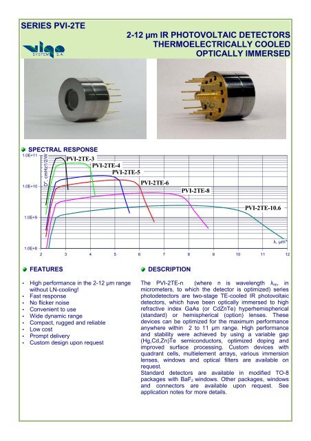
SERIES PVI-2TE 2-12 µm IR PHOTOVOLTAIC DETECTORS ...
SERIES PVI-2TE 2-12 µm IR PHOTOVOLTAIC DETECTORS ...
SERIES PVI-2TE 2-12 µm IR PHOTOVOLTAIC DETECTORS ...

You also want an ePaper? Increase the reach of your titles
YUMPU automatically turns print PDFs into web optimized ePapers that Google loves.
SPECIFICATION @ 20ºCCHARACTERISTICS* UNITS <strong>PVI</strong>-<strong>2TE</strong>-3 <strong>PVI</strong>-<strong>2TE</strong>-4 <strong>PVI</strong>-<strong>2TE</strong>-5 <strong>PVI</strong>-<strong>2TE</strong>-6 <strong>PVI</strong>-<strong>2TE</strong>-8 <strong>PVI</strong>-<strong>2TE</strong>-10.6λ op μm 3 4 5 6 8 10.6Detectivity:at λ peakat λ opcmHz 1/2 /W ≥1∙10 11≥5∙10 10 ≥6∙10 10≥3∙10 10 ≥3∙10 10≥1.5∙10 10 ≥2∙10 10≥1∙10 10 ≥6∙10 9≥3∙10 9 ≥3∙10 9≥1∙10 9Responsivity A/W ≥1 ≥1.2 ≥1.5 ≥2 ≥1 ≥0.7Response time ns ≤1 ≤20 ≤20 ≤10 ≤7 ≤3Parallel resistance-opticalarea productΩ·cm 2 ≥30 ≥13 ≥2 ≥0.30 ≥0.1 ≥0.01Optical area length × widthor diameter for round devicesmm x mmmm0.1×0.1; 0.25×0.25; 0.5×0.5; 1×1; 2×2;ø0.1; ø0.25; ø0.5; ø1; ø2; ø3Operating temperature K 220-240Acceptance angle, F#* deg 35, 1.59* See application notes for more details.0.1×0.1; 0.25×0.25;ø0.1; ø0.25;ACCESSORIES- VPAC and VPDC preamplifiers• DC or AC• Bandwidth: 100kHz, 300kHz, 1MHz, 5MHz, 10MHz, 20MHz, 50MHz, 100MHz, 250MHz and 1GHz.- Supply units- Thermocooler controllersModel DR-1Bthe combination of the support(DRB-1) and the heat sink (DR-1)Model DR-10Bthe combination of the support (DRB-1)and the heat sink for wide-bandpreamplifiers (>50 MHz) (DR-10)STCC-04Standard Thermoelectric Cooler ControllerThe preamplifiers are designed for stable of-the-shelf operation and the best resulting performance withdedicated detectors. We offer also integrated detector/preamplifier/TE cooler packages that provide moreefficient detector/preamplifier match at high frequencies, better EMI shielding. The integrated packagescan be customized to specific applications.HEADQUARTERS3 Swietlikow Str.01-389 WarsawPOLANDtel.: +48 22 666 01 45fax: +48 22 666 01 59http://www.vigo.com.plSALES OFFICE11a Wyki Str.01-318 WarsawPOLANDtel.: +48 22 666 14 10fax: +48 22 665 21 55e-mail: info@vigo.com.plAP, 06.05.05
THE FOCAL PLANE POSITION OF THE DETECTORIS DEPENDENT ON THE DIAMETER OF THE IMMERSION LENSWHICH IN TURN IS VARIED WITH THE OPTICAL AREA OF THE DETECTORposition of external lens36°Ø66±0.18±0.111.1±0.15.75±0.1dFrØ15.2±0.05Vigo TO-8 style 2-stage TEcoolerpackageWith GaAs immersion lensF - focal length of the external optics, if anyn – index of refraction, which for GaAs is approximately 3.3; values vary with λ due to dispersionSome details and examplesOptical size of detectormm x mmL × LOPTOPT0.5x0.5andsmaller1x<strong>12</strong>x22x2 and3x3Diameter of the immersion lens 2 r , mm 1.0 1.6 2.5 3.2Distance d = r ( n− 1) / n from the base of the lens tothe apparent plane of the detector, mm1.5 2.4 3.75 4.82Physical size of detector LPHYS = LOPT/ n46x46andµm x µmsmaller92x92 184x184184x184and276x276
<strong>SERIES</strong> PVMI-<strong>2TE</strong>8-<strong>12</strong> µm <strong>IR</strong> <strong>PHOTOVOLTAIC</strong> MULTIPLE JUNCTION <strong>DETECTORS</strong>THERMOELECTRICALLY COOLEDOPTICALLY IMMERSEDSPECTRAL RESPONSE9.00E+088.00E+087.00E+08D*, cmHz1/2/W6.00E+085.00E+084.00E+083.00E+082.00E+08λ, µm1.00E+082 2.5 3 3.5 4 4.5 5 5.5 6 6.5 7 7.5 8 8.5 9 9.5 10 10.5 11 11.5 <strong>12</strong>FEATURESDESCRIPTION• High performance in the long wavelengthrange without LN-cooling• Fast response• No flicker noise• Convenient to use• Wide dynamic range• Compact, rugged and reliable• Low cost• Prompt delivery• Custom design upon requestThe PVMI-<strong>2TE</strong>-n (where n is wavelength λ op , inmicrometers, to which the detector is optimized) seriesphotodetectors are two-stage TE-cooled <strong>IR</strong> photovoltaicdetectors, which have been optically immersed to highrefractive index GaAs or CdZnTe hemispherical orhyperhemispherical lenses. These devices can beoptimized for the maximum performance for longwavelength, large area devices. High performance andstability were achieved by using a newly developedvariable gap semiconductors (HgCdZnTe), optimizedcomposition/doping profiles and improved surfaceprocessing.Standard detectors are available in modified TO-8packages with BaF 2 windows.Other packages and windows are available upon request.See application notes for more details.Custom devices with quadrant cells, multielement arrays,specialized packages, connectors, windows and opticalfilters are available on request.
SPECIFICATION @ 20ºCCHARACTERISTICS UNITS PVMI-<strong>2TE</strong>-10.6λ op µm 10.6Detectivity:at λ peakat λ opcmHz 1/2 /W ≥8∙10 8≥2∙10 8Responsivity - Width Product at λ op V·mm /W ≥2.5Response time ns ≤3Resistance* Ω 30-200Optical area length × width mm x mm 0.1×0.1; 0.25×0.25; 0.5×0.5; 1×1; 2×2;Operating temperature* K 220-240Acceptance angle, F#* deg 35, 1.59* See application notes for more details.ACCESSORIES- VPAC and VPDC preamplifiers• DC or AC• Bandwidth: 100kHz, 300kHz, 1MHz, 5MHz, 10MHz, 20MHz, 50MHz, 100MHz, 250MHz and 1GHz.- Supply units- Thermocooler controllersModel DR-1Bthe combination of the support(DRB-1) and the heat sink (DR-1)Model DR-10Bthe combination of the support (DRB-1)and the heat sink for wide-bandpreamplifiers (>50 MHz) (DR-10)STCC-04Standard Thermoelectric Cooler ControllerThe preamplifiers are designed for stable of-the-shelf operation and the best resulting performance withdedicated detectors. We offer also integrated detector/preamplifier/TE cooler packages that provide moreefficient detector/preamplifier match at high frequencies, better EMI shielding. The integrated packagescan be customized to specific applications.HEADQUARTERS3 Swietlikow Str.01-389 WarsawPOLANDtel.: +48 22 666 01 45fax: +48 22 666 01 59http://www.vigo.com.plSALES OFFICE11a Wyki Str.01-318 WarsawPOLANDtel.: +48 22 666 14 10fax: +48 22 665 21 55e-mail: info@vigo.com.plAP, 06.05.05
SPECIFICATION @ 20ºCCHARACTERISTICS* UNITS <strong>PVI</strong>-3 <strong>PVI</strong>-4 <strong>PVI</strong>-5 <strong>PVI</strong>-6 <strong>PVI</strong>-8λ op μm 3 4 5 6 8Detectivity:at λ peakat λ opcmHz 1/2 /W ≥2∙10 10≥1∙10 10 ≥4∙10 9≥2∙10 9 ≥2∙10 9≥1∙10 9 ≥8∙10 8≥4∙10 8 ≥4∙10 8≥2∙10 8Responsivity A/W ≥0.75 ≥1 ≥1.25 ≥1.5 ≥1Response time ns ≤15 ≤15 ≤15 ≤<strong>12</strong> ≤7Parallel resistance-optical areaproductΩ∙cm 2 ≥5 ≥1 ≥0.3 ≥0.1 ≥0.1Optical area length × widthor diameter for round devicesmm x mmmm0.25×0.25; 0.5×0.5; 1×1; 2×2;ø0.25; ø0.5; ø1; ø2; ø3Operating temperature K 300Acceptance angle, F# deg 35, 1.59* See application notes for detailsACCESSORIES:- VPAC and VPDC preamplifiers• DC or AC• Bandwidth: 100kHz, 300kHz, 1MHz, 5MHz, 10MHz, 20MHz, 50MHz, 100MHz, 250MHz and 1GHz.-Supply unitsStandalone preamplifier packagePreamplifier with <strong>PVI</strong> detectorThe preamplifiers are designed for stable of-the-shelf operation and the best resulting performance withdedicated detectors. We offer also integrated detector/preamplifier packages that provide more efficientdetector/preamplifier match at high frequencies, better EMI shielding. The integrated packages can becustomized to specific applications.HEADQUARTERS3 Swietlikow Str.01-389 WarsawPOLANDtel.: +48 22 666 01 45fax: +48 22 666 01 59http://www.vigo.com.plSALES OFFICE11a Wyki Str.01-318 WarsawPOLANDtel.: +48 22 666 14 10fax: +48 22 665 21 55e-mail: info@vigo.com.plAP, 06.05.05
Boston Electronics Corporation91 Boylston Street, Brookline, Massachusetts 02445 USA(800)347-5445 or (617)566-3821 fax (617)731-0935www.boselec.comboselec@world.std.comWhen do I need to use a preamp? (and other comments onsignal levels and device saturation)One of the very convenient things about Vigo MCT detectors is that many users will not require a preamplifier but can insteadgo directly into an oscilloscope for display of fast transients, usually laser pulses. When is this the case and when not? Briefly,the answer is, for a CW signal, you probably need a preamp, and for short pulses widely spaced in time, you probably do notneed a preamp.The question relates to saturation levels in the detector. We consider “saturation” to be the point at which the detector outputdeviates from linear by 20%. You might want to choose another percentage deviation from linearity, but the idea remains thesame and in fact, once saturation begins it seems to happen quickly so there will not be a large difference whether we speak of1%, 20% or 50% deviation.Saturation is most easily described NOT in terms of input optical signal but in terms of output electrical signal. For example,for the model PD-10.6-3, we expect output saturation at about 10 millivolts for a CW signal, and at about 600 millivolts for asingle short pulse. These represent the extreme cases. Since few if any users have oscilloscopes that will display a signal of 10millivolts with much deflection on the CRT, those users trying to see a CW signal will pretty much always need a preamp.However, users whose input signals are short and strong (say < 1 µsec and > 5 watts peak) should be able to dispense with theamplifier and go direct to the scope using the PD-10.6-3. A certain amount of experimentation around these levels to optimizethem should be expected.Many users in fact have input waveforms that can be considered neither CW nor “short single shot” pulses. This gets us intothe intermediate “quasi-CW” regime. There are no firm rules here, but some guidance is available from experience:• Many CO 2 lasers are called “pulsed” but are in fact better described as modulated. Duty cycle is in the range of 50%and the modulation frequency is in the kHz region. These should be considered CW sources and a preamp used.• Pulsed lasers with short pulses and duty cycles
Boston Electronics Corporation91 Boylston Street, Brookline, Massachusetts 02445 USA(800)347-5445 or (617)566-3821 fax (617)731-0935www.boselec.comboselec@boselec.comOptions for mounting and powering / controlling aVigo thermoelectrically cooled <strong>IR</strong> detector:There are two possibilities; either the user makes his own mount for the detector or he uses theVigo DR-style mount.1. Choose the Vigo DR-style “Lab Bench” mount ONLY if (A) it is not too large as-is forthe space it will be used and (B) only if operation at a fixed stable temperature isrequired.2. Choose to do it yourself if the Vigo DR-style mount does not fit the space available or ifyou need to squeeze out the highest sensitivity at any given ambient temperature(maximize delta-T) rather using than a stabilized temperature set point.Do it yourself:The sketch on the following page illustrates an acceptable self fabricated heat sink and how tomount the detector on it.If you make your own heat sink you will also need to supply your own power and controlelectronics for the thermoelectric cooler. The model PID1500 TE cooler controller fromWavelength Electronics (also available from Boston Electronics) is suitable as are other similardevices. Excellent external preamps, AC-coupled to 500 MHz and DC-coupled to 200 MHz aredescribed in a following page. Also external versions of the internal heat sink enclosed preampfrom Vigo are available as external devices and often can be delivered faster than the formerline.Use our Lab Bench Mount:Our Lab Bench Mount consists of a cylindrical heat sink on a stalk with a weighted base. Thereis room inside the heat sink for a preamplifier and we offer a full range of preamps internal to theheat sink. Or the user can use an external preamp. Finally two choices of cooler controller areoffered, one with +/-1C temperature stability (corresponding to ~2.5% stability of detectoroutput) and the other with +/-0.1C temperature stability for ~0.25% output stability.Sketches with dimensions and with details of the available preamps and controllers are attached.
Thermoelectrically-cooled detectors can be kept cooled at a constant temperature during operation. Thebuilt-in thermoelectric cooler requires a supply current much higher than the maxiumum allowable currentused for the thermistor and detector element incorporated in the same package. If the supply current forthe thermoelectric cooler is applied to the thermistor or detector element even momentarily, the thermistorand detector element may be damaged. Sufficient care must be taken when dealing with supply currents.1) HandlingThe Peltier element incorporated in thermoelectically-cooled detectors is susceptible to excessive shocks,drop impacts, and vibrations. Use sufficient care in handling this type of detector.2) Heat SinkWhen operating a TE-cooled detector, always use a heat sink. If the detector is operated without using aheat sink, the detector element temperature will rise due to poor heat dissipation. If heat dissipation isinadequate, the detector element may deteriorate due to high temperature, eventually leading topermanent damage.Always use a heat sink having the specified thermal resistance (2°C/W or less for three-stage TE-cooledMCT; 3°C/W or less for two-stage TE-cooled MCT detectors). The detector’s metal package should besecurely attached to the heat sink. Although the heat capacity required of the heat sink depends on thecurrent consumption of the Peltier element, we recommend using a heat sink with a heat capacity of 2W/°C or better. The heat sink must be capable of dissipating the heat generated by a thermoelectriccooler increasing the header temperature less than a few kelvins. In practice, the radiator plate under thedetector header should be at least 2mm thick.RECOMMENDED MOUNTINGThe detector must be firmly mounted on the heat sink. This can be done by the use of a thin layer of heatconductive epoxy. Alternately, apply silicone grease between the heat sink and the detector’s metalpackage. This improves the coupling efficiency of the heat sink and package, thus reducing the thermalresistance between them.When the detector is installed on the heat sink, be sure not to apply any excessive stress to the package.This may cause cracks or leakage in the package. Do not attach the heat sink to the cap; this may causedehermetization of the detectorBoston Electronics Corporation, 91 Boylston Street, Brookline MA 02445(800)347-5445 or (617)566-3821 * fax (617)731-0935 * boselec@boselec.com * www.boselec.com
Boston Electronics Corporation91 Boylston Street, Brookline, Massachusetts 02445 USA(800)347-5445 or (617)566-3821 fax (617)731-0935www.boselec.comboselec@boselec.comIf you choose to make your own heat sink for out TE-cooled detectors, the thermalimpedance should be < 3K/W. The PID1500 and accessory evaluation PCB make aconvenient device for power and control of the cooler.PID1500 TE Cooler ControllerQuantity 1 2-4 5-24Prices $246.00 $195.00 $167.00• Single Supply Operation: +5V to +<strong>12</strong> V• Up to 1.5 Amps.• < 0.008 ° C stability (24 hours)• Adjustable Current Limit• + 8V compliance with +<strong>12</strong>V Input• Analog input to adjust TemperatureSetpoint remotely• Supports Thermistors, IC sensors, orRTD's• Temperature Setpoint, ProportionalGain, and Current Limit are useradjustable• Remotely Enable / Disable Output• Can be Modified for Resistive HeaterControlGeneral DescriptionThe PID1500 Linear Bipolar Thermoelectric Temperature Controller provides ultra-stable, lownoise temperature control from a single output DC supply. The on-board <strong>12</strong>-turn temperature settrimpot sets the desired temperature. Single turn trimpots control the proportional gain andcurrent limit. A four-position sensor select jumper applies the proper bias current for thermistors,IC sensors or RTDs. All inputs and outputs are accessed via a single 14-pin header on the base.These pins provide easy access for DC supply input, sensor, thermoelectric or resistive heaters,external control and measurements with an external digital voltmeter. The rugged, compactdesign can be used in many environments and has a 0° C to +60° C operating range. Theintegral heatsink can be removed to mount the module to a system chassis.\\Snap105913\SHARE1\Product Literature\Vigo\Wavelength PID1500.doc 10/15/2003
Accessories for PID1500 Cooler ControllerEvaluation PCBCan be used with:• PID1500 Temperature ControllerQuantity 1 2-4 5-24Prices $100.00 $100.00 $100.00+5V/8Amp PID1500 Power SupplyCan be used with:• PID1500 Temperature ControllerQuantity 1 2-4 5-24Prices $175.00 $162.00 $151.00Cannot be used with any preamplifierdue to noise.General Description+5 V / 8 Amp Switching Power Supply (Do NOT use with preamps)Size: 5.75" (L) x 2.875" (W) x 1.625 (H)Input voltage range 100-240V\\Snap105913\SHARE1\Product Literature\Vigo\Wavelength PID1500.doc 10/15/2003
Boston Electronics Corporation91 Boylston Street, Brookline, Massachusetts 02445 USA(800)347-5445 or (617)566-3821 fax (617)731-0935www.boselec.comboselec@boselec.comSTCC-04 Series Thermoelectric Cooler ControllersThe family of modern STCC-04 controllers has been designed for temperature control andstabilization of <strong>IR</strong> detectors manufactured by VIGO System S.A. The following TE cooled detectorsare included: <strong>PVI</strong>-<strong>2TE</strong>, PV-<strong>2TE</strong>, PC-<strong>2TE</strong> and PCI-<strong>2TE</strong> mounted on heatsinks DR-1(B) or DR-10(B).The STCC-04 family is characterized not only by a very good stabilization of the detectortemperature, but also by high watt-hour efficiency, low noise level, small overall dimensions andsmall bulk. High temperature stability guarantees excellent performance of the detectorindependently of the ambient conditions.The STCC-04 family includes models for constant or adjustable working temperature of thedetector. Depending on model of the controller and detector, the temperature can be kept withinthe range 233 K (-40 °C) to 278 K (+5 °C).An optional built-in secondary power supply provides all voltages needed for VPAC- or VPDC-seriespreamplifiers integrated in model DR-1 or DR-10 heatsinks with the detector. The particularparameters of the power supply are optimized for the selected model of the preamplifier resultingin the best working conditions of the whole set.STCC-04 - PP - nT – type (model specification system)STCC-04 Product identifier-PP-n-T-typeType of built-in power supply:00 - no power supply05 - power supply ±5 V / ±250 mA<strong>12</strong> - power supply ±<strong>12</strong> V / ±<strong>12</strong>0 mA15 - power supply ±15 V / ±100 mAG1 - combined power supply (- 0.5 V, +4.5 V and +7 V) for VPAC-1000 preamplifier2 - two-stage cooler (standard)3 - three stage coolerType of thermistor:A - TB06-22B - BR14KA132J-A (only for certain types of <strong>IR</strong> detectors)Programmed temperature of <strong>IR</strong> detector:P5 - 278 K (+5 °C)30 - 243 K (-30 °C)35 - 238 K (-35 °C)40 - 233K (-40 °C)RC - precisely adjusted within the range 233 to 278 K (-40 to +5 °C)R4 - switched within the range 233 to 243 K (-40 to -30 °C)Custom-set temperatures are also available.
<strong>IR</strong> Measuring Set3.5. Heatsinks for TE-Cooled DetectorsTE-cooled detectors are distributed in TO-8 packages. The package, whichalso includes TE-cooler, should be mounted on a suitable heatsink. TheDR-1 heatsink developed and offered by our company provides optimaldetector cooling and stabilization of its temperature. The heatsink playsalso a role of the preamplifier’s housing. Such construction provides asignificant improving of screening and reducing influence of external noiseson the performance of the detection system. The DR-1 can be easilyattached to all typical blocks of optical measuring systems. The DR-10 typeof increased length has been designed for preamplifiers of bandwidth50MHz – 250 MHz. When equipped with DRB-1 stand, the detecting unitcan be used on any flat surface and its vertical position can be easilyadjusted. The complete unit incorporating DR-1 or DR-10 heatsink andDRB-1 stand is marked as DR-1B or DR-10B set respectively.Heatsinks dedicated for detectors manufactured by VIGO System S.A.Type of DetectorVPxx- 01iVPxx- 03iVPxx- 1iVPxx- 5iVPxx- 10iVPxx- 20iVPxx- 50iVPxx- 100iVPxx- 250iType of HeatsinkDR-1BDR-1BDR-1BDR-1BDR-1BDR-1BDR-10BDR-10BDR-10BP
<strong>IR</strong> Measuring SetFig.7. Detector in DR-1 Housingon DRB-1 StandFig.9DR-1BUnit(frontview)PFig.8. DRB-1 StandFig.10DR-1B Unit (rear view)<strong>IR</strong> Measuring SetFig.11. Detector in DR-10 Housing)Fig.13Detector in DR-1 Housing(Front View)PFig.<strong>12</strong>. DRB-1 StandFig.14Detector in DR-1 Housing(Rear View)
<strong>IR</strong> Measuring SetFig.15. Dimensions of DR-1B HousingP<strong>IR</strong> Measuring SetFig.16. Dimensions of DR-10B HousingP
<strong>IR</strong> Measuring SetFig.17 Pin Assignment of 9-pin Canon for DR-1 & DR-10 HousingP<strong>IR</strong> Measuring Set3.6. DR-1 Housing. Examples of ApplicationFig.18. Preamplifier and Detector integrated inside DR-1 Housing mountedon DRB-1 StandFig.19. Preamplifier and Detector in DR-1B Housing mounted on OpticalBenchP
<strong>IR</strong> Measuring Set4. VPAC and VPDC PreamplifiersVPAC-xx and VPDC-xx preamplifiers take full advantage of all detectors’parameters and provide the best protection against ESD, EMI and humanmistakes. The input stages of all VPAC-xx and VPDC-xx preamplifiershave been built with application of ultra low noise transistors or integratedcircuits. They have been optimally configured and biased to achievemaximal S/N ratio, keeping the remaining parameters (gain, bandwidth,maximal output signal and others) within the required limits.4.1. Noise in AmplifiersTo amplify a small signal deriving from <strong>IR</strong> detector to the value allowing itsfurther processing, a multi-stage preamplifier is usually needed. A resultantnoise performance of the amplifier (preamplifier) depends in practice on thenoise performance of the first stage. The noise performance is usuallyexpressed as the noise voltage or noise current referred to its input (forvoltage or current mode amps respectively). Input stages of VPAC-xx -VPDC-xx series have been designed towards achieving maximal s/n ratiofor a specific type of detector, taking full advantage of its performance.4.2. Technical DataVPAC-xx series presents AC preamplifiers designed for use withphotovoltaic and photoconductive detectors. VPDC-xx series – DCpreamplifiers cope with photovoltaic detectors. Depending on what type of<strong>IR</strong> detector is to be used, we offer specific version of a suitablepreamplifier:VPAC-xx-i and VPDC-xx-i preamplifiers are mounted inside DR-1 orDR-10 heatsink and designated for use with TE-cooled detectors. In thiscase a measuring set must be equipped with STCC or CTTC controller ofthe TE cooler. Building the preamplifier into the heatsink enabled radicalshortening the connections between the detector and the input stage whatresulted in significant lowering of EMI level.The output signal of the preamplifier is available on BNC connector but theremaining signals (supply voltages and driving signals for the TE-cooler’scontroller) come out via 9-pin Canon connectorFor some applications VPAC-xx-s and VPDC-xx-s standing alonepreamplifiers are useful. They are supplied in screened housings equippedP
<strong>IR</strong> Measuring Setwith BNC connectors for the input and output signals and 9-pin Canonconnectors for the power supply.All preamplifiers require supplying devices of very low noise level at theoutput (like accumulators or especially designed well-filtered powersupplies). For standing alone preamplifiers our PPS Ultra Low NoisePower Supply is recommended.P
<strong>IR</strong> Measuring SetTable 4. Technical Specification of VPAC and VPDC PreamplifiersVPACSeriesBandwidthLow Freq.High Freq.VPAC-0110Hz100 kHzVPAC-03VPAC-1VPAC-5VPAC-10VPAC-20VPAC-50VPAC-10010Hz 10Hz 10Hz 10Hz 10Hz 1 kHz 1 kHz300 kHz 1 MHz 5 MHz 10 MHz 20 MHz 50 MHz 100MHzVPAC-2501 kHz250MHzTrans-imp.[kŸ@Outputvoltage[V pp ]Inputnoisecurrent[pA/Hz 1/2 ]PowersupplyOutputimpedanceVPDCSeries100 100 100 24 10 5 4 2 514 14 10 4 4 4 3 3 1I n =<strong>12</strong>00/R dR d – detector’s resistancein ŸVPDC-01I n =3000/R d I n =2000/R d I n =3000/R d± 15V/25mA ± 15V/40mA ± <strong>12</strong>V/40mAVPDC-03VPDC-1VPDC-550ΩVPDC-10VPDC-20VPDC-50VPDC-100± <strong>12</strong>V/60mAVPDC-250Bandwidth 0 -100KHz0 -300KHz0 - 1MHz0 - 5MHz0 - 10MHz0 - 20MHz0 - 50MHz0 - 100MHz0 - 250MHzWhen the specified above parameters do not meet your requirements,get in touch with us please.P
<strong>IR</strong> Measuring Set4.2.1. Appearance and DimensionsFig.21. Standing Alone Preamplifier ofVPxC-xx-s SeriesFig.22.Standing Alone Preamplifier ofVPxC-xx-s Series with R005 DetectorFig.23. Dimensions of Standing Alone HousingP
VPAC 1000WIDE BANDWIDTH CURRENT PREAMPLIFIERFEATURESLow noise and wide bandwidth transimpedancepreamplifier (10kHz to 1 GHz, in dependence ondetector capacitance). The devices enforces DCbias that is required for optimized operation of agiven type of infrared detector. Integrated withdetectors packages are available.SPECIFICATIONPARAMETERBandwidth (-3dB)TransimpedanceOutputInput noise densityVALUE10kHz- 1000MHz @50Ω, C det ≤1pF7,5*10 3 V/A± 0,8 V @ R L=50Ω≤ 5,9pA @ R det =2kΩ||3pF f o=10kHzOutput impedance50ΩSupply voltage From dedicated power supply *Supply current+55 mA -20 mA* for cooled detectors preamplifier is supplied from power supply built in thermoelectric cooler controller model STCC-04for uncooled detectors preamplifier is supplied from dedicated power supply model PPSPERFORMANCE CHARACTERISTICS** performance measured at R det =1kΩ||3pF
DIMENSIONSThe detector is followed by the high performance dedicated preamplifier specially designed to obtain thebest performance from the VIGO System's detector. Each preamplifier is carefully optimized to work withparticular type of detector. The preamplifier ensures stable work in all conditions and the highest signal tonoise ratio of the whole system. Application of the completely new housings integrated with heatsinkresults in effective cooling of the detector, provides effective EMI shielding and is more convenient for thecustomer (easy fastening to other equipment).See also our offer on preamplifiers: CLDC, CLAC series and STCC-04 thermocooler controller.HEADQUARTERS3 Swietlikow Str.01-389 WarsawPOLANDSALES OFFICE11a Wyki Str.01-318 WarsawPOLANDtel.: +48 22 666 01 45fax: +48 22 666 01 59http://www.vigo.com.pltel.: +48 22 666 14 10fax: +48 22 665 21 55e-mail: info@vigo.com.pl
VIGO System S.A.Application NotesPackages, Windows and Pin LayoutIntroductionDevices are typically delivered in five types of packages:TO-8, BNC-based, TO-39, PEM with SMA connector andquadrant with SMA connectors .The BNC and the TO-39 packages are used for uncooledPV and PC devices. The TO-8 package is used for TE cooleddevices. All TE-cooled and PEM detectors are provided witha window. We offer windows optimized for different spectralbands: BaF 2, ZnSe, CdTe, CaF 2, sapphire, AR-coated Si andAR-coated Ge.TO-8 PackagesDescriptionThe TO-8-based packages are used for thermoelectricallycooled devices (PC-<strong>2TE</strong>, PCI-<strong>2TE</strong>, PV-<strong>2TE</strong> and <strong>PVI</strong>-<strong>2TE</strong>).The packages are backfilled with inert heavy gases of thelow thermal conductivity (Kr/Xe mixtures). Water vapourcondensation is prevented by careful package sealing andwater absorbers.BaF 2 windows are used as a standard.Dimensions in millimetershttp://www.vigo.com.plinfo@vigo.com.pl
VIGO System S.A.Packages with BNC ConnectorsDescriptionThe specialized BNC-based packages are used foruncooled room temperature devices (R005, MPC, PC, PCI,PV, <strong>PVI</strong>).Standard devices are delivered without a window.Dimensions in millimeters.TO-39-Style PackagesDescription:The TO-39-based packages are used for uncooled roomtemperature devices (R005, MPC, PC, PCI, PV, <strong>PVI</strong>).Standard devices are delivered without a window.Dimensions in millimeters 13 4-6Detector3.227.75.089.2Detector8.41.9http://www.vigo.com.plinfo@vigo.com.pl
VIGO System S.A.PEM Specialized PackagesDescriptionThe photoelectromagnetic detectors (PEMI-L, PEM-L) aretypically mounted in the specialized packages with SMAconnectors, designed for broadband applications. A magneticcircuit is incorporated into the package.The 10.6 µm AR-coated germanium window is supplied asa standard.Dimensions in millimetersQuadrant PackagesDescriptionDevices are typically mounted in specially designedpackages, supplied with the SMA connectors, suitable forwide band applications. Those packages are used in PCQLdevices.Standard devices are delivered without a window.Dimensions in millimetersDetectorActiveElementsSMAConnector 6.0+0.30- 0.00 13 245.51023403030 16 +0.00- 0.1013 + 0.00- 0.102025344060http://www.vigo.com.plinfo@vigo.com.pl
VIGO System S.A.Custom EngineeringVIGO System S.A is highly responsible engineering drivencompany. 25 years of experience have given us opportunityto provide the most sophisticated and extensive CustomEngineering capabilities in the field of infrared technology.We have realized that the most of the <strong>IR</strong> systems need someunique features of devices. We treat every customer as apartner and we offer solutions according to partner's needs.At any stage of the development process our CustomEngineering staff is ready for cooperation.To help our valuable customers we use sophisticatedepitaxial techniques, advanced material processing andmicrooptic systems. Our engineers are experts in designingand manufacturing a custom <strong>IR</strong> system, from a epitaxial layerto ultrawide bandwidth electronics. Our service mightsignificantly shorten the initial phase of the customer productdevelopment.Our expertise is regularly called upon by our customers forspecialized devices for OEM product development and forengineering prototype development.Our offer includes state-of-art uncooled devices:– PC, PV and PEM detectors optimised for any wavelengthwithin 1.5÷16µm range– Narrow and wide bandwidth devices– Multicolor devicesQuadrant Detector in a Custom PackageCustom packages and various detector formats areavailable upon request.Custom detector formats include:– Specially shaped single element detectors– Linear and bilinear arrays– Small 2-D arrays (e.g. quadrants)Upon request, the custom detectors are integrated withsupporting electronics:– Preamplifiers– TE-coolers– Coolers controllers– Temperature sensorsWe can provide any preamplifiers up to 1 GHzbandwidth.Standard PackagesVIGO System S.A staff is ready for any kind ofcooperation with production departments, R&D and scientificgroups all around the world.Multielement Linear ArrayNew Epitaxial Production Systemhttp://www.vigo.com.plinfo@vigo.com.pl
VIGO System S.A.TE coolingCooling reduces noise, increases responsivity and in somedevices improves high frequency response.The devices with two stage TE coolers (T op=230K) areavailable as a standard. Three and four stage coolers(T op=210K for 3TE, T op=190K for 4TE) are available uponrequest.Thermoelectric CoolerTE cooler (TEC) is biased with the DC power. The coolersare characterized by:Optimum current: I optCurrent resulting the highest temperature difference at thespecified conditions.Maximum current: I maxThe maximal permissible value. The higher currents maydamage the cooler. To ensure lasting operation it isrecommended to supply the cooler with
VIGO System S.A.Mechanical AccessoriesDR-10B Set: Base (DRB-1) and Heat Sink (DR-10) forWide-Band Preamplifiers (>50 Mhz)Beam Power LimitationsFor devices without immersion lenses continuous workincident beam power must not exceed 100 W/cm 3 and pulsesshorter then 1 µs must not exceed 1 MW/cm 3 .For optically immersed devices continuous work incidentbeam power must not exceed 20 W/cm 3 and pulses shorterthen 1 µs must not exceed 10 kW/cm 3 .Saturation power density depend on a type of the detectorand can be provided upon request.Shaping LeadsAvoid bending the leads at a distance less then 2 mm froma base of the package not to damage the glass seals. Whenshaping the leads, do not exceed the following limits:– Maximal mechanical tension – 0.5 kg for 5 sec– Maximum two right angle bends and three twists at thedistance minimum 6 mm from the base of the packageWhen shaping the leads of the detector, short the leads ofthe detecting element with a special jumper.Soldering Leads<strong>IR</strong> Detectors can be easily damaged by excessive heat.Special care should be taken when soldering the leads. Usageof heat sinks is highly recommended. Tweezers can be usedfor this purpose; clamp a lead being soldered at a placebetween the soldering iron and the base of the case. To avoiddestructive influence of ESD and other accidental voltages(deriving for example from a non-grounded soldering iron)(e.g. on <strong>PVI</strong>-<strong>2TE</strong> detectors) all rules for handling LSIintegrated circuits should be applied to <strong>IR</strong> detectors too.DR-1B Set: Base (DRB-1) and Heat Sink (DR-1)Precautions for Use, WarrantyStorageThe following conditions should be fulfilled for the safeand reliable operation of detectors:– Storage temperature: -10ºC ÷ +50ºC– Avoiding ESD; detectors are very sensitive toelectrostatic discharges, therefore they should be storedhaving detection element’s leads shorted by a specialjumper.HandlingWindows of some detectors are made of very soft materialslike ZnSe or BaF 2. Particular attention should be paid to notscratch a surface of the window when some sharp tools arebeing used. A damaged window may entirely degrade thedetector’s performance. Excessive mechanical stress appliedto the package itself or to a device containing the package,may result in permanent damage of the latter.Cleaning WindowKeep the window clean. Use a soft cotton cloth dampedwith isopropyl alcohol and wipe off the surface gently ifnecessary.Mechanical ShocksThe Peltier elements may be damaged by the excessivemechanical shocks and vibrations. Great care isrecommended during all manipulations (including normalexploitation) to avoid the mentioned hazards. Drop impactsagainst a hard base may be particularly dangerous.Heat SinkingThe base of the package must be firmly attached to theheatsink. This can be achieved either by using a thin layer(
oselec@boselec.com Boston Electronics Corporation www.boselec.comDC to 10 MHz Bandwidth, 2 to 11 m LAB Bench DetectorHEADQUARTERSZLHWOLNRZ6WU-389 WarsawSALES OFFICE11a Wyki Str., 01-318 Warsawtel.: +48 22 666 01 45 tel.: +48 22 666 14 06, 666 14 10fax: +48 22 666 01 59 fax: +48 22 665 21 55http://www.vigo.com.ple-mail: info@vigo.com.pl
Preamps: achieve detector-noise-limited performancePreamps: achieve detector-noise-limited performanceDC-Coupled Preamps for Photovoltaic HgCdZnTe DetectorsModel 481-1 481-5 481-10 481-20 481-50 481-100 481-200 477AGgain stageGain [RD is detectorresistance]Transimpedance Factor(Vout/Iin)100 K/ RD 24 K/ RD 10 K/ RD 5 K/ RD 4 K/ RD 2 K/ RD 1 K/ RD VariableX5 to 200491 VideoLine Driver100K 24 K 10 K 5 K 4 K 2 K 1 K Input 10K --Bandwidth (DC to…) Price $795 $795 $5951 MHz 5 MHz 10 MHz 20 MHz 50 MHz 100 MHz 200 MHz 10 + MHz 100 MHzOutput (volts, max, p-p) 5 1 5 4Noise (n V/Hz1/2) 1.0 1.8 --Input (Volts @ milliAmps+/-<strong>12</strong> to 15 @ 18 +/-6 @ 25 +/- 5 to +/- <strong>12</strong> @ 20quiescent)Size (inches) 2 x 2 x 1 1.1 x 0.9 x 2.3X2AC-Coupled Preamps for Photovoltaic or Photoconductive HgCdZnTe DetectorsModel 050/50 060/40 070/40 080/34 480 490 493A 493A/40 477AGgain stageGain 50 dB 40 dB 40 dB 34 dB 32 dB 26 dB 20 dB 40 dB Variable,X5 to 200491 VideoLine DriverBandwidth from: 10 Hz 1KHz - --To: 1 MHz 3MHz 10 MHz 20 MHz 50 MHz 100 MHz 500+ MHz 500 10 + MHz 100 MHzMHzOutput (volts, max, p-p) 4 3 5 5 5Noise figure 1dB nominal 2.8 dB nominal 50 µV RMS,widebandInput (Volts @ milliAmpsPrice $795 $895 $795 $595-<strong>12</strong> @ 10 to 20 +/-<strong>12</strong> to 15 @ 40 +6 to 8 @ 30 +/-5 to +/-<strong>12</strong> @ 20quiescent)Size (inches) 2 x 2 x 1 1.1 x 0.9 x 2.3--X2Notes:1. We can tailor preamp bandwidth to customer requirements.2. All units have BNC Connectors on Input and Output.3. Output impedance is 50 ohms for all except model 491 which may be 2ohm or 75 ohm output instead of 50 ohm on special order.4. Cable from detector to amplifier should be less than 3 feet.5. Use model 477AG gain stage on amp output if extra output voltageneeded.6. Use the model 491 line driver when output cable is longer than 6 feet.7. Operating temperature range -55 to +85 C8. Prices current as of 6 July 2004. Specifications & prices subject tochange without notice.Boston Electronics Corporation, 91 Boylston Street, Brookline MA 02445(800)347-5445 or (617)566-3821 * fax (617)731-0935 * boselec@boselec.com * www.boselec.com