instruction manual for inline refractometer pr-03 - K-Patents
instruction manual for inline refractometer pr-03 - K-Patents
instruction manual for inline refractometer pr-03 - K-Patents

Create successful ePaper yourself
Turn your PDF publications into a flip-book with our unique Google optimized e-Paper software.
Protected by one or more of<br />
the following U.S. patents:<br />
Patent No. 4,571,075<br />
Patent No. 5,563,737<br />
Patent No. 5,009,113<br />
Patent No. 5,617,201<br />
Patent No. 5,309,288<br />
Patent No. 6,067,151<br />
INSTRUCTION MANUAL<br />
FOR INLINE REFRACTOMETER<br />
PR-<strong>03</strong><br />
WARNING<br />
The <strong>pr</strong>ocess medium may be hot or otherwise hazardous.<br />
Precautions when removing the sensor from the <strong>pr</strong>ocess line:<br />
Make positively sure that the <strong>pr</strong>ocess line is not under <strong>pr</strong>essure. Open a vent valve to the atmosphere.<br />
For a <strong>pr</strong>ism wash system, close a hand valve <strong>for</strong> the wash medium and disable the wash valve.<br />
Loosen the clamp cautiously, be <strong>pr</strong>epared to tighten again.<br />
Be out of the way of any possible splash and ensure the possibility of escape.<br />
Use shields and <strong>pr</strong>otective clothing adequate <strong>for</strong> the <strong>pr</strong>ocess medium.<br />
Do not rely on avoidance of contact with the <strong>pr</strong>ocess medium.<br />
After removal of the sensor, it may be necessary to mount a blind cover <strong>for</strong> security reasons.<br />
Document/Revision No. INM-3: Rev. 2/4 Effective: February 15 th , 2005<br />
This <strong>pr</strong>oduct <strong>manual</strong> is delivered to the end user with a K-<strong>Patents</strong> <strong>pr</strong>oduct.<br />
In<strong>for</strong>mation in this <strong>manual</strong> is subject to change without notice. When the <strong>manual</strong> is changed,<br />
a revised copy is made available at http://www.kpatents.com/.<br />
Feedback on this <strong>manual</strong> can be sent by email to <strong>manual</strong>s@kpatents.com.<br />
THE PASSWORD FOR PR-<strong>03</strong> IS 7 8 4 5 1 2 IN PROGRAM VERSIONS 4.0 AND HIGHER.<br />
K-PATENTS OY<br />
Postal address:<br />
P.O. Box 77<br />
FIN-01511 Vantaa, Finland<br />
Tel. + 358-9-825 6640<br />
Fax +358-9-8256 6461<br />
info@kpatents.com<br />
www.kpatents.com<br />
K-PATENTS OY<br />
Street address:<br />
Elannontie 5<br />
FIN-01510 Vantaa, Finland<br />
K-PATENTS, INC.<br />
1804 Centre Point Circle,<br />
Suite 106,<br />
Naperville, IL 60563<br />
Tel. +1-630-955 1545<br />
Fax +1-630-955 1585<br />
Info@kpatents-usa.com<br />
www.kpatents.com
Table of contents<br />
1 Introduction . . . . . . . . . . . . . . . . . . . . . . . . . . . . . . . . . . . . . . . . . . . . . . . . . . . . . . . . . . . . . . . . . . 1<br />
1.1 PR-<strong>03</strong> <strong>refractometer</strong> models . . . . . . . . . . . . . . . . . . . . . . . . . . . . . . . . . . . . . . . . . . . . . . . 1<br />
1.2 Principle of measurement . . . . . . . . . . . . . . . . . . . . . . . . . . . . . . . . . . . . . . . . . . . . . . . . . . 2<br />
1.3 General safety considerations . . . . . . . . . . . . . . . . . . . . . . . . . . . . . . . . . . . . . . . . . . . . . . 3<br />
1.4 Warranty . . . . . . . . . . . . . . . . . . . . . . . . . . . . . . . . . . . . . . . . . . . . . . . . . . . . . . . . . . . . . . . 3<br />
1.5 Disposal . . . . . . . . . . . . . . . . . . . . . . . . . . . . . . . . . . . . . . . . . . . . . . . . . . . . . . . . . . . . . . . . 3<br />
2 Inline <strong>refractometer</strong> sensor . . . . . . . . . . . . . . . . . . . . . . . . . . . . . . . . . . . . . . . . . . . . . . . . . . . . 5<br />
2.1 Sensor description . . . . . . . . . . . . . . . . . . . . . . . . . . . . . . . . . . . . . . . . . . . . . . . . . . . . . . . . 5<br />
2.2 Mounting the sensor . . . . . . . . . . . . . . . . . . . . . . . . . . . . . . . . . . . . . . . . . . . . . . . . . . . . . . 6<br />
2.2.1 Choosing sensor mounting location . . . . . . . . . . . . . . . . . . . . . . . . . . . . . . . . . . . . . . . . . 6<br />
2.2.2 Check list <strong>for</strong> pipe mounting (PR-<strong>03</strong>-A, PR-<strong>03</strong>-D, PR-<strong>03</strong>-M) . . . . . . . . . . . . . . . . . . . . . 7<br />
2.2.3 Check list <strong>for</strong> mounting in a tank, a vessel or a large pipe (PR-<strong>03</strong>-P) . . . . . . . . . . . . . . . 8<br />
3 Indicating transmitter (IT-R) . . . . . . . . . . . . . . . . . . . . . . . . . . . . . . . . . . . . . . . . . . . . . . . . . . . 9<br />
3.1 Indicating transmitter description . . . . . . . . . . . . . . . . . . . . . . . . . . . . . . . . . . . . . . . . . . 9<br />
3.2 Mounting Indicating transmitter . . . . . . . . . . . . . . . . . . . . . . . . . . . . . . . . . . . . . . . . . . . 10<br />
3.2.1 Mounting the Interconnecting cable . . . . . . . . . . . . . . . . . . . . . . . . . . . . . . . . . . . . . . . . 10<br />
3.2.2 Electrical connections . . . . . . . . . . . . . . . . . . . . . . . . . . . . . . . . . . . . . . . . . . . . . . . . . . . 11<br />
3.2.2.1 Connecting with sensor . . . . . . . . . . . . . . . . . . . . . . . . . . . . . . . . . . . . . . . . . . . . . . . . 12<br />
3.2.2.2 AC power connection . . . . . . . . . . . . . . . . . . . . . . . . . . . . . . . . . . . . . . . . . . . . . . . . . 12<br />
3.2.2.3 +24 V DC power connection . . . . . . . . . . . . . . . . . . . . . . . . . . . . . . . . . . . . . . . . . . . . 12<br />
3.2.2.4 Current output connection . . . . . . . . . . . . . . . . . . . . . . . . . . . . . . . . . . . . . . . . . . . . . 13<br />
3.2.2.5 Serial bus connections . . . . . . . . . . . . . . . . . . . . . . . . . . . . . . . . . . . . . . . . . . . . . . . . 13<br />
3.2.2.6 Input switch connections . . . . . . . . . . . . . . . . . . . . . . . . . . . . . . . . . . . . . . . . . . . . . . . 13<br />
3.2.3 Serial output connections: connecting a computer with the IT-R . . . . . . . . . . . . . . . . . 14<br />
3.2.4 Demo mode connection . . . . . . . . . . . . . . . . . . . . . . . . . . . . . . . . . . . . . . . . . . . . . . . . . 15<br />
3.3 Cable signals between IT-R and sensor . . . . . . . . . . . . . . . . . . . . . . . . . . . . . . . . . . . . . . 16<br />
4 Accessory units . . . . . . . . . . . . . . . . . . . . . . . . . . . . . . . . . . . . . . . . . . . . . . . . . . . . . . . . . . . . . 17<br />
4.1 Separate relay units . . . . . . . . . . . . . . . . . . . . . . . . . . . . . . . . . . . . . . . . . . . . . . . . . . . . . . 17<br />
4.1.1 Relay unit description . . . . . . . . . . . . . . . . . . . . . . . . . . . . . . . . . . . . . . . . . . . . . . . . . . . 17<br />
4.1.1.1 Relay unit PR-7080 . . . . . . . . . . . . . . . . . . . . . . . . . . . . . . . . . . . . . . . . . . . . . . . . . . . 18<br />
4.1.1.2 Relay unit -WR . . . . . . . . . . . . . . . . . . . . . . . . . . . . . . . . . . . . . . . . . . . . . . . . . . . . . . 18<br />
4.1.2 Prism wash system description . . . . . . . . . . . . . . . . . . . . . . . . . . . . . . . . . . . . . . . . . . . . 18<br />
4.1.3 Relay unit mounting and connections . . . . . . . . . . . . . . . . . . . . . . . . . . . . . . . . . . . . . . . 18<br />
4.1.3.1 Mounting and connecting Relay unit PR-7080 . . . . . . . . . . . . . . . . . . . . . . . . . . . . . . 18<br />
4.1.3.2 Mounting and connecting Relay unit -WR . . . . . . . . . . . . . . . . . . . . . . . . . . . . . . . . . 20<br />
4.1.4 Mounting and connecting <strong>pr</strong>ism wash systems . . . . . . . . . . . . . . . . . . . . . . . . . . . . . . . . 20<br />
4.1.4.1 Recommended wash <strong>pr</strong>essures and times . . . . . . . . . . . . . . . . . . . . . . . . . . . . . . . . . . 20<br />
4.1.4.2 Prism wash nozzles . . . . . . . . . . . . . . . . . . . . . . . . . . . . . . . . . . . . . . . . . . . . . . . . . . . 20<br />
4.1.4.3 Mounting of <strong>pr</strong>ism wash systems with steam and water . . . . . . . . . . . . . . . . . . . . . . . 23<br />
4.1.4.4 Mounting of <strong>pr</strong>ism wash systems with high <strong>pr</strong>essure water . . . . . . . . . . . . . . . . . . . . 25<br />
4.2 External output unit PR-7090 . . . . . . . . . . . . . . . . . . . . . . . . . . . . . . . . . . . . . . . . . . . . . 26<br />
4.2.1 Description . . . . . . . . . . . . . . . . . . . . . . . . . . . . . . . . . . . . . . . . . . . . . . . . . . . . . . . . . . . 26<br />
4.2.2 External output unit mounting and connections . . . . . . . . . . . . . . . . . . . . . . . . . . . . . . . 26
5 Startup, configuration and calibration adjustment . . . . . . . . . . . . . . . . . . . . . . . . . . . . . . 29<br />
5.1 Startup . . . . . . . . . . . . . . . . . . . . . . . . . . . . . . . . . . . . . . . . . . . . . . . . . . . . . . . . . . . . . . . . 29<br />
5.2 System check . . . . . . . . . . . . . . . . . . . . . . . . . . . . . . . . . . . . . . . . . . . . . . . . . . . . . . . . . . . 29<br />
5.2.1 Checking accessory units . . . . . . . . . . . . . . . . . . . . . . . . . . . . . . . . . . . . . . . . . . . . . . . . 30<br />
5.2.2 Testing <strong>pr</strong>ism wash . . . . . . . . . . . . . . . . . . . . . . . . . . . . . . . . . . . . . . . . . . . . . . . . . . . . . 30<br />
5.3 Using Indicating transmitter . . . . . . . . . . . . . . . . . . . . . . . . . . . . . . . . . . . . . . . . . . . . . . 31<br />
5.3.1 Keyboard functions . . . . . . . . . . . . . . . . . . . . . . . . . . . . . . . . . . . . . . . . . . . . . . . . . . . . . 31<br />
5.4 Soft key Display: Getting in<strong>for</strong>mation on the <strong>pr</strong>ocess<br />
and the settings . . . . . . . . . . . . . . . . . . . . . . . . . . . . . . . . . . . . . . . . . . . . . . . . . . . . . . . . . 32<br />
5.4.1 Viewing the Optical image . . . . . . . . . . . . . . . . . . . . . . . . . . . . . . . . . . . . . . . . . . . . . . . 33<br />
5.4.2 Viewing System configuration . . . . . . . . . . . . . . . . . . . . . . . . . . . . . . . . . . . . . . . . . . . . 33<br />
5.4.3 Checking conditions inside sensor head . . . . . . . . . . . . . . . . . . . . . . . . . . . . . . . . . . . . . 33<br />
5.5 Soft key Calibrate: Viewing and changing system settings . . . . . . . . . . . . . . . . . . . 34<br />
5.5.1 Viewing Optical image and raw data . . . . . . . . . . . . . . . . . . . . . . . . . . . . . . . . . . . . . . . 34<br />
5.5.2 Raw data explanations . . . . . . . . . . . . . . . . . . . . . . . . . . . . . . . . . . . . . . . . . . . . . . . . . . . 34<br />
5.5.3 Viewing Scaled image . . . . . . . . . . . . . . . . . . . . . . . . . . . . . . . . . . . . . . . . . . . . . . . . . . . 35<br />
5.5.4 Viewing slope . . . . . . . . . . . . . . . . . . . . . . . . . . . . . . . . . . . . . . . . . . . . . . . . . . . . . . . . . 35<br />
5.5.5 Viewing Image diagnostics . . . . . . . . . . . . . . . . . . . . . . . . . . . . . . . . . . . . . . . . . . . . . . . 36<br />
5.6 Configuring input switches . . . . . . . . . . . . . . . . . . . . . . . . . . . . . . . . . . . . . . . . . . . . . . . . 36<br />
5.7 Configuring relays . . . . . . . . . . . . . . . . . . . . . . . . . . . . . . . . . . . . . . . . . . . . . . . . . . . . . . . 37<br />
5.8 Configuring external output unit . . . . . . . . . . . . . . . . . . . . . . . . . . . . . . . . . . . . . . . . . . . 39<br />
5.9 Configuring automatic <strong>pr</strong>ism wash . . . . . . . . . . . . . . . . . . . . . . . . . . . . . . . . . . . . . . . . . 39<br />
5.9.1 Timed wash . . . . . . . . . . . . . . . . . . . . . . . . . . . . . . . . . . . . . . . . . . . . . . . . . . . . . . . . . . . 40<br />
5.9.2 Smart wash . . . . . . . . . . . . . . . . . . . . . . . . . . . . . . . . . . . . . . . . . . . . . . . . . . . . . . . . . . . 40<br />
5.9.3 Preventing automatic wash . . . . . . . . . . . . . . . . . . . . . . . . . . . . . . . . . . . . . . . . . . . . . . . 41<br />
5.9.4 Prism wash check . . . . . . . . . . . . . . . . . . . . . . . . . . . . . . . . . . . . . . . . . . . . . . . . . . . . . . 41<br />
5.10 Adjusting concentration calibration . . . . . . . . . . . . . . . . . . . . . . . . . . . . . . . . . . . . . . . . 43<br />
5.10.1 Checking current calibration . . . . . . . . . . . . . . . . . . . . . . . . . . . . . . . . . . . . . . . . . . . . . . 43<br />
5.10.2 Concentration calibration from keyboard . . . . . . . . . . . . . . . . . . . . . . . . . . . . . . . . . . . . 43<br />
5.10.3 Output current range selection . . . . . . . . . . . . . . . . . . . . . . . . . . . . . . . . . . . . . . . . . . . . 44<br />
5.10.4 Temperature calibration . . . . . . . . . . . . . . . . . . . . . . . . . . . . . . . . . . . . . . . . . . . . . . . . . 44<br />
5.10.5 Adjusting damping time . . . . . . . . . . . . . . . . . . . . . . . . . . . . . . . . . . . . . . . . . . . . . . . . . 44<br />
5.10.6 Field calibration . . . . . . . . . . . . . . . . . . . . . . . . . . . . . . . . . . . . . . . . . . . . . . . . . . . . . . . 45<br />
5.10.7 Bench calibration . . . . . . . . . . . . . . . . . . . . . . . . . . . . . . . . . . . . . . . . . . . . . . . . . . . . . . 46<br />
6 Regular maintenance . . . . . . . . . . . . . . . . . . . . . . . . . . . . . . . . . . . . . . . . . . . . . . . . . . . . . . . . 47<br />
6.1 Checking the sensor moisture . . . . . . . . . . . . . . . . . . . . . . . . . . . . . . . . . . . . . . . . . . . . . 47<br />
6.2 Checking and replacing <strong>pr</strong>ism or <strong>pr</strong>ism gaskets . . . . . . . . . . . . . . . . . . . . . . . . . . . . . . 47<br />
6.3 Disassembling and assembling a standard length sensor . . . . . . . . . . . . . . . . . . . . . . . 48<br />
6.3.1 Disassembling the sensor . . . . . . . . . . . . . . . . . . . . . . . . . . . . . . . . . . . . . . . . . . . . . . . . 48<br />
6.3.2 Replacing the <strong>pr</strong>ism and <strong>pr</strong>ism gaskets . . . . . . . . . . . . . . . . . . . . . . . . . . . . . . . . . . . . . . 49<br />
6.3.3 Assembling the sensor . . . . . . . . . . . . . . . . . . . . . . . . . . . . . . . . . . . . . . . . . . . . . . . . . . 50<br />
6.4 Disassembling and assembling a <strong>pr</strong>obe sensor . . . . . . . . . . . . . . . . . . . . . . . . . . . . . . . . 51<br />
6.4.1 Disassembling the <strong>pr</strong>obe sensor . . . . . . . . . . . . . . . . . . . . . . . . . . . . . . . . . . . . . . . . . . . 51<br />
6.4.2 Replacing the <strong>pr</strong>ism and <strong>pr</strong>ism gaskets . . . . . . . . . . . . . . . . . . . . . . . . . . . . . . . . . . . . . . 52<br />
6.4.3 Assembling the <strong>pr</strong>obe sensor . . . . . . . . . . . . . . . . . . . . . . . . . . . . . . . . . . . . . . . . . . . . . 54
7 Troubleshooting and correcting <strong>pr</strong>oblems . . . . . . . . . . . . . . . . . . . . . . . . . . . . . . . . . . . . . 55<br />
7.1 Troubleshooting Indicating transmitter . . . . . . . . . . . . . . . . . . . . . . . . . . . . . . . . . . . . . 55<br />
7.2 Troubleshooting sensor . . . . . . . . . . . . . . . . . . . . . . . . . . . . . . . . . . . . . . . . . . . . . . . . . . . 55<br />
7.2.1 LED value . . . . . . . . . . . . . . . . . . . . . . . . . . . . . . . . . . . . . . . . . . . . . . . . . . . . . . . . . . . . 55<br />
7.2.2 Sensor temperature and humidity . . . . . . . . . . . . . . . . . . . . . . . . . . . . . . . . . . . . . . . . . . 56<br />
7.2.3 Slope value . . . . . . . . . . . . . . . . . . . . . . . . . . . . . . . . . . . . . . . . . . . . . . . . . . . . . . . . . . . 56<br />
7.2.4 Image diagnostics . . . . . . . . . . . . . . . . . . . . . . . . . . . . . . . . . . . . . . . . . . . . . . . . . . . . . . 57<br />
8 Sensor specifications and<br />
other sensor in<strong>for</strong>mation . . . . . . . . . . . . . . . . . . . . . . . . . . . . . . . . . . . . . . . . . . . . . . . . . . . . . 59<br />
8.1 Sensor labels . . . . . . . . . . . . . . . . . . . . . . . . . . . . . . . . . . . . . . . . . . . . . . . . . . . . . . . . . . . 59<br />
8.2 Sensor compatibility . . . . . . . . . . . . . . . . . . . . . . . . . . . . . . . . . . . . . . . . . . . . . . . . . . . . . 59<br />
8.3 Sanitary <strong>refractometer</strong> PR-<strong>03</strong>-A . . . . . . . . . . . . . . . . . . . . . . . . . . . . . . . . . . . . . . . . . . . 59<br />
8.3.1 PR-<strong>03</strong>-A sensor model code . . . . . . . . . . . . . . . . . . . . . . . . . . . . . . . . . . . . . . . . . . . . . . 60<br />
8.3.2 PR-<strong>03</strong>-A mounting hardware model code . . . . . . . . . . . . . . . . . . . . . . . . . . . . . . . . . . . . 60<br />
8.3.3 PR-<strong>03</strong>-A specifications . . . . . . . . . . . . . . . . . . . . . . . . . . . . . . . . . . . . . . . . . . . . . . . . . . 62<br />
8.3.4 PR-<strong>03</strong>-A parts lists . . . . . . . . . . . . . . . . . . . . . . . . . . . . . . . . . . . . . . . . . . . . . . . . . . . . . 63<br />
8.3.5 PR-<strong>03</strong>-A mounting specifics . . . . . . . . . . . . . . . . . . . . . . . . . . . . . . . . . . . . . . . . . . . . . . 65<br />
8.4 Probe <strong>refractometer</strong> PR-<strong>03</strong>-P . . . . . . . . . . . . . . . . . . . . . . . . . . . . . . . . . . . . . . . . . . . . . 68<br />
8.4.1 PR-<strong>03</strong>-P sensor model code . . . . . . . . . . . . . . . . . . . . . . . . . . . . . . . . . . . . . . . . . . . . . . 68<br />
8.4.2 PR-<strong>03</strong>-P mounting hardware model code . . . . . . . . . . . . . . . . . . . . . . . . . . . . . . . . . . . . 68<br />
8.4.3 PR-<strong>03</strong>-P specifications . . . . . . . . . . . . . . . . . . . . . . . . . . . . . . . . . . . . . . . . . . . . . . . . . . 69<br />
8.4.4 PR-<strong>03</strong>-P parts lists . . . . . . . . . . . . . . . . . . . . . . . . . . . . . . . . . . . . . . . . . . . . . . . . . . . . . . 70<br />
8.4.5 PR-<strong>03</strong>-P mounting specifics . . . . . . . . . . . . . . . . . . . . . . . . . . . . . . . . . . . . . . . . . . . . . . 72<br />
8.4.6 PR-<strong>03</strong>-P <strong>pr</strong>ogramming specifics . . . . . . . . . . . . . . . . . . . . . . . . . . . . . . . . . . . . . . . . . . . 74<br />
8.5 Compact <strong>pr</strong>ocess <strong>refractometer</strong> PR-<strong>03</strong>-D . . . . . . . . . . . . . . . . . . . . . . . . . . . . . . . . . . . . 75<br />
8.5.1 PR-<strong>03</strong>-D sensor model code . . . . . . . . . . . . . . . . . . . . . . . . . . . . . . . . . . . . . . . . . . . . . . 75<br />
8.5.2 PR-<strong>03</strong>-D mounting hardware model code . . . . . . . . . . . . . . . . . . . . . . . . . . . . . . . . . . . . 75<br />
8.5.3 PR-<strong>03</strong>-D specifications . . . . . . . . . . . . . . . . . . . . . . . . . . . . . . . . . . . . . . . . . . . . . . . . . . 76<br />
8.5.4 PR-<strong>03</strong>-D parts lists . . . . . . . . . . . . . . . . . . . . . . . . . . . . . . . . . . . . . . . . . . . . . . . . . . . . . 77<br />
8.5.5 PR-<strong>03</strong>-D mounting specifics . . . . . . . . . . . . . . . . . . . . . . . . . . . . . . . . . . . . . . . . . . . . . . 79<br />
8.6 Process <strong>refractometer</strong> PR-<strong>03</strong>-M . . . . . . . . . . . . . . . . . . . . . . . . . . . . . . . . . . . . . . . . . . . 81<br />
8.6.1 PR-<strong>03</strong>-M sensor model code . . . . . . . . . . . . . . . . . . . . . . . . . . . . . . . . . . . . . . . . . . . . . . 81<br />
8.6.2 PR-<strong>03</strong>-M specifications . . . . . . . . . . . . . . . . . . . . . . . . . . . . . . . . . . . . . . . . . . . . . . . . . . 82<br />
8.6.3 PR-<strong>03</strong>-M parts lists . . . . . . . . . . . . . . . . . . . . . . . . . . . . . . . . . . . . . . . . . . . . . . . . . . . . . 83<br />
8.6.4 PR-<strong>03</strong>-M mounting specifics . . . . . . . . . . . . . . . . . . . . . . . . . . . . . . . . . . . . . . . . . . . . . . 85<br />
8.7 Valve body <strong>refractometer</strong> PR-<strong>03</strong>-W . . . . . . . . . . . . . . . . . . . . . . . . . . . . . . . . . . . . . . . . . 85<br />
8.7.1 PR-<strong>03</strong>-W sensor model code . . . . . . . . . . . . . . . . . . . . . . . . . . . . . . . . . . . . . . . . . . . . . . 86<br />
8.7.2 PR-<strong>03</strong>-W specifications . . . . . . . . . . . . . . . . . . . . . . . . . . . . . . . . . . . . . . . . . . . . . . . . . . 87<br />
8.7.3 PR-<strong>03</strong>-W parts lists . . . . . . . . . . . . . . . . . . . . . . . . . . . . . . . . . . . . . . . . . . . . . . . . . . . . . 88<br />
8.7.4 PR-<strong>03</strong>-W mounting specifics . . . . . . . . . . . . . . . . . . . . . . . . . . . . . . . . . . . . . . . . . . . . . . 89
9 Indicating transmitter specifications . . . . . . . . . . . . . . . . . . . . . . . . . . . . . . . . . . . . . . . . . . 91<br />
9.1 IT-R label . . . . . . . . . . . . . . . . . . . . . . . . . . . . . . . . . . . . . . . . . . . . . . . . . . . . . . . . . . . . . . 91<br />
9.2 IT-R compatibility . . . . . . . . . . . . . . . . . . . . . . . . . . . . . . . . . . . . . . . . . . . . . . . . . . . . . . . 91<br />
9.2.1 Upgrading IT-R <strong>pr</strong>ogram version . . . . . . . . . . . . . . . . . . . . . . . . . . . . . . . . . . . . . . . . . . 91<br />
9.3 Model code . . . . . . . . . . . . . . . . . . . . . . . . . . . . . . . . . . . . . . . . . . . . . . . . . . . . . . . . . . . . . 92<br />
9.3.1 IT-R model code . . . . . . . . . . . . . . . . . . . . . . . . . . . . . . . . . . . . . . . . . . . . . . . . . . . . . . . 92<br />
9.3.2 Interconnecting cable model code . . . . . . . . . . . . . . . . . . . . . . . . . . . . . . . . . . . . . . . . . 93<br />
9.4 IT-R Specifications . . . . . . . . . . . . . . . . . . . . . . . . . . . . . . . . . . . . . . . . . . . . . . . . . . . . . . 93<br />
9.4.1 Fuses . . . . . . . . . . . . . . . . . . . . . . . . . . . . . . . . . . . . . . . . . . . . . . . . . . . . . . . . . . . . . . . . 93<br />
9.4.2 Serial output specifications . . . . . . . . . . . . . . . . . . . . . . . . . . . . . . . . . . . . . . . . . . . . . . . 94<br />
9.4.3 Password . . . . . . . . . . . . . . . . . . . . . . . . . . . . . . . . . . . . . . . . . . . . . . . . . . . . . . . . . . . . . 94<br />
9.5 IT-R Parts list . . . . . . . . . . . . . . . . . . . . . . . . . . . . . . . . . . . . . . . . . . . . . . . . . . . . . . . . . . 95<br />
9.6 Command selection tree . . . . . . . . . . . . . . . . . . . . . . . . . . . . . . . . . . . . . . . . . . . . . . . . . . 96<br />
9.7 Display messages . . . . . . . . . . . . . . . . . . . . . . . . . . . . . . . . . . . . . . . . . . . . . . . . . . . . . . . . 97<br />
10 PR-<strong>03</strong> <strong>pr</strong>ocess <strong>refractometer</strong>s in potentially explosive atmosphere . . . . . . . . . . . . . 101<br />
10.1 Equipment . . . . . . . . . . . . . . . . . . . . . . . . . . . . . . . . . . . . . . . . . . . . . . . . . . . . . . . . . . . . 101<br />
10.2 Installation . . . . . . . . . . . . . . . . . . . . . . . . . . . . . . . . . . . . . . . . . . . . . . . . . . . . . . . . . . . . 102<br />
10.3 PR-<strong>03</strong>-...-AX parts list: differences to standard sensors . . . . . . . . . . . . . . . . . . . . . . . 1<strong>03</strong><br />
A Glossary and Abbreviations . . . . . . . . . . . . . . . . . . . . . . . . . . . . . . . . . . . . . . . . . . . . . . . . . 105<br />
B In<strong>for</strong>mation about Delivery data sheet (DDS) . . . . . . . . . . . . . . . . . . . . . . . . . . . . . . . . . . 107<br />
C K-<strong>Patents</strong> <strong>inline</strong> <strong>refractometer</strong> calibration data report . . . . . . . . . . . . . . . . . . . . . . . . . 109<br />
D Instrument verification ISO 9000 . . . . . . . . . . . . . . . . . . . . . . . . . . . . . . . . . . . . . . . . . . . . . 111<br />
Index . . . . . . . . . . . . . . . . . . . . . . . . . . . . . . . . . . . . . . . . . . . . . . . . . . . . . . . . . . . . . . . . . . . . . . . . . . 115
.<br />
PROCESS INSTRUMENTS<br />
1 Introduction 1<br />
1 Introduction<br />
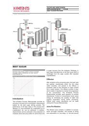
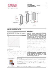
The K-<strong>Patents</strong> <strong>inline</strong> <strong>refractometer</strong> is an instrument <strong>for</strong> measuring liquid concentration in the <strong>pr</strong>ocess line.<br />
The measurement is based on the refraction of light in the <strong>pr</strong>ocess medium, an accurate and safe way of<br />
measuring liquid concentration.<br />
The <strong>refractometer</strong> sensor (A in figure Figure 1.1), mounted <strong>inline</strong>, sends a ray of light into the <strong>pr</strong>ocess<br />
medium and measures the angle in which the light is refracted back from the liquid. This in<strong>for</strong>mation is<br />
then sent via the interconnecting cable (B) to the Indicating transmitter (C). The Indicating transmitter (IT-<br />
R) then calculates the concentration of the <strong>pr</strong>ocess liquid based on the refractive angle, taking temperature<br />
and <strong>pr</strong>e-defined <strong>pr</strong>ocess conditions into account. The output the IT-R <strong>pr</strong>ovides is a 4 to 20 mA DC output<br />
signal <strong>pr</strong>oportional to <strong>pr</strong>ocess solution concentration, but a serial output is also available as a standard.<br />
A B C D<br />
7<br />
4<br />
8<br />
5<br />
9<br />
6<br />
K-PATENTS<br />
1<br />
2<br />
3<br />
0<br />
- ENTER RESET<br />
A: Sensor<br />
B: Interconnecting cable<br />
C: Indicating Transmitter<br />
Figure 1.1<br />
Refractometer equipment.<br />
1.1 PR-<strong>03</strong> <strong>refractometer</strong> models<br />
The basic system of a sensor and an Indicating transmitter connected with a cable is the same in all PR-<strong>03</strong><br />
Inline <strong>refractometer</strong> models. However, there are different sensor models, each adapted <strong>for</strong> different <strong>pr</strong>ocess<br />
requirements.<br />
The Sanitary <strong>refractometer</strong> sensor PR-<strong>03</strong>-A and the Probe <strong>refractometer</strong> sensor PR-<strong>03</strong>-P both meet<br />
the 3-A Sanitary Standard requirements. The model PR-<strong>03</strong>-A is an all-purpose instrument <strong>for</strong> a variety of<br />
alimentary <strong>pr</strong>ocesses while the PR-<strong>03</strong>-P is especially designed <strong>for</strong> cookers and tanks and can even be used<br />
in combination with a scraper in alimentary as well as other <strong>pr</strong>ocesses.<br />
The Compact <strong>pr</strong>ocess <strong>refractometer</strong> PR-<strong>03</strong>-D is an all-round instrument <strong>for</strong> measuring the concentration<br />
of a wide range of chemicals and liquids. The Process <strong>refractometer</strong> PR-<strong>03</strong>-M is built <strong>for</strong> chemically<br />
aggressive solutions and ultra-pure <strong>pr</strong>ocesses, all of its wetted parts are made of non-metallic materials.<br />
The Valve body <strong>refractometer</strong> PR-<strong>03</strong>-W is very similar to the Process <strong>refractometer</strong> PR-<strong>03</strong>-M, but the<br />
special valve body makes it possibly to use it in large-scale <strong>pr</strong>oduction and large pipelines.<br />
The model number of a <strong>refractometer</strong> system is displayed on the serial number label on the sensor head<br />
(see Chapter 8, “Sensor specifications and other sensor in<strong>for</strong>mation”). The serial numbers on the sensor<br />
identification label (see Chapter 8) and the transmitter’s identification label (see Chapter 9) should always<br />
match.
2 PR-<strong>03</strong> <strong>instruction</strong> <strong>manual</strong><br />
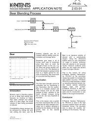
1.2 Principle of measurement<br />
The K-<strong>Patents</strong> <strong>inline</strong> <strong>refractometer</strong> sensor determines the refractive index (R.I.) of the <strong>pr</strong>ocess solution by<br />
measuring the critical angle of refraction. Light from a light source ((L) in Figure 1.2) in the sensor is<br />
directed to this interface. Two of the <strong>pr</strong>ism surfaces (M) are total-reflecting mirrors bending the light rays<br />
that thus meet the interface at different angles.<br />
L<br />
A C B<br />
P<br />
M<br />
M<br />
S<br />
Figure 1.2<br />
Refractometer <strong>pr</strong>inciple<br />
The reflected rays of light <strong>for</strong>m an image (ACB), where (C) is the position of the critical angle ray. The<br />
rays at (A) are totally reflected at the <strong>pr</strong>ocess interface, the rays at (B) are partially reflected and partially<br />
refracted into the <strong>pr</strong>ocess solution. In this way the optical image is divided into a light area (A) and a dark<br />
area (B). The position of the borderline (C) between the areas shows the value of the critical angle and thus<br />
of the refractive index (R.I.) of the <strong>pr</strong>ocess solution.<br />
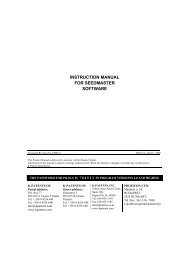
The R.I. changes with the <strong>pr</strong>ocess solution temperature and concentration. In higher temperatures the R.I. is<br />
smaller than in room temperature (standard R.I. 25 ◦ C). When the concentration changes, the R.I. normally<br />
increases when the concentration increases. From this follows that the optical image changes with the<br />
<strong>pr</strong>ocess solution concentration as shown in Figure 1.3. The color of the solution, gas bubbles or undissolved<br />
particles do not affect the result.<br />
B<br />
C<br />
B<br />
A<br />
C<br />
A<br />
Low concentration<br />
Figure 1.3<br />
Optical images<br />
High concentration<br />
The optical image thus achieved is converted to an electric signal by a digitizer inside the sensor. This<br />
electric signal is then sent via an interconnecting cable to the Indicating transmitter’s micro<strong>pr</strong>ocessor <strong>for</strong><br />
further <strong>pr</strong>ocessing, displaying and transmitting.
1 Introduction 3<br />
1.3 General safety considerations<br />
The <strong>pr</strong>ocess medium may be hot or otherwise hazardous. Use shields and <strong>pr</strong>otective clothing adequate <strong>for</strong><br />
the <strong>pr</strong>ocess medium - do not rely on avoidance of contact with the <strong>pr</strong>ocess medium.<br />
Precautions when removing the sensor from the <strong>pr</strong>ocess line:<br />
• Make positively sure that the <strong>pr</strong>ocess line is not under <strong>pr</strong>essure. Open a vent valve to the atmosphere.<br />
• For a <strong>pr</strong>ism wash system, close a hand valve <strong>for</strong> the wash medium and disable the wash valve.<br />
• Loosen the clamp cautiously, be <strong>pr</strong>epared to tighten again.<br />
• Be out of the way of any possible splash and ensure the possibility of escape.<br />
• After removal of the sensor, it may be necessary to mount a blind cover <strong>for</strong> security reasons.<br />
1.4 Warranty<br />
K-<strong>Patents</strong> warrants that all <strong>pr</strong>oducts made by K-<strong>Patents</strong> shall be free of defects in material and workmanship.<br />
K-<strong>Patents</strong> agrees to either replace or repair free of charge, any such <strong>pr</strong>oduct or part thereof which shall be<br />
returned to the nearest authorized K-<strong>Patents</strong> repair facility within two (2) years from the date of delivery.<br />
Be<strong>for</strong>e returning a defective <strong>pr</strong>oduct <strong>for</strong> service or replacement, please contact K-<strong>Patents</strong> or your nearest<br />
K-<strong>Patents</strong> re<strong>pr</strong>esentative (see http://www.kpatents.com/ <strong>for</strong> contact in<strong>for</strong>mation). For the health and safety<br />
of personnel handling your return, clean the instrument, especially the parts that have been in contact with<br />
the <strong>pr</strong>ocess liquid, be<strong>for</strong>e packing it. Ship the cleaned instrument to the address given to you.<br />
1.5 Disposal<br />
When disposing of an obsolete instrument or any parts of an instrument, please observe the local and national<br />
requirements <strong>for</strong> the disposal of electrical and electronic equipment. The steel Indicating transmitter<br />
enclosure and the aluminium or stainless steel sensor housing can be recycled with other metallic waste of<br />
the same type.
4 PR-<strong>03</strong> <strong>instruction</strong> <strong>manual</strong>
2 Inline <strong>refractometer</strong> sensor 5<br />
2 Inline <strong>refractometer</strong> sensor<br />
2.1 Sensor description<br />
Figure 2.1 below shows cutaway pictures of two <strong>refractometer</strong> sensors. These sensors are otherwise similar<br />
in structure, but the sensor on the right has a longer <strong>pr</strong>obe. The short <strong>pr</strong>obe is the more common<br />
<strong>refractometer</strong> sensor design, only the Probe Refractometer PR-<strong>03</strong>-P is built like the sensor to the right in<br />
Figure 2.1.<br />
In the sensor the measurement <strong>pr</strong>ism (A) is flush mounted to the surface of the <strong>pr</strong>obe tip. The <strong>pr</strong>ism is fixed<br />
to the analyzer module (C) which is s<strong>pr</strong>ing-loaded (D) against the <strong>pr</strong>ism gasket (B). The light source is a<br />
light emitting diode (K). The digital image detector (G) is a CCD element consisting of 1024 photocells<br />
in a row integrated on one chip. The image sensor (G) is <strong>pr</strong>otected from the <strong>pr</strong>ocess heat by two isolating<br />
parts (H). Excess heat is transferred by a heat conductor (I) to the air cooled sensor cover (J). For automatic<br />
temperature compensation, the sensor tip contains a <strong>pr</strong>ocess temperature <strong>pr</strong>obe (F), Pt-100.<br />
Figure 2.1<br />
PR-<strong>03</strong> sensor structure<br />
The image detector output is a pulse train as shown in Figure 2.2. The number of high pulses corresponds<br />
to the position of the shadow edge in the optical image and is thus a direct measure of the critical angle.<br />
The image digitizer (E) trans<strong>for</strong>ms this pulse train to a serial digital signal. This serial signal transmits to<br />
the Indicating transmitter a package containing temperature data and a complete description of the optical<br />
image.<br />
Note: K-<strong>Patents</strong> in-line <strong>refractometer</strong> PR-<strong>03</strong> is using a 1024-pixel CCD-element. To keep the supporting<br />
transmitter software compatible <strong>for</strong> all K-<strong>Patents</strong> <strong>refractometer</strong>s, the TEST value (= number of photocells<br />
at the light side) is scaled to the range 8-248. That is, <strong>for</strong> PR-<strong>03</strong> the number of high pulses (Figure 2.2) is<br />
divided by four.
6 PR-<strong>03</strong> <strong>instruction</strong> <strong>manual</strong><br />
a: optical image<br />
b: detector window and the photocells<br />
V<br />
TIME<br />
c: pulse train from detector<br />
Figure 2.2<br />
Image detector system<br />
Note: In the Probe <strong>refractometer</strong> PR-<strong>03</strong>-P the image is inverted by the optics. That is, the shadow comes<br />
in from the left. The image is inverted back to normal (as in Figure 2.2) by the indicating transmitter be<strong>for</strong>e<br />
any further <strong>pr</strong>ocessing.<br />
2.2 Mounting the sensor<br />
The sensor mounting location should be chosen with care to ensure that you get reliable readings from<br />
your <strong>pr</strong>ocess. Some basic rules, described in this section, apply to all sensor models. The model specific<br />
<strong>instruction</strong>s can be found in Chapter 8.<br />
2.2.1 Choosing sensor mounting location<br />
A K-<strong>Patents</strong> in-line <strong>refractometer</strong> sensor can be located either indoors or outdoors in most climates. However,<br />
if the sensor is located outdoors, some basic <strong>pr</strong>otection against direct exposure to sunlight and rain<br />
should be <strong>pr</strong>ovided. Special care should be taken if the pipe wall is translucent (e.g. of fiberglass), because<br />
light from outside reaching the <strong>pr</strong>ism will disturb the measurement.<br />
The mounting location needs to be such that sediments or gas bubbles cannot accumulate by the sensor.<br />
Good flow velocity is essential in keeping the <strong>pr</strong>ism clean.<br />
Always check that the sensor head is kept cool enough, the sensor head should not be too hot to keep a hand<br />
on. The red sensor cover should not be exposed to high temperature radiation. Normally, draft and natural<br />
convection <strong>pr</strong>ovide sufficient air cooling if the air gets to flow freely around the sensor head.<br />
Additional cooling is necessary when the ambient temperature is higher than 45 ◦ C (113 ◦ F) or when the<br />
<strong>pr</strong>ocess temperature is above 110 ◦ C (230 ◦ F) and the ambient temperature is above 35 ◦ C (95 ◦ F). The aircooling<br />
is im<strong>pr</strong>oved by blowing <strong>pr</strong>essurized air against the red sensor cover. The <strong>pr</strong>essurized air can be<br />
supplied by the ventilation system. If no air is available it is also possible to wind a copper coil <strong>for</strong> cooling<br />
water around the sensor head cover.
2 Inline <strong>refractometer</strong> sensor 7<br />
Important: Always mount the sensor so that the cable plug socket on the sensor head points downwards,<br />
i.e. so that when the interconnecting cable is plugged into the sensor, the cable hangs down.<br />
Figure 2.3<br />
Refractometer cable plug direction<br />
2.2.2 Check list <strong>for</strong> pipe mounting (PR-<strong>03</strong>-A, PR-<strong>03</strong>-D, PR-<strong>03</strong>-M)<br />
1. If the <strong>pr</strong>ocess pipe diameter varies, select the position with the smallest diameter (and accordingly<br />
highest velocity). Then the <strong>pr</strong>ism keeps better clean. If the pipe is coned up after a pump, valve or<br />
magnetic flow meter, then add a length of straight pipe be<strong>for</strong>e the coning up and mount the <strong>refractometer</strong><br />
there.<br />
2. If the <strong>refractometer</strong> is used in a feed-back control loop, make the time lag short. E.g. when a dilution<br />
valve is controlled, mount the <strong>refractometer</strong> as near the dilution point as possible.<br />
3. If the temperature varies along the <strong>pr</strong>ocess pipe, select the position with the highest temperature. Then<br />
the risk of <strong>pr</strong>ism coating is minimized, because higher temperature means higher solubility and also<br />
lower viscosity.<br />
4. Often the position with the highest <strong>pr</strong>essure (= after pump + be<strong>for</strong>e valve) has favorable flow conditions<br />
without sedimentation or air trapping risks.<br />
5. The sensor should be conveniently accessible <strong>for</strong> service.<br />
Important: If the <strong>pr</strong>ocess pipe vibrates, support the pipe. A vibrating pipe might damage the <strong>inline</strong> sensor<br />
mounted on it.
8 PR-<strong>03</strong> <strong>instruction</strong> <strong>manual</strong><br />
2.2.3 Check list <strong>for</strong> mounting in a tank, a vessel or a large pipe (PR-<strong>03</strong>-P)<br />
A Probe sensor PR-<strong>03</strong>-P can be inserted with a sanitary clamp into tanks and vessels which either don’t<br />
have a scraper or where the mixer doesn’t touch the vessel wall. A Probe sensor can also be flush mounted<br />
in a cooker where the scraper touches the wall.<br />
1. Both the inserted and the flush mounted Probe sensor are mounted on the vessel wall with the cable<br />
socket downwards.<br />
2. The inserted <strong>pr</strong>obe sensor is mounted close to a stirrer to ensure re<strong>pr</strong>esentative sample of the <strong>pr</strong>ocess<br />
liquid and to keep the <strong>pr</strong>ism clean.<br />
3. The sensor should be conveniently accessible <strong>for</strong> service.
3 Indicating transmitter (IT-R) 9<br />
3 Indicating transmitter (IT-R)<br />
3.1 Indicating transmitter description<br />
The indicating transmitter (abbr. IT-R) is a small, specialized computer designed to <strong>pr</strong>ocess data received<br />
from the sensor. The Indicating transmitter enclosure (see Figure 3.1) contains a front panel with a Liquid<br />
Crystal Display (LCD) and a keyboard. The IT-R’s micro<strong>pr</strong>ocessor system and the power supply are hidden<br />
under the front panel that swings open <strong>for</strong> service. Knockout padlock <strong>pr</strong>ovisions <strong>for</strong> locks are included in<br />
the enclosure’s both cover latches to <strong>pr</strong>event unauthorized access.<br />
A B C D<br />
7<br />
8<br />
9<br />
K-PATENTS<br />
PROCESS INSTRUMENTS<br />
4<br />
5<br />
6<br />
1<br />
2<br />
3<br />
0<br />
.<br />
- ENTER RESET<br />
Figure 3.1<br />
The Indicating transmitter enclosure<br />
The IT-R receives from the sensor data that describes the optical image and gives the <strong>pr</strong>ocess temperature.<br />
It then displays the optical image (Figure 1.3) and implements an image analyzing algorithm (Figure 3.2),<br />
which identifies the exact position of the shadow edge (Figure 2.2). Finally, the micro<strong>pr</strong>ocessor system<br />
linearizes the concentration reading (example in Figure 3.3), and per<strong>for</strong>ms an automatic temperature compensation.<br />
70<br />
60<br />
BRIX<br />
Raw data<br />
Curve fitted to the data<br />
50<br />
40<br />
30<br />
20<br />
10<br />
R.I.<br />
1.35 1.40 1.45<br />
Figure 3.2<br />
Image analyzing algorithm<br />
Figure 3.3<br />
A Brix diagram<br />
The IT-R output signals are a 4-20 mA concentration signal and a serial output signal, RS232 or RS485<br />
alternatively, which enables connections to <strong>for</strong> example a PC (See Section 3.2.3).<br />
In the IT-R there are also two built-in signal relays on the power supply card. These signal relays can<br />
be configured to any relay function except <strong>pr</strong>econditioning or wash control (see Section 5.7, “Configuring<br />
relays”).
10 PR-<strong>03</strong> <strong>instruction</strong> <strong>manual</strong><br />
Furthermore, the Indicating transmitter accepts four input switches which can be configured <strong>for</strong> example to<br />
signal HOLD during external wash or to contain different scale settings each (see Section 5.6, “Configuring<br />
input switches”).<br />
3.2 Mounting Indicating transmitter<br />
The Indicating transmitter should <strong>pr</strong>eferably be located in an easily accessible, well lighted and dry area.<br />
The enclosure must not be exposed to rain or direct sunlight. Avoid vibration. Take interconnecting cable<br />
length into consideration when choosing mounting location.<br />
The enclosure is mounted vertically on an u<strong>pr</strong>ight surface (wall) using four mounting feet, see Figure 3.4.<br />
Important: Do not drill mounting holes in the enclosure as that will affect the <strong>pr</strong>otection class of the<br />
enclosure and may expose the electronics of the IT-R.<br />
Figure 3.4<br />
Mounting the Indicating transmitter<br />
Note: The LCD display has an operating temperature range of 0–50 ◦ C and a storage temperature range of<br />
-20–60 ◦ C. If exposed to very low storage temperatures, let the IT-R reach the ambient temperature be<strong>for</strong>e<br />
turning it on, as the LCD may not be able to display anything in temperatures below zero.<br />
3.2.1 Mounting the Interconnecting cable<br />
The interconnecting cable PR-8300 is made at the K-<strong>Patents</strong> factory according to the specifications given<br />
in your order (see Section 9.4). The maximum length of an interconnecting cable is 100 meters (330 feet).<br />
When mounting the cable, check that the ends easily reach the sensor respectively the IT-R.<br />
!<br />
Warning! Do not try to shorten or lengthen the interconnecting cable! If a new cable is needed <strong>for</strong> example<br />
after the IT-R has been moved further away from the <strong>pr</strong>ocess line, you can order a spare part cable from<br />
K-<strong>Patents</strong> or your local K-<strong>Patents</strong> re<strong>pr</strong>esentative.
3 Indicating transmitter (IT-R) 11<br />
3.2.2 Electrical connections<br />
All the electric terminals of the Indicating transmitter are on the Power supply card (Figure 3.5).<br />
SERIAL CABLE<br />
(pc)<br />
SWITCHES<br />
ACCESSORY UNIT<br />
(serial bus)<br />
POWER<br />
SELECTOR<br />
RELAYS<br />
SENSOR<br />
CABLE<br />
11<br />
POWER<br />
CONNECTION<br />
Figure 3.5<br />
Power supply card layout<br />
To access the Power supply card, first open the enclosure cover. Then loosen the two screws on the righthand<br />
corners of the front panel and swing open the front panel to see the card.<br />
Figure 3.6<br />
IT-R with opened front panel.
12 PR-<strong>03</strong> <strong>instruction</strong> <strong>manual</strong><br />
3.2.2.1 Connecting with sensor<br />
The sensor end of the interconnecting cable is terminated by a plug. The plug goes into the cable plug<br />
socket on the sensor head. After connecting the cable with the sensor, join the two connector <strong>pr</strong>otecting<br />
caps to keep them clean inside.<br />
The Indicating transmitter end of the interconnecting cable has leads numbered from 1 to 7 to be connected<br />
to the terminals with the same numbers on the Power supply card. The seven leads to the plug on the cable<br />
are colored Red, Blue, Black, Red, Blue, Black and Black.<br />
3.2.2.2 AC power connection<br />
The <strong>pr</strong>imary AC power is connected to a separate terminal strip 39/40/41 marked POWER in the lower<br />
right-hand corner of the Power supply card (Figure 3.5). The three terminals are marked 39/L, 40/N and<br />
41/ground symbol. The connection is made by inserting each lead into the corresponding slot and tightening<br />
the screws above the slots (Figure 3.7).<br />
The power terminals Line and Neutral are directly connected to the trans<strong>for</strong>mer <strong>pr</strong>imary loop, and galvanically<br />
separated from the rest of the instrument. The ground terminal (41) is connected to the bottom plate of<br />
the Indicating transmitter, to the trans<strong>for</strong>mer shield winding and to the outer shield of the interconnecting<br />
cable.<br />
LINE<br />
NEUTRAL<br />
GROUND<br />
Figure 3.7<br />
Power terminals on the Power supply card<br />
Important: Be<strong>for</strong>e connecting the IT-R power, check the position of the power selector switch, marked<br />
SW2 on the Power supply card. The power selector switch has two positions: 220–240 V/50–60 Hz or<br />
100–115 V/50–60 Hz.<br />
Figure 3.8<br />
Power selector switch in the 220 V position<br />
3.2.2.3 +24 V DC power connection<br />
The <strong>pr</strong>imary DC power is connected to a separate terminal strip 39/40/41 marked POWER in the lower righthand<br />
corner of the Power supply card (Figure 3.5). The terminals are marked 39/+24V, 40/0 and 41/ground
3 Indicating transmitter (IT-R) 13<br />
symbol. The connection is made by inserting each lead into the corresponding slot and tightening the screws<br />
above the slots (Figure 3.7).<br />
The ground terminal (41) is connected to the bottom plate of the Indicating transmitter, to the trans<strong>for</strong>mer<br />
shield winding and to the outer shield of the interconnecting cable.<br />
Important: The power selector switch on the Power supply card, marked SW2, must be in 110 position<br />
(Figure 3.9) when input voltage is +24 V DC. If the switch is in the wrong position, the <strong>refractometer</strong> system<br />
does not work.<br />
Figure 3.9<br />
Power selector switch in the 110 V +24 V DC position<br />
3.2.2.4 Current output connection<br />
The current output connection terminals are 25 and 26. The terminal 25 is plus (+) and 26 minus (-) <strong>for</strong> the<br />
4-20 mA output signal (The detailed signal specifications are listed in Section 9.4, “IT-R Specifications”).<br />
Recorders, controllers, indicators etc. must be connected to <strong>for</strong>m a closed current loop, starting from terminal<br />
25 passing each device, in at plus and out at minus, ending at terminal 26.<br />
Important: Be careful not to exceed the specified load resistance, 1800 Ohm.<br />
3.2.2.5 Serial bus connections<br />
Terminals 8-14 on the Power supply card <strong>pr</strong>ovide connection to K-<strong>Patents</strong> accessory units, like a Relay Unit<br />
(see Section 4.1) and External output unit (see Section 4.2). The connection cable is of the same type as the<br />
interconnecting cable and follows the same specifications (see Section 9.4). See Section 4.1.3, “Relay unit<br />
mounting and connections” and Section 4.2.2, “External output unit mounting and connections” <strong>for</strong> more<br />
in<strong>for</strong>mation.<br />
3.2.2.6 Input switch connections<br />
Altogether four input switches A, B, C and D can be connected: Terminals 27-A, 28-B, 29-C, 30-D, 31-<br />
Common, Figure 3.10. To use a switch, you will have to connect that switch with terminal 31, which short<br />
circuits that switch. Thus, to use switch A, connect terminal 27 with terminal 31.<br />
The switches may be separate, or together in one rotary switch. Input switch functions are configured<br />
through software, Section 5.6. Most commonly input switches are used <strong>for</strong> easy switching between calibration<br />
settings <strong>for</strong> different <strong>pr</strong>ocess mediums or <strong>for</strong> <strong>pr</strong>eventing accidental or unauthorized calibration changes.<br />
A 5V voltage is <strong>pr</strong>ovided over each switch. The switch terminals are all galvanically isolated from ground<br />
and from the rest of the electronics.
14 PR-<strong>03</strong> <strong>instruction</strong> <strong>manual</strong><br />
SWITCHES<br />
SWITCHES<br />
27 28 29 30 31<br />
27 28 29 30 31<br />
A<br />
B C D<br />
A<br />
B<br />
C<br />
D<br />
Figure 3.10<br />
Input switch connections<br />
3.2.3 Serial output connections: connecting a computer with the IT-R<br />
The serial output connections on the Power supply card allow you to download in<strong>for</strong>mation from the IT-R<br />
with a PC computer that has a 9-pin COM port (or a USB-to-COM adapter that simulates a 9-pin COM<br />
port).<br />
Note: The serial output connection is <strong>for</strong> output only, i.e. it cannot be used to give commands to the IT-R.<br />
To connect your PC with an IT-R to download <strong>pr</strong>ocess data, you need to order a communications package<br />
from K-<strong>Patents</strong>. The package contains a cable with a plug <strong>for</strong> the P3 plug connector on the Indicating<br />
transmitter Power supply card. The other end of the cable is a 9-hole COM plug <strong>for</strong> your computer’s COM<br />
port.<br />
Serial connection cable plugs Cable plugged into an IT-R<br />
Figure 3.11 Serial (PC) connection
3 Indicating transmitter (IT-R) 15<br />
The K-<strong>Patents</strong> communications package contains Windows software <strong>for</strong> downloading data from the IT-R.<br />
The software has been <strong>pr</strong>eset so that it normally starts directly after the installation and it has built-in<br />
<strong>instruction</strong>s. However, you can also use any standard communications software to download data. In<br />
such case see Section 9.4.2, “Serial output specifications” <strong>for</strong> more in<strong>for</strong>mation on the data <strong>for</strong>mat and<br />
the communications settings.<br />
3.2.4 Demo mode connection<br />
The Indicating transmitter can be used as stand-alone <strong>for</strong> demos and to train keyboard handling. The built-in<br />
Demo <strong>pr</strong>ogram contains a sensor simulator, so when the demo connection is on, you only need an IT-R to<br />
show how the <strong>refractometer</strong> system works.<br />
The Demo mode is activated by changing connections on the Power supply card:<br />
1. Turn off the power from the IT-R. Open the enclosure cover and the front panel.<br />
2. Disconnect the sensor cable (connections 1-7) (Section 3.2.2.1) and all connections to Serial bus (connections<br />
8-14), i.e. all external units (see Section 4.1.3 and Section 4.2.2).<br />
3. Connect terminal 1 to terminal 8 and terminal 2 to terminal 9, Figure 3.12<br />
SERIAL BUS RS-485 SWITCHES<br />
8<br />
9<br />
10 11 12 13 14 15 16 17 18<br />
27 28 29 30 31<br />
SENSOR<br />
4-20mA<br />
RLY1 RLY2<br />
+ -<br />
1<br />
2<br />
3<br />
4<br />
5<br />
6<br />
7<br />
43 44 45 46 25 26<br />
47 48 49 50<br />
Figure 3.12<br />
Making demo connection<br />
4. Close the front panel and turn on the IT-R.
16 PR-<strong>03</strong> <strong>instruction</strong> <strong>manual</strong><br />
Note: When the IT-R has been turned on in demo mode, a small star appears in the top left corner of the<br />
display. Because the external units have been disconnected, the Normal display will not have a soft key <strong>for</strong><br />
Prism wash. Other than that, the Indicating transmitter will behave as if it was connected to a sensor in the<br />
<strong>pr</strong>ocess line.<br />
*<br />
CONC<br />
68.0%<br />
PROCESS TEMPERATURE: 31.2 °C<br />
STANDARD RI(25°C): 1.4194<br />
TEST: 115.7<br />
Normal operation<br />
Calibrate<br />
Display<br />
A B C D<br />
Figure 3.13<br />
IT-R display when in demo mode<br />
Note: For more in<strong>for</strong>mation on how to use the Indicating transmitter, see Section 5.3, “Using Indicating<br />
transmitter”.<br />
3.3 Cable signals between IT-R and sensor<br />
SEN+<br />
SEN-<br />
GND<br />
+24V<br />
0V<br />
GND<br />
PGND<br />
1<br />
2<br />
3<br />
4<br />
5<br />
6<br />
7<br />
RED<br />
BLUE<br />
RED<br />
BLUE<br />
RED<br />
BLUE<br />
RED<br />
BLUE<br />
1<br />
WHITE<br />
1<br />
2 2<br />
3 3<br />
BLACK<br />
4 4<br />
BLUE<br />
5 5<br />
BROWN<br />
6 6<br />
Cable<br />
Plug<br />
Image Digitizer<br />
Indicating transmitter<br />
Figure 3.14<br />
Cable signals
4 Accessory units 17<br />
4 Accessory units<br />
4.1 Separate relay units<br />
When necessary, a K-<strong>Patents</strong> <strong>inline</strong> <strong>refractometer</strong> system can be equipped with a separate relay unit with<br />
either four (PR-7080) or two (-WR) relays. The separate relay units can be added to any <strong>refractometer</strong> model<br />
when additional relays are needed.<br />
Unlike the built-in relays, both separate relay units can be configured <strong>for</strong> <strong>pr</strong>econditioning and <strong>pr</strong>ism wash.<br />
That is, if a <strong>pr</strong>ism wash (Sanitary <strong>refractometer</strong> PR-<strong>03</strong>-A and Probe <strong>refractometer</strong> PR-<strong>03</strong>-P only) is installed<br />
because of sticky <strong>pr</strong>ocess medium, a separate relay unit is also needed.<br />
4.1.1 Relay unit description<br />
Both separate relay units are built in an enclosure with IP 65 (Nema 4X) classification. Figure 4.1 shows<br />
the dimensions of the four-relay unit PR-7080 and the two-relay unit -WR.<br />
PR-7080<br />
Figure 4.1<br />
Relay unit dimensions<br />
-WR<br />
To see the relays and to make all necessary connections, open the screws in the four top corners of the relay<br />
enclosure and lift off the enclosure cover.<br />
The cable fittings are delivered as one of the three alternatives:<br />
US 1/2 NPT-TYPE ST-1 conduit hubs 4 pcs<br />
European BF11/PG11 cable glands 4 pcs<br />
M20x1.5 cable glands<br />
4 pcs
18 PR-<strong>03</strong> <strong>instruction</strong> <strong>manual</strong><br />
4.1.1.1 Relay unit PR-7080<br />
The Relay unit PR-7080 contains 4 relays from left to right: Relay A, relay B, relay C and relay D. There is<br />
a yellow LED above each relay. If the LED is lighted, the corresponding relay is ON and the output contact<br />
is closed. There is also one green and one red indicator led to in<strong>for</strong>m on system status. After startup the red<br />
led is lighted only when the relay unit has <strong>pr</strong>oblem.<br />
The Relay unit PR-7080 is connected with the IT-R with an interconnecting cable PR-8011 . The last three<br />
numbers in the cable code indicate the cable length in meters, the shortest available cable is PR-8011-001<br />
(1 meter; 3.3 feet) and the longest possible cable is PR-8011-100 (100 meters; 330 feet).<br />
4.1.1.2 Relay unit -WR<br />
The Relay Unit -WR contains 2 relays from left to right: Relay A and Relay B. There is a yellow LED<br />
above each relay. If the LED is lighted, the corresponding relay is ON and the output contact is closed.<br />
4.1.2 Prism wash system description<br />
Deposit build-up on the <strong>pr</strong>ism surface disturbs the measurement. Look out <strong>for</strong> an abnormally high concentration<br />
reading, low slope value or an upward CONC drift.<br />
In most applications the <strong>pr</strong>ism will keep clean due to the self-cleaning effect. If coating occurs, check the<br />
following:<br />
− Sufficient flow velocity, see Section 2.2.2, “Check list <strong>for</strong> pipe mounting (PR-<strong>03</strong>-A, PR-<strong>03</strong>-D, PR-<strong>03</strong>-M)”.<br />
− A temperature difference between <strong>pr</strong>ocess fluid and sensor <strong>pr</strong>obe may cause coating. This may happen<br />
with small flows if the thermal insulation is inadequate. In some cases it helps to insulate also the clamp<br />
connector.<br />
In case of a coating <strong>pr</strong>oblem, the <strong>pr</strong>eferred solution is to try to increase the flow velocity, e.g. by installing<br />
a pipe portion with smaller diameter. Installing a wash nozzle can be considered, if increasing the velocity<br />
does not <strong>pr</strong>ovide a solution (Section 4.1.4).<br />
Three alternative media can be used <strong>for</strong> <strong>pr</strong>ism wash: steam, water, high <strong>pr</strong>essure water. Only external relays<br />
(accessory units) can be configured to control the <strong>pr</strong>ism wash cycle, see Section 5.9 “Configuring automatic<br />
<strong>pr</strong>ism wash”.<br />
4.1.3 Relay unit mounting and connections<br />
Note: When mounting a separate relay unit, seal all unused fittings with blind washers.<br />
4.1.3.1 Mounting and connecting Relay unit PR-7080<br />
The four-relay Relay unit PR-7080 is mounted on a wall or similar vertical surface using its four mounting<br />
feet. Take the length of the interconnecting cable PR-8011 and easy access <strong>for</strong> service into account when<br />
choosing mounting spot <strong>for</strong> the Relay unit.<br />
Open the screws on the Relay unit and lift off cover to get access to the relay card to make the connections.<br />
The relay contacts go to the connector strip (Figure 4.2) on the relay unit card.
4 Accessory units 19<br />
A B C D<br />
44 45 46 47 48 49 50 51<br />
Figure 4.2<br />
Relay unit PR-7080 connector strip<br />
Connect the numbered leads of the interconnecting cable with the same numbers (8-14) on the serial bus.<br />
Then <strong>pr</strong>oceed to connect the cable with your <strong>refractometer</strong> system. If you have an External output unit, the<br />
Relay unit is connected to that. If no other external units are used, the Relay unit connects directly with the<br />
IT-R (Figure 4.3).<br />
Indicating<br />
transmitter<br />
8-14<br />
External output unit<br />
Relay unit<br />
A B<br />
8-14 8-14<br />
8-14<br />
PR-8011<br />
PR-8011<br />
Indicating<br />
transmitter<br />
8-14<br />
Relay unit<br />
8-14<br />
PR-8011<br />
Figure 4.3<br />
Connecting Relay unit PR-7080<br />
Important: Be<strong>for</strong>e connecting the relay unit with your <strong>refractometer</strong> system, power off your system. If you<br />
have an external output unit, open its cover to access the card inside <strong>for</strong> connections. If you don’t have an<br />
external output unit, open the IT-R’s enclosure and display panel to access the <strong>pr</strong>ocessor card.<br />
Connect the numbered leads of the free cable end with terminals with the same numbers (8-14) on the<br />
serial bus output (serial bus B) on the Output unit card or on the serial bus on the Indicating transmitter’s<br />
<strong>pr</strong>ocessor card.
20 PR-<strong>03</strong> <strong>instruction</strong> <strong>manual</strong><br />
4.1.3.2 Mounting and connecting Relay unit -WR<br />
The Relay unit -WR is always mounted directly underneath the IT-R. If the IT-R and the Relay unit -WR are<br />
delivered together, they are already fully connected. If the Relay unit is delivered separately, the connection<br />
cable is included in the Relay unit delivery. The cable is plugged in the P2 plug on the IT-R’s <strong>pr</strong>ocessor<br />
card (next to the sensor cable, see Figure 3.5). The relay contacts go to the connector strip.<br />
4.1.4 Mounting and connecting <strong>pr</strong>ism wash systems<br />
The <strong>pr</strong>ism wash system <strong>for</strong> steam is described by Figures 4.7 and 4.8 and <strong>for</strong> high <strong>pr</strong>essure water by Figure<br />
4.9.<br />
4.1.4.1 Recommended wash <strong>pr</strong>essures and times<br />
The recommended wash <strong>pr</strong>essures and times are given in Table 4.1 below.<br />
Wash medium <strong>pr</strong>essure<br />
Minimum Maximum Wash time Recovery Interval<br />
above <strong>pr</strong>ocess allowed<br />
<strong>pr</strong>essure<br />
<strong>pr</strong>essure<br />
Steam 2 bar (30 psi) 6 bar (90 psi) 3–5 s 20–30 s 20–30 min<br />
Water 2 bar (30 psi) 6 bar (90 psi) 10–15 s 20–30 s 10–20 min<br />
High <strong>pr</strong>essure water 40 bar (600 psi) 70 bar (1000 psi) 10–15 s 20–30 s 10–20 min<br />
Table 4.1<br />
Recommended <strong>pr</strong>ism wash parameters<br />
Important: In steam wash, do not exceed the recommended wash times, because some <strong>pr</strong>ocess media may<br />
burn to the <strong>pr</strong>ism surface if steamed <strong>for</strong> longer time. In case of coating, shorten the wash interval.<br />
Note: In water wash, water temperature should be above the <strong>pr</strong>ocess temperature.<br />
Note: The check valve <strong>pr</strong>essure drop is 0.7 bar (10 psi).<br />
4.1.4.2 Prism wash nozzles<br />
Select wash nozzle according to wash medium and <strong>refractometer</strong> model, Table 4.2.<br />
PR-<strong>03</strong>-A<br />
Pressurized water sanitary nozzle -WP<br />
Steam sanitary nozzle -SN<br />
Water nozzle -WN<br />
PR-3366<br />
PR-3365<br />
PR-3364<br />
Table 4.2<br />
Prism wash nozzle selection
4 Accessory units 21<br />
The three versions of a <strong>pr</strong>ism wash nozzle are shown in Figure 4.4. How they are mounted to the <strong>pr</strong>ocess is<br />
shown in Figure 4.5, which also shows the connection of a check valve. K-<strong>Patents</strong> <strong>pr</strong>ovides flow cells with<br />
stud <strong>for</strong> a wash nozzle. Figure 4.6 shows an example with the correct position of the nozzle in relation to<br />
the <strong>pr</strong>ism surface.<br />
Figure 4.4<br />
Wash nozzle selection
22 PR-<strong>03</strong> <strong>instruction</strong> <strong>manual</strong><br />
Figure 4.5<br />
Process connection of a wash nozzle<br />
Figure 4.6<br />
Example of wash nozzle installed in a flow cell
4 Accessory units 23<br />
4.1.4.3 Mounting of <strong>pr</strong>ism wash systems with steam and water<br />
8<br />
12<br />
6<br />
2<br />
FLOW<br />
7<br />
TO DRAIN<br />
RELAY UNIT PR-7080<br />
3<br />
4<br />
AIR<br />
13<br />
1/2"<br />
STEAM<br />
10 5<br />
9<br />
11<br />
13<br />
12<br />
11<br />
10<br />
9<br />
8<br />
7<br />
6<br />
5<br />
4<br />
3<br />
2<br />
1<br />
AC POWER SUPPLY 230/110 V<br />
STEAM PIPE 1/4"<br />
STEAM PIPE 1/2"<br />
SOLENOID CABLE, 3x1 (AWG 17)<br />
STRAINER PR-3342<br />
CHECK VALVE PR-3302<br />
SHUT-OFF VALVE&STEAM TRAP PR-3340-230/110<br />
EFC (ELBOW FLOW CELL)<br />
CABLE PR-8011 BETWEEN INDICATING TRANSMITTER AND RELAY UNIT<br />
CABLE PR-8300 BETWEEN INDICATING TRANSMITTER AND SENSOR<br />
RELAY UNIT PR-7080<br />
SENSOR PR-<strong>03</strong>-A62-HSS<br />
INDICATING TRANSMITTER IT-R<br />
PART PART SPECIFICATIONS<br />
SUPPLIED BY<br />
CUSTOMER 2<br />
CUSTOMER 1<br />
CUSTOMER 1<br />
CUSTOMER 1<br />
K-PATENTS 1<br />
K-PATENTS 1<br />
K-PATENTS 1<br />
K-PATENTS 1<br />
K-PATENTS 1<br />
K-PATENTS 1<br />
K-PATENTS 1<br />
K-PATENTS 1<br />
K-PATENTS 1<br />
1<br />
13<br />
WIRING SEE WRG-314<br />
Figure 4.7<br />
Mounting of a <strong>pr</strong>ism wash system with steam and Relay unit PR-7080
24 PR-<strong>03</strong> <strong>instruction</strong> <strong>manual</strong><br />
11<br />
7<br />
5<br />
2<br />
FLOW<br />
6<br />
TO DRAIN<br />
0<br />
SAFETY<br />
13<br />
SWITCH<br />
4<br />
AIR<br />
POWER<br />
3<br />
1/2"<br />
12<br />
STEAM<br />
14<br />
8<br />
10<br />
9<br />
14 CABLE 2x1 (AWG 17) CUSTOMER 1<br />
13 12 11 10 9 SAFETY SWITCH AC POWER SUPPLY 230/110 V<br />
STEAM PIPE 1/4"<br />
STEAM PIPE 1/2"<br />
SOLENOID CABLE, 3x1 (AWG 17)<br />
CUSTOMER CUSTOMER CUSTOMER CUSTOMER CUSTOMER 1<br />
2<br />
1<br />
1<br />
1<br />
8 7 STRAINER PR-3342<br />
CHECK VALVE PR-3302<br />
K-PATENTS<br />
K-PATENTS 1<br />
1<br />
6 5 4 3 2 1 SHUT-OFF VALVE&STEAM TRAP PR-3340-230/110<br />
EFC (ELBOW FLOW CELL)<br />
CABLE PR-8300 BETWEEN INDICATING TRANSMITTER AND SENSOR WASH RELAY UNIT<br />
SENSOR PR-<strong>03</strong>-A62-HSS<br />
INDICATING TRANSMITTER IT-R<br />
K-PATENTS K-PATENTS K-PATENTS K-PATENTS K-PATENTS K-PATENTS 1<br />
1<br />
1<br />
1<br />
1<br />
1<br />
PART PART SPECIFICATIONS<br />
SUPPLIED BY<br />
WIRING SEE WRG-313<br />
1<br />
12<br />
I<br />
Figure 4.8<br />
Mounting of a <strong>pr</strong>ism wash system with steam and Relay unit -WR
4 Accessory units 25<br />
4.1.4.4 Mounting of <strong>pr</strong>ism wash systems with high <strong>pr</strong>essure water<br />
!<br />
Warning! In high <strong>pr</strong>essure wash systems, <strong>pr</strong>essure increase can occur in a closed pipe section when the<br />
high <strong>pr</strong>essure pump is operated. K–<strong>Patents</strong> recommends to mount a <strong>pr</strong>essure relief valve in the pipe section.<br />
Relief <strong>pr</strong>essure should be according to pipe <strong>pr</strong>essure rating.<br />
7<br />
6<br />
5<br />
FLOW<br />
10<br />
2<br />
9<br />
0<br />
POWER RELAY UNIT<br />
PR-36<strong>03</strong>-___<br />
POWER<br />
MAIN<br />
SWITCH<br />
4<br />
3<br />
12 8<br />
13<br />
11<br />
TAP WATER, TEMP MAX 60 °C / 140 °F<br />
3/8"<br />
13 CABLE 2x1 (AWG 17) CUSTOMER 1<br />
12 11 POWER SUPPLY CABLE 3 METERS FOR HIGH PRESSURE PUMP POWER SUPPLY CABLE 3 METERS FOR WATER VALVE<br />
K-PATENTS CUSTOMER<br />
1<br />
10 HIGH PRESSURE PUMP PR-3602-110/230/400/550 INCLUDING WATER VALVE K-PATENTS<br />
9 POWER RELAY UNIT PR-36<strong>03</strong>-110/230/400/550 K-PATENTS 1<br />
8 AC POWER SUPPLY 230/110 V<br />
CUSTOMER<br />
7 HIGH PRESSURE HOSE 8M<br />
K-PATENTS<br />
6 CHECK VALVE R 1/4" PR-3302<br />
K-P / CUSTOMER<br />
5 EFC (ELBOW FLOW CELL)<br />
K-PATENTS<br />
4 CABLE BETWEEN INDICATING TRANSMITTER AND SENSOR PR-8300<br />
K-PATENTS<br />
3<br />
2<br />
1<br />
WASH RELAY UNIT (WR)<br />
SENSOR PR-<strong>03</strong>-A62-HSS<br />
INDICATING TRANSMITTER IT-R<br />
K-PATENTS<br />
K-PATENTS<br />
K-PATENTS<br />
PART PART SPECIFICATIONS<br />
SUPPLIED BY<br />
1<br />
1<br />
2<br />
1<br />
1<br />
1<br />
1<br />
1<br />
1<br />
1<br />
POWER<br />
1<br />
8<br />
I<br />
Figure 4.9<br />
Mounting summary of <strong>pr</strong>ism wash system <strong>for</strong> high <strong>pr</strong>essure water with -WR relay unit
26 PR-<strong>03</strong> <strong>instruction</strong> <strong>manual</strong><br />
4.2 External output unit PR-7090<br />
The K-<strong>Patents</strong> <strong>inline</strong> <strong>refractometer</strong> can be <strong>pr</strong>ovided with a separate current output unit to give e.g. a temperature<br />
mA signal.<br />
4.2.1 Description<br />
The External output unit PR-7090 has the same dimensions as the four-relay unit PR-7080 (Figure 4.1).<br />
The enclosure has IP 65 (Nema 4X) classification. To open the enclosure, loosen the screws in the four top<br />
corners of the enclosure and lift off cover. This will give access to the output unit’s circuit card.<br />
The cable fittings are delivered as one of the three alternatives:<br />
US 1/2 NPT-TYPE ST-1 conduit hubs 4 pcs<br />
European BF11/PG11 cable glands 4 pcs<br />
M20x1.5 cable glands<br />
4 pcs<br />
The mA output range of the Output unit is the same as the built-in mA output of the IT-R, i.e. either<br />
4-20 mA or 0-20 mA. The output range is chosen through the IT-R’s software, see Section 5.8.<br />
Two monitoring LEDs on the output unit’s circuit card indicate its status: Green LED L1 is lit when the<br />
output unit is in order. Red LED L2 is lit when correct input data are missing. Red light means that either the<br />
connection to the IT-R is broken (no interconnecting cable, badly plugged cable or dead cable) or that there’s<br />
a <strong>pr</strong>oblem on either the output unit’s circuit card or the IT-R’s <strong>pr</strong>ocessor card. Under normal operation the<br />
green LED should be lighted and the red LED should be dark.<br />
The External output unit is connected with the IT-R with an interconnecting cable PR-8011 . The last three<br />
numbers in the cable code indicate the cable length in meters, the shortest available cable is PR-8011-001<br />
(1 meter; 3.3 feet) and the longest possible cable is PR-8011-100 (100 meters; 330 feet).<br />
4.2.2 External output unit mounting and connections<br />
Note: Seal all unused fittings with blind washers.<br />
The External output unit PR-7090 is mounted on a wall or similar vertical surface using its four mounting<br />
feet. Take the length of the interconnecting cable(s) PR-8011 and easy access <strong>for</strong> service into account when<br />
choosing mounting spot <strong>for</strong> the External output unit.<br />
Open the screws on the External output unit and lift off cover to get access to the circuit card to make the<br />
connections. The output mA signal is connected to the terminals 42+ and 43-.<br />
Connect the numbered leads of the interconnecting cable with the same numbers (8-14) on the serial bus A<br />
on the circuit card. If you have a Relay unit PR-7080, the Relay unit’s interconnecting cable is connected to<br />
the Serial bus B.<br />
Important: If the <strong>refractometer</strong> system does not include a Relay unit PR-7080, close the circuit with a<br />
120 Ohm closing resistor (Figure 4.10).
4 Accessory units 27<br />
Indicating<br />
transmitter<br />
8-14<br />
External output unit<br />
A B<br />
8-14 8-14<br />
Relay unit<br />
8-14<br />
PR-8011<br />
PR-8011<br />
Indicating<br />
transmitter<br />
8-14<br />
External output unit<br />
A B<br />
8-14 8 9<br />
PR-8011<br />
120<br />
Ohm<br />
Indicating External output unit<br />
transmitter<br />
A B<br />
8-14 8-14 8 9<br />
-WR<br />
PR-8011<br />
Figure 4.10<br />
120<br />
Ohm<br />
Connecting External output unit<br />
Important: Be<strong>for</strong>e connecting the Output unit with your <strong>refractometer</strong> system, power off your system. Then<br />
open the IT-R’s enclosure and display panel to access the <strong>pr</strong>ocessor card.<br />
Connect the numbered leads of the free cable end with terminals with the same numbers (8-14) on the<br />
serial bus on the Indicating transmitter’s <strong>pr</strong>ocessor card (if there’s an earlier Relay unit connection, move<br />
the Relay unit’s interconnecting cable to the Output unit’s circuit card, serial bus B, and then connect the<br />
Output unit with the IT-R).
28 PR-<strong>03</strong> <strong>instruction</strong> <strong>manual</strong>
5 Startup, configuration and calibration adjustment 29<br />
5 Startup, configuration and calibration adjustment<br />
5.1 Startup<br />
First check that the serial number of your sensor (Figure 8.1) and your Indicating transmitter (Figure 9.1)<br />
match. If you ordered a new sensor to go with an old IT-R, ask K-<strong>Patents</strong> to send a new label <strong>for</strong> your IT-R.<br />
Check wiring and supply voltage, Section 3.2.2.<br />
Open the IT-R cover and <strong>pr</strong>ess the main power switch (Figure 5.1) underneath down to ON position to power<br />
up your <strong>refractometer</strong> system.<br />
POWER<br />
OFF 0<br />
ON I<br />
Figure 5.1<br />
The power switch<br />
5.2 System check<br />
After the power has been switched on, the IT-R checks the type of the sensor, which should be identified<br />
as PR-<strong>03</strong>. The sensor code PR-<strong>03</strong> is shown on the display <strong>for</strong> a short time. Then the Normal display<br />
(Figure 5.2) appears. The diagnostic message should be Normal operation or, if the <strong>pr</strong>ocess pipe is<br />
empty, Low conc/no sample. For any other message see Section 9.7.<br />
CONC<br />
68.0%<br />
PROCESS TEMPERATURE: 31.2 °C<br />
STANDARD RI(25°C): 1.4194<br />
CONC<br />
68.0%<br />
PROCESS TEMPERATURE: 31.2 °C<br />
STANDARD RI(25°C): 1.4194<br />
TEST: 115.7<br />
Normal operation<br />
Calibrate<br />
Display<br />
TEST: 115.7<br />
Normal operation<br />
Start<br />
<strong>pr</strong>ism<br />
wash<br />
Calibrate<br />
Display<br />
A B C D<br />
Without wash<br />
Figure 5.2<br />
A B C D<br />
Normal displays<br />
With wash<br />
The display also shows the current <strong>pr</strong>ocess temperature.<br />
The TEST value in the display should be in the range of 8-248. The value 248 indicates a clean <strong>pr</strong>ism in an<br />
empty <strong>pr</strong>ocess pipe. The value 8 means that the <strong>pr</strong>ism is coated and no reliable optical image is available.<br />
As the instrument is <strong>pr</strong>ecalibrated to your <strong>pr</strong>ocess, the concentration reading should be on scale, although it<br />
may need some final adjustment (see Section 5.10.1). If the concentration reading is off, check your <strong>pr</strong>ocess<br />
conditions (see Section 7, “Troubleshooting and correcting <strong>pr</strong>oblems”).
30 PR-<strong>03</strong> <strong>instruction</strong> <strong>manual</strong><br />
Press the key D (soft key Display) <strong>for</strong> additional data, e.g. output in mA. Further data is obtained in the<br />
In<strong>for</strong>mation display by soft keys Optical image (Figure 5.3), System configuration and Sensor<br />
head. Return to Normal display by <strong>pr</strong>essing the RESET key as many times as necessary.<br />
Note: Use the keyboard’s keys A, B, C, D <strong>for</strong> the soft key commands, do not touch the display screen (see<br />
Section 5.3.1).<br />
CONC<br />
36.7%<br />
TEMPERATURE: 30.2 °C 86.4 °F<br />
STANDARD RI(25°C): 1.3960<br />
Output signal: 16.7 mA<br />
TEST: 133.6<br />
Normal operation<br />
Optical<br />
image<br />
System Sensor<br />
configuration<br />
head<br />
RI(25ºC<br />
1.4412<br />
PR-<strong>03</strong> version 8.5<br />
Sensor interface version 4.0<br />
Sensor <strong>pr</strong>ocessor version 4.0<br />
Relay unit not connected<br />
External output unit not connected<br />
Output: 4..20 mA = 1.4260..1.4900 RI(25<br />
Relay<br />
configuration<br />
Switch<br />
configuration<br />
Wash<br />
times<br />
RI(25ºC<br />
1.4412<br />
SENSOR HEAD<br />
Head temperature: 20 ºC<br />
Head humidity: 32 %<br />
Normal operation<br />
A B C D<br />
A B C D<br />
A B C D<br />
In<strong>for</strong>mation display System configuration display Sensor head display<br />
Figure 5.3 Getting additional in<strong>for</strong>mation<br />
Measure the output signal. It should agree with the mA display.<br />
If there are <strong>pr</strong>oblems in the system check, <strong>pr</strong>oceed to Chapter 7, “Troubleshooting and correcting <strong>pr</strong>oblems”.<br />
5.2.1 Checking accessory units<br />
All the accessory units, both relay units -WR and PR-7080 and external output unit, have two indicator<br />
LEDs that tell about their status. Open the enclosure cover to see these LEDs. When the <strong>refractometer</strong><br />
system is on and the IT-R is finished with the initial check (i.e. the Normal display has appeared, see at<br />
page 29), only the green led should be lit. If the red led stays lit, there’s <strong>pr</strong>oblem in the accessory unit<br />
configuration, see Section 5.7 and Section 5.8.<br />
Note: When the <strong>refractometer</strong> system is powering up, both LEDs light up <strong>for</strong> a short time during the system<br />
check. After a while the red led should be turned off, in a working system only the green led is lit.<br />
5.2.2 Testing <strong>pr</strong>ism wash<br />
Important: Be<strong>for</strong>e you test <strong>pr</strong>ism wash, check that there is liquid in the pipe in front of the <strong>refractometer</strong><br />
and that the steam washing parts are <strong>pr</strong>operly installed and connected.<br />
If you are using <strong>pr</strong>ism wash controlled by a relay unit check the wash sequence by <strong>pr</strong>essing in the Normal<br />
display soft key Start <strong>pr</strong>ism wash (Figure 5.2). The TEST value should clearly increase (and the<br />
concentration reading decrease) during wash.<br />
Note: The <strong>manual</strong> wash command cannot override External hold (see Section 5.6).<br />
Note: The Start <strong>pr</strong>ism wash soft key appears in the Normal display only when a relay has been configured<br />
as wash relay (Section 5.7). In demo mode it never appears, because the external units have been<br />
disconnected.
5 Startup, configuration and calibration adjustment 31<br />
5.3 Using Indicating transmitter<br />
5.3.1 Keyboard functions<br />
The keyboard has 10 number keys and four soft keys, marked with letters A-D. The meaning of a soft key<br />
changes depending on what has been entered <strong>pr</strong>eviously, i.e. what display is shown. The meaning of a soft<br />
key is always displayed on the screen above the key, <strong>for</strong> example the Normal display always has soft keys<br />
C=Calibrate and D=Display and, if the system has <strong>pr</strong>ism wash, also A=Start <strong>pr</strong>ism wash (see<br />
Figure 5.4).<br />
The ENTER key is used to accept entered numeral values (to "OK" them) and the RESET key is used to<br />
cancel input and to move "backwards" in the command structure.<br />
The commands that can be given to the Indicating transmitter have been arranged into a selection tree, i.e.<br />
command groups and subgroups (see Figure 9.5). The "root" of the selection tree is the Normal display<br />
(Figure 5.4), to which the IT-R always returns if it doesn’t receive any keyboard commands <strong>for</strong> a <strong>pr</strong>edefined<br />
reset time (normally 60 seconds).<br />
CONC<br />
68.0%<br />
PROCESS TEMPERATURE: 31.2 °C<br />
STANDARD RI(25°C): 1.4194<br />
CONC<br />
68.0%<br />
PROCESS TEMPERATURE: 31.2 °C<br />
STANDARD RI(25°C): 1.4194<br />
TEST: 115.7<br />
Normal operation<br />
Calibrate<br />
Display<br />
TEST: 115.7<br />
Normal operation<br />
Start<br />
<strong>pr</strong>ism<br />
wash<br />
Calibrate<br />
Display<br />
A B C D<br />
Figure 5.4<br />
A B C D<br />
Normal display<br />
Each command in the selection tree can be reached from the Normal display with its own, unique key<br />
sequence. For example you can view the relay configuration with the sequence D (Display) - C (System<br />
configuration) - A (Relay configuration), i.e. starting from the Normal display, <strong>pr</strong>ess first soft<br />
key D, then soft key C, then soft key A. After viewing the configuration you can go backwards to the Normal<br />
display by <strong>pr</strong>essing the Reset key three times.<br />
Whenever New value: _ _ _ _ is displayed, new parameter values can be entered by the numerical<br />
keys. If you accidentally enter a wrong number, you can erase it with RESET. When the number (value)<br />
is complete, <strong>pr</strong>ess ENTER. After this the IT-R will ask <strong>for</strong> reconfirmation with the following text: Press<br />
ENTER to change (Otherwise <strong>pr</strong>ess RESET). Thus, <strong>pr</strong>ess ENTER if you want the new value<br />
to become effective. If you want to discard the new value and return to the old value, <strong>pr</strong>ess RESET.
32 PR-<strong>03</strong> <strong>instruction</strong> <strong>manual</strong><br />
Example: You need to change the bias (see Section 5.10.2) to be 25.456 (as in the example in<br />
Section 5.10.2). Starting from the Normal display (Section 5.3), you have to per<strong>for</strong>m following<br />
steps:<br />
1. Give the right command sequence to get to the value to be changed, in this case<br />
Calibrate/Parameters/CONC (R.I.)/Parameters/Bias<br />
(key sequence C-B-A-A-1).<br />
2. Type the new value.<br />
3. When the new value is finished, <strong>pr</strong>ess ENTER.<br />
4. Accept (=reconfirm) the new value by <strong>pr</strong>essing ENTER again. The new value now appears on<br />
the screen as the current value.<br />
5. Finally, withdraw from the current display by <strong>pr</strong>essing the RESET key as many times as necessary<br />
(five times to get to the Normal display from the Bias setting).<br />
5.4 Soft key Display: Getting in<strong>for</strong>mation on the <strong>pr</strong>ocess<br />
and the settings<br />
Pressing the soft key Display (key D) in the Normal display brings up the In<strong>for</strong>mation display , Figure<br />
5.5 below. Through the In<strong>for</strong>mation display you can get in<strong>for</strong>mation about the <strong>pr</strong>ocess, the <strong>pr</strong>ocess<br />
parameters and other settings that have been entered to the Indicating transmitter. This branch of the selection<br />
tree (Figure 9.5) is safe, because it doesn’t allow you to make changes to the settings, it will only<br />
display the existing in<strong>for</strong>mation.<br />
CONC<br />
36.7%<br />
TEMPERATURE: 30.2 °C 86.4 °F<br />
STANDARD RI(25°C): 1.3960<br />
Output signal: 16.7 mA<br />
TEST: 133.6<br />
Normal operation<br />
Optical<br />
image<br />
System<br />
configuration<br />
Sensor<br />
head<br />
A B C D<br />
Figure 5.5<br />
The In<strong>for</strong>mation display<br />
As you can see in Figure 5.5, the In<strong>for</strong>mation display contains additional data compared to the Normal<br />
display:<br />
− The <strong>pr</strong>ocess temperature in both ◦ C and ◦ F<br />
− The standard RI (25 ◦ C). This shows the Refractive Index of liquid applied to the <strong>pr</strong>ism, referenced to<br />
25 ◦ C<br />
− output current in mA
5 Startup, configuration and calibration adjustment 33<br />
5.4.1 Viewing the Optical image<br />
You can view the Optical image (Figure 5.6) by <strong>pr</strong>essing the soft key Optical image (key A) in the<br />
In<strong>for</strong>mation display. The light area (high pulses) is to the left, the dark area (low pulses) is to the right,<br />
compare to Figure 2.2. The vertical scale is 0–100 % of highest pulse amplitude, the horizontal scale<br />
ex<strong>pr</strong>esses the numbers of the photocells 0–1024.<br />
Figures 5.6 below show some typical optical images appearing at startup.<br />
SCALED<br />
OPTICAL<br />
IMAGE<br />
TEST: 248.0<br />
30.2 ºC<br />
Endp: 11<br />
L): 30.5<br />
R(: 5.3<br />
HT: 20 ºC<br />
HH: 4 %<br />
SCALED<br />
OPTICAL<br />
IMAGE<br />
TEST: 133.6<br />
30.2 ºC<br />
Endp: 11<br />
L): 16.5<br />
R(: 30.3<br />
HT: 20 ºC<br />
HH: 4 %<br />
Slope<br />
Low concentration / No sample<br />
Slope<br />
Normal operation<br />
A B C D<br />
Empty pipe<br />
Figure 5.6<br />
A B C D<br />
Normal conditions<br />
Typical optical images<br />
Press the RESET key to return to the In<strong>for</strong>mation display from the Optical image display.<br />
5.4.2 Viewing System configuration<br />
You can view the System configuration, i.e. in<strong>for</strong>mation about your <strong>refractometer</strong> system settings, by <strong>pr</strong>essing<br />
the soft key C (= System configuration) in the In<strong>for</strong>mation display. The System configuration<br />
display contains:<br />
− Main <strong>pr</strong>ogram and sensor <strong>pr</strong>ocessor and sensor interface <strong>pr</strong>ocessor versions<br />
− Connection and <strong>pr</strong>ocessor versions of accessory units<br />
− Current output scale: E.g. 4–20 mA = 40.0–60.0 CONC%<br />
− Three soft keys:<br />
− Relay configuration (key A); <strong>for</strong> details see Section 5.7, “Configuring relays”.<br />
− Switch configuration (key B); <strong>for</strong> details see Section 5.6, “Configuring input switches”.<br />
− Wash times (key C); <strong>for</strong> details see Section 5.9, “Configuring automatic <strong>pr</strong>ism wash”.<br />
Press the RESET key to return to the In<strong>for</strong>mation display from the System configuration display.<br />
5.4.3 Checking conditions inside sensor head<br />
By <strong>pr</strong>essing the soft key D (= Sensor<br />
conditions are inside the sensor head:<br />
head) in the In<strong>for</strong>mation display you will find out what the<br />
− Head temperature<br />
− Head humidity<br />
This is very useful in<strong>for</strong>mation when suspecting a <strong>pr</strong>oblem in the sensor head, <strong>for</strong> details see Section 7.2.2.
34 PR-<strong>03</strong> <strong>instruction</strong> <strong>manual</strong><br />
5.5 Soft key Calibrate: Viewing and changing system settings<br />
5.5.1 Viewing Optical image and raw data<br />
It is possible to view all raw data from the sensor including the optical image followed by the Scaled<br />
Image, Slope and Image Diagnostics displays (see the selection tree, figure 9.5). Starting from the Normal<br />
display, select Calibrate/Optical image to get the complete optical image. The display (Figure 5.7)<br />
contains now all raw data from the Sensor including the signals from each photo cell, i.e. the raw video<br />
signal. This differs from the Optical image, Figure 5.6, selected through the Display key.<br />
RAW<br />
SENSOR<br />
DATA<br />
RMN: 2<br />
RMX: 216<br />
LED: 96<br />
Scans: 2<br />
A/D: 314<br />
Sts: 00h<br />
HT: 143<br />
HH: 10<br />
Scaled<br />
image<br />
Normal operation<br />
A B C D<br />
Figure 5.7<br />
Complete optical image with raw data<br />
For in<strong>for</strong>mation on the diagnostic messages shown on this screen, see Section 9.7.<br />
5.5.2 Raw data explanations<br />
RMN, RMX<br />
LED<br />
Scans<br />
A/D<br />
Sts<br />
Minimum and maximum of the raw video signal. This signal is calculated on the Processor<br />
card from the video signal. The scale is 0-255, corresponding to full scale on display. The<br />
light intensity is controlled to keep RMX in the range 170-190.<br />
The LED exposure control signal on a light intensity scale 1-255. The flashing red light of<br />
the LED can be seen directly. If the operation is correct, the displayed LED value should be<br />
above 20 and below 200.<br />
Number of optical images during one calculation cycle, typically 1 or 2. The scan pulses<br />
(with 5 V amplitude) can be measured at TP 3<br />
This refers to the temperature measurement<br />
Sensor status bits determined by the type of Image Detector card: "04h" indicates a Process<br />
<strong>refractometer</strong> PR-<strong>03</strong>. One bit added, "05h", indicates DETECTOR TIMEOUT.
5 Startup, configuration and calibration adjustment 35<br />
HT<br />
HH<br />
Sensor head temperature sensor reading. This value is used in calculating the actual Sensor<br />
head internal temperature.<br />
Sensor head humidity sensor reading. The actual relative humidity inside the sensor is calculated<br />
from HH and HT.<br />
5.5.3 Viewing Scaled image<br />
In the scaled image (Figure 5.8) the optical image has been modified mathematically to make a clearer<br />
curve.<br />
SCALED<br />
OPTICAL<br />
IMAGE<br />
TEST: 115.9<br />
51.2 °C<br />
Endp: 21<br />
L): 9.8<br />
R): 25.9<br />
HT: 20 °C<br />
HH: 3%<br />
Slope<br />
Normal operation<br />
A B C D<br />
Figure 5.8<br />
Scaled image display<br />
The Scaled image display <strong>pr</strong>ovides following in<strong>for</strong>mation:<br />
TEST: The calculated TEST value, i.e. the number of photocells on the lisght side of the optical image<br />
(to the left fo the vertical line). Range 8–248. Indicated by a dotted vertical line.<br />
(T) Indicates the <strong>pr</strong>ocess temperature.<br />
Endp: The vertical intensity value of the rightmost point in % of span.<br />
L): A measure of the left side curvature of the optical image.<br />
R(: A measure of the right side curvature of the optical image.<br />
A zero curvature indicates a straight line. Both curvature values are defined as positive <strong>for</strong> an<br />
image as Figure 5.5.3.<br />
HT: Sensor head internal temperature in ◦ C.<br />
HH: Sensor head internal relative humidity in %RH.<br />
5.5.4 Viewing slope<br />
The Slope display (Figure 5.9) shows the slope curve of the optical image. Slope is a measure of the<br />
sharpness of the optical image.<br />
The SLOPE curve should have a sharp dip at the TEST value. The following additional values are given:
36 PR-<strong>03</strong> <strong>instruction</strong> <strong>manual</strong><br />
SLOPE<br />
TEST: 115.7<br />
31.2 °C<br />
Max: 208<br />
Slope: 2.7<br />
Endp: 21<br />
L): 10.1<br />
R(: 25.8<br />
Diagnostics<br />
Normal operation<br />
A B C D<br />
Figure 5.9<br />
Slope display<br />
Max: The filtered value of the maximum light intensity RMX of the raw data (Figure 5.7).<br />
Slope: The absolute value of the slope curve dip at TEST. The value of Slope must be above 1 to be<br />
acceptable.<br />
5.5.5 Viewing Image diagnostics<br />
The Image diagnostics display lists the critical values <strong>for</strong> TEST acceptance:<br />
Max intensity OK (above 100)<br />
Endpoint below 75 %<br />
Image below corner<br />
Slope OK (above 1)<br />
Left curve OK (above 1)<br />
Right curve OK (above 1)<br />
Yes/No<br />
Yes/No<br />
Yes/No<br />
Yes/No<br />
Yes/No<br />
Yes/No<br />
For measurement with a normal sample, all answers should be Yes. A message Dip in image may<br />
appear if the optical image is irregular.<br />
5.6 Configuring input switches<br />
To reach the input switch configuration settings from the Normal Display, use the command sequence<br />
Calibrate/Parameters/Switch inputs.<br />
The micro<strong>pr</strong>ocessor accepts four switch inputs: A, B, C and D (<strong>for</strong> connections see 3.10). The function of<br />
each switch can be individually defined from one of the following five alternatives:<br />
0 Not defined (factory setting).<br />
1 Scale select Select parameters <strong>for</strong> alternative <strong>pr</strong>ocess mediums. There are all together<br />
four alternative mediums selectable by closure of the corresponding<br />
switch. If no selection switch is closed, the normal medium<br />
is selected. Maximum number of mediums is five (Normal, A, B, C,
5 Startup, configuration and calibration adjustment 37<br />
RI(25ºC<br />
1.4412<br />
SWITCH INPUT A (Not defined)<br />
0 Not defined<br />
1 Scale select<br />
2 Ext hold & wash start<br />
3 External wash stop<br />
4 Calibration seal<br />
Switch<br />
B<br />
Switch<br />
C<br />
Switch<br />
D<br />
A B C D<br />
Figure 5.10<br />
Switch input display <strong>for</strong> input A<br />
D).<br />
Note: The range will not change.<br />
Example: medium 1 = 20 - 40 % Sugar, medium 2 = 20 - 40 % Salt.<br />
2 Ext hold & wash start Remote wash start <strong>for</strong> Relay unit wash function and external Hold.<br />
This switch function is useful <strong>for</strong> an intermittent <strong>pr</strong>ocess: the <strong>pr</strong>ism<br />
is washed when the <strong>pr</strong>ocess stops and again when it starts, between<br />
the two washes the output signal is on Hold.<br />
Only Sanitary <strong>refractometer</strong> PR-<strong>03</strong>-A, Probe <strong>refractometer</strong> PR-<strong>03</strong>-P<br />
and Process <strong>refractometer</strong> PR-<strong>03</strong>-D.<br />
3 External wash stop Only Sanitary <strong>refractometer</strong> PR-<strong>03</strong>-A, Probe <strong>refractometer</strong> PR-<strong>03</strong>-P<br />
and Process <strong>refractometer</strong> PR-<strong>03</strong>-D.<br />
4 Calibration seal An input switch can be configured <strong>for</strong> calibration seal. Activating and<br />
connecting the input switch <strong>for</strong> calibration seal will <strong>pr</strong>event calibration<br />
through software.<br />
5.7 Configuring relays<br />
You can check the existing relay configuration and functions with the Indicating transmitter. Press the<br />
key sequence Display/System configuration/Relay configuration to display the current<br />
relay settings.<br />
The default setting <strong>for</strong> built-in signal relay 1 is No malfunction and <strong>for</strong> signal relay 2 Internal<br />
humidity above 50 %. A closed contact on the Relay 1 indicates that the instrument works <strong>pr</strong>operly.<br />
It is recommended to use this relay <strong>for</strong> alarm purpose in a control system.<br />
In relay units, Relay B is configured <strong>for</strong> wash by default.<br />
You can re<strong>pr</strong>ogram the relay functions any time through the IT-R’s calibration menu by per<strong>for</strong>ming the<br />
following steps:
38 PR-<strong>03</strong> <strong>instruction</strong> <strong>manual</strong><br />
1. Press Calibrate/Parameters/Relays.<br />
2. For built-in relays select either soft key A, Relay1, or soft key B, Relay2.<br />
For a relay unit select key 3, Relay unit and then select the relay to be <strong>pr</strong>ogrammed (in -WR relays<br />
A and B, in PR-7080 relays A, B, C, D).<br />
3. Select the relay function<br />
0 Not defined<br />
1 Processor OK The relay is ON if the <strong>pr</strong>ocessor is running<br />
2 Normal operation The relay is ON if the diagnostic message is<br />
Normal operation.<br />
3 No malfunction The relay is ON if the diagnostic message is<br />
Normal operation or Low conc/no sample.<br />
4 Low limit Low alarm relay, relay is ON if value below limit.<br />
First choose an alarm source from the following list:<br />
− CONC %<br />
− Standard RI (25 ◦ C)<br />
− TEMP ◦ C<br />
− TEMP ◦ F<br />
− TEST<br />
− Sensor temperature<br />
− Sensor humidity<br />
Then enter a alarm limit. The default value of the limit is zero.<br />
5 High limit High alarm relay, relay is ON if value above limit.<br />
First choose an alarm source from the following list:<br />
− CONC %<br />
− Standard RI (25 ◦ C)<br />
− TEMP ◦ C<br />
− TEMP ◦ F<br />
− TEST<br />
− Sensor temperature<br />
− Sensor humidity<br />
Then enter a alarm limit. The default value of the limit is zero.<br />
6 Preconditioning A <strong>pr</strong>econditioning relay. Relay unit only.<br />
7 Wash A wash relay. Relay unit only.<br />
8 In divert control Not used with PR-<strong>03</strong>.<br />
Important: An alarm relay configuration always requires the following in<strong>for</strong>mation: high or low limit,<br />
alarm source and alarm limit. The configuration is not complete until all the in<strong>for</strong>mation is entered to<br />
the IT-R.<br />
Note: If needed, you can adjust alarm delay by <strong>pr</strong>essing the key 4, Alarm delay in the Relays display<br />
(Calibrate / Parameters / Relays). The same delay applis to all relays and is used to <strong>pr</strong>event<br />
oversensitive alarms. The source value has to be out of limits during the whole delay time, given in seconds,<br />
to activate the relay. The default value <strong>for</strong> the alarm delay is ten seconds.
5 Startup, configuration and calibration adjustment 39<br />
5.8 Configuring external output unit<br />
To <strong>pr</strong>ogram the External output unit from the keyboard of the Indicating transmitter, start with the sequence<br />
Calibrate / Parameters / Output signals / External output to get the External<br />
output unit display (Figure 5.11).<br />
RI(25ºC<br />
1.4412<br />
EXTERNAL OUTPUT UNIT (Not connected)<br />
1 Zero (0.0000)<br />
2 Span (0.0000)<br />
3 Hold function (Active)<br />
4 Range (4..20 mA)<br />
5 Source (Not defined)<br />
A B C D<br />
Figure 5.11<br />
External output unit display<br />
1 Zero Measurement value corresponding to 4 mA or 0 mA (depending on your chosen<br />
range)<br />
2 Span Measurement value span corresponding to mA output span<br />
3 Hold function Select either 0 Inactive or 1 Active<br />
4 Range Select either 0 4..20 mA or 1 0..20 mA<br />
5 Source Select from<br />
0 Not defined<br />
1 RI (25 ◦ C)<br />
2 Standard RI (25 ◦ C)<br />
3 Temp ◦ C<br />
4 Temp ◦ F<br />
5 TEST<br />
6 Sensor temperature<br />
7 Sensor humidity<br />
Example: For source ◦ C, zero = 20, span = 80, the output signal 4 - 20 mA corresponds to 20-100 ◦ C.<br />
5.9 Configuring automatic <strong>pr</strong>ism wash<br />
The relay units -WR and PR-7080 can be configured to control <strong>pr</strong>ism wash. Automatic <strong>pr</strong>ism wash can be<br />
initiated with regular intervals (Section 5.9.1) or based on certain measurement values (Section 5.9.2). It<br />
is also possible to configure these automatic wash functions so that they are not used when the <strong>pr</strong>ocess is<br />
stopped or the pipe is empty (Section 5.9.3 and Section 5.9.4).
40 PR-<strong>03</strong> <strong>instruction</strong> <strong>manual</strong><br />
5.9.1 Timed wash<br />
When an external relay unit is used as a wash timer, the time settings are entered after the sequence Calibrate<br />
/ Parameters / Prism wash:<br />
− Preconditioning time s (0)<br />
− Wash time, s (3)<br />
− Recovery time, s (30)<br />
− Wash interval, min (20)<br />
The default values <strong>for</strong> timed wash are given in parenthesis. The output signal is locked during wash and<br />
recovery time.<br />
PRECOND.<br />
WASH<br />
RECOVERY<br />
INTERVAL<br />
Figure 5.12<br />
Prism wash sequence<br />
Note: The wash interval timer starts a wash at a <strong>pr</strong>eset interval after last wash, independently of how the<br />
last wash was initiated. If the wash interval is set to zero, the timer will not initiate a wash.<br />
Wash type Time Pressure Recovery Interval<br />
Steam wash 3-5 sec. 5-6 bar (73-87 psi) 20-30 s 20-30 min<br />
High <strong>pr</strong>essure water wash 10-15 sec. 20-30 bar (290-435 psi) 20-30 s 10-20 min<br />
Table 5.1<br />
Recommended <strong>pr</strong>ism wash times <strong>for</strong> the PR-<strong>03</strong> sensors<br />
Important: In steam wash, do not exceed the recommended wash times, because some <strong>pr</strong>ocess media may<br />
burn to the <strong>pr</strong>ism surface if steamed <strong>for</strong> longer time. In case of coating, shorten the wash interval.<br />
5.9.2 Smart wash<br />
Sometimes it is necessary to modify the standard wash routine to fit the application better. The Smart wash<br />
feature allows you define better when wash is needed and when it should not be implemented.<br />
The Smart wash starts the wash when the <strong>pr</strong>ism shows signs of being coated. An early indicator of beginning<br />
coating is that the Slope decreases. Slope is a measure of the sharpness of the optical image (Section 5.5.4).<br />
The Smart wash settings are made at Calibrate / Parameters / Prism Wash / Smart<br />
wash:<br />
Slope limit<br />
A wash is initiated when the Slope value goes below this limit. The Slope limit has to<br />
be set based on observations of slope values both at clean <strong>pr</strong>ism and at slight coating.<br />
When the slope limit is set to zero, this Smart wash function is inactive.
5 Startup, configuration and calibration adjustment 41<br />
Minimum time<br />
Maximum test<br />
This parameter sets a limit to how often the Smart wash is allowed to start a wash, its<br />
range is 0–1440 min.<br />
When this parameter is zero, the Smart wash function is inactive.<br />
This parameter should normally be set to zero. Then it will not influence the Smart<br />
wash function. It may be used <strong>for</strong> fine-tuning: The Smart wash will initiate wash only<br />
if the Test value is below Maximum test.<br />
5.9.3 Preventing automatic wash<br />
Note: The <strong>pr</strong>econditioning and wash relays are not activated by automatic wash start under Low conc /<br />
no sample as this indicates a clean <strong>pr</strong>ism in an empty <strong>pr</strong>ocess line, i.e. there is no need <strong>for</strong> washing the<br />
<strong>pr</strong>ism.<br />
Wash can be <strong>pr</strong>evented when the <strong>pr</strong>ocess temperature is below a limit. The Wash stop function is used to<br />
<strong>pr</strong>event steam wash when the <strong>pr</strong>ocess pipe is empty or when the <strong>pr</strong>ocess is stopped. To activate the wash<br />
stop use the command sequence Calibrate / Parameters / Prism wash / Wash stop /<br />
Activate and set the temperature limit. The default value <strong>for</strong> wash stop is inactive. When<br />
the wash is not accepted the diagnostics message is Wash stop/temp. limit, see Section 9.7.<br />
Wash can also be <strong>pr</strong>evented by an external contact closure, telling e.g. that the <strong>pr</strong>ocess pump has stopped.<br />
See Section 5.6.<br />
5.9.4 Prism wash check<br />
The <strong>pr</strong>ism wash check is used <strong>for</strong> making sure that the wash really has an effect on the <strong>pr</strong>ism, i.e. that the<br />
wash works correctly. A <strong>pr</strong>ism wash is accepted if one of the two conditions are satisfied:<br />
1. TEST exceeds "TEST limit", i.e. the TEST value reaches the set limit during wash cycle<br />
2. TEST increases more than "TEST difference", i.e. the TEST value increases during wash reaching<br />
the value of normal TEST plus the given TEST difference.<br />
The default values of "TEST limit" and "TEST difference" are zero, which makes the Wash check inactive.<br />
If one of the conditions are set to zero, the other condition is valid alone.<br />
Example: A typical case is "TEST limit" = 230, "TEST difference" = 0. The wash is accepted, if the<br />
Test value exceeds 230 during wash, and the Test difference condition is invalid.
42 PR-<strong>03</strong> <strong>instruction</strong> <strong>manual</strong><br />
Automatic Wash start<br />
1. Wash interval timer<br />
2. Smart Wash<br />
YES<br />
WASH<br />
STOP <br />
NO<br />
Manual<br />
Start<br />
<strong>pr</strong>ism<br />
wash<br />
YES<br />
EXTERNAL<br />
HOLD <br />
REMOTE WASH<br />
SWITCH<br />
NO<br />
WASH<br />
RECOVERY<br />
YES<br />
WASH<br />
CHECK<br />
OK<br />
YES<br />
NO<br />
RETRY<br />
WASH <br />
NO<br />
Reset “Prism<br />
wash failure“<br />
“Prism wash<br />
failure“<br />
Figure 5.13<br />
Wash decision logics
5 Startup, configuration and calibration adjustment 43<br />
If the wash is not accepted, the diagnostic message will be Prism wash failure (see Section 9.7<br />
<strong>for</strong> more in<strong>for</strong>mation). This message is reset from the keyboard "Reset" or by a successful wash. A Wash<br />
retries parameter defines how many times wash is tried. The <strong>pr</strong>ism wash retries parameter is set with<br />
Calibrate / Parameters / Prism wash / Wash check / Wash retries, the default<br />
value (number of retries) is zero.<br />
5.10 Adjusting concentration calibration<br />
A K-<strong>Patents</strong> <strong>inline</strong> <strong>refractometer</strong> system is always delivered <strong>pr</strong>ecalibrated according to the in<strong>for</strong>mation given<br />
by the user. The <strong>refractometer</strong> does not need any mechanical adjustments, all adjustments or changes of<br />
range are made by keyboard entry only (Sections 5.10.2 and 5.10.3). The final calibration to obtain full<br />
accuracy is made by collecting data from the actual <strong>pr</strong>ocess and sending that data to K-<strong>Patents</strong> or local<br />
K-<strong>Patents</strong> re<strong>pr</strong>esentative <strong>for</strong> calculations and new calibration parameters (Section 5.10.6).<br />
5.10.1 Checking current calibration<br />
Wait until normal <strong>pr</strong>ocess conditions occur. The instrument is <strong>pr</strong>ecalibrated at delivery, so a correct output<br />
should be obtained automatically. If output is badly off-scale, check your <strong>pr</strong>ocess conditions.<br />
If the diagnostic message is Normal operation but the concentration reading is not what could be<br />
expected based on laboratory determinations, the deviation can be corrected with a calibration constant<br />
bias, see Section 5.10.2 below.<br />
If the concentration reading is correct, but not the output mA, see Section 5.10.3 below <strong>for</strong> adjusting the<br />
concentration reading.<br />
The temperature by the <strong>refractometer</strong> sensor may not be exactly the same as the temperature given by a<br />
separate <strong>pr</strong>ocess temperature sensor. Normally, a constant slight deviation in the temperature by the sensor<br />
is not critical. However, it is possible to calibrate the sensor to give the exact <strong>pr</strong>ocess temperature, see<br />
Section 5.10.4, “Temperature calibration”.<br />
The damping of the concentration measurement may be increased if necessary e.g.<br />
recorder track, see Section 5.10.5.<br />
to get a smoother<br />
5.10.2 Concentration calibration from keyboard<br />
The concentration display should be in agreement with laboratory determinations. If the diagnostic message<br />
is Normal operation, deviations can be corrected from keyboard by adding a calibration constant<br />
bias value . A change of the calibration constant bias influences the Conc% reading the same amount.<br />
Key in Calibrate/Parameters/CONC (R.I.)/Parameters/Bias to read and change the Bias.<br />
Example: If the CONC% display is 26% and the laboratory determination is LAB% = 28%, then a<br />
value Bias = 23.456 should be changed to Bias + LAB% - CONC% = 25.456.<br />
Note: The CONC% reading is restricted to positive values even if the mathematical calculation gives a<br />
negative value. For a negative CONC% the display shows "0.0". For BIAS adjustment it is useful to know<br />
the real CONC% value. For this reason the calculated negative CONC% reading is shown in the Calibrate<br />
branch of the Selection tree, Figure 9.5.
44 PR-<strong>03</strong> <strong>instruction</strong> <strong>manual</strong><br />
Warning! Never try to change bias in a day-to-day manner, or week-to-week. Frequent bias changes will<br />
!<br />
increase the measurement variation, not decrease it.<br />
Amplification adjustment: The size of CONC% changes is directly <strong>pr</strong>oportional to the calibration constant<br />
Gain. The point, where TEST = 128, is not influenced by Gain. From two measurement points the new<br />
Gain can be estimated by the <strong>for</strong>mula<br />
New Gain = Old Gain * (LAB%1 - LAB%2) / (CONC%1 - CONC%2).<br />
After the change of the Gain, the Bias has to be determined by a new sample.<br />
The constants Square and Cube are linearity corrections that can be <strong>pr</strong>ovided by K-<strong>Patents</strong>, see Section<br />
5.10.6.<br />
5.10.3 Output current range selection<br />
It is possible to change the concentration range of the output current even after the instrument is installed<br />
and operating. The change is made through the display<br />
Calibrate/Parameters/Output signals/Current output.<br />
Example: To change 4–20 mA = 15–25 CONC% to 4–20 mA = 10–30 CONC%, key in the sequence<br />
Calibrate / Parameters / Output signals / Current output<br />
and then enter Zero = 10 and Span = 20.<br />
5.10.4 Temperature calibration<br />
Normally the <strong>pr</strong>ocess liquid temperature is considerably higher than the ambient. Then the heat loss through<br />
the <strong>refractometer</strong> sensor may cause the temperature display to be somewhat lower than the <strong>pr</strong>ocess temperature.<br />
This will not impair the measurement, and the difference can be ignored.<br />
If, however, the temperature has to show an absolutely correct value, then a bias in ◦ C can be added to the<br />
temperature reading by giving the following key sequence<br />
Calibrate/Parameters/Temperature/Temp bias and entering the bias in degrees centigrade.<br />
Note: A change of Temperature bias will cause a small change in the concentration output, due to the<br />
temperature compensation. If necessary, this change can be compensated with a Bias change (see Section<br />
5.10.2).<br />
!<br />
5.10.5 Adjusting damping time<br />
The damping time is the time it takes <strong>for</strong> the concentration measurement to reach half of its final value at<br />
a step change of the concentration. For example, if concentration changes from 50 % to 60 % and damping<br />
time is 10 s, it takes 10 seconds <strong>for</strong> the IT-R to show concentration 55 %. Figure 5.14 below shows how the<br />
damping time affects the measurement curve.<br />
The damping time is set in seconds with the key sequence<br />
Calibrate/Parameters/Conc (R.I.)/Damping time. A damping time of 5–15 seconds<br />
seems to work best in most cases, the factory setting is 5 sec.<br />
Warning! Avoid overdamping, the signal should not be made insensitive.
5 Startup, configuration and calibration adjustment 45<br />
60<br />
55<br />
CONC%<br />
50<br />
45<br />
Undamped<br />
5 s 10 s<br />
30 s<br />
40<br />
35<br />
0 10 20 30 40 50 60 70 80 90 100 110 120 130 140 150<br />
Time [s]<br />
Figure 5.14 Effect of damping time on measurement<br />
5.10.6 Field calibration<br />
The most accurate calibration is made under normal <strong>pr</strong>ocess conditions using your standard laboratory<br />
determinations of sample concentration. K-<strong>Patents</strong> <strong>pr</strong>ovides a field calibration service that optimizes the<br />
calibration constants based on the data supplied.<br />
You should systematically record calibrating data on the Calibration data report (page 109, also available<br />
at www.kpatents.com and by email at info@kpatents.com). When you have completed the Calibration data<br />
report, you have to fax it to either K-<strong>Patents</strong> headquarters or your local K-<strong>Patents</strong> re<strong>pr</strong>esentative. A computer<br />
analysis of the data will be made at K-<strong>Patents</strong> and optimal calibration data will be sent to you to be entered<br />
in the IT-R.<br />
For a complete report you need 10–15 valid data points (see below). A data point is of use <strong>for</strong> calibration<br />
only when the diagnostic message is Normal operation. If <strong>pr</strong>ism wash is employed, do not take<br />
samples during the wash. A data point is useful even if the concentration value is outside the range of the<br />
output current. Each data point consists of:<br />
LAB%<br />
Sample concentration determined by the user.<br />
From IT-R display: (see Section 5.3)<br />
CONC%<br />
Measurement in concentration units<br />
TEST<br />
Number of photocells on the light side of the optical image (= <strong>pr</strong>imary measurement)<br />
TEMP<br />
Process temperature measurement in centigrades<br />
Accurate calibration is only achieved if the sample is taken correctly and the data points are recorded<br />
carefully and only when the message is Normal operation. Pay special attention to following details:<br />
!<br />
− The sampling valve and the <strong>refractometer</strong> should be installed close to each other in the <strong>pr</strong>ocess.<br />
− Warning! Wear <strong>pr</strong>otective clothing ap<strong>pr</strong>o<strong>pr</strong>iate to your <strong>pr</strong>ocess when operating the sampling<br />
valve and handling the sample.<br />
− Run the sample be<strong>for</strong>e starting to collect data points to avoid sampling old <strong>pr</strong>ocess liquid that<br />
has remained in the sampling valve.<br />
− Read the values CONC%, TEST and TEMP in the IT-R’s display at exactly the same time with<br />
sampling.<br />
− Use a tight container <strong>for</strong> the sample to avoid evaporation.
46 PR-<strong>03</strong> <strong>instruction</strong> <strong>manual</strong><br />
5.10.7 Bench calibration<br />
The calibration of your <strong>refractometer</strong> system can be checked offline using Standard RI liquids. These are<br />
available at K-<strong>Patents</strong> with part number PR-20<strong>03</strong>. The complete set of 10 bottles covers the RI range 1.310-<br />
1.540.<br />
Standard RI liquids are also available directly from: Cargille Laboratories, 55 Commerce Road, Cedar<br />
Grove, New Jersey 07009, USA. WWW: http://www.cargille.com/, e-mail: cargillelabs@aol.com, phone:<br />
973-239-6633, fax: 973-239-6096.<br />
The bench calibration should be done at room temperature, but the temperature does not have to be exactly<br />
25 ◦ C as the displayed value is temperature compensated. If the sensor is hot, let it cool down to ambient<br />
temperature.<br />
Use a sample holder, Figure 5.15 and "strip" the sensor, i.e. use PR-<strong>03</strong>-M sensor without the flow cell and<br />
PR-<strong>03</strong>-W sensor without the valve body. Sample holders are available at K-<strong>Patents</strong> with part number PR-<br />
1010 <strong>for</strong> Sanitary <strong>refractometer</strong> PR-<strong>03</strong>-A, PR-1012 <strong>for</strong> Probe <strong>refractometer</strong> PR-<strong>03</strong>-P and Compact <strong>pr</strong>ocess<br />
<strong>refractometer</strong> PR-<strong>03</strong>-D.<br />
Figure 5.15<br />
Sample holder PR-1010<br />
Use the same three R.I. liquids that were used <strong>for</strong> the Delivery Data Sheet of this sensor. See Appendices B,<br />
“In<strong>for</strong>mation about Delivery data sheet (DDS)”, and D, “Instrument verification ISO 9000”, <strong>for</strong> more<br />
in<strong>for</strong>mation.<br />
Just a few drops of sample are enough <strong>for</strong> reliable measurement. However, the sample must be covered to<br />
<strong>pr</strong>event outside light to reach the <strong>pr</strong>ism. Sample leakage from holder may give measurement error. Always<br />
use repeated measurements <strong>for</strong> each sample. Note: Clean the <strong>pr</strong>ism and the sample holder well with alcohol<br />
between the different R.I. samples.<br />
Important: Dispose of used RI liquids. Never put liquids back into the bottle after use!<br />
Important: Offline calibration using <strong>pr</strong>ocess liquid very seldom gives reliable results, <strong>pr</strong>oblems are caused<br />
by<br />
− low flow which makes sample to <strong>for</strong>m an unre<strong>pr</strong>esentative film on the <strong>pr</strong>ism<br />
− sample evaporation at high temperature or undissolved solids at low temperature giving deviations<br />
from laboratory determinations<br />
− an ageing sample which is not re<strong>pr</strong>esentative<br />
− outside light reaching the <strong>pr</strong>ism<br />
Thus calibration using the <strong>pr</strong>ocess liquid should always be made <strong>inline</strong>, see Section 5.10.6, “Field calibration”.
6 Regular maintenance 47<br />
6 Regular maintenance<br />
The need <strong>for</strong> regular maintenance is minimal, due to the construction with no moving parts, no trimpots and<br />
with a solid-state light source. The following rules apply:<br />
• Keep the sensor head and the Indicating transmitter clean and dry.<br />
• Check that the ambient temperature is not above +45 ◦ C (113 ◦ F). The sensor head should not be too hot<br />
to keep a hand on.<br />
• If your <strong>refractometer</strong> has <strong>pr</strong>ism wash, check that it works (in Normal display, <strong>pr</strong>ess the soft key A,<br />
Prism wash).<br />
6.1 Checking the sensor moisture<br />
The PR-<strong>03</strong> sensor has an internal moisture detector. The moisture reading can be checked on the Indicating<br />
transmitter display (Display / Sensor Head). Check the moisture reading once in a quarter.<br />
An increasing signal indicates either condensate <strong>for</strong>ming in the sensor head (if the <strong>pr</strong>ocess temperature is<br />
below ambient) or <strong>pr</strong>ism leakage. If the moisture reading exceeds 30 %, replace the dryer (see below). If<br />
the reading exceeds 50 %, check the <strong>pr</strong>ism seals.<br />
The dryer (desiccant) is a plastic package inside the sensor head cover. When the dryer is effective, it is<br />
yellow. When it turns green, it needs to be replaced. The dryer cannot be reactivated by any means, it<br />
must be replaced. You can order new dryer packages (drying agents/desiccants), spare part number PR-<br />
9107, from K-<strong>Patents</strong> or your local distributor.<br />
For <strong>instruction</strong>s on how to open the sensor head to replace the dryer, see Section 6.3 <strong>for</strong> the standard length<br />
sensors (Sanitary <strong>refractometer</strong> PR-<strong>03</strong>-A, Compact <strong>pr</strong>ocess <strong>refractometer</strong> PR-<strong>03</strong>-D, Process <strong>refractometer</strong><br />
PR-<strong>03</strong>-M and Valve body <strong>refractometer</strong> PR-<strong>03</strong>-W) and Section 6.4 <strong>for</strong> the Probe sensor PR-<strong>03</strong>-P.<br />
6.2 Checking and replacing <strong>pr</strong>ism or <strong>pr</strong>ism gaskets<br />
Once a year check that the <strong>pr</strong>ism surface is smooth and clean. If the <strong>pr</strong>ism is scratched or the gaskets seem<br />
to leak, order spare parts from K-<strong>Patents</strong> or your local distributor and follow the <strong>pr</strong>ocedure described below<br />
to replace them.
48 PR-<strong>03</strong> <strong>instruction</strong> <strong>manual</strong><br />
6.3 Disassembling and assembling a standard length sensor<br />
Warning! Always check that the pipeline is empty be<strong>for</strong>e removing a sensor from the <strong>pr</strong>ocess line. Never<br />
!<br />
remove the sensor if there is <strong>pr</strong>ocess liquid in the pipe.<br />
6.3.1 Disassembling the sensor<br />
!<br />
1. Disconnect the cable. Apply the two connector <strong>pr</strong>otection caps. Remove the sensor from the <strong>pr</strong>ocess<br />
and rinse it well.<br />
Warning! Wear ap<strong>pr</strong>o<strong>pr</strong>iate <strong>pr</strong>otective clothing and be very careful when removing the sensor from the<br />
<strong>pr</strong>ocess line!<br />
2. Fix the sensor by the sensor head (T) in a vertical position, sensor label upwards, Figure 6.1. K-<strong>Patents</strong><br />
Service stand PR-1002 can be used.<br />
Figure 6.1<br />
Sensor in disassembly position<br />
3. Remove the nut of the Vee-clamp. Move the Vee-clamp one step downwards.<br />
4. Lift the sensor cover and disconnect the cable (A) from the image digitizer card.
6 Regular maintenance 49<br />
5. Disconnect the ribbon cable (B), the LED lead (C), and the temperature element lead (D).<br />
6. Remove the Image digitizer card kept by four M4 screws (E).<br />
7. Remove the Image detector card kept by three M3 screws (F).<br />
Note: Removing the screws may introduce a slight calibration error.<br />
!<br />
8. Loosen carefully the six M4 screws (G) of the disc s<strong>pr</strong>ing holder. Turn in small steps, alternating<br />
between the screws.<br />
Warning! Never touch the screws (G) when the instrument is in the <strong>pr</strong>ocess line!<br />
9. Remove the disc s<strong>pr</strong>ing holder (H), the disc s<strong>pr</strong>ing (J), and the thermal conductor (K).<br />
6.3.2 Replacing the <strong>pr</strong>ism and <strong>pr</strong>ism gaskets<br />
1. Lift out the Analyzer module, Figure 6.2. The module does not turn<br />
due to the alignment pin (R). Note: The thermal insulator (N) is permanently<br />
glued at both ends.<br />
Note: The Heavy-duty <strong>pr</strong>ocess <strong>refractometer</strong> PR-<strong>03</strong>-M74 with a sapphire<br />
<strong>pr</strong>ism has a special Analyzer module PR-9101 and a <strong>pr</strong>ism support<br />
due to the 1 mm higher sapphire <strong>pr</strong>ism.<br />
2. To remove the <strong>pr</strong>ism, push it gently against the s<strong>pr</strong>ings in the <strong>pr</strong>ism<br />
plate (M), as indicated by an arrow in Figure 6.2 (b).<br />
3. Clean the <strong>pr</strong>ism. Important: Do not leave any finger <strong>pr</strong>ints on any of<br />
the four optical surfaces!<br />
(a)<br />
4. Put the <strong>pr</strong>ism in place pushing gently against the s<strong>pr</strong>ings of the <strong>pr</strong>ism<br />
plate (M). The direction of the <strong>for</strong>ce is indicated by an arrow in Figure<br />
6.3 (a). To make sure the <strong>pr</strong>ism is in correct position, <strong>pr</strong>ess the<br />
<strong>pr</strong>ism in the opposite direction of the arrow.<br />
5. Put the <strong>pr</strong>ism in place pushing gently against the s<strong>pr</strong>ings of the <strong>pr</strong>ism<br />
plate (M). The direction of the <strong>for</strong>ce is indicated by an arrow in Figure<br />
6.3 (a). To make sure the <strong>pr</strong>ism is in correct position, <strong>pr</strong>ess the<br />
<strong>pr</strong>ism in the opposite direction of the arrow.<br />
(b)<br />
Figure 6.2 The<br />
Analyzer module<br />
6. Cover the <strong>pr</strong>ism by a new <strong>pr</strong>ism gasket (with the center hole uncut)<br />
according to Figure 6.3 (b).<br />
7. Put the <strong>pr</strong>ism support (U) upon the gasket. Keep the gasket in place with a fingertip in the middle.<br />
Check that the gasket is symmetrical around the middle of the <strong>pr</strong>ism surface. Tighten the screws (L) to<br />
the bottom, Figure 6.2 (b).<br />
8. Check that the temperature sensor (P) is <strong>pr</strong>operly s<strong>pr</strong>ingloaded. In outer position, the sensor tip is level<br />
with the <strong>pr</strong>ism surface Figure 6.2 (b). It should flex inwards 2-3 mm as indicated by an arrow, but return<br />
to the outer position.
50 PR-<strong>03</strong> <strong>instruction</strong> <strong>manual</strong><br />
Figure 6.3<br />
(a)<br />
(b)<br />
The <strong>pr</strong>ism plate, the <strong>pr</strong>ism and <strong>pr</strong>ism gaskets<br />
9. Now the Analyzer module PR-9001 is assembled. It should be checked be<strong>for</strong>e mounting into the sensor<br />
head:<br />
1. Clean the window of the CCD-element (V), Figure 6.2. Attach the Image detector card to the<br />
Analyzer module by the two screws (F) with conical heads. Connect electrically all cards, with<br />
connectors (A), (B), (C), and (D).<br />
2. Connect the Indicating transmitter, and inspect the optical image at the Raw data display (key sequence<br />
Calibrate / Optical image).<br />
3. The optical image must <strong>for</strong>m a smooth curve. Dips or separate single points indicate that the optical<br />
surfaces (e.g. the CCD window) are not clean.<br />
Important: The <strong>pr</strong>ism must be covered to exclude external light.<br />
4. When the image is OK, switch power off and disconnect all cards. Dismount the Image detector<br />
card from the analyzer module.<br />
10. Now the Analyzer module is ready <strong>for</strong> sensor assembly.<br />
6.3.3 Assembling the sensor<br />
1. Fit the Analyzer module into the sensor head. Note the alignment pin (R),<br />
Figure 6.1.<br />
2. Mount the thermal conductor (K) with the holes aligned to the screw holes.<br />
Mount the disk s<strong>pr</strong>ing (J). Note the position of the disk s<strong>pr</strong>ing on the detail<br />
(J), Figure 6.1.<br />
3. Mount the disk s<strong>pr</strong>ing holder (H). Faster the six screws (G) in small steps<br />
following the pattern of numbers in Figure 6.4. Continue until the holder<br />
surface is flush with the surfaces of the three notches (S). No step should be<br />
felt with the finger tip.<br />
Figure 6.4<br />
Tightening the<br />
s<strong>pr</strong>ing holder screws<br />
4. Mount the Image detector card with the screws (F), Figure 6.1. First tighten the two guiding screws with<br />
conical heads, then the third screw. Lock the screws with e.g. nail polish.<br />
5. Mount the Image digitizer card with the screws (E). Connect (B), (C) and (D).
6 Regular maintenance 51<br />
6. Check the dryer color, Figure 6.1. It should be yellow. If it is green, replace the dryer.<br />
7. Connect (A), close the sensor cover and mount the Vee-clamp. The nut and bolt of the clamp should be<br />
on the same side as the cable connector.<br />
8. Place the sensor on a table with the <strong>pr</strong>ism upwards. Use a sharp knife with a curved edge to cut away<br />
the circular piece of the gasket covering the <strong>pr</strong>ism. Important: Support the knife on the <strong>pr</strong>ism surface<br />
only as it will scratch the steel.<br />
9. Now the sensor is ready <strong>for</strong> <strong>pr</strong>ocess installation. Remember to check calibration (Section 5.10.1, “Checking<br />
current calibration” and Appendix D, “Instrument verification ISO 9000”).<br />
6.4 Disassembling and assembling a <strong>pr</strong>obe sensor<br />
Warning! Always check that the pipeline or the vessel is empty be<strong>for</strong>e removing a sensor from the <strong>pr</strong>ocess<br />
!<br />
line. Never remove the sensor if there is <strong>pr</strong>ocess liquid in the pipe or the vessel.<br />
6.4.1 Disassembling the <strong>pr</strong>obe sensor<br />
!<br />
1. Disconnect the cable. Apply the two connector <strong>pr</strong>otection caps. Remove the sensor from the <strong>pr</strong>ocess,<br />
and rinse.<br />
Warning! Wear ap<strong>pr</strong>o<strong>pr</strong>iate <strong>pr</strong>otective clothing and be very careful when removing the sensor from the<br />
<strong>pr</strong>ocess line!<br />
2. Fix the sensor by the sensor head (T) in a vertical<br />
position, sensor label upwards, Figure 6.5.<br />
K-<strong>Patents</strong> Service stand PR-1002 can be used.<br />
3. Remove the nut of the Vee-clamp. Move the<br />
Vee-clamp one step downwards.<br />
4. Lift the sensor cover and disconnect the cable<br />
(A) from the image digitizer card.<br />
5. Disconnect the ribbon cable (B), the LED lead<br />
(C), and the temperature element lead (D).<br />
6. Remove the Image digitizer card kept by four<br />
M4 screws (E).<br />
7. Remove the Image detector card kept by three<br />
M3 screws (F).<br />
Note: Removing the screws may introduce a<br />
slight calibration error.<br />
Figure 6.5<br />
Probe sensor in disassembly position
52 PR-<strong>03</strong> <strong>instruction</strong> <strong>manual</strong><br />
!<br />
8. Loosen carefully the six M4 screws (G) of the disc s<strong>pr</strong>ing holder. Turn in small steps, alternating<br />
between the screws.<br />
Warning! Never touch the screws (G) when the instrument is in the line!<br />
9. Remove the disc s<strong>pr</strong>ing holder (H), the disc s<strong>pr</strong>ing (J), and the thermal conductor (K).<br />
6.4.2 Replacing the <strong>pr</strong>ism and <strong>pr</strong>ism gaskets<br />
1. Lift out the Core module, Figure 6.6 (a). The module does not turn<br />
due to the alignment pin (R) Remove the Prism support (U) fixed by<br />
two M3 screws (L), Figure 6.6 (b). Note: The temperature sensor (P)<br />
restricts the movements of the Prism support (U).<br />
2. To remove the <strong>pr</strong>ism, push it gently against the s<strong>pr</strong>ings in the <strong>pr</strong>ism<br />
plate (M), as indicated by an arrow in 6.3(a).<br />
3. The LED assembly can now be removed by gently pulling the cable<br />
(c), Figure 6.5.<br />
4. Remove the connector (D) from the temperature sensor cable, Figure<br />
6.5. Use a pointed tool to <strong>pr</strong>ess on the small metal s<strong>pr</strong>ings through<br />
the openings at the flat side of the connector.<br />
5. Now pull out the temperature sensor (P). Pull one lead a little further<br />
on than the other, to <strong>pr</strong>event the cable ends from plugging the hole.<br />
!<br />
6. To remove the lenses, loosen the two M2 screws (Z), Figure 6.7.<br />
Warning! The lenses are s<strong>pr</strong>ingloaded.<br />
7. Remove Prism plate (M) and Lens locking ring (under the Prism<br />
plate).<br />
8. Now the lenses, s<strong>pr</strong>ings and lens spacers are free to be removed, Figure<br />
6.6 (a).<br />
9. Both end pieces of the Core module body are fixed with only one<br />
screw each.<br />
10. For assembly of the CORE module, use this <strong>pr</strong>ocedure in reverse<br />
order, then <strong>pr</strong>oceed to the sensor assembly <strong>instruction</strong>s below.<br />
Note: When mounting the temperature sensor (P) back again, do<br />
not push it the whole way in. Leave leads visible, so that the Prism<br />
support (U) can be mounted.<br />
Note: When inserting the temperature sensor leads in the connector<br />
(D), the middle hole in the connector should be empty.<br />
11. Clean the <strong>pr</strong>ism. Important: Do not leave any finger <strong>pr</strong>ints on any of<br />
the four optical surfaces!<br />
Figure 6.6<br />
(a)<br />
(b)<br />
The Core module
6 Regular maintenance 53<br />
12. Put the <strong>pr</strong>ism in place pushing gently against the s<strong>pr</strong>ings of the <strong>pr</strong>ism plate (M). The direction of the<br />
<strong>for</strong>ce is indicated by an arrow in Figure 6.7 (a). To make sure the <strong>pr</strong>ism is in correct position, <strong>pr</strong>ess the<br />
<strong>pr</strong>ism in the opposite direction of the arrow.<br />
Figure 6.7<br />
(a)<br />
(b)<br />
The <strong>pr</strong>ism plate, the <strong>pr</strong>ism and <strong>pr</strong>ism gaskets<br />
13. Put the <strong>pr</strong>ism support (U) upon the gasket. Keep the gasket in place with a fingertip in the middle.<br />
Check that the gasket is symmetrical around the middle of the <strong>pr</strong>ism surface. Tighten the screws with<br />
hemispherical heads (L) to the bottom, Figure 6.6 (b).<br />
14. Push the temperature sensor (P) into its <strong>pr</strong>oper position. Mount the LED plate (Y). Check that the<br />
temperature sensor (P) is <strong>pr</strong>operly s<strong>pr</strong>ingloaded. In outer position, the sensor tip is level with the <strong>pr</strong>ism<br />
surface, Figure 6.6 (b). It should flex inwards 2-3 mm as indicated by an arrow, but return to the outer<br />
position.<br />
15. Now the CORE module is assembled. It should be checked be<strong>for</strong>e mounting into the sensor head:<br />
a. Clean the window of the CCD-element (V), Figure 6.71 (a). Attach the Image detector card to the<br />
Analyzer module by the two screws (F) with conical heads. Connect electrically all cards, with<br />
connectors (A), (B), (C), and (D).<br />
b. Connect the indicating transmitter, and inspect the optical image on Raw sensor data display, key<br />
sequence Calibrate / Optical image.<br />
c. The optical image must <strong>for</strong>m a smooth curve. Dips or separate single points indicate that the optical<br />
surfaces (e.g. the CCD window) are not clean. Important: The <strong>pr</strong>ism must be covered to exclude<br />
external light.<br />
d. When the image is OK, switch power off and disconnect all cards. Dismount the Image detector<br />
card from the CORE module.<br />
16. The Core module is now ready <strong>for</strong> sensor assembly.
54 PR-<strong>03</strong> <strong>instruction</strong> <strong>manual</strong><br />
6.4.3 Assembling the <strong>pr</strong>obe sensor<br />
1. Fit the core module into the sensor head. Note the alignment pin (R), Figure<br />
6.5.<br />
2. Mount the thermal conductor (K) with the holes aligned to the screw holes.<br />
Mount the disk s<strong>pr</strong>ing (J). Note the position of the disk s<strong>pr</strong>ing on the detail<br />
(J), Figure 6.5.<br />
3. Mount the disk s<strong>pr</strong>ing holder (H). Fasten the six screws (G) in small steps<br />
following the pattern of numbers in Figure 6.8. Continue until the holder<br />
surface is flush with the surfaces of the three notches (S). No step should be<br />
felt with the finger tip.<br />
Figure 6.8<br />
Tightening the<br />
s<strong>pr</strong>ing holder screws<br />
4. Mount the Image detector card with the screws (F), Figure 6.5. First tighten the two guiding screws with<br />
conical heads, then the third screw. Lock the screws with e.g. nail polish.<br />
5. Mount the Image digitizer card with the screws (E). Connect (B), (C) and (D).<br />
6. Check the dryer color, Figure 6.1. It should be yellow. If it is green, replace the dryer.<br />
!<br />
7. Place the sensor on a table with the <strong>pr</strong>ism upwards. Use a sharp knife with a curved edge to cut away<br />
the circular piece of the gasket covering the <strong>pr</strong>ism. Warning! Support the knife on the <strong>pr</strong>ism surface<br />
only as it will scratch the steel. Now the sensor is ready <strong>for</strong> <strong>pr</strong>ocess installation. Remember to check the<br />
calibration (Section 5.10.1, “Checking current calibration”, and Appendix D, “Instrument verification<br />
ISO 9000”).
7 Troubleshooting and correcting <strong>pr</strong>oblems 55<br />
7 Troubleshooting and correcting <strong>pr</strong>oblems<br />
7.1 Troubleshooting Indicating transmitter<br />
Be<strong>for</strong>e investigating the sensor, it is advisable to make sure that the Indicating transmitter is working. The<br />
Indicating transmitter can be tested separately from the sensor by the following <strong>pr</strong>ocedure:<br />
− Power off<br />
− Disconnect cable to sensor<br />
− Power on<br />
Now the diagnostic message should be **No sensor signal**. If this is the case, the IT-R should<br />
be in order. Power off, reconnect the cable to sensor, power on and continue to troubleshooting the sensor<br />
(Section 7.2).<br />
If the diagnostic message is anything else than **No sensor signal**, check Section 9.7 <strong>for</strong> the<br />
message and required action.<br />
Note: If the original diagnostic message was **Detector timeout**, the 15 V supply to the Image<br />
detector card may be incorrect due to a wrong position of the power selector switch (Figures 3.8 and 3.9) on<br />
the IT-R’s <strong>pr</strong>ocessor card. Check that the position of the power selector switch matches your power supply.<br />
If the power selector switch is in the correct position, but the error message persists, the <strong>pr</strong>oblem is in the<br />
sensor, not in the IT-R (see below).<br />
7.2 Troubleshooting sensor<br />
The Calibrate branch of the command tree (Figure 9.5 contains a set of consequent displays that can be<br />
used to troubleshoot sensor <strong>pr</strong>oblems. Each display contains some important values than can give you clues<br />
to where the <strong>pr</strong>oblem might be.<br />
7.2.1 LED value<br />
Check the LED value that tells you how well the light passes through the optics. The LED value is given in<br />
the Optical image display, available through the commands Calibrate / Optical image.<br />
RAW<br />
SENSOR<br />
DATA<br />
RMN: 2<br />
RMX: 216<br />
LED: 96<br />
Scans: 2<br />
A/D: 314<br />
Sts: 00h<br />
HT: 143<br />
HH: 10<br />
Scaled<br />
image<br />
Normal operation<br />
A B C D<br />
Figure 7.1<br />
Checking the LED value
56 PR-<strong>03</strong> <strong>instruction</strong> <strong>manual</strong><br />
A good LED value is in the range 20-150. The most common reason to a LED value higher than 150 is<br />
that <strong>pr</strong>ism is coated. It is also possible the <strong>pr</strong>ism has been destroyed with an overactive steam wash. Check<br />
the wash times and the <strong>pr</strong>ism surface (especially if the wash time exceeds the maximum of 3 s). Replace<br />
the <strong>pr</strong>ism if the surface is damaged (see Chapter 6 <strong>for</strong> <strong>instruction</strong>s).<br />
If the <strong>pr</strong>ocess is very hot, it is also possible that the light source LED wears out after many years’ constant<br />
use and needs replacing. Also leakage into the sensor can destroy LEDs (and everything else inside the<br />
sensor housing). However, normally the LEDs last as long as the sensor and high LED values indicate a<br />
<strong>pr</strong>ism <strong>pr</strong>oblem.<br />
It is very unusual <strong>for</strong> the LED value to be lower than 20, but in theory this can be caused by light from<br />
outside reaching the <strong>pr</strong>ism e.g. because the pipe is translucent.<br />
7.2.2 Sensor temperature and humidity<br />
Checking the conditions inside the sensor head will give you an idea whether there’s is a real physical<br />
<strong>pr</strong>oblem. The Scaled image (Calibrate / Optical image / Scaled image) shows you both<br />
the internal sensor temperature and humidity.<br />
SCALED<br />
OPTICAL<br />
IMAGE<br />
TEST: 115.9<br />
51.2 °C<br />
Endp: 21<br />
L): 9.8<br />
R): 25.9<br />
HT: 20 °C<br />
HH: 3%<br />
Slope<br />
Normal operation<br />
A B C D<br />
Figure 7.2<br />
Scaled image<br />
The HT value gives you the sensor temperature and should be below 60 ◦ C. If the value is over this limit,<br />
the measurement may not be accurate and the sensor needs to be cooled more effectively, see Section 2.2.1.<br />
The HH value gives the humidity level inside the sensor and should be lower than 10 %. Most commonly<br />
a higher humidity level indicates a leak in the sensor. If the sensor is subjected to big temperature changes,<br />
condensate can cause humidity <strong>pr</strong>oblems. If this is the case, the <strong>pr</strong>oblem can be solved by replacing the<br />
dryer unit inside the sensor, see Section 6.1.<br />
7.2.3 Slope value<br />
The Slope display (Calibrate / Optical image / Scaled image / Slope) shows you<br />
the slope image and also gives the Slope value as a number. A good slope value is above 1.5. If the slope<br />
value drops near 1.0, something is wrong with the <strong>pr</strong>ism:<br />
− Prism is coated or<br />
− Prism surface is not good or<br />
− Prism gaskets leak and <strong>pr</strong>ocess liquid gets in by the <strong>pr</strong>ism sides
7 Troubleshooting and correcting <strong>pr</strong>oblems 57<br />
SLOPE<br />
TEST: 115.7<br />
31.2 °C<br />
Max: 208<br />
Slope: 2.7<br />
Endp: 21<br />
L): 10.1<br />
R(: 25.8<br />
Diagnostics<br />
Normal operation<br />
A B C D<br />
Figure 7.3<br />
Slope display<br />
Prism coating can be <strong>pr</strong>evented by good <strong>pr</strong>ocess flow, high <strong>pr</strong>ocess temperature (see Section 2.2) or <strong>pr</strong>ism<br />
wash. If your system already has <strong>pr</strong>ism wash, the wash interval can be decreased.<br />
Important: The maximum wash times are given in Table 5.1. Do not exceed the recommended wash time,<br />
instead you can try repeating the wash more often.<br />
If <strong>pr</strong>ism surface is damaged, <strong>for</strong> example something in the <strong>pr</strong>ocess has abraded the <strong>pr</strong>ism or the wash time<br />
has been long, replace the <strong>pr</strong>ism and adjust the <strong>pr</strong>ism wash or other conditions so that the <strong>pr</strong>ism doesn’t get<br />
damaged.<br />
If <strong>pr</strong>ism gaskets leak, replace them and all the sensor parts that have been damaged by the <strong>pr</strong>ocess liquid<br />
inside the sensor (see Chapter 6, “Regular maintenance” <strong>for</strong> <strong>instruction</strong>s).<br />
7.2.4 Image diagnostics<br />
The last tool in this branch of the selection tree is the Image diagnostics display, available through Calibrate<br />
/ Optical image / Scaled image / Slope / Diagnostics. If the answer to<br />
all the questions in this screen is Yes (Figure 7.4), the sensor head temperature and humidity are below the<br />
limits and the message is Normal operation, your <strong>refractometer</strong> system should be in working order.<br />
Note: If the system is offline, some of the image diagnostics questions will get No <strong>for</strong> an answer even in a<br />
working system (Figure 7.4).<br />
IMAGE DIAGNOSTICS<br />
Max intensity OK (above 100)<br />
Endpoint below 75%<br />
Image below corner<br />
Slope OK (above 1)<br />
Left curve L) OK (above 1)<br />
Right curve R) OK (above 1)<br />
SENSOR HEAD<br />
Head temperature: 28 °C<br />
Head humidity: 3%<br />
Yes<br />
Yes<br />
Yes<br />
Yes<br />
Yes<br />
Yes<br />
IMAGE DIAGNOSTICS<br />
Max intensity OK (above 100)<br />
Endpoint below 75%<br />
Image below corner<br />
Slope OK (above 1)<br />
Left curve L) OK (above 1)<br />
Right curve R) OK (above 1)<br />
SENSOR HEAD<br />
Head temperature: 28 °C<br />
Head humidity: 3%<br />
Yes<br />
Yes<br />
No<br />
No<br />
Yes<br />
No<br />
Normal operation.<br />
Normal operation.<br />
A B C D<br />
A B C D<br />
Inline image diagnostics (= <strong>pr</strong>ocess) Offline image diagnostics (= in air)<br />
Figure 7.4 Image diagnostics display
58 PR-<strong>03</strong> <strong>instruction</strong> <strong>manual</strong><br />
CONC<br />
68.0%<br />
PROCESS TEMPERATURE: 31.2 °C<br />
STANDARD RI(25°C): 1.4194<br />
TEST: 115.7<br />
Normal operation<br />
SCALED<br />
OPTICAL<br />
IMAGE<br />
TEST: 115.9<br />
51.2 °C<br />
Endp: 21<br />
L(: 9.8<br />
R): 25.9<br />
HT: 20 °C<br />
HH: 3%<br />
Good HT lower than 60 ºC<br />
Good HH lower than 10 %<br />
Calibrate<br />
Display<br />
Slope<br />
Normal operation<br />
A B C D<br />
A B C D<br />
CONC<br />
PROCESS TEMPERATURE: 32.5 °C<br />
STANDARD RI(25°C): 1.4190<br />
TEST: 117.2<br />
Normal operation<br />
Optical<br />
image<br />
68.0%<br />
SLOPE<br />
TEST: 115.7<br />
31.2 °C<br />
Max: 208<br />
Slope: 2.7<br />
Endp: 21<br />
L): 10.1<br />
R(: 25.8<br />
Parameters<br />
Diagnostics<br />
Good slope value<br />
more than 1.5<br />
Normal operation<br />
A B C D<br />
A B C D<br />
RAW<br />
SENSOR<br />
DATA<br />
RMN: 2<br />
RMX: 216<br />
LED: 96<br />
Scans: 2<br />
A/D: 314<br />
Sts: 00h<br />
HT: 143<br />
HH: 10<br />
Good LED value 20-150<br />
IMAGE DIAGNOSTICS<br />
Max intensity OK (above 100)<br />
Endpoint below 75%<br />
Image below corner<br />
Slope OK (above 1)<br />
Left curve L) OK (above 1)<br />
Right curve R) OK (above 1)<br />
SENSOR HEAD<br />
Head temperature: 28 °C<br />
Head humidity: 3%<br />
Yes<br />
Yes<br />
Yes<br />
Yes<br />
Yes<br />
Yes<br />
Scaled<br />
image<br />
Normal operation<br />
Normal operation.<br />
A B C D<br />
A B C D<br />
Figure 7.5<br />
Troubleshooting your <strong>refractometer</strong> system with IT-R
8 Sensor specifications and other sensor in<strong>for</strong>mation 59<br />
8 Sensor specifications and<br />
other sensor in<strong>for</strong>mation<br />
8.1 Sensor labels<br />
Sanitary <strong>refractometer</strong> label<br />
Figure 8.1<br />
Examples of sensor labels<br />
Process <strong>refractometer</strong> label<br />
8.2 Sensor compatibility<br />
The K-<strong>Patents</strong> Inline <strong>refractometer</strong> models PR-01 and PR-<strong>03</strong> are not compatible with each other. The<br />
interconnecting cable plug is the same <strong>for</strong> all the PR-<strong>03</strong> models, but it is not compatible with the model<br />
PR-01.<br />
8.3 Sanitary <strong>refractometer</strong> PR-<strong>03</strong>-A<br />
The 3-A ap<strong>pr</strong>oved Sanitary <strong>pr</strong>ocess <strong>refractometer</strong> <strong>for</strong> measuring Brix and concentrations in the pipe line.<br />
Easy to install in any pipe size directly or via flow cell. The sanitary <strong>refractometer</strong> is well suited <strong>for</strong> all food<br />
and beverage <strong>pr</strong>ocessing applications where on-line monitoring and control can help to im<strong>pr</strong>ove <strong>pr</strong>oduct<br />
quality and reduce costs.
60 PR-<strong>03</strong> <strong>instruction</strong> <strong>manual</strong><br />
8.3.1 PR-<strong>03</strong>-A sensor model code<br />
MODEL AND DESCRIPTION<br />
PR-<strong>03</strong> = Sensor<br />
Sensor classification<br />
-A = 3-A ap<strong>pr</strong>oved -A<br />
Refractive Index range limits<br />
62 = R.I. 1.310–1.540 (0-100 Brix) 62<br />
Process connection<br />
-H = Sanitary 3-A clamp, 2 1/2 inch -H<br />
Sensor wetted parts material<br />
SS = AISI 316 L<br />
Sensor options<br />
-SC = Stainless steel sensor housing<br />
MODEL<br />
PR-<strong>03</strong><br />
SS<br />
-SC<br />
Example: Sensor: PR-<strong>03</strong>-A62-HSS<br />
8.3.2 PR-<strong>03</strong>-A mounting hardware model code<br />
Mounting hardware (without wash nozzles)<br />
MODEL AND DESCRIPTION<br />
EFC = Elbow flow cell<br />
Sensor connection<br />
-H = Sanitary 3-A clamp, 2 1/2 inch -H<br />
Construction material<br />
SS = AISI 316<br />
Process connection<br />
-H = Sanitary 3-A clamp -H<br />
(A) with -SI option only<br />
Pipe section diameter<br />
10 = 25 mm (1 inch) (A) 10<br />
15 = 40 mm (1 1/2 inch) 15<br />
20 = 50 mm (2 inch) 20<br />
25 = 65 mm (2 1/2 inch) (A) 25<br />
Flow cell inlet type<br />
-SI = Straight pipe<br />
-RI = Reduced pipe (cone)<br />
MODEL<br />
EFC<br />
SS<br />
-SI<br />
-RI
8 Sensor specifications and other sensor in<strong>for</strong>mation 61<br />
Mounting hardware with wash nozzles<br />
MODEL AND DESCRIPTION<br />
EFC = Elbow flow cell<br />
Sensor connection<br />
-H = Sanitary 3-A clamp, 2 1/2 inch -H<br />
Construction material<br />
SS = AISI 316<br />
Process connection<br />
-H = Sanitary 3-A clamp -H<br />
Pipe section diameter<br />
10 = 25 mm (1 inch) (A) 10<br />
15 = 40 mm (1 1/2 inch) (B) 15<br />
20 = 50 mm (2 inch) 20<br />
Flow cell inlet type<br />
-SI = Straight pipe<br />
-RI = Reduced pipe (cone)<br />
(A) with -SI option only<br />
(B) with -RI option only<br />
(C) nozzle inlet R 1/2 inch female<br />
Wash nozzle connection<br />
-NC = Nozzle connection (B)<br />
Wash nozzles<br />
-SN = Steam nozzle, PR-3365<br />
-WN = Water nozzle, PR-3364<br />
-WP = Pressurized water nozzle, PR-3366 (C)<br />
-PG = Plug <strong>for</strong> nozzle connection, PR-3367<br />
MODEL<br />
EFC<br />
SS<br />
-SI<br />
-RI<br />
-NC<br />
-SN<br />
-WN<br />
-WP<br />
-PG<br />
Example: Sensor: PR-<strong>03</strong>-A62-HSS<br />
Flow cell:<br />
EFC-HSS-H20-SI<br />
MODEL AND DESCRIPTION<br />
MFC = Mini flow cell<br />
Sensor connection<br />
-H = Sanitary 3-A clamp, 2 1/2 inch -H<br />
Construction material<br />
SS = AISI 316<br />
Pipe section diameter<br />
05 = 15 mm (1/2 inch) 05<br />
MODEL<br />
MFC<br />
SS
62 PR-<strong>03</strong> <strong>instruction</strong> <strong>manual</strong><br />
8.3.3 PR-<strong>03</strong>-A specifications<br />
General specifications General system specifications <strong>for</strong> a PR-<strong>03</strong>-A <strong>refractometer</strong> sensor<br />
Refractive index range R.I. 1.3100–1.5400 (hot water – 100 Brix)<br />
Accuracy<br />
R.I. ± 0.0002 (corresponds typically to ± 0.1% by weight).<br />
Repeatability and stability correspond to accuracy.<br />
Speed of response<br />
1.2 s undamped<br />
Damping time constant Selectable up to 5 min<br />
Process temperature -20 ◦ C–130 ◦ C (-4 ◦ F–266 ◦ F)<br />
Temperature compensation Automatic<br />
Ambient temperature max. 45 ◦ C (113 ◦ F), min. -20 ◦ C (-4 ◦ F)<br />
Humidity 20–100 %<br />
Pollution degree Degree 2<br />
Process <strong>pr</strong>essure<br />
Sanitary clamp max. 15 bar (200 psi) at 20 ◦ C (70 ◦ F)/<br />
9 bar (125 psi) at 120 ◦ C (250 ◦ F)<br />
Recommended flow velocity Above 1.5 m/s (5 ft/s)<br />
Quality certificate ISO 9001<br />
Sensor Meets the requirements of the 3-A Sanitary Standard 46-02<br />
Wetted parts<br />
AISI 316L stainless steel, <strong>pr</strong>ism gaskets Teflon R○ , <strong>pr</strong>ism spinel<br />
Sensor weight<br />
2.2 kg (5 lbs)<br />
Sensor <strong>pr</strong>otection class IP67, Nema 4X<br />
Process connection 2 1/2" Sanitary clamp<br />
Temperature measurement Built-in Pt-100<br />
Image detector<br />
1024 pixel CCD-element<br />
Light source<br />
Light emitting diode (LED)<br />
Indicating transmitter See Chapter 9<br />
Options − External output unit, Section 4.2<br />
− Relay units <strong>for</strong> <strong>pr</strong>ism wash/alarm, Section 4.1<br />
− Prism wash nozzles <strong>for</strong> steam and hot water, Section 8.3.2<br />
− Flow cells according to separate drawings available from K-<strong>Patents</strong><br />
− Stainless steel sensor housing<br />
A62<br />
R.I.<br />
1.30 1.35 1.40 1.45 1.50 1.55 1.60<br />
0 10 20 30 40 50 60 70 80 BRIX<br />
Figure 8.2<br />
Sanitary <strong>refractometer</strong> PR-<strong>03</strong>-A rangeability
8 Sensor specifications and other sensor in<strong>for</strong>mation 63<br />
8.3.4 PR-<strong>03</strong>-A parts lists<br />
Item Pcs. Part No. Description<br />
1 1 PR-9205 2.5"Sanitary ferrule<br />
2 1 PR-9201 2.5"Sanitary clamp<br />
3 1 PR-9202 2.5"Sanitary gasket EPDM<br />
3 1 PR-92<strong>03</strong> 2.5"Sanitary gasket NBR<br />
3 1 PR-9204 2.5"Sanitary gasket Teflon R○<br />
4 1 PR-9002 PR-<strong>03</strong> Head<br />
5 1 Thermal insulator Teflon R○<br />
6 1 Alignment pin<br />
7 1 PR-<strong>03</strong> Base<br />
8 6 Screw M5x10 DIN 7991 A2<br />
9 1 PR-9011 Thermal conductor<br />
* 1 PR-9010 Disc s<strong>pr</strong>ing set<br />
10 2 Disc s<strong>pr</strong>ing<br />
11 1 Disc s<strong>pr</strong>ing holder<br />
12 6 Screw M4x8 DIN 912 A2<br />
13 4 Screw M4x12 DIN<br />
14 1 PR-7133 Image analyzer card<br />
15 4 Screw M4x8 DIN 912 A2<br />
16 1 PR-5012 Vee clamp 11-130<br />
Item Pcs. Part No. Description<br />
17 2 Screw M3x8 DIN 912<br />
18 1 Bushing holder<br />
19 1 Bushing<br />
20 2 Screw M4x8 DIN 912 A2<br />
21 2 Washer M4 DIN 125<br />
22 1 PR-5011 O-ring seal 108x3<br />
23 1 PR-9107 Dryer<br />
24 2 Screw M3x16 DIN 912 A4<br />
25 1 PR-9106 PR-<strong>03</strong> Connector complete<br />
26 1 PR-9110 PR-<strong>03</strong> Cover<br />
27 1 PR-<strong>03</strong> Sensor label<br />
28 4 Screw M3x5 DIN 7380 A4<br />
39 1 PR-9001 CORE-Optics module<br />
44 1 PR-7125 Image detector card
64 PR-<strong>03</strong> <strong>instruction</strong> <strong>manual</strong><br />
Item Pcs. Part No. Description<br />
29 2 Screw M3x10 DIN 7380 A2<br />
30 1 Prism support<br />
* 1 PR-9004 H62 <strong>pr</strong>ism set<br />
31 1 PR-90<strong>03</strong> Prism gasket<br />
32 1 H62 <strong>pr</strong>ism<br />
33 2 Screw M2x5 DIN 965A A2<br />
34 1 Prism plate<br />
35 1 Lens locking ring<br />
36 1 Lens 8/30<br />
37 2 Lens 8/10<br />
38 2 Pressure s<strong>pr</strong>ing 7.8x6<br />
39 1 PR-9001 CORE optics module<br />
40 1 PR-9250 PR-<strong>03</strong> temperature element assembly<br />
Item Pcs. Part No. Description<br />
41 1 PR-9251 PR-<strong>03</strong> LED assembly<br />
42 1 LED plate<br />
43 2 Screws M3x4 DIN 912<br />
44 1 PR-7125 Image detector<br />
45 2 Screw M3x10 DIN 7991 A2<br />
46 1 Screw M3x10 DIN 912 A2
8 Sensor specifications and other sensor in<strong>for</strong>mation 65<br />
8.3.5 PR-<strong>03</strong>-A mounting specifics<br />
K-<strong>Patents</strong> Sanitary <strong>refractometer</strong> PR-<strong>03</strong> is connected to the <strong>pr</strong>ocess by a 2 1/2" 3-A sanitary clamp. The<br />
recommended mounting is in a pipe bend, with a vertical flow upwards be<strong>for</strong>e the sensor, and a horizontal<br />
pipe after. The benefits of this way of mounting are:<br />
1. Self-cleaning of <strong>pr</strong>ism due to the flow directed against its surface.<br />
2. Efficient drainage when the pipe is emptied.<br />
For pipe diameters of 3" or above, a ferrule is welded directly to the pipe wall, Figure 8.3 (a ferrule, length<br />
21.5 mm, is delivered with standard sensor delivery from K-<strong>Patents</strong>). For smaller pipe diameters, flow cells<br />
are available from K-<strong>Patents</strong>, Figures 8.4, 8.5 and 8.6, see also the tables in Section 8.3.2. The inlet of the<br />
flow cells is coned down to obtain a good flow velocity against the <strong>pr</strong>ism. The flow cells are exchangeable<br />
with standard 90 ◦ bend pieces.<br />
Figure 8.3<br />
Mounting with sanitary ferrule (Pipe diameter 3" (80 mm) or larger)
66 PR-<strong>03</strong> <strong>instruction</strong> <strong>manual</strong><br />
Figure 8.4<br />
Flow cell EFC-HSS-H25-SI (Pipe diameter 2 1/2" (65 mm))<br />
Figure 8.5<br />
Flow cell EFC-HSS-H20-RI (Pipe diameter 2" (50 mm))
8 Sensor specifications and other sensor in<strong>for</strong>mation 67<br />
Figure 8.6<br />
Flow cell EFC-HSS-H15-RI (Pipe diameter 1 1/2" (40 mm))<br />
If a Sanitary <strong>refractometer</strong> sensor PR-<strong>03</strong>-A is to be installed in a sample line, diameter 5-10 mm, it is<br />
mounted with a mini flow cell, Figure 8.7.<br />
Figure 8.7<br />
PR-<strong>03</strong>-A mini flow cell
68 PR-<strong>03</strong> <strong>instruction</strong> <strong>manual</strong><br />
8.4 Probe <strong>refractometer</strong> PR-<strong>03</strong>-P<br />
The K-<strong>Patents</strong> Probe <strong>refractometer</strong> PR-<strong>03</strong>-P-V/P <strong>pr</strong>ovides an accurate on-line BRIX measurement in cookers,<br />
tanks and large pipelines. Some sensor options allow flush mounting in a tank wall and thus make it<br />
possible to use a scraper. With certain options the Probe <strong>refractometer</strong> can also be installed in a cooker<br />
through a steam jacket.<br />
8.4.1 PR-<strong>03</strong>-P sensor model code<br />
MODEL AND DESCRIPTION<br />
PR-<strong>03</strong> = Sensor<br />
Sensor classification<br />
-P = 3-A Sanitary Probe -P<br />
Refractive Index range limits<br />
62 = R.I. 1.310–1.540 (0-100 Brix) 62<br />
Process connection<br />
-T = Sanitary 3-A clamp, 2 1/2 inch, insertion length 139.5 mm -T<br />
-R = Sanitary 3-A clamp, 4 inch, insertion length 139.5 mm -R<br />
-V = Sanitary 3-A clamp, 2 1/2 inch, flush mounted (B) -V<br />
-P = MT4 DN 25/1T APV Tank bottom flange, flush mounted -P<br />
Sensor wetted parts material<br />
SS = AISI 316 L<br />
Sensor options (A)<br />
-SC = Stainless steel sensor housing<br />
-PC = Adapted <strong>for</strong> air purging<br />
(A) For standard sensor, leave this section blank<br />
(B) Needs vessel flush mount adaptor VFMA-<strong>03</strong>-VSS<br />
Table 8.1<br />
PR-<strong>03</strong>-P model code<br />
MODEL<br />
PR-<strong>03</strong><br />
SS<br />
-SC<br />
-PC<br />
8.4.2 PR-<strong>03</strong>-P mounting hardware model code<br />
MODEL AND DESCRIPTION<br />
VFMA-<strong>03</strong>-VSS = vessel flush mount adaptor <strong>for</strong> PR-<strong>03</strong>-P62-VSS<br />
VFMA-<strong>03</strong>-PSS = MT4 DN25/1T APV tank bottom flange <strong>for</strong> PR-<strong>03</strong>-P62-PSS<br />
VFBP-<strong>03</strong>-VSS = Blind plug <strong>for</strong> vessel flush mount adaptor VFMA-<strong>03</strong>-VSS<br />
MODEL<br />
VFMA-<strong>03</strong>-VSS<br />
VFMA-<strong>03</strong>-PSS<br />
VFBP-<strong>03</strong>-VSS
8 Sensor specifications and other sensor in<strong>for</strong>mation 69<br />
8.4.3 PR-<strong>03</strong>-P specifications<br />
General specifications General system specifications <strong>for</strong> a PR-<strong>03</strong>-P <strong>refractometer</strong> sensor<br />
Refractive Index range R.I. 1.3100–1.5400 (corresponds to hot water–100 Brix)<br />
Accuracy<br />
R.I. ± 0.0002 (corresponds typically to ± 0.1% by weight).<br />
Repeatability and stability correspond to accuracy.<br />
Speed of response<br />
1.2 s undamped<br />
Damping time constant Selectable up to 5 min<br />
Process temperature -20 ◦ C–130 ◦ C (-4 ◦ F–266 ◦ F)<br />
Temperature compensation Automatic<br />
Ambient temperature max. 45 ◦ C (113 ◦ F), min. -20 ◦ C (-4 ◦ F)<br />
Humidity 20–100 %<br />
Pollution degree Degree 2<br />
Process <strong>pr</strong>essure<br />
Sanitary clamp max. 15 bar (200 psi) at 20 ◦ C (70 ◦ F)/<br />
9 bar (125 psi) at 120 ◦ C (250 ◦ F)<br />
Recommended flow velocity Above 1.5 m/s (5 ft/s)<br />
Quality certificate ISO 9001<br />
Sensor Meets the requirements of the 3-A Sanitary Standard 46-02<br />
Wetted parts<br />
AISI 316L stainless steel, <strong>pr</strong>ism gaskets Teflon R○ , <strong>pr</strong>ism spinel<br />
Sensor weight<br />
2.4 kg (5.3 lbs)<br />
Sensor <strong>pr</strong>otection class IP67, Nema 4X<br />
Process connections 2 1/2" Sanitary clamp<br />
4" Sanitary clamp<br />
MT4 DN 25/1T APV Tank bottom flange<br />
Temperature measurement Built-in Pt-100<br />
Image detector<br />
1024 pixel CCD-element<br />
Light source<br />
Light emitting diode (LED)<br />
Indicating transmitter See Chapter 9<br />
Options − External output unit, Section 4.2<br />
− Relay units, Section 4.1<br />
− Stainless steel sensor housing
70 PR-<strong>03</strong> <strong>instruction</strong> <strong>manual</strong><br />
8.4.4 PR-<strong>03</strong>-P parts lists<br />
Item Pcs. Part No. Description<br />
1 1 PR-9205 2.5"sanitary ferrule<br />
1 1 VFMA-<strong>03</strong>-VSS Vessel flush mount adaptor<br />
1 1 VFMA-<strong>03</strong>-PSS MT4 DN25/1T APV tank bottom flange<br />
1 1 VFBP Blind plug <strong>for</strong> tank bottom flange<br />
1 1 PR-4275 4"sanitary ferrule<br />
2 1 PR-9201 2.5"sanitary clamp<br />
2 1 PR-9270 4"sanitary clamp<br />
3 1 PR-9202 2.5"sanitary gasket EPDM<br />
3 1 PR-92<strong>03</strong> 2.5"sanitary gasket NBR<br />
3 1 PR-9204 2.5"sanitary gasket Teflon R○<br />
3 1 PR-9243 MT4 DN25/1T APV gasket EPDM<br />
3 1 PR-9272 4"3A sanitary gasket EPDM<br />
3 1 PR-9273 4"3A sanitary gasket NBR<br />
3 1 PR-9274 4"3A sanitary gasket Teflon R○<br />
4 1 PR-9310 PR-<strong>03</strong>-P-TSS head<br />
4 1 PR-9311 PR-<strong>03</strong>-P-VSS head<br />
4 1 PR-9312 PR-<strong>03</strong>-P-PSS head<br />
4 1 PR-9313 PR-<strong>03</strong>-P-RSS head<br />
5 1 Thermal insulator Teflon R○<br />
6 1 Alignment pin<br />
7 1 PR-9005 PR-<strong>03</strong> base<br />
8 6 Screw M5x10 DIN 7991 A2<br />
9 1 PR-9011 Thermal conductor<br />
Item Pcs. Part No. Description<br />
* 1 PR-9010 Disc s<strong>pr</strong>ing set<br />
10 2 Disc s<strong>pr</strong>ing<br />
11 1 Disc s<strong>pr</strong>ing holder<br />
12 6 Screw M5x10 DIN912 A2<br />
13 4 Screw M4x12 DIN<br />
14 1 PR-7133 Image digitizer card<br />
15 4 Screw M4x8 DIN 912 A2<br />
16 1 PR-5012 Vee clamp 11-130<br />
17 2 Screw M3x8 DIN 912<br />
18 1 Bushing holder<br />
19 1 Bushing<br />
20 2 Screw M4x8 DIN 912 A2<br />
21 2 Washer M4 DIN 125<br />
22 1 PR-5011 O-ring seal 108x3<br />
23 1 PR-9107 Dryer<br />
24 2 Screw M3x16 DIN 912 A4<br />
25 1 PR-9106 PR-<strong>03</strong> connector complete<br />
26 1 PR-9301 PR-<strong>03</strong> cover<br />
27 1 PR-<strong>03</strong> sensor label<br />
28 4 Screw M3x5 DIN 7380 A4
8 Sensor specifications and other sensor in<strong>for</strong>mation 71<br />
Item Pcs. Part No. Description<br />
29 2 Screw M3x20 DIN 7380 A2<br />
30 1 Prism support<br />
* 1 PR-9004 H62 <strong>pr</strong>ism set<br />
31 1 PR-90<strong>03</strong> Prism gasket<br />
32 1 H62 <strong>pr</strong>ism<br />
33 2 Screw M2x5 DIN 965A A2<br />
34 1 Prism plate<br />
35 1 Lens locking ring<br />
36 1 PR-<strong>03</strong>-P lens assembly<br />
37 2 Lens 8/10<br />
38 2 Pressure s<strong>pr</strong>ing 7.8x6<br />
39 1 PR-9301 PR-<strong>03</strong>-P CORE Optics module<br />
40 1 PR-9255 PR-<strong>03</strong>-P temperature element assembly<br />
Item Pcs. Part No. Description<br />
41 1 PR-9256 PR-<strong>03</strong>-P LED assembly<br />
42 1 LED plate<br />
43 2 Screws M3x12 DIN 912 A2<br />
44 1 PR-7125 Image detector<br />
45 2 Screw M3x10 DIN 7991 A2<br />
46 1 Screw M3x10 DIN 912 A2<br />
47 1 Pressure s<strong>pr</strong>ing 9.8x25<br />
48 1 Lens ring<br />
49 1 Screw M3x12 DIN 912 A2<br />
49 1 Screw M3x12 DIN 912 A2<br />
50 2 Lens 10/50<br />
51 1 Screw M3x10 DIN 7991 A2
72 PR-<strong>03</strong> <strong>instruction</strong> <strong>manual</strong><br />
8.4.5 PR-<strong>03</strong>-P mounting specifics<br />
The Probe <strong>refractometer</strong> PR-<strong>03</strong>-P is <strong>pr</strong>imarily designed <strong>for</strong> mounting in a tank wall. To ensure that the<br />
measurement is re<strong>pr</strong>esentative and that the <strong>pr</strong>ism stays clean, the <strong>pr</strong>obe should be installed close to a stirrer,<br />
Figure 8.8.<br />
CHECK CABLE LENGTH<br />
~<br />
4-20 mA<br />
Figure 8.8<br />
Recommendations <strong>for</strong> mounting the Probe sensor PR-<strong>03</strong>-P in a tank<br />
K-<strong>Patents</strong> <strong>pr</strong>obe <strong>refractometer</strong> type PR-<strong>03</strong>-P62-TSS is connected to the <strong>pr</strong>ocess by a 2 1/2" 3-A sanitary<br />
clamp, Figure 8.9. The type PR-<strong>03</strong>-P62-RSS type sensor is connected to <strong>pr</strong>ocess by a 4" 3-A sanitary<br />
clamp.<br />
Note: For higher <strong>pr</strong>ocess (or ambient) temperatures, use instead a flush mounted sensor (Figures 8.9, 8.10<br />
and 8.11), where the electronics in the sensor head are further away from the <strong>pr</strong>ocess heat.<br />
Figure 8.9<br />
Insertion of Probe <strong>refractometer</strong> PR-<strong>03</strong>-P62-TSS
8 Sensor specifications and other sensor in<strong>for</strong>mation 73<br />
Figure 8.10<br />
Flush mounted Probe <strong>refractometer</strong> PR-<strong>03</strong>-P62-PSS<br />
The <strong>refractometer</strong> type PR-<strong>03</strong>-P62-PSS is flush mounted, using a sanitary APV Tank bottom flange, Figure<br />
8.10. The <strong>refractometer</strong> can be replaced with a blind plug so that the tank can be used even when the<br />
<strong>refractometer</strong> has been removed <strong>for</strong> service.<br />
The <strong>refractometer</strong> type PR-<strong>03</strong>-P62-VSS is specially designed <strong>for</strong> vessels with a steam jacket, e.g. a jam<br />
cooker. In a jam cooker the blade of the scraper should sweep the <strong>pr</strong>ism in direct contact. The PR-<strong>03</strong>-P62-<br />
VSS is mounted by means of a vessel flush-mount adaptor VFMA-<strong>03</strong>-VSS, Figure 8.11.<br />
Figure 8.11 Mounting <strong>pr</strong>obe <strong>refractometer</strong> PR-<strong>03</strong>-P62-VSS<br />
through vessel steam jacket with adaptor VFMA-<strong>03</strong>-VSS
74 PR-<strong>03</strong> <strong>instruction</strong> <strong>manual</strong><br />
8.4.6 PR-<strong>03</strong>-P <strong>pr</strong>ogramming specifics<br />
If the optical image appears inverted when using the <strong>pr</strong>obe <strong>refractometer</strong> PR-<strong>03</strong>-P (see Figure 8.12), configure<br />
parameter lminv to value 1 by key-in sequence Calibrate / Parameters / Standard RI<br />
(25 ◦ C) / Image inversion to turn the picture right way.<br />
SCALED<br />
OPTICAL<br />
IMAGE<br />
TEST: 248.0<br />
30.2 ºC<br />
Endp: 11<br />
L): -7.5<br />
R(: 3.3<br />
HT: 20 ºC<br />
HH: 4 %<br />
Slope<br />
Low concentration / No sample<br />
A B C D<br />
Figure 8.12<br />
Inverted optical image<br />
Note: This image inversion correction is only available in <strong>pr</strong>ogram version 8.5 or higher. When an IT-R<br />
is delivered together with a Probe <strong>refractometer</strong> sensor, the <strong>pr</strong>ogram version is always compatible with the<br />
inverted image.
8 Sensor specifications and other sensor in<strong>for</strong>mation 75<br />
8.5 Compact <strong>pr</strong>ocess <strong>refractometer</strong> PR-<strong>03</strong>-D<br />
The K-<strong>Patents</strong> Compact <strong>pr</strong>ocess <strong>refractometer</strong> is a compact general industry model <strong>for</strong> measuring liquid<br />
concentrations in various in-line applications, like chemicals, fibers, plastics, salts and sodium components.<br />
Easy to install in smaller pipe lines. Also <strong>for</strong> applications where special alloys are required.<br />
8.5.1 PR-<strong>03</strong>-D sensor model code<br />
MODEL AND DESCRIPTION<br />
PR-<strong>03</strong> = Sensor<br />
Sensor classification<br />
-D = General purpose -D<br />
Refractive Index range limits<br />
62 = R.I. 1.310–1.540 (0-100 Brix) 62<br />
Process connection<br />
-L = Sandvik L clamp, 76.1 (A) -L<br />
Sensor wetted parts material<br />
SS = AISI 316 L<br />
HC = Hastelloy C / ASTM C276<br />
TI = Titanium / ASTM B<br />
NI = Nickel 200<br />
Sensor options (B)<br />
-SC = Stainless steel sensor housing<br />
-PC = Adapted <strong>for</strong> Ex<strong>pr</strong>oof by purging (C)<br />
(A) Includes counter ferrule <strong>for</strong> Sandvik 76.1<br />
(B) For standard sensor without option, leave this section blank<br />
(C) Available with -SC code only, including 5 meters sensor cable, PR-8400-005<br />
MODEL<br />
PR-<strong>03</strong><br />
SS<br />
HC<br />
TI<br />
NI<br />
-SC<br />
-PC<br />
Example: Sensor: PR-<strong>03</strong>-D62-LSS<br />
8.5.2 PR-<strong>03</strong>-D mounting hardware model code<br />
MODEL AND DESCRIPTION<br />
PFC = Pipe flow cell<br />
Sensor connection<br />
-L = Sandvik L clamp -L<br />
Construction material<br />
SS = AISI 316<br />
SS<br />
Process connection<br />
-A = ANSI 150 psi -A<br />
Pipe section diameter<br />
10 = 25 mm (1 inch) 10<br />
For line sizes 76 mm (2 1/2 inch) or bigger use standard <strong>pr</strong>ocess connections.<br />
MODEL<br />
PFC
76 PR-<strong>03</strong> <strong>instruction</strong> <strong>manual</strong><br />
8.5.3 PR-<strong>03</strong>-D specifications<br />
General specifications General system specifications <strong>for</strong> a PR-<strong>03</strong>-D <strong>refractometer</strong> sensor<br />
Refractive Index range R.I. 1.3100–1.5400 (corresponds to hot water–100 Conc% b.w.)<br />
Accuracy<br />
R.I. ± 0.0002 (corresponds typically to ± 0.1% by weight).<br />
Repeatability and stability correspond to accuracy.<br />
Speed of response<br />
1.2 s undamped<br />
Damping time constant Selectable up to 5 min<br />
Process temperature -20 ◦ C–130 ◦ C (-4 ◦ F–266 ◦ F)<br />
Temperature compensation Automatic<br />
Ambient temperature max. 45 ◦ C (113 ◦ F), min. -20 ◦ C (-4 ◦ F)<br />
Humidity 20–100 %<br />
Pollution degree Degree 2<br />
Process <strong>pr</strong>essure<br />
max. 15 bar (200 psi) at 20 ◦ C (70 ◦ F)/<br />
9 bar (125 psi) at 120 ◦ C (250 ◦ F)<br />
Recommended flow velocity Above 1.5 m/s (5 ft/s)<br />
Quality certificate ISO 9001<br />
Sensor<br />
Wetted parts<br />
AISI 316L stainless steel, <strong>pr</strong>ism gaskets Teflon R○ , <strong>pr</strong>ism spinel<br />
Optional wetted parts Hastelloy C/ASTM C276, Titanium/ASTM B 348 GR2, Nickel 200<br />
Sensor weight<br />
2 kg (4.4 lbs)<br />
Sensor <strong>pr</strong>otection class IP67, Nema 4X<br />
Process connection Sandvik L clamp 76.1 mm (2 1/2")<br />
Temperature measurement Built-in Pt-100<br />
Image detector<br />
1024 pixel CCD-element<br />
Light source<br />
Light emitting diode (LED)<br />
Indicating transmitter See Chapter 9<br />
Options − External output unit, Section 4.2<br />
− Relay units <strong>for</strong> <strong>pr</strong>ism wash/alarm, Section 4.1<br />
− Stainless steel sensor housing<br />
D62<br />
R.I.<br />
1.30 1.35 1.40 1.45 1.50 1.55 1.60<br />
0 10 20 30 40 50 60 70 80 CONC%<br />
Figure 8.13<br />
Compact <strong>pr</strong>ocess <strong>refractometer</strong> PR-<strong>03</strong>-D rangeability
8 Sensor specifications and other sensor in<strong>for</strong>mation 77<br />
8.5.4 PR-<strong>03</strong>-D parts lists<br />
Item Pcs. Part No. Description<br />
1 1 PR-9280-SS Sandvik ferrule 76.1 AISI 316L<br />
1 1 PR-9280-HC Sandvik ferrule 76.1 Hastelloy<br />
1 1 PR-9280-TI Sandvik ferrule 76.1 Titanium<br />
1 1 PR-9280-NI Sandvik ferrule 76.1 Nickel<br />
2 1 PR-9282 Sandvik clamp FCLC-76.1 AISI 304<br />
3 1 PR-9281 Sandvik O-ring FCLG-T-76.1 Teflon registered<br />
4 1 PR-9009 PR-<strong>03</strong> Sandvik 76.1 head<br />
5 1 Thermal insulator Teflon R○<br />
6 1 Alignment pin<br />
7 1 PR-9005 PR-<strong>03</strong> base<br />
8 6 Screw M5x10 DIN 7991 A2<br />
9 1 PR-9011 Thermal conductor<br />
* 1 PR-9010 Disc s<strong>pr</strong>ing set<br />
10 2 Disc s<strong>pr</strong>ing<br />
11 1 Disc s<strong>pr</strong>ing holder<br />
12 6 Screw M5x10 DIN 912 A2<br />
13 4 Screw M4x12 DIN 912<br />
14 1 PR-7133 Image digitizer<br />
15 4 Screw M4x8 DIN 912 A2<br />
16 1 PR-9001 CORE optics module<br />
17 1 PR-5012 Vee clamp 11-130<br />
Item Pcs. Part No. Description<br />
18 2 Screw M3x8 DIN 912<br />
19 1 Bushing holder<br />
20 1 Bushing<br />
21 1 PR-7125 Image detector card<br />
22 2 Screw M4x8 DIN 912 A2<br />
23 2 Washer M4 DIN 125<br />
24 1 PR-5011 O-ring seal 108x3<br />
25 1 PR-9107 Dryer<br />
26 2 Screw M3x16 DIN 912 A4<br />
27 1 PR-9106 PR-<strong>03</strong> connector complete<br />
28 1 PR-9110 PR-<strong>03</strong> sensor cover<br />
29 1 PR-<strong>03</strong> sensor label<br />
30 4 Screw M3x5 DIN 7380 A4
78 PR-<strong>03</strong> <strong>instruction</strong> <strong>manual</strong><br />
Item Pcs. Part No. Description<br />
29 2 Screw M3x10 DIN 7380 A2<br />
30 1 Prism support<br />
30 1 Prism support H64<br />
31 1 PR-90<strong>03</strong> Prism gasket (PTFE)<br />
32 1 PR-9004 H62 <strong>pr</strong>ism set (Spinel)<br />
33 2 Screw M2x5 DIN 965A A2<br />
34 1 Prism plate<br />
35 1 Lens locking ring<br />
36 1 Lens<br />
37 1 Lens 8/10<br />
38 2 Pressure s<strong>pr</strong>ing 7.8x6<br />
39 1 PR-9001 CORE optics module<br />
40 1 PR-9250 PR-<strong>03</strong> temperature element assembly<br />
Item Pcs. Part No. Description<br />
41 1 PR-9251 PR-<strong>03</strong> LED assembly<br />
42 1 LED plate<br />
43 2 Screws M3x4 DIN 912<br />
44 1 PR-7125 Image detector card<br />
45 2 Screw M3x10 DIN 7991 A2<br />
46 1 Screw M3x10 DIN 912 A2
8 Sensor specifications and other sensor in<strong>for</strong>mation 79<br />
8.5.5 PR-<strong>03</strong>-D mounting specifics<br />
In pipes with the nominal size 2.5" (76.1 mm) or larger, the Compact <strong>pr</strong>ocess <strong>refractometer</strong> PR-<strong>03</strong>-D sensor<br />
is mounted with a Sandvik-L 76.1 clamp, Figure 8.14. For smaller pipes, the sensor has to be mounted with<br />
the PFC Pipe Flow cell, Figure 8.15.<br />
Figure 8.14<br />
Mounting PR-<strong>03</strong>-D in pipelines with diameter 2.5" (76.1 mm) or larger
80 PR-<strong>03</strong> <strong>instruction</strong> <strong>manual</strong><br />
Figure 8.15<br />
Mounting PR-<strong>03</strong>-D in pipelines with diameter less than 2.5" (76.1 mm)
8 Sensor specifications and other sensor in<strong>for</strong>mation 81<br />
8.6 Process <strong>refractometer</strong> PR-<strong>03</strong>-M<br />
K-<strong>Patents</strong> Process <strong>refractometer</strong> PR-<strong>03</strong>-M is designed<br />
<strong>for</strong> use in chemically aggressive solutions<br />
and ultra-pure fine chemical <strong>pr</strong>ocesses. It has a<br />
built-in flow cell designed to keep all metal and<br />
other easily corroding parts from coming into contact<br />
with the <strong>pr</strong>ocess liquid. All the wetted parts<br />
are made of non-metallic materials, either PTFE<br />
(Teflon R○ ) or PVDF (Kynar R○ ), and thus the<br />
PR-<strong>03</strong>-M sensor withstands corrosion very well.<br />
The flow cell (N) and the sapphire plate (L) are<br />
fixed to the stainless steel sensor with four screws.<br />
The flow cell (N) is sealed by a Kalrez O-ring<br />
(M). The flow cell <strong>pr</strong>events any leakage reaching<br />
the metal parts, because there is a circular leakage<br />
chamber behind the O-ring (M). The chamber connects<br />
to a check port (O), which has a 1/8" female<br />
thread connection.<br />
Figure 8.16<br />
PR-<strong>03</strong>-M sensor<br />
8.6.1 PR-<strong>03</strong>-M sensor model code<br />
MODEL AND DESCRIPTION<br />
PR-<strong>03</strong> = Sensor<br />
Sensor classification<br />
-M = Aggressive medium adapter -M<br />
Refractive Index range limits<br />
62 = 1.310–1.540 R.I. (0.100 Conc% b.w.), Spinel <strong>pr</strong>ism 62<br />
74 = 1.260–1.500 R.I., sapphire <strong>pr</strong>ism 74<br />
Process line connection<br />
-R = Thread (G 1/2 inch) -R<br />
-N = Thread (1/2 inch NPT female) -N<br />
MODEL<br />
PR-<strong>03</strong><br />
Line size connection diameter<br />
-050 = 1/2 inch (flow volume 2-8 l/min (0.5-2.1 GPM)) -050<br />
Flow cell wetted parts material<br />
-PV = Kynar R○ (PVDF=Polyvinylidenefluoride)<br />
-TF = Teflon R○ (PTFE=Polytetrafluoroethylene)<br />
Sensor cover<br />
-SC = Stainless Steel sensor housing<br />
Sensor options<br />
-PC = adapted <strong>for</strong> Ex<strong>pr</strong>oof by purging (A)<br />
(A) including 5 meter sensor cable, PR-8400-005<br />
-PV<br />
-TF<br />
-SC<br />
-PC<br />
Example: Sensor: PR-<strong>03</strong>-M62-R-050-TF-SC
82 PR-<strong>03</strong> <strong>instruction</strong> <strong>manual</strong><br />
8.6.2 PR-<strong>03</strong>-M specifications<br />
General specifications<br />
General system specifications <strong>for</strong> a PR-<strong>03</strong>-M <strong>refractometer</strong> sensor<br />
Refractive Index range, standard R.I. 1.3100–1.5400 (corresponds to hot water–100 Brix) with<br />
spinel <strong>pr</strong>ism<br />
Refractive Index range<br />
R.I. 1.2600–1.5000 with sapphire <strong>pr</strong>ism<br />
Refractive Index range<br />
R.I. 1.3900–1.6200 with YAG <strong>pr</strong>ism<br />
Accuracy<br />
R.I. ± 0.0002 (corresponds typically to ± 0.1% by weight).<br />
Repeatability and stability correspond to accuracy.<br />
Speed of response<br />
1.2 s undamped<br />
Damping time constant<br />
Selectable up to 5 min<br />
Process temperature -20 ◦ C–130 ◦ C (-4 ◦ F–212 ◦ F)<br />
Temperature compensation Automatic<br />
Ambient temperature max. 45 ◦ C (113 ◦ F), min. -20 ◦ C (-4 ◦ F)<br />
Humidity 20–100 %<br />
Pollution degree Degree 2<br />
Process <strong>pr</strong>essure<br />
max 5 bar (72.5 psi)<br />
Recommended flow velocity 2–40 l/min (0.5–10.6 GPM)<br />
Protected by the following US Patent Patent No. US6067151<br />
Sensor<br />
Wetted parts, standard<br />
Teflon R○ or Kynar R○ PVDF, <strong>pr</strong>ism gaskets Teflon R○ , <strong>pr</strong>ism spinel,<br />
O-ring Kalrez, adaptor sapphire<br />
<strong>pr</strong>ism sapphire or YAG<br />
5.5 kg (12.1 lbs)<br />
IP67, Nema 4X<br />
Thread G1/2" (F)<br />
Built-in Pt-100<br />
1024 pixel CCD-element<br />
Light emitting diode (LED)<br />
AISI 316L stainless steel sensor cover<br />
Ex<strong>pr</strong>oof by purging<br />
Wetted parts, option<br />
Sensor weight<br />
Sensor <strong>pr</strong>otection class<br />
Process connection<br />
Temperature measurement<br />
Image detector<br />
Light source<br />
Sensor housing<br />
Ex<strong>pr</strong>oof<br />
Indicating transmitter see page See Chapter 9<br />
Options − External output unit, Section 4.2<br />
− Relay units <strong>for</strong> alarm, Section 4.1<br />
M74<br />
M62<br />
R.I.<br />
1.25 1.30<br />
1.35 1.40 1.45 1.50 1.55 1.60 1.65<br />
0 10 20 30 40 50 60 70 80 BRIX<br />
Figure 8.17<br />
Process <strong>refractometer</strong> PR-<strong>03</strong>-M rangeability
8 Sensor specifications and other sensor in<strong>for</strong>mation 83<br />
8.6.3 PR-<strong>03</strong>-M parts lists<br />
Item Pcs. Part No. Description<br />
1 4 Screw M5x60 DIN 7991 A4<br />
2 1 PR-<strong>03</strong>-M endplate<br />
3 1 PR-9120 PR-<strong>03</strong>-M-PV-R05 flow cell (PVDF)<br />
3 1 PR-9121 PR-<strong>03</strong>-M-TF-R05 flow cell (PTFE)<br />
4 1 PR-9240 O-ring seal 19.2 x 3 Kalrez 4079<br />
5 6 Screw M4 x 20 DIN 7991 A4<br />
6 1 PR-<strong>03</strong>-M Headring (PVDF)<br />
7 1 PR-9112 O-ring seal 30.3 x 2.4 FPM<br />
8 1 PR-9122 Sapphire plate <strong>for</strong> PR-<strong>03</strong>-M<br />
9 1 PR-9113 O-ring seal 37.3 x 3 FPM<br />
10 1 PR-9100 Sensor support<br />
11 1 PR-9102 PR-<strong>03</strong>-M head<br />
12 1 Thermal insulator (Teflon R○ )<br />
13 1 Alignment pin<br />
14 1 PR-9005 PR-<strong>03</strong> base<br />
15 6 Screw M5x10 DIN 7991 A2<br />
16 1 PR-9001 CORE optics module<br />
16 1 PR-9101 CORE 74 optics module<br />
17 1 PR-9011 Thermal conductor<br />
* 1 PR-9010 Disc s<strong>pr</strong>ing set<br />
18 2 Disc s<strong>pr</strong>ing<br />
19 1 Disc s<strong>pr</strong>ing holder<br />
20 6 Screw M5x10 DIN 912 A2<br />
21 1 PR-7125 Image detector card<br />
22 4 Screw M4x12 DIN<br />
23 1 PR-7133 Image digitizer<br />
24 4 Screw M4x8 DIN 912 A2<br />
25 1 PR-5012 Vee clamp 11-130<br />
Item Pcs. Part No. Description<br />
26 2 Screw M3x16 DIN 912 A4<br />
27 1 Bushing holder<br />
28 1 Bushing<br />
29 1 PR-5011 O-ring seal 108x3<br />
30 1 PR-9107 Dryer<br />
31 2 Screw M4x8 DIN 912 A2<br />
32 2 Washer M4 DIN 125<br />
33 2 Screw M3x8 DIN 912<br />
34 1 PR-9106 PR-<strong>03</strong> connetor complete<br />
35 1 PR-9110 PR-<strong>03</strong> cover<br />
36 1 PR-<strong>03</strong> sensor label<br />
37 4 Screw M3x5 DIN A4
84 PR-<strong>03</strong> <strong>instruction</strong> <strong>manual</strong><br />
Item Pcs. Part No. Description<br />
38 2 Screw M3x10 DIN 7380 A2<br />
39 1 Prism support<br />
39 1 Prism support H64<br />
* 1 PR-9004 H62 <strong>pr</strong>ism set (Spinel)<br />
40 1 PR-90<strong>03</strong> Prism gasket (PTFE)<br />
41 1 H62 <strong>pr</strong>ism (Spinel)<br />
* 1 PR-9104 H74 <strong>pr</strong>ism set (Sapphire)<br />
40 1 PR-90<strong>03</strong> Prism gasket (PTFE)<br />
41 1 H74 <strong>pr</strong>ism (Sapphire)<br />
42 2 Screw M2x5 DIN 965A A2<br />
43 1 Prism plate<br />
44 1 Lens locking ring<br />
45 1 Lens<br />
46 2 Lens 8/10<br />
47 2 Pressure s<strong>pr</strong>ing 7.8x6<br />
48 1 PR-9250 PR-<strong>03</strong> temperature element assembly<br />
Item Pcs. Part No. Description<br />
49 1 PR-9251 PR-<strong>03</strong> LED assembly<br />
50 1 LED plate<br />
51 2 Screws M3x4 DIN 912<br />
21 1 PR-7125 Image detector card<br />
52 2 Screw M3x10 DIN 7991 A2<br />
53 1 Screw M3x10 DIN 912 A2
8 Sensor specifications and other sensor in<strong>for</strong>mation 85<br />
8.6.4 PR-<strong>03</strong>-M mounting specifics<br />
K-<strong>Patents</strong> Process <strong>refractometer</strong> PR-<strong>03</strong>-M is connected to the <strong>pr</strong>ocess by a G1/2" female or a 1/2" NPT<br />
<strong>pr</strong>ocess connection, Figure 8.18.<br />
Figure 8.18<br />
G1/2" female <strong>pr</strong>ocess connection (mm [in])<br />
8.7 Valve body <strong>refractometer</strong> PR-<strong>03</strong>-W<br />
3<br />
The Valve body <strong>refractometer</strong> PR-<strong>03</strong>-W<br />
is a heavy-duty instrument designed <strong>for</strong><br />
chemically aggressive liquids and ultrapure<br />
fine chemicals in large-scale <strong>pr</strong>oduction<br />
and in large pipelines. The materials<br />
and design of the sensor are similar<br />
to the Process <strong>refractometer</strong> PR-<strong>03</strong>-<br />
M, but the valve body makes it possible<br />
to fit this <strong>refractometer</strong> into 50, 80<br />
or 100 mm (2", 3" or 4") pipelines.<br />
Saunders valve body flow cell<br />
Graphite cast iron<br />
PR-<strong>03</strong>-W Sensor<br />
Flow cell adapter<br />
(AISI 316L)<br />
Prism<br />
The valve body material is graphite cast<br />
iron lined with 3 mm PFA (Fluorinated<br />
ethylene <strong>pr</strong>opylene) fluoroplastic. The<br />
cast iron <strong>pr</strong>ovides a solid mechanical<br />
base and the PFA lining ensures the<br />
chemical resistance.<br />
Figure 3. Process Refractometer PR-<strong>03</strong>-W sensor and Saunders body valve flow cell (3” pipe): Dimensions.<br />
TECHNICAL DESCRIPTION<br />
FLOW<br />
Figure 8.19<br />
The K-<strong>Patents</strong> Process Refractometer PR-<strong>03</strong>-W is<br />
delivered with a Saunders valve body flow cell. The<br />
flow cell can be mounted either in a vertical or<br />
horizontal pipe.<br />
The valve body material is graphite cast iron lined<br />
with 3mm PFA (Fluorinated ethylene <strong>pr</strong>opylene)<br />
fluoroplastic. The Cast iron <strong>pr</strong>ovides a solid<br />
mechanical base and the PFA-lining ensures the<br />
chemical resistance.<br />
The sensor wetted parts materials are Spinel or<br />
sapphire (<strong>pr</strong>ism), PTFE or PELD (<strong>pr</strong>ism gasket),<br />
sapphire plate, PVDF or PTFE®Teflon and PFA<br />
(flow cell lining material). The K-<strong>Patents</strong> PR-<strong>03</strong>-W<br />
has a stainless steel sensor cover.<br />
The measurement surface, the <strong>pr</strong>ism, is flush<br />
mounted into the surface of the sensor <strong>pr</strong>obe tip.<br />
The <strong>pr</strong>ism is integral part of the CORE-optics<br />
(Compact Optical Rigid Element) module, which is<br />
Sapphire plate<br />
O-ring (Kalrez)<br />
PTFE or PVDF wetted parts<br />
PR-<strong>03</strong>-W sensor<br />
For automatic temperature compensation, the sensor<br />
tip contains a Pt-100 <strong>pr</strong>ocess temperature <strong>pr</strong>obe. The<br />
response time is very fast (τ( 1 / 2) = 6 s), which is<br />
necessary <strong>for</strong> a real-time concentration<br />
measurement. The micro<strong>pr</strong>ocessor system<br />
linearizes the concentration reading, and per<strong>for</strong>ms<br />
automatic temperature compensation. Exact<br />
<strong>pr</strong>ecision is achieved due to the fact that the<br />
compensation is calculated mathematically and not<br />
using a conversion table.<br />
The measurement is completely digital, as a serial<br />
signal is used to send the raw measurement data<br />
(optical image data and temperature) from the<br />
sensor to the Indicating Transmitter. The<br />
micro<strong>pr</strong>ocessor system displays the optical image<br />
and implements an image analyzing algorithm.<br />
The Indicating Transmitter contains a power supply,<br />
a micro<strong>pr</strong>ocessor system and a front panel with a<br />
Liquid Crystal Display (LCD) and a Keyboard.<br />
The output signals are a 4-20 mA concentration<br />
The sensor itself is built just like the PR-<strong>03</strong>-M sensor (see Section 8.6) and it is fixed to the valve body in<br />
the same way, with a sapphire plate and a Kalrez O-ring to keep all the metallic parts away from the <strong>pr</strong>ocess<br />
liquid.
86 PR-<strong>03</strong> <strong>instruction</strong> <strong>manual</strong><br />
8.7.1 PR-<strong>03</strong>-W sensor model code<br />
MODEL AND DESCRIPTION<br />
PR-<strong>03</strong> = Sensor<br />
Sensor classification<br />
-W = Aggressive medium valve body flow cell -W<br />
Refractive Index range limits<br />
62 = 1.310–1.540 R.I., Spinel <strong>pr</strong>ism (0-100 Conc% b.w.) 62<br />
74 = 1.260–1.500 R.I., sapphire <strong>pr</strong>ism 74<br />
Sensor wetted parts material<br />
-PV = Kynar R○ (PVDF=Polyvinylidenefluoride)<br />
-TF = Teflon R○ (PTFE=Polytetrafluoroethylene)<br />
Sensor/diaphragm valve body connection<br />
4 = Adapter <strong>for</strong> 4 inch/DN 100 valve body 4<br />
3 = Adapter <strong>for</strong> 3 inch/DN 80 valve body 3<br />
2 = Adapter <strong>for</strong> 2 inch/DN 50 valve body 2<br />
Sensor cover<br />
-SC = stainless steel sensor housing<br />
Sensor classification<br />
-GP = General purpose, Nema 4X<br />
-PC = Adapted <strong>for</strong> Ex<strong>pr</strong>oof by purging(A)<br />
(A) Including 5 meter sensor cable, PR-8400-005<br />
MODEL<br />
PR-<strong>03</strong><br />
-PV<br />
-TF<br />
-SC<br />
-GP<br />
-PC<br />
SAUNDERS VALVE BODY FOR SENSOR PR-<strong>03</strong>-W<br />
SVB = Saunders valve body<br />
MODEL<br />
Process line connection<br />
-A040 = ANSI flange 4 inch 150 lbs -A040<br />
-A<strong>03</strong>0 = ANSI flange 3 inch 150 lbs -A<strong>03</strong>0<br />
-A020 = ANSI flange 2 inch 150 lbs -A020<br />
-D100 = DIN flange DN 100 PN 16 -D100<br />
-D080 = DIN flange DN 80 PN 16 -D080<br />
-D050 = DIN flange DN 50 PN 16 -D050<br />
Valve body material<br />
-GC = Graphite cast iron<br />
Valve body lining material<br />
-PFA = PFA (= Fluorinated ethylene <strong>pr</strong>opylene)<br />
SVB<br />
-GC<br />
-PFA
8 Sensor specifications and other sensor in<strong>for</strong>mation 87<br />
8.7.2 PR-<strong>03</strong>-W specifications<br />
General specifications General system specifications <strong>for</strong> a PR-<strong>03</strong>-W <strong>refractometer</strong> sensor<br />
Refractive index range, standard R.I. 1.3100–1.5400 (corresponds to hot water–100 Conc% b.w.) with<br />
spinel <strong>pr</strong>ism<br />
Refractive index range, option R.I. 1.2600–1.5000 with sapphire <strong>pr</strong>ism<br />
Accuracy<br />
R.I. ± 0.0002 (corresponds typically to ± 0.1% by weight).<br />
Repeatability and stability correspond to accuracy.<br />
Speed of response<br />
1.2 s undamped<br />
Damping time constant Selectable up to 5 min<br />
Process temperature -20 ◦ C–100 ◦ C (-4 ◦ F–212 ◦ F)<br />
Temperature compensation Automatic<br />
Ambient temperature max. 45 ◦ C (113 ◦ F), min. -20 ◦ C (-4 ◦ F)<br />
Humidity 20–100 %<br />
Pollution degree Degree 2<br />
Process <strong>pr</strong>essure<br />
max. 10 bar (145 psi)<br />
Recommended flow velocity 1.5–6 m/s<br />
Protected by<br />
US Patent No. US6067151, German Patent No. DE19855218<br />
Sensor<br />
Wetted parts, standard<br />
Sensor weight<br />
Sensor <strong>pr</strong>otection class<br />
Process connection<br />
Temperature measurement<br />
Image detector<br />
Light source<br />
Sensor housing<br />
Ex<strong>pr</strong>oof<br />
Teflon R○ PTFE, <strong>pr</strong>ism gasket Teflon R○ PTFE, <strong>pr</strong>ism spinel or sapphire,<br />
O-ring Kalrez, adaptor sapphire<br />
With 2” Saunders body 15 kg (33 lbs)/3” Saunders body 26 kg<br />
(57 lbs)/4” Saunders body 33 kg (73 lbs)<br />
IP67, Nema 4X<br />
With PFA (Fluorinated ethylene <strong>pr</strong>opylene) lined Saunders valve body<br />
2", 3" or 4"<br />
Built-in Pt-100<br />
1024 pixel CCD-element<br />
Light emitting diode (LED)<br />
AISI 316L stainless steel cover<br />
Ex<strong>pr</strong>oof by purging<br />
Saunders valve body<br />
Valve body material<br />
Graphite cast iron<br />
Valve body lining material PFA (Fluorinated ethylene <strong>pr</strong>opylene)<br />
Process connection ANSI flange 4 inch 150 lbs / ANSI flange 3 inch 150 lbs /<br />
ANSI flange 2 inch 150 lbs / DIN flange DN 100 PN 16 /<br />
DIN flange DN 80 PN 16 / DIN flange DN 50 PN 16<br />
Indicating transmitter See Chapter 9<br />
Options − External output unit, Section 4.2<br />
− Relay units <strong>for</strong> alarm, Section 4.1
88 PR-<strong>03</strong> <strong>instruction</strong> <strong>manual</strong><br />
8.7.3 PR-<strong>03</strong>-W parts lists<br />
Item Pcs. Part No. Description<br />
1 4 Screw M5x60 DIN 7991 A4<br />
3 1 Saunders valve body PFA lining ANSI 2“/DIN 50<br />
3 1 Saunders valve body PFA lining ANSI 3“/DIN 80<br />
3 1 Saunders valve body PFA lining ANSI 4“/DIN 100<br />
4 1 PR-9240 O-ring seal 19.2 x 3 Kalrez 4079<br />
5 6 Screw M4 x 20 DIN 7991 A 4<br />
6 1 Spacer<br />
7 1 PR-9112 O-ring seal 30.3 x 2.4 FPM<br />
8 1 PR-9122 Sapphire plate <strong>for</strong> PR-<strong>03</strong>-M<br />
9 1 PR-9113 O-ring seal 37.3 x 3 FPM<br />
10 1 PR-<strong>03</strong>-M Headring (PVDF)<br />
11 1 PR-9102 PR-<strong>03</strong>-W head<br />
12 1 Thermal insulator Teflon R○<br />
13 1 Alignment pin<br />
14 1 PR-9005-SC PR-<strong>03</strong> base SS<br />
15 6 Screw M5x10 DIN 7991 A2<br />
16 1 PR-9011 Thermal conductor<br />
* 1 PR-9010 Disc s<strong>pr</strong>ing set<br />
17 2 Disc s<strong>pr</strong>ing<br />
18 1 Disc s<strong>pr</strong>ing holder<br />
Item Pcs. Part No. Description<br />
19 6 Screw M5x10 DIN912 A2<br />
20 4 Screw M4x12 DIN<br />
21 1 PR-7133 Image digitizer<br />
22 4 Screw M4x8 DIN 912 A2<br />
23 1 PR-5012 Vee clamp 11-130<br />
24 2 Screw M3x8 DIN 912<br />
25 1 Bushing holder<br />
26 1 Bushing<br />
27 2 Screw M4x8 DIN 125<br />
28 2 Washer M4 DIN 912 A2<br />
29 1 PR-5011 O-ring seal 108x3<br />
30 1 PR-9107 Dryer<br />
31 2 Screw M3x16 DIN 912 A2<br />
32 1 PR-9106 PR-<strong>03</strong> connector complete<br />
33 1 PR-9110-SC PR-<strong>03</strong> cover<br />
34 1 PR-<strong>03</strong> sensor label<br />
35 4 Screw M3x5 DIN 7380 A4<br />
39 1 PR-9001 CORE optics module<br />
39 1 PR-9101 CORE 74 optics module<br />
44 1 PR-7125 Image detector card
8 Sensor specifications and other sensor in<strong>for</strong>mation 89<br />
8.7.4 PR-<strong>03</strong>-W mounting specifics<br />
PR-<strong>03</strong>-W Saunders valve body flow cell can be mounted either vertically or horizontally. Special sensor<br />
support is not needed as the valve body (piping) supports the sensor. Either way sensor cover should always<br />
be horizontal to avoid sedimentation or gas/air pocket on the <strong>pr</strong>ism. Also installation after pump, be<strong>for</strong>e<br />
valve and low installation point will reduce risk of air/gas pocket. Recommended flow velocity is 1.5–6m/s<br />
(6–20ft/s).
90 PR-<strong>03</strong> <strong>instruction</strong> <strong>manual</strong>
9 Indicating transmitter specifications 91<br />
9 Indicating transmitter specifications<br />
9.1 IT-R label<br />
PROCESS REFRACTOMETER<br />
IT-RE-GP<br />
S/N:00Z25-4129<br />
100 - 115/220 - 240 V AC, 50/60 Hz, 20VA<br />
TAG:<br />
Figure 9.1 Indicating transmitter serial number label<br />
Serial number should match the serial number on sensor head<br />
9.2 IT-R compatibility<br />
An Indicating transmitter can be exchanged <strong>for</strong> another of the same model, but the current calibration<br />
constants have then to be entered by the keyboard (Section 5.10) as your IT-R has been <strong>pr</strong>ecalibrated <strong>for</strong> the<br />
<strong>pr</strong>ocess it was ordered <strong>for</strong>.<br />
The models PR-<strong>03</strong> and PR-01 use the same Indicating transmitter. When the power is switched on, the<br />
micro<strong>pr</strong>ocessor checks which sensor model is connected, and adapts the software accordingly.<br />
Note: The plug at the sensor end is different <strong>for</strong> PR-<strong>03</strong> and PR-01. All PR-<strong>03</strong> models use same electrical<br />
connector and cables.<br />
9.2.1 Upgrading IT-R <strong>pr</strong>ogram version<br />
The <strong>pr</strong>ogram version number consists of two digits. The first digit is the major version, the latter is the<br />
minor version. Programs with the same major versions (i.e the same first number) are compatible. Also<br />
earlier major versions can usually be substituted with later major versions.<br />
K-<strong>Patents</strong> im<strong>pr</strong>oves the IT-R <strong>pr</strong>ogramming all the time. If you need a new (or latest) <strong>pr</strong>ogram version,<br />
order the spare part PR-7509. You’ll get a new EPROM (Figure 9.2) with the new <strong>pr</strong>ogram version and you<br />
upgrade by removing the old EPROM from the <strong>pr</strong>ocessor card and inserting the new one into its place.<br />
Figure 9.2 An EPROM with <strong>pr</strong>ogram version 8.6
92 PR-<strong>03</strong> <strong>instruction</strong> <strong>manual</strong><br />
1. Important: Be<strong>for</strong>e you upgrade any <strong>pr</strong>ogram versions, write down all<br />
current parameters from the calibration screen of the Indicating transmitter.<br />
Also remember to take note of the wash and relay parameters.<br />
2. Power off and open the front panel of the IT-R.<br />
3. Unscrew the cover on the inside of the front panel. Unplug the cable<br />
from the Power supply card to the front panel and remove the cover to<br />
see the Processor card.<br />
4. Carefully remove the old EPROM (Figure 9.3)and insert the new one.<br />
EPROM<br />
5. Place the cover over the Processor card, screw it on and reconnect the<br />
cable from the Power supply card to the front panel. Close the front<br />
panel.<br />
6. Press the ENTER button and at the same time switch on the power. You<br />
will now enter the Factory Calibration mode.<br />
7. Press 1 <strong>for</strong> Default settings. Make sure that all <strong>pr</strong>e-upgrade parameters<br />
have been written down.<br />
Figure 9.3 Location<br />
of the EPROM on<br />
the Processor card<br />
8. Press ENTER to load default parameters and <strong>pr</strong>ess RESET twice to exit from the Factory calibration.<br />
9. Switch power off. Switch power back on.<br />
10. Enter all the <strong>pr</strong>e-upgrade parameters (wash and relay parameters included) into the transmitter.<br />
Note: The image inversion needed with the Probe <strong>refractometer</strong> PR-<strong>03</strong>-P sensor was first implemented in<br />
the main <strong>pr</strong>ogram version 8.6. Program version 8.5 can be updated to manage the image inversion. Versions<br />
below 8.5 are not compatible with the Probe <strong>refractometer</strong> PR-<strong>03</strong>-P sensor.<br />
9.3 Model code<br />
9.3.1 IT-R model code<br />
MODEL AND DESCRIPTION<br />
IT-R = Indicating Transmitter<br />
Cable connection<br />
U = 1/2 inch NPT-type conduit hubs<br />
E = BF11/PG11 cable glands (with -GP option only)<br />
M = M20x1.5 metric cable glands (with -GP option only)<br />
Electrical classification<br />
-GP = General purpose<br />
-CS = CSA ap<strong>pr</strong>. <strong>for</strong> use in general purpose (ordinary) locations<br />
Transmitter options<br />
-WR = Relay unit, 2 relays<br />
MODEL<br />
IT-R<br />
U<br />
E<br />
M<br />
-GP<br />
-CS<br />
-WR
9 Indicating transmitter specifications 93<br />
9.3.2 Interconnecting cable model code<br />
PART NUMBER AND DESCRIPTION<br />
PART NO.<br />
PR-8300 = Interconnecting cable between transmitter and sensor PR-8300<br />
PR-8040 = Interconnecting cable (-PC sensor option only) PR-8040<br />
(<strong>for</strong> connection between transmitter and disconnecting unit)<br />
Cable length<br />
-010 = 10 meters (33 feet), standard length -010<br />
-_ _ _ = Specify cable length in meters with 10 meter increments. -_ _ _<br />
Maximum length is 100 meters (330 feet)<br />
9.4 IT-R Specifications<br />
Indicating transmitter<br />
Transmitter <strong>pr</strong>otection class: Enclosure IP66, Nema 4X<br />
Indicating transmitter weight: 4.5 kg<br />
Display:<br />
256 x 128 pixels graphic liquid crystal display (LCD)<br />
Current output: 4–20 mA/0–20 mA, max. load 1000 Ohm, galvanic isolation<br />
1500 V DC or AC (peak), built-in hold function during <strong>pr</strong>ism<br />
wash<br />
Serial output:<br />
RS485/RS232, galvanic isolation 500 V CD or AC (peak)<br />
Power:<br />
100–115 V/220–240 V, 50/60 Hz, 20 VA<br />
Alarms:<br />
Two built-in signal relays, max 24 V, 500 mA, DC/AC<br />
Ap<strong>pr</strong>oved environmental conditions<br />
Ambient temperature: max. 50 ◦ C (122 ◦ F), min. 0 ◦ C (32 ◦ F)<br />
Humidity: 20–100 %<br />
Overvoltage category:<br />
Category II<br />
Pollution degree: Degree 2<br />
Interconnecting cable Shielded cable, 2 twisted pairs with individual shields, 0.5 mm 2<br />
Digital transmission according RS485<br />
Interconnecting cable length: Standard 10 m (33 ft), max. 100 m (330 ft)<br />
Cable fittings options:<br />
European cable glands or US conduit hubs<br />
9.4.1 Fuses<br />
The following 250 V fuses according to IEC 60127 are <strong>pr</strong>inted on circuit board PR-7<strong>03</strong>0:<br />
Fuse F1, F2 : 5 x 20 mm, T1A (slow) AC Main power <strong>pr</strong>otects electronics against<br />
wrong <strong>pr</strong>imary voltage<br />
Fuse F3 : 5 x 20 mm, T63 mA (slow) 4-20 mA output <strong>pr</strong>otection<br />
Fuse F4 : 5 x 20 mm, T2A (slow) Secondary main fuse<br />
Fuse F5 : 5 x 20 mm, T500 mA (slow) Sensor power <strong>pr</strong>otection<br />
Fuse F6 : 5 x 20 mm, T500 mA (slow) Serial bus <strong>pr</strong>otection<br />
Fuse F7 : 5 x 20 mm, T1A (slow) Processor card <strong>pr</strong>otection<br />
Important: For a CSA-Certified instrument use only CSA-Certified fuses F1, F2, F4-F7.
94 PR-<strong>03</strong> <strong>instruction</strong> <strong>manual</strong><br />
9.4.2 Serial output specifications<br />
The output measurement results are sent in ASCII code (ISO 646, CCITT V.3) using a standard asynchronous<br />
interface. The output consists of fixed-length text records. A record is sent <strong>for</strong> every measurement<br />
interval (1200 ms).<br />
The RS-232 output con<strong>for</strong>ms to the EIA RS-232-C and CCITT V.24 standards. The signals are available<br />
at plug terminal P3 on the IT-R’s <strong>pr</strong>ocessor card. A cable diagram <strong>for</strong> computer connection is shown in<br />
Figure 9.4, pin numbers <strong>for</strong> a 9-pin D-shell connector (standard female COM connector) are given (pin<br />
numbers <strong>for</strong> a 25-pin connector and <strong>for</strong> a modem connection cable are available at K-<strong>Patents</strong> on request).<br />
Note: RS-232-C specifies a maximum cable length of 15 m.<br />
INDICATING TRANSMITTER<br />
RD SD SGND<br />
SGND DAT- DAT+<br />
DTE<br />
D9<br />
3<br />
2<br />
5<br />
7<br />
8<br />
6<br />
1<br />
4<br />
Transmit data<br />
Receive data<br />
Signal ground<br />
Request to send<br />
Clear to send<br />
Data set ready<br />
Data carrier detect<br />
Data terminal ready<br />
Figure 9.4<br />
Connections <strong>for</strong> a RS-232 cable <strong>for</strong> COM connection on a PC<br />
The character structure of the data sent via the serial output interface con<strong>for</strong>ms to the ISO 1177 standard. It<br />
is compatible with the ’RS-232’ interfaces (COM port and terminal software) of most personal computers.<br />
The character parameters are configuration selectable:<br />
− speed 1200 to 9600 bits/s<br />
− parity odd, even or none<br />
− stop bits 1 or 2<br />
− flow control hardware, XON / XOFF or none.<br />
The factory setting 9600,even,1,none is normally the best option <strong>for</strong> computer connections.<br />
9.4.3 Password<br />
The Change parameters display can be optionally locked behind a password function. When the<br />
password function is activated, entry to this screen is not allowed without a correct password, see Figure 9.5.<br />
The password function can be activated or deactivated by selecting:<br />
Calibrate / Parameters / Password / Active or<br />
Calibrate / Parameters / Password / Inactive.<br />
The password <strong>for</strong> K-<strong>Patents</strong> PR-<strong>03</strong> is <strong>pr</strong>inted on the front page of this <strong>manual</strong>.
9 Indicating transmitter specifications 95<br />
9.5 IT-R Parts list<br />
Item Pcs. Part No. Description Item Pcs. Part No. Description<br />
1 1 Enclosure 3 1 Front panel<br />
1.1 4 Mounting feet 3.1 2 Hinge<br />
1.2 4 Screws 10-32 pan head 3.2 4 Screws DIN 912 M3 x 10<br />
1.3 4 Screws 10-32 pan head 3.3 1 PR-7315 Keyboard<br />
1.4 4 Cable glands PG 11 (European) 3.4 6 Screws DIN 799/DIN 965 M3 x 12<br />
1.5 4 Conduit hubs 1/2" NPT-Type ST-1 (US) 3.5 2 Ferrule 3.0 x 8 x 3<br />
1.5 4 Conduit hubs M20x1.5 (European) 3.6 2 Stand-off M3 x 10<br />
2. 1 Frame plate 3.7 4 Stand-off M3 x 15<br />
2.1 1 Screw DIN 912 M5 x 50 Zn 3.8 4 DIN 912 M3 x 8<br />
2.2 1 Washer DIN 9021 5.2 x 18 Zn 3.9 2 Nut DIN 934 M3<br />
2.3 1 Washer DIN 9021 5.2 x 18 Zn 3.10 2 Stand-off M3 x 15<br />
2.4 1 Nut DIN M5 Nyloc N 3.11 2 Nut DIN 934 M3<br />
2.5 1 PR-7301 Trans<strong>for</strong>mer 3.12 2 Ferrule 5 x 8 x 3<br />
2.6 4 Nuts DIN 934 M4 3.13 2 Screw DIN 912 M3 x 10<br />
2.7 4 Stand-off M4 x 15 3.14 2 Locking screw<br />
2.8 4 Screws DIN 912 M4 x 8 3.15 2 Locking washer<br />
2.9 1 PR-7<strong>03</strong>0 Power supply card 3.16 1 PR-7305 Display<br />
2.10 1 Switch actuator 3.17 1 PR-7019 Display cable<br />
2.11 1 PR-7028 Ribbon cable 3.18 1 PR-7020 Display controller card<br />
PR-7029 Fuse set 3.19 1 PR-7010 Processor card<br />
(10 Fuses: 4 x 1A, 1 x 63 mA, 2.2A, 3 x 0.5 A) 3.20 1 PR-7009 Program memory<br />
3.21 1 Cover<br />
4 1 PR-8000-... Sensor cable
96 PR-<strong>03</strong> <strong>instruction</strong> <strong>manual</strong><br />
9.6 Command selection tree<br />
NORMAL<br />
DISPLAY<br />
A OPTICAL IMAGE<br />
A SCALED IMAGE<br />
A SLOPE<br />
A DIAGNOSTICS<br />
A<br />
C<br />
START PRISM WASH<br />
CALIBRATE<br />
B<br />
PARAMETERS<br />
PASSWORD LIMIT<br />
1<br />
2<br />
3<br />
4<br />
5<br />
PRISM WASH<br />
RELAYS<br />
SWITCH INPUTS<br />
OUTPUT SIGNALS<br />
TEMPERATURE<br />
1<br />
2<br />
3<br />
4<br />
A-B<br />
3<br />
4<br />
A-D<br />
1<br />
2<br />
3<br />
A<br />
B<br />
1<br />
2<br />
3<br />
4<br />
PRECONDITION TIME<br />
WASH TIME<br />
RECOVERY TIME<br />
WASH INTERVAL<br />
RELAY 1 OR RELAY 2<br />
RELAY UNIT<br />
RELAY ALARM DELAY<br />
SWITCHES<br />
CURRENT OUTPUT<br />
EXTERNAL OUTPUT<br />
SERIAL OUTPUT<br />
TEMP BIAS<br />
DISABLE HIGH TEMP LIMIT<br />
DISPLAYED TEMP UNIT<br />
TEMPC0<br />
TEMPC1<br />
HIGH TEMP LIMIT<br />
A<br />
B<br />
WASH CHECK<br />
WASH STOP<br />
C SMART WASH<br />
1<br />
2<br />
3<br />
4<br />
5<br />
6<br />
ZERO<br />
SPAN<br />
HOLD FUNCTION<br />
RANGE<br />
ICAL0<br />
ICAL1<br />
6<br />
7<br />
8<br />
9<br />
STANDARD RI (25°C)<br />
LANGUAGE<br />
DIVERT CONTROL<br />
PASSWORD<br />
A REMOVE FROM DISPLAY<br />
1 R1 BIAS<br />
2 R1 GAIN<br />
3 R1 SQUARE<br />
4 R1 CUBE<br />
1 DIVERT CONTROL<br />
SET PASSWORD<br />
9 IMAGE INVERSION<br />
0 INACTIVE<br />
1 ACTIVE<br />
D<br />
DISPLAY<br />
A<br />
C<br />
D<br />
OPTICAL IMAGE<br />
SYSTEM CONFIGURATION<br />
SENSOR HEAD<br />
A<br />
CONC (R.I.)<br />
A PARAMETERS<br />
UNIT<br />
DISPLAY DECIMALS<br />
DAMPING TIME<br />
4 SWITCH SELECTED SCALES 5<br />
Note! Relay 1 , Relay 2 refer to built-in signal relays (Chapter 3), whereas relay unit refers to external relay unit (Chapter 4).<br />
A<br />
B<br />
C<br />
RELAY CONFIGURATION<br />
SWITCH CONFIGURATION<br />
WASH TIMES<br />
1<br />
2<br />
3<br />
4<br />
1<br />
2<br />
3<br />
6<br />
7<br />
8<br />
9<br />
BIAS<br />
GAIN<br />
SQUARE<br />
CUBE<br />
TNM<br />
TEMP COEFF<br />
TEMP TC ADJUST<br />
CONC TC ADJUST<br />
SQUARE TEMP CO<br />
Figure 9.5<br />
The IT-R selection tree
9 Indicating transmitter specifications 97<br />
9.7 Display messages<br />
Message<br />
NORMAL OPERATION<br />
DIVERT CONTROL<br />
REMOVED FROM DIVERT CONTROL<br />
Cause and action<br />
No faults.<br />
Not used with PR-<strong>03</strong>.<br />
If this message occurs, deactivate with the command<br />
Calibrate / Parameters / Divert control /<br />
Divert Control.<br />
Not used with PR-<strong>03</strong><br />
RETRYING WASH<br />
The <strong>pr</strong>ism wash failed the wash check (Section 5.9.4). The<br />
(Sanitary <strong>refractometer</strong> PR-<strong>03</strong>-A<br />
<strong>pr</strong>ism wash will be attempted as many times as is set by the<br />
and <strong>pr</strong>obe <strong>refractometer</strong> PR-<strong>03</strong>-P) Wash retry parameter (Section 5.9.4).<br />
WASH STOP/TEMP LIMIT<br />
(Sanitary <strong>refractometer</strong> PR-<strong>03</strong>-A<br />
and Probe <strong>refractometer</strong> PR-<strong>03</strong>-P)<br />
LOW CONCENTRATION/NO SAMPLE<br />
HIGH PROCESS TEMPERATURE<br />
LOW LIGHT INTENSITY<br />
DIP IN IMAGE<br />
HIGH CONC/PRISM COATED<br />
The <strong>pr</strong>ocess temperature is below the temperature limit set <strong>for</strong><br />
wash stop (Section 5.9.3). The message is shown until wash<br />
succeeds or the RESET key is pushed.<br />
Normally caused by empty <strong>pr</strong>ocess pipe or exceptionally low<br />
concentration.<br />
If pipe is full and sample indicates normal concentration,<br />
check the optical image (Section 7.2).<br />
Process temperature is above the set limit (Section 5.7). Common<br />
causes are abnormal <strong>pr</strong>ocess conditions or a leaking<br />
<strong>pr</strong>ism wash steam valve.<br />
Most common cause is onset of <strong>pr</strong>ism coating.<br />
Indicates irregular optical image. Can be caused by a speck of<br />
dust on the CCD window.<br />
Is most commonly caused by <strong>pr</strong>ism coating, but may also indicate<br />
exceptionally high concentration. If sample is normal and<br />
the message persists after the <strong>pr</strong>ism surface is cleaned, check<br />
the optical image (Section 7.2).<br />
** WASH STOP/EXT. STOP ** Caused by closing an input switch that has been activated <strong>for</strong><br />
(Sanitary <strong>refractometer</strong> PR-<strong>03</strong>-A external wash stop (Section 3.2.2.6 and Section 5.6).<br />
and <strong>pr</strong>obe <strong>refractometer</strong> PR-<strong>03</strong>-P)
98 PR-<strong>03</strong> <strong>instruction</strong> <strong>manual</strong><br />
PRISM WASH FAILURE<br />
The <strong>pr</strong>ism wash works, but during the wash the TEST value<br />
(Sanitary <strong>refractometer</strong> PR-<strong>03</strong>-A<br />
did not exceed the set TEST limit or did not increase more<br />
and Probe <strong>refractometer</strong> PR-<strong>03</strong>-P) than the set TEST difference (Section 5.9.4).<br />
** EXTERNAL OUTPUT FAULT ** There was no response from the External output unit, maybe<br />
because the unit is disconnected from the IT-R. Other possible<br />
causes are a failure in Serial bus on the IT-R or in the Output<br />
unit.<br />
To <strong>pr</strong>event this message when the Output unit is disconnected,<br />
key in Calibrate / Parameters / Output signals<br />
/ External output / Source and select the option Not<br />
defined (Section 5.8).<br />
** RELAY UNIT FAULT ** There was no response from the Relay unit, maybe because the<br />
unit is disconnected from the IT-R. Other possible causes are a<br />
failure in Serial bus on the IT-R or in the Relay unit.<br />
To <strong>pr</strong>event this message when the Relay unit is disconnected,<br />
key in Calibrate / Parameters / Relays /<br />
Relay unit and select Not defined <strong>for</strong> each relay (Section<br />
5.7).<br />
** TEMP MEASUREMENT FAULT ** The temperature value reported by the sensor corresponds to<br />
a value below -50 ◦ C or above +250 ◦ C by a margin of 10 %.<br />
Normally means that the temperature sensor has failed and<br />
needs to be changed.<br />
** PRISM COATED/LED FAULT ** The light intensity of the LED is too low, normally due to<br />
coating. Clean the <strong>pr</strong>ism surface. If the message persists,<br />
check optical image (Section 7.2). If the <strong>pr</strong>ocess temperature<br />
is very high or if <strong>pr</strong>ocess liquid has leaked into the sensor at<br />
some point, the message may be caused by LED failure and<br />
the LED needs to be replaced.<br />
HIGH INTERNAL HUMIDITY<br />
Humidity inside the sensor is higher than 50 %. Normally indicates<br />
leakage in the sensor. Remove the sensor from the <strong>pr</strong>ocess<br />
line and check it according to Section 6.1.<br />
** DETECTOR TIMEOUT ** Normally a detector card failure. If the power selector switch<br />
in the IT-R is in the wrong position, the detector’s supply may<br />
be incorrect. If the power selector is in correct position and<br />
the message persists, change the Image detector card (see Section<br />
6.3, “Disassembling and assembling a standard length sensor”<br />
and Section 6.4, “Disassembling and assembling a <strong>pr</strong>obe<br />
sensor”).
9 Indicating transmitter specifications 99<br />
** SENSOR TRANSMISSION ERROR ** The signal from the Sensor to the Indicating transmitter is<br />
irregular. The sensor transmission has overrun or there is a<br />
checksum error on the received message. Error is caused by<br />
noise in the sensor transmission.<br />
** NO SENSOR SIGNAL ** The IT-R doesn’t get any signal from the sensor during the<br />
1200 ms measurement interval. This message is normal when<br />
the interconnecting cable is disconnected from either end. In<br />
other cases check the connections and the cable.<br />
** WRONG CONCENTRATION Makes R.I. outside range.<br />
PARAMETERS **<br />
** CONSTANTS ERROR ** Wrong EPROM parameters. Check parameters. If <strong>pr</strong>oblem<br />
persists, consult authorized service.<br />
** SENSOR INTERFACE FAULT ** Indicates a fault on the <strong>pr</strong>ocessor card of the IT-R, <strong>pr</strong>obably a<br />
failure of the sensor interface <strong>pr</strong>ocessor.<br />
Action: Replace the <strong>pr</strong>ocessor card.<br />
EPROM WRITE ERROR<br />
Indicates a fault on the <strong>pr</strong>ocessor card of the IT-R, <strong>pr</strong>obably<br />
component failure.<br />
Action: Replace the <strong>pr</strong>ocessor card.<br />
PRECONDITIONING<br />
A system status message shown every time the <strong>pr</strong>econditioning<br />
(Sanitary <strong>refractometer</strong> PR-<strong>03</strong>-A valve is activated by a Relay unit (Section 5.7).<br />
and <strong>pr</strong>obe <strong>refractometer</strong> PR-<strong>03</strong>-P)<br />
WASH<br />
(Sanitary <strong>refractometer</strong> PR-<strong>03</strong>-A<br />
and Probe <strong>refractometer</strong> PR-<strong>03</strong>-P)<br />
A system status message shown every time when the <strong>pr</strong>ism<br />
wash valve is activated by a relay unit (Section 5.7). If Hold<br />
function is active, the concentration output signal is locked<br />
(Section 5.8) when the message shows.<br />
RECOVERY<br />
A system status message shown after wash during the delay<br />
(Sanitary <strong>refractometer</strong> PR-<strong>03</strong>-A<br />
time when the concentration output signal is still locked (if<br />
and Probe <strong>refractometer</strong> PR-<strong>03</strong>-P) Hold function is active, Section 5.8).<br />
HOLD<br />
A system status message indicating that an input switch config-<br />
(Sanitary <strong>refractometer</strong> PR-<strong>03</strong>-A ured as a Hold switch is closed (Section 5.8).<br />
and Probe <strong>refractometer</strong> PR-<strong>03</strong>-P)
100 PR-<strong>03</strong> <strong>instruction</strong> <strong>manual</strong>
10 PR-<strong>03</strong> <strong>pr</strong>ocess <strong>refractometer</strong>s in potentially explosive atmosphere 101<br />
10 PR-<strong>03</strong> <strong>pr</strong>ocess <strong>refractometer</strong>s in potentially explosive<br />
atmosphere<br />
The PR-<strong>03</strong> <strong>refractometer</strong> series can be used in locations with potentially explosive atmosphere with following<br />
modifications, made by K-<strong>Patents</strong> Oy. The <strong>refractometer</strong> sensor’s compliance with the Essential Health<br />
and Safety Requirements are assured by complying with standard EN 50 021:1999.<br />
The PR-<strong>03</strong>-...-AX <strong>refractometer</strong>s have been certified by KEMA Quality B.V. under European ATEX directive<br />
94/9/EC <strong>for</strong> ATEX EX II 3 G/Cenelec Eex nA IIC T4. The EX-Type Certificate Number is KEMA<br />
04ATEX 1088X. The report number is KEMa No. 207 1534.<br />
10.1 Equipment<br />
The K-<strong>Patents</strong> <strong>refractometer</strong> system (Figure 10.1) <strong>for</strong> potentially explosive atmosphere locations consists of<br />
a modified <strong>refractometer</strong> sensor PR-<strong>03</strong>-...-AX, a standard Indicating transmitter IT-R and a standard cable<br />
PR-8300-...<br />
Hazardous area<br />
(up to Zone 2)<br />
Safe Area<br />
Figure 10.1<br />
Refractometer system PR-<strong>03</strong>-...-AX
102 PR-<strong>03</strong> <strong>instruction</strong> <strong>manual</strong><br />
The ATEX ap<strong>pr</strong>oved sensor PR-<strong>03</strong>-...-AX is identified by the sensor label,<br />
see Figure 10.2. The Indicating transmitter is a standard IT-RE-GP.<br />
The ap<strong>pr</strong>ovals are valid <strong>for</strong> sensors PR-<strong>03</strong>-A, PR-<strong>03</strong>-P, PR-<strong>03</strong>-D, PR-<strong>03</strong>-<br />
M and PR-<strong>03</strong>-W.<br />
VANTAA FINLAND<br />
Figure 10.2 PR-<strong>03</strong>-...-AX<br />
sensor label.<br />
10.2 Installation<br />
Sensor wiring must follow drawing WRG-302, see Figure 10.3.<br />
Figure 10.3<br />
Safe sensor wiring according to WRG-302.<br />
Important: Tampering and replacement with other than K-<strong>Patents</strong> original components is not allowed<br />
because this may affect adversely the safe use of the system.<br />
!<br />
Warning! Insertion or withdrawal of modules or replacement of fuses is to be accomplished only when the<br />
area is known to be free of flammable vapors.<br />
Note: Sensor connector may not be connected or disconnected when the circuits are energized. Switch OFF<br />
the power from Indicating transmitter main power switch be<strong>for</strong>e disconnecting sensor cable from sensor.<br />
After connecting sensor cable back to the sensor you can switch power ON from main switch of Indicating<br />
transmitter.
10 PR-<strong>03</strong> <strong>pr</strong>ocess <strong>refractometer</strong>s in potentially explosive atmosphere 1<strong>03</strong><br />
10.3 PR-<strong>03</strong>-...-AX parts list: differences to standard sensors<br />
Item Pcs. Part No. Description<br />
14 1 PR-7133-EX Image digitizer <strong>for</strong> AX sensor
104 PR-<strong>03</strong> <strong>instruction</strong> <strong>manual</strong><br />
Item Pcs. Part No. Description<br />
40 1 PR-9250-EX PR-<strong>03</strong> temperature element assembly<br />
41 1 PR-9251-EX PR-<strong>03</strong>-A emitter assembly<br />
41 1 PR-9256-EX PR-<strong>03</strong>-P LED assembly
A Glossary and Abbreviations 105<br />
A Glossary and Abbreviations<br />
• BIAS = Bias value, a calibration constant bias value. Change of Bias influences CONC% reading the<br />
same amount. See Section 5.10.2 (“Concentration calibration from keyboard”).<br />
• CORE = Compact Optical Rigid Element<br />
• CORE-optics = CORE-optics module, inside a sensor, contains all the optical parts of a sensor.<br />
See Sections 2 (“Inline <strong>refractometer</strong> sensor”), 6 (“Regular maintenance”) and 8 (“Sensor specifications<br />
and other sensor in<strong>for</strong>mation”).<br />
• DDS = Delivery Data Sheet<br />
See Appendix B (“In<strong>for</strong>mation about Delivery data sheet (DDS)”).<br />
• display = each different screen shown on the Indicating transmitter’s screen is called a display. See<br />
Section 5.3 <strong>for</strong> more in<strong>for</strong>mation about the different displays.<br />
• IT-R = Indicating transmitter <strong>pr</strong>ocesses and displays data sent by a sensor in a K-<strong>Patents</strong> <strong>inline</strong> <strong>refractometer</strong><br />
system.<br />
See Sections 3 (“Indicating transmitter (IT-R)”), 5 (“Startup, configuration and calibration adjustment”)<br />
and 9 (“Indicating transmitter specifications”).<br />
• (K-<strong>Patents</strong>) PR-<strong>03</strong> <strong>inline</strong> <strong>refractometer</strong>s = all PR-<strong>03</strong> models = Sanitary <strong>refractometer</strong>s + Process <strong>refractometer</strong>s<br />
• Process <strong>refractometer</strong>s = (in this <strong>manual</strong>) Compact <strong>pr</strong>ocess <strong>refractometer</strong> PR-<strong>03</strong>-D, Process <strong>refractometer</strong><br />
PR-<strong>03</strong>-M, Valve body <strong>refractometer</strong> PR-<strong>03</strong>-W<br />
• R.I. = Refractive Index (of a liquid)<br />
See Section 1 (“Introduction”).<br />
• Sanitary <strong>refractometer</strong>s = (in this <strong>manual</strong>) Sanitary <strong>refractometer</strong> PR-<strong>03</strong>-A + Probe <strong>refractometer</strong><br />
PR-<strong>03</strong>-P
106 PR-<strong>03</strong> <strong>instruction</strong> <strong>manual</strong>
B In<strong>for</strong>mation about Delivery data sheet (DDS) 107<br />
B In<strong>for</strong>mation about Delivery data sheet (DDS)<br />
The Delivery Data Sheet (DDS) is included in your <strong>refractometer</strong> system delivery. It records all the in<strong>for</strong>mation<br />
on your system as delivered.<br />
The Instrument data contains the hardware in<strong>for</strong>mation, among others sensor model code and connection.<br />
The Process part of the DDS specifies the <strong>pr</strong>ocess, medium and curve the delivered <strong>refractometer</strong> system is<br />
fitted <strong>for</strong>.<br />
The Programs list contains the <strong>pr</strong>ogram versions of the different <strong>pr</strong>ocessors in your <strong>refractometer</strong> system.<br />
Most important is the version number of the main <strong>pr</strong>ogram, i.e. the <strong>pr</strong>ogram on your EPROM (see<br />
Section 9.2).<br />
The Parameters listed in the DDS were entered in your IT-R be<strong>for</strong>e delivery. The Final test values were<br />
achieved the given parameters. See Section 5.10, “Adjusting concentration calibration” <strong>for</strong> more in<strong>for</strong>mation<br />
on these parameters.<br />
Figure B.1<br />
A Delivery Data Sheet.
108 PR-<strong>03</strong> <strong>instruction</strong> <strong>manual</strong>
C K-<strong>Patents</strong> <strong>inline</strong> <strong>refractometer</strong> calibration data report 109<br />
71<br />
11. K-PATENTS PROCESS REFRACTOMETER CALIBRATION DATA<br />
C K-<strong>Patents</strong> <strong>inline</strong> <strong>refractometer</strong> calibration data report<br />
REPORT<br />
CUSTOMER: _____________________________________________________________________________________<br />
ADDRESS: _______________________________________________________________________________________<br />
REFRACTOMETER MODEL: _______________________________________ SERIAL NO. _____________________<br />
SAMPLE DESCRIPTION (DISSOLVED MATERIALS): ____________________________________________________<br />
________________________________________________________________________________________________<br />
SOLVENT: _______________________________________________________________________________________<br />
LABORATORY METHOD: ___________________________________________________________________________<br />
DESIRED SCALE: OUTPUT 0-100 % (4-20 MA): ________________________ UNIT: ___________________________<br />
DATE: __________________________________________________________ SIGNATURE: ____________________<br />
DISPLAY READINGS<br />
SAMPLE<br />
NO.<br />
SAMPLE<br />
CONC. LAB%<br />
CONC% TEST TEMP. °C SAMPLE DATE<br />
AND TIME<br />
SIGN<br />
Note: See Section 5.10.6 <strong>for</strong> more in<strong>for</strong>mation on how to fill in the calibration data report.<br />
INSTRUCTION MANUAL FOR K-PATENTS PROCESS REFRACTOMETER PR-<strong>03</strong>-D Document/Revision No. INM-3D: Rev. 1/2<br />
Effective: December 15 h , 2002
110 PR-<strong>03</strong> <strong>instruction</strong> <strong>manual</strong>
D Instrument verification ISO 9000 111<br />
D Instrument verification ISO 9000<br />
A company that maintains a quality system according to ISO 9000 quality standard must have defined<br />
<strong>pr</strong>ocedures <strong>for</strong> controlling and calibrating its measuring equipment. This is required <strong>for</strong> demonstrating the<br />
con<strong>for</strong>mance of the final end <strong>pr</strong>oduct to the specified requirements. The company should:<br />
− identify the required accuracy and select an ap<strong>pr</strong>o<strong>pr</strong>iate equipment <strong>for</strong> the measurements<br />
− establish calibration <strong>pr</strong>ocedures, including check method and acceptance criteria.<br />
− calibrate the equipment at <strong>pr</strong>escribed intervals against certified equipment having a known valid relationship<br />
to nationally recognized standards. When no such standard exists, the basis used <strong>for</strong> calibration<br />
should be documented.<br />
This text <strong>pr</strong>ovides a valid method <strong>for</strong> meeting the above requirements with a K-<strong>Patents</strong> <strong>inline</strong> <strong>refractometer</strong><br />
system. K-<strong>Patents</strong> quality system is certified against the ISO 9001 by Det Norske Veritas. K-<strong>Patents</strong> verifies<br />
the calibration of all delivered instruments according to a similar <strong>pr</strong>ocedure as described in this section.<br />
Definitions<br />
Refractive Index (R.I.) calibration<br />
Calibration of PR-<strong>03</strong> with standard Refractive Index liquids:<br />
As a result of calibration <strong>pr</strong>ocedure, a set of R.I. parameters are calculated: RIBias, RIGain, RISquare and<br />
RiCube. These parameters define the calibration polynomial, used <strong>for</strong> refractive index measurement with a<br />
reference temperature of 25 ◦ C.<br />
The Refractive Index (R.I.) calibration can be traced to national standard NIST 1823, whenever certified<br />
standard R.I. liquids are used in the calibration.<br />
Accuracy of R.I. calibration<br />
Maximum deviation accepted in R.I. calibration:<br />
The total acceptable deviation <strong>for</strong> PR-<strong>03</strong> is R.I. 0.0006. This comes from the accuracy of PR-<strong>03</strong><br />
(R.I. 0.0002) and from the accuracy of the standard R.I. liquids used in the calibration (R.I. 00002).<br />
Repeatability of the R.I. calibration<br />
Deviation from the latest R.I. calibration of PR-<strong>03</strong>:<br />
The repeatability of PR-<strong>03</strong> is R.I. 0.0002. This can be verified as described in the following section.<br />
Verification of Refractive Index (R.I.) calibration<br />
The R.I. calibration can be verified with three certified standard R.I. liquids as follows:
112 PR-<strong>03</strong> <strong>instruction</strong> <strong>manual</strong><br />
1. Take the sensor from the <strong>pr</strong>ocess and place it on a table.<br />
Note: Keep the PR-<strong>03</strong>-M with the flow cell and place it on a table with the flow cell (medium adaptor)<br />
up. Use the flow cell as a sample holder.<br />
2. Allow the sensor temperature to settle close to 25 ◦ C. The temperature does not have to be exactly 25 ◦ C,<br />
since the differences in the calibration temperature are compensated by the software.<br />
3. Ensure that the <strong>pr</strong>ism is clean without any traces of the <strong>pr</strong>ocess liquid. Use a cleaning solvent ap<strong>pr</strong>o<strong>pr</strong>iate<br />
<strong>for</strong> the <strong>pr</strong>ocess medium.<br />
4. Use the certified standard R.I. liquids, which correspond to the values indicated in the Final test section<br />
of the latest Delivery Data Sheet or Standard calibration sheet of your PR-<strong>03</strong> sensor. The three R.I.<br />
values are selected by K-<strong>Patents</strong> calibration software to re<strong>pr</strong>esent the used R.I. range.<br />
5. Check the R.I. calibration with the three R.I. liquids. The use of K-<strong>Patents</strong> PR-<strong>03</strong> sample holder (see<br />
Figure 5.15) or of the flow cell (medium adaptor) is recommended to ensure a right portion of liquid on<br />
the <strong>pr</strong>ism.<br />
6. The R.I. calibration can be checked against the standard R.I. liquid values as follows:<br />
Display Key-in sequence Value to be checked Acceptable value<br />
from Normal display<br />
In<strong>for</strong>mation display D Standard RI (25 ◦ C) Sample R.I. ± 0.0006<br />
Corrective action if the verification fails<br />
If the verification does not meet the acceptance criteria defined above, the following steps can be taken to<br />
correct the calibration of PR-<strong>03</strong>.<br />
1. Ensure that the <strong>pr</strong>ism is in good condition<br />
See Section 6 <strong>for</strong> more details of <strong>pr</strong>ism mounting and dismounting.<br />
2. The following values and diagnostics should be checked from the Indicating transmitter displays with<br />
the standard R.I. liquid on the <strong>pr</strong>ism.<br />
Display Key-in sequence Value to be checked Acceptable value<br />
from Normal Display<br />
Raw sensor data C-A LED below 200<br />
Image diagnostics C-A-A-A-A Max intensity OK Yes<br />
Endpoint below 75% Yes<br />
Image below corner Yes<br />
Slope OK<br />
Yes<br />
Left curve OK Yes<br />
Right curve OK Yes
D Instrument verification ISO 9000 113<br />
If the above checks 1 and 2 fail, please contact K-<strong>Patents</strong> or your local K-<strong>Patents</strong> re<strong>pr</strong>esentative <strong>for</strong> corrective<br />
action.<br />
If the above check criteria are met, the instrument can be calibrated. Calibration is done with minimum five,<br />
<strong>pr</strong>eferably seven, standard R.I. liquids as follows:<br />
1. Mount the sensor on the service bench.<br />
2. Use certified standard R.I. liquids. The middle value should correspond to the middle value indicated in<br />
the Final test section of the latest Delivery Data Sheet or Standard calibration sheet of the PR-<strong>03</strong>. Then<br />
take 2-3 values above and below this middle value.<br />
3. Record R.I. value and corresponding TEST and temperature values from the Normal display of PR-<strong>03</strong>.<br />
4. Send the table of values to K-<strong>Patents</strong> or to K-<strong>Patents</strong> local re<strong>pr</strong>esentative.<br />
5. K-<strong>Patents</strong> calculates new calibration parameters <strong>for</strong> R.I. measurement.<br />
6. Key in the new parameters (soft keys C-B-6-1/2/3/4) and then repeat the verification check as described<br />
above.
114 PR-<strong>03</strong> <strong>instruction</strong> <strong>manual</strong>
1 Index 115<br />
Index<br />
** CONSTANTS ERROR ** 99<br />
** DETECTOR TIMEOUT ** 98<br />
** EXTERNAL OUTPUT FAULT ** 98<br />
** NO SENSOR SIGNAL ** 99<br />
** PRISM COATED/LED FAULT ** 98<br />
** RELAY UNIT FAULT ** 98<br />
** SENSOR INTERFACE FAULT ** 99<br />
** SENSOR TRANSMISSION ERROR ** 99<br />
** TEMP MEASUREMENT FAULT ** 98<br />
** WASH STOP/EXT. STOP ** 97<br />
** WRONG CONCENTRATION PARAMETERS ** 99<br />
-WR<br />
see Relay unit -WR<br />
3A Sanitary Standard 1<br />
a<br />
A/D 34<br />
b<br />
bench calibration 46<br />
BIAS<br />
see calibration constant bias<br />
built-in signal relays<br />
see signal relays<br />
c<br />
calibration<br />
bench<br />
see bench calibration<br />
field<br />
see field calibration<br />
temperature<br />
see temperature calibration<br />
calibration constant bias 43<br />
chemically aggressive <strong>pr</strong>ocess 85<br />
chemically aggressive solutions 81<br />
Compact Optical Rigid Element<br />
see CORE<br />
computer<br />
see PC<br />
connecting<br />
computer to IT-R<br />
see PC<br />
CUBE 44<br />
current output<br />
connection 13<br />
d<br />
damping 44<br />
DDS<br />
see Delivery Data Sheet<br />
Delivery Data Sheet 107<br />
DIP IN IMAGE 97<br />
dip in image 36<br />
e<br />
ENTER key 31<br />
EPROM WRITE ERROR 99<br />
f<br />
field calibration 45<br />
flow velocity 18<br />
g<br />
GAIN 44<br />
h<br />
HH 35<br />
HIGH CONC/PRISM COATED 97<br />
HIGH INTERNAL HUMIDITY 98<br />
high <strong>pr</strong>essure wash 18, 25<br />
HIGH PROCESS TEMPERATURE 97<br />
HOLD 99<br />
HT 35<br />
humidity<br />
inside sensor<br />
see sensor humidity<br />
i<br />
image<br />
optical<br />
see optical image<br />
scaled<br />
see scaled image<br />
image detector<br />
output 5
116 PR-<strong>03</strong> <strong>instruction</strong> <strong>manual</strong><br />
image diagnostics 57<br />
In<strong>for</strong>mation display 32<br />
input switch 10<br />
input switches<br />
configuration 36<br />
connecting 13<br />
interconnecting cable PR-8011 18, 26<br />
inverted optical image 74<br />
k<br />
keyboard<br />
layout 31<br />
l<br />
LED 34<br />
LED value 55<br />
LOW CONCENTRATION/NO SAMPLE 97<br />
LOW LIGHT INTENSITY 97<br />
m<br />
mounting<br />
Compact <strong>pr</strong>ocess <strong>refractometer</strong> PR-<strong>03</strong>-D 79<br />
pipe diameter 7<br />
Probe <strong>refractometer</strong> PR-<strong>03</strong>-P 72<br />
<strong>pr</strong>ocess <strong>pr</strong>essure 7<br />
Process <strong>refractometer</strong> PR-<strong>03</strong>-M 85<br />
<strong>pr</strong>ocess temperature 7<br />
Sanitary <strong>refractometer</strong> PR-<strong>03</strong>-A 65<br />
Valve body <strong>refractometer</strong> PR-<strong>03</strong>-W 89<br />
n<br />
NORMAL OPERATION 97<br />
o<br />
optical image 2, 34<br />
inverted<br />
see inverted optical image<br />
typical 33<br />
viewing 33<br />
output signals 9<br />
p<br />
parameters<br />
see Delivery Data Sheet<br />
PC<br />
connecting with IT-R 14<br />
power selector switch 12<br />
PR-7080<br />
see Relay unit PR-7080<br />
see External output unit PR-7090<br />
PR-8011<br />
see Interconnecting cable PR-8011<br />
PRECONDITIONING 99<br />
<strong>pr</strong>ism coating 18, 57<br />
<strong>pr</strong>ism gaskets<br />
replacing 47, 49<br />
<strong>pr</strong>ism wash<br />
nozzles 20<br />
<strong>pr</strong>essure 20<br />
time 20<br />
PRISM WASH FAILURE 98<br />
<strong>pr</strong>ocess parameters<br />
in<strong>for</strong>mation on 32<br />
<strong>pr</strong>ogram versions 91<br />
r<br />
R.I.<br />
see refractive index<br />
raw data 34<br />
RECOVERY 99<br />
refractive index 2<br />
<strong>refractometer</strong><br />
model 1<br />
relay<br />
see signal relays<br />
relay configuration 37<br />
Relay unit -WR 18<br />
Relay unit PR-7080 18<br />
RESET key 31<br />
RETRYING WASH 97<br />
RI<br />
see refractive index<br />
RMN 34<br />
RMX 34<br />
s<br />
safety 25<br />
scaled image 35, 56<br />
Scans 34<br />
selection tree 96<br />
sensor<br />
cooling 6
1 Index 117<br />
structure 5<br />
sensor humidity 56<br />
sensor temperature 56<br />
separate relay unit<br />
2 relays 18<br />
4 relays 18<br />
cable fittings 17, 26<br />
signal relays<br />
built-in 9<br />
slope 35, 56<br />
smart wash 40<br />
soft key 31<br />
SQUARE 44<br />
steam wash 18, 23, 24<br />
Sts 34<br />
system configuration<br />
viewing 33<br />
t<br />
temperature<br />
inside sensor<br />
see sensor temperature<br />
temperature calibration 44<br />
temperature parameters<br />
see temperature calibration<br />
TEST value 5<br />
wash 30<br />
timed wash 40<br />
training<br />
see demo<br />
u<br />
ultra-pure fine chemical <strong>pr</strong>ocesses 81<br />
ultra-pure <strong>pr</strong>ocess 85<br />
v<br />
valve body 85<br />
w<br />
warranty 3<br />
WASH 99<br />
wash<br />
smart<br />
see smart wash<br />
timed<br />
see timed wash<br />
WASH STOP/TEMP LIMIT 97<br />
wash time 40<br />
water wash 18<br />
water temperature 20