instruction manual for inline refractometer pr-03 - K-Patents
instruction manual for inline refractometer pr-03 - K-Patents
instruction manual for inline refractometer pr-03 - K-Patents

Create successful ePaper yourself
Turn your PDF publications into a flip-book with our unique Google optimized e-Paper software.
5 Startup, configuration and calibration adjustment 33<br />
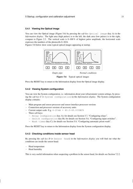
5.4.1 Viewing the Optical image<br />
You can view the Optical image (Figure 5.6) by <strong>pr</strong>essing the soft key Optical image (key A) in the<br />
In<strong>for</strong>mation display. The light area (high pulses) is to the left, the dark area (low pulses) is to the right,<br />
compare to Figure 2.2. The vertical scale is 0–100 % of highest pulse amplitude, the horizontal scale<br />
ex<strong>pr</strong>esses the numbers of the photocells 0–1024.<br />
Figures 5.6 below show some typical optical images appearing at startup.<br />
SCALED<br />
OPTICAL<br />
IMAGE<br />
TEST: 248.0<br />
30.2 ºC<br />
Endp: 11<br />
L): 30.5<br />
R(: 5.3<br />
HT: 20 ºC<br />
HH: 4 %<br />
SCALED<br />
OPTICAL<br />
IMAGE<br />
TEST: 133.6<br />
30.2 ºC<br />
Endp: 11<br />
L): 16.5<br />
R(: 30.3<br />
HT: 20 ºC<br />
HH: 4 %<br />
Slope<br />
Low concentration / No sample<br />
Slope<br />
Normal operation<br />
A B C D<br />
Empty pipe<br />
Figure 5.6<br />
A B C D<br />
Normal conditions<br />
Typical optical images<br />
Press the RESET key to return to the In<strong>for</strong>mation display from the Optical image display.<br />
5.4.2 Viewing System configuration<br />
You can view the System configuration, i.e. in<strong>for</strong>mation about your <strong>refractometer</strong> system settings, by <strong>pr</strong>essing<br />
the soft key C (= System configuration) in the In<strong>for</strong>mation display. The System configuration<br />
display contains:<br />
− Main <strong>pr</strong>ogram and sensor <strong>pr</strong>ocessor and sensor interface <strong>pr</strong>ocessor versions<br />
− Connection and <strong>pr</strong>ocessor versions of accessory units<br />
− Current output scale: E.g. 4–20 mA = 40.0–60.0 CONC%<br />
− Three soft keys:<br />
− Relay configuration (key A); <strong>for</strong> details see Section 5.7, “Configuring relays”.<br />
− Switch configuration (key B); <strong>for</strong> details see Section 5.6, “Configuring input switches”.<br />
− Wash times (key C); <strong>for</strong> details see Section 5.9, “Configuring automatic <strong>pr</strong>ism wash”.<br />
Press the RESET key to return to the In<strong>for</strong>mation display from the System configuration display.<br />
5.4.3 Checking conditions inside sensor head<br />
By <strong>pr</strong>essing the soft key D (= Sensor<br />
conditions are inside the sensor head:<br />
head) in the In<strong>for</strong>mation display you will find out what the<br />
− Head temperature<br />
− Head humidity<br />
This is very useful in<strong>for</strong>mation when suspecting a <strong>pr</strong>oblem in the sensor head, <strong>for</strong> details see Section 7.2.2.