instruction manual for inline refractometer pr-03 - K-Patents
instruction manual for inline refractometer pr-03 - K-Patents
instruction manual for inline refractometer pr-03 - K-Patents

You also want an ePaper? Increase the reach of your titles
YUMPU automatically turns print PDFs into web optimized ePapers that Google loves.
30 PR-<strong>03</strong> <strong>instruction</strong> <strong>manual</strong><br />
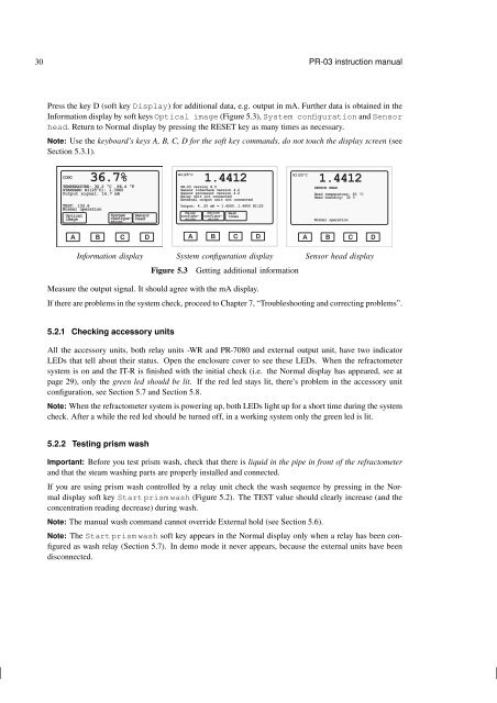
Press the key D (soft key Display) <strong>for</strong> additional data, e.g. output in mA. Further data is obtained in the<br />
In<strong>for</strong>mation display by soft keys Optical image (Figure 5.3), System configuration and Sensor<br />
head. Return to Normal display by <strong>pr</strong>essing the RESET key as many times as necessary.<br />
Note: Use the keyboard’s keys A, B, C, D <strong>for</strong> the soft key commands, do not touch the display screen (see<br />
Section 5.3.1).<br />
CONC<br />
36.7%<br />
TEMPERATURE: 30.2 °C 86.4 °F<br />
STANDARD RI(25°C): 1.3960<br />
Output signal: 16.7 mA<br />
TEST: 133.6<br />
Normal operation<br />
Optical<br />
image<br />
System Sensor<br />
configuration<br />
head<br />
RI(25ºC<br />
1.4412<br />
PR-<strong>03</strong> version 8.5<br />
Sensor interface version 4.0<br />
Sensor <strong>pr</strong>ocessor version 4.0<br />
Relay unit not connected<br />
External output unit not connected<br />
Output: 4..20 mA = 1.4260..1.4900 RI(25<br />
Relay<br />
configuration<br />
Switch<br />
configuration<br />
Wash<br />
times<br />
RI(25ºC<br />
1.4412<br />
SENSOR HEAD<br />
Head temperature: 20 ºC<br />
Head humidity: 32 %<br />
Normal operation<br />
A B C D<br />
A B C D<br />
A B C D<br />
In<strong>for</strong>mation display System configuration display Sensor head display<br />
Figure 5.3 Getting additional in<strong>for</strong>mation<br />
Measure the output signal. It should agree with the mA display.<br />
If there are <strong>pr</strong>oblems in the system check, <strong>pr</strong>oceed to Chapter 7, “Troubleshooting and correcting <strong>pr</strong>oblems”.<br />
5.2.1 Checking accessory units<br />
All the accessory units, both relay units -WR and PR-7080 and external output unit, have two indicator<br />
LEDs that tell about their status. Open the enclosure cover to see these LEDs. When the <strong>refractometer</strong><br />
system is on and the IT-R is finished with the initial check (i.e. the Normal display has appeared, see at<br />
page 29), only the green led should be lit. If the red led stays lit, there’s <strong>pr</strong>oblem in the accessory unit<br />
configuration, see Section 5.7 and Section 5.8.<br />
Note: When the <strong>refractometer</strong> system is powering up, both LEDs light up <strong>for</strong> a short time during the system<br />
check. After a while the red led should be turned off, in a working system only the green led is lit.<br />
5.2.2 Testing <strong>pr</strong>ism wash<br />
Important: Be<strong>for</strong>e you test <strong>pr</strong>ism wash, check that there is liquid in the pipe in front of the <strong>refractometer</strong><br />
and that the steam washing parts are <strong>pr</strong>operly installed and connected.<br />
If you are using <strong>pr</strong>ism wash controlled by a relay unit check the wash sequence by <strong>pr</strong>essing in the Normal<br />
display soft key Start <strong>pr</strong>ism wash (Figure 5.2). The TEST value should clearly increase (and the<br />
concentration reading decrease) during wash.<br />
Note: The <strong>manual</strong> wash command cannot override External hold (see Section 5.6).<br />
Note: The Start <strong>pr</strong>ism wash soft key appears in the Normal display only when a relay has been configured<br />
as wash relay (Section 5.7). In demo mode it never appears, because the external units have been<br />
disconnected.