
Create successful ePaper yourself
Turn your PDF publications into a flip-book with our unique Google optimized e-Paper software.
Free Damped Vibrations of Sandwich<br />
Shells of Revolution<br />
ALEKSANDR KORJAKIN, 1, * ROLANDS RIKARDS, 1 HOLM ALTENBACH 2<br />
AND ANDRIS CHATE 1<br />
1 Technical University Riga, Kalku iela 1, LV-1658, Riga, Latvia<br />
2 Martin-Luther-University Halle-Wittenberg, D-06099 Halle, Germany<br />
ABSTRACT: Using a zig-zag model the free damped vibrations of sandwich shells of<br />
revolution are investigated. As special cases the vibration analysis under consideration of<br />
damping of cylindrical, conical and spherical sandwich shells is performed. A specific<br />
sandwich shell finite element with 54 degrees of freedom is employed. Starting from<br />
the energy method the damping model is developed. Numerical examples for the free<br />
vibration analysis with damping based on the proposed finite element approach are<br />
discussed. Results for sandwich shells show a satisfactory agreement with various reference<br />
solutions.<br />
KEY WORDS: cylindrical shell, conical shell, spherical shell, sandwich structures, finite<br />
element analysis, free vibration, damping.<br />
INTRODUCTION<br />
DAMPING IS A significant dynamic parameter for vibration and sound control,<br />
dynamic stability, fatigue endurance and impact resistance. Many structural<br />
applications (large space structures, engine blades and high-speed machinery) require<br />
light weight and high dynamic performance. Therefore, a possible source of<br />
passive damping should add minimal parasitic weight and must be compatible<br />
with the structural configuration. Two potential damping sources satisfying the<br />
previous requirements are the introduction of constrained damping layers and the<br />
damping capacity of composites.<br />
Vibrational damping analysis of laminated composite beam and plates has been<br />
investigated by several authors [14,19,25,32,42]. The application to laminated<br />
*Author to whom correspondence should be addressed. E-mail: aleks@latnet.lv<br />
Journal of SANDWICH STRUCTURES AND MATERIALS, Vol. 3—July 2001<br />
171<br />
1530-7972/01/03 0171–26 $10.00/0 DOI: 10.1106/LB2E-22L4-7JA6-CAED<br />
© 2001 Technomic Publishing Co., Inc.<br />
Journal Online at http://techpub.metapress.com
172 ALEKSANDR KORJAKIN ET AL.<br />
shells is discussed, for example, in References [2,3,8,15,22,23,33,35,43,44,48].<br />
Though the damping characteristics of laminated composite structures have been<br />
studied extensively, studies of sandwich composite structures are limited. The<br />
analysis of sandwich beams and constrained layer damping in beams has been performed<br />
in Reference [9]. A three-layered beam theory was employed where the<br />
continuity of the displacements and the transverse shear stresses is satisfied at the<br />
interfaces. The energy method is used to derive the governing equations of motion<br />
for transverse vibrations of curved sandwich beams [46]. Flexural vibrations of<br />
viscoelastic damped sandwich plates has been analyzed in Reference [17]. A finite<br />
element analysis associated with an asymptotic solution method for the harmonic<br />
flexural vibrations was proposed. The finite element method was employed for the<br />
analysis of the harmonic response of damped three-layer plates in Reference [20].<br />
General non-linear equations of motion of viscoelastic damped sandwich plates<br />
and cylindrical panels were derived with the help of the principle of virtual work in<br />
Reference [49]. A special finite element approach was developed in Reference<br />
[36] to study the vibration and damping characteristics of three-layered conical<br />
shells with a viscoelastic core. A finite element based on the discrete layer theory<br />
and taking into account the shear deformations was used for analysis of spherical<br />
shells with a viscoelastic core in Reference [15]. Damping properties of three-layered<br />
shallow spherical shells have been studied in Reference [33]. Expressing the<br />
in-plane displacements in terms of auxiliary functions, the general solution of the<br />
equations of motion for non-axisymmetric modes was given in terms of Bessel’s<br />
functions.<br />
Different shell and plate theories can be used to analyze the sandwich structures.<br />
Good results can be obtained employing the so called zig-zag theories. In<br />
Reference [10] a multilayered plate element is proposed which meets computational<br />
requirements and includes both the zig-zag distribution along the thickness<br />
coordinate of the in-plane displacements and the interlaminar continuity for the<br />
transverse shear stresses. A simple layerwise higher-order zig-zag model is proposed<br />
for the bending of laminated composite plates. The model accounts for cubic<br />
variation of the transverse shear stresses across the laminate with zero values at<br />
the free surface [27]. A beam finite element based on a discrete layer laminated<br />
beam theory with the sublaminate first-order zig-zag kinematic assumptions<br />
is presented and assessed for thick and thin laminated beams [50]. Authors<br />
have used a modified form of DiSciuva’s linear zig-zag laminate kinematics, in<br />
which continuity interfacial transverse shear stresses are satisfied identically. A<br />
computationally efficient finite-element formulation for linear and non-linear<br />
analysis of flat sandwich panels is presented in Reference [11]. Mechanical accuracy<br />
is acquired by allowing a zig-zag in-plane displacement field in the thickness<br />
direction and by fulfilling interlaminate equilibrium at the interface between the<br />
core and skins for the transverse shear stress components. A high accuracy for prediction<br />
of stresses can be obtained employing a higher-order zig-zag theory [6].
Free Damped Vibrations of Sandwich Shells of Revolution 173<br />
The vibration and damping analysis of sandwich shells has not been attempted<br />
so far and it is a subject of the present investigation. The natural frequencies and<br />
the loss factors of cylindrical, conical and spherical shells are calculated. A sandwich<br />
shell finite element based on the zig-zag model and described in Reference<br />
[12] is used for the dynamic analysis with damping. The energy method (EM) is<br />
employed to model the damping. The background of the EM is in finding the energy<br />
dissipated in a natural mode by adding up the contributions from the individual<br />
components of deformation. Such approach has been used by several authors,<br />
for example, in References [1,8,29,51]. The EM has been used for damping analysis<br />
of laminated plates [40]. The present paper is an extension of a similar investigation<br />
in the case of laminated shells presented in Reference [26].<br />
Governing Equations<br />
THEORETICAL BACKGROUND<br />
Considering a composite sandwich shell of uniform moderate thickness h with<br />
three anisotropic laminae, each of them may be arbitrarily oriented. The influence<br />
of the interphases between the laminae is neglected that means rigid connection<br />
between the layers. In addition, in the numerical analysis the typical sandwich assumptions<br />
(soft core, the thickness of the outer layers is much thinner in comparison<br />
with the core thickness) are taken into account.<br />
Displacements<br />
The kinematic equations for the first-order shear deformation theory (FOSDT)<br />
including the drilling rotation of the normal can be obtained from three-dimensional<br />
equations of the theory of elasticity using the Taylor series approximation of<br />
the vector of position function in the deformed state with respect to the coordinate<br />
x 3 (see, for example, References [7,39,41]).<br />
Let us introduce curvilinear coordinates x i ={x α ,x 3 } on the midsurface of the<br />
shell in the initial state which is defined by the triad {a α , a 3 }. The use of Greek indices<br />
means the values 1, 2. The unit vector a 3 denotes the normal to the middle<br />
surface of the shell. Curvilinear coordinates X i ={X α ,X 3 } are related to the deformed<br />
state which is defined by the triad {A α ,A 3 }. In the deformed state the vector<br />
A 3 may not be perpendicular to the midsurface of the shell.<br />
The representation of the displacement vector u of an arbitrary point of the shell<br />
with respect to the first-order approximation is<br />
α α α<br />
3 = + 3<br />
u( x , x ) v( x ) x (<br />
x )<br />
(1)<br />
Here v is the displacement vector of the midsurface and denotes the vector of
174 ALEKSANDR KORJAKIN ET AL.<br />
rotations at the midsurface<br />
= A −a<br />
3 3<br />
(2)<br />
In Equation (1) the vectors v and have three components, respectively<br />
α<br />
α<br />
3,<br />
α 3<br />
v= v a + wa = γ a + wa<br />
α<br />
(3)<br />
In this sense, the FOSDT is characterized by 6 independent degrees of freedom<br />
(FOSDT-6). The FOSDT version with five degrees of freedom (FOSDT-5) is usually<br />
used. The reasons for such limitation is the deformability of the thin-walled<br />
structure even in the case of moderate thickness: the magnitude of the assumed<br />
drilling of the normal is much smaller in comparison with the other two rotations.<br />
So in the case of the FOSDT-5 we assume γ = 0. For shells of revolution in this case<br />
the displacements u, v, and w in the x (meridian), ϕ (circumferential) and x 3 (normal,<br />
outward from the reference surface of the shell) directions at any point are expressed<br />
through the following approximations [31]:<br />
ux ( , ϕ , x, t) = u( x, ϕ , t) + xγ ( x, ϕ, t)<br />
3 0 3<br />
vx ( , ϕ , x, t) = v( x, ϕ , t) + xγ ( x, ϕ, t)<br />
3 0 3<br />
wx (, ϕ , x,) t = w(, xϕ,)<br />
t<br />
3 0<br />
x<br />
ϕ<br />
(4)<br />
where u 0 , v 0 , w 0 are the displacement components at the reference surface<br />
(midsurface) and γ x , γ ϕ are the rotations of the normal associated with the transverse<br />
shear deformations. Below the index “0” will be omitted. The approximations,<br />
Equation (4), are similar to Timoshenko’s proposal in the beam theory [45]<br />
and the analogue in the plate theory [18,30].<br />
STRAIN-DISPLACEMENT RELATIONS<br />
The displacements of an arbitrary point of the shell continuum is approximated<br />
by two vectors. Therefore, the displacement field of the shell in the FOSDT-6 including<br />
extension of the normal is represented by six unknown functions—three<br />
displacements (v α ,w) and three rotations (γ α ,γ). These quantities are functions of<br />
the shell middle surface coordinates x α only. From these displacements and rotations<br />
the two-dimensional strains can be obtained. The three-dimensional Green’s<br />
strain tensor in the linear case is given by Reference [16,41].<br />
2e ij = u, i ⋅ g j + u,<br />
j ⋅g<br />
i<br />
(5)<br />
Here (...), i denotes differentiation with respect to the coordinates x i , the dot means<br />
scalar product and g i is a triad of vectors for coordinates x i on the surfaces<br />
(x 3 = const) parallel to the middle surface of the shell. For these coordinates the
Free Damped Vibrations of Sandwich Shells of Revolution 175<br />
components of the metric tensor are given by g ij = g i ⋅ g j . With respect to Equation<br />
(1) from Equation (5) the kinematic equations for the strains in the shell can be deduced<br />
[41]:<br />
2<br />
αβ =Ω αβ + 3χ αβ + 3Φ αβ, 2 α3 = 2Ω α3 + 3κα3<br />
e x x e x<br />
(6)<br />
with<br />
and<br />
2 Ω = ε +ε , 2χ =κ +κ<br />
αβ αβ βα αβ αβ βα<br />
λ λ<br />
αβ bk α λβ bk β λα α3<br />
α α<br />
2 Φ = − − , 2Ω = γ +Ψ<br />
λ<br />
α3<br />
α bα λ<br />
κ =ϕ − γ<br />
λ<br />
αβ αβ αβ αβ αβ α λβ αβ αβ αβ<br />
ε = v −b w, κ = k −b ε , k = γ −b<br />
γ<br />
λ<br />
λ<br />
α α α λ α α α λ<br />
Ψ = w, + b v , ϕ = γ , + b γ<br />
(7)<br />
(8)<br />
Here (...) α denotes the covariant differentiation in the metric characterized by the<br />
fundamental tensor components of the midsurface a αβ = a α ⋅ a β , and b αβ are the curvature<br />
tensor components of the midsurface. All quantities in the Equations (7)<br />
and (8) depend on x α only. Neglecting the strains Φ αβ and κ α3 in Equations (6) the<br />
kinematics equations can be simplified:<br />
e =Ω + x χ , 2e<br />
= 2Ω =γ +Ψ<br />
αβ αβ 3 αβ α3 α3<br />
α α<br />
(9)<br />
It should be noted that the strains Φ αβ and κ α3 can be taken into account in the finite<br />
element analysis of the shell, since the number of unknown functions is the<br />
same—six. However, even for shallow shells, the influence of these strains is significant.<br />
Therefore, for simplicity these terms are hereafter omitted.<br />
For the analysis of shells of various shapes it is more convenient to use orthogonal<br />
coordinates, which conicide with the directions of principal curvatures. In this<br />
case the metric properties of the coordinate system associated with the midsurface<br />
of the shell are characterized by the Lamé’s coefficients A 1 and A 2 . These coefficients<br />
are connected with the components of the fundamental tensor of the<br />
midsurface:<br />
a<br />
αβ<br />
2<br />
⎡a11 0 ⎤ ⎡A<br />
1 0 ⎤<br />
= ⎢<br />
0 a<br />
⎥ = ⎢ ⎥<br />
2<br />
⎣ 22 ⎦ ⎢⎣<br />
0 A2<br />
⎥⎦<br />
(10)<br />
The kinematics, Equations (7) and (8), in orthogonal coordinates of principal cur-
176 ALEKSANDR KORJAKIN ET AL.<br />
vatures are given by (indices of the physical components of tensors are given in parentheses)<br />
[41]:<br />
1 ∂v 1 ∂A Ω = + v − b w , (1↔2)<br />
(1) 1<br />
(11) 1 2 (2) (11)<br />
A1 ∂x<br />
A1A2<br />
∂x<br />
1 ∂v<br />
1 ∂A<br />
1 ∂v<br />
1<br />
2Ω = − + −<br />
∂A<br />
(1) 2 (2)<br />
1<br />
(12) v<br />
2 1 (2) v<br />
1 2 (1)<br />
A2 ∂x A1A2 ∂x A1 ∂x A1A2<br />
∂x<br />
1 ∂γ 1 ∂A<br />
χ = + γ<br />
(1) 1<br />
(11) 1 2 (2)<br />
A1 ∂x<br />
A1A2<br />
∂x<br />
⎛ 1 ∂v<br />
1 ∂A<br />
⎞<br />
−b γ − b + v −b w⎟, (1↔2)<br />
⎠<br />
(1) 1<br />
(11) (11) ⎜ 1 2 (2) (11)<br />
⎝ A1 ∂x<br />
A1A2<br />
∂x<br />
(11)<br />
1 ∂γ 1 ∂A<br />
1 ∂γ 1 ∂A<br />
2χ = + γ + − γ<br />
(1) 2 (2)<br />
1<br />
(12) 2 1 (2) 1 2 (1)<br />
A2 ∂x A1A2 ∂x A1 ∂x A1A2<br />
∂x<br />
⎛ 1 ∂v<br />
1 ∂A<br />
⎞ ⎛ 1 ∂v<br />
1 ∂A<br />
⎞<br />
−b ⎜ − v ⎟ −b ⎜ − v<br />
⎝ ⎠ ⎝<br />
⎟<br />
⎠<br />
(1) 2 (2)<br />
1<br />
(11) 2 1 (2) (22) 1 2 (1)<br />
A2 ∂x A1A2 ∂x A1 ∂x A1A2<br />
∂x<br />
1 ∂w 2 Ω = γ + + b v , (1↔2)<br />
(13) (1) 1 (11) (1)<br />
A1<br />
∂x<br />
Here, the notations v (1) = u, v (2) = v are used for the physical components of the displacements.<br />
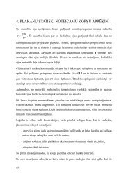
For shells of revolution it is convenient to use the coordinates x 1 = α, x 2 = ϕ (see<br />
Figure 1).<br />
In this case the curvature tensor is given by:<br />
b<br />
αβ<br />
⎡ 1 ⎤<br />
⎢−<br />
0<br />
R ⎥<br />
1<br />
= ⎢<br />
⎥<br />
⎢ sin α ⎥<br />
⎢ 0 − ⎥<br />
⎣ r ⎦<br />
(12)<br />
The Lamé’s coefficients of a shell of revolution are A 1 = R 1 and A 2 = r, where the radii<br />
can be functions of the meridian coordinate, r = r(α) and R 1 = R 1 (α). From these<br />
expressions the kinematic equations for various shaped shells of revolution can be<br />
obtained. Thus, the general strain-displacement relations for cylindrical shells<br />
(see Figure 2) [39] are
Free Damped Vibrations of Sandwich Shells of Revolution 177<br />
Figure 1. Geometry of a shell of revolution.<br />
Figure 2. Geometry of the sandwich cylindrical shell.
178 ALEKSANDR KORJAKIN ET AL.<br />
∂u<br />
∂γ x<br />
ε xx = + x3 =Ω xx + x3χxx<br />
∂x<br />
∂x<br />
1 ⎛ ∂v<br />
⎞ x ∂γ<br />
ε = + + =Ω + χ<br />
R⎝<br />
⎜<br />
∂ϕ ⎠<br />
⎟<br />
R ∂ϕ<br />
3 ϕ<br />
ϕϕ w<br />
ϕϕ x3<br />
ϕϕ<br />
1 ∂u<br />
∂v<br />
⎛ 1 ∂γ ∂γ ⎞<br />
γ = + + + = Ω + χ<br />
R ∂ϕ ∂x ⎜<br />
⎝R ∂ϕ ∂x<br />
⎟<br />
⎠<br />
x ϕ<br />
xϕ x3 2 xϕ 2x3<br />
xϕ<br />
∂w<br />
γ xx = γ 2<br />
3 x + = Ωxx<br />
3<br />
∂x<br />
1 ⎛∂w<br />
⎞<br />
γ = γ + − v = 2Ω<br />
R<br />
⎜<br />
⎝∂ϕ<br />
⎟<br />
⎠<br />
ϕx3 ϕ ϕx3<br />
(13)<br />
where R is the reference surface radius of the cylinder, ε xx , ε ϕϕ are the normal<br />
strains, and γ xϕ , γ xx , γ<br />
3 ϕx<br />
are the shear strains. In addition, Ω<br />
3<br />
xx , Ω ϕϕ , Ω xϕ denote<br />
the membrane strains, χ xx , χ ϕϕ , χ xϕ are the bending strains and Ω xx , Ω<br />
3 ϕx<br />
are the<br />
3<br />
transverse shear strains in the reference surface, respectively. The general<br />
strain-displacement relations for conical shells (see Figure 3) are given by<br />
∂u<br />
∂γ<br />
ε = + =Ω + χ<br />
∂x<br />
∂x<br />
x<br />
xx x3 xx x3<br />
xx<br />
1 ⎛ ∂v<br />
⎞<br />
ε ϕϕ = usin<br />
wcos<br />
r<br />
⎜ β+ + β<br />
⎝ ∂ϕ<br />
⎟<br />
⎠<br />
x3<br />
⎡ ∂γ ϕ cosβ⎛<br />
∂v<br />
⎞⎤<br />
+ ⎢γx<br />
sinβ+ + + usinβ+ wcosβ ⎥ =Ω ϕϕ + x3χ<br />
r<br />
∂ϕ r<br />
⎜<br />
⎝∂ϕ<br />
⎟<br />
⎣<br />
⎠⎦<br />
ϕϕ<br />
1 ∂u ∂v v<br />
γ xϕ<br />
= + − sinβ<br />
r ∂ϕ ∂x r<br />
⎛1∂γ<br />
∂γ<br />
x ϕ γ ϕ cosβ∂v⎞<br />
+ x3⎜<br />
+ − sinβ+ = 2Ω xϕ<br />
+ 2x3χ<br />
⎝r ∂ϕ ∂x r r ∂x<br />
⎟<br />
⎠<br />
xϕ<br />
(14)<br />
∂w<br />
= 2Ω<br />
x<br />
γ xx = γ<br />
3 x + xx ∂<br />
3<br />
1 ⎛∂w<br />
⎞<br />
γ = γ + − v cosβ = 2Ω<br />
r<br />
⎜<br />
⎝∂ϕ<br />
⎟<br />
⎠<br />
ϕx3 ϕ ϕx3<br />
where r = r(z) is the reference surface radius and β is the semi-vertex angle. The<br />
generalstrain-displacement relations for spherical shell (see Figure 4) are givenby
Free Damped Vibrations of Sandwich Shells of Revolution 179<br />
Figure 3. Geometry of the sandwich conical shell.<br />
Figure 4. Geometry of the sandwich spherical shell.
180 ALEKSANDR KORJAKIN ET AL.<br />
1 ⎛∂u<br />
⎞ x ⎡∂γ<br />
1 ⎛∂u<br />
⎞⎤<br />
ε = + + + + =Ω + χ<br />
R⎝∂α ⎠ R<br />
⎢<br />
∂α R⎝∂α<br />
⎠⎥<br />
⎣<br />
⎦<br />
3 α<br />
αα ⎜ w⎟ ⎜ w⎟<br />
αα x3<br />
αα<br />
1 ⎛ ∂v<br />
⎞<br />
ε ϕϕ = ucosα+ + wsin<br />
α<br />
Rsinα<br />
⎜<br />
⎝ ∂ϕ<br />
⎟<br />
⎠<br />
x ⎡<br />
3<br />
⎛ ∂γ ϕ ⎞ 1 ⎛ ∂v<br />
⎞⎤<br />
+ ⎢ γα<br />
cosα+ +γsin α + ucosα+ + wsin<br />
α ⎥<br />
Rsinα ⎜ ⎟<br />
R<br />
⎜ ⎟<br />
⎣⎝ ∂ϕ ⎠ ⎝ ∂ϕ ⎠⎦<br />
=Ω + x χ<br />
ϕϕ<br />
3<br />
ϕϕ<br />
1 ⎛∂u<br />
⎞ 1 ∂v<br />
γ αϕ = −v<br />
cosα +<br />
Rsinα ⎜<br />
⎝∂ϕ ⎟<br />
⎠ R ∂α<br />
x3<br />
⎡ 1 ⎛∂γ α ⎞ ∂γ ϕ 1 ⎛∂u⎞<br />
1 ∂v⎤<br />
+ ⎢<br />
ϕ cos<br />
R sin<br />
⎜ −γ α ⎟ + +<br />
Rsin<br />
⎜ ⎟ + ⎥<br />
⎣ α ⎝ ∂ϕ ⎠ ∂α α ⎝∂ϕ⎠<br />
R ∂α ⎦<br />
= 2Ω + 2x<br />
χ<br />
αϕ<br />
3<br />
αϕ<br />
(15)<br />
1 ⎛∂w<br />
⎞<br />
γ = γ + ⎜ − u ⎟ = 2Ω<br />
R ⎝∂α<br />
⎠<br />
αx3 α αx3<br />
1 ⎛∂w<br />
⎞<br />
γ = γ + − v sinα = 2Ω<br />
Rsinα<br />
⎜<br />
⎝∂ϕ<br />
⎟<br />
⎠<br />
ϕx3 ϕ ϕx3<br />
where R is the radius of the reference surface and α is the coordinate in the meridian<br />
direction of spherical shell.<br />
CONSTITUTIVE EQUATIONS<br />
Let us discuss the constitutive equations of sandwich shells. The constitutive<br />
equations related to the global shell coordinate system are given, for instance, in<br />
References [5,28,37]. The stress-strain relations for the anisotropic layers of the<br />
shell are<br />
=<br />
L<br />
Ae<br />
(16)<br />
where A L is the transformed reduced stiffness matrix of the Lth layer in the shell<br />
reference axes (L = 1,2,3).<br />
For mathematical modelling purposes the individual layer is considered to be<br />
homogeneous and orthotropic while the laminate is heterogeneous through the<br />
thickness and generally anisotropic. Therefore, the constitutive equations for the
Free Damped Vibrations of Sandwich Shells of Revolution 181<br />
sandwich shell can be split into two parts:<br />
<br />
= D e , = D e<br />
NM NM NM Q Q Q<br />
(17)<br />
with<br />
<br />
e<br />
T<br />
NM xx ϕϕ xϕ xx ϕϕ xϕ<br />
<br />
= { N , N , N , M , M , M }<br />
T<br />
Q<br />
= { Q , Q }<br />
x<br />
T<br />
NM xx ϕϕ xϕ xx ϕϕ xϕ<br />
= { Ω , Ω ,2 Ω , χ , χ ,2 χ }<br />
T<br />
Q<br />
e<br />
ϕ<br />
= {2 Ω , 2 Ω }<br />
x3 ϕ3<br />
(18)<br />
and<br />
D<br />
NM<br />
⎡Q11 Q12 Q16 B11 B12 B16<br />
⎤<br />
⎢<br />
Q12 Q22 Q26 B12 B22 B<br />
⎥<br />
⎢<br />
26 ⎥<br />
⎢Q16 Q26 Q66 B16 B26 B66<br />
⎥<br />
= ⎢ ⎥<br />
⎢B11 B12 B16 D11 D12 D16<br />
⎥<br />
⎢B 12 B22 B26 D12 D22 D ⎥<br />
26<br />
⎢<br />
⎥<br />
⎢⎣B16 B26 B66 D16 D26 D66<br />
⎥⎦<br />
(19)<br />
D<br />
Q<br />
⎡<br />
2<br />
kQ 5 55 kkQ ⎤<br />
4 5 45<br />
= ⎢ ⎥<br />
2<br />
⎢⎣kkQ<br />
4 5 45 kQ 4 44⎥⎦<br />
(20)<br />
The components of the in-plane (membrane), the coupling and the out-of-plane<br />
plate (bending and torsion) stiffness matrices Q ij , B ij , D ij , i, j = 1,2,6 are defined in<br />
Reference [26]. The shear correction coefficients k4 2 , k5 2 can be calculated by difference<br />
approaches [47]. Here the approach based on averaging of transverse shear<br />
strain complementary energy and outlined in Reference [40] is used.<br />
VARIATIONAL FORMULATION<br />
The governing differential equations of motion can be derived by using the<br />
Hamilton’s principle [39]:<br />
∫<br />
t2<br />
t1<br />
( δU−δT −δ W ) dt = 0<br />
e<br />
(21)<br />
where δU, δT, δW e are the variations of the strain energy, the kinetic energy and the<br />
work of external forces, respectively, t denotes the time. The strain energy for the
182 ALEKSANDR KORJAKIN ET AL.<br />
sandwich shell is given by<br />
1 T<br />
T<br />
U = ∫ ( e D e + e D e ) dA<br />
2 Ashell<br />
NM NM NM Q Q Q shell<br />
(22)<br />
and the kinetic energy can be written in the form<br />
T 1<br />
p T<br />
= ∫ ∫ uu ̇ ̇ dx dA<br />
2 Ashell<br />
h<br />
3<br />
shell<br />
(23)<br />
here ρ is the mass density, (… • ) denotes differentiation with respect to time and<br />
u T ={v T , T }. A shell is the surface area of the shell and h is the thickness of the shell.<br />
Substituting Equation (1) into Equation (23) one can obtain [41]<br />
1<br />
T = ∫ [ ρ0vv ̇⋅ ̇+ρ1( v̇⋅ ̇ + ̇⋅ v̇) +ρ2γ⋅γ<br />
̇ ̇]<br />
dA<br />
2 Ashell<br />
(24)<br />
Here ρ i , i = 0,1,2 are the generalized densities of the shell, v T ={v (1) ,v (2) ,w} and<br />
T ={γ (1) ,γ (2) ,γ}. For the shallow shell Equation (24) can be expressed as [41]<br />
3<br />
∑<br />
ρ = ρ [ x −x<br />
]<br />
0 k 3( k+<br />
1) 3( k)<br />
k=<br />
1<br />
1<br />
3<br />
1 2 2<br />
∑ k x3( k+<br />
1) x3( k)<br />
2<br />
k=<br />
1<br />
2<br />
3<br />
1 3 3<br />
∑ k x3( k+<br />
1) x3( k)<br />
3<br />
k=<br />
1<br />
ρ = ρ [ − ]<br />
ρ = ρ [ − ]<br />
(25)<br />
ρ k is the density of the Lth layer. In the case of applied distributed load at the shell<br />
midsurface it is necessary to define the work of external forces W e [41].<br />
Finite Element Formulation<br />
The finite element employed for the analysis of the present problem is the sandwich<br />
shell finite element CLW54 [12] based on the zig-zag model (see Figure 5).<br />
This model allows performance of more precise free vibration analysis for sandwich<br />
structures in comparison with the multilayered shell finite element presented<br />
in Reference [38]. This is important for sandwich structures with thick core layer<br />
and significant differences in elastic moduli between outer layers and core. In the<br />
shell finite element CLW54 each layer is considered as a simple laminated composite<br />
shell finite element. It is a triangular finite element (second order<br />
polynominal shape functions are used) with six nodes. In each nodal point there
Free Damped Vibrations of Sandwich Shells of Revolution 183<br />
Figure 5. Kinematical assumptions for sandwich finite element in the thickness direction.<br />
are five degrees of freedom: three displacements (u, v, w) and two rotations (γ x , γ ϕ ),<br />
where u, v and w are displacements in the directions of reference axes x 1 , x 2 and x 3<br />
of the shell. Stiffness and mass matrices of this finite element have been derived in<br />
detail in Reference [38]. Using the displacement continuity conditions between<br />
layers, the sandwich finite element was developed. A similar approach was used<br />
for developing the sandwich plate finite element PLW54 [12].<br />
The sandwich shell finite element has 54 independent degrees of freedom. For<br />
the bottom layer (six nodal points) in every node there are three displacements<br />
( 1) ( 1) ( 1)<br />
( ) ( )<br />
( u0<br />
, v0<br />
, w0<br />
) and two rotations ( γ<br />
1 , γ<br />
2 ),<br />
x1 x2<br />
while for the top layer there are<br />
two displacements ( ( 3 ) , ( 3<br />
u v<br />
) ) and two rotations ( γ<br />
( 3) , γ<br />
( 3)<br />
) only.<br />
0<br />
0<br />
x1 x2<br />
DISPLACEMENT REPRESENTATION<br />
In each layer of the sandwich structure the kinematics, Equation (4), are assumed.<br />
As the reference surface the midsurface of the bottom layer is used and displacements<br />
and rotations of all layers are defined in the coordinates of midsurface<br />
of the bottom surface. For the first (bottom) layer the displacements can be ex-
184 ALEKSANDR KORJAKIN ET AL.<br />
pressed as follows:<br />
(1) (1) (1) (1)<br />
1 3 x , 1 3 ϕ , 1<br />
u = u + x γ v = v + x γ w = w<br />
(26)<br />
For the third (top) layer the displacements are represented as<br />
(3) (3) (3) (3)<br />
3 3 x , 3 3 ϕ , 3<br />
u = u + x γ v = v + x γ w = w<br />
(27)<br />
The displacement continuity conditions between the layers of the sandwich shell<br />
are given as<br />
u = u , v = v , w = w ( i = 1,2)<br />
i i+ 1 i i+ 1 i i+<br />
1<br />
(28)<br />
Taking into account these displacement continuity conditions, the displacements<br />
for the core can be presented as<br />
(2) (2) (2) (2)<br />
2 3 x , 2 3 ϕ , 2<br />
u = u + x γ v = v + x γ w = w<br />
(29)<br />
And the variables u (2) , v (2) , γ<br />
( 1) ( 1) ( 3) ( )<br />
γ , γ , γ , γ<br />
3 as follows:<br />
x<br />
ϕ<br />
x<br />
ϕ<br />
( 2 ) ( )<br />
x γ 2<br />
ϕ<br />
and depend from u (1) , v (1) , u (3) , v (3) ,<br />
(2) (1) (3) (1) (3)<br />
=+ 1 + 2 + 3γx<br />
− 3γx<br />
u Fu F u F F<br />
(2) (1) (3) (1) (3)<br />
x Fu 4 Fu 4 F2 x F1<br />
x<br />
γ = − + + γ + γ<br />
(2) (1) (3) (1) (3)<br />
=+ 1 + 2 + 3γϕ<br />
− 3γϕ<br />
v Fv F v F F<br />
(2) (1) (3) (1) (3)<br />
ϕ Fv 4 Fv 4 F2 ϕ F1<br />
ϕ<br />
γ = + − − γ − γ<br />
(30)<br />
where<br />
(1) (1)<br />
h<br />
h<br />
1<br />
1 = 1 + 2, 2 = − ,<br />
(2) 3 = 1 , 4 =<br />
(2)<br />
F F F F F F<br />
2h<br />
2<br />
The displacement field of the sandwich shell can be described by vector components<br />
h<br />
u<br />
T<br />
(1) (1) (1) (1) (1) (3) (3) (3) (3)<br />
0 0 0 x ϕ 0 0 x ϕ<br />
= { u , v , w , γ , γ , u , v , γ , γ }<br />
(31)<br />
For the case of a six nodal point finite element (with 9 degrees of freedom per<br />
node), the displacement variation over the finite element can be described by
Free Damped Vibrations of Sandwich Shells of Revolution 185<br />
u= N = [ N , N ,..., N ] =∑ N<br />
() e 1 2 6 () e i i<br />
i= 1<br />
6<br />
(32)<br />
where<br />
T<br />
() e = 1 2 6<br />
{ , ,..., }<br />
(33)<br />
are generalised displacements of the finite element and<br />
<br />
T (1) (1) (1) (1) (1) (3) (3) (3) (3)<br />
i = u0 v<br />
i 0<br />
w<br />
i 0 γ i x γ i ϕ<br />
u<br />
i 0<br />
v<br />
i 0<br />
γ i x<br />
γ<br />
i ϕi<br />
{ , , , , , , , , }<br />
(34)<br />
is the vector of the displacement parameters at node i. Here<br />
N<br />
i<br />
= Ni<br />
I<br />
9<br />
(35)<br />
where N i are the shape functions for node i expressed in terms of local triangular<br />
coordinate system (L 1 ,L 2 ,L 3 ) of the finite element and I 9 istheunit9×9matrix.<br />
UNDAMPED VIBRATION<br />
The Hamilton’s principle given by Equation (21) is discretised as<br />
∫<br />
N<br />
t e<br />
2<br />
t1<br />
∑( δUl −δTl −δ Wel) dt = 0<br />
l=<br />
1<br />
(36)<br />
where N e is the total number of finite elements and the subscript l represents the<br />
contribution of the lth element. Equation (36) can be expressed in terms of the displacements<br />
and rotation angles (u 0 ,v 0 ,w 0 ,γ x ,γ ϕ ). Following the standard finite element<br />
technique, we obtain the discretised equations in terms of nodal degrees of<br />
freedom x:<br />
Mẋ̇ + Kx = F<br />
(37)<br />
where M, K, x, F are the global mass and stiffness matrices, the displacement and<br />
load vector, respectively. For free vibration problems F = 0 and Equation (37) becomes<br />
2<br />
( K− M)<br />
=<br />
0<br />
(38)<br />
where is the natural frequency and is the corresponding mode shape of the<br />
structure.
186 ALEKSANDR KORJAKIN ET AL.<br />
Damping Models<br />
ENERGY METHOD<br />
In this model a specific damping capacity (SDC) ψ is introduced as a parameter<br />
which characterises the damping properties of the material or structure [19]:<br />
∆U<br />
ψ = 2πη=<br />
(39)<br />
U<br />
where η is the loss factor, ∆U is the strain energy dissipated during one cycle of vibration,<br />
and U is the total strain energy of the entire of sandwich shell at maximum<br />
of the displacement during the same cycle. Following the definition of the SDC,<br />
the total energy dissipation can be expressed by [19]<br />
3<br />
∑<br />
∆ U = ∆U<br />
L=<br />
1<br />
( L)<br />
(40)<br />
where ∆U (L) is the strain energy dissipated in the Lth layer<br />
( L)<br />
1 ZL<br />
T L<br />
∆ U = { 0} [ ] { 0}<br />
2<br />
∫∫ ε C dzdA<br />
A Z<br />
ψ ε<br />
L−1<br />
(41)<br />
Here<br />
⎡<br />
L L L L<br />
ψ11C11 ψ12C12<br />
0 0 0 ⎤<br />
⎢<br />
⎥<br />
L L L L<br />
⎢ψ21C21 ψ22C22<br />
0 0 0 ⎥<br />
L ⎢<br />
[ ]<br />
L L<br />
⎥<br />
Cψ<br />
= ⎢ 0 0 ψ44C44<br />
0 0 ⎥<br />
⎢<br />
L L ⎥<br />
⎢<br />
0 0 0 ψ55C55<br />
0<br />
⎥<br />
⎢<br />
L L<br />
0 0 0 0 66C<br />
⎥<br />
⎣<br />
ψ 66 ⎦<br />
(42)<br />
and ψ L ij are the SDC of the corresponding layer [19]. WhereC L ij are the plane-stress<br />
reduced components of the Lth layer in the material axis (1,2,3) and {ε 0 } T =<br />
{ε 1 ,ε 2 ,ε 23 ,ε 13 ,ε 12 } are strain components in the same axis. Using the energy<br />
method it is assumed that the natural frequencies and modes of the damped system<br />
are the same as those of the associated undamped system. This expression is obtained<br />
for general case when damping matrix is not symmetrical. It is assumed that<br />
L L<br />
ψ12 = ψ21<br />
in our algorithm. Solving the eigenproblem (38), the SDC to the nth<br />
mode can be calculated by<br />
ψ<br />
T<br />
∆U<br />
( n) H( n)<br />
( n) = 2πη ( n)<br />
= =<br />
U<br />
T<br />
( n) K( n)<br />
(43)
Free Damped Vibrations of Sandwich Shells of Revolution 187<br />
where η (n) is the modal loss factor and H is the global damping matrix for shell. A<br />
detailed description of global damping matrix H is given in Reference [12].<br />
NUMERICAL EXAMPLES<br />
In the examples the symmetry of the cross section is assumed. So we have the<br />
same isotropic material properties for the inner and outer layer, the core is made<br />
from orthotropic material. For the inner and outer layer characteristics the index t<br />
is used; for the core, c.<br />
Free Undamped Vibration of a Sandwich Conical Shell<br />
The first problem considered is a conical sandwich shell with clamped-clamped<br />
boundary conditions. The geometry of the shell is characterised by the following<br />
quantities: the thickness of outer layers h t = 0.000535 m and core h c = 0.00762 m,<br />
the radius of the cone at its small end R = 0.5702 m, the semi-vertex angle<br />
β = 5.07°, the meridional length of the cone L = 1.8415 m, Figure 6. The following<br />
properties of the material are assumed: outer layers from glass epoxy E t = 25.08<br />
GPa, ν t = 0.20, p t = 2800 kg/m 3 and inner layer form aluminium honeycomb E1 c =<br />
0.529 GPa,G12= c 0.2204 GPa,G13= c c c<br />
0.126 GPa, ν = ν = 0.2, ρ c = 36.80 kg/m 3 .<br />
12 13<br />
Figure 6. The sandwich conical shell.
188 ALEKSANDR KORJAKIN ET AL.<br />
Table 1. Natural frequencies f nm for a sandwich<br />
clamped-clamped conical shell.<br />
n m CLW54<br />
Ramesh and<br />
Ganesan (1993)<br />
Wilkins<br />
(1970)<br />
1 1 — 299.9 —<br />
2 184.7 184.9 177.2<br />
3 127.4 128.3 126.0<br />
4 110.7 111.3 110.7<br />
5 127.0 127.3 126.7<br />
6 164.2 164.7 163.5<br />
7 212.7 213.8 212.3<br />
8 268.9 271.3 269.1<br />
2 1 — 521.0 —<br />
2 349.2 350.1 340.1<br />
3 250.0 252.3 254.3<br />
4 200.1 202.5 209.7<br />
5 188.0 190.2 197.7<br />
6 207.9 210.2 214.8<br />
7 250.4 252.9 254.5<br />
8 307.5 310.7 310.0<br />
The results for natural frequencies of sandwich conical shell obtained by using<br />
the presented finite element CLW54 and the results from the reference of [35,48]<br />
are shown in the Table 1. The values for modes m =1,n = 1 and m =1,n =2havenot<br />
been analyzed at this time due to a prohibitive amount of calculations.<br />
Vibration and Damping Analysis of<br />
Composite Sandwich Cylindrical Panel<br />
The free vibration frequencies and the corresponding loss factors are studied<br />
for a cylindrical panel under clamped conditions on the straight sides. The geometry<br />
of the panel is characterized by the following quantities: the thickness of<br />
the outer layers h t = 0.001 m and the thickness of core h c = 0.002; 0.004; 0.006; ...;<br />
0.018 m. The panel has the sizes 0.5 × 0.5 m in plane. The radius of the cylinder<br />
R = 0.5 m, Figure 7. The layers of the panel are made from materials with the<br />
following properties: for the aluminium outer layers, E t =70GPa;ν t = 0.20;<br />
p t = 2800 kg/m 3 ; and for the aluminium honeycomb core E1<br />
c = 0.529 GPa;<br />
G12 c = 0.2204 GPa;G13= c 0.126 GPa; ν c c<br />
12 = ν 23 = 0.2; ρ c = 280 kg/m 3 . The loss factor<br />
was assumed zero (η t = 0) for outer layers and η c = 0.4 for the core. The results obtained<br />
by the presented method for the first four natural frequencies and the corresponding<br />
loss factors of sandwich cylindrical panel are shown in Figure 8 and Figure<br />
9.
Free Damped Vibrations of Sandwich Shells of Revolution 189<br />
Figure 7. The sandwich cylindrical panel.<br />
Figure 8. Natural frequencies of the sandwich cylindrical panel for modes 1 – 1–1 – 4.
190 ALEKSANDR KORJAKIN ET AL.<br />
Figure 9. Modal loss factors of the sandwich cylindrical panel for modes 1 – 1–1 – 4.<br />
Vibration and Damping Analysis of a<br />
Composite Sandwich Conical Shell<br />
A three-layered composite conical shell has been considered. The shell has two<br />
variants of boundary conditions: clamped-clamped and simply supported-simply<br />
supported from both sides. The following geometric characteristics are presented:<br />
the thickness of outer layers h t = 0.0005 m and core h c = 0.004, 0.005, 0.006, ...,<br />
0.012 m, the radius of the cone at its small end R = 0.27 m, the semi-vertex angle<br />
β = 7.0°, the meridional length of the cone L = 0.84 m, Figure 6. The layers are with<br />
the following properties of material: outer from glass epoxy E t = 25.0 GPa,<br />
ν t = 0.20, p t = 2800 kg/m 3 and inner from aluminium honeycomb E1 c =0.529 GPa,<br />
E2 c c c<br />
= 0.226 GPa, ν 12 = ν 23 = 0.2, ρ c = 36.80 kg/m 3 . The loss factor was assumed<br />
zero (η t = 0) for outer layers and η c = 0.4 for the core. The results for the natural frequencies<br />
and modal loss factors of sandwich conical shell with different core<br />
thickness obtained by using finite element CLW54 are presented in Figures 10 and<br />
11 for clamped-clamped and Figures 12 and 13 for simply supported boundary<br />
conditions.<br />
Vibration and Damping Analysis of<br />
Composite Sandwich Spherical Shell<br />
A three-layered composite spherical shell has been considered. The shell is
Free Damped Vibrations of Sandwich Shells of Revolution 191<br />
Figure 10. Natural frequencies of the sandwich conical shell (clamped-clamped).<br />
Figure 11. Modal loss factors of the sandwich conical shell (clamped-clamped).<br />
Figure 12. Natural frequencies of the sandwich simply supported conical shell.
192 ALEKSANDR KORJAKIN ET AL.<br />
Figure 13. Modal loss factors of the sandwich simply supported conical shell.<br />
clamped from both sides and free from another both sides. The radius of shell is 0.5<br />
m, angles of expand are π/2 in the plane xz and yz of global coordinate system Figure<br />
14. The physical and geometrical parameters are the same as for example 3.<br />
The results for natural frequencies and modal loss factors of sandwich spherical<br />
shell with different core thickness obtained by using present finite element<br />
CLW54 are presented in Figures 15 and 16.<br />
Figure 14. The sandwich spherical shell.
Free Damped Vibrations of Sandwich Shells of Revolution 193<br />
Figure 15. Natural frequencies of the sandwich spherical shell.<br />
Figure 16. Modal loss factors of the sandwich spherical shell.
194 ALEKSANDR KORJAKIN ET AL.<br />
CONCLUSIONS<br />
The triangular sandwich shell finite element CLW54 with 54 degrees of freedom<br />
for damping analysis of sandwich shells is presented. The zig-zag model is<br />
employed for the finite element developed. A damping model on the base of the energy<br />
method has been used for the damping analysis of various sandwich shells of<br />
revolution. The vibration and damping characteristics of cylindrical, conical and<br />
spherical sandwich shells for different material and geometrical properties and<br />
boundary conditions has been studied.<br />
As seen in Table 1, the results obtained by the finite element CLW54 are in good<br />
agreement with those previously reported. Unfortunately no comparison is made<br />
with experimental values due to the difficulty in obtaining them. It has been seen<br />
from figures, that there is a proportional dependence between thickness of sandwich’s<br />
core and modal loss factor. It is very interesting to observe that despite<br />
slight decreasing of frequency1–2 for conical shell, Figure 10, the loss factor increases<br />
with increasing the mode number, Figure 11.<br />
It can be observed from Figure 8 that the natural frequencies of sandwich cylindrical<br />
panel increase with increasing of the core thickness. This influence appears<br />
obviously for higher frequencies. The same situation may be observed for the<br />
modal loss factor, Figure 9. There is almost a linear dependence between thickness<br />
of core and natural frequencies, Figures 10 and 12, and thickness of core and<br />
modal loss factors, Figures 11 and 13, for closed sandwich conical shells with<br />
clamped-clamped boundary conditions and with simply supported-simply supported<br />
boundary conditions. The same dependence is observed for spherical sandwich<br />
shells, Figures 15 and 16. As it is seen from Figure 10 and Figure 12, the significant<br />
dependence of natural frequencies from thickness of the core is observed<br />
for frequencies 1–4...1–8 for the sandwich conical shells.<br />
From the results obtained it can be concluded that the finite element CLW54<br />
can be used for solving design problems of sandwich shells.<br />
ACKNOWLEDGEMENTS<br />
The paper was prepared during short-time visits of the first two authors to<br />
the Martin-Luther-University Halle-Wittenberg. The visits were financially supported<br />
by the German Academic Exchange Service (DAAD).<br />
REFERENCES<br />
1. Adams, R. D. and Bacon, D. G. C., 1973, “Effect of fibre orientation and laminate geometry on<br />
dynamic properties of CFRP,” J. Composite Materials, 7, 361–402.<br />
2. Alam, N. and Asnani, N. T., 1984, “Vibration and damping analysis of a multilayered cylindrical<br />
shell, Part I: Theoretical analysis,” AAIA J., 22, 803–810.
Free Damped Vibrations of Sandwich Shells of Revolution 195<br />
3. Alam, N. and Asnani, N. T., 1984, “Vibration and damping analysis of a multilayered cylindrical<br />
shell, Part II: Numerical results analysis,” AAIA J., 22, 975–981.<br />
4. Altenbach, H., 2000, “On alternative determination of transverse shear stiffness for sandwich and<br />
laminated plates,” Int. J. of Solids and Structures, in print.<br />
5. Altenbach, H., Altenbach, J. and Rikards, R., 1996, Einführung in die Mechanik der Laminat-und<br />
Sandwichtragwerke, Deutscher Verlag für Grundstoffindustrie, Stuttgart.<br />
6. Baranski, A. T. and Biggers, Sh. B., 2000, “Postbuckling analysis of laminated composite plates<br />
using a higher-order zig-zag theory,” Mechanics of Composite Materials and Structures, 7,<br />
285–314.<br />
7. Basar, Y. and Krätzig, W. B., 1985, Mechanik der Flächentragwerke, Vieweg-Verlag,<br />
Braunschweig, Wiesbaden.<br />
8. Bicos, A. S. and Springer, G. S., 1989a, “Analysis of free damped vibration of laminated composite<br />
plates and shells,” Intern. J. Solid Structures, 25, 129–149<br />
9. Bhimaraddi, A., 1995, “Sandwich beam theory and the analysis of constrained layer damping,” J.<br />
of Sound and Vibration, 179 (4), 591–602.<br />
10. Carrero, E., 1996, “C. Reissner-Mindlin multilayered plate elements including zig-zag and<br />
interlaminar stress continuity,” International Journal for Numerical Methods in Engineering, 39,<br />
1797–1820.<br />
11. Carrero, E., 1998, “A refined multilayered finite-element model applied to linear and non-linear<br />
analysis of sandwich plates,” Composite Science and Technology, 58, 1553–1569.<br />
12. Chate, A., Rikards, R., Mäkinen, K. and Olsson, K.-A., 1995, “Free vibration analysis of sandwich<br />
plates on flexible supports,” Mech. of Composite Mater. and Struct., 2(1), 1–18.<br />
13. Christensen, R. M., 1995, Theory of Viscoelasticity. Academic Press, New York, London.<br />
14. Cupial, P. and Niziol, J. 1995, “Vibrational and damping analysis of a three-layered composite<br />
plate with viscoelastic mid-layer,” Journal of Sound and Vibration, 183, 99–114.<br />
15. Gautham, B. P. and Ganesan, N. 1994, “Vibration and damping characteristics of spherical shells<br />
with viscoelastic core,” J. Sound Vibrations, 170, 289–301.<br />
16. Green, A. E. and Zerna, W., 1954, Theoretical Elasticity, Oxford University Press, Oxford.<br />
17. He., J.-F. and Ma, B.-A., 1992, “A finite element analysis of viscoelastically damped sandwich<br />
plates,” J. of Sound and Vibration, 152(1), 107–123.<br />
18. Hencky, H., 1947, “Über die Berücksichtigung der Schubverzerrung in ebenen Platten.”<br />
Ingenieur Archiv, 16, 72–76.<br />
19. Hu, B.-G. and Dokainish, M. A., 1993, “Damped vibrations of laminated composite<br />
plates—modeling and finite element analysis,” Finite Element in Analysis and Design, 25,<br />
103–124.<br />
20. Joannides, E. and Grootenhuis, P., 1979, “A finite element analysis of the harmonic response of<br />
damped three-layer plates,” J. of Sound and Vibration, 67(2), 203–218.<br />
21. Khatri, K. N., 1995, “Vibrations of arbitrarily laminated fibre reinforced composite material truncated<br />
conical shell,” J. of Reinforced Plastics and Composites, 14, 923–948.<br />
22. Khatri, K. N. and Asnani, N. T., 1995, “Vibration and damping analysis of multilayered conical<br />
shells,” Composite Structures, 33, 143–157.<br />
23. Khatri, K. N., 1996, “Antisymmetric vibrations of multilayered conical shells with constrained<br />
viscoelastic layers,” Int. J. Solids Structures, 33, 2331–2355.<br />
24. Khatri, K. N. and Asnani, N. T., 1996, “Vibration and damping analysis of fibre reinforced composite<br />
material conical shells,” J. of Sound and Vibration, 193, 581–595.<br />
25. Koo, K. N. and Lee, J., 1993, “Vibration and damping analysis of composite laminates using shear<br />
deformable finite element,” AIAA J., 31(4), 728–735.<br />
26. Korjakin, A., Rikards, R., Chate, A. and Altenbach, H., 1998, “Analysis of free damped vibrations<br />
of laminated composite conical shells,” Composite Structure, 41, 39–47.<br />
27. Lee, K. H., Senthilnathan, N. R., Lim, S. P. and Chow, S. T., 1990, “An improved zag-zag model<br />
for the bending of laminated composite plates,” Composites Structures, 15, 137–148.
196 ALEKSANDR KORJAKIN ET AL.<br />
28. Lekhnitskii, S. G., 1981, Theory of elasticity of an anisotropic body. Mir Publisher, Moscow.<br />
29. Lin, D. X., Ni, R. G. and Adams, R. G., 1984, “Prediction and measurement of vibration damping<br />
parameters of carbon and glass fiber—reinforced plastic plates,” J. Composite Materials, 18,<br />
132–152.<br />
30. Mindlin, R. D., 1951, “Influence of rotatory inertia and shear on flexural motions of isotropic<br />
elastic plates,” Trans ASME. J. Appl. Mech., 18(2), 31–38.<br />
31. Naghdi, P. M., 1957, “On the theory of thin elastic shells,” Quart Appl. Math., 14(4), 369–380.<br />
32. Ni, R. G. and Adams, P. D., 1984, “A rational method for obtaining the dynamic mechanical properties<br />
of laminae for predicting the stiffness and damping of laminated plates and beams,” Composites,<br />
15(3), 193–202.<br />
33. Okazaki, A., Urata, Y. and Tatemichi, A., 1990, “Damping properties of three-layered shallow<br />
spherical shells with a constrained viscoelastic layers,” JSME Intern. J., Series I., 33, 145–151.<br />
34. Ramesh, T. C. and Ganesan, N., 1993a, “Vibration and damping analysis of conical shells with<br />
constained damping treatment,” Finite Elements in Analysis and Design, 12, 17–29.<br />
35. Ramesh, T. C. and Ganesan, N., 1993b, “A finite element based on a discrete layer theory for the<br />
free vibration analysis of conical shells,” J. of Sound and Vibrations, 166, 531–538.<br />
36. Ramesh, T. C. and Ganesan, N., 1994, “Finite element analysis of conical shells with a constrained<br />
viscoelastic layer,” J. of Sound and Vibration, 171(5), 577–601.<br />
37. Reddy, J. N., 1996, “Mechanics of composite plates and shells. Theory and analysis,” Boca Raton<br />
FL: RCR Press.<br />
38. Rikards, R. and Chate, A., 1981, “Isoparametrical triangular finite element of multilayered shell<br />
on the base Timoshenko shear deformation theory, 1. Matrix of stiffness, mass and geometric<br />
stiffness,” Mechanics of Composite Materials, 17, 453–460 (in Russian).<br />
39. Rikards, R., 1988, The Finite Element Method in the Theory of Shells and Plates, Zinatne Publishing<br />
House, Riga (in Russian).<br />
40. Rikards, R., Chate, A. and Korjakin, A. 1995, “Vibration and damping analysis of laminated composite<br />
plates by the finite element method,” Engineering Computations, 12, 61–74.<br />
41. Rikards, R. and Chate, A., 1997, “Vibration and damping analysis of laminated composite and<br />
sandwich shells,” Mechanics of Composite Materials and Structures, 4, 209–232.<br />
42. Saravanos, D. A. and Pereira, J. M., 1992, “Effects of interply damping layers on the dynamic<br />
characteristics of composite plates,” AIAA J., 30(12), 2906–2912.<br />
43. Singh, S. P. and Gupta, K., 1994, “Damped free vibrations of layered composite cylindrical<br />
shells,” J. Sound Vibrations, 172, 191–209.<br />
44. Sivadas, K. R. and Ganesan, N., 1994, “Free vibration and material damping analysis of<br />
moderately thick circular cylindrical shells,” J. Sound Vibrations, 172, 47–61.<br />
45. Timoshenko, S. P., 1921, “On the correction for shear of the differential equation for transverse vibration<br />
of prosmatic bars,” Phil. Mag. 41, 6(245), 744–746.<br />
46. Vaswani, J., Asnani, N. T. and Nakra, B. C., 1988, “Vibration and damping analysis of curved<br />
sandwich beams with viscoelastic core,” Composite Structures, 10, 231–245.<br />
47. Vlachoutsis, S., 1992, “Shear correction factors for plates and shells,” Int. J. Numerical Methods<br />
Engineering, 33, 1537–1552.<br />
48. Wilkins, D. J., Bert, C. W. and Egle, D. M., 1970, “Free vibrations of orthotropic sandwich conical<br />
shells with various boundary conditions,” J. of Sound and Vibrations, 13, 211–228.<br />
49. Xia, Z. G. and Lukasiewicz, S., 1965, “Non-linear analysis of damping properties of cylindrical<br />
sandwich panels,” J. of Sound and Vibration, 186(1), 55–69.<br />
50. Yong-Bae Cho and Averill, R. C., 1997, “An improved theory and finite-element model for laminated<br />
composite and sandwcih beams using first-order zig-zag sublimate approximations,” Composite<br />
Structures, 37(3/4), 281–298.<br />
51. Zinovyev, P. A. and Ermakov, Y. N., 1985, “Anisotropy of the dissipative properties of fibrous<br />
composites,” Mechanics of Composite Materials, 21, 816–825.