Self-Timed SRAM for Energy Harvesting Systems - Electronics ...
Self-Timed SRAM for Energy Harvesting Systems - Electronics ...
Self-Timed SRAM for Energy Harvesting Systems - Electronics ...

You also want an ePaper? Increase the reach of your titles
YUMPU automatically turns print PDFs into web optimized ePapers that Google loves.
that, one bit line will be discharge to low. This means that the data is ready <strong>for</strong> reading.<br />
However, the writing operation is to write each bit of data to its corresponding cell.<br />
It is impractical to monitor all cells. Instead, we still monitor the bit lines. Figure 2 (a)<br />
shows our proposed SI <strong>SRAM</strong> cell.<br />
The cell is based on the normal 6T cell. The new cell duplicates the bit lines and<br />
uses the six extra transistors to control the two discharge channels. The cell works as<br />
follows. The reading operation is the same as the normal 6T cell. The writing operation<br />
is arranged as: 1) precharging the four bit lines to high; 2) enabling the writing<br />
data on BL and BLb; 3) setting the WL high to write the data into cell; 4) monitoring<br />
the CD and CDb; 5) when one of them changes to low, writing done. The writing<br />
driver is shown in Figure 2 (b).<br />
After the writing driver is enabled, one of BL and BLb is low and the other is floating.<br />
If the new data is the same as the data stored in the cell, <strong>for</strong> example D=1, CD<br />
will be discharged (Qb goes to CD). If the new data and the stored data are not the<br />
same, <strong>for</strong> example, Q=1 and D=0, BL is low and then waiting <strong>for</strong> Qb high to discharge<br />
CDb. In this situation, BL is low and written to Q. But only after the Q is<br />
propagated to Qb, the discharging path is opened.<br />
In fact, this method introduces a reading at the writing operation with the execution<br />
order “precharging, writing, reading”. However, unlike the normal reading operation,<br />
it uses the duplicated bit lines as a reading port and to guarantee the writing data being<br />
stored into the cell. The two discharge paths can be taken as two AND gates implemented<br />
in transmission gate logic.<br />
We optimize this method based on ideas borrowed from [14]. By changing the<br />
execution order to “precharging, reading, writing”, the duplicated bit lines in Figure 2<br />
(a) can be removed. The normal 6T <strong>SRAM</strong> cell in Figure 2 (c) can be used instead<br />
with considerable savings.<br />
<strong>SRAM</strong> cells depend on control signals. The control signals PreCharge, WL, and<br />
WE, are issued based on timing assumptions in existing asynchronous <strong>SRAM</strong>s.<br />
An intelligent controller is designed to manage these control signals based on the<br />
new execution order. To completely remove timing assumption, Delay Insensitive (DI)<br />
circuits are the best choice. However, DI circuits are limited in practice [2]. Instead,<br />
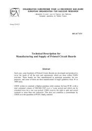
SI circuits suffice here. The block diagram of the controller is shown in Figure 3.<br />
Wa<br />
Wr<br />
Rr<br />
Ra<br />
Controller<br />
Pre<br />
Dn<br />
WL<br />
Dn<br />
WE<br />
Dn<br />
Data<br />
Memory<br />
Figure 3 Block diagram of the controller.<br />
There are two handshake protocols ((Wr,Wa) and (Rr,Ra)) to connect with the<br />
processing unit and three protocols ((Pre,Dn), (WL,Dn), and (WE,Dn)) with the<br />
memory system. The signals (Wr,Wa) are the writing request and its finish signals.<br />
The (Rr,Ra) pair is the reading request and its finish signals. The (Pre,Dn) handshake<br />
is the precharge request and its done signals.<br />
The STG specifications of the reading and writing operation are shown in Figure 4.