Extruded Rolscreen storm door installation - Pella.com
Extruded Rolscreen storm door installation - Pella.com
Extruded Rolscreen storm door installation - Pella.com

You also want an ePaper? Increase the reach of your titles
YUMPU automatically turns print PDFs into web optimized ePapers that Google loves.
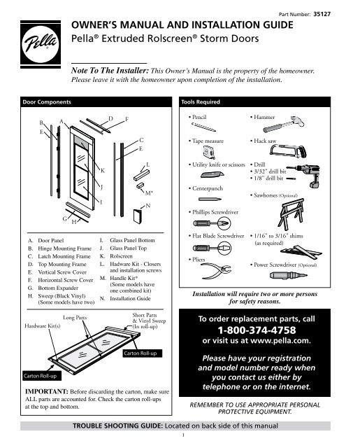
OWNER’S MANUAL AND INSTALLATION GUIDE<br />
<strong>Pella</strong> ® <strong>Extruded</strong> <strong>Rolscreen</strong> ® Storm Doors<br />
Part Number: 35127<br />
Note To The Installer: This Owner’s Manual is the property of the homeowner.<br />
Please leave it with the homeowner upon <strong>com</strong>pletion of the <strong>installation</strong>.<br />
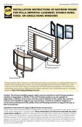
Door Components<br />
Tools Required<br />
B<br />
A<br />
D<br />
F<br />
• Pencil<br />
• Hammer<br />
E<br />
C<br />
E<br />
• Tape measure<br />
• Hack saw<br />
G H<br />
I<br />
K<br />
J<br />
L<br />
M*<br />
N<br />
• Utility knife or scissors<br />
• Centerpunch<br />
• Phillips Screwdriver<br />
• Drill<br />
• 3/32" drill bit<br />
• 1/8" drill bit<br />
• Sawhorses (Optional)<br />
A. Door Panel<br />
B. Hinge Mounting Frame<br />
C. Latch Mounting Frame<br />
D. Top Mounting Frame<br />
E. Vertical Screw Cover<br />
F. Horizontal Screw Cover<br />
G. Bottom Expander<br />
H. Sweep (Black Vinyl)<br />
(Some models have two)<br />
I. Glass Panel Bottom<br />
J. Glass Panel Top<br />
K. <strong>Rolscreen</strong><br />
L. Hadware Kit - Closers<br />
and <strong>installation</strong> screws<br />
M. Handle Kit*<br />
(Some models have<br />
one <strong>com</strong>bined kit)<br />
N. Installation Guide<br />
• Flat Blade Screwdriver<br />
• Pliers<br />
• 1/16" to 3/16" shims<br />
(as required)<br />
• Power Screwdriver (Optional)<br />
Installation will require two or more persons<br />
for safety reasons.<br />
Hardware Kit(s)<br />
Long Parts<br />
Short Parts<br />
& Vinyl Sweep<br />
(In roll-up)<br />
To order replacement parts, call<br />
1-800-374-4758<br />
or visit us at www.pella.<strong>com</strong>.<br />
Carton Roll-up<br />
Carton Roll-up<br />
IMPORTANT: Before discarding the carton, make sure<br />
ALL parts are accounted for. Check the carton roll-ups<br />
at the top and bottom.<br />
Please have your registration<br />
and model number ready when<br />
you contact us either by<br />
telephone or on the internet.<br />
REMEMBER TO USE APPROPRIATE PERSONAL<br />
PROTECTIVE EQUIPMENT.<br />
TROUBLE SHOOTING GUIDE: Located on back side of this manual<br />
1
BEFORE YOU BEGIN<br />
A. Remove the <strong>door</strong> from the carton.<br />
Note: Before discarding the carton, make sure ALL<br />
parts are accounted for. Check the carton roll-ups<br />
at the top and bottom.<br />
B. Record the <strong>door</strong>’s registration number<br />
for future reference.<br />
Note: The <strong>door</strong>’s registration label is<br />
located on the hinge mounting frame.<br />
Registration Number:<br />
Door Model Number:<br />
(see carton lablel)<br />
C. Determine which side you want your <strong>storm</strong><br />
<strong>door</strong> to hinge when viewed from the exterior<br />
of your home.<br />
Left Hinge<br />
Doors<br />
Right Hinge<br />
Doors<br />
Entry Door<br />
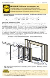
1 ENTRYWAY OPENING PREPARATION<br />
A. Verify the <strong>door</strong> will fit in the entryway opening. Measure the width of<br />
the opening in three locations. Using the smallest measurement, refer to<br />
the chart for shimming requirements and shim accordingly.<br />
1A<br />
Your entryway opening width (measured in inches)<br />
30” Storm Door less than 29-7/8” 29-7/8” to 30-1/16” Over 30-1/16” to 30-3/8” More than 30-3/8”<br />
32” Storm Door less than 31-7/8” 31-7/8” to 32-1/16” Over 32-1/16” to 32-3/8” More than 32-3/8”<br />
34” Storm Door less than 33-7/8” 33-7/8” to 34-1/16” Over 34-1/16” to 34-3/8” More than 34-3/8”<br />
36” Storm Door less than 35-7/8” 35-7/8” to 36-1/16” Over 36-1/16” to 36-3/8” More than 36-3/8”<br />
Shim<br />
Requirement<br />
Custom<br />
<strong>door</strong> size<br />
re<strong>com</strong>mended<br />
No shim<br />
required<br />
Add shims on the hinge side<br />
to get down to the “No shim<br />
required” width range<br />
Custom<br />
<strong>door</strong> size<br />
re<strong>com</strong>mended<br />
1B<br />
Shim<br />
B. If required, shim the entry <strong>door</strong> frame. Using four shim<br />
sections each about 8” to 12” long, position to align with the<br />
hinges on the <strong>storm</strong> <strong>door</strong>. DO NOT extend the shim beyond the<br />
face of the entryway.<br />
Hinge<br />
Shim<br />
Shim must not extend<br />
beyond entryway<br />
2
2 GLASS AND SCREEN<br />
A. The glass and screen should be left in place while installing the <strong>storm</strong> <strong>door</strong>. The shipping block(s) at<br />
the top of the sash should not be removed until the <strong>installation</strong> is <strong>com</strong>plete.<br />
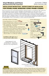
3 HINGE MOUNTING FRAME ASSEMBLY<br />
A. With the interior of the <strong>door</strong> facing up, position the hinge mounting frame on the <strong>door</strong> panel.<br />
Note: Notice the location of the weather-stripping.<br />
B. Align the pre-drilled hole with the outer hinge hole and<br />
install one hinge screw (#8 x 3/4" hex head).<br />
C. Check to ensure there is a 3/32" overhang from the highest point of the top of the <strong>door</strong>.<br />
Note: If the hinge side mounting frame extends more than or less than 3/32" above the top of the <strong>door</strong><br />
panel, remove the hinge screw. Position the hinge side mounting frame to achieve the 3/32" overhang,<br />
and centerpunch and drill a new 1/8" diameter hole through one of the other hinge holes. Install the<br />
(#8 x 3/4" hex head) hinge screw in the new hole.<br />
Top End<br />
3C<br />
Left Hinge Doors<br />
Right Hinge Doors<br />
3C<br />
Top End<br />
3/32" Overhang<br />
3/32" Overhang<br />
Inside<br />
facing<br />
up<br />
Pre-drilled<br />
Hole<br />
Score Line<br />
3D<br />
Outer<br />
Hole<br />
3A<br />
3A<br />
Score Line<br />
Outer<br />
Hole<br />
3D<br />
Pre-drilled<br />
Hole<br />
Inside<br />
facing<br />
up<br />
3B<br />
3B<br />
Weather<br />
stripping<br />
Hinge<br />
Screw<br />
Hinge<br />
Screw<br />
Weather<br />
stripping<br />
D. Align the hinge holes with the score line on the <strong>storm</strong> <strong>door</strong>.<br />
E. Centerpunch and drill the remaining hinge holes using a 1/8"<br />
drill bit and install the remaining hinge screws.<br />
F. Determine the finished length of the mounting frame.<br />
Measure the entryway height in two locations (see L1 and L2)<br />
on the side where the <strong>storm</strong> <strong>door</strong> hinges will be located and<br />
subtract 1/8" from both dimensions.<br />
Note: Measure the entryway with brickmould at the point<br />
where the brickmould attaches to the entry <strong>door</strong> frame.<br />
3<br />
3F<br />
L2<br />
L1
i<br />
I nterio r<br />
3 HINGE MOUNTING FRAME ASSEMBLY (CONTINUED)<br />
G. Turn the <strong>door</strong> over so the exterior faces up. Starting at the<br />
top of the hinge mounting frame and working toward the<br />
bottom, measure and mark the lengths L1 and L2 taken from<br />
the previous step.<br />
3G<br />
L1<br />
L2<br />
I nterio r<br />
E xterio r<br />
3H<br />
Straight<br />
Cut<br />
L1<br />
3G<br />
H. Matching the angle of your entryway sill, cut the bottom of<br />
the hinge mounting frame to length.<br />
Note: For a simplified <strong>installation</strong>, a straight cut a L1 may<br />
be made. For a more professional looking <strong>installation</strong>, an<br />
angled cut from L1 to L2 may be made.<br />
Angle<br />
Cut<br />
S il l<br />
Angle<br />
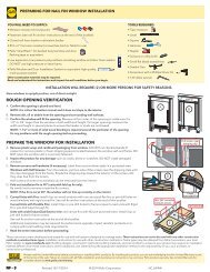
4 BOTTOM EXPANDER ASSEMBLY<br />
Interior<br />
Side<br />
S l<br />
d e<br />
Black<br />
Vinyl<br />
Sweep<br />
4A<br />
4B<br />
4C<br />
1/2”<br />
4D<br />
A. Slide the black vinyl sweep along the full length of the bottom expander.<br />
Note: Some models have two sweeps.<br />
B. Lock the sweep in place by pinching the ends of<br />
the inner legs.<br />
C. Cut the excess sweep from each end.<br />
D. For models with two sweeps, cut away a 1/2" wide notch<br />
from both ends of the interior sweep.<br />
E. Place the bottom expander onto the bottom of the <strong>door</strong><br />
with the sweep toward the interior. DO NOT install screws in<br />
the bottom expander at this time, adjustments are made in a<br />
later step.<br />
EXTERIOR<br />
4E<br />
Slide<br />
4
Two or more persons may be required for the following steps.<br />
5 INSTALL THE DOOR<br />
Note: The illustrations show the <strong>installation</strong> of a left hinge <strong>door</strong>.<br />
Right hinge <strong>door</strong>s are installed with the hinges to the right side<br />
of the entryway opening when viewed from the exterior.<br />
A. Set the <strong>door</strong> in the entryway opening resting the hinge<br />
side mounting frame on the sill. Slide the hinge tight<br />
against the entry <strong>door</strong> jamb or against any shims that were<br />
installed in Step 1B.<br />
B. Centerpunch and drill a 3/32" diameter hole through the<br />
top pre-drilled hole of the hinge mounting frame. Install a<br />
mounting frame screw (#6 x 1" Phillips pan head).<br />
Verify the <strong>door</strong> operates properly.<br />
5C<br />
Mounting<br />
Frame Screw<br />
5B<br />
Hinge Mounting Frame<br />
Slide<br />
Against<br />
Jamb<br />
Brickmould<br />
5A<br />
C. Centerpunch and drill a 3/32" diameter hole through the<br />
remaining pre-drilled holes of the hinge mounting frame.<br />
Install a mounting frame screw (#6 x 1" Phillips pan head).<br />
DO NOT overtighten.<br />
D. Open the <strong>door</strong>. Centerpunch and drill a 3/32” diameter<br />
hole through each pre-drilled hole of the hinge mounting<br />
frame. Install the inside jamb screws (#8 x 3/4" Phillips pan<br />
head). DO NOT overtighten.<br />
5D<br />
Inside Jamb<br />
Screw<br />
Top Mounting Frame<br />
6 TOP MOUNTING FRAME<br />
A. With the <strong>door</strong> open, position the top mounting frame so it<br />
rests on the hinge mounting frame.<br />
6C<br />
Mounting<br />
Frame Screw<br />
B. Close the <strong>door</strong> and align the end of the top mounting frame<br />
with the outer edge of the hinge mounting frame. Position to<br />
achieve a uniform gap between the top mounting frame and<br />
the <strong>door</strong>.<br />
C. Centerpunch and drill a 3/32" diameter hole through each<br />
pre-drilled hole of the top mounting frame. Secure the top<br />
mounting frame with the mounting frame screws (#6 x 1"<br />
Phillips pan head).<br />
Note: Drill and install the hinge<br />
side screw first.<br />
7A<br />
L3 L4<br />
Weather Stripping<br />
7 LATCH MOUNTING FRAME<br />
A. Measure the latch side height from the underside of<br />
the top mounting frame to the sill (see L3 and L4).<br />
Note: Measure entryway with brickmould at the<br />
point where the brickmould attaches to the entry<br />
<strong>door</strong> frame.<br />
B. Starting at the top of the latch mounting frame,<br />
mark off your measurement (see L3 and L4) and<br />
cut to length matching the angle of the sill.<br />
Note: Notice the position of the weather-stripping.<br />
Copy the cuts made in step 3H.<br />
5<br />
Right<br />
Hand<br />
Straight<br />
Cut<br />
Angle<br />
Cut<br />
S il l<br />
Angle<br />
L3<br />
L4<br />
7B<br />
Left<br />
Hand
7 LATCH MOUNTING FRAME (CONTINUED)<br />
C. Position the latch mounting frame in the entryway<br />
and align based on your model's <strong>door</strong> frame style.<br />
D. Position the latch mounting frame in the entryway<br />
opening. Line up th exterior end of the latch side mounting<br />
frame with the end of th etop mounting frame. Beginning at<br />
the top hole, centerpunch and drill a 3/32" diameter hole<br />
through the pre-drilled hole of the latch mounting frame. Be<br />
sure the <strong>door</strong> panel overlaps the mounting frame evenly from<br />
top to bottom. Install a mounting frame screw (#6 x 1" Phillips<br />
pan head) in each hole.<br />
C1<br />
0" to 5/16"<br />
Latch Side<br />
Mounting Frame<br />
Mounting Frame<br />
Weatherstrip<br />
Storm<br />
Door<br />
Hint: Drilling and installing the top screw first makes it easier<br />
to align the mounting frame correctly.<br />
8 BOTTOM EXPANDER ADJUSTMENT<br />
A. Close the <strong>door</strong> and adjust the bottom expander so it is centered on the <strong>door</strong> and the sweep lightly<br />
contacts the sill. Remove the protective plastic film from the bottom expander.<br />
B. From the interior, 4" in and 1/4" down,<br />
centerpunch and drill a 1/8" hole on both ends<br />
of the bottom expander. Drill through the<br />
bottom expander and interior surface of the <strong>door</strong>.<br />
C. Install a bottom expander screw (#6 x 1/2"<br />
Phillips pan head) in each end.<br />
8B<br />
Sill<br />
Slide<br />
4"<br />
1/4"<br />
Sweep<br />
Bottom<br />
Expander<br />
Screw<br />
8C<br />
Note: Use a hand screwdriver to secure the<br />
expander. DO NOT us a power screwdriver.<br />
8A<br />
6
9 DOOR HANDLE HARDWARE<br />
A. Handle Hardware: To install the handle assembly, refer to the<br />
separate instruction sheet included in the handle hardware box.<br />
9A<br />
10 DOOR CLOSERS<br />
A. On the hinge side of your entryway, position a jamb<br />
closer bracket even with the top of the bottom expander,<br />
(see the dotted line in the illustration) and 1/4" back from<br />
the mounting frame. Mark the screw hole locations and<br />
drill 1/8" diameter holes.<br />
B. Install the bottom jamb closer brackets using four jamb<br />
bracket screws (#10 x 1-1/2" Phillips pan head) for each bracket.<br />
Even<br />
10A<br />
w ith<br />
Top<br />
1/4"<br />
back<br />
Jamb<br />
Closer<br />
Bottom<br />
Expander<br />
Bracket<br />
C. Attach the bottom closer (with One-Touch ® button)<br />
rod to the jamb bracket using the short closer pin, then pull<br />
the <strong>door</strong> closer and slide the SHORT spacer clip onto the<br />
closer rod as shown. Rotate the closer so the One-touch ®<br />
button is along the top of the closer.<br />
Short Spacer Clip<br />
Short Closer Pin<br />
Long Closer<br />
Pin<br />
Door<br />
Closer<br />
Bracket<br />
Short Closer Pin<br />
Short Spacer Clip<br />
One-Touch ®<br />
Button<br />
Jamb Closer<br />
Bracket Screws<br />
STO<br />
RM<br />
D O O R<br />
D. Attach the <strong>door</strong> closer bracket to the <strong>door</strong> closer, by<br />
removing the O-ring and pin, then reinserting the pin.<br />
10D<br />
Door Closer<br />
Adjustment<br />
Screw<br />
10C<br />
Door Closer<br />
Rod<br />
10B<br />
Long Closer Pin<br />
Remove<br />
10D<br />
Discard<br />
Insert<br />
7
10 DOOR CLOSERS (CONTINUED)<br />
E. With the <strong>door</strong> tightly closed, align the bottom<br />
<strong>door</strong> closer bracket with the top of the bottom<br />
expander. Mark the centers of the hole pattern.<br />
Center punch and drill 1/8" diameter holes through<br />
the interior face of the <strong>door</strong>.<br />
F. Install the <strong>door</strong> closer bracket with two <strong>door</strong><br />
closer bracket screws (#10 x 5/8" Phillips pan head).<br />
10F<br />
Bottom<br />
Expander<br />
Door<br />
Closer<br />
Bracket<br />
Long Closer<br />
Pin<br />
10G<br />
Door Closer<br />
Bracket Screw<br />
10G<br />
Spacer Clip<br />
STORM DOOR<br />
Remove<br />
and<br />
Discard<br />
G. Discard spacer clip from the closer rod.<br />
2" Down<br />
1" Line<br />
H. Measure the distance from the hinge side of the entryway, to<br />
the end of the bottom <strong>door</strong> closer bracket. Mark this end distance<br />
on the label located near the top of the <strong>door</strong>.<br />
I. Position the bottom edge of the top <strong>door</strong> closer bracket<br />
on the dashed line of the label located near the top of the<br />
<strong>door</strong> panel.<br />
Door<br />
Closer<br />
Bracket<br />
10H<br />
10I<br />
Entry<br />
Door<br />
Jamb<br />
Hinge<br />
Side<br />
J. Position the end of the <strong>door</strong> closer bracket on the mark<br />
from step H. Mark the screw locations for the top <strong>door</strong><br />
closer bracket. Center punch and drill 1/8" diameter pilot<br />
holes. Remove the label.<br />
Line from<br />
10H<br />
1/8" Pilot<br />
Hole<br />
Door Closer<br />
Bracket<br />
1/8" Pilot<br />
Hole<br />
Dashed Line on the Label<br />
10J<br />
K. Install the top <strong>door</strong> closer bracket with two <strong>door</strong> closer<br />
bracket screws (#10 x 5/8" Phillips pan head).<br />
Door Closer<br />
Bracket<br />
10K<br />
Door Closer<br />
Bracket Screws<br />
8
STORM DOOR<br />
10 DOOR CLOSERS (CONTINUED)<br />
Remove<br />
10L<br />
L. Attach the <strong>door</strong> closer bracket to the <strong>door</strong> closer, by<br />
removing the O-ring and pin, then reinserting the pin.<br />
Discard<br />
Insert<br />
M. Attach the top closer rod to the jamb bracket<br />
using the short closer pin.<br />
Long Closer<br />
Pin<br />
Door<br />
Closer<br />
Bracket<br />
Short Closer Pin<br />
10M<br />
N. Holding the closer level, position the jamb closer<br />
bracket against the entryway jamb. Ensure the jamb<br />
closer bracket is 1/4" back from the hinge side mounting<br />
frame, mark the mounting screw locations and drill 1/8"<br />
diameter pilot holes.<br />
10L<br />
Door Closer<br />
Adjustment<br />
Screw<br />
Door Closer<br />
Rod<br />
O. Install the top jamb closer bracket using four jamb<br />
bracket screws (#10 x 1-1/2" Phillips pan hear) for<br />
each bracket.<br />
10O<br />
Jamb Closer<br />
Bracket Screws<br />
Note: Removing the <strong>door</strong> jamb bracket from the closer<br />
may make <strong>installation</strong> of the bracket easier.<br />
Jamb<br />
Closer<br />
Bracket<br />
10N<br />
1/4"<br />
back<br />
<br />
<br />
P. Open the <strong>door</strong> and check the closer speed. The speed of each<br />
closer may be adjusted by turning the adjustment screw. Turn the<br />
screw clockwise to reduce the closer speed or counter clockwise to<br />
increase the closer speed.<br />
Q. To use the One-Touch ® Button: Tap the button and open the<br />
<strong>door</strong>. To close, nudge the <strong>door</strong> open slightly.<br />
10P<br />
Adjustment<br />
Screw<br />
Faster-Slower<br />
9
11 EXTERIOR SCREW COVERS<br />
A. Screw Covers: Starting flush at one end, install the horizontal screw cover strip by inserting the angled<br />
edge into the outer most track and pressing in place. Repeat this procedure for the two vertical screw<br />
covers starting at the top of the mounting frames.<br />
Note: Cut the vertical screw covers to match the length of the mounting frame by<br />
scoring with a utility knife, then snapping in two.<br />
Horizontal<br />
Screw<br />
Cover<br />
Vertical<br />
Screw<br />
Cover<br />
11A<br />
12 GLASS AND ROLSCREEN ® OPERATION<br />
A. Remove the shipping block(s) located between the top<br />
of the sash and the <strong>Rolscreen</strong> ® cover.<br />
Note: The <strong>Rolscreen</strong> is attached to the<br />
top of the glass panel and will fill the<br />
ventilation area as the glass is lowered.<br />
B. Locking the glass panel - slide the<br />
exterior glass upward and the sash lock<br />
will automaticaly engage.<br />
Sash<br />
Handle<br />
Screen (Attached)<br />
12B<br />
Sash Lock<br />
C. Unlocking the glass panel - press the<br />
sash lock button inward as shown and<br />
lower the glass panel. Slide the upper<br />
glass panel to any position for<br />
ventilation preference.<br />
Note: The <strong>Rolscreen</strong> will automatically<br />
retract as the glass slides upward.<br />
P ush<br />
T o Unlock<br />
S ash<br />
12C<br />
10
CARE AND MAINTENANCE<br />
Door<br />
Cleaning<br />
Routine Cleaning: Painted metal surfaces of the <strong>door</strong> may be cleaned by using a soft cloth with<br />
a mild soap and water solution, or any househole grease-cutting cleaner.<br />
Note: Light marks on the painted surfaces of the <strong>door</strong> can be removd using turpentine or any<br />
household grease-cutting cleaner.<br />
Bottom<br />
Expander<br />
Cleaning<br />
IMPORTANT: DO NOT use brass polish or steel wool on the bottom expander.<br />
The bottom expander is an aluminum product with a simulated metallic anodized finish.<br />
Use a soft cloth with mild soap and water solution or any household grease-cutting cleaner.<br />
Plain<br />
Glass<br />
Cleaning<br />
Brass &<br />
Other<br />
Metallic<br />
Handle<br />
Cleaning<br />
Models with decorative glass - follow instructions below.<br />
Note: DO NOT use an ammonia-based cleaner for the first cleaning of the glass.<br />
First Cleaning: Use a mixture of one part vinegar with four parts water to remove the<br />
protective coating (applied for shipping protection) from the glass.<br />
Routine Cleaning: Use a soft cloth with mild soap and water solution, or any<br />
household glass cleaner.<br />
Routine Cleaning: Use a soft cloth with a mild soap and water solution to clean the surfaces.<br />
Apply a high quality, non-abrasive automobile wax to polish.<br />
Note: DO NOT use ammonia-based cleaners on brass or other metallic finish handles.<br />
Cleaning &<br />
Refinishing<br />
Damaged<br />
Brass<br />
If your <strong>Pella</strong> ® <strong>door</strong> includes a Bright Brass solid brass handle, the brass is polished and sealed with a clear coating by the<br />
manufacturer. (Oil-Rubbed Bronze is living finish that will develop it's own unique patina with use.) Should the finish be<br />
accidentally damaged by an abrasive or sharp object, it will succumb to a natural oxidation process that occurs when the<br />
elements contact unprotected brass. Brass has an enduring quality, in that it can be refurbished to its original polished finish<br />
again and again by using a quality brass polish<br />
such as Brasso ® and a soft cloth.<br />
1. Remove the hardware from the <strong>door</strong> so the finish of the <strong>door</strong> will not be affected. See the hardware instructions for removal.<br />
Note: You may be able to leave the hardware in place on the <strong>door</strong> when polishing the handle. Make certain to <strong>com</strong>pletely<br />
mask off all areas around the handle before starting. If polishing the key cylinder, protect the internal mechanism by<br />
covering the opening with tape.<br />
2. Use a quality brass polish or cleaner to clean the brass - follow the product’s manufacturer's directions.<br />
Note: Firm rubbing may be necessary to loosen the coating on the brass.<br />
3. Reseal the brass per instructions below.<br />
a. Apply a high quality, non-abrasive, polymer-based automobile wax - follow the product manufacturer's directions.<br />
b. Apply a clear coat lacquer spray to the brass - follow the product’s manufacturer's directions.<br />
Note: If you removed the hardware from the <strong>door</strong>, lubricate any internal workings with a spray lubricant.<br />
Re-install the hardware on the <strong>door</strong> using the hardware <strong>installation</strong> instructions.<br />
11
TROUBLE SHOOTING GUIDE<br />
If you have a question that you do not see listed here, or have not been able to resolve through your <strong>Pella</strong> ® Owner’s<br />
Manual and Installation Guide, call one of our customer service representatives toll-free at 1-800-374-4758.<br />
Common Questions Probable Causes Suggested Solutions<br />
Door does not open or<br />
close properly<br />
Handle does not latch<br />
properly.<br />
Glass/Screen does not<br />
operate properly<br />
Water between the <strong>storm</strong><br />
<strong>door</strong> and entry <strong>door</strong><br />
Entryway opening is out of square/plumb<br />
or frame is warped<br />
Closer out of position<br />
• Verify the opening and shim to square as necessary.<br />
• Remove the adjustment screw from the closer and cycle the <strong>door</strong> a few times, replace the screw and adjust for<br />
proper speed. Disconnect the other closer from <strong>door</strong>, to adjust one closer at a time.<br />
• Verify the arrow on the jamb bracket is pointing toward the <strong>storm</strong> <strong>door</strong>. If not, reverse the bracket.<br />
• Adjust the position of the closer <strong>door</strong> bracket until the <strong>door</strong> closes properly.<br />
Closer pin in the screen use position • Move the closer pin to the glass use position. (See steps 10D and 10L)<br />
Bottom expander out of position<br />
Top mounting frame out of alignment<br />
Hinges binding<br />
Latch not hitting strike plate<br />
Lockbody upside down (mortise<br />
hardware)<br />
Closer is out of position<br />
Screen out of alignment<br />
Screen does not retract when raising<br />
the glass panel<br />
Weep holes clogged<br />
Bottom Sweep is making a tight seal<br />
against the <strong>door</strong> sill<br />
• Verify the expander is centered on the <strong>door</strong> - adjust as necessary.<br />
• Verify the expander is not too low - raise the expander up so the sweep just contacts the sill.<br />
• Verify the top mounting frame weather stripping is positioned between the latch and hinge mounting frames<br />
and not overlapping.<br />
• Verify mounting frame screws are not overtightened - back off screws slightly.<br />
• Verify entryway framing is not twisted or warped - shim or modify as necessary.<br />
• Verify hinge mounting frame is not twisted or bent - replace if necessary.<br />
• Adjust the strike plate so the latch catches properly - add shims as necessary.<br />
• Verify the live bolt is above the deadbolt and the live bolt is positioned correctly - see hardware <strong>installation</strong><br />
sheet for proper placement.<br />
• See “Closer out of position” in the “Door does not open / close properly” question above.<br />
• Lower the glass panel and manually reinsert the screen onto the track at the top of the <strong>door</strong>. Fully raise and<br />
lower the glass panel.<br />
• With the <strong>door</strong> in an open position, grasp the middle of the screen area by reaching one arm around each side<br />
of the <strong>door</strong> and pressing your hands together. Pull screen down firmly two or three inches, then release the<br />
screen, (similar to releasing a window shade). The sceen should now retract properly. If this procedure does<br />
not work, the screen may need to be replaced.<br />
• Check the bottom window insert track and exterior drainage holes for obstructions.<br />
• Open the <strong>storm</strong> <strong>door</strong> and notch up to 1/2” off both the latch and hinge end of the vinyl sweep.<br />
Note: DO NOT cut down the <strong>door</strong> panel. Cutting down the <strong>door</strong> panel will void the warranty.<br />
PELLA ® STORM DOORS LIMITED WARRANTY - Effective July 2006<br />
Congratulations on choosing a <strong>Pella</strong> ® <strong>storm</strong> <strong>door</strong> to protect and beautify your home. This superior quality <strong>door</strong> has been designed to give you years of<br />
trouble-free service, and you are protected by this limited warranty:<br />
<strong>Pella</strong> ® warrants to the ORIGINAL HOMEOWNER PURCHASER of this <strong>storm</strong> <strong>door</strong> that it will, without charge to the purchaser, provide parts or<br />
exchange, at its option, any <strong>door</strong> determined to be defective in material or workmanship for 20 years after the purchase date. The purchaser will be<br />
responsible for transportation charges. Should the <strong>door</strong> be determined to be defective in material or workmanship AFTER 20 years from the purchase<br />
date, the original purchaser may buy one new <strong>Pella</strong> <strong>storm</strong> <strong>door</strong> at 50% of the then-current manufacturer’s suggested list price for as long as the original<br />
purchaser owns the home on which the <strong>door</strong> was installed. The purchase must be made directly from the factory, and all transportation charges are the<br />
responsibility of the purchaser.<br />
Should the <strong>door</strong> be determined to be defective and the purchaser incurs a re<strong>installation</strong> cost within three years of the purchase date, he or she may be<br />
reimbursed for these costs up to a maximum of $25.00, upon furnishing a copy of the invoice for the re<strong>installation</strong> costs.<br />
As a condition of this warranty, it is required that the <strong>door</strong> be used for residential use only in an owner-occupied home, that it be installed properly as an<br />
operating <strong>door</strong> according to manufacturer’s instructions, and that it not be altered in any way. For multi-unit housing applications, ask your dealer for a<br />
copy of the appropriate warranty or phone <strong>Pella</strong>’s Customer Service Department at the phone number listed below. This warranty is not transferable.<br />
To make a claim under this warranty, you must:<br />
a) Call our Customer Service Department at 1-888-646-5354 or write to <strong>Pella</strong> Warranty Service, 2333 Eastbrook Drive, Brookings, SD 57006 USA.<br />
b) Furnish the original or a copy of the sales receipt or other documents showing the original purchase date and that you are the original purchaser<br />
of this <strong>door</strong>. Exchange is limited to supplying a replacement <strong>door</strong> of <strong>com</strong>parable size, style, and color and does not include any cost of removal<br />
or <strong>installation</strong> except as noted above.<br />
The warranty on the latch set and air closer is one year, and any labor charges are not covered. This warranty excludes all damage to glass and screen.<br />
This warranty does not cover problems caused by improper storage, handling, <strong>installation</strong>, use, modification, or maintenance, by Acts of God or by accidents,<br />
including accidental glass breakage. It does not apply to normal wear or discoloration of finish; finish problems caused by mechanical damage<br />
or abrasion; normal effects of sun and weather, including acid rain, salt spray, or other corrosive elements; damage caused by severe wind; or damage<br />
caused by customer abuse or neglect. Oil-Rubbed Bronze is a living finish that will develop its own unique patina with use and is not covered under<br />
the Lifetime Finish Guarantee. Bright Brass, Antique Brass, Brushed Brass and Satin Nickel hardware is guaranteed not to tarnish and carries a lifetime<br />
finish warranty for as long as the purchaser owns their home.<br />
THIS WARRANTY EXCLUDES ALL INCIDENTAL AND CONSEQUENTIAL DAMAGES. Nothing in this document shall give rise to or extend<br />
the period of any warranties implied under state or provincial law, and no implied warranty shall extend beyond the periods covered by this written warranty.<br />
Neither <strong>Pella</strong> Corporation nor any seller of <strong>Pella</strong> ® products will be responsible for incidental or consequential damages which may result from a<br />
product defect or malfunction. Some states do not allow the exclusion or limitation of incidental or consequential damages, so the above limitation or<br />
exclusion may not apply to you. This warranty gives you specific legal rights, and you may have additional rights which vary from state to state.<br />
UPDATED JULY 2006<br />
© 2007<br />
12