Bravo Transom Assembly Specifications
Bravo Transom Assembly Specifications
Bravo Transom Assembly Specifications

You also want an ePaper? Increase the reach of your titles
YUMPU automatically turns print PDFs into web optimized ePapers that Google loves.
SERVICE MANUAL NUMBER 11<br />
SERVICE PROCEDURES REQUIRING MINOR DISASSEMBLY<br />
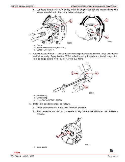
b. Lubricate sleeve O.D. with soapy water or engine cleaner and install sleeve with<br />
sleeve installation tool and a suitable driving rod.<br />
a<br />
b<br />
a - Sleeve<br />
b - Sleeve Installation Tool (91-818162)<br />
c - Suitable Driving Rod<br />
73906<br />
c<br />
50327<br />
4. Apply Locquic Primer “T” to internal bell housing threads and external hinge pin threads<br />
and allow to dry. Apply Loctite 27131 to bell housing threads and install hinge pins.<br />
Torque hinge pins to 140-150 lb. ft. (189-203 N·m).<br />
a<br />
c<br />
b<br />
a - Bell Housing<br />
b - Gimbal Ring<br />
c - Hinge Pin Tool (P/N 91-78310)<br />
23292<br />
5. Install trim position sender as follows:<br />
a. Place sterndrive unit in the full DOWN/IN position.<br />
b. Turn center rotor of trim position sender to align index mark with index mark on sender<br />
body.<br />
a<br />
a - Index Marks<br />
71218<br />
90-17431--4 MARCH 1998 Page 4A-13