Bravo Transom Assembly Specifications
Bravo Transom Assembly Specifications
Bravo Transom Assembly Specifications

You also want an ePaper? Increase the reach of your titles
YUMPU automatically turns print PDFs into web optimized ePapers that Google loves.
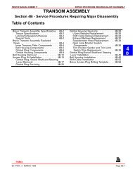
SERVICE PROCEDURES REQUIRING MINOR DISASSEMBLY SERVICE MANUAL NUMBER 11<br />
<strong>Bravo</strong> <strong>Transom</strong> <strong>Assembly</strong> <strong>Specifications</strong><br />
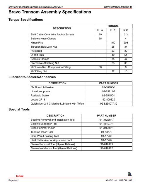
Torque <strong>Specifications</strong><br />
TORQUE<br />
DESCRIPTION<br />
lb. in. lb. ft. N·m<br />
Shift Cable Core Wire Anchor Screws 20 2.3<br />
Bellows Hose Clamps 35 4<br />
Hinge Pins 150 203<br />
Through Bolt Lock Nut 25 34<br />
Pivot Bolt 23 30<br />
U-bolt Nuts 40 54<br />
Bellows Clamps 35 47<br />
Sterndrive Attaching Nut 23 30<br />
90° Hose-Barb Compression Fitting 80 9<br />
90° Fitting Nut 12 16<br />
Lubricants/Sealers/Adhesives<br />
Special Tools<br />
DESCRIPTION<br />
PART NUMBER<br />
3M Brand Adhesive 92-86166-1<br />
Liquid Neoprene 92-25711-2<br />
Resiweld Sealer 92-65150-1<br />
Loctite 27131 92-809820<br />
Quicksilver 2-4-C Marine Lubricant with Teflon 92-825407A12<br />
DESCRIPTION<br />
PART NUMBER<br />
Bearing Removal and Installation Tool 91-31229A7<br />
Bellows Expander Tool 91-45497A1<br />
Slide Hammer Puller 91-34569A1<br />
Tapered Insert Tool 91-43579<br />
Core Wire Locating Tool 91-17263<br />
Shift Cable Anchor Adjustment Tool 91-17262<br />
Sleeve Removal Tool (U-joint Bellows) 91-818169<br />
Sleeve Installation Tool (U-joint Bellows) 91-818162<br />
Page 4A-2 90-17431--4 MARCH 1998