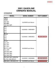
Bravo Transom Assembly Specifications
Bravo Transom Assembly Specifications
Bravo Transom Assembly Specifications

Create successful ePaper yourself
Turn your PDF publications into a flip-book with our unique Google optimized e-Paper software.
SERVICE MANUAL NUMBER 11<br />
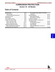
Cleaning and Inspection<br />
Installation<br />
SERVICE PROCEDURES REQUIRING MINOR DISASSEMBLY<br />
1. Inspect exhaust bellows for internal charring, cracks, cuts or hardening.<br />
2. Clean old adhesive from bellows mounting flange on gimbal housing and on bell housing<br />
with lacquer thinner.<br />
3. Clean old adhesive from mounting surface of exhaust bellows if using old bellows.<br />
4. Roughen exhaust bellows mating surfaces with sandpaper and wipe clean with lacquer<br />
thinner.<br />
WARNING<br />
Be sure to follow label directions when using bellows adhesive.<br />
1. Apply bellows adhesive to mounting surfaces on inside of bellows. Allow adhesive to dry<br />
until no longer tacky, (approximately 10 min.).<br />
CAUTION<br />
Bellows clamps may corrode if grounding clips are not installed.<br />
2. Position grounding clips on bellows.<br />
b<br />
a<br />
a<br />
c<br />
22079<br />
a - Apply Bellows Adhesive<br />
b - Grounding Clips<br />
c - Part Number - all replacement bellows should be P/N 18654. Do not use earlier model bellows.<br />
3. Install exhaust bellows on gimbal housing. Torque to 35 lb. in. (4 N·m).<br />
b<br />
a<br />
a - Exhaust Bellows<br />
b - Hose Clamp<br />
75964<br />
90-17431--4 MARCH 1998 Page 4A-29