Technical Specifications for the Rehabilitation of ... - DN Higgins, Inc.
Technical Specifications for the Rehabilitation of ... - DN Higgins, Inc.
Technical Specifications for the Rehabilitation of ... - DN Higgins, Inc.

You also want an ePaper? Increase the reach of your titles
YUMPU automatically turns print PDFs into web optimized ePapers that Google loves.
<strong>Technical</strong> <strong>Specifications</strong> <strong>for</strong> <strong>the</strong><br />
<strong>Rehabilitation</strong> <strong>of</strong> Pump Station 302.56<br />
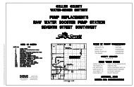
Collier County, Florida<br />
For Collier County Public Utilities Planning and Project Management Department<br />
County Project # 70046 May 2013<br />
Table <strong>of</strong> Contents:<br />
General Requirements<br />
01110 – Summary <strong>of</strong> Work<br />
01120 – Sequence <strong>of</strong> Work<br />
Collier County Public Utilities – Utilities Standards Manual<br />
<strong>Technical</strong> <strong>Specifications</strong><br />
Collier County Public Utilities – Approved Product List<br />
Special Construction<br />
099723 Concrete Coatings<br />
11312 Collections System Bypass<br />
Division 16 - Electrical
SECTION 01110<br />
SUMMARY OF WORK<br />
PART 1 -GENERAL<br />
1.01 SECTION INCLUDES<br />
General description <strong>of</strong> <strong>the</strong> Work required under this Contract.<br />
1.02 WORK COVERED BY CONTRACT DOCUMENTS<br />
A. Work <strong>of</strong> this Contract comprises construction at <strong>the</strong> Collier County Pump Station 302.56. The<br />
Contractor shall refer to <strong>the</strong> Contract Documents <strong>for</strong> a more complete description <strong>of</strong> <strong>the</strong> Work.<br />
B. The Work can be summarized to include furnishing labor, materials, equipment, services,<br />
incidentals <strong>for</strong> <strong>the</strong> following items:<br />
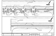
1. <strong>Rehabilitation</strong> <strong>of</strong> Pump Station 302.56 and associated improvements:<br />
a. Construction <strong>of</strong> a temporary wastewater bypass pumping system to accommodate <strong>the</strong><br />
inflows while <strong>the</strong> station is <strong>of</strong>fline <strong>for</strong> improvements. The system shall be online and in<br />
operation until completion <strong>of</strong> required functional start up and testing <strong>of</strong> new electrical<br />
components.<br />
b. Utilities improvements including demolition <strong>of</strong> existing wetwell components, valve vault,<br />
and electrical systems, patching, cleaning and <strong>the</strong> application <strong>of</strong> Sewpercoat to <strong>the</strong> wetwell<br />
where necessary based on <strong>the</strong> condition <strong>of</strong> <strong>the</strong> existing coating as determined during<br />
construction. New above- and below ground piping, valves and fittings <strong>for</strong> <strong>the</strong> <strong>for</strong>ce main.<br />
c. Comprehensive electrical systems improvements - switching, control panels, lightning<br />
grounding, and surge protection. <strong>Inc</strong>luding start up and functional testing.<br />
d. Miscellaneous site work including excavation, backfill, pavement and sod restoration.<br />
e. Miscellaneous work including painting, coatings, lightning protection, and all o<strong>the</strong>r work and<br />
responsibilities described in <strong>the</strong> Contract Documents.<br />
f. Temporary equipment and materials and manufacturers' trained field technicians <strong>for</strong> start-up,<br />
calibration, testing, and certification <strong>of</strong> installed equipment and systems.<br />
g. Provide Installation,Operation and Maintenance Manuals.<br />
1.03 PROJECT MILESTONE AND SCHEDULE<br />
The Contract work includes a project completion milestone with liquidated damages. Refer to<br />
Section 01120 and <strong>the</strong> Contract Documents <strong>for</strong> additional in<strong>for</strong>mation and requirements.<br />
1.04 CONTRACT ALLOWANCES AND CONSTRUCTION SCHEDULE<br />
A. The Contractor shall plan, coordinate and complete all work associated with <strong>the</strong> project within <strong>the</strong><br />
Contract Time.
1.05 SPECIAL EXPERIENCE REQUIREMENTS<br />
A. The Owner requires certain experience qualifications. The Contractor and <strong>the</strong> proposed project<br />
key personnel must have prior experience on similar projects. Refer to <strong>the</strong> Bid Proposal <strong>for</strong><br />
additional in<strong>for</strong>mation and requirements. Failure <strong>of</strong> a bidder to document such qualifications may<br />
result in rejection <strong>of</strong> that bid.<br />
1.06 CONTRACT METHOD<br />
Construct <strong>the</strong> Work under a single contract. Certain materials as described in <strong>the</strong> Contract<br />
Documents will be furnished by <strong>the</strong> Owner <strong>for</strong> unloading, storing, installation, start-up and testing<br />
assistance by <strong>the</strong> Contractor. The Contractor shall provide coordination and technical support<br />
associated with Owner furnished material.<br />
1.07 WORK BY OTHERS<br />
During <strong>the</strong> construction period <strong>for</strong> this project, <strong>the</strong> Owner (ei<strong>the</strong>r with his own <strong>for</strong>ces or<br />
under a separate contract) will be per<strong>for</strong>ming o<strong>the</strong>r work that will require <strong>the</strong><br />
cooperation <strong>of</strong> <strong>the</strong> Contractor in scheduling and his coordination to avoid conflicts.<br />
END OF SECTION
SECTION 01120<br />
SEQUENCE OF WORK<br />
PART 1 -GENERAL<br />
1.01 SECTION INCLUDES<br />
A special partial project completion milestone and schedule. and constraints regarding<br />
construction sequence.<br />
1.02 PROJECT MILESTONE SCHEDULE<br />
The Contractor shall plan, coordinate and prosecute <strong>the</strong> Contract Work so as to achieve<br />
Substantial Completion within 120 days from <strong>the</strong> Notice to Proceed Date. Final Completion<br />
shall be achieved by 180 days after <strong>the</strong> Notice to Proceed Date. Liquidated Damages will be<br />
assessed if <strong>the</strong> Contract Work has not achieved Final Completion by 180 days after <strong>the</strong> Notice<br />
to Proceed Date.<br />
The construction schedule shall identify <strong>the</strong> activities, logic, resources and completion dates<br />
necessary to meet <strong>the</strong> above completion dates.<br />
1.03 CONSTRUCTION SEQUENCING<br />
A The construction constraints and work sequences are not intended to be a complete or<br />
exhaustive list and <strong>the</strong> descriptions provided are general in nature. The Contractor is<br />
responsible <strong>for</strong> identifying and per<strong>for</strong>ming all work activities associated with <strong>the</strong> project. The<br />
following work sequences are intended to be general in nature and not inclusive <strong>of</strong> all steps or<br />
details.<br />
B The following areas <strong>of</strong> Contract Work require specific planning and coordination to avoid<br />
interruptions <strong>of</strong> sanitary sewer service to <strong>the</strong> affected customers.<br />
1 Construction <strong>of</strong> <strong>the</strong> temporary wastewater bypass pumping system to connect<br />
<strong>the</strong> necessary temporary bypass fittings. See <strong>the</strong> Collections System Bypass<br />
requirements located elsewhere in <strong>the</strong> specifications.<br />
2 Construction <strong>of</strong> <strong>the</strong> remaining improvements.<br />
3. Electrical systems functional start up and testing.<br />
4. Upon satisfactory per<strong>for</strong>mance <strong>of</strong> <strong>the</strong> station components, <strong>the</strong> station shall be<br />
placed in service prior to dismantling <strong>the</strong> temporary bypass pumping system.<br />
1.04 PLACEMENT OF CONSTRUCTION CRANES AND LIFTING EQUIPMENT<br />
A. As may required by applicable regulations and standards, <strong>the</strong> Contractor shall<br />
provide a detailed submittal <strong>for</strong> each placement <strong>of</strong> a construction crane or<br />
o<strong>the</strong>r lifting equipment. The submittal shall reflect compliance with all safety<br />
codes and standards and shall be site specific <strong>for</strong> each placement.<br />
PART 2 -PRODUCTS (not used)
PART 3 -EXECUTION (not used)<br />
END OF SECTION
SECTION 2<br />
TECHNICAL SPECIFICATIONS<br />
Go to <strong>the</strong> Collier County website below <strong>for</strong> <strong>the</strong> latest revision<br />
<strong>of</strong> <strong>the</strong> <strong>Technical</strong> <strong>Specifications</strong>:<br />
http://www.colliergov.net/
COLLIER COUNTY WATER-SEWER DISTRICT<br />
UTILITIES STANDARDS MANUAL<br />
SECTION 2<br />
TECHNICAL SPECIFICATIONS<br />
Table <strong>of</strong> Contents<br />
DIVISION 1 - GENERAL REQUIREMENTS<br />
011000 Summary <strong>of</strong> Work<br />
012000 Measurement and Payment<br />
014127 NPDES Requirements <strong>for</strong> Construction Activities Impacting More Than One<br />
Acre<br />
014200 References<br />
014500 Quality Control<br />
015000 Construction Facilities and Temporary Controls<br />
015526 Traffic Regulation and Public Safety<br />
015713 Temporary Erosion and Sedimentation Control <strong>for</strong> Construction Activities<br />
Impacting Less Than One Acre, including Construction Requiring<br />
Dewatering<br />
016100 Material and Equipment<br />
017300 Miscellaneous Work and Cleanup<br />
017416 Site Clearing<br />
017423 Cleaning<br />
017823 Operation and Maintenance Manuals<br />
017839 Project Record Documents<br />
DIVISION 2 - EXISTING CONDITIONS<br />
020500 Connections to Existing Systems<br />
022100 Lines and Grades<br />
022200 Pre-Construction Audio-Video Recording<br />
022501 Leakage Tests<br />
024100 Demolition<br />
025400 Disinfection<br />
DIVISION 3 - CONCRETE<br />
031100 Concrete Formwork<br />
032000 Concrete Rein<strong>for</strong>cement<br />
033100 Concrete, Masonry Mortar and Grout<br />
034100 Precast Concrete Structures<br />
SECTION 2<br />
COLLIER COUNTY<br />
TABLE OF CONTENTS<br />
TECHNICAL SPECIFICATIONS Page 1 <strong>of</strong> 2
DIVISION 5 – METALS<br />
055600 Metal Castings<br />
DIVISION 9 - FINISHES<br />
099723 Concrete Coatings<br />
DIVISION 31 - EARTHWORK<br />
312316 Excavation – Earth and Rock<br />
312319 Groundwater Control <strong>for</strong> Open Cut Excavation<br />
312323 Backfilling<br />
314000 Shoring, Sheeting and Bracing<br />
DIVISION 32 - EXTERIOR IMPROVEMENT<br />
320117 Pavement Repair and Restoration<br />
321300 Sidewalks, Driveways and Curbs<br />
323113 Chain Link Fencing and Gate<br />
329200 Restoration by Sodding or Seeding<br />
DIVISION 33 - UTILITIES<br />
330130.16 Televising and Inspection <strong>of</strong> Gravity Sewer Systems<br />
330201 Roadway Crossings by Open Cut<br />
330502 High Density Polyethylene (HDPE) Pipe and Fittings<br />
330503 Polyvinyl Chloride (PVC) Pipe and Fittings<br />
330504 Ductile Iron Pipe (DIP) and Fittings<br />
330518 Laying and Jointing Buried Pipelines<br />
330520 Pipe Removal and Abandonment<br />
330523.13 Horizontal Directional Drilling<br />
330523.16 Jacking, Augering and Mining<br />
331200 Water Valves and Appurtenances<br />
331619 Hydrants<br />
333200 Pumping Stations<br />
333313 Wastewater Valves and Appurtenances<br />
333913 Sewer Manholes<br />
334713 Irrigation Pond Liner<br />
SECTION 2<br />
COLLIER COUNTY<br />
TABLE OF CONTENTS<br />
TECHNICAL SPECIFICATIONS Page 2 <strong>of</strong> 2
SECTION 011000<br />
SUMMARY OF WORK<br />
PART 1 GENERAL<br />
1.1 SECTION INCLUDES<br />
A. Description <strong>of</strong> Work<br />
B. CONTRACTOR's Use <strong>of</strong> Site<br />
C. Work Sequence<br />
D. COUNTY Occupancy<br />
1.2 DESCRIPTION OF WORK<br />
A. General: The Work to be done under this Contract is shown on <strong>the</strong> drawings and<br />
specified in Contract Documents.<br />
B. The Work includes:<br />
1. Furnishing <strong>of</strong> all labor, material, superintendence, plant, power, light, heat,<br />
fuel, water, tools, appliances, equipment, supplies, services and o<strong>the</strong>r<br />
means <strong>of</strong> construction necessary or proper <strong>for</strong> per<strong>for</strong>ming and completing<br />
<strong>the</strong> Work.<br />
2. Sole responsibility <strong>for</strong> adequacy <strong>of</strong> plant and equipment.<br />
3. Maintaining <strong>the</strong> Work area and site in a clean and acceptable manner.<br />
4. Maintaining existing facilities in service at all times.<br />
5. Protection <strong>of</strong> finished and unfinished Work.<br />
6. Repair and restoration <strong>of</strong> Work or existing facilities damaged during<br />
construction.<br />
7. Furnishing as necessary proper equipment and machinery, <strong>of</strong> a sufficient<br />
capacity, to facilitate <strong>the</strong> Work and to handle all emergencies normally<br />
encountered in Work <strong>of</strong> this character.<br />
Section 011000<br />
COLLIER COUNTY<br />
SUMMARY OF WORK<br />
TECHNICAL SPECIFICATIONS Page 1 <strong>of</strong> 4
8. Furnishing, installing, and protecting all necessary guides, track rails,<br />
bearing plates, anchor and attachment bolts, and all o<strong>the</strong>r appurtenances<br />
needed <strong>for</strong> <strong>the</strong> installation <strong>of</strong> <strong>the</strong> devices included in <strong>the</strong> equipment<br />
specified. Make anchor bolts <strong>of</strong> appropriate size, strength and material <strong>for</strong><br />
<strong>the</strong> purpose intended. Furnish substantial templates and shop drawings <strong>for</strong><br />
installation.<br />
C. Implied and Normally Required Work: It is <strong>the</strong> intent <strong>of</strong> <strong>the</strong>se <strong>Specifications</strong> to<br />
provide <strong>the</strong> COUNTY with complete operable systems, subsystems and o<strong>the</strong>r<br />
items <strong>of</strong> Work. Any part or item <strong>of</strong> Work, which is reasonably implied or normally<br />
required to make each installation satisfactorily and completely operable, is<br />
deemed to be included in <strong>the</strong> Work and <strong>the</strong> Contract Amount. All miscellaneous<br />
appurtenances and o<strong>the</strong>r items <strong>of</strong> Work incidental to meeting <strong>the</strong> intent <strong>of</strong> <strong>the</strong>se<br />
<strong>Specifications</strong> are included in <strong>the</strong> Work and <strong>the</strong> Contract Amount even though<br />
<strong>the</strong>se appurtenances may not be specifically called <strong>for</strong> in <strong>the</strong>se <strong>Specifications</strong>.<br />
D. Quality <strong>of</strong> Work: Regard <strong>the</strong> apparent silence <strong>of</strong> <strong>the</strong> Contract Documents as to<br />
any detail, or <strong>the</strong> apparent omission from <strong>the</strong>m <strong>of</strong> a detailed description<br />
concerning any Work to be done and materials to be furnished as meaning that<br />
only <strong>the</strong> best general practice is to prevail and that only materials and<br />
workmanship <strong>of</strong> <strong>the</strong> best quality are to be used. Interpretation <strong>of</strong> <strong>the</strong>se<br />
specifications will be made upon this basis.<br />
1.3 CONTRACTOR'S USE OF SITE<br />
A. In addition to <strong>the</strong> requirements <strong>of</strong> <strong>the</strong> Supplemental Terms and Conditions, limit<br />
use <strong>of</strong> site and premises <strong>for</strong> work and storage to allow <strong>for</strong> <strong>the</strong> following:<br />
1. Coordination <strong>of</strong> <strong>the</strong> Work under this CONTRACT with <strong>the</strong> work <strong>of</strong> <strong>the</strong> o<strong>the</strong>r<br />
contractors where Work under this CONTRACT encroaches on <strong>the</strong> Work <strong>of</strong><br />
o<strong>the</strong>r contractors.<br />
2. COUNTY occupancy and access to operate existing facilities.<br />
3. Coordination <strong>of</strong> site use with ENGINEER.<br />
4. Responsibility <strong>for</strong> protection and safekeeping <strong>of</strong> products under this<br />
CONTRACT.<br />
5. Providing additional <strong>of</strong>f site storage at no additional cost to <strong>the</strong> COUNTY as<br />
needed.<br />
1.4 WORK SEQUENCE<br />
A. Construct Work in stages to accommodate <strong>the</strong> COUNTY’s use <strong>of</strong> premises during<br />
construction period and in accordance with <strong>the</strong> limitations on <strong>the</strong> sequence <strong>of</strong><br />
construction specified. Coordinate construction schedules and operations with<br />
ENGINEER.<br />
Section 011000<br />
COLLIER COUNTY<br />
SUMMARY OF WORK<br />
TECHNICAL SPECIFICATIONS Page 2 <strong>of</strong> 4
B. Coordinate Work <strong>of</strong> all subcontractors.<br />
1.5 COUNTY OCCUPANCY<br />
A. The COUNTY will occupy premises during entire period <strong>of</strong> construction in order to<br />
maintain normal operations. Cooperate with <strong>the</strong> COUNTY's Manager or designee<br />
in all construction operations to minimize conflict, and to facilitate COUNTY usage.<br />
B. Conduct operations with <strong>the</strong> least inconvenience to <strong>the</strong> general public.<br />
1.6 PROTECTION OF EXISTING UTILITIES<br />
A. In case <strong>of</strong> damage to existing utilities caused by construction activities, contact<br />
<strong>the</strong> owner <strong>of</strong> <strong>the</strong> utility or appropriate COUNTY department (Water or<br />
Wastewater) immediately. Repair any damage to existing utilities caused by<br />
construction activities in coordination with or as directed by <strong>the</strong> owner <strong>of</strong> <strong>the</strong><br />
utility.<br />
PART 2 PRODUCTS<br />
Not Used<br />
PART 3 EXECUTION<br />
A. Starting Work: Start Work within 10 days following <strong>the</strong> date stated in <strong>the</strong> Notice to<br />
Proceed and execute with such progress as may be required to prevent delay to<br />
o<strong>the</strong>r contractors or to <strong>the</strong> general completion <strong>of</strong> <strong>the</strong> project. Execute Work at<br />
such items and in or on such parts <strong>of</strong> <strong>the</strong> project, and with such <strong>for</strong>ces, material<br />
and equipment, as to complete <strong>the</strong> Work in <strong>the</strong> time established by <strong>the</strong> Contract.<br />
At all times, schedule and direct <strong>the</strong> Work so that it provides an orderly<br />
progression to completion within <strong>the</strong> specified time <strong>for</strong> completion.<br />
END OF SECTION<br />
Section 011000<br />
COLLIER COUNTY<br />
SUMMARY OF WORK<br />
TECHNICAL SPECIFICATIONS Page 3 <strong>of</strong> 4
NO TEXT FOR THIS PAGE<br />
Section 011000<br />
COLLIER COUNTY<br />
SUMMARY OF WORK<br />
TECHNICAL SPECIFICATIONS Page 4 <strong>of</strong> 4
SECTION 012000<br />
MEASUREMENT AND PAYMENT<br />
Applies only to Collier County Public Utilities Projects or Works and Utilities Portions <strong>of</strong><br />
Collier County Transportation Projects, but not to Private Developments<br />
PART 1 GENERAL<br />
1.1 SECTION INCLUDES<br />
A. Explanation and Definitions<br />
B. Measurement<br />
C. Payment<br />
D. Schedule <strong>of</strong> Values<br />
1.2 EXPLANATION AND DEFINITIONS<br />
A. The following explanation <strong>of</strong> <strong>the</strong> Measurement and Payment <strong>for</strong> <strong>the</strong> Bid Schedule<br />
items is made <strong>for</strong> in<strong>for</strong>mation and guidance. The omission <strong>of</strong> reference to any<br />
item in this description shall not, however, alter <strong>the</strong> intent <strong>of</strong> <strong>the</strong> Bid Schedule or<br />
relieve <strong>the</strong> CONTRACTOR <strong>of</strong> <strong>the</strong> necessity <strong>of</strong> furnishing such as a part <strong>of</strong> <strong>the</strong><br />
Contract. Measurement and payment <strong>for</strong> all Contract Items shall made be in<br />
accordance with this section or as modified by <strong>the</strong> Supplemental Terms and<br />
Conditions.<br />
1.3 MEASUREMENT<br />
A. The quantities set <strong>for</strong>th in <strong>the</strong> Bid Schedule are approximate and are given to<br />
establish a uni<strong>for</strong>m basis <strong>for</strong> <strong>the</strong> comparison <strong>of</strong> bids. The COUNTY reserves <strong>the</strong><br />
right to increase or decrease <strong>the</strong> quantity <strong>of</strong> any class or portion <strong>of</strong> <strong>the</strong> work during<br />
<strong>the</strong> progress <strong>of</strong> construction in accord with <strong>the</strong> terms <strong>of</strong> <strong>the</strong> Contract.<br />
1.4 PAYMENT<br />
A. Make payment <strong>for</strong> <strong>the</strong> items listed on <strong>the</strong> Bid Schedule on <strong>the</strong> basis <strong>of</strong> <strong>the</strong> work<br />
actually per<strong>for</strong>med and completed, such work including but not limited to, <strong>the</strong><br />
furnishing <strong>of</strong> all necessary labor, materials, equipment, transportation, clean up,<br />
restoration <strong>of</strong> disturbed areas, and all o<strong>the</strong>r appurtenances to complete <strong>the</strong><br />
construction and installation <strong>of</strong> <strong>the</strong> work as shown on <strong>the</strong> drawings and described<br />
in <strong>the</strong> specifications.<br />
Section 012000<br />
COLLIER COUNTY<br />
MEASUREMENT AND PAYMENT<br />
TECHNICAL SPECIFICATIONS Page 1 <strong>of</strong> 8
B. Unit prices are used as a means <strong>of</strong> computing <strong>the</strong> final figures <strong>for</strong> bid and Contract<br />
purposes, <strong>for</strong> periodic payments <strong>for</strong> work per<strong>for</strong>med, <strong>for</strong> determining value <strong>of</strong><br />
additions or deletions and wherever else reasonable.<br />
1.5 SCHEDULE OF VALUES<br />
A. Approval <strong>of</strong> Schedule: Submit <strong>for</strong> approval a preliminary schedule <strong>of</strong> values, in<br />
duplicate, <strong>for</strong> all <strong>of</strong> <strong>the</strong> Work. Prepare preliminary schedule in accordance<br />
with <strong>the</strong> Supplemental Terms and Conditions. Submit preliminary schedule <strong>of</strong><br />
values within 10 calendar days after <strong>the</strong> Effective Date <strong>of</strong> <strong>the</strong> Agreement.<br />
Submit final schedule <strong>of</strong> values in accordance with <strong>the</strong> Supplemental Terms<br />
and Conditions.<br />
B. Format: Utilize a <strong>for</strong>mat similar to <strong>the</strong> Table <strong>of</strong> Contents <strong>of</strong> <strong>the</strong> Project<br />
<strong>Specifications</strong>. Identify each line item with number and title <strong>of</strong> <strong>the</strong> major<br />
specification items. Identify site mobilization, bonds and insurance. <strong>Inc</strong>lude<br />
within each line item, a direct proportional amount <strong>of</strong> CONTRACTOR’s<br />
overhead pr<strong>of</strong>it.<br />
C. Revisions: With each Application <strong>for</strong> Payment, revise schedule to list<br />
approved Change Orders.<br />
PART 2 PRODUCTS<br />
Not Used<br />
PART 3 EXECUTION<br />
3.1 MEASUREMENT AND PAYMENT<br />
A. Make payment on <strong>the</strong> basis <strong>of</strong> work actually per<strong>for</strong>med completing each item in<br />
<strong>the</strong> Bid, such work including, but not limited to, <strong>the</strong> furnishing <strong>of</strong> all necessary<br />
labor, materials, equipment, transportation, cleanup, and all o<strong>the</strong>r appurtenances<br />
to complete <strong>the</strong> construction and installation <strong>of</strong> <strong>the</strong> work to <strong>the</strong> configuration and<br />
extent as shown on <strong>the</strong> drawings and described in <strong>the</strong> specifications. Payment<br />
<strong>for</strong> each item includes compensation <strong>for</strong> cleanup and restorations. Cost <strong>of</strong><br />
cleanup and surface restorations (including pavement replacement) will be<br />
considered as <strong>the</strong> percentage retained in accordance with <strong>the</strong> Contract<br />
Documents, and complete payment will not be made until cleanup, restorations<br />
and as-builts are completed.<br />
1. Mobilization: Payment <strong>for</strong> mobilization will be made <strong>for</strong> at <strong>the</strong> Contract lump<br />
sum price.<br />
2. Per<strong>for</strong>mance and Payment Bond Premiums and Insurance:<br />
Section 012000<br />
COLLIER COUNTY<br />
MEASUREMENT AND PAYMENT<br />
TECHNICAL SPECIFICATIONS Page 2 <strong>of</strong> 8
3. Furnish and Install Utility Pipelines: Payment <strong>for</strong> furnishing and installing<br />
utility pipelines (various sizes and types) will be made at <strong>the</strong> Contract unit<br />
price per lineal foot <strong>for</strong> <strong>the</strong> pipe in place. This item includes clearing and<br />
disposal <strong>of</strong> trees and bushes, all necessary fittings, pipe coatings and<br />
linings, connections to existing mains, labor, equipment and materials <strong>for</strong> <strong>the</strong><br />
furnishing and laying <strong>of</strong> <strong>the</strong> pipe, signs, maintenance <strong>of</strong> traffic, dewatering,<br />
compaction, pipe bedding, backfilling, sheeting, restrained joint piping,<br />
detectable tape, clamps, harnessing, plugs and caps, adapters, excavation<br />
<strong>of</strong> all material encountered, including rock, backfill, replacement <strong>of</strong> grass,<br />
sod, clearing and grubbing, landscaping, pavement, driveways, sidewalks,<br />
mailboxes, culverts, storm sewers, and o<strong>the</strong>r surface materials not<br />
specifically designated in <strong>the</strong> Bid, coordination with o<strong>the</strong>r contractors, stubs<br />
and valves <strong>for</strong> future connections to existing pipes, clean-up, disinfection<br />
and sterilization, temporary facilities <strong>for</strong> testing and tests. Measure pipe to<br />
<strong>the</strong> nearest foot along <strong>the</strong> centerline including <strong>the</strong> lengths <strong>of</strong> manholes,<br />
valves and fittings. Measure lineal footage horizontally. Measure cuts from<br />
proposed grade to <strong>the</strong> invert elevation <strong>of</strong> <strong>the</strong> pipe. Pipe installed within<br />
casing pipe is included in this item.<br />
4. Furnish and Install Standard Precast Concrete Sanitary Sewer Manholes:<br />
Payment <strong>for</strong> furnishing and installing standard precast concrete sanitary<br />
manholes will be made at <strong>the</strong> unit price per manhole acceptably installed.<br />
This item includes all excavation, backfilling, compacted gravel or crushed<br />
stone bedding, sheeting, shoring, dewatering, concrete work and rein<strong>for</strong>cing,<br />
protection <strong>of</strong> adjacent facilities, manhole frames and covers, coatings and<br />
linings, manhole joints, bottom channels and sanitary sewer connections.<br />
Con<strong>for</strong>m all manholes to <strong>the</strong> Collier County Standard Details. This item<br />
does not include outside drop manholes or standard precast shallow<br />
manholes. Measure cuts from proposed grade to <strong>the</strong> invert elevation <strong>of</strong> <strong>the</strong><br />
sewer.<br />
5. Furnish and Install Outside Drop Manholes: Payment <strong>for</strong> furnishing and<br />
installing outside drop manholes will be made at <strong>the</strong> unit price per drop<br />
manhole acceptably installed. This item includes all excavation, backfilling,<br />
compacted gravel or crushed stone bedding, sheeting, shoring, dewatering,<br />
concrete work and rein<strong>for</strong>cing, drop pipes and pipe connections, plugs <strong>for</strong><br />
future connections, protection <strong>of</strong> adjacent facilities, manhole frames and<br />
covers, coatings and linings, manhole joints, bottom channels and sanitary<br />
sewer connections. Con<strong>for</strong>m all outside drop manholes to <strong>the</strong> Drop<br />
Manhole detail shown on <strong>the</strong> Plans. Measure cuts from proposed grade to<br />
<strong>the</strong> invert elevation <strong>of</strong> <strong>the</strong> sewer.<br />
6. Furnish and Install Valves and Boxes: Payment <strong>for</strong> furnishing and installing<br />
valves will be made at <strong>the</strong> appropriate Contract unit price per valve<br />
acceptably installed. This item includes <strong>the</strong> valve, valve box, vault or<br />
housing, concrete work, operators, incidentals, and all necessary labor,<br />
Section 012000<br />
COLLIER COUNTY<br />
MEASUREMENT AND PAYMENT<br />
TECHNICAL SPECIFICATIONS Page 3 <strong>of</strong> 8
materials and equipment <strong>for</strong> installation, including valve stem, valve box<br />
extensions and adjustments. This item also includes <strong>the</strong> installation <strong>of</strong> base<br />
material below <strong>the</strong> valve in accordance with <strong>the</strong> detail shown in <strong>the</strong> Plans.<br />
7. Furnish and Install Air Release Valves: Payment <strong>for</strong> furnishing and installing<br />
air release valves will be made at <strong>the</strong> appropriate Contract unit price per air<br />
release valve acceptably installed. This item includes <strong>the</strong> valve, valve box,<br />
concrete work, operators, stems, incidentals, and all necessary labor,<br />
materials and equipment <strong>for</strong> installation including valve box extensions and<br />
adjustments. This item also includes <strong>the</strong> installation <strong>of</strong> base material below<br />
<strong>the</strong> valve in accordance with <strong>the</strong> detail shown in <strong>the</strong> Plans.<br />
8. Furnish and Install Fire Hydrant Assemblies: Payment <strong>for</strong> <strong>the</strong> furnishing and<br />
installing <strong>of</strong> fire hydrant assemblies will be made at <strong>the</strong> Contract unit price<br />
<strong>for</strong> each fire hydrant assembly acceptably installed. This item includes <strong>the</strong><br />
tee installed on <strong>the</strong> utility main, all necessary fittings, joint restraint from <strong>the</strong><br />
valve to <strong>the</strong> tee, necessary piping from <strong>the</strong> tee to <strong>the</strong> hydrant location with<br />
<strong>the</strong> installation <strong>of</strong> barrel section to meet finished grade, control gate valve,<br />
valve box and any concrete work. Be responsible to set <strong>the</strong> hydrant to<br />
grade in accordance with <strong>the</strong> detail shown on <strong>the</strong> Plans.<br />
9. Furnish and Install Permanent Blow-<strong>of</strong>fs: Payment <strong>for</strong> furnishing and<br />
installing permanent blow-<strong>of</strong>fs will be made at <strong>the</strong> appropriate Contract unit<br />
price per blow-<strong>of</strong>f acceptably installed. This item includes <strong>the</strong> rein<strong>for</strong>ced<br />
concrete thrust collar, piping, making pipe connections, valves, meter box,<br />
tie rods and all o<strong>the</strong>r work <strong>for</strong> a complete installation. Con<strong>for</strong>m all<br />
permanent blow-<strong>of</strong>fs to <strong>the</strong> Collier County Standard Details.<br />
10. Furnish and Install Temporary Blow-<strong>of</strong>fs: Tapping Sleeve and Valve:<br />
Payment <strong>for</strong> furnishing and installing temporary blow-<strong>of</strong>fs will be made at <strong>the</strong><br />
appropriate Contract unit price per blow-<strong>of</strong>f acceptably installed. This item<br />
includes <strong>the</strong> rein<strong>for</strong>ced concrete thrust collar, piping, making pipe<br />
connections, valves, meter box, tie rods and all o<strong>the</strong>r work <strong>for</strong> a complete<br />
installation. Con<strong>for</strong>m all temporary blow-<strong>of</strong>fs to <strong>the</strong> detail shown on <strong>the</strong><br />
Plans.<br />
11. Furnish and Install Tapping Sleeves and Valves: Payment <strong>for</strong> furnishing and<br />
installing tapping sleeves and valves will be made at <strong>the</strong> appropriate<br />
Contract unit price per tapping sleeve and valve acceptably installed. This<br />
item includes all piping, making pipe connections, tapping sleeve, valve and<br />
valve box, restrained joints, and all o<strong>the</strong>r work <strong>for</strong> a complete installation.<br />
12. Furnish and Install Bacteriological Sample Points: Payment <strong>for</strong> furnishing<br />
and installing bacteriological sample points will be made at <strong>the</strong> appropriate<br />
Contract unit price per bacteriological sample point. This item includes<br />
valve, tubing, fittings, enclosure, all concrete, removal <strong>of</strong> temporary sample<br />
Section 012000<br />
COLLIER COUNTY<br />
MEASUREMENT AND PAYMENT<br />
TECHNICAL SPECIFICATIONS Page 4 <strong>of</strong> 8
point, and incidentals necessary <strong>for</strong> a complete installation as shown on <strong>the</strong><br />
drawings and as specified herein.<br />
13. Furnish and Install Pump Station: Payment <strong>for</strong> <strong>the</strong> furnishing and installing<br />
<strong>the</strong> pump station will be made <strong>for</strong> at <strong>the</strong> Contract lump sum price <strong>for</strong> <strong>the</strong><br />
pump station acceptably installed. This item includes pumps, wet well<br />
structure, valve vault structure, fence, stainless steel hardware, aluminum<br />
wet well cover, aluminum valve vault cover, coatings, valves, pipe, fittings,<br />
water service, panel, electrical hardware, electrical connection, electrical<br />
controls, telemetry, driveway, culvert, and all necessary materials and labor<br />
to complete <strong>the</strong> pump station in accordance with <strong>the</strong> project plans. Also<br />
included is <strong>the</strong> cost to connect electrical power to <strong>the</strong> pump station.<br />
Schedule with Florida Power and Light to place <strong>the</strong> pump station into<br />
service.<br />
14. Furnish and Install Sanitary Sewer Services: Payment <strong>for</strong> furnishing and<br />
installing sanitary sewer services will be made at <strong>the</strong> appropriate Contract<br />
unit price per linear foot <strong>for</strong> P.V.C. and ductile iron pipe sewer service<br />
acceptably installed. This item includes all labor, equipment and materials<br />
<strong>for</strong> furnishing and installing all necessary pipe, fittings, connections, solids<br />
sleeves and adapters, protection <strong>of</strong> existing utilities and facilities,<br />
excavation, pipe bedding, sheeting, shoring, dewatering, compaction,<br />
cleanouts, service markers, plugs, removal and replacement <strong>of</strong> grass, sod,<br />
shrubs, pavement, driveways, culverts and storm sewers, mailboxes,<br />
sidewalks and o<strong>the</strong>r surface materials not specifically designated in <strong>the</strong> Bid,<br />
cleanup, testing, and all o<strong>the</strong>r work <strong>for</strong> a complete installation.<br />
15. Furnish and Install Water Services: Payment <strong>for</strong> furnishing and installing<br />
water services will be made at <strong>the</strong> appropriate Contract unit price <strong>for</strong> each<br />
polyethylene short side and long side service acceptably installed. This item<br />
includes all labor, equipment and materials <strong>for</strong> furnishing and installing all<br />
necessary pipe, fittings, connections, casing pipes, meter stops, meter box,<br />
tapping sleeves, protection <strong>of</strong> existing utilities and facilities, excavation, pipe<br />
bedding, dewatering, compaction, removal and replacement <strong>of</strong> grass, sod,<br />
shrubs, pavement, driveways, culverts and storm sewers, mailboxes,<br />
sidewalks and o<strong>the</strong>r surface materials not specifically designated in <strong>the</strong> Bid,<br />
cleanup, testing and all o<strong>the</strong>r work <strong>for</strong> a complete installation.<br />
16. Remove and Replace Driveway: Payment <strong>for</strong> removing and replacing<br />
driveway will be made at <strong>the</strong> appropriate Contract Unit price per square yard<br />
<strong>of</strong> concrete or asphalt driveway shown on <strong>the</strong> Plans to be removed and<br />
replaced <strong>for</strong> water main construction. Replace driveways to match existing<br />
elevations and materials <strong>of</strong> construction. <strong>Inc</strong>lude surface restoration<br />
required <strong>for</strong> driveway removal and replacement in this item.<br />
17. Remove and Replace Street Pavement Surface and Base: Payment <strong>for</strong><br />
removing and replacing street pavement surface and base will be made at<br />
Section 012000<br />
COLLIER COUNTY<br />
MEASUREMENT AND PAYMENT<br />
TECHNICAL SPECIFICATIONS Page 5 <strong>of</strong> 8
<strong>the</strong> appropriate Contract unit price per square yard <strong>for</strong> pavement surface<br />
and base installed in <strong>the</strong> work. Replace all pavement surface and base in<br />
accordance with <strong>the</strong> Collier County Standard Details and details shown on<br />
<strong>the</strong> Plans.<br />
18. Furnish and Install Pipeline Interconnection: Payment <strong>for</strong> furnishing and<br />
installing <strong>the</strong> pipeline interconnection will be made at <strong>the</strong> Contract lump sum<br />
price <strong>for</strong> <strong>the</strong> interconnection acceptably installed. This item includes all<br />
labor, equipment and materials to install all necessary pipe, fittings,<br />
connections, tapping sleeve and valve with valve box, field measurements,<br />
protection <strong>of</strong> existing facilities, excavation, pipe bedding, dewatering,<br />
compaction, surface restoration, testing, cleanup and all o<strong>the</strong>r work <strong>for</strong> a<br />
complete installation.<br />
19. Furnish and Install Unrein<strong>for</strong>ced Concrete: Payment <strong>for</strong> furnishing and<br />
installing unrein<strong>for</strong>ced concrete will be made at <strong>the</strong> Contract unit price per<br />
cubic yard <strong>for</strong> all unrein<strong>for</strong>ced concrete installed as ordered in writing by <strong>the</strong><br />
ENGINEER. Con<strong>for</strong>m all unrein<strong>for</strong>ced concrete to <strong>the</strong> technical<br />
specifications. All unrein<strong>for</strong>ced concrete installed in <strong>the</strong> work not shown on<br />
<strong>the</strong> Plans and not ordered by <strong>the</strong> ENGINEER in writing will not be measured<br />
<strong>for</strong> payment.<br />
20. Furnish and Install Additional Fittings: Payment <strong>for</strong> furnishing and installing<br />
additional fittings will be made at <strong>the</strong> Contract unit price per ton <strong>for</strong> additional<br />
fittings installed in <strong>the</strong> work as ordered in writing by <strong>the</strong> ENGINEER. All<br />
fittings installed in <strong>the</strong> work not shown on <strong>the</strong> plans and not ordered by <strong>the</strong><br />
ENGINEER in writing will not be measured <strong>for</strong> payment.<br />
21. Rock Excavation: Payment <strong>for</strong> Rock Excavation will be made at <strong>the</strong><br />
Contract unit price <strong>for</strong> <strong>the</strong> actual volume <strong>of</strong> rock excavated as defined in <strong>the</strong><br />
<strong>Technical</strong> <strong>Specifications</strong>, measured in place within <strong>the</strong> limits outlined below,<br />
or as ordered by <strong>the</strong> Engineer. The limits <strong>for</strong> rock excavation <strong>for</strong> pipes in<br />
open cut will be a horizontal plane 6 inches below <strong>the</strong> lower outside surface<br />
<strong>of</strong> <strong>the</strong> pipe barrel and <strong>the</strong> surface <strong>of</strong> <strong>the</strong> rock and vertical planes passing 2<br />
feet outside <strong>the</strong> horizontal diameter <strong>of</strong> <strong>the</strong> pipe barrel. Notify <strong>the</strong> Engineer<br />
in writing a sufficient time in advance <strong>of</strong> <strong>the</strong> beginning <strong>of</strong> any rock<br />
excavation, so that sufficient elevations and measurements may be<br />
obtained. No payment will be made <strong>for</strong> any rock material excavated or<br />
removed be<strong>for</strong>e <strong>the</strong>se measurements have been taken.<br />
22. Additional Earth Excavation: Payment <strong>for</strong> Additional Earth Excavation will<br />
be made at <strong>the</strong> Contract unit price <strong>for</strong> <strong>the</strong> total volume <strong>of</strong> excavation, as<br />
ordered in writing by <strong>the</strong> Engineer, beyond and outside <strong>the</strong> established lines<br />
and grades which would have controlled and been maintained had not <strong>the</strong><br />
additional excavation been ordered. Additional earth excavation <strong>for</strong><br />
placement <strong>of</strong> selected fill material o<strong>the</strong>r than that <strong>for</strong> pipe bedding is<br />
included under this item.<br />
Section 012000<br />
COLLIER COUNTY<br />
MEASUREMENT AND PAYMENT<br />
TECHNICAL SPECIFICATIONS Page 6 <strong>of</strong> 8
23. Additional Fill Material: Payment <strong>for</strong> Additional Fill Material, obtained from<br />
sources o<strong>the</strong>r than excavations in this Contract, will be made at <strong>the</strong> Contract<br />
unit price <strong>for</strong> <strong>the</strong> actual compacted volume <strong>of</strong> fill material placed within <strong>the</strong><br />
payment limits shown on <strong>the</strong> Plans or established by <strong>the</strong> Engineer. Order<br />
all Additional Fill Material in writing by <strong>the</strong> Engineer. This item includes<br />
disposal <strong>of</strong> surplus excavated material. Fill material used to fill voids<br />
resulting from unauthorized excavation, or where required <strong>for</strong> dewatering,<br />
will not be measured <strong>for</strong> payment even though <strong>the</strong> Engineer orders <strong>the</strong>ir<br />
use. Fill material used <strong>for</strong> pipe bedding is not included under this item.<br />
24. Jack and Bore Crossing: Payment <strong>for</strong> furnishing and installing jack and bore<br />
crossings will be made at <strong>the</strong> Contract unit price per linear foot <strong>of</strong> steel<br />
casing installed including all labor, material, equipment and incidentals<br />
necessary to install one linear foot <strong>of</strong> steel casing, regardless <strong>of</strong> depth <strong>of</strong><br />
cover in accordance with <strong>the</strong>se specifications. <strong>Inc</strong>lude price <strong>for</strong> steel casing<br />
material, including spacers and identification tape, clearing and grubbing,<br />
removal <strong>of</strong> pavement, driveways, sidewalks, trenching, rock excavation,<br />
disposal <strong>of</strong> non-usable excavated material, bedding, laying, backfilling,<br />
grassing, sodding, replacement <strong>of</strong> pavement, driveways, and sidewalks,<br />
cleanup and all appurtenances. Measurement <strong>for</strong> payment will be made<br />
horizontally along <strong>the</strong> centerline <strong>of</strong> installed casing.<br />
25. Conflict Crossings: Payment <strong>for</strong> furnishing and installing a complete conflict<br />
crossing will be made at <strong>the</strong> Contract unit price per conflict crossing<br />
including pipe, fittings, joint restraints, concrete work, and incidentals<br />
necessary <strong>for</strong> a complete installation as shown on <strong>the</strong> Drawings and as<br />
specified herein.<br />
26. Utility Locates: Payment <strong>for</strong> locating utilities will be made at <strong>the</strong> Contract<br />
unit price <strong>for</strong> locating utilities including labor, material, equipment and<br />
incidentals necessary to determine <strong>the</strong> horizontal and vertical location <strong>of</strong> an<br />
existing utility underground regardless <strong>of</strong> depth. Price is to also include<br />
potholing, s<strong>of</strong>t dig, excavation locating, backfilling, pavement repair,<br />
cleanup, sodding, and all appurtenances.<br />
27. Irrigations Sleeves: Payment <strong>for</strong> furnishing and installing various sizes <strong>of</strong><br />
conduit will be made at <strong>the</strong> contract unit price <strong>for</strong> irrigation sleeves <strong>for</strong> all<br />
labor, material, and equipment necessary to install complete one linear foot<br />
<strong>of</strong> conduit. Price is to also include locator discs, trenching, directional<br />
boring under existing pavement, cleanup and all appurtenances.<br />
28. Maintenance <strong>of</strong> Traffic: Payment <strong>for</strong> maintenance <strong>of</strong> traffic in accordance<br />
with <strong>the</strong> COUNTY Maintenance <strong>of</strong> Traffic Policy will be made <strong>for</strong> at <strong>the</strong><br />
Contract lump sum price.<br />
END OF SECTION<br />
Section 012000<br />
COLLIER COUNTY<br />
MEASUREMENT AND PAYMENT<br />
TECHNICAL SPECIFICATIONS Page 7 <strong>of</strong> 8
NO TEXT FOR THIS PAGE<br />
Section 012000<br />
COLLIER COUNTY<br />
MEASUREMENT AND PAYMENT<br />
TECHNICAL SPECIFICATIONS Page 8 <strong>of</strong> 8
SECTION 014127<br />
NPDES REQUIREMENTS<br />
FOR CONSTRUCTION ACTIVITIES IMPACTING MORE THAN ONE ACRE<br />
PART 1 GENERAL<br />
1.1 DESCRIPTION<br />
A. This Section describes <strong>the</strong> required documentation to be prepared and signed by<br />
<strong>the</strong> CONTRACTOR be<strong>for</strong>e conducting construction operations, in accordance with<br />
<strong>the</strong> terms and conditions <strong>of</strong> <strong>the</strong> National Pollutant Discharge Elimination System<br />
(NPDES) Stormwater Permit, as required by Florida Administrative Code (F.A.C.)<br />
Chapter 62-621.<br />
B. The CONTRACTOR shall be <strong>for</strong> responsible <strong>for</strong> implementation, maintenance and<br />
inspection <strong>of</strong> stormwater pollution prevention control measures in accordance with<br />
F.A.C. Chapter 62-621 including, but not limited to, erosion and sediment control,<br />
stormwater management plans, waste collection and disposal, <strong>of</strong>f-site vehicle<br />
tracking, and o<strong>the</strong>r practices shown on <strong>the</strong> Drawings and/or specified elsewhere in<br />
this or o<strong>the</strong>r specifications. The stormwater pollution prevention control measures<br />
shall include protection <strong>of</strong> <strong>of</strong>fsite public and private stormsewer facilities potentially<br />
impacted during construction. Stormwater facilities include streets, inlets, pipes,<br />
ditches, swales, canals, culverts, control structures, and detention/retention areas.<br />
C. The CONTRACTOR shall prepare and review implementation <strong>of</strong> <strong>the</strong> Stormwater<br />
Pollution Prevention Plan (SWPPP) in a meeting with <strong>the</strong> County Manager or<br />
designee prior to start <strong>of</strong> construction.<br />
1.2 UNIT PRICES<br />
A. Unless indicated in <strong>the</strong> Unit Price Schedule as a pay item, no separate<br />
payment will be made <strong>for</strong> work per<strong>for</strong>med under this Section. <strong>Inc</strong>lude cost <strong>of</strong><br />
work to be per<strong>for</strong>med under this Section in pay items <strong>of</strong> which this work is a<br />
component.<br />
1.3 REFERENCE DOCUMENTS<br />
A. ASTM D3786 – Standard Test Method <strong>for</strong> Hydraulic Bursting Strength <strong>for</strong> Knitted<br />
Goods and Nonwoven Fabrics<br />
B. ASTM D4632 – Standard Test Method <strong>for</strong> Grab Breaking Load and Elongation <strong>of</strong><br />
Geotextiles<br />
COLLIER COUNTY<br />
TECHNICAL SPECIFICATIONS<br />
Section 014127<br />
NPDES REQUIREMENTS FOR CONSTRUCTION<br />
ACTIVITIES IMPACTING MORE THAN ONE ACRE<br />
Page 1 <strong>of</strong> 8
PART 2 PRODUCTS<br />
NOT USED<br />
PART 3 EXECUTION<br />
3.1 NOTICE OF INTENT (NOI)<br />
A. Fill out, sign and date a Notice <strong>of</strong> Intent to Use Generic Permit <strong>for</strong> Stormwater<br />
Discharge from Large and Small Construction Activities, (FDEP Form 62-<br />
621.300(4)(b)). Submit <strong>the</strong> signed copy <strong>of</strong> <strong>the</strong> NOI to <strong>the</strong> County Manager or<br />
designee. The County Manager or designee will submit <strong>the</strong> completed <strong>for</strong>m to <strong>the</strong><br />
FDEP along with <strong>the</strong> required permit fee.<br />
3.2 CERTIFICATION REQUIREMENTS<br />
A. On <strong>the</strong> attached OPERATOR’S INFORMATION <strong>for</strong>m, fill out <strong>the</strong> name, address<br />
and telephone number <strong>for</strong> <strong>the</strong> CONTRACTOR, persons or firms responsible <strong>for</strong><br />
maintenance and inspection <strong>of</strong> erosion and sediment control measures, and all<br />
Subcontractors.<br />
B. The CONTRACTOR and Subcontractors named in <strong>the</strong> Operator’s In<strong>for</strong>mation<br />
<strong>for</strong>m shall read, sign and date <strong>the</strong> attached<br />
CONTRACTOR’S/SUBCONTRACTOR’S CERTIFICATION <strong>for</strong>m.<br />
C. The persons or firms responsible <strong>for</strong> maintenance and inspection <strong>of</strong> erosion and<br />
sediment control measures shall read, sign and date <strong>the</strong> attached EROSION<br />
CONTROL CONTRACTOR’S INSPECTION AND MAINTENANCE<br />
CERTIFICATION <strong>for</strong>m.<br />
D. Submit all <strong>for</strong>ms to <strong>the</strong> County Manager or designee be<strong>for</strong>e beginning<br />
construction.<br />
3.3 RETENTION OF RECORDS<br />
A. Retain a copy <strong>of</strong> <strong>the</strong> SWPPP at <strong>the</strong> construction site and at <strong>the</strong> Contractor’s <strong>of</strong>fice<br />
from <strong>the</strong> date that it became effective to <strong>the</strong> date <strong>of</strong> project completion.<br />
B. At project closeout, submit to <strong>the</strong> County Manager or designee all NPDES <strong>for</strong>ms<br />
and certifications, as well as a copy <strong>of</strong> <strong>the</strong> SWPPP. Stormwater pollution<br />
prevention records will be retained by <strong>the</strong> County Manager or designee <strong>for</strong> a<br />
period <strong>of</strong> three (3) years from <strong>the</strong> date <strong>of</strong> project completion.<br />
3.4 REQUIRED NOTICES<br />
A. The following notices shall be posted from <strong>the</strong> date that <strong>the</strong> SWPPP goes into<br />
effect until <strong>the</strong> date <strong>of</strong> final site stabilization:<br />
COLLIER COUNTY<br />
TECHNICAL SPECIFICATIONS<br />
Section 014127<br />
NPDES REQUIREMENTS FOR CONSTRUCTION<br />
ACTIVITIES IMPACTING MORE THAN ONE ACRE<br />
Page 2 <strong>of</strong> 8
1. A copy <strong>of</strong> <strong>the</strong> submitted NOI and a brief project description, as given in<br />
<strong>the</strong> SWPPP, shall be posted at <strong>the</strong> construction site and at <strong>the</strong><br />
CONTRACTOR’s <strong>of</strong>fice in a prominent place <strong>for</strong> public viewing.<br />
2. Notice to drivers <strong>of</strong> equipment and vehicles, instructing <strong>the</strong>m to stop,<br />
check and clean tires <strong>of</strong> debris and mud be<strong>for</strong>e driving onto traffic lanes.<br />
Post such notices at every stabilized construction exit area.<br />
3. Post a notice <strong>of</strong> waste disposal procedures in an easily visible location on<br />
site.<br />
4. Notice <strong>of</strong> hazardous material handling and emergency procedures shall<br />
be posted with <strong>the</strong> NOI on site. Keep copies <strong>of</strong> Material Safety Data<br />
Sheets at a location on site that is know to all personnel.<br />
5. Keep a copy <strong>of</strong> each signed certification at <strong>the</strong> construction site and at<br />
<strong>the</strong> CONTRACTOR’s <strong>of</strong>fice.<br />
REQUIRED FORMS FOLLOW<br />
COLLIER COUNTY<br />
TECHNICAL SPECIFICATIONS<br />
Section 014127<br />
NPDES REQUIREMENTS FOR CONSTRUCTION<br />
ACTIVITIES IMPACTING MORE THAN ONE ACRE<br />
Page 3 <strong>of</strong> 8
OPERATOR’S INFORMATION<br />
Owner’s Name and Address:<br />
Collier County Public Utilities Planning and Project<br />
Management Department<br />
3301 East Tamiami Trail<br />
Naples, Florida 34112<br />
(239) 252-4285<br />
Contractors’ Names and Addresses:<br />
General Contractor:<br />
Site Superintendent:<br />
Telephone:<br />
Erosion Control and:<br />
Maintenance Inspection<br />
Telephone:<br />
Telephone:<br />
Subcontractors’ Names and Addresses:<br />
Phone:<br />
Phone:<br />
COLLIER COUNTY<br />
TECHNICAL SPECIFICATIONS<br />
Section 014127<br />
NPDES REQUIREMENTS FOR CONSTRUCTION<br />
ACTIVITIES IMPACTING MORE THAN ONE ACRE<br />
Page 4 <strong>of</strong> 8
CONTRACTOR’S / SUBCONTRACTOR’S CERTIFICATION<br />
I certify under penalty <strong>of</strong> law that I understand <strong>the</strong> terms and conditions <strong>of</strong> Florida’s National<br />
Pollutant Discharge Elimination System (NPDES) Construction General Permit that authorizes<br />
storm water discharges associated with activity from <strong>the</strong> construction site identified as part <strong>of</strong><br />
this certification, and that I have received a copy <strong>of</strong> <strong>the</strong> SWPPP.<br />
Signature:<br />
Name: (printed or typed)<br />
Title:<br />
Company:<br />
Address:<br />
Signature:<br />
Name: (printed or typed)<br />
Title:<br />
Company:<br />
Address:<br />
Signature:<br />
Name: (printed or typed)<br />
Title:<br />
Company:<br />
Address:<br />
COLLIER COUNTY<br />
TECHNICAL SPECIFICATIONS<br />
Section 014127<br />
NPDES REQUIREMENTS FOR CONSTRUCTION<br />
ACTIVITIES IMPACTING MORE THAN ONE ACRE<br />
Page 5 <strong>of</strong> 8
EROSION CONTROL CONTRACTOR’S<br />
INSPECTION AND MAINTENANCE CERTIFICATION<br />
I certify under penalty <strong>of</strong> law that I understand <strong>the</strong> terms and conditions <strong>of</strong> Florida’s National<br />
Pollutant Discharge Elimination System (NPDES) Construction General Permit that authorizes<br />
storm water discharges associated with activity from <strong>the</strong> construction site identified as part <strong>of</strong><br />
this certification, and that I have received a copy <strong>of</strong> <strong>the</strong> SWPPP.<br />
.<br />
Signature:<br />
Name: (printed or typed)<br />
Title:<br />
Company:<br />
Address:<br />
Date:<br />
COLLIER COUNTY<br />
TECHNICAL SPECIFICATIONS<br />
Section 014127<br />
NPDES REQUIREMENTS FOR CONSTRUCTION<br />
ACTIVITIES IMPACTING MORE THAN ONE ACRE<br />
Page 6 <strong>of</strong> 8
STORM WATER POLLUTION PREVENTION PLAN<br />
INSPECTION AND MAINTENANCE REPORT<br />
Project:<br />
Contractor:<br />
Inspector:<br />
Date:<br />
CONTROLS LOCATION<br />
SEDIMENT<br />
HEIGHT<br />
PROBLEM<br />
DESCRIPTION<br />
MAINTENANCE<br />
REQUIRED<br />
REPAIRED<br />
BY / DATE<br />
Section 014127<br />
COLLIER COUNTY NPDES REQUIREMENTS FOR CONSTRUCTION<br />
TECHNICAL SPECIFICATIONS ACTIVITIES IMPACTING MORE THAN ONE ACRE<br />
Page 7 <strong>of</strong> 8
END OF SECTION<br />
COLLIER COUNTY<br />
TECHNICAL SPECIFICATIONS<br />
Section 014127<br />
NPDES REQUIREMENTS FOR CONSTRUCTION<br />
ACTIVITIES IMPACTING MORE THAN ONE ACRE<br />
Page 8 <strong>of</strong> 8
SECTION 014200<br />
REFERENCES<br />
PART 1 GENERAL<br />
1.1 SECTION INCLUDES<br />
A. Reference Abbreviations<br />
B. Abbreviations<br />
C. Reference Standards<br />
D. Definitions<br />
1.2 RELATED SECTIONS<br />
A. In<strong>for</strong>mation provided in this section is used where applicable in individual<br />
Specification Sections.<br />
1.3 REFERENCE ABBREVIATIONS<br />
A. Reference to a technical society, trade association or standards setting<br />
organization, may be made in <strong>the</strong> <strong>Specifications</strong> by abbreviations in accordance<br />
with <strong>the</strong> following list:<br />
AABC<br />
AAMA<br />
AASHTO<br />
AATCC<br />
ACI<br />
ADC<br />
AFBMA<br />
AGA<br />
AGMA<br />
AHA<br />
AISC<br />
AISI<br />
AMCA<br />
ANSI<br />
APA<br />
ARI<br />
ASCE<br />
ASHRAE<br />
ASME<br />
Associated Air Balance Council<br />
Architectural Aluminum Manufacturers Association<br />
American Association <strong>of</strong> State Highway and Transportation Officials<br />
American Association <strong>of</strong> Textile Chemists and Colorists<br />
American Concrete Institute<br />
Air Diffusion Council<br />
Anti-friction Bearing Manufacturers Association<br />
American Gas Association<br />
American Gear Manufacturers Association<br />
Association <strong>of</strong> Home Appliance Manufacturers<br />
American Institute <strong>of</strong> Steel Construction<br />
American Iron and Steel Institute<br />
Air Movement and Control Association, <strong>Inc</strong>.<br />
American National Standards Institute<br />
American Plywood Association<br />
American Refrigeration Institute<br />
American Society <strong>of</strong> Civil Engineers<br />
American Society <strong>of</strong> Heating, Refrigerating and Air Conditioning<br />
Engineers<br />
American Society <strong>of</strong> Mechanical Engineers<br />
Section 014200<br />
COLLIER COUNTY<br />
REFERENCES<br />
TECHNICAL SPECIFICATIONS Page 1 <strong>of</strong> 8
ASSE American Society <strong>of</strong> Sanitary Engineers<br />
ASTM American Society <strong>for</strong> Testing and Materials<br />
AWI Architectural Woodwork Institute<br />
AWPA American Wood Preservers Association<br />
AWS American Welding Society<br />
AWWA American Water Works Association<br />
BHMA Builders' Hardware Manufacturers Association<br />
BIA Brick Institute <strong>of</strong> American<br />
CABO Council <strong>of</strong> American Building Officials<br />
CAGI Compressed Air and Gas Institute<br />
CISPI Cast Iron Soil Pipe Institute<br />
CMAA Crane Manufacturers Association <strong>of</strong> America<br />
CRD U.S. Corps <strong>of</strong> Engineers <strong>Specifications</strong><br />
CRSI Concrete Rein<strong>for</strong>cing Steel Institute<br />
CTI Cooling Tower Institute<br />
DHI Door and Hardware Institute<br />
DOH Department <strong>of</strong> Health<br />
DOT Department <strong>of</strong> Transportation<br />
Fed. Spec. Federal <strong>Specifications</strong><br />
FGMA Flat Glass Marketing Association<br />
FM Factory Mutual<br />
HMI Hoist Manufacturing Institute<br />
HPMA See HPVA<br />
HPVA Hardwood Plywood Veneer Association<br />
ICEA Insulated Cable Engineers Association<br />
IEEE Institute <strong>of</strong> Electrical and Electronics Engineers<br />
IFI Industrial Fasteners Institute<br />
MIL Military <strong>Specifications</strong><br />
MSS Manufacturer's Standardization Society<br />
NAAMM National Association <strong>of</strong> Architectural Metal Manufacturers<br />
NACM National Association <strong>of</strong> Chain Manufacturers<br />
NBS National Bureau <strong>of</strong> Standards, See NIST<br />
NEBB National Environmental Balancing Bureau<br />
NEC National Electrical Code<br />
NEMA National Electrical Manufacturers Association<br />
NETA National Electrical Testing Association<br />
NFPA National Fire Protection Association<br />
NFPA National Forest Products Association<br />
NFPA National Fluid Power Association<br />
NIST National Institute <strong>of</strong> Standards and Technology<br />
NLMA National Lumber Manufacturers Association<br />
NSF National Sanitation Foundation<br />
OSHA Occupational Safety and Health Act<br />
PCI Prestressed Concrete Institute<br />
PDI Plumbing and Drainage Institute<br />
SAE Society <strong>of</strong> Automotive Engineers<br />
SCPRF Structural Clay Products Research Foundation<br />
SMACNA Sheet Metal and Air Conditioning Contractors' National Association<br />
Section 014200<br />
COLLIER COUNTY<br />
REFERENCES<br />
TECHNICAL SPECIFICATIONS Page 2 <strong>of</strong> 8
SPI<br />
SSPC<br />
STI<br />
TCA<br />
TIMA<br />
UL<br />
USBR<br />
USBS<br />
Society <strong>of</strong> <strong>the</strong> Plastics Industry<br />
Steel Structures Painting Council<br />
Steel Tank Institute<br />
Tile Council <strong>of</strong> American<br />
Thermal Insulation Manufacturers' Association<br />
Underwriters' Laboratories, <strong>Inc</strong>.<br />
U. S. Bureau <strong>of</strong> Reclamation<br />
U. S. Bureau <strong>of</strong> Standards, See NIST<br />
1.4 ABBREVIATIONS<br />
A. Abbreviations which may be used in individual Specification Sections are as<br />
follows:<br />
alternating current.............................. ac<br />
American wire gauge......................AWG<br />
ampere(s)......................................... amp<br />
ampere-hour(s) ................................. AH<br />
annual ............................................... ann<br />
Ampere Interrupting<br />
Capacity .......................................... AIC<br />
atmosphere(s)................................... atm<br />
average ............................................. avg<br />
biochemical oxygen demand.......... BOD<br />
Board Foot ...................................... FBM<br />
brake horsepower ............................. bhp<br />
Brinell Hardness ............................... BH<br />
British <strong>the</strong>rmal unit(s).........................Btu<br />
calorie(s) .............................................cal<br />
carbonaceous biochemical<br />
oxygen demand ......................... CBOD<br />
Celsius (centigrade)............................. C<br />
Center to Center .......................... C to C<br />
centimeter(s)..................................... cm<br />
chemical oxygen demand............... COD<br />
coefficient, valve flow.......................... C v<br />
condensate return..............................CR<br />
cubic................................................... cu<br />
cubic centimeter(s) ..............................cc<br />
cubic feet per day .............................. cfd<br />
cubic feet per hour............................. cfh<br />
cubic feet per minute ........................ cfm<br />
cubic feet per minute,<br />
standard conditions......................... scfm<br />
cubic feet per second .........................cfs<br />
cubic foot (feet) ................................ cu ft<br />
cubic inch(es) .................................. cu in<br />
cubic yard(s)................................... cu yd<br />
decibels ...............................................dB<br />
decibels (A scale)............................. dBa<br />
degree(s)...........................................deg<br />
dewpoint temperature ........................dpt<br />
diameter ............................................. dia<br />
direct current ....................................... dc<br />
dissolved oxygen ...............................DO<br />
dissolved solids..................................DS<br />
dry-bulb temperature..........................dbt<br />
efficiency .............................................eff<br />
elevation.............................................. el<br />
entering water temperature............... ewt<br />
entering air temperature ....................eat<br />
equivalent direct radiation..................edr<br />
face area ..............................................fa<br />
face to face.......................................f to f<br />
Fahrenheit ............................................ F<br />
feet per day ........................................fpd<br />
feet per hour.......................................fph<br />
feet per minute ..................................fpm<br />
feet per second .................................. fps<br />
foot (feet)............................................... ft<br />
foot-candle............................................ fc<br />
foot-pound .........................................ft-lb<br />
foot-pounds per minute..............ft-lb/min<br />
foot-pounds per second ............. ft-lb/sec<br />
<strong>for</strong>mazin turbidity unit(s) ..................FTU<br />
Section 014200<br />
COLLIER COUNTY<br />
REFERENCES<br />
TECHNICAL SPECIFICATIONS Page 3 <strong>of</strong> 8
frequency ..........................................freq<br />
fuel oil................................................. FO<br />
fuel oil supply ...................................FOS<br />
fuel oil return ....................................FOR<br />
gallon(s) ............................................. gal<br />
gallons per day ................................. gpd<br />
gallons per day per<br />
cubic foot................................. gpd/cu ft<br />
gallons per day per<br />
square foot.............................. gpd/sq ft<br />
gallons per hour............................... gph<br />
gallons per minute ........................... gpm<br />
gallons per second............................ gps<br />
gas chromatography and<br />
mass spectrometry ................... GC-MS<br />
gauge .................................................. ga<br />
grain(s)................................................. gr<br />
gram(s).................................................. g<br />
grams per cubic centimeter ...........gm/cc<br />
Heat Transfer Coefficient .....................U<br />
height ................................................. hgt<br />
Hertz................................................... Hz<br />
horsepower ........................................ hp<br />
horsepower-hour.............................hp-hr<br />
hour(s)................................................. hr<br />
humidity, relative................................. rh<br />
hydrogen ion concentration................pH<br />
inch(es) .................................................in<br />
inches per second...............................ips<br />
inside diameter ....................................ID<br />
Jackson turbidity unit(s)....................JTU<br />
kelvin .................................................... K<br />
kiloamperes......................................... kA<br />
kilogram(s) .......................................... kg<br />
kilometer(s) ........................................ km<br />
kilovar (kilovolt-amperes<br />
reactive) ......................................... kvar<br />
kilovolt(s)............................................. kV<br />
kilovolt-ampere(s) .............................kVA<br />
kilowatt(s)...........................................kW<br />
kilowatt-hour(s) ................................kWh<br />
linear foot (feet).................................lin ft<br />
liter(s) .................................................... L<br />
megavolt-ampere(s)........................ MVA<br />
meter(s) ................................................m<br />
micrograms per liter ....................... ug/L<br />
miles per hour ..................................mph<br />
milliampere(s).................................... mA<br />
milligram(s)........................................ mg<br />
milligrams per liter.......................... mg/L<br />
milliliter(s) .......................................... mL<br />
millimeter(s)...................................... mm<br />
million gallons................................... MG<br />
million gallons per day .................... mgd<br />
millisecond(s) .................................... ms<br />
millivolt(s) .......................................... mV<br />
minute(s) .......................................... min<br />
mixed liquor suspended<br />
solids ........................................... MLSS<br />
nephelometric turbidity<br />
unit..................................................NTU<br />
net positive suction head ..............NPSH<br />
noise criteria........................................ nc<br />
noise reduction coefficient ..............NRC<br />
number ................................................no<br />
ounce(s) .............................................. oz<br />
outside air............................................oa<br />
outside diameter.................................OD<br />
parts per billion................................. ppb<br />
parts per million............................... ppm<br />
percent .............................................. pct<br />
phase (electrical)............................ . . ph<br />
pound(s) .............................................. lb<br />
pounds per cubic foot........................ pcf<br />
pounds per cubic foot<br />
per hour........................................pcf/hr<br />
pounds per day ........................... lbs/day<br />
pounds per day per<br />
cubic foot........................... lbs/day/cu ft<br />
pounds per day per<br />
square foot ........................ lbs/day/sq ft<br />
pounds per square foot..................... psf<br />
pounds per square foot<br />
per hour........................................psf/hr<br />
pounds per square inch .................... psi<br />
pounds per square inch<br />
absolute.......................................... psia<br />
Section 014200<br />
COLLIER COUNTY<br />
REFERENCES<br />
TECHNICAL SPECIFICATIONS Page 4 <strong>of</strong> 8
pounds per square inch<br />
gauge ..............................................psig<br />
power factor ........................................PF<br />
pressure drop or<br />
difference .......................................... dp<br />
pressure, dynamic<br />
(velocity)............................................ vp<br />
pressure, vapor............................. vap pr<br />
quart(s)................................................. qt<br />
Rankine................................................ R<br />
relative humidity................................... rh<br />
resistance.......................................... res<br />
return air............................................... ra<br />
revolution(s) ...................................... rev<br />
revolutions per minute ......................rpm<br />
revolutions per second ..................... rps<br />
root mean squared........................... rms<br />
safety factor ......................................... sf<br />
second(s) .......................................... sec<br />
shading coefficient............................ SC<br />
sludge density index ........................ SDI<br />
Sound Transmission<br />
Coefficient ..................................... STC<br />
specific gravity ............................... sp gr<br />
specific volume ............................ Sp Vol<br />
sp ht at constant pressure ................. Cp<br />
square ................................................ sq<br />
square centimeter(s)......................sq cm<br />
square foot (feet) ............................. sq ft<br />
square inch (es) ...............................sq in<br />
square meter(s) ............................. sq m<br />
square yard(s).................................sq yd<br />
standard ............................................ std<br />
static pressure ................................. st pr<br />
supply air........................................ . . sa<br />
suspended solids .............................. SS<br />
temperature.................................... temp<br />
temperature difference...................... TD<br />
temperature entering......................... TE<br />
temperature leaving ........................... TL<br />
thousand Btu per hour .................... Mbh<br />
thousand circular mils .................... kcmil<br />
thousand cubic feet.......................... Mcf<br />
threshold limit value ........................ TLV<br />
tons <strong>of</strong> refrigeration .......................... tons<br />
torque ............................................. TRQ<br />
total dissolved solids ....................... TDS<br />
total dynamic head......................... TDH<br />
total kjeldahl nitrogen...................... TKN<br />
total oxygen demand...................... TOD<br />
total pressure .................................... TP<br />
total solids ......................................... TS<br />
total suspended solids .................... TSS<br />
total volatile solids........................... TVS<br />
vacuum............................................. vac<br />
viscosity............................................ visc<br />
volatile organic chemical................ VOC<br />
volatile solids...................................... VS<br />
volatile suspended solids................ VSS<br />
volt(s).................................................... V<br />
volts-ampere(s) ................................. VA<br />
volume............................................... vol<br />
watt(s)................................................. W<br />
watthour(s) ....................................... Wh<br />
watt-hour demand .......................... WHD<br />
watt-hour demand meter............. WHDM<br />
week(s)............................................... wk<br />
weight ................................................. wt<br />
wet-bulb............................................ WB<br />
wet bulb temperature ..................... WBT<br />
yard(s) ................................................. yd<br />
year(s) .................................................. yr<br />
1.5 REFERENCE PUBLICATIONS<br />
The following publications are incorporated into this Manual and are made a part <strong>of</strong> this<br />
Manual as is set out verbatim in this Manual. Violations <strong>of</strong> any provision <strong>of</strong> every such<br />
publication, as updated from time-to-time by Resolution(s) <strong>of</strong> <strong>the</strong> Board <strong>of</strong> County<br />
Section 014200<br />
COLLIER COUNTY<br />
REFERENCES<br />
TECHNICAL SPECIFICATIONS Page 5 <strong>of</strong> 8
Commissioners, shall be a violation <strong>of</strong> <strong>the</strong> Collier County Utilities Standards and Procedures<br />
Ordinance, as <strong>the</strong>n amended.<br />
A. Water Environment Federation, Manual <strong>of</strong> Practice No. 8, Wastewater Treatment<br />
Plant Design, W.E.F., 601 Wy<strong>the</strong> Street, Alexandria, VA, 22314-1994.<br />
B. Water Environment Federation, Manual <strong>of</strong> Practice No. 9, Design and Construction <strong>of</strong><br />
Sanitary and Storm Sewers, W.E.F., 601 Wy<strong>the</strong> Street, Alexandria, VA, 22314-1994.<br />
C. Great Lakes/Upper Mississippi River Board <strong>of</strong> State Sanitary Engineers.<br />
Recommended Standards <strong>for</strong> Sewage Works, Health Education Service, <strong>Inc</strong>., P.O.<br />
Box 7283, Albany, New York, 12224.<br />
D. Great Lakes/Upper Mississippi River Board <strong>of</strong> State Sanitary Engineers.<br />
Recommended Standards <strong>for</strong> Water Works, Health Education Service, <strong>Inc</strong>., P.O. Box<br />
7283, Albany, New York, 12224.<br />
E. Rules <strong>of</strong> <strong>the</strong> Florida Department <strong>of</strong> Environmental Protection <strong>for</strong> Water, Wastewater,<br />
and Reclaimed Water Systems, latest revisions <strong>of</strong> F.A.C. Chapters 62-550, 62-555,<br />
62-600, 62-604, 62-610, 64E-6, and 64E-8, 3900 Commonwealth Boulevard M.S. 49,<br />
Tallahassee, Florida, 32399.<br />
F. American Water Works Association, <strong>Inc</strong>., Water Treatment Plant Design, 6666 West<br />
Quincy Avenue, Denver, Colorado, 80235.<br />
G. American Water Works Association, <strong>Inc</strong>., Water Treatment Plant Design, AWWA<br />
Standards and Applicable Manuals, 6666 West Quincy Avenue, Denver, Colorado,<br />
80235.<br />
H. Ductile Iron Pipe Research Association, Handbook, Ductile Iron Pipe/Cast Iron Pipe,<br />
Ductile Iron Pipe Research Association, 245 Riverchase Parkway East, Birmingham,<br />
Alabama, 35244.<br />
I. Uni-Bell Plastic Pipe Association, Handbook <strong>of</strong> PVC Pipe, Uni-Bell Plastic Pipe<br />
Association, 2655 Villa Creek Drive, Suite 164, Dallas, Texas, 75234.<br />
J. American National Standards Institute, latest revisions <strong>of</strong> applicable standards, 1819<br />
L Street NW, Suite 600, Washington, D.C., 20036.<br />
K. American Society <strong>for</strong> Testing and Materials, latest revisions <strong>of</strong> applicable standards,<br />
ASTM International, 100 Barr Harbor Drive, PO Box C700,<br />
West Conshohocken, Pennsylvania, 19428-2959.<br />
L. National Water Research Institute, Treatment Technologies <strong>for</strong> Removal <strong>of</strong> MTBE.<br />
NWRI, 10500 Ellis Ave., P.O. Box 20865, Fountain Valley, CA, 92728.<br />
Section 014200<br />
COLLIER COUNTY<br />
REFERENCES<br />
TECHNICAL SPECIFICATIONS Page 6 <strong>of</strong> 8
M. National Water Research Institute, Valuing Ground Water: Economic<br />
Concepts/Approaches. NWRI, 10500 Ellis Ave., P.O. Box 20865, Fountain Valley,<br />
CA, 92728.7.3.14.<br />
N. U.S. Environmental Protection Agency, Design Criteria <strong>for</strong> Mechanical, Electric, and<br />
Fluid System and Component Reliability, Supplement to <strong>the</strong> Federal Guidelines <strong>for</strong><br />
Design, Operation, and Maintenance <strong>of</strong> Wastewater Treatment Facilities, <strong>Technical</strong><br />
Bulletin EPA-430-99-74-001, U.S. EPA, Office <strong>of</strong> Water Program Operations.<br />
O. Florida Department <strong>of</strong> Transportation, Standard <strong>Specifications</strong> <strong>for</strong> Road and<br />
Bridge Construction, Maps & Publications Sales, Mail Station 12, 605 Suwannee<br />
Street, Tallahassee, Florida 32399-0450.<br />
P. Plastics Pipe Institute, Handbook <strong>of</strong> Polyethylene Pipe, 1825 Connecticut Ave.,<br />
NW, Suite 680, Washington, DC 20009.<br />
Q. National Fire Protection Association, 1995 Edition <strong>of</strong> NFPA 24 – Standard <strong>for</strong> <strong>the</strong><br />
Installation <strong>of</strong> Private Fire Service Mains and Their Appurtenances, 1 Batterymarch<br />
Park, Quincy, MA 02169.<br />
R. Collier County Water-Sewer District Utilities Standards Manual.<br />
S. National Electrical Code, latest revisions <strong>of</strong> applicable requirements.<br />
T. Metcalf and Eddy, Wastewater Engineering Treatment and Reuse, 4 th Edition, McGraw-<br />
Hill, 2002.<br />
U. Water Environment Federation, Manual <strong>of</strong> Practice No. 11, Operation <strong>of</strong> Municipal<br />
Wastewater Treatment Plants, 601 Wy<strong>the</strong> Street, Alexandria, VA 22314-1994.<br />
1.6 REFERENCE STANDARDS<br />
A. Latest Edition: Construe references to furnishing materials or testing, which con<strong>for</strong>m<br />
to <strong>the</strong> standards <strong>of</strong> a particular technical society, organization, or body, to mean <strong>the</strong><br />
latest standard, code, or specification <strong>of</strong> that body, adopted and published as <strong>of</strong> <strong>the</strong><br />
date <strong>of</strong> bidding this Contract. Standards referred to herein are made a part <strong>of</strong> <strong>the</strong>se<br />
<strong>Specifications</strong> to <strong>the</strong> extent that is indicated or intended.<br />
B. Precedence: The duties and responsibilities <strong>of</strong> <strong>the</strong> COUNTY, CONTRACTOR or<br />
ENGINEER, or any <strong>of</strong> <strong>the</strong>ir consultants, agents or employees are set <strong>for</strong>th in <strong>the</strong><br />
Contract Documents, and are not changed or altered by any provision <strong>of</strong> any<br />
referenced standard specifications, manuals or code, whe<strong>the</strong>r such standard manual<br />
or code is or is not specifically incorporated by reference in <strong>the</strong> Contract Documents.<br />
Any duty or authority to supervise or direct <strong>the</strong> furnishing or per<strong>for</strong>mance <strong>of</strong> <strong>the</strong> Work<br />
or any duty or authority, to undertake responsibility contrary to <strong>the</strong> powers <strong>of</strong> <strong>the</strong><br />
ENGINEER as set <strong>for</strong>th in <strong>the</strong> Contract Documents cannot be assigned to <strong>the</strong><br />
ENGINEER or any <strong>of</strong> <strong>the</strong> ENGINEER's consultants, agents or employees.<br />
Section 014200<br />
COLLIER COUNTY<br />
REFERENCES<br />
TECHNICAL SPECIFICATIONS Page 7 <strong>of</strong> 8
1.7 DEFINITIONS<br />
A. In <strong>the</strong>se Contract Documents <strong>the</strong> words furnish, install and provide are defined as<br />
follows:<br />
1. Furnish (Materials): to supply and deliver to <strong>the</strong> project ready <strong>for</strong> installation<br />
and in operable condition.<br />
2. Install (services or labor): to place in final position, complete, anchored,<br />
connected in operable condition.<br />
3. Provide: to furnish and install complete. <strong>Inc</strong>ludes <strong>the</strong> supply <strong>of</strong> specified<br />
services. When nei<strong>the</strong>r furnish, install or provide is stated, provided is implied.<br />
4. COUNTY: Collier County Board <strong>of</strong> Commissioners, County Government<br />
Center, 3301 East Tamiami Trail, Naples, Florida 34112, or authorized staff or<br />
representatives.<br />
5. ENGINEER: The terms Design Pr<strong>of</strong>essional, Design Engineer, and Engineer<br />
are interchangeably used throughout <strong>the</strong> Contract Documents.<br />
PART 2 PRODUCTS<br />
Not Used<br />
PART 3 EXECUTION<br />
Not Used<br />
END OF SECTION<br />
Section 014200<br />
COLLIER COUNTY<br />
REFERENCES<br />
TECHNICAL SPECIFICATIONS Page 8 <strong>of</strong> 8
SECTION 014500<br />
QUALITY CONTROL<br />
PART 1 GENERAL<br />
1.1 SECTION INCLUDES<br />
A. Submittals<br />
B. Inspection Services<br />
C. Inspection <strong>of</strong> Materials<br />
D. Quality Control<br />
E. Costs <strong>of</strong> Inspection<br />
F. Acceptance Tests<br />
G. Failure to Comply with Contract<br />
1.2 SUBMITTALS<br />
A. General: Provide all submittals, including <strong>the</strong> following, as specified in <strong>the</strong><br />
individual material sections.<br />
B. Certificate Submittals: Furnish <strong>the</strong> ENGINEER authoritative evidence in <strong>the</strong> <strong>for</strong>m<br />
<strong>of</strong> Certificates <strong>of</strong> Manufacture that <strong>the</strong> materials and equipment to be used in <strong>the</strong><br />
Work have been manufactured and tested in con<strong>for</strong>mity with <strong>the</strong> Contract<br />
Documents. <strong>Inc</strong>lude copies <strong>of</strong> <strong>the</strong> results <strong>of</strong> physical tests and chemical<br />
analyses, where necessary, that have been made directly on <strong>the</strong> product or on<br />
similar products <strong>of</strong> <strong>the</strong> manufacturer.<br />
1.3 INSPECTION SERVICES<br />
A. COUNTY's Access: At all times during <strong>the</strong> progress <strong>of</strong> <strong>the</strong> Work, and until <strong>the</strong><br />
date <strong>of</strong> final completion, af<strong>for</strong>d <strong>the</strong> County Manager or designee and ENGINEER<br />
every reasonable, safe, and proper facility <strong>for</strong> inspecting <strong>the</strong> Work at <strong>the</strong> site.<br />
The observation and inspection <strong>of</strong> any work will not relieve <strong>the</strong> CONTRACTOR <strong>of</strong><br />
any obligations to per<strong>for</strong>m proper and satisfactory work as specified. Replace<br />
work rejected due to faulty design, inferior, or defective materials, poor<br />
workmanship, improper installation, excessive wear, or noncon<strong>for</strong>mity with <strong>the</strong><br />
requirements <strong>of</strong> <strong>the</strong> Contract Documents, with satisfactory work at no additional<br />
cost to <strong>the</strong> COUNTY. Replace as directed, finished or unfinished work found not<br />
to be in strict accordance with <strong>the</strong> Contract, even though such work may have<br />
been previously approved and payment made <strong>the</strong>re<strong>for</strong>.<br />
Section 014500<br />
COLLIER COUNTY<br />
QUALITY CONTROL<br />
TECHNICAL SPECIFICATIONS Page 1 <strong>of</strong> 8
B. Rejection: The County’s Manager or designee has <strong>the</strong> right to reject materials<br />
and workmanship which are defective or require correction. Promptly remove<br />
rejected work and materials from <strong>the</strong> site.<br />
C. Inferior Work Discoveries: Failure or neglect on <strong>the</strong> part <strong>of</strong> <strong>the</strong> County Manager or<br />
designee to condemn or reject bad or inferior work or materials does not imply an<br />
acceptance <strong>of</strong> such work or materials. Nei<strong>the</strong>r is it to be construed as barring <strong>the</strong><br />
County Manager or designee at any subsequent time from recovering damages or<br />
a sum <strong>of</strong> money needed to build anew all portions <strong>of</strong> <strong>the</strong> Work in which inferior<br />
work or improper materials were used.<br />
D. Removal <strong>for</strong> Examination: Should it be considered necessary or advisable by <strong>the</strong><br />
County Manager or designee, at any time be<strong>for</strong>e final acceptance <strong>of</strong> <strong>the</strong> Work, to<br />
make examinations <strong>of</strong> portions <strong>of</strong> <strong>the</strong> Work already completed, by removing or<br />
tearing out such portions, promptly furnish all necessary facilities, labor, and<br />
material, to make such an examination. If such Work is found to be defective in<br />
any respect, defray all expenses <strong>of</strong> such examination and <strong>of</strong> satisfactory<br />
reconstruction. If, however, such work is found to meet <strong>the</strong> requirements <strong>of</strong> <strong>the</strong><br />
Contract, <strong>the</strong> cost <strong>of</strong> examination and restoration <strong>of</strong> <strong>the</strong> Work will be considered a<br />
change in <strong>the</strong> Work to be paid <strong>for</strong> in accordance with applicable provisions <strong>of</strong> <strong>the</strong><br />
Contract.<br />
E. Operation Responsibility: Assume full responsibility <strong>for</strong> <strong>the</strong> proper operation <strong>of</strong><br />
equipment during tests and instruction periods. Make no claim, o<strong>the</strong>r than<br />
provided in <strong>the</strong> Contract Documents, <strong>for</strong> damage that may occur to equipment<br />
prior to <strong>the</strong> time when <strong>the</strong> County Manager or designee accepts <strong>the</strong> Work.<br />
F. Rejection Prior to Warranty Expiration: If at anytime prior to <strong>the</strong> expiration <strong>of</strong> any<br />
applicable warranties or guarantees, defective equipment is rejected by <strong>the</strong><br />
County Manager or designee, repay to <strong>the</strong> COUNTY all sums <strong>of</strong> money received<br />
<strong>for</strong> <strong>the</strong> rejected equipment on progress certificates or o<strong>the</strong>rwise on account <strong>of</strong> <strong>the</strong><br />
Contract lump sum prices, and upon <strong>the</strong> receipt <strong>of</strong> <strong>the</strong> sum <strong>of</strong> money, County<br />
Manager or designee will execute and deliver a bill <strong>of</strong> sale <strong>of</strong> all its rights, title, and<br />
interest in and to <strong>the</strong> rejected equipment. Do not remove <strong>the</strong> equipment from <strong>the</strong><br />
premises <strong>of</strong> <strong>the</strong> COUNTY until <strong>the</strong> County Manager or designee obtains from<br />
o<strong>the</strong>r sources, equipment to take <strong>the</strong> place <strong>of</strong> that rejected. The County Manager<br />
or designee hereby agrees to obtain o<strong>the</strong>r equipment within a reasonable time<br />
and <strong>the</strong> CONTRACTOR agrees that <strong>the</strong> COUNTY may use <strong>the</strong> equipment<br />
furnished by <strong>the</strong> CONTRACTOR without rental or o<strong>the</strong>r charge until <strong>the</strong> o<strong>the</strong>r new<br />
equipment is obtained.<br />
1.4 INSPECTION OF MATERIALS<br />
A. Premanufacture Notification: Give notice in writing to <strong>the</strong> ENGINEER sufficiently<br />
in advance <strong>of</strong> <strong>the</strong> commencement <strong>of</strong> manufacture or preparation <strong>of</strong> materials<br />
especially manufactured or prepared <strong>for</strong> use in or as part <strong>of</strong> <strong>the</strong> permanent<br />
construction. When required, notice to include a request <strong>for</strong> inspection, <strong>the</strong> date<br />
Section 014500<br />
COLLIER COUNTY<br />
QUALITY CONTROL<br />
TECHNICAL SPECIFICATIONS Page 2 <strong>of</strong> 8
<strong>of</strong> commencement, and <strong>the</strong> expected date <strong>of</strong> completion <strong>of</strong> <strong>the</strong> manufacture or<br />
preparation <strong>of</strong> materials. Upon receipt <strong>of</strong> such notice, ENGINEER will arrange to<br />
have a representative present at such times during <strong>the</strong> manufacture or testing as<br />
may be necessary to inspect <strong>the</strong> materials, or will notify CONTRACTOR that <strong>the</strong><br />
inspection will be made at a point o<strong>the</strong>r than <strong>the</strong> point <strong>of</strong> manufacture or testing, or<br />
that <strong>the</strong> inspection will be waived. Comply with <strong>the</strong>se provisions be<strong>for</strong>e shipping<br />
any materials. Such inspection will not constitute a release from <strong>the</strong> responsibility<br />
<strong>for</strong> furnishing materials meeting <strong>the</strong> requirements <strong>of</strong> <strong>the</strong> Contract Documents.<br />
B. Testing Standards: Conduct tests <strong>of</strong> electrical and mechanical equipment and<br />
appliances in accordance with recognized, applicable test codes.<br />
1.5 QUALITY CONTROL<br />
A. Testing<br />
1. Field and Laboratory<br />
a. Provide personnel to assist <strong>the</strong> ENGINEER in per<strong>for</strong>ming <strong>the</strong> following<br />
periodic observation and associated services.<br />
(1) Soils: Observe and test excavations, placement and compaction<br />
<strong>of</strong> soils. Determine suitability <strong>of</strong> excavated material. Observe<br />
subgrade soils and foundations.<br />
(2) Concrete: Observe <strong>for</strong>ms and rein<strong>for</strong>cement; observe concrete<br />
placement; witness air entrainment tests, facilitate concrete<br />
cylinder preparation and assist with o<strong>the</strong>r tests per<strong>for</strong>med by<br />
ENGINEER.<br />
(3) Masonry: Sample and test mortar, bricks, blocks and grout;<br />
inspect brick and block samples and sample panels; inspect<br />
placement <strong>of</strong> rein<strong>for</strong>cement and grouting.<br />
(4) Structural Steel: Verify that all welders are certified; visually<br />
inspect all structural steel welds; mechanically test high-tensile<br />
bolted connections.<br />
b. When specified in <strong>the</strong> Contract Documents, provide an independent<br />
laboratory testing facility to per<strong>for</strong>m required testing. Qualify <strong>the</strong><br />
laboratory as having per<strong>for</strong>med previous satisfactory work. Prior to<br />
use, submit to <strong>the</strong> ENGINEER <strong>for</strong> approval.<br />
c. Cooperate with <strong>the</strong> ENGINEER and laboratory testing representatives.<br />
Provide at least 24 hours notice prior to when specified testing is<br />
required. Provide labor and materials, and necessary facilities at <strong>the</strong><br />
site as required by <strong>the</strong> ENGINEER and <strong>the</strong> testing laboratory.<br />
Section 014500<br />
COLLIER COUNTY<br />
QUALITY CONTROL<br />
TECHNICAL SPECIFICATIONS Page 3 <strong>of</strong> 8
d. When an independent electrical testing agency is specified in <strong>the</strong><br />
Contract Documents, provide a member <strong>of</strong> <strong>the</strong> National Electrical<br />
Testing Association to per<strong>for</strong>m inspections and tests.<br />
2. Equipment: Coordinate and demonstrate test procedures as specified in <strong>the</strong><br />
Contract Documents and as required during <strong>the</strong> <strong>for</strong>mal tests.<br />
3. Pipeline and O<strong>the</strong>r Testing: Con<strong>for</strong>m to test procedures and requirements<br />
specified in <strong>the</strong> appropriate Specification Section.<br />
4. Testing <strong>of</strong> Gravity Sanitary Sewer Lines<br />
a. Watertight Construction: It is imperative that all sewers and <strong>for</strong>ce<br />
mains, manholes, and service connections be built watertight and that<br />
<strong>the</strong> CONTRACTOR adhere rigidly to <strong>the</strong> specifications <strong>for</strong> material and<br />
workmanship. Since all <strong>of</strong> <strong>the</strong> water and sewage in <strong>the</strong> lines will be<br />
treated at <strong>the</strong> treatment plant, special care and attention must be given<br />
to securing watertight construction. After completion, <strong>the</strong> sewers or<br />
sections <strong>the</strong>re<strong>of</strong> will be tested and gauged. If infiltration or exfiltration<br />
is above <strong>the</strong> limits specified, <strong>the</strong> sewer construction work will be<br />
rejected.<br />
b. Cleaning: Exercise care during construction <strong>of</strong> <strong>the</strong> manhole to see<br />
that materials do not enter <strong>the</strong> sewer line. Keep <strong>the</strong> invert and shelf<br />
<strong>of</strong> <strong>the</strong> manhole clean <strong>of</strong> all mortar, broken brick, sand, or any o<strong>the</strong>r<br />
materials falling into <strong>the</strong> manhole. Immediately remove such material.<br />
Maintain this condition until final acceptance <strong>of</strong> <strong>the</strong> work. Prior to<br />
testing <strong>of</strong> gravity sanitary sewer lines, clean <strong>the</strong> lines using appropriate<br />
tools.<br />
c. Gravity Sewers - Visual Inspections: On completion <strong>of</strong> each block or<br />
section <strong>of</strong> sewer, or at such o<strong>the</strong>r times as <strong>the</strong> County Manger or<br />
designee may direct, <strong>the</strong> block or section <strong>of</strong> sewer is to be cleaned,<br />
tested and inspected. Each section <strong>of</strong> <strong>the</strong> sewer is to show, on<br />
examination from ei<strong>the</strong>r end, a full circle <strong>of</strong> light between manholes.<br />
Each manhole, or o<strong>the</strong>r appurtenance to <strong>the</strong> system, shall be <strong>of</strong> <strong>the</strong><br />
specified size and <strong>for</strong>m, be watertight, neatly and substantially<br />
constructed, with <strong>the</strong> rim set permanently to design position and<br />
grade. All repairs shown necessary by <strong>the</strong> inspection are to be made;<br />
broken or cracked pipe replaced, all deposits removed and <strong>the</strong> sewers<br />
left true to line and grade, entirely clean and ready <strong>for</strong> use.<br />
d. Infiltration Limits: Provide <strong>the</strong> equipment necessary to check <strong>the</strong> lines<br />
<strong>for</strong> infiltration or exfiltration as directed by <strong>the</strong> County Manager or<br />
designee, be<strong>for</strong>e <strong>the</strong>y are put in service. Infiltration in excess <strong>of</strong> fifty<br />
(50) gallons per day inch-mile <strong>of</strong> sewer will result in having <strong>the</strong><br />
Section 014500<br />
COLLIER COUNTY<br />
QUALITY CONTROL<br />
TECHNICAL SPECIFICATIONS Page 4 <strong>of</strong> 8
CONTRACTOR go over <strong>the</strong> lines, ascertain where <strong>the</strong> leakage exists,<br />
and repair <strong>the</strong> lines to <strong>the</strong> extent necessary to bring <strong>the</strong> infiltration<br />
down within acceptable limits. Observable inflow is not permitted.<br />
e. Exfiltration Limits: The length <strong>of</strong> sewer subject to an exfiltration test<br />
shall be <strong>the</strong> distance between two (2) adjacent manholes. Close <strong>the</strong><br />
inlets <strong>of</strong> <strong>the</strong> upstream and downstream manholes with watertight plugs<br />
and <strong>the</strong> test section filled with water until <strong>the</strong> elevation <strong>of</strong> <strong>the</strong> water in<br />
<strong>the</strong> upstream manhole is two (2) feet above <strong>the</strong> crown <strong>of</strong> <strong>the</strong> pipe in<br />
<strong>the</strong> line being tested, or two (2) feet above <strong>the</strong> existing groundwater in<br />
<strong>the</strong> trench, whichever is higher. A standpipe may be used instead <strong>of</strong><br />
<strong>the</strong> upstream manhole <strong>for</strong> providing <strong>the</strong> pressure head when approved<br />
by <strong>the</strong> County Manager or designee. Measure exfiltration by<br />
determining <strong>the</strong> amount <strong>of</strong> water required to maintain <strong>the</strong> initial water<br />
elevation <strong>for</strong> one (1) hour period from <strong>the</strong> start <strong>of</strong> <strong>the</strong> test. The<br />
maximum allowable leakage, including manholes, shall be 50 gallon<br />
per inch <strong>for</strong> diameter per mile <strong>of</strong> pipe per day.<br />
f. Air Testing: Air testing shall be required if, in <strong>the</strong> opinion <strong>of</strong> <strong>the</strong> County<br />
Manager or designee, conditions are such that infiltration<br />
measurements may be inconclusive. Conduct <strong>the</strong> test in <strong>the</strong> presence<br />
<strong>of</strong> <strong>the</strong> County Manager or designee and con<strong>for</strong>m to <strong>the</strong> following<br />
requirements:<br />
(a)<br />
(b)<br />
(c)<br />
Test pressure shall be 3.5 psi increased by <strong>the</strong><br />
groundwater pressure above <strong>the</strong> top <strong>of</strong> <strong>the</strong> sewer.<br />
Pressure loss from shall not exceed 0.5 psi during <strong>the</strong><br />
required testing time.<br />
Testing time in minutes shall be calculated as 0.625 x<br />
nominal pipe size (inches).<br />
B. Reports<br />
1. Certified Test Reports: Where transcripts or certified test reports are<br />
required by <strong>the</strong> Contract Documents, meet <strong>the</strong> following requirements:<br />
a. Be<strong>for</strong>e delivery <strong>of</strong> materials or equipment submit and obtain approval<br />
<strong>of</strong> <strong>the</strong> ENGINEER <strong>for</strong> all required transcripts, certified test reports,<br />
certified copies <strong>of</strong> <strong>the</strong> reports <strong>of</strong> all tests required in referenced<br />
specifications or specified in <strong>the</strong> Contract Documents. Per<strong>for</strong>m all<br />
testing in an approved independent laboratory or <strong>the</strong> manufacturer's<br />
laboratory. Submit <strong>for</strong> approval reports <strong>of</strong> shop equipment tests<br />
within thirty days <strong>of</strong> testing. Transcripts or test reports are to be<br />
accompanied by a notarized certificate in <strong>the</strong> <strong>for</strong>m <strong>of</strong> a letter from <strong>the</strong><br />
manufacturer or supplier certifying that tested material or equipment<br />
meets <strong>the</strong> specified requirements and <strong>the</strong> same type, quality,<br />
Section 014500<br />
COLLIER COUNTY<br />
QUALITY CONTROL<br />
TECHNICAL SPECIFICATIONS Page 5 <strong>of</strong> 8
manufacture and make as specified. The certificate shall be signed<br />
by an <strong>of</strong>ficer <strong>of</strong> <strong>the</strong> manufacturer or <strong>the</strong> manufacturer's plant manager.<br />
2. Certificate <strong>of</strong> Compliance: At <strong>the</strong> option <strong>of</strong> <strong>the</strong> ENGINEER, submit <strong>for</strong><br />
approval a notarized Certificate <strong>of</strong> Compliance. The Certificates may be in<br />
<strong>the</strong> <strong>for</strong>m <strong>of</strong> a letter stating <strong>the</strong> following:<br />
a. Manufacturer has per<strong>for</strong>med all required tests<br />
b. Materials to be supplied meet all test requirements<br />
c. Tests were per<strong>for</strong>med not more than one year prior to submittal <strong>of</strong> <strong>the</strong><br />
certificate<br />
d. Materials and equipment subjected to <strong>the</strong> tests are <strong>of</strong> <strong>the</strong> same<br />
quality, manufacture and make as those specified<br />
e. Identification <strong>of</strong> <strong>the</strong> materials<br />
1.6 COSTS OF INSPECTION<br />
A. COUNTY's Obligation: Initial inspection and testing <strong>of</strong> materials furnished under<br />
this Contract will be per<strong>for</strong>med by <strong>the</strong> County Manager or designee, or inspection<br />
bureaus without cost to <strong>the</strong> CONTRACTOR, unless o<strong>the</strong>rwise expressly specified.<br />
If subsequent testing is necessary due to failure <strong>of</strong> <strong>the</strong> initial tests or because <strong>of</strong><br />
rejection <strong>for</strong> noncompliance, reimburse <strong>the</strong> COUNTY <strong>for</strong> expenditures incurred in<br />
making such tests.<br />
B. CONTRACTOR's Obligation: <strong>Inc</strong>lude in <strong>the</strong> Contract Price, <strong>the</strong> cost <strong>of</strong> all shop<br />
and field tests <strong>of</strong> equipment and o<strong>the</strong>r tests specifically called <strong>for</strong> in <strong>the</strong> Contract<br />
Documents, except those tests described above under “COUNTY’s Obligation”.<br />
The County Manager or designee may per<strong>for</strong>m tests on any material or equipment<br />
furnished under this Contract at any time during <strong>the</strong> Contract. If tests per<strong>for</strong>med<br />
by <strong>the</strong> County Manager or designee result in failure or rejection <strong>for</strong><br />
noncompliance, reimburse <strong>the</strong> COUNTY <strong>for</strong> expenditures incurred in making such<br />
tests. Tests per<strong>for</strong>med by <strong>the</strong> County Manager or designee shall prevail in<br />
determining compliance with Contract requirements.<br />
C. Reimbursements to <strong>the</strong> COUNTY:<br />
1. Materials and equipment submitted by <strong>the</strong> CONTRACTOR as <strong>the</strong> equivalent<br />
to those specifically named in <strong>the</strong> Contract may be tested by <strong>the</strong> County<br />
Manager or designee <strong>for</strong> compliance. Reimburse <strong>the</strong> COUNTY <strong>for</strong><br />
expenditures incurred in making such tests on materials and equipment that<br />
are rejected <strong>for</strong> noncompliance.<br />
2. Reimburse <strong>the</strong> COUNTY <strong>for</strong> all costs associated with Witness Tests that<br />
exceed 5 Calendar Days per kind <strong>of</strong> equipment.<br />
Section 014500<br />
COLLIER COUNTY<br />
QUALITY CONTROL<br />
TECHNICAL SPECIFICATIONS Page 6 <strong>of</strong> 8
1.7 ACCEPTANCE TESTS<br />
A. Preliminary Field Tests: As soon as conditions permit, furnish all labor and<br />
materials and services to per<strong>for</strong>m preliminary field tests <strong>of</strong> all equipment provided<br />
under this Contract. If <strong>the</strong> preliminary field tests disclose that any equipment<br />
furnished and installed under this Contract does not meet <strong>the</strong> requirements <strong>of</strong> <strong>the</strong><br />
Contract Documents, make all changes, adjustments and replacements required<br />
prior to <strong>the</strong> acceptance tests.<br />
B. Final Field Tests: Upon completion <strong>of</strong> <strong>the</strong> Work and prior to final payment, subject<br />
all equipment, piping and appliances installed under this Contract to specified<br />
acceptance tests to demonstrate compliance with <strong>the</strong> Contract Documents.<br />
1. Furnish all labor, fuel, energy, water and o<strong>the</strong>r materials, equipment,<br />
instruments and services necessary <strong>for</strong> all acceptance tests.<br />
2. Conduct field tests in <strong>the</strong> presence <strong>of</strong> <strong>the</strong> ENGINEER. Per<strong>for</strong>m <strong>the</strong> field<br />
tests to demonstrate that under all conditions <strong>of</strong> operation each equipment<br />
item:<br />
a. Has not been damaged by transportation or installation<br />
b. Has been properly installed<br />
c. Has been properly lubricated<br />
d. Has no electrical or mechanical defects<br />
e. Is in proper alignment<br />
f. Has been properly connected<br />
g. Is free <strong>of</strong> overheating <strong>of</strong> any parts<br />
h. Is free <strong>of</strong> all objectionable vibration<br />
i. Is free <strong>of</strong> overloading <strong>of</strong> any parts<br />
j. Operates as intended<br />
3. Operate work or portions <strong>of</strong> work <strong>for</strong> a minimum <strong>of</strong> 100 hours or 14 days<br />
continuous service, whichever comes first. For those items <strong>of</strong> equipment<br />
that would normally operate on wastewater or sludge, plant effluent may be<br />
used if available when authorized by ENGINEER. If water cannot properly<br />
exercise equipment, conduct 100-hour test after plant startup. Conduct test<br />
on those systems that require load produced by wea<strong>the</strong>r (heating or cooling)<br />
exercise only when wea<strong>the</strong>r will produce proper load.<br />
Section 014500<br />
COLLIER COUNTY<br />
QUALITY CONTROL<br />
TECHNICAL SPECIFICATIONS Page 7 <strong>of</strong> 8
C. Failure <strong>of</strong> Tests: If <strong>the</strong> acceptance tests reveal defects in material or equipment,<br />
or if <strong>the</strong> material or equipment in any way fails to comply with <strong>the</strong> requirements <strong>of</strong><br />
<strong>the</strong> Contract Documents, <strong>the</strong>n promptly correct such deficiencies. Failure or<br />
refusal to correct <strong>the</strong> deficiencies, or if <strong>the</strong> improved materials or equipment, when<br />
tested again, fail to meet <strong>the</strong> guarantees or specified requirements, <strong>the</strong> County<br />
Manager or designee, notwithstanding its partial payment <strong>for</strong> work and materials<br />
or equipment, may reject said materials or equipment and may order <strong>the</strong><br />
CONTRACTOR to remove <strong>the</strong> defective work from <strong>the</strong> site at no addition to <strong>the</strong><br />
Contract Price, and replace it with material or equipment which meets <strong>the</strong> Contract<br />
Documents.<br />
1.8 FAILURE TO COMPLY WITH CONTRACT<br />
A. Unacceptable Materials: If it is ascertained by testing or inspection that <strong>the</strong><br />
material or equipment does not comply with <strong>the</strong> Contract, do not deliver said<br />
material or equipment, or if delivered remove it promptly from <strong>the</strong> site or from <strong>the</strong><br />
Work and replace it with acceptable material without additional cost to <strong>the</strong><br />
COUNTY. Fulfill all obligations under <strong>the</strong> terms and conditions <strong>of</strong> <strong>the</strong> Contract<br />
even though <strong>the</strong> County Manager or designee fail to ascertain noncompliance or<br />
notify <strong>the</strong> CONTRACTOR <strong>of</strong> noncompliance.<br />
PART 2 PRODUCTS<br />
Not Used<br />
PART 3 EXECUTION<br />
Not Used<br />
END OF SECTION<br />
Section 014500<br />
COLLIER COUNTY<br />
QUALITY CONTROL<br />
TECHNICAL SPECIFICATIONS Page 8 <strong>of</strong> 8
SECTION 015000<br />
CONSTRUCTION FACILITIES AND TEMPORARY CONTROLS<br />
PART 1 GENERAL<br />
1.1 SECTION INCLUDES<br />
A. General Requirements<br />
B. Related Sections<br />
C. Temporary Utilities<br />
D. Temporary Construction<br />
E. Barricades and Enclosures<br />
F. Fences<br />
G. Security<br />
H. Temporary Controls<br />
I. Traffic Regulation<br />
J. Field Offices and Sheds<br />
1.2 RELATED SECTIONS<br />
A. Section 011000 - Summary <strong>of</strong> Work<br />
B. Section 015526 – Traffic Regulations and Public Safety<br />
C. Section 020500 – Connection to Existing Systems<br />
D. Section 312319 – Groundwater Control <strong>for</strong> Open Cut Excavation<br />
E. Section 320117 - Pavement Repair and Restoration<br />
F. Section 330518 –Laying and Jointing Buried Pipelines<br />
1.3 GENERAL REQUIREMENTS<br />
A. Plant and Facilities: Furnish, install, maintain and remove all false work,<br />
scaffolding, ladders, hoistways, braces, pumping plants, shields, trestles,<br />
COLLIER COUNTY<br />
TECHNICAL SPECIFICATIONS<br />
Section 015000<br />
CONSTRUCTION FACILITIES AND<br />
TEMPORARY CONTROLS<br />
Page 1 <strong>of</strong> 8
oadways, sheeting, centering <strong>for</strong>ms, barricades, drains, flumes, and <strong>the</strong> like, any<br />
<strong>of</strong> which may be needed in <strong>the</strong> construction <strong>of</strong> any part <strong>of</strong> <strong>the</strong> Work and which are<br />
not herein described or specified in detail. Accept responsibility <strong>for</strong> <strong>the</strong> safety and<br />
efficiency <strong>of</strong> such works and <strong>for</strong> any damage that may result from <strong>the</strong>ir failure or<br />
from <strong>the</strong>ir improper construction, maintenance or operation.<br />
B. First Aid: Maintain a readily accessible, completely equipped first aid kit at each<br />
location where work is in progress.<br />
C. Safety Responsibility: Accept sole responsibility <strong>for</strong> safety and security at <strong>the</strong> site.<br />
Indemnify and hold harmless <strong>the</strong> COUNTY and <strong>the</strong> County’s Manager or<br />
designee, including <strong>the</strong> ENGINEER, <strong>for</strong> any safety violation, or noncompliance<br />
with governing bodies and <strong>the</strong>ir regulations, and <strong>for</strong> accidents, deaths, injuries, or<br />
damage at <strong>the</strong> site during occupancy or partial occupancy <strong>of</strong> <strong>the</strong> site by<br />
CONTRACTOR's <strong>for</strong>ces while per<strong>for</strong>ming any part <strong>of</strong> <strong>the</strong> Work.<br />
D. Hazard Communication: Furnish two copies <strong>of</strong> <strong>the</strong> CONTRACTOR's Hazard<br />
Communication Program required under OSHA regulations be<strong>for</strong>e beginning on<br />
site activities. Furnish two copies <strong>of</strong> amendments to Hazard Communications<br />
Program as <strong>the</strong>y are prepared.<br />
1.4 TEMPORARY UTILITIES<br />
A. Water: Provide all necessary and required water without additional cost, unless<br />
o<strong>the</strong>rwise specified. If necessary, provide and lay water lines to <strong>the</strong> place <strong>of</strong> use;<br />
secure all necessary permits; pay <strong>for</strong> all taps to water mains and hydrants and <strong>for</strong><br />
all water used at <strong>the</strong> established rates.<br />
B. Light and Power: Provide without additional cost to <strong>the</strong> COUNTY temporary<br />
lighting and power facilities required <strong>for</strong> <strong>the</strong> proper construction and inspection <strong>of</strong><br />
<strong>the</strong> Work. If, in <strong>the</strong> ENGINEER's opinion, <strong>the</strong>se facilities are inadequate, do NOT<br />
proceed with any portion <strong>of</strong> <strong>the</strong> Work affected <strong>the</strong>reby. Maintain temporary<br />
lighting and power until <strong>the</strong> Work is accepted.<br />
C. Heat: Provide temporary heat, whenever required, <strong>for</strong> work being per<strong>for</strong>med<br />
during cold wea<strong>the</strong>r to prevent freezing <strong>of</strong> concrete, water pipes, and o<strong>the</strong>r<br />
damage to <strong>the</strong> Work or existing facilities.<br />
D. Sanitary Facilities: Provide sufficient sanitary facilities <strong>for</strong> construction personnel.<br />
Prohibit and prevent nuisances on <strong>the</strong> site <strong>of</strong> <strong>the</strong> Work or on adjoining property.<br />
Discharge any employee who violates this rule. Abide by all environmental<br />
regulations or laws applicable to <strong>the</strong> Work.<br />
1.5 TEMPORARY CONSTRUCTION<br />
A. Bridges: Design and place suitable temporary bridges where necessary <strong>for</strong> <strong>the</strong><br />
maintenance <strong>of</strong> vehicular and pedestrian traffic. Assume responsibility <strong>for</strong> <strong>the</strong><br />
COLLIER COUNTY<br />
TECHNICAL SPECIFICATIONS<br />
Section 015000<br />
CONSTRUCTION FACILITIES AND<br />
TEMPORARY CONTROLS<br />
Page 2 <strong>of</strong> 8
sufficiency and safety <strong>of</strong> all such temporary work or bridges and <strong>for</strong> any damage<br />
that may result from <strong>the</strong>ir failure or <strong>the</strong>ir improper construction, maintenance, or<br />
operation. Indemnify and save harmless <strong>the</strong> COUNTY and <strong>the</strong> COUNTY's<br />
representatives from all claims, suits or actions, and damages or costs <strong>of</strong> every<br />
description arising by reason <strong>of</strong> failure to comply with <strong>the</strong> above provisions.<br />
1.6 BARRICADES, LIGHTS AND ENCLOSURES<br />
A. Protection <strong>of</strong> Workmen and Public: Effect and maintain at all times during <strong>the</strong><br />
prosecution <strong>of</strong> <strong>the</strong> Work, barriers, lights and enclosures necessary <strong>for</strong> <strong>the</strong><br />
protection <strong>of</strong> workmen and <strong>the</strong> public. Per<strong>for</strong>m all work within <strong>the</strong> County right-<strong>of</strong>way<br />
in strict accordance with <strong>the</strong> COUNTY Maintenance <strong>of</strong> Traffic Policy and<br />
o<strong>the</strong>r applicable statutory requirements.<br />
B. Provide suitable barricades, lights, signs and watchmen at excavation sites and all<br />
o<strong>the</strong>r places where <strong>the</strong> Work causes obstructions to normal traffic or constitutes in<br />
any way a hazard to <strong>the</strong> public.<br />
1.7 FENCES<br />
A. Existing Fences: Obtain written permission from property owner(s) prior to<br />
relocating or dismantling fences that interfere with construction operations. Reach<br />
agreements with <strong>the</strong> fence owner as to <strong>the</strong> period <strong>the</strong> fence may be left relocated<br />
or dismantled. Install adequate gates where fencing must be maintained. Keep<br />
gates closed and locked at all times when not in use.<br />
B. Restoration: Restore all fences to <strong>the</strong>ir original or better condition and to <strong>the</strong>ir<br />
original location on completion <strong>of</strong> <strong>the</strong> Work.<br />
1.8 SECURITY<br />
A. Preservation <strong>of</strong> Property:<br />
1. Preserve from damage, all property along <strong>the</strong> line <strong>of</strong> <strong>the</strong> Work, in <strong>the</strong> vicinity<br />
<strong>of</strong> or in any way affected by <strong>the</strong> Work, <strong>the</strong> removal or destruction <strong>of</strong> which is<br />
not called <strong>for</strong> by <strong>the</strong> Drawings. Preserve from damage, public utilities, trees,<br />
lawn areas, building monuments, fences, pipe and underground structures,<br />
and public streets. Note: Normal wear and tear <strong>of</strong> streets resulting from<br />
legitimate use by <strong>the</strong> CONTRACTOR are not considered as damage.<br />
Whenever damages occur to such property, immediately restore to its<br />
original condition. Costs <strong>for</strong> such repairs are incidental to <strong>the</strong> Contract.<br />
2. In case <strong>of</strong> failure on <strong>the</strong> part <strong>of</strong> <strong>the</strong> CONTRACTOR to restore property or<br />
make good on damage or injury, <strong>the</strong> County Manager or designee may,<br />
upon 24 hours written notice, proceed to repair, rebuild, or o<strong>the</strong>rwise restore<br />
such property as may be deemed necessary, and <strong>the</strong> cost <strong>the</strong>re<strong>of</strong> will be<br />
deducted from any moneys due or which may become due <strong>the</strong><br />
COLLIER COUNTY<br />
TECHNICAL SPECIFICATIONS<br />
Section 015000<br />
CONSTRUCTION FACILITIES AND<br />
TEMPORARY CONTROLS<br />
Page 3 <strong>of</strong> 8
CONTRACTOR under this Contract. If removal, repair or replacement <strong>of</strong><br />
public or private property is made necessary by alteration <strong>of</strong> grade or<br />
alignment authorized by <strong>the</strong> County Manager or designee and not<br />
contemplated by <strong>the</strong> Contract Documents, <strong>the</strong> CONTRACTOR will be<br />
compensated, in accordance with <strong>the</strong> General Conditions, provided that<br />
such property has not been damaged through fault <strong>of</strong> <strong>the</strong> CONTRACTOR or<br />
<strong>the</strong> CONTRACTOR's employees.<br />
B. Public Utility Installations and Structures:<br />
1. Public utility installations and structures include all poles, tracks, pipes,<br />
wires, conduits, vaults, valves, hydrants, manholes, and o<strong>the</strong>r<br />
appurtenances and facilities, whe<strong>the</strong>r owned or controlled by public bodies<br />
or privately owned individuals, firms or corporations, used to serve <strong>the</strong> public<br />
with transportation, gas, electricity, telephone, storm and sanitary sewers,<br />
water, or o<strong>the</strong>r public or private utility services. Facilities appurtenant to<br />
public or private property that may be affected by <strong>the</strong> Work are deemed<br />
included hereunder.<br />
2. The Contract Documents contain data relative to existing public utility<br />
installations and structures above and below <strong>the</strong> ground surface. Existing<br />
public utility installations and structures are indicated on <strong>the</strong> Drawings only<br />
to <strong>the</strong> extent such in<strong>for</strong>mation was made available to, or found by, <strong>the</strong><br />
ENGINEER in preparing <strong>the</strong> Drawings. These data are not guaranteed <strong>for</strong><br />
completeness or accuracy, and <strong>the</strong> CONTRACTOR is responsible <strong>for</strong><br />
making necessary investigations to become fully in<strong>for</strong>med as to <strong>the</strong><br />
character, condition, and extent <strong>of</strong> all public utility installations and structures<br />
that may be encountered and that may affect <strong>the</strong> construction operations.<br />
3. Be<strong>for</strong>e starting construction, identify and mark all existing valves and<br />
maintain access to <strong>the</strong> valves at all times during construction.<br />
4. Contact utility locating service sufficiently in advance <strong>of</strong> <strong>the</strong> start <strong>of</strong><br />
construction to avoid damage to <strong>the</strong> utilities and delays to <strong>the</strong> completion<br />
date.<br />
5. If existing utilities are damaged during <strong>the</strong> Work, immediately notify <strong>the</strong><br />
owner <strong>of</strong> <strong>the</strong> affected utility. In coordination with or as directed by <strong>the</strong><br />
owner, remove, replace, relocate, repair, rebuild, and secure any public<br />
utility installations and structures damaged as a direct or indirect result <strong>of</strong> <strong>the</strong><br />
Work under this Contract. Costs <strong>for</strong> such work are incidental to <strong>the</strong><br />
Contract. Be responsible and liable <strong>for</strong> any consequential damages done to<br />
or suffered by any public utility installations or structures. Assume and<br />
accept responsibility <strong>for</strong> any injury, damage, or loss that may result from or<br />
be consequent to interference with, or interruption or discontinuance <strong>of</strong>, any<br />
public utility service.<br />
COLLIER COUNTY<br />
TECHNICAL SPECIFICATIONS<br />
Section 015000<br />
CONSTRUCTION FACILITIES AND<br />
TEMPORARY CONTROLS<br />
Page 4 <strong>of</strong> 8
6. At all times in <strong>the</strong> per<strong>for</strong>mance <strong>of</strong> Work, employ proven methods and<br />
exercise reasonable care and skill to avoid unnecessary delay, injury,<br />
damage, or destruction to public utility installations and structures. Avoid<br />
unnecessary interference with, or interruption <strong>of</strong>, public utility services.<br />
Cooperate fully with <strong>the</strong> owners <strong>the</strong>re<strong>of</strong> to that end.<br />
7. Provide notice to <strong>the</strong> County Manager or designee <strong>of</strong> any proposed<br />
connections to existing utilities, interruptions <strong>of</strong> service or shutdowns in<br />
accordance with Section 020500. Give written notice to <strong>the</strong> owners <strong>of</strong> all<br />
public utility installations and structures affected by proposed construction<br />
operations sufficiently in advance <strong>of</strong> breaking ground in any area or on any<br />
unit <strong>of</strong> <strong>the</strong> Work, to obtain <strong>the</strong>ir permission be<strong>for</strong>e disrupting <strong>the</strong> lines and to<br />
allow <strong>the</strong>m to take measures necessary to protect <strong>the</strong>ir interests. Advise <strong>the</strong><br />
Transportation Operations Department, Fire and Rescue Services <strong>of</strong> any<br />
excavation in public streets or <strong>the</strong> temporary shut-<strong>of</strong>f <strong>of</strong> any water main.<br />
Provide at least 48 hours notice to all affected property owners whenever<br />
service connections are taken out <strong>of</strong> service.<br />
C. Work on Private Property: Work on this project will require operations on private<br />
property, rights <strong>of</strong> way or easements. The County Manager or designee has<br />
secured <strong>the</strong> appropriate easements or rights <strong>of</strong> entry from <strong>the</strong> affected property<br />
owners. Comply with all easement or rights <strong>of</strong> entry provisions. Conduct<br />
operations along rights-<strong>of</strong>-way and easements through private property to avoid<br />
damage to <strong>the</strong> property and to minimize interference with its ordinary use. Upon<br />
completion <strong>of</strong> <strong>the</strong> Work through such property, restore <strong>the</strong> surface and all fences<br />
or o<strong>the</strong>r structures disturbed by <strong>the</strong> construction as nearly as possible to <strong>the</strong><br />
preconstruction conditions. Do not remove any material from private property<br />
without <strong>the</strong> consent <strong>of</strong> <strong>the</strong> property owner or responsible party in charge <strong>of</strong> such<br />
property. Hold <strong>the</strong> COUNTY harmless from any claim or damage arising out <strong>of</strong> or<br />
in connection with <strong>the</strong> per<strong>for</strong>mance <strong>of</strong> work across and through private property.<br />
D. Miscellaneous Structures: Assume and accept responsibility <strong>for</strong> all injuries or<br />
damage to culverts, building foundations and walls, retaining walls, or o<strong>the</strong>r<br />
structures <strong>of</strong> any kind met with during <strong>the</strong> prosecution <strong>of</strong> <strong>the</strong> Work. Assume and<br />
accept liability <strong>for</strong> damages to public or private property resulting <strong>the</strong>refrom.<br />
Adequately protect against freezing all pipes carrying liquid.<br />
E. Protection <strong>of</strong> Trees and Lawn Areas:<br />
1. Protect with boxes, trees and shrubs, except those ordered to be removed.<br />
Do not place excavated material so as to cause injury to such trees or<br />
shrubs. Replace trees or shrubs destroyed by accident or negligence <strong>of</strong> <strong>the</strong><br />
CONTRACTOR or CONTRACTOR's employees with new stock <strong>of</strong> similar<br />
size and age, at <strong>the</strong> proper season, at no additional cost to <strong>the</strong> COUNTY. If<br />
required by Contract Documents, provide preconstruction audio-video<br />
recording <strong>of</strong> project in accordance with <strong>the</strong> <strong>Technical</strong> <strong>Specifications</strong>.<br />
COLLIER COUNTY<br />
TECHNICAL SPECIFICATIONS<br />
Section 015000<br />
CONSTRUCTION FACILITIES AND<br />
TEMPORARY CONTROLS<br />
Page 5 <strong>of</strong> 8
2. Leave lawn areas in as good condition as be<strong>for</strong>e <strong>the</strong> start <strong>of</strong> <strong>the</strong> Work.<br />
Restore areas where sod has been removed by seeding or sodding.<br />
1.9 TEMPORARY CONTROLS<br />
A. During Construction:<br />
1. Keep <strong>the</strong> site <strong>of</strong> <strong>the</strong> Work and adjacent premises free from construction<br />
materials, debris, and rubbish. Remove this material from any portion <strong>of</strong> <strong>the</strong><br />
site if such material, debris, or rubbish constitutes a nuisance or is<br />
objectionable.<br />
2. Remove from <strong>the</strong> site all surplus materials and temporary structures when<br />
<strong>the</strong>y are no longer needed.<br />
3. Neatly stack construction materials such as concrete <strong>for</strong>ms and scaffolding<br />
when not in use. Store pipe to be incorporated into <strong>the</strong> Work in accordance<br />
with AWWA standards. Promptly remove splattered concrete, asphalt, oil,<br />
paint, corrosive liquids, and cleaning solutions from surfaces to prevent<br />
marring or o<strong>the</strong>r damage.<br />
4. Properly store volatile wastes in covered metal containers and remove from<br />
<strong>the</strong> site daily.<br />
5. Do not bury or burn on <strong>the</strong> site or dispose <strong>of</strong> into storm drains, sanitary<br />
sewers, streams, or waterways, any waste material. Remove all wastes<br />
from <strong>the</strong> site and dispose <strong>of</strong> in a manner complying with applicable<br />
ordinances and laws.<br />
B. Smoke Prevention:<br />
1. Strictly observe all air pollution control regulations.<br />
2. Open fires will be allowed only if permitted under current ordinances.<br />
C. Noises:<br />
1. In accordance with <strong>the</strong> COUNTY’s Noise Ordinance, maintain acceptable<br />
noise levels in <strong>the</strong> vicinity <strong>of</strong> <strong>the</strong> Work. Limit noise production to acceptable<br />
levels by using special mufflers, barriers, enclosures, equipment positioning,<br />
and o<strong>the</strong>r approved methods.<br />
2. Supply written notification to <strong>the</strong> County Manager or designee sufficiently in<br />
advance <strong>of</strong> <strong>the</strong> start <strong>of</strong> any work that violates this provision. Proceed only<br />
when all applicable authorizations and variances have been obtained in<br />
writing.<br />
COLLIER COUNTY<br />
TECHNICAL SPECIFICATIONS<br />
Section 015000<br />
CONSTRUCTION FACILITIES AND<br />
TEMPORARY CONTROLS<br />
Page 6 <strong>of</strong> 8
D. Hours <strong>of</strong> Operation:<br />
1. Operation <strong>of</strong> construction equipment is only permitted Monday through<br />
Saturday, 7:00 AM to 7:00 PM. Obtain written consent from <strong>the</strong> County<br />
Manager or designee <strong>for</strong> operation <strong>of</strong> construction equipment during any<br />
o<strong>the</strong>r period.<br />
2. Do not carry out non-emergency work, including equipment moves, on<br />
Sundays without prior written authorization by <strong>the</strong> County Manager or<br />
designee.<br />
E. Dust Control:<br />
1. Take measures to prevent unnecessary dust. Keep earth surfaces exposed<br />
to dusting moist with water or a chemical dust suppressant. Cover materials<br />
in piles or while in transit to prevent blowing or spreading dust.<br />
2. Adequately protect buildings or operating facilities that may be affected<br />
adversely by dust. Protect machinery, motors, instrument panels, or similar<br />
equipment by suitable dust screens. <strong>Inc</strong>lude proper ventilation with dust<br />
screens.<br />
F. Temporary Drainage Provisions:<br />
1. Provide <strong>for</strong> <strong>the</strong> drainage <strong>of</strong> stormwater and any water applied or discharged<br />
on <strong>the</strong> site in per<strong>for</strong>mance <strong>of</strong> <strong>the</strong> Work. Provide adequate drainage facilities<br />
to prevent damage to <strong>the</strong> Work, <strong>the</strong> site, and adjacent property.<br />
2. Supplement existing drainage channels and conduits as necessary to carry<br />
all increased run<strong>of</strong>f from construction operations. Construct dikes as<br />
necessary to divert increased run<strong>of</strong>f from entering adjacent property (except<br />
in natural channels), to protect <strong>the</strong> COUNTY's facilities and <strong>the</strong> Work, and to<br />
direct water to drainage channels or conduits. Provide ponding as<br />
necessary to prevent downstream flooding.<br />
3. Maintain excavations free <strong>of</strong> water. Provide, operate, and maintain pumping<br />
equipment. Dewater trenches in accordance with Sections 312319 and<br />
330518.<br />
G. Pollution: Prevent <strong>the</strong> pollution <strong>of</strong> drains and watercourses by sanitary wastes,<br />
sediment, debris, and o<strong>the</strong>r substances resulting from construction activities. Do<br />
not permit sanitary wastes to enter any drain or watercourse o<strong>the</strong>r than sanitary<br />
sewers. Do not permit sediment, debris, or o<strong>the</strong>r substances to enter sanitary<br />
sewers. Take reasonable measures to prevent such materials from entering any<br />
drain or watercourse.<br />
COLLIER COUNTY<br />
TECHNICAL SPECIFICATIONS<br />
Section 015000<br />
CONSTRUCTION FACILITIES AND<br />
TEMPORARY CONTROLS<br />
Page 7 <strong>of</strong> 8
1.10 TRAFFIC REGULATION<br />
A. Parking: Provide and maintain suitable parking areas <strong>for</strong> <strong>the</strong> use <strong>of</strong> all<br />
construction workers and o<strong>the</strong>rs per<strong>for</strong>ming work or furnishing services in<br />
connection with <strong>the</strong> Contract, to avoid any need <strong>for</strong> parking personal vehicles<br />
where <strong>the</strong>y may interfere with public traffic or construction activities.<br />
B. Access: Conduct Work to interfere as little as possible with public travel, whe<strong>the</strong>r<br />
vehicular or pedestrian. Provide and maintain suitable and safe bridges, detours,<br />
or o<strong>the</strong>r temporary expedients <strong>for</strong> <strong>the</strong> accommodation <strong>of</strong> public and private travel.<br />
Whenever it is necessary to cross, obstruct, or close roads, driveways, and walks,<br />
whe<strong>the</strong>r public or private, give reasonable notice to owners <strong>of</strong> private drives<br />
be<strong>for</strong>e interfering with <strong>the</strong>m. Such maintenance <strong>of</strong> traffic will not be required when<br />
<strong>the</strong> CONTRACTOR has obtained permission from <strong>the</strong> owner or tenant <strong>of</strong> private<br />
property, or from <strong>the</strong> authority having jurisdiction over <strong>the</strong> public property involved,<br />
to obstruct traffic at <strong>the</strong> designated point.<br />
PART 2 PRODUCTS<br />
Not Used<br />
PART 3 EXECUTION<br />
Not Used<br />
END OF SECTION<br />
COLLIER COUNTY<br />
TECHNICAL SPECIFICATIONS<br />
Section 015000<br />
CONSTRUCTION FACILITIES AND<br />
TEMPORARY CONTROLS<br />
Page 8 <strong>of</strong> 8
SECTION 015526<br />
TRAFFIC REGULATION AND PUBLIC SAFETY<br />
PART 1 GENERAL<br />
1.1 SECTION INCLUDES:<br />
A. General Requirements<br />
B. Traffic Control<br />
C. Public Safety<br />
1.2 RELATED SECTIONS<br />
A. Section 015000 – Construction Facilities and Temporary Controls<br />
B. Section 320117 – Pavement Repair and Restoration<br />
C. Section 330201 – Roadway Crossings by Open Cut<br />
1.3 GENERAL REQUIREMENTS<br />
A. Per<strong>for</strong>m all work within COUNTY rights-<strong>of</strong>-way in strict accordance with <strong>the</strong><br />
County’s Maintenance <strong>of</strong> Traffic Policy and o<strong>the</strong>r applicable statutory<br />
requirements to protect <strong>the</strong> public safety.<br />
B. Be responsible <strong>for</strong> providing safe and expeditious movement <strong>of</strong> traffic through<br />
construction zones. A construction zone is defined as <strong>the</strong> immediate areas <strong>of</strong><br />
actual construction and all abutting areas which are used by <strong>the</strong> CONTRACTOR<br />
and which interfere with <strong>the</strong> driving or walking public.<br />
C. Remove temporary equipment and facilities when no longer required. Restore<br />
grounds to original or specified conditions.<br />
D. The requirements specified herein are in addition to <strong>the</strong> plan <strong>for</strong> Maintenance <strong>of</strong><br />
Traffic as specified in Section 330201.<br />
1.4 TRAFFIC CONTROL<br />
A. <strong>Inc</strong>lude as necessary precautions, not to be limited to, such items as proper<br />
construction warning signs, signals, lighting devices, marking, barricades,<br />
channelization, and hand signaling devices. Be responsible <strong>for</strong> installation and<br />
maintenance <strong>of</strong> all devices and requirements <strong>for</strong> <strong>the</strong> duration <strong>of</strong> <strong>the</strong> Construction<br />
period.<br />
Section 015526<br />
COLLIER COUNTY<br />
TRAFFIC REGULATION AND PUBLIC SAFETY<br />
TECHNICAL SPECIFICATIONS Page 1 <strong>of</strong> 4
B. Provide notice, at least five (5) working days prior to construction, to <strong>the</strong> State or<br />
County Department <strong>of</strong> Transportation <strong>of</strong> <strong>the</strong> necessity to close any portion <strong>of</strong> a<br />
roadway carrying vehicles or pedestrians so that <strong>the</strong> final approval <strong>of</strong> such<br />
closings can be obtained at least 48 hours in advance. At no time will more than<br />
one (1) lane <strong>of</strong> roadway be closed to vehicles and pedestrians. With any such<br />
closings make adequate provision <strong>for</strong> <strong>the</strong> safe expeditious movement <strong>of</strong> each.<br />
C. Be responsible <strong>for</strong> notifying Transportation Operations Department, Police, Fire,<br />
and o<strong>the</strong>r Emergency Departments whenever construction is within roadways and<br />
<strong>of</strong> <strong>the</strong> alternate routes.<br />
D. Be responsible <strong>for</strong> removal, relocation, or replacement <strong>of</strong> any traffic control device<br />
in <strong>the</strong> construction area that exists as part <strong>of</strong> <strong>the</strong> normal pre-construction traffic<br />
control scheme.<br />
E. Immediately notify <strong>the</strong> County Manager or designee <strong>of</strong> any vehicular or pedestrian<br />
safety or efficiency problems incurred as a result <strong>of</strong> <strong>the</strong> construction <strong>of</strong> <strong>the</strong> project.<br />
F. Be responsible <strong>for</strong> notifying all residents <strong>of</strong> any road construction and limited<br />
access at least 72 hours in advance.<br />
1.5 PUBLIC SAFETY (DURING CONSTRUCTION, ALTERATION OR REPAIR)<br />
A. In areas <strong>of</strong> high vehicular traffic, provide a safe walkway around <strong>the</strong> work area.<br />
B. Use barricades or o<strong>the</strong>r barriers to prevent any possibility <strong>of</strong> injury to <strong>the</strong> public<br />
caused by <strong>the</strong> CONTRACTOR's work.<br />
C. Keep walk areas around <strong>the</strong> work areas clean <strong>of</strong> sand, stones, and any o<strong>the</strong>r<br />
material that could cause a pedestrian accident.<br />
D. Barricade work areas left overnight. Install flashing warning lights in areas<br />
required by <strong>the</strong> COUNTY.<br />
E. Unless an approved detour is provided at any open cut crossings, a minimum<br />
<strong>of</strong> one-way traffic will be maintained during <strong>the</strong> daylight hours and two-way<br />
traffic at night. All traffic detours will be restricted to limits <strong>of</strong> <strong>the</strong> Right-<strong>of</strong>-Way<br />
with necessary flagmen and/or marking devices. These detours shall be<br />
approved by <strong>the</strong> COUNTY. Detour <strong>of</strong> traffic outside <strong>of</strong> <strong>the</strong> Right-<strong>of</strong>-Way will be<br />
considered with <strong>the</strong> approval <strong>of</strong> local governmental agencies and private<br />
concerns involved.<br />
F. Crossing and Intersections: Do not isolate residences and places <strong>of</strong> business.<br />
Provide access to all residences and places <strong>of</strong> business whenever<br />
construction interferes with existing means <strong>of</strong> access. Maintain access at all<br />
times. If pavement is disturbed, a cold mix must be applied at <strong>the</strong> end <strong>of</strong> <strong>the</strong><br />
day.<br />
Section 015526<br />
COLLIER COUNTY<br />
TRAFFIC REGULATION AND PUBLIC SAFETY<br />
TECHNICAL SPECIFICATIONS Page 2 <strong>of</strong> 4
G. Detours<br />
1. Construct and maintain detour facilities wherever it becomes necessary<br />
to divert traffic from any existing roadway or bridge, or wherever<br />
construction operations block <strong>the</strong> flow <strong>of</strong> traffic. The location <strong>of</strong> all detours<br />
will require prior approval <strong>of</strong> <strong>the</strong> COUNTY.<br />
2. Furnishing <strong>of</strong> Devices and Barriers: Furnish all traffic control devices<br />
(including signs), warning devices and barriers. Costs <strong>of</strong> such devices<br />
shall be incidental to construction and included in unit prices bid.<br />
3. Maintenance <strong>of</strong> Devices and Barriers: Keep traffic control devices,<br />
warning devices and barriers in <strong>the</strong> correct position, properly directed,<br />
clearly visible and clean, at all times. Immediately repair replace or clean<br />
damaged, defaced or dirty devices or barriers as necessary.<br />
H. Flagmen: Provide certified flagmen (flaggers) to direct traffic where one-way<br />
operation in a single lane is in effect and in o<strong>the</strong>r situations as may be<br />
required. Radios may be required if flagmen cannot maintain contact with<br />
each o<strong>the</strong>r.<br />
I. Utilize all necessary signs, flagmen, and o<strong>the</strong>r safety devices during<br />
construction.<br />
J. Per<strong>for</strong>m all work with <strong>the</strong> requirements set <strong>for</strong>th by <strong>the</strong> Occupational Safety<br />
Health Administration.<br />
PART 2 PRODUCTS<br />
NOT USED.<br />
PART 3 EXECUTION<br />
NOT USED.<br />
END OF SECTION<br />
Section 015526<br />
COLLIER COUNTY<br />
TRAFFIC REGULATION AND PUBLIC SAFETY<br />
TECHNICAL SPECIFICATIONS Page 3 <strong>of</strong> 4
NO TEXT FOR THIS PAGE<br />
Section 015526<br />
COLLIER COUNTY<br />
TRAFFIC REGULATION AND PUBLIC SAFETY<br />
TECHNICAL SPECIFICATIONS Page 4 <strong>of</strong> 4
SECTION 015713<br />
TEMPORARY EROSION AND SEDIMENTATION CONTROL<br />
FOR CONSTRUCTION ACTIVITIES IMPACTING LESS THAN ONE ACRE,<br />
INCLUDING CONSTRUCTION REQUIRING DEWATERING<br />
PART 1 GENERAL<br />
1.1 DESCRIPTION<br />
A. The work specified in this Section consists <strong>of</strong> designing, providing, maintaining<br />
and removing temporary erosion and sedimentation controls as necessary.<br />
B. Temporary erosion controls include, but are not limited to rip rap channels, road<br />
stabilization, grassing, mulching, setting, watering, and reseeding onsite surfaces<br />
and spoil and borrow area surfaces and providing interceptor ditches at ends <strong>of</strong><br />
berms and at those locations which will ensure that erosion during construction<br />
will be ei<strong>the</strong>r eliminated or maintained within acceptable limits as established by<br />
<strong>the</strong> COUNTY.<br />
C. Temporary sedimentation controls include, but are not limited to; silt dams, traps,<br />
barriers, public and private on- and <strong>of</strong>f-site storm sewer inlets protectors, and<br />
appurtenances at <strong>the</strong> foot <strong>of</strong> sloped surfaces which will ensure that sedimentation<br />
pollution will be ei<strong>the</strong>r eliminated or maintained within acceptable limits as<br />
established by <strong>the</strong> COUNTY.<br />
D. If required by regulation or COUNTY, CONTRACTOR is responsible <strong>for</strong> providing<br />
an approved Erosion Control Plan <strong>for</strong> effective temporary erosion and sediment<br />
control measures during construction or until final controls become effective.<br />
1.2 REFERENCE DOCUMENTS<br />
A. South Florida Building Code and Standard Building Code.<br />
PART 2 PRODUCTS<br />
2.1 EROSION CONTROL<br />
A. Sodding and Seeding is specified in Section 329200.<br />
B. Rip Rap Channel.<br />
C. Road Stabilization.<br />
COLLIER COUNTY<br />
TECHNICAL SPECIFICATIONS<br />
Section 015713<br />
TEMPORARY EROSION AND SEDIMENTATION CONTROL FOR<br />
CONSTRUCTION ACTIVITIES IMPACTING LESS THAN ONE ACRE,<br />
INCLUDING CONSTRUCTION REQUIRING DEWATERING<br />
Page 1 <strong>of</strong> 6
D. Netting - fabricated <strong>of</strong> material acceptable to <strong>the</strong> County Manager or designee.<br />
2.2 SEDIMENTATION CONTROL<br />
A. Temporary Sediment Trap.<br />
B. Sediment Fence.<br />
C. Bales - clean, seed free pine needle or cereal hay type.<br />
D. Netting - fabricated <strong>of</strong> material acceptable to <strong>the</strong> County Manager or designee.<br />
E. Filter Stone - crushed stone con<strong>for</strong>ming to Florida Department <strong>of</strong> Transportation<br />
specifications.<br />
F. Concrete Block - hollow, non-load-bearing type.<br />
G. Concrete - exterior grade not less than one inch thick.<br />
PART 3 EXECUTION<br />
3.1 EROSION CONTROL<br />
A. Minimum procedures <strong>for</strong> grassing are:<br />
1. Scarify slopes to a depth <strong>of</strong> not less than six inches and remove large clods,<br />
rock, stumps, roots larger than 1/2 inch in diameter and debris.<br />
2. Sow seed within twenty-four (24) hours after <strong>the</strong> ground is scarified with<br />
ei<strong>the</strong>r mechanical seed drills or rotary hand seeders.<br />
3. Apply mulch loosely and to a thickness <strong>of</strong> between 3/4 inch and 1-1/2 inches.<br />
4. Apply netting over mulched areas on sloped surfaces.<br />
5. Roll and water seeded areas in a manner which will encourage sprouting <strong>of</strong><br />
seeds and growing <strong>of</strong> grass. Reseed areas that exhibit unsatisfactory growth<br />
(less than 70 percent coverage). Backfill and seed eroded areas, removing<br />
eroded material from effected drainage facilities.<br />
B. Minimum procedures <strong>for</strong> rip rap channel are:<br />
1. Clear <strong>the</strong> foundation <strong>of</strong> all trees, stumps, and roots.<br />
COLLIER COUNTY<br />
TECHNICAL SPECIFICATIONS<br />
Section 015713<br />
TEMPORARY EROSION AND SEDIMENTATION CONTROL FOR<br />
CONSTRUCTION ACTIVITIES IMPACTING LESS THAN ONE ACRE,<br />
INCLUDING CONSTRUCTION REQUIRING DEWATERING<br />
Page 2 <strong>of</strong> 6
2. Excavate <strong>the</strong> bottom and sides <strong>of</strong> <strong>the</strong> channel 30 inches below grade at all<br />
points to allow <strong>for</strong> <strong>the</strong> placement <strong>of</strong> riprap as shown in <strong>the</strong> typical<br />
cross-section in <strong>the</strong> Standard Details.<br />
3. Install extra strength filter fabric on <strong>the</strong> bottom and sides <strong>of</strong> <strong>the</strong> channel<br />
foundation, placing <strong>the</strong> upstream fabric over <strong>the</strong> downstream fabric with at<br />
least a 1 foot overlap on all joints. The fabric is to be securely held in place<br />
with metal pins.<br />
4. Place riprap evenly to <strong>the</strong> lines and grades shown on <strong>the</strong> drawings and<br />
staked in <strong>the</strong> field. Place riprap immediately following <strong>the</strong> installation <strong>of</strong> <strong>the</strong><br />
filter fabric.<br />
5. Riprap shall meet <strong>the</strong> specification <strong>for</strong> F.D.O.T. Class 2 Riprap.<br />
6. Restore all disturbed areas in accordance with a vegetation plan submitted in<br />
advance and approved by <strong>the</strong> County Manager or designee.<br />
C. Minimum Procedures <strong>for</strong> road stabilization are:<br />
1. Clear roadbed and parking areas <strong>of</strong> all vegetation, roots and o<strong>the</strong>r<br />
objectionable material.<br />
2. Provide surface drainage.<br />
3. Spread 6 inch course <strong>of</strong> lime rock evenly over <strong>the</strong> full width <strong>of</strong> road and<br />
parking area and smooth to avoid depressions.<br />
4. After grading, seed or resod all disturbed areas adjoining roads and parking<br />
areas con<strong>for</strong>ming to existing conditions prior to construction.<br />
3.2 SEDIMENTATION CONTROL<br />
A. Install and maintain silt dams, traps, barriers, and appurtenances as required.<br />
Replace deteriorated hay bales and dislodged filter stone.<br />
B. Minimum requirements <strong>for</strong> sediment trap:<br />
1. Clear, grub and strip <strong>the</strong> area under <strong>the</strong> embankment <strong>of</strong> all vegetation and<br />
root mat.<br />
2. Clear retention area to elevation as approved by <strong>the</strong> County Manager or<br />
designee.<br />
3. Use fill material free <strong>of</strong> roots, woody vegetation and organic matter. Place<br />
fill in lifts not to exceed 9 inches and machine compact.<br />
COLLIER COUNTY<br />
TECHNICAL SPECIFICATIONS<br />
Section 015713<br />
TEMPORARY EROSION AND SEDIMENTATION CONTROL FOR<br />
CONSTRUCTION ACTIVITIES IMPACTING LESS THAN ONE ACRE,<br />
INCLUDING CONSTRUCTION REQUIRING DEWATERING<br />
Page 3 <strong>of</strong> 6
4. Construct dam and stone spillway to dimensions, slopes and elevations<br />
shown.<br />
5. Ensure that <strong>the</strong> spillway crest is level and at least 18 inches below <strong>the</strong> top <strong>of</strong><br />
<strong>the</strong> dam at all points.<br />
6. Stone used <strong>for</strong> spillway section - Class "B" erosion control stone.<br />
7. Stone used on inside spillway face to control drainage - #67 washed stone.<br />
8. Extend stone outlet section to vegetated road ditch on zero grade with top<br />
elevation <strong>of</strong> stone level with bottom <strong>of</strong> drain.<br />
9. Ensure that <strong>the</strong> top <strong>of</strong> <strong>the</strong> dam at all points is 6 inches above natural<br />
surrounding ground.<br />
10. Stabilize <strong>the</strong> embankment and all disturbed area above <strong>the</strong> sediment pools<br />
as shown in <strong>the</strong> vegetation plan.<br />
C. Minimum requirements <strong>for</strong> sediment fence:<br />
1. Construct sediment fence on low side <strong>of</strong> topsoil stockpile to prevent<br />
sediment from being washed into <strong>the</strong> drainage system. Fence to extend<br />
around approximately 70 percent <strong>of</strong> <strong>the</strong> perimeter <strong>of</strong> <strong>the</strong> stockpile. Fence<br />
must be unobstructed so as to maintain a minimum <strong>of</strong> 75 percent <strong>of</strong> its<br />
design flow rate.<br />
2. Locate posts down slope <strong>of</strong> fabric to help support fencing.<br />
3. Bury toe <strong>of</strong> fence approximately 8 inches deep to prevent undercutting.<br />
4. When joints are necessary, securely fasten <strong>the</strong> fabric at a support post with<br />
overlap to <strong>the</strong> next post.<br />
5. Filter fabric shall be <strong>of</strong> nylon, polyester, propylene or ethylene yarn with<br />
extra strength – 50 pounds per linear inch (minimum) - and with a flow rate<br />
<strong>of</strong> at least 0.30 gallons per foot per minute. Fabric should contain ultraviolet<br />
ray inhibitors and stabilizers.<br />
6. Post to be 4-inch diameter pine with a minimum length <strong>of</strong> 4 feet.<br />
D. Minimum Requirement <strong>for</strong> stormwater facilities protection:<br />
COLLIER COUNTY<br />
TECHNICAL SPECIFICATIONS<br />
Section 015713<br />
TEMPORARY EROSION AND SEDIMENTATION CONTROL FOR<br />
CONSTRUCTION ACTIVITIES IMPACTING LESS THAN ONE ACRE,<br />
INCLUDING CONSTRUCTION REQUIRING DEWATERING<br />
Page 4 <strong>of</strong> 6
1. Public and private stormsewer facilities, both on and <strong>of</strong>fsite, shall be<br />
protected at all inlets affected by construction. Stormsewer facilities<br />
include streets, inlets, pipes, ditches, swales, canals, culverts, control<br />
structures, and detention/retention areas.<br />
2. Grated drop inlets shall be rapped with filter fabric in a manner that<br />
allows removal <strong>of</strong> accumulated sediment from <strong>the</strong> fabric be<strong>for</strong>e removing<br />
<strong>the</strong> grate.<br />
3. Curb inlets shall be protected from sediment, turbid water from<br />
stormwater or dewatering activities; also construction debris, concrete<br />
mix and rinsate, and any o<strong>the</strong>r pollution.<br />
4. Stormwater run<strong>of</strong>f entering such stormsewer inlets and stormwater<br />
detention/retention facilities with a turbidity greater than 50 NTU shall be<br />
considered to be in non-compliance with <strong>the</strong>se regulations.<br />
3.3 PERFORMANCE<br />
A. Should any <strong>of</strong> <strong>the</strong> temporary erosion and sediment control measures employed<br />
fail to produce results which comply with <strong>the</strong> requirements <strong>of</strong> <strong>the</strong> State <strong>of</strong> Florida,<br />
immediately take steps necessary to correct <strong>the</strong> deficiency at no expense to <strong>the</strong><br />
COUNTY. Sedimentation or turbid water violations to stormwater facilities on or<br />
<strong>of</strong>fsite shall require <strong>the</strong> contractor to remove all sediment from <strong>the</strong> affected<br />
facilities.<br />
END OF SECTION<br />
COLLIER COUNTY<br />
TECHNICAL SPECIFICATIONS<br />
Section 015713<br />
TEMPORARY EROSION AND SEDIMENTATION CONTROL FOR<br />
CONSTRUCTION ACTIVITIES IMPACTING LESS THAN ONE ACRE,<br />
INCLUDING CONSTRUCTION REQUIRING DEWATERING<br />
Page 5 <strong>of</strong> 6
NO TEXT FOR THIS PAGE<br />
COLLIER COUNTY<br />
TECHNICAL SPECIFICATIONS<br />
Section 015713<br />
TEMPORARY EROSION AND SEDIMENTATION CONTROL FOR<br />
CONSTRUCTION ACTIVITIES IMPACTING LESS THAN ONE ACRE,<br />
INCLUDING CONSTRUCTION REQUIRING DEWATERING<br />
Page 6 <strong>of</strong> 6
SECTION 016100<br />
MATERIAL AND EQUIPMENT<br />
PART 1 GENERAL<br />
1.1 SECTION INCLUDES<br />
A. Description<br />
B. Substitutions<br />
C. Manufacturer's Written Instructions<br />
D. Transportation and Handling<br />
E. Storage, Protection and Maintenance<br />
F. Manufacturer's Field Quality Control Services<br />
G. Post Startup Services<br />
H. Special Tools and Lubricating Equipment<br />
I. Lubrication<br />
1.2 DESCRIPTION<br />
A. Proposed Manufacturers List: Within 15 calendar days <strong>of</strong> <strong>the</strong> date <strong>of</strong> <strong>the</strong> Notice to<br />
Proceed, submit to <strong>the</strong> ENGINEER a list <strong>of</strong> <strong>the</strong> names <strong>of</strong> proposed manufacturers,<br />
material men, suppliers and subcontractors, obtain approval <strong>of</strong> this list by <strong>the</strong><br />
County Manager or designee prior to submission <strong>of</strong> any working drawings. Upon<br />
request submit evidence to ENGINEER that each proposed manufacturer has<br />
manufactured a similar product to <strong>the</strong> one specified and that it has previously<br />
been used <strong>for</strong> a like purpose <strong>for</strong> a sufficient length <strong>of</strong> time to demonstrate its<br />
satisfactory per<strong>for</strong>mance.<br />
B. All material and equipment designed or used in connection with a potable<br />
(drinking) water system shall con<strong>for</strong>m to <strong>the</strong> requirements <strong>of</strong> <strong>the</strong> National<br />
Sanitation Foundation (NSF) Standard 61, “Drinking Water System Components –<br />
Health Effects.”<br />
C. Furnish and install Material and Equipment which meets <strong>the</strong> following:<br />
1. Con<strong>for</strong>ms to applicable specifications and standards.<br />
Section 016100<br />
COLLIER COUNTY<br />
MATERIAL AND EQUIPMENT<br />
TECHNICAL SPECIFICATIONS Page 1 <strong>of</strong> 12
2. Complies with size, make, type, and quality specified or as specifically<br />
approved, in writing, by ENGINEER.<br />
3. Will fit into <strong>the</strong> space provided with sufficient room <strong>for</strong> operation and<br />
maintenance access and <strong>for</strong> properly connecting piping, ducts and services,<br />
as applicable. Make <strong>the</strong> clear spaces that will be available <strong>for</strong> operation and<br />
maintenance access and connections equal to or greater than those shown<br />
and meeting all <strong>the</strong> manufacturers' requirements. If adequate space is not<br />
available, <strong>the</strong> CONTRACTOR shall advise <strong>the</strong> ENGINEER <strong>for</strong> resolution.<br />
4. Manufactured and fabricated in accordance with <strong>the</strong> following:<br />
a. Design, fabricate, and assemble in accordance with best engineering<br />
and shop practices.<br />
b. Manufacture like parts <strong>of</strong> duplicate units to standard sizes and gauges,<br />
to be interchangeable.<br />
c. Provide two or more items <strong>of</strong> same kind identical, by same<br />
manufacturer.<br />
d. Provide materials and equipment suitable <strong>for</strong> service conditions.<br />
e. Adhere to equipment capabilities, sizes, and dimensions shown or<br />
specified unless variations are specifically approved, in writing, in<br />
accordance with <strong>the</strong> Contract Documents.<br />
f. Adapt equipment to best economy in power consumption and<br />
maintenance. Proportion parts and components <strong>for</strong> stresses that may<br />
occur during continuous or intermittent operation, and <strong>for</strong> any<br />
additional stresses that may occur during fabrication or installation.<br />
g. Working parts are readily accessible <strong>for</strong> inspection and repair, easily<br />
duplicated and replaced.<br />
5. Use material or equipment only <strong>for</strong> <strong>the</strong> purpose <strong>for</strong> which it is designed or<br />
specified.<br />
1.3 SUBSTITUTIONS<br />
A. Substitutions:<br />
1. Make any CONTRACTOR's requests <strong>for</strong> changes in equipment and<br />
materials from those required by <strong>the</strong> Contract Documents in writing, <strong>for</strong><br />
approval by <strong>the</strong> COUNTY. Such requests are considered requests <strong>for</strong><br />
substitutions and are subject to CONTRACTOR's representations and<br />
review provisions <strong>of</strong> <strong>the</strong> Contract Documents when one <strong>of</strong> following<br />
conditions are satisfied:<br />
Section 016100<br />
COLLIER COUNTY<br />
MATERIAL AND EQUIPMENT<br />
TECHNICAL SPECIFICATIONS Page 2 <strong>of</strong> 12
a. Where request is directly related to an "or County approved equal"<br />
clause or o<strong>the</strong>r language <strong>of</strong> same effect in <strong>Specifications</strong>.<br />
b. Where required equipment or material cannot be provided within<br />
Contract Time, but not as result <strong>of</strong> CONTRACTOR's failure to pursue<br />
Work promptly or to coordinate various activities properly.<br />
c. Where required equipment or material cannot be provided in manner<br />
compatible with o<strong>the</strong>r materials <strong>of</strong> Work, or cannot be properly<br />
coordinated <strong>the</strong>rewith.<br />
2. CONTRACTOR'S Options:<br />
a. Where more than one choice is available as options <strong>for</strong><br />
CONTRACTOR's selection <strong>of</strong> equipment or material, select option<br />
compatible with o<strong>the</strong>r equipment and materials already selected<br />
(which may have been from among options <strong>for</strong> o<strong>the</strong>r equipment and<br />
materials).<br />
b. Where compliance with specified standard, code or regulation is<br />
required, select from among products that comply with requirements <strong>of</strong><br />
those standards, codes, and regulations.<br />
c. Or County approved Equal: For equipment or materials specified by<br />
naming one or more equipment manufacturer(s) and "or County<br />
approved equal", submit request <strong>for</strong> substitution <strong>for</strong> any equipment or<br />
manufacturer not specifically named.<br />
B. Conditions Which are Not Substitution:<br />
1. Requirements <strong>for</strong> substitutions do not apply to CONTRACTOR options on<br />
materials and equipment provided <strong>for</strong> in <strong>the</strong> <strong>Specifications</strong>.<br />
2. Revisions to Contract Documents, where requested by <strong>the</strong> County Manager<br />
or designee or ENGINEER, are "changes" not "substitutions".<br />
3. CONTRACTOR's determination <strong>of</strong> and compliance with governing<br />
regulations and orders issued by governing authorities do not constitute<br />
substitutions and do not constitute basis <strong>for</strong> a Change Order, except as<br />
provided <strong>for</strong> in Contract Documents.<br />
1.4 MANUFACTURER'S WRITTEN INSTRUCTIONS<br />
A. Instruction Distribution: When <strong>the</strong> Contract Documents require that installation,<br />
storage, maintenance and handling <strong>of</strong> equipment and materials comply with<br />
manufacturer's written instructions, obtain and distribute printed copies <strong>of</strong> such<br />
instructions to parties involved in installation, including six copies to ENGINEER.<br />
Section 016100<br />
COLLIER COUNTY<br />
MATERIAL AND EQUIPMENT<br />
TECHNICAL SPECIFICATIONS Page 3 <strong>of</strong> 12
1. Maintain one set <strong>of</strong> complete instructions at jobsite during storage and<br />
installation, and until completion <strong>of</strong> work.<br />
B. Manufacturer's Requirements: Store, maintain, handle, install, connect, clean,<br />
condition, and adjust products in accordance with manufacturer's written<br />
instructions and in con<strong>for</strong>mity with <strong>Specifications</strong>.<br />
1. Should job conditions or specified requirements conflict with manufacturer's<br />
instructions, consult ENGINEER <strong>for</strong> fur<strong>the</strong>r instructions.<br />
2. Do not proceed with work without written instructions.<br />
C. Per<strong>for</strong>mance Procedures: Per<strong>for</strong>m work in accordance with manufacturer's<br />
written instructions. Do not omit preparatory steps or installation procedures,<br />
unless specifically modified or exempted by Contract Documents.<br />
1.5 TRANSPORTATION AND HANDLING<br />
A. Coordination with Schedule: Arrange deliveries <strong>of</strong> materials and equipment in<br />
accordance with Construction Progress Schedules. Coordinate to avoid conflict<br />
with work and conditions at site.<br />
1. Deliver materials and equipment in undamaged condition, in manufacturer's<br />
original containers or packaging, with identifying labels intact and legible.<br />
2. Protect bright machined surfaces, such as shafts and valve faces, with a<br />
heavy coat <strong>of</strong> grease prior to shipment.<br />
3. Immediately upon delivery, inspect shipments to determine compliance with<br />
requirements <strong>of</strong> Contract Documents and approved submittals and that<br />
material and equipment are protected and undamaged.<br />
B. Handling: Provide equipment and personnel to handle material and equipment by<br />
methods recommended by manufacturer to prevent soiling or damage to materials<br />
and equipment or packaging.<br />
1.6 STORAGE, PROTECTION, AND MAINTENANCE<br />
A. On-site storage areas and buildings:<br />
1. Con<strong>for</strong>m storage buildings to requirements <strong>of</strong> Section 015000.<br />
2. Coordinate location <strong>of</strong> storage areas with ENGINEER and <strong>the</strong> COUNTY.<br />
3. Arrange on site storage areas <strong>for</strong> proper protection and segregation <strong>of</strong><br />
stored materials and equipment with proper drainage. Provide <strong>for</strong> safe<br />
Section 016100<br />
COLLIER COUNTY<br />
MATERIAL AND EQUIPMENT<br />
TECHNICAL SPECIFICATIONS Page 4 <strong>of</strong> 12
travel around storage areas and safe access to stored materials and<br />
equipment.<br />
4. Store loose granular materials in a well-drained area on solid surfaces to<br />
prevent mixing with <strong>for</strong>eign matter.<br />
5. Store materials such as pipe, rein<strong>for</strong>cing and structural steel, and equipment<br />
on pallets, blocks or racks, <strong>of</strong>f ground.<br />
6. PVC Pipe may be damaged by prolonged exposure to direct sunlight, take<br />
necessary precautions during storage and installation to avoid this damage.<br />
Store pipe under cover, and install with sufficient backfill to shield it from <strong>the</strong><br />
sun.<br />
7. Store fabricated materials and equipment above ground, on blocking or<br />
skids, to prevent soiling or staining. Cover materials and equipment that are<br />
subject to deterioration with impervious sheet coverings; provide adequate<br />
ventilation to avoid condensation.<br />
B. Interior Storage:<br />
1. Store materials and equipment in accordance with manufacturer's<br />
instructions, with seals and labels intact and legible.<br />
2. Store materials and equipment, subject to damage by elements, in<br />
wea<strong>the</strong>rtight enclosures.<br />
3. Maintain temperature and humidity within ranges required by manufacturer's<br />
instructions.<br />
C. Accessible Storage: Arrange storage in a manner to provide easy access <strong>for</strong><br />
inspection and inventory. Make periodic inspections <strong>of</strong> stored materials or<br />
equipment to assure that materials or equipment are maintained under specified<br />
conditions and free from damage or deterioration.<br />
1. Per<strong>for</strong>m maintenance on stored materials <strong>of</strong> equipment in accordance with<br />
manufacturer's instructions, in presence <strong>of</strong> <strong>the</strong> County Manager or designee<br />
or ENGINEER.<br />
2. Submit a report <strong>of</strong> completed maintenance to ENGINEER with each<br />
Application <strong>for</strong> Payment.<br />
3. Failure to per<strong>for</strong>m maintenance, to notify ENGINEER <strong>of</strong> intent to per<strong>for</strong>m<br />
maintenance or to submit maintenance report may result in rejection <strong>of</strong><br />
material or equipment.<br />
Section 016100<br />
COLLIER COUNTY<br />
MATERIAL AND EQUIPMENT<br />
TECHNICAL SPECIFICATIONS Page 5 <strong>of</strong> 12
D. COUNTY's Responsibility: The COUNTY assumes no responsibility <strong>for</strong> materials<br />
or equipment stored in buildings or on-site. CONTRACTOR assumes full<br />
responsibility <strong>for</strong> damage due to storage <strong>of</strong> materials or equipment.<br />
E. CONTRACTOR's Responsibility: For COUNTY Capital Improvement Projects, <strong>the</strong><br />
CONTRACTOR assumes full responsibility <strong>for</strong> protection <strong>of</strong> completed<br />
construction until facilities (or portions <strong>of</strong> facilities) are accepted <strong>for</strong> operation and<br />
placed in service. Repair and restore damage to completed Work equal to its<br />
original condition.<br />
F. Special Equipment: Use only rubber tired wheelbarrows, buggies, trucks, or<br />
dollies to wheel loads over finished floors, regardless if <strong>the</strong> floor has been<br />
protected or not. This applies to finished floors and to exposed concrete floors as<br />
well as those covered with composition tile or o<strong>the</strong>r applied surfacing.<br />
G. Surface Damage: Where structural concrete is also <strong>the</strong> finished surface, take<br />
care to avoid marking or damaging surface.<br />
1.7 MANUFACTURER'S FIELD QUALITY CONTROL SERVICES<br />
A. General:<br />
1. Provide manufacturer's field services in accordance with this subsection <strong>for</strong><br />
those tasks specified in o<strong>the</strong>r sections.<br />
2. <strong>Inc</strong>lude and pay all costs <strong>for</strong> suppliers' and manufacturers' services,<br />
including, but not limited to, those specified.<br />
B. Installation Instruction: Provide instruction by competent and experienced<br />
technical representatives <strong>of</strong> equipment manufacturers or system suppliers as<br />
necessary to resolve assembly or installation procedures that are attributable to,<br />
or associated with, <strong>the</strong> equipment furnished.<br />
C. Installation Inspection, Adjustments and Startup Participation:<br />
1. Provide competent and experienced technical representatives <strong>of</strong> equipment<br />
manufacturers or system suppliers to inspect <strong>the</strong> completed installation as<br />
follows.<br />
a. Verify that each piece <strong>of</strong> equipment or system has been checked <strong>for</strong><br />
proper lubrication, drive rotation, belt tension, control sequence, or <strong>for</strong><br />
o<strong>the</strong>r conditions that may cause damage.<br />
b. Verify that tests, meter readings, and specified electrical<br />
characteristics agree with those required by <strong>the</strong> equipment or system<br />
manufacturer.<br />
Section 016100<br />
COLLIER COUNTY<br />
MATERIAL AND EQUIPMENT<br />
TECHNICAL SPECIFICATIONS Page 6 <strong>of</strong> 12
c. Verify that wiring and support components <strong>for</strong> equipment are<br />
complete.<br />
d. Verify that equipment or system is installed in accordance with <strong>the</strong><br />
manufacturer's recommendations, approved shop drawings and <strong>the</strong><br />
Contract Documents.<br />
e. Verify that nothing in <strong>the</strong> installation voids any warranty.<br />
2. Provide manufacturer's representatives to per<strong>for</strong>m initial equipment and<br />
system adjustment and calibration con<strong>for</strong>ming to <strong>the</strong> manufacturer's<br />
recommendations and instructions, approved shop drawings and <strong>the</strong><br />
Contract Documents.<br />
3. Start-up <strong>of</strong> Equipment: Provide prior written notice <strong>of</strong> proposed start-up to<br />
<strong>the</strong> County Manager or designee and ENGINEER. Obtain ENGINEER's<br />
approval be<strong>for</strong>e start-up <strong>of</strong> equipment. COUNTY’s departmental<br />
representative must be on-site during start-up. Execute start-up under<br />
supervision <strong>of</strong> applicable manufacturer's representative in accordance with<br />
manufacturers' instructions.<br />
4. Furnish ENGINEER with three copies <strong>of</strong> <strong>the</strong> following. When training is<br />
specified, furnish <strong>the</strong> copies at least 48 hours prior to training.<br />
a. "Certificate <strong>of</strong> Installation, Inspection and Start-up Services" by<br />
manufacturers' representatives <strong>for</strong> each piece <strong>of</strong> equipment and each<br />
system specified, certifying:<br />
(1) That equipment is installed in accordance with <strong>the</strong><br />
manufacturers' recommendations, approved shop drawings, and<br />
<strong>the</strong> Contract Documents.<br />
(2) That nothing in <strong>the</strong> installation voids any warranty.<br />
(3) That equipment has been operated in <strong>the</strong> presence <strong>of</strong> <strong>the</strong><br />
manufacturer's representative.<br />
(4) That equipment, as installed, is ready to be operated by o<strong>the</strong>rs.<br />
b. Detailed report by manufacturers' representatives, <strong>for</strong> review by<br />
ENGINEER <strong>of</strong> <strong>the</strong> installation, inspection and start-up services<br />
per<strong>for</strong>med, including:<br />
(1) Description <strong>of</strong> calibration and adjustments if made; if not in<br />
Operation and Maintenance Manuals, attach copy.<br />
(2) Description <strong>of</strong> any parts replaced and why replaced.<br />
Section 016100<br />
COLLIER COUNTY<br />
MATERIAL AND EQUIPMENT<br />
TECHNICAL SPECIFICATIONS Page 7 <strong>of</strong> 12
(3) Type, brand name, and quantity <strong>of</strong> lubrication used, if any.<br />
(4) General condition <strong>of</strong> equipment.<br />
(5) Description <strong>of</strong> problems encountered, and corrective action<br />
taken.<br />
(6) Any special instructions left with CONTRACTOR or ENGINEER.<br />
D. Field Test Participation: Provide competent and experienced technical<br />
representatives <strong>of</strong> all equipment manufacturers and system suppliers as<br />
necessary to participate in field testing <strong>of</strong> <strong>the</strong> equipment specified in Section<br />
014500.<br />
E. Trouble-Free Operation: Provide competent and experienced technical<br />
representatives <strong>of</strong> all equipment manufacturers and system suppliers as<br />
necessary to place <strong>the</strong> equipment in trouble-free operation after completion <strong>of</strong><br />
start-up and field tests.<br />
1.8 SPECIAL TOOLS AND LUBRICATING EQUIPMENT<br />
A. General: Furnish, per manufacturer's recommendations, special tools required <strong>for</strong><br />
checking, testing, parts replacement, and maintenance. (Special tools are those<br />
which have been specially designed or adapted <strong>for</strong> use on parts <strong>of</strong> <strong>the</strong> equipment,<br />
and which are not customarily and routinely carried by maintenance mechanics.)<br />
B. Time <strong>of</strong> Delivery: Deliver special tools and lubricating equipment to <strong>the</strong> COUNTY<br />
when unit is placed into operation and after operating personnel have been<br />
properly instructed in operation, repair, and maintenance <strong>of</strong> equipment.<br />
C. Quality: Provide tools and lubricating equipment <strong>of</strong> a quality meeting equipment<br />
manufacturer's requirements.<br />
1.9 LUBRICATION<br />
A. General: Where lubrication is required <strong>for</strong> proper operation <strong>of</strong> equipment,<br />
incorporate in <strong>the</strong> equipment <strong>the</strong> necessary and proper provisions in accordance<br />
with manufacturer's requirements. Where possible, make lubrication automated<br />
and positive.<br />
B. Oil Reservoirs: Where oil is used, supply reservoir <strong>of</strong> sufficient capacity to<br />
lubricate unit <strong>for</strong> a 24-hour period.<br />
1.10 WARRANTY<br />
A. Provide copies <strong>of</strong> any warranties <strong>of</strong> materials or equipment to <strong>the</strong> County Manager<br />
or designee with documentation showing compliance with warranty requirements.<br />
Section 016100<br />
COLLIER COUNTY<br />
MATERIAL AND EQUIPMENT<br />
TECHNICAL SPECIFICATIONS Page 8 <strong>of</strong> 12
PART 2 PRODUCTS<br />
Not Used<br />
PART 3 EXECUTION<br />
Not Used<br />
Section 016100<br />
COLLIER COUNTY<br />
MATERIAL AND EQUIPMENT<br />
TECHNICAL SPECIFICATIONS Page 9 <strong>of</strong> 12
CERTIFICATE OF INSTALLATION, INSPECTION AND START-UP SERVICES<br />
Project<br />
Equipment<br />
Specification Section<br />
Contract<br />
I hereby certify that <strong>the</strong> named equipment has been inspected, adjusted and operated by <strong>the</strong><br />
Manufacturers' Representative and fur<strong>the</strong>r certify:<br />
1. That <strong>the</strong> equipment is installed in accordance with <strong>the</strong> manufacturer's<br />
recommendations, approved shop drawings, and <strong>the</strong> Contract Documents.<br />
2. That nothing in <strong>the</strong> installation voids any warranty.<br />
3. That equipment has been operated in <strong>the</strong> presence <strong>of</strong> <strong>the</strong> manufacturer's<br />
representative.<br />
4. That equipment, as installed, is ready to be operated by o<strong>the</strong>rs.<br />
MANUFACTURERS' REPRESENTATIVE<br />
Signature<br />
Date<br />
Name (print)<br />
Title<br />
Representing<br />
CONTRACTOR<br />
Signature<br />
Date<br />
Name (print)<br />
Title<br />
Attach <strong>the</strong> detailed report called <strong>for</strong> by Specification Section 016100.<br />
Complete and submit three copies <strong>of</strong> this <strong>for</strong>m with <strong>the</strong> detailed report to ENGINEER as<br />
specified.<br />
Section 016100<br />
COLLIER COUNTY<br />
MATERIAL AND EQUIPMENT<br />
TECHNICAL SPECIFICATIONS Page 10 <strong>of</strong> 12
CERTIFICATE OF POST START-UP SERVICES<br />
Project<br />
Equipment<br />
Specification Section<br />
Contract<br />
I hereby certify <strong>the</strong> Manufacturers' Representative has inspected this equipment, made adjustments and<br />
calibrations, and that it is operating in con<strong>for</strong>mance with <strong>the</strong> design, specifications, and manufacturer's<br />
requirements. Detailed notation <strong>of</strong> improper operation with corresponding recommendations, if any, are made<br />
and attached to this <strong>for</strong>m.<br />
MANUFACTURERS' REPRESENTATIVE<br />
Signature<br />
Date<br />
Name (print)<br />
Title<br />
Representing<br />
CONTRACTOR<br />
Signature<br />
Date<br />
Name (print)<br />
Title<br />
ENGINEER<br />
Signature<br />
Date<br />
Name (print)<br />
Title<br />
Complete and submit three copies <strong>of</strong> this <strong>for</strong>m to <strong>the</strong> County Manager or designee upon<br />
completion <strong>of</strong> 6 to 11 months reinspection as required by Specification Section 016100.<br />
Section 016100<br />
COLLIER COUNTY<br />
MATERIAL AND EQUIPMENT<br />
TECHNICAL SPECIFICATIONS Page 11 <strong>of</strong> 12
END OF SECTION<br />
Section 016100<br />
COLLIER COUNTY<br />
MATERIAL AND EQUIPMENT<br />
TECHNICAL SPECIFICATIONS Page 12 <strong>of</strong> 12
SECTION 017300<br />
MISCELLANEOUS WORK AND CLEANUP<br />
PART 1 GENERAL<br />
1.1 SCOPE OF WORK<br />
A. This Section includes operations that cannot be specified in detail as separate<br />
items but can be sufficiently described as to <strong>the</strong> kind and extent <strong>of</strong> work involved.<br />
Furnish all labor, materials, equipment and incidentals to complete <strong>the</strong> work under<br />
this Section.<br />
B. The work <strong>of</strong> this Section includes, but is not limited to, <strong>the</strong> following:<br />
1. Restoring <strong>of</strong> sidewalks, driveways, curbing and gutters.<br />
2. Crossing utilities.<br />
3. Relocation <strong>of</strong> existing water lines, low pressure, gas lines, telephone lines,<br />
electric lines, cable TV lines and storm drains as necessary, all as shown on<br />
<strong>the</strong> drawings.<br />
4. Restoring easements and rights-<strong>of</strong>-ways.<br />
5. Cleaning up.<br />
6. <strong>Inc</strong>idental work.<br />
1.2 WORK SPECIFIED UNDER OTHER SECTIONS<br />
A. Complete all work in a workmanlike manner by competent workmen in full<br />
compliance with all applicable sections <strong>of</strong> <strong>the</strong>se <strong>Specifications</strong>.<br />
PART 2 PRODUCTS<br />
2.1 MATERIALS<br />
A. Materials required <strong>for</strong> this Section shall be <strong>of</strong> at least <strong>the</strong> same type and quality as<br />
materials that are to be restored. Where possible, reuse existing materials that<br />
are removed and <strong>the</strong>n replaced, with <strong>the</strong> exception <strong>of</strong> paving.<br />
Section 017300<br />
COLLIER COUNTY<br />
MISCELLANEOUS WORK AND CLEANUP<br />
TECHNICAL SPECIFICATIONS Page 1 <strong>of</strong> 4
PART 3 EXECUTION<br />
3.1 RESTORING OF CURBING, FENCES, AND GUARD RAILS<br />
A. Protect existing curbing. If necessary, remove curbing from joint to joint and<br />
replace after backfilling. Replace curbing that is damaged during construction with<br />
curbing <strong>of</strong> equal quality and dimension.<br />
3.2 CROSSING UTILITIES<br />
A. This item shall include any extra work required in crossing culverts, water courses,<br />
drains, water mains, and o<strong>the</strong>r utilities, including all sheeting and bracing, extra<br />
excavation and backfill, or any o<strong>the</strong>r work required <strong>for</strong> <strong>the</strong> crossing, whe<strong>the</strong>r or not<br />
shown on <strong>the</strong> drawings.<br />
3.3 RELOCATIONS OR REPLACEMENT OF EXISTING GAS LINES, TELEPHONE<br />
LINES, ELECTRIC LINES, CABLE TV LINES AND DRAINAGE CULVERT<br />
A. Notify <strong>the</strong> proper authority <strong>of</strong> <strong>the</strong> utility involved when relocation or replacement <strong>of</strong><br />
<strong>the</strong>se lines is required. Coordinate all work by <strong>the</strong> utility so that <strong>the</strong> progress <strong>of</strong><br />
construction will not be hampered.<br />
B. Reference all side drains, side ditches, swales, and storm sewers as to grade and<br />
location prior to construction, maintain <strong>the</strong>m during construction, and repair <strong>the</strong>m<br />
as necessary after construction. Where drainage structures are disturbed and<br />
must be replaced, <strong>the</strong> minimum size replacement shall be twelve inches (12"). All<br />
drainage culverts installed shall have mitered ends in con<strong>for</strong>mance with <strong>the</strong> Collier<br />
County Standard Details. Place <strong>the</strong> culvert to <strong>the</strong> specified elevations and<br />
regrade or reshape <strong>the</strong> swale and road shoulders that have been disturbed or<br />
damaged during construction.<br />
3.4 PROTECTION AND RESTORATION OF PROPERTY<br />
A. Protection and Restoration <strong>of</strong> Property: During <strong>the</strong> course <strong>of</strong> construction, take<br />
special care and provide adequate protection in order to minimize damage to<br />
vegetation, surfaced areas, and structures within <strong>the</strong> construction right-<strong>of</strong>-way,<br />
easement or site, and take full responsibility <strong>for</strong> <strong>the</strong> replacement or repair <strong>the</strong>re<strong>of</strong>.<br />
Immediately repair any damage to private property created by encroachment<br />
<strong>the</strong>reon. Should <strong>the</strong> removal or trimming <strong>of</strong> valuable trees, shrubs, or grass be<br />
required to facilitate <strong>the</strong> installation within <strong>the</strong> designated construction area, this<br />
work shall be done in cooperation with <strong>the</strong> County and/or local communities which<br />
<strong>the</strong> work takes place. Said valuable vegetation, removed or damaged, shall be<br />
replanted, if possible, or replaced by items <strong>of</strong> equal quality, and maintained until<br />
growth is re-established. Topsoil damaged in <strong>the</strong> course <strong>of</strong> work shall be replaced<br />
in kind with suitable material, graded to match existing grade. Following<br />
construction completion, <strong>the</strong> work area along <strong>the</strong> route <strong>of</strong> <strong>the</strong> installation shall be<br />
finish grade to elevations compatible with <strong>the</strong> adjacent surface, with grassing or<br />
hand raking required within developed areas.<br />
Section 017300<br />
COLLIER COUNTY<br />
MISCELLANEOUS WORK AND CLEANUP<br />
TECHNICAL SPECIFICATIONS Page 2 <strong>of</strong> 4
B. Existing lawn surfaces damaged by construction shall be re-graded and re-sodded<br />
or re-seeded. These areas shall be maintained until all work under this Contract<br />
has been completed and accepted.<br />
3.5 CLEANING UP<br />
A. Remove all construction material, excess excavation, buildings, equipment and<br />
o<strong>the</strong>r debris remaining on <strong>the</strong> job as a result <strong>of</strong> construction operations and shall<br />
render <strong>the</strong> site <strong>of</strong> <strong>the</strong> work in a neat and orderly condition.<br />
B. Work site clean-up shall follow construction operations without delay and in<br />
accordance with Section 017423.<br />
3.6 INCIDENTAL WORK<br />
A. Do all incidental work not o<strong>the</strong>rwise specified, but obviously necessary <strong>for</strong> <strong>the</strong><br />
proper completion <strong>of</strong> <strong>the</strong> Contract as specified and as shown on <strong>the</strong> drawings.<br />
END OF SECTION<br />
Section 017300<br />
COLLIER COUNTY<br />
MISCELLANEOUS WORK AND CLEANUP<br />
TECHNICAL SPECIFICATIONS Page 3 <strong>of</strong> 4
NO TEXT FOR THIS PAGE<br />
Section 017300<br />
COLLIER COUNTY<br />
MISCELLANEOUS WORK AND CLEANUP<br />
TECHNICAL SPECIFICATIONS Page 4 <strong>of</strong> 4
SECTION 017416<br />
SITE CLEARING<br />
PART 1 GENERAL<br />
1.1 SUMMARY<br />
A. Section <strong>Inc</strong>ludes: Requirements <strong>for</strong> clearing <strong>of</strong> all areas within <strong>the</strong> Contract limits<br />
and o<strong>the</strong>r areas shown, including work designated in permits and o<strong>the</strong>r<br />
agreements, in accordance with <strong>the</strong> requirements <strong>of</strong> Division 1.<br />
B. Related Work Specified in O<strong>the</strong>r Sections <strong>Inc</strong>ludes:<br />
1. Section 024100 – Demolition<br />
2. Section 312316 - Excavation - Earth and Rock<br />
3. Section 312323 – Backfilling<br />
4. Section 329200 – Restoration by Sodding or Seeding<br />
1.2 DEFINITIONS<br />
A. Clearing: Clearing is <strong>the</strong> removal from <strong>the</strong> ground surface and disposal, within <strong>the</strong><br />
designated areas, <strong>of</strong> trees, brush, shrubs, down timber, decayed wood, o<strong>the</strong>r<br />
vegetation, rubbish and debris as well as <strong>the</strong> removal <strong>of</strong> fences.<br />
B. Grubbing: Grubbing is <strong>the</strong> removal and disposal <strong>of</strong> all stumps, buried logs, roots<br />
larger than 1-1/2 inches, matted roots and organic materials.<br />
PART 2 PRODUCTS<br />
Not Used<br />
PART 3 EXECUTION<br />
3.1 PROTECTION OF EXISTING UTILITIES<br />
A. Prior to site clearing, locate and mark all existing utilities in coordination with<br />
<strong>the</strong> COUNTY and o<strong>the</strong>r affected owners. Protect all existing utilities and<br />
markings from damage. In case <strong>of</strong> damage to existing utilities caused by<br />
construction activities, contact <strong>the</strong> owner <strong>of</strong> <strong>the</strong> utility or appropriate COUNTY<br />
department (Water or Wastewater) immediately. Repair any damage to<br />
existing utilities or markings caused by construction activities in coordination<br />
with or as directed by <strong>the</strong> owner <strong>of</strong> <strong>the</strong> utility.<br />
Section 017416<br />
COLLIER COUNTY<br />
SITE CLEARING<br />
TECHNICAL SPECIFICATIONS Page 1 <strong>of</strong> 4
3.2 TREE REMOVAL<br />
A. Tree Removal Within Right-<strong>of</strong>-Way Limits: Remove trees and shrubs within <strong>the</strong><br />
right-<strong>of</strong>-way unless o<strong>the</strong>rwise indicated.<br />
1. Remove trees and shrubs to avoid damage to trees and shrubs designated<br />
to remain.<br />
2. Grub and remove tree stumps and shrubs felled within <strong>the</strong> right-<strong>of</strong>-way to an<br />
authorized disposal site. Fill depressions created by such removal with<br />
material suitable <strong>for</strong> backfill as specified in Section 312323.<br />
B. Tree Removal Outside Right-<strong>of</strong>-Way Limits: Do not cut or damage trees outside<br />
<strong>the</strong> right-<strong>of</strong>-way unless plans show trees to be removed or unless written<br />
permission has been obtained from <strong>the</strong> property owner. Furnish three copies <strong>of</strong><br />
<strong>the</strong> written permission be<strong>for</strong>e removal operations commence.<br />
C. If <strong>the</strong> landowner desires <strong>the</strong> timber or small trees, cut and neatly pile it in 4 foot<br />
lengths <strong>for</strong> removal by <strong>the</strong> owner; o<strong>the</strong>rwise, dispose <strong>of</strong> it by hauling it away from<br />
<strong>the</strong> project site. If hauled timber is <strong>of</strong> merchantable quality, credit shall accrue to<br />
<strong>the</strong> CONTRACTOR.<br />
3.3 TREES AND SHRUBS TO BE SAVED<br />
A. Protection: Protect trees and shrubs within <strong>the</strong> work limits that are so delineated<br />
or are marked in <strong>the</strong> field to be saved from defacement, injury and destruction.<br />
1. Work within <strong>the</strong> limits <strong>of</strong> <strong>the</strong> tree drip line with extreme care using ei<strong>the</strong>r<br />
hand tools or equipment that will not cause damage to trees.<br />
a. Do not disturb or cut roots unnecessarily. Do not cut roots 1-1/2<br />
inches and larger unless approved.<br />
b. Immediately backfill around tree roots after completion <strong>of</strong> construction<br />
in <strong>the</strong> vicinity <strong>of</strong> trees.<br />
c. Do not operate any wheeled or tracked equipment within drip line.<br />
2. Protect vegetation from damage caused by emissions from engine-powered<br />
equipment.<br />
3. During working operations, protect <strong>the</strong> trunk, foliage and root system <strong>of</strong> all<br />
trees to be saved with boards or o<strong>the</strong>r guards placed as shown and as<br />
required to prevent damage, injury and defacement.<br />
a. Do not pile excavated materials within <strong>the</strong> drip line or adjacent to <strong>the</strong><br />
trunk <strong>of</strong> trees.<br />
Section 017416<br />
COLLIER COUNTY<br />
SITE CLEARING<br />
TECHNICAL SPECIFICATIONS Page 2 <strong>of</strong> 4
. Do not allow run<strong>of</strong>f to accumulate around trunk <strong>of</strong> trees.<br />
c. Do not fasten or attach ropes, cables, or guy wires to trees without<br />
permission. When such permission is granted, protect <strong>the</strong> tree be<strong>for</strong>e<br />
making fastening or attachments by providing burlap wrapping and<br />
s<strong>of</strong>twood cleats.<br />
d. The use <strong>of</strong> axes or climbing spurs <strong>for</strong> trimming will not be permitted.<br />
e. Provide climbing ropes during trimming.<br />
4. Remove shrubs to be saved, taking a sufficient earth ball with <strong>the</strong> roots to<br />
maintain <strong>the</strong> shrub.<br />
a. Temporarily replant if required, and replace at <strong>the</strong> completion <strong>of</strong><br />
construction in a condition equaling that which existed prior to<br />
removal.<br />
b. Replace in kind if <strong>the</strong> transplant fails.<br />
5. Have any tree and shrub repair per<strong>for</strong>med by a tree surgeon properly<br />
licensed by <strong>the</strong> State <strong>of</strong> Florida and within 24 hours after damage occurred.<br />
3.4 CLEARING AND GRUBBING<br />
A. Clearing: Clear all items specified to <strong>the</strong> limits shown and remove cleared and<br />
grubbed materials from <strong>the</strong> site.<br />
1. Do not start earthwork operations in areas where clearing and grubbing is<br />
not complete, except that stumps and large roots may be removed<br />
concurrent with excavation.<br />
2. Comply with erosion, sediment control and storm management measures as<br />
specified in Division 1.<br />
B. Grubbing: Clear and grub areas to be excavated, areas receiving less than 3 feet<br />
<strong>of</strong> fill and areas upon which structures are to be constructed.<br />
1. Remove stumps and root mats in <strong>the</strong>se areas to a depth <strong>of</strong> not less than 18<br />
inches below <strong>the</strong> subgrade <strong>of</strong> sloped surfaces.<br />
2. Fill all depressions made by <strong>the</strong> removal <strong>of</strong> stumps or roots with material<br />
suitable <strong>for</strong> backfill as specified in Section 312323.<br />
C. Limited Clearing: Clear areas receiving more than 3 feet <strong>of</strong> fill by cutting trees and<br />
shrubs as close as practical to <strong>the</strong> existing ground. Grubbing will not be required.<br />
Section 017416<br />
COLLIER COUNTY<br />
SITE CLEARING<br />
TECHNICAL SPECIFICATIONS Page 3 <strong>of</strong> 4
D. Dispose <strong>of</strong> all material and debris from <strong>the</strong> clearing and grubbing operation by<br />
hauling such material and debris away to an approved dump. The cost <strong>of</strong> disposal<br />
(including hauling) <strong>of</strong> cleared and grubbed material and debris shall be considered<br />
a subsidiary obligation <strong>of</strong> <strong>the</strong> CONTRACTOR; include <strong>the</strong> cost in <strong>the</strong> bid <strong>for</strong> <strong>the</strong><br />
various classes <strong>of</strong> work.<br />
3.5 TOPSOIL<br />
A. Stripping: Strip existing topsoil from areas that will be excavated or graded prior<br />
to commencement <strong>of</strong> excavating or grading and place in well-drained stockpiles in<br />
approved locations.<br />
END OF SECTION<br />
Section 017416<br />
COLLIER COUNTY<br />
SITE CLEARING<br />
TECHNICAL SPECIFICATIONS Page 4 <strong>of</strong> 4
SECTION 017423<br />
CLEANING<br />
PART 1 GENERAL<br />
1.1 SECTION INCLUDES:<br />
A. General Requirements<br />
B. Disposal Requirements<br />
1.2 GENERAL REQUIREMENTS<br />
A. Execute cleaning during progress <strong>of</strong> <strong>the</strong> work and at completion <strong>of</strong> <strong>the</strong> work.<br />
1.3 DISPOSAL REQUIREMENTS<br />
A. Conduct cleaning and disposal operations to comply with codes, ordinances,<br />
regulations, and anti-pollution laws.<br />
PART 2 PRODUCTS<br />
NOT USED<br />
PART 3 EXECUTION<br />
3.1 DURING CONSTRUCTION<br />
A. Execute daily cleaning to keep <strong>the</strong> work, <strong>the</strong> site, and adjacent properties free from<br />
accumulations <strong>of</strong> waste materials, rubbish, and windblown debris, resulting from<br />
construction operations.<br />
B. Provide onsite containers <strong>for</strong> <strong>the</strong> collection <strong>of</strong> waste materials, debris and rubbish.<br />
All waste materials including containers, food debris and o<strong>the</strong>r miscellaneous<br />
materials must be disposed <strong>of</strong> daily in onsite containers.<br />
C. Remove waste materials, debris and rubbish from <strong>the</strong> site periodically and dispose<br />
<strong>of</strong> at legal disposal areas away from <strong>the</strong> site.<br />
Section 017423<br />
COLLIER COUNTY<br />
CLEANING<br />
TECHNICAL SPECIFICATIONS Page 1 <strong>of</strong> 4
3.2 FINAL CLEANING<br />
A. Requirements: At <strong>the</strong> completion <strong>of</strong> work and immediately prior to final inspection,<br />
clean <strong>the</strong> entire project as follows:<br />
1. Thoroughly clean, sweep, wash, and polish all work and equipment provided<br />
under <strong>the</strong> Contract, including finishes. Leave <strong>the</strong> structures and site in a<br />
complete and finished condition to <strong>the</strong> satisfaction <strong>of</strong> <strong>the</strong> ENGINEER.<br />
2. Direct all subcontractors to similarly per<strong>for</strong>m, at <strong>the</strong> same time, an equivalent<br />
thorough cleaning <strong>of</strong> all work and equipment provided under <strong>the</strong>ir contracts.<br />
3. Remove all temporary structures and all debris, including dirt, sand, gravel,<br />
rubbish and waste material.<br />
4. Should <strong>the</strong> CONTRACTOR not remove rubbish or debris or not clean <strong>the</strong><br />
buildings and site as specified above, <strong>the</strong> OWNER reserves <strong>the</strong> right to have<br />
<strong>the</strong> cleaning done at <strong>the</strong> expense <strong>of</strong> <strong>the</strong> CONTRACTOR.<br />
B. Employ experienced workers, or pr<strong>of</strong>essional cleaners, <strong>for</strong> final cleaning.<br />
C. Use only cleaning materials recommended by manufacturer <strong>of</strong> surface to be<br />
cleaned.<br />
D. In preparation <strong>for</strong> substantial completion or occupancy, conduct final inspection <strong>of</strong><br />
sight-exposed interior and exterior surfaces, and <strong>of</strong> concealed spaces.<br />
E. Remove grease, dust, dirt, stains, labels, fingerprints, and o<strong>the</strong>r <strong>for</strong>eign materials<br />
from sight-exposed interior and exterior finished surfaces. Polish surfaces so<br />
designated to shine finish.<br />
F. Repair, patch, and touch up marred surfaces to specified finish, to match adjacent<br />
surfaces.<br />
G. Replace air-handling filters if units were operated during construction.<br />
H. Clean ducts, blowers, and coils, if air-handling units were operated without filters<br />
during construction.<br />
I. Vacuum clean all interior spaces, including inside cabinets.<br />
J. Handle materials in a controlled manner with as few handlings as possible. Do<br />
not drop or throw materials from heights.<br />
K. Schedule cleaning operations so that dust and o<strong>the</strong>r contaminants resulting from<br />
cleaning process will not fall on wet, newly-painted surfaces.<br />
Section 017423<br />
COLLIER COUNTY<br />
CLEANING<br />
TECHNICAL SPECIFICATIONS Page 2 <strong>of</strong> 4
L. Clean interior <strong>of</strong> all panel cabinets, pull boxes, and o<strong>the</strong>r equipment enclosures.<br />
M. Wash and wipe clean all lighting fixtures, lamps, and o<strong>the</strong>r electrical equipment<br />
that may have become soiled during installation.<br />
N. Per<strong>for</strong>m touch-up painting.<br />
O. Broom clean exterior paved surfaces; rake clean o<strong>the</strong>r surfaces <strong>of</strong> <strong>the</strong> grounds.<br />
P. Remove erection plant, tools, temporary structures and o<strong>the</strong>r materials.<br />
Q. Remove and dispose <strong>of</strong> all water, dirt, rubbish or any o<strong>the</strong>r <strong>for</strong>eign substances.<br />
3.3 FINAL INSPECTION<br />
A. After cleaning is complete <strong>the</strong> final inspection may be scheduled. The inspection<br />
will be done with <strong>the</strong> OWNER and ENGINEER.<br />
END OF SECTION<br />
Section 017423<br />
COLLIER COUNTY<br />
CLEANING<br />
TECHNICAL SPECIFICATIONS Page 3 <strong>of</strong> 4
NO TEXT FOR THIS PAGE<br />
Section 017423<br />
COLLIER COUNTY<br />
CLEANING<br />
TECHNICAL SPECIFICATIONS Page 4 <strong>of</strong> 4
SECTION 017823<br />
OPERATION AND MAINTENANCE MANUALS<br />
PART 1 GENERAL<br />
1.1 SECTION INCLUDES<br />
A. Description<br />
B. Quality Assurance<br />
C. Format and Contents<br />
1.2 DESCRIPTION<br />
A. Scope: Furnish to <strong>the</strong> ENGINEER three (3) printed copies and one (1) electronic<br />
copy <strong>of</strong> an Operation and Maintenance Manual <strong>for</strong> all equipment and associated<br />
control systems furnished and installed.<br />
1.3 QUALITY ASSURANCE<br />
A. Reference Codes and <strong>Specifications</strong>: No current government or commercial<br />
specifications or documents apply.<br />
1.4 FORMAT AND CONTENTS<br />
A. Prepare and arrange each copy <strong>of</strong> <strong>the</strong> manual as follows:<br />
1. One copy <strong>of</strong> an equipment data summary (see sample <strong>for</strong>m) <strong>for</strong> each item <strong>of</strong><br />
equipment.<br />
2. One copy <strong>of</strong> an equipment preventive maintenance data summary (see<br />
sample <strong>for</strong>m) <strong>for</strong> each item <strong>of</strong> equipment.<br />
3. One copy <strong>of</strong> <strong>the</strong> manufacturer's operating and maintenance instructions.<br />
Operating instructions include equipment start-up, normal operation,<br />
shutdown, emergency operation and troubleshooting. Maintenance<br />
instructions include equipment installation, calibration and adjustment,<br />
preventive and repair maintenance, lubrication, troubleshooting, parts list and<br />
recommended spare parts. <strong>Inc</strong>lude Manufacturer’s telephone numbers <strong>for</strong><br />
<strong>Technical</strong> Support.<br />
4. List <strong>of</strong> electrical relay settings and control and alarm contact settings.<br />
5. Electrical interconnection wiring diagram <strong>for</strong> equipment furnished including all<br />
control and lighting systems.<br />
Section 017823<br />
COLLIER COUNTY<br />
OPERATION AND MAINTENANCE MANUALS<br />
TECHNICAL SPECIFICATIONS Page 1 <strong>of</strong> 4
6. One valve schedule giving valve number, location, fluid, and fluid destination<br />
<strong>for</strong> each valve installed. Group all valves in same piping systems toge<strong>the</strong>r in<br />
<strong>the</strong> schedule. Obtain a sample <strong>of</strong> <strong>the</strong> valve numbering system from <strong>the</strong><br />
ENGINEER.<br />
7. Furnish all O&M Manual material on 8-1/2 by 11 commercially printed or<br />
typed <strong>for</strong>ms or an acceptable alternative <strong>for</strong>mat.<br />
B. Organize each manual into sections paralleling <strong>the</strong> equipment specifications.<br />
Identify each section using heavy section dividers with rein<strong>for</strong>ced holes and<br />
numbered plastic index tabs. Use 3-ring, hard-back binders. Punch all loose data<br />
<strong>for</strong> binding. Arrange composition and printing so that punching does not obliterate<br />
any data. Print on <strong>the</strong> cover and binding edge <strong>of</strong> each manual <strong>the</strong> project title, and<br />
manual title, as furnished and approved by <strong>the</strong> ENGINEER.<br />
C. Leave all operating and maintenance material that comes bound by <strong>the</strong> equipment<br />
manufacturer in its original bound state. Cross-reference <strong>the</strong> appropriate sections<br />
<strong>of</strong> <strong>the</strong> CONTRACTOR's O&M manual to <strong>the</strong> manufacturers' bound manuals.<br />
D. Label binders Volume 1, 2, and so on, where more than one binder is required.<br />
<strong>Inc</strong>lude <strong>the</strong> table <strong>of</strong> contents <strong>for</strong> <strong>the</strong> entire set, identified by volume number, in each<br />
binder.<br />
PART 2 PRODUCTS<br />
Not Used<br />
PART 3 EXECUTION<br />
Not Used<br />
END OF SECTION<br />
Section 017823<br />
COLLIER COUNTY<br />
OPERATION AND MAINTENANCE MANUALS<br />
TECHNICAL SPECIFICATIONS Page 2 <strong>of</strong> 4
Collier County Utilities<br />
________________________<br />
Equipment Data Summary<br />
Equipment Name:<br />
Specification Reference:<br />
Manufacturer:<br />
Name:<br />
Address:<br />
Telephone:<br />
Number Supplied:<br />
Model No:<br />
Location/Service:<br />
Serial No:<br />
Type:<br />
Size/Speed/Capacity/Range (as applicable):<br />
Power Requirement (Phase/Volts/Hertz):<br />
Local Representative:<br />
Name:<br />
Address:<br />
Telephone:<br />
NOTES:<br />
Section 017823<br />
COLLIER COUNTY<br />
OPERATION AND MAINTENANCE MANUALS<br />
TECHNICAL SPECIFICATIONS Page 3 <strong>of</strong> 4
Collier County Utilities<br />
________________________<br />
Preventive Maintenance Summary<br />
Equipment Name:<br />
Location:<br />
Manufacturer:<br />
Name:<br />
Address:<br />
Telephone:<br />
Model No:<br />
Serial No:<br />
Maintenance<br />
Task Lubricant/Part D W M Q SA A<br />
O&M Manual<br />
Reference<br />
NOTES:<br />
*D-Daily W-Weekly M-Monthly Q-Quarterly SA-Semi-Annual A-Annual<br />
Section 017823<br />
COLLIER COUNTY<br />
OPERATION AND MAINTENANCE MANUALS<br />
TECHNICAL SPECIFICATIONS Page 4 <strong>of</strong> 4
SECTION 017839<br />
PROJECT RECORD DOCUMENTS<br />
PART 1 GENERAL<br />
1.1 SECTION INCLUDES<br />
Requirements <strong>for</strong> preparation, maintenance and submittal <strong>of</strong> project record documents.<br />
The Contractor's attention is specifically directed to Part 3.2.B. <strong>of</strong> this Section, which<br />
requires use <strong>of</strong> a Florida licensed surveyor to sign and seal all record drawings.<br />
1.2 RELATED SECTIONS<br />
A. Section 014500 – Quality Control<br />
B. Section 022100 – Lines and Grades<br />
1.3 SUBMITTALS<br />
A. General: Provide all submittals as specified.<br />
B. At Contract close out, three (3) sets <strong>of</strong> signed and sealed Record Drawings <strong>for</strong> <strong>the</strong><br />
potable water OR non-potable irrigation water OR wastewater systems to be<br />
conveyed shall be submitted to <strong>the</strong> County or District. If potable water AND<br />
wastewater, AND/OR non-potable irrigation water systems or portion(s) <strong>the</strong>re<strong>of</strong> are<br />
being conveyed, five (5) sets <strong>of</strong> signed and sealed Record Drawings shall be<br />
submitted to <strong>the</strong> County.<br />
C. Provide electronic submittal as specified in Part 3.02.B <strong>of</strong> this Section.<br />
1.4 REQUIREMENTS (For County Capital Projects Only)<br />
Contractor shall maintain at <strong>the</strong> site <strong>for</strong> <strong>the</strong> County one record copy <strong>of</strong>:<br />
A. Drawings<br />
B. <strong>Specifications</strong><br />
C. Addenda<br />
D. Change orders and o<strong>the</strong>r modifications to <strong>the</strong> Contract<br />
E. Design Engineer’s field orders or written instructions<br />
F. Approved shop drawings, working drawings and samples<br />
G. Field test records<br />
PART 2 PRODUCTS (not used)<br />
Section 017839<br />
COLLIER COUNTY<br />
PROJECT RECORD DOCUMENTS<br />
TECHNICAL SPECIFICATIONS Page 1 <strong>of</strong> 4
PART 3 EXECUTION<br />
3.1 MAINTENANCE OF DOCUMENTS AND SAMPLES<br />
A. Project record documents shall be stored in Contractor’s field <strong>of</strong>fice or o<strong>the</strong>r<br />
location approved by <strong>the</strong> County apart from documents used <strong>for</strong> construction<br />
B. Maintain documents in a clean, dry, legible condition and in good order. Do not<br />
use record documents <strong>for</strong> construction purposes.<br />
C. Make documents and samples available at all times <strong>for</strong> inspection by <strong>the</strong> County.<br />
3.2 RECORDING<br />
A. General<br />
1. Record Drawings shall accurately depict <strong>the</strong> constructed configuration <strong>of</strong> all<br />
potable water, non-potable irrigation water and/or wastewater systems or<br />
portion(s) <strong>the</strong>re<strong>of</strong>. All revisions to County staff approved construction<br />
drawings shall be precisely identified and illustrated on <strong>the</strong> Record<br />
Drawings. All Record Drawings <strong>of</strong> utility systems or portion(s) <strong>the</strong>re<strong>of</strong> that<br />
are not being conveyed to <strong>the</strong> Board shall bear, on <strong>the</strong> cover sheet, a<br />
prominently displayed DISCLAIMER, in bold lettering at least one-quarter<br />
(1/4) inch high, stating: "All on-site potable water, non-potable irrigation<br />
and/or wastewater systems shall be owned, operated and maintained by<br />
<strong>the</strong> private owner(s) and/or <strong>the</strong> master condominium/homeowners’<br />
association, successors or assigns" (or o<strong>the</strong>r comparable private<br />
ownership).<br />
2. Label each document “PROJECT RECORD” or similar text in neat, large<br />
printed letters.<br />
3. Survey in<strong>for</strong>mation can be obtained as needed by <strong>the</strong> use <strong>of</strong> 2-inch PVC<br />
labeled pipes installed over underground improvements by <strong>the</strong> contractor<br />
during construction. This method is an adequate process <strong>for</strong> obtaining<br />
record in<strong>for</strong>mation.<br />
4. Record in<strong>for</strong>mation in red ink.<br />
B. Record Drawings<br />
1. The Record Drawings require signed and sealed as-built in<strong>for</strong>mation,<br />
including above and below ground improvements including underground<br />
piping, valves and ductbanks, by a Florida Licensed Land Surveyor.<br />
2. The Record Drawings shall identify <strong>the</strong> entity that provided <strong>the</strong> record data.<br />
3. Drawings shall be referenced to and tie-in with <strong>the</strong> state plane coordinate<br />
system, with a Florida East Projection, and a North American Datum<br />
1983/1990 (NAD 83/90 datum), and with United States Survey Feet<br />
(USFEET) units, and North American Vertical Datum 1988 (NAVD 88), as<br />
established by a registered Florida surveyor and mapper.<br />
Section 017839<br />
COLLIER COUNTY<br />
PROJECT RECORD DOCUMENTS<br />
TECHNICAL SPECIFICATIONS Page 2 <strong>of</strong> 4
4. Files shall be also submitted in two digital file <strong>for</strong>mats, specifically Drawing File<br />
(DWG) <strong>for</strong>mat in AutoCAD Release 2004 or later version as well as PDF <strong>for</strong>mat<br />
(latest version).<br />
5. Record drawings shall be submitted to <strong>the</strong> County staff within 60 days <strong>of</strong> <strong>the</strong><br />
final construction completion date.<br />
6. The following items shall be accurately depicted in vertical and horizontal<br />
directions on <strong>the</strong> Record Drawings:<br />
a) All associated rights-<strong>of</strong>-way and utility easements whe<strong>the</strong>r shown on <strong>the</strong><br />
Contract Drawings, found during construction or added during <strong>the</strong> Work.<br />
b) Sewer system inverts, pipe slopes, manhole rims and run lengths.<br />
c) Sewer lateral locations stationed from <strong>the</strong> nearest downstream manhole.<br />
d) Sewer main stub extension inverts at both ends, pipe slope, run length<br />
and location.<br />
e) Tie-ins to all valves, air release assemblies, fire hydrants, manholes,<br />
blow<strong>of</strong>fs, etc.<br />
f) Top elevations <strong>of</strong> treatment plant structures and tanks.<br />
g) Manhole center <strong>for</strong> sanitary sewers and storm sewers as related to utility<br />
improvements.<br />
h) Pipe changes in direction or slope.<br />
i) Buried valves, tees and fittings.<br />
j) Pipe invert, or centerline, elevations at crossing with o<strong>the</strong>r pipe.<br />
k) Invert, or centerline, elevations and coordinates <strong>of</strong> existing exposed pipe<br />
at crossing with underground pipe installed under this project.<br />
l) O<strong>the</strong>r horizontal and vertical record data pertinent to completed Work.<br />
7. Each pipe elevation shall be clearly identified as to whe<strong>the</strong>r it is top <strong>of</strong> pipe,<br />
centerline <strong>of</strong> pipe or invert <strong>of</strong> pipe.<br />
8. For County Capital Projects only, Record Drawings shall indicate all deviations<br />
from Contract Drawings including:<br />
a) Field changes.<br />
b) Changes made by Change Order.<br />
c) Details, utilities, piping or structures not on original Contract Drawings.<br />
d) Equipment and piping relocations.<br />
C. <strong>Specifications</strong> and Addenda (For County Capital Projects Only)<br />
Legibly mark each Section to record:<br />
1. Manufacturer, trade name, catalog number and supplier <strong>of</strong> each product and<br />
item <strong>of</strong> equipment actually installed.<br />
2. Changes made by Field Order or Change Order.<br />
Section 017839<br />
COLLIER COUNTY<br />
PROJECT RECORD DOCUMENTS<br />
TECHNICAL SPECIFICATIONS Page 3 <strong>of</strong> 4
D. Shop Drawings (For County Capital Projects Only)<br />
1. Keep one copy <strong>of</strong> <strong>the</strong> final, approved shop drawing with <strong>the</strong> Record<br />
Documents.<br />
2. Record documents should include all shop drawing in<strong>for</strong>mation submitted.<br />
Additional in<strong>for</strong>mation submitted during <strong>the</strong> review process should be filed<br />
with <strong>the</strong> appropriate submittal.<br />
END OF SECTION<br />
Section 017839<br />
COLLIER COUNTY<br />
PROJECT RECORD DOCUMENTS<br />
TECHNICAL SPECIFICATIONS Page 4 <strong>of</strong> 4
SECTION 020500<br />
CONNECTIONS TO EXISTING SYSTEMS<br />
PART 1 GENERAL<br />
1.1 SECTION INCLUDES<br />
A. General Requirements<br />
B. Submittals<br />
C. Scheduling <strong>of</strong> Shutdown<br />
1.2 RELATED SECTIONS<br />
A. Section 011000 – Summary <strong>of</strong> Work<br />
B. Section 015000 – Construction Facilities and Temporary Controls<br />
C. Section 015526 – Traffic Regulations and Public Safety<br />
D. Section 320117 – Pavement Repair and Restoration<br />
1.3 GENERAL REQUIREMENTS<br />
A. Be responsible <strong>for</strong> all connection to existing systems, cutting, fitting and patching,<br />
including attendant excavation and backfill, required to complete <strong>the</strong> work or to:<br />
1. Make its several parts fit toge<strong>the</strong>r properly.<br />
2. Uncover portions <strong>of</strong> <strong>the</strong> work to provide <strong>for</strong> installation <strong>of</strong> ill-timed work.<br />
3. Remove and replace defective work.<br />
4. Remove and replace work not con<strong>for</strong>ming to requirements <strong>of</strong> Contract<br />
Documents.<br />
B. Coordination: Be<strong>for</strong>e connection is per<strong>for</strong>med, verify and provide <strong>for</strong> any pipe<br />
restraint that may be required <strong>for</strong> <strong>the</strong> new connection. Per<strong>for</strong>m all cutting, fitting or<br />
patching <strong>of</strong> <strong>the</strong> Work that may be required to make <strong>the</strong> several parts <strong>the</strong>re<strong>of</strong> join in<br />
accordance with <strong>the</strong> Contract Documents. Per<strong>for</strong>m restoration with competent<br />
workmen skilled in <strong>the</strong> trade.<br />
C. If changes to a “looped” water distribution system occurring during construction<br />
result in dead ends to any new or relocated water mains, connect such dead<br />
Section 020500<br />
COLLIER COUNTY<br />
CONNECTIONS TO EXISTING SYSTEMS<br />
TECHNICAL SPECIFICATIONS Page 1 <strong>of</strong> 8
ends to <strong>the</strong> nearest water main. In cases where no nearby water main is<br />
available, provide a flushing device in coordination with <strong>the</strong> COUNTY at no<br />
additional cost to <strong>the</strong> COUNTY.<br />
D. Improperly Timed Work: Per<strong>for</strong>m all cutting and patching required to install<br />
improperly timed work, to remove samples <strong>of</strong> installed materials <strong>for</strong> testing, and to<br />
provide <strong>for</strong> alteration <strong>of</strong> existing facilities or <strong>for</strong> <strong>the</strong> installation <strong>of</strong> new Work in <strong>the</strong><br />
existing construction.<br />
E. Limitations: Except when <strong>the</strong> cutting or removal <strong>of</strong> existing construction is specified<br />
or indicated, do not undertake any cutting or demolition, which may affect <strong>the</strong><br />
structural stability <strong>of</strong> <strong>the</strong> Work or existing facilities without <strong>the</strong> ENGINEER's<br />
concurrence.<br />
F. Collier County Damage Prevention Policy:<br />
1. This policy has been put in place to avoid damage to Collier County<br />
underground utilities. A minimum distance <strong>of</strong> five feet (5’) horizontally and<br />
eighteen inches (18”) vertically must be maintained away from Collier County<br />
utilities. Any and all variations from this order must be approved by <strong>the</strong> Water or<br />
Wastewater Department.<br />
2. Be<strong>for</strong>e commencement <strong>of</strong> any excavation, <strong>the</strong> existing underground<br />
utilities in <strong>the</strong> area affected by <strong>the</strong> work must be marked by Sunshine One<br />
Call after proper notification to <strong>the</strong>m by ei<strong>the</strong>r calling 811 in Florida or toll<br />
free at 1-800-432-4770. Visit www.callsunshine.com <strong>for</strong> more in<strong>for</strong>mation.<br />
Be<strong>for</strong>e commencing excavation <strong>for</strong> <strong>the</strong> work, potholing <strong>of</strong> all potential<br />
conflicts must be per<strong>for</strong>med.<br />
3. All lines in conflict must be physically located by <strong>the</strong> contractor and verified by<br />
Collier County Locate Department personnel be<strong>for</strong>e per<strong>for</strong>ming work. Utilities<br />
under concrete or pavement may require s<strong>of</strong>t dig vacuum locates which also is<br />
<strong>the</strong> contractor’s responsibility to per<strong>for</strong>m. All utilities will be field marked per<br />
Sunshine State One Call’s statutes and guidelines. For line verification or any<br />
o<strong>the</strong>r in<strong>for</strong>mation concerning locates, please call <strong>the</strong> Locate Department at 239-<br />
252-5922 during normal business hours. For line verification or emergency<br />
locates after hours, call emergency numeric pager at 239-890-0809. In <strong>the</strong><br />
event <strong>the</strong> potholing and/or vacuum s<strong>of</strong>t dig does not locate <strong>the</strong> marked<br />
utility, work must be stopped and <strong>the</strong> affected utility owner contacted.<br />
Failure to comply with this policy and obtain required signature(s) may result in<br />
delay or denial <strong>of</strong> permit.<br />
1.4 SUBMITTALS<br />
A. Submit a written request to <strong>the</strong> ENGINEER well in advance <strong>of</strong> executing any<br />
cutting or alteration which affects:<br />
1. Work <strong>of</strong> <strong>the</strong> COUNTY or any separate contractor.<br />
Section 020500<br />
COLLIER COUNTY<br />
CONNECTIONS TO EXISTING SYSTEMS<br />
TECHNICAL SPECIFICATIONS Page 2 <strong>of</strong> 8
2. Structural value or integrity <strong>of</strong> any element <strong>of</strong> <strong>the</strong> project or work.<br />
3. Integrity or effectiveness <strong>of</strong> wea<strong>the</strong>r-exposed or moisture-resistant elements<br />
or systems.<br />
4. Efficiency, operational life, maintenance or safety <strong>of</strong> operational elements.<br />
5. Visual qualities <strong>of</strong> sight-exposed elements.<br />
B. <strong>Inc</strong>lude in request:<br />
1. Identification <strong>of</strong> <strong>the</strong> work.<br />
2. Description <strong>of</strong> affected work.<br />
3. The necessity <strong>for</strong> cutting, alteration or excavation.<br />
4. Effect on work <strong>of</strong> <strong>the</strong> COUNTY or any separate contract, or on structural or<br />
wea<strong>the</strong>rpro<strong>of</strong> integrity <strong>of</strong> work.<br />
5. Description <strong>of</strong> proposed work:<br />
a. Scope <strong>of</strong> cutting, patching, alteration, or excavation.<br />
b. Trades who will execute <strong>the</strong> work.<br />
c. Products proposed to be used.<br />
d. Extent <strong>of</strong> refinishing to be done.<br />
6. Alternatives to cutting and patching.<br />
7. Cost proposal, when applicable.<br />
8. Written permission <strong>of</strong> any separate contractor whose work will be affected.<br />
C. SUBMIT WRITTEN NOTICE TO THE ENGINEER DESIGNATING THE DATE<br />
AND THE TIME THE WORK WILL BE UNCOVERED.<br />
1.5 SCHEDULING OF SHUTDOWN<br />
A. Connections to Existing Facilities: If any connections, replacement, or o<strong>the</strong>r work<br />
requiring <strong>the</strong> shutdown <strong>of</strong> an existing facility is necessary, schedule such work at<br />
times when <strong>the</strong> impact on <strong>the</strong> COUNTY's normal operation is minimal. If<br />
shutdown involves <strong>the</strong> water distribution or transmission system, provide notice to<br />
<strong>the</strong> COUNTY Water Department at least two (2) weeks prior to <strong>the</strong> proposed<br />
shutdown, including date, time and anticipated length <strong>of</strong> interruption <strong>of</strong> service.<br />
Overtime, night and weekend work without additional compensation from <strong>the</strong><br />
Section 020500<br />
COLLIER COUNTY<br />
CONNECTIONS TO EXISTING SYSTEMS<br />
TECHNICAL SPECIFICATIONS Page 3 <strong>of</strong> 8
COUNTY, may be required to make <strong>the</strong>se connections, especially if <strong>the</strong><br />
connections are made at times o<strong>the</strong>r than those specified. The connection <strong>of</strong><br />
new or existing pipelines is prohibited from starting until CONTRACTOR assures<br />
that <strong>the</strong> system can receive <strong>the</strong> new flow.<br />
B. Interruptions <strong>of</strong> Service: Per<strong>for</strong>m cut-ins into lines at a time approved in writing by<br />
<strong>the</strong> County Manager or designee. Whenever it is required to turn <strong>of</strong>f valves which<br />
may interrupt <strong>the</strong> water supply <strong>of</strong> residents or businesses, notify all concerned<br />
parties or agencies with personal contact, door hangers or written notice at least<br />
<strong>for</strong>ty-eight (48) hours in advance <strong>of</strong> such cut-<strong>of</strong>f, after having obtained <strong>the</strong><br />
approval <strong>of</strong> <strong>the</strong> County Manager or designee. Provide a copy <strong>of</strong> <strong>the</strong> written notice<br />
to <strong>the</strong> Water Distribution Section by fax. ONLY COUNTY PERSONNEL MAY<br />
OPERATE COUNTY-OWNED VALVES. Maintain water service to existing<br />
connections during construction, under any and all conditions and at no additional<br />
cost to <strong>the</strong> COUNTY. Thoroughly clean and swab all pipe and fittings <strong>for</strong> cut-ins<br />
with a concentrated solution <strong>of</strong> calcium hypochlorite.<br />
C. Request <strong>for</strong> Water System Shutdowns: When plans call <strong>for</strong> connection to existing<br />
water distribution facilities or <strong>the</strong> CONTRACTOR plans to shut down existing utilities<br />
or where damage to such facilities is likely in order to complete construction <strong>of</strong> items<br />
under this contract, furnish <strong>the</strong> County Manager or designee with a written request <strong>for</strong><br />
connection. The COUNTY Water Distribution Section will identify <strong>the</strong> locations <strong>of</strong> all<br />
water valves needed to isolate <strong>the</strong> point <strong>of</strong> connection in <strong>the</strong> event that <strong>the</strong> existing<br />
facilities are damaged while making <strong>the</strong> connection. Identify in <strong>the</strong> request means<br />
which <strong>the</strong> CONTRACTOR proposes to use in order to provide effective shutdown <strong>of</strong><br />
<strong>the</strong> system. <strong>Inc</strong>lude in a connection and shutdown schedule details <strong>of</strong> shutdown time<br />
and duration. No connections to existing utilities – or construction where shutdown <strong>of</strong>,<br />
or damage to, existing utilities may occur – shall commence prior to County Manager<br />
or designee approval <strong>of</strong> <strong>the</strong> connection and shutdown plan and schedule.<br />
D. Request <strong>for</strong> Wastewater Diversion: Submit a request <strong>for</strong> each diversion necessary<br />
during construction to <strong>the</strong> County Manager or designee and <strong>the</strong> ENGINEER<br />
sufficiently in advance <strong>of</strong> any required diversion. Identify in <strong>the</strong> request <strong>the</strong> valves,<br />
bypass piping, portable pumper trucks or any o<strong>the</strong>r means which <strong>the</strong> CONTRACTOR<br />
proposes to use in order to provide effective shutdown <strong>of</strong> <strong>the</strong> system. <strong>Inc</strong>lude in a<br />
connection and shutdown schedule details <strong>of</strong> shutdown time and duration. No<br />
connections to existing utilities – or construction where shutdown <strong>of</strong>, or damage to,<br />
existing utilities may occur – shall commence prior to County Manager or designee<br />
approval <strong>of</strong> <strong>the</strong> connection and shutdown plan and schedule.<br />
PART 2 PRODUCTS<br />
2.1 MATERIALS<br />
A. Comply with specifications and standards <strong>for</strong> each specific product involved.<br />
Section 020500<br />
COLLIER COUNTY<br />
CONNECTIONS TO EXISTING SYSTEMS<br />
TECHNICAL SPECIFICATIONS Page 4 <strong>of</strong> 8
PART 3 EXECUTION<br />
3.1 INSPECTION<br />
A. Inspect existing conditions <strong>of</strong> projects, including elements subject to damage or to<br />
movement during cutting and patching.<br />
B. After uncovering work, inspect conditions affecting installation <strong>of</strong> products, or<br />
per<strong>for</strong>mance <strong>of</strong> <strong>the</strong> work.<br />
C. Report unsatisfactory or questionable conditions to <strong>the</strong> ENGINEER in writing; do<br />
not proceed with work until <strong>the</strong> ENGINEER has provided fur<strong>the</strong>r instructions.<br />
3.2 PREPARATION<br />
A. In cases where service to utility customers is interrupted, provide adequate<br />
equipment with backup onsite to assure prompt restoration <strong>of</strong> service.<br />
B. Provide adequate temporary support as necessary to assure structural value or<br />
integrity or affected portion <strong>of</strong> work.<br />
C. Provide devices and methods to protect o<strong>the</strong>r portions <strong>of</strong> project from damage.<br />
D. Provide protection from elements <strong>for</strong> that portion <strong>of</strong> <strong>the</strong> project that may be<br />
exposed by cutting and patching work, and maintain excavations free from water.<br />
E. Material Removal: Cut and remove all materials to <strong>the</strong> extent shown or as<br />
required to complete <strong>the</strong> work. Remove materials in a careful manner with no<br />
damage to adjacent facilities. Remove materials that are not salvageable from<br />
<strong>the</strong> site.<br />
3.3 PERFORMANCE<br />
A. Execute cutting and demolition by methods that will prevent damage to o<strong>the</strong>r<br />
work, and will provide proper surfaces to receive installation <strong>of</strong> repairs.<br />
B. Execute excavating and backfilling by methods which will prevent settlement or<br />
damage to o<strong>the</strong>r work.<br />
C. Employ original installer or fabricator to per<strong>for</strong>m cutting and patching <strong>for</strong>:<br />
1. Wea<strong>the</strong>r-exposed or moisture-resistant elements.<br />
2. Sight-exposed finished surfaces.<br />
D. Execute fitting and adjustment <strong>of</strong> products to provide a finished installation to<br />
comply with specified products, functions, tolerances, and finishes.<br />
Section 020500<br />
COLLIER COUNTY<br />
CONNECTIONS TO EXISTING SYSTEMS<br />
TECHNICAL SPECIFICATIONS Page 5 <strong>of</strong> 8
E. Restore work, which has been cut or removed; install new products to provide<br />
completed work in accord with requirements <strong>of</strong> contract documents.<br />
F. Fit work airtight to pipes, sleeves, ducts, conduit and o<strong>the</strong>r penetrations through<br />
surfaces.<br />
G. Refinish entire surfaces as necessary to provide an even finish to match adjacent<br />
finishes:<br />
1. For continuous surfaces, refinish to nearest intersection.<br />
2. For an assembly, refinish entire unit.<br />
3.4 PAVEMENT RESTORATION<br />
A. Restore all pavement or roadway surfaces in accordance with Section 320117 –<br />
Pavement Repair and Restoration.<br />
B. Restore, replace or rebuild existing street paving, including underdrains, if any are<br />
encountered, where damaged, using <strong>the</strong> same type <strong>of</strong> construction as was in <strong>the</strong><br />
original. Be responsible <strong>for</strong> restoring all such work, including subgrade, base<br />
courses, curb and gutter or o<strong>the</strong>r appurtenances where present. The County<br />
Manager or designee will obtain <strong>the</strong> permits listed in <strong>the</strong> Contract Documents.<br />
Obtain and pay <strong>for</strong> at CONTRACTOR’s expense any additional local or o<strong>the</strong>r<br />
governmental permits as may be required <strong>for</strong> <strong>the</strong> opening <strong>of</strong> streets and be<br />
satisfied as to any requirements o<strong>the</strong>r than those herein set <strong>for</strong>th which may effect<br />
<strong>the</strong> type, quality and manner <strong>of</strong> carrying on <strong>the</strong> restoration <strong>of</strong> surfaces by reason<br />
<strong>of</strong> jurisdiction <strong>of</strong> such governmental bodies.<br />
C. This section does not describe <strong>the</strong> construction <strong>of</strong> new road surfaces or <strong>the</strong><br />
complete resurfacing <strong>of</strong> existing pavements.<br />
D. In all cases, <strong>the</strong> CONTRACTOR will be required to maintain, without additional<br />
compensation, all permanent replacement <strong>of</strong> street paving, done by him under this<br />
Contract <strong>for</strong> a period <strong>of</strong> 12 months after <strong>the</strong> acceptance <strong>of</strong> <strong>the</strong> Contract, including<br />
<strong>the</strong> removal and replacement <strong>of</strong> such work wherever surface depressions or<br />
underlying cavities result from settlement <strong>of</strong> trench backfill.<br />
E. Per<strong>for</strong>m all <strong>the</strong> final resurfacing or repaving <strong>of</strong> streets or roads, over <strong>the</strong><br />
excavations made and be responsible <strong>for</strong> relaying paving surfaces <strong>of</strong> roads that<br />
have failed or been damaged at any time be<strong>for</strong>e <strong>the</strong> termination <strong>of</strong> <strong>the</strong><br />
maintenance period on account <strong>of</strong> work done by him. Resurface or repave over<br />
any tunnel jacking, or boring excavation that settles or breaks <strong>the</strong> surface, repave<br />
to <strong>the</strong> satisfaction <strong>of</strong> <strong>the</strong> County Manager or designee and at <strong>the</strong> CONTRACTOR's<br />
expense. Con<strong>for</strong>m backfilling <strong>of</strong> trenches and <strong>the</strong> preparation <strong>of</strong> subgrades to <strong>the</strong><br />
requirements <strong>of</strong> excavation and backfilling <strong>of</strong> pipeline trenches.<br />
Section 020500<br />
COLLIER COUNTY<br />
CONNECTIONS TO EXISTING SYSTEMS<br />
TECHNICAL SPECIFICATIONS Page 6 <strong>of</strong> 8
F. Where pipeline construction crosses paved streets, driveways or sidewalks, <strong>the</strong><br />
CONTRACTOR may elect, at no additional cost to <strong>the</strong> COUNTY, to place <strong>the</strong> pipe<br />
by <strong>the</strong> jacking and boring, horizontal direction drilling, or tunneling method in lieu<br />
<strong>of</strong> cutting and patching <strong>of</strong> <strong>the</strong> paved surfaces. Such work shall be accomplished<br />
in accordance with all applicable sections <strong>of</strong> <strong>the</strong> Contract Documents.<br />
END OF SECTION<br />
Section 020500<br />
COLLIER COUNTY<br />
CONNECTIONS TO EXISTING SYSTEMS<br />
TECHNICAL SPECIFICATIONS Page 7 <strong>of</strong> 8
NO TEXT FOR THIS PAGE<br />
Section 020500<br />
COLLIER COUNTY<br />
CONNECTIONS TO EXISTING SYSTEMS<br />
TECHNICAL SPECIFICATIONS Page 8 <strong>of</strong> 8
SECTION 022200<br />
PRE-CONSTRUCTION AUDIO-VIDEO RECORDING<br />
PART 1 GENERAL<br />
1.1 DESCRIPTION OF WORK<br />
A. The work specified in this section includes <strong>the</strong> requirements <strong>for</strong> pre-construction<br />
audio-video recordings necessary to document existing conditions on public and<br />
private property.<br />
PART 2 PRODUCTS<br />
2.1 CONTRACTOR REQUIREMENTS<br />
A. The Contractor shall provide color videos showing pre-construction site conditions<br />
<strong>of</strong> all public and private property within <strong>the</strong> scope <strong>of</strong> construction. The videos shall<br />
be 1.2-inch VHS <strong>for</strong>mat indicating on <strong>the</strong> beginning and front <strong>of</strong> each cassette, <strong>the</strong><br />
date, job title and location where <strong>the</strong> video was taken. The videos shall be clear<br />
and shall thoroughly document all existing structures and landscaping.<br />
B. Two copies <strong>of</strong> <strong>the</strong> video cassettes (including <strong>the</strong> original) shall be delivered to <strong>the</strong><br />
County Manager or designee <strong>for</strong> review.<br />
PART 3 EXECUTION<br />
3.1 INSPECTION<br />
A. Construction on private property shall not commence until <strong>the</strong> County Manager or<br />
designee has reviewed and approved <strong>the</strong> audio-video recording.<br />
3.2 PERFORMANCE<br />
A. The Contractor may be required to restore private properties to conditions better<br />
than existing, at no additional cost to <strong>the</strong> COUNTY, if <strong>the</strong> Contractor fails to<br />
sufficiently document existing conditions.<br />
END OF SECTION<br />
COLLIER COUNTY<br />
TECHNICAL SPECIFICATIONS<br />
Section 022200<br />
PRE-CONSTRUCTION AUDIO-<br />
VIDEO RECORDING<br />
Page 1 <strong>of</strong> 2
NO TEXT FOR THIS PAGE<br />
COLLIER COUNTY<br />
TECHNICAL SPECIFICATIONS<br />
Section 022200<br />
PRE-CONSTRUCTION AUDIO-<br />
VIDEO RECORDING<br />
Page 2 <strong>of</strong> 2
SECTION 022501<br />
LEAKAGE TESTS<br />
PART 1 GENERAL<br />
1.1 SUMMARY<br />
A. Section <strong>Inc</strong>ludes: Testing <strong>for</strong> any signs <strong>of</strong> leakage in all pipelines and structures<br />
required to be watertight.<br />
1. Test gravity sewers and drain lines by infiltration/exfiltration testing.<br />
2. Test all o<strong>the</strong>r pipelines with water under <strong>the</strong> specified pressures.<br />
B. Operation <strong>of</strong> Existing Facilities: Conduct all tests in a manner to minimize as<br />
much as possible any interference with <strong>the</strong> day-to-day operations <strong>of</strong> existing<br />
facilities or o<strong>the</strong>r contractors working on <strong>the</strong> site.<br />
1.2 PERFORMANCE REQUIREMENTS<br />
A. Written Notification <strong>of</strong> Testing: Provide written notice when <strong>the</strong> work is ready <strong>for</strong><br />
testing, and make <strong>the</strong> tests as soon <strong>the</strong>reafter as possible.<br />
1. Personnel <strong>for</strong> reading meters, gauges, or o<strong>the</strong>r measuring devices, will be<br />
furnished.<br />
2. Furnish all o<strong>the</strong>r labor, equipment, air, water and materials, including<br />
meters, gauges, smoke producers, blower, pumps, compressors, fuel, water,<br />
bulkheads and accessory equipment.<br />
1.3 REFERENCES<br />
A. Codes and standards referred to in this Section are:<br />
1. AWWA C 600 - Installation <strong>of</strong> Ductile-Iron Water Mains and Their<br />
Appurtenances<br />
1.4 SUBMITTALS<br />
A. General: Provide all submittals, including <strong>the</strong> following, as specified in Division 1.<br />
B. Testing Report: Prior to placing <strong>the</strong> sewer system in service submit <strong>for</strong> review and<br />
approval a detailed report summarizing <strong>the</strong> leakage test data, describing <strong>the</strong> test<br />
procedure and showing <strong>the</strong> calculations on which <strong>the</strong> leakage test data is based.<br />
1. Reference Sewer Line Data<br />
Section 022501<br />
COLLIER COUNTY<br />
LEAKAGE TESTS<br />
TECHNICAL SPECIFICATIONS Page 1 <strong>of</strong> 10
a. For Low Pressure Testing<br />
(1) The length and diameter <strong>of</strong> <strong>the</strong> section <strong>of</strong> line tested (MH to MH),<br />
including any laterals.<br />
(2) A complete description <strong>of</strong> <strong>the</strong> test procedure, including:<br />
(a)<br />
(b)<br />
(c)<br />
(d)<br />
(e)<br />
(f)<br />
(g)<br />
(h)<br />
Trench backfilling and sewer cleaning status<br />
Type <strong>of</strong> plugs used and where<br />
Depth <strong>of</strong> sewer, and ground water pressure over sewer<br />
pipe<br />
Stabilization time period and air pressure<br />
Actual air test pressures used if ground water is present<br />
The time allowed by specifications<br />
The actual test time<br />
The air pressure at beginning and end <strong>of</strong> test<br />
(3) The name <strong>of</strong> <strong>the</strong> inspector/tester and <strong>the</strong> date(s) and time(s) <strong>of</strong><br />
all testing per<strong>for</strong>med, including any retesting.<br />
(4) A description <strong>of</strong> any repairs made.<br />
PART 2 PRODUCTS<br />
Not Used<br />
PART 3 EXECUTION<br />
3.1 LEAKAGE TESTING<br />
A. All new sewer and water pipelines installed shall be tested <strong>for</strong> leakage. The test<br />
used will be Hydrostatic Testing <strong>for</strong> pressure lines and Infiltration/Exfiltration<br />
Testing <strong>for</strong> gravity lines. Tests to be per<strong>for</strong>med will be indicated by <strong>the</strong><br />
ENGINEER and witnessed by <strong>the</strong> ENGINEER and <strong>the</strong> County Manager or<br />
designee.<br />
1. Flushing<br />
Section 022501<br />
COLLIER COUNTY<br />
LEAKAGE TESTS<br />
TECHNICAL SPECIFICATIONS Page 2 <strong>of</strong> 10
a. Full-bore flush all mains to remove all sand and o<strong>the</strong>r <strong>for</strong>eign matter.<br />
Flushing shall be terminated at <strong>the</strong> direction <strong>of</strong> <strong>the</strong> ENGINEER.<br />
Dispose <strong>of</strong> <strong>the</strong> flushing water without causing nuisance or property<br />
damage.<br />
b. Install temporary flush out connections on all dead end water mains at<br />
<strong>the</strong> locations shown on plans and in accordance with <strong>the</strong> Collier<br />
County Standard Details.<br />
2. Hydrostatic Testing <strong>for</strong> DIP and PVC Pipelines:<br />
Per<strong>for</strong>m hydrostatic testing <strong>of</strong> <strong>the</strong> system as set <strong>for</strong>th in <strong>the</strong> following, and<br />
conduct said tests in <strong>the</strong> presence <strong>of</strong> <strong>the</strong> County Manager or designee and<br />
o<strong>the</strong>r authorized agencies, with 48 hours advance notice provided.<br />
Piping and appurtenances to be tested shall be within sections between<br />
valves unless alternate methods have received prior approval from <strong>the</strong><br />
County Manager or designee. Testing shall not proceed until concrete<br />
thrust blocks are in place and cured, or o<strong>the</strong>r restraining devices installed.<br />
Thoroughly clean and flush all piping prior to testing to clear <strong>the</strong> lines <strong>of</strong> all<br />
<strong>for</strong>eign matter. While <strong>the</strong> piping is being filled with water care shall be<br />
exercised to permit <strong>the</strong> escape <strong>of</strong> air from extremities <strong>of</strong> <strong>the</strong> test section,<br />
with additional release cocks provided if required.<br />
Per<strong>for</strong>m hydrostatic testing with a sustained minimum pressure <strong>of</strong> 150 psi<br />
<strong>for</strong> a period <strong>of</strong> not less than two (2) hours. If sustained pressure goes 5 psi<br />
above or below 150 psi during <strong>the</strong> first two (2) hours, <strong>the</strong> test fails (AWWA<br />
regulation). After two (2) hours, use <strong>the</strong> AWWA <strong>for</strong>mula if less than 5 psi to<br />
determine whe<strong>the</strong>r test fails. Testing shall be in accordance with <strong>the</strong><br />
applicable provisions as set <strong>for</strong>th in <strong>the</strong> most recent edition <strong>of</strong> AWWA<br />
Standards C600 <strong>for</strong> Ductile Iron Pipe and C605 <strong>for</strong> PVC Pipe. The<br />
allowable rate <strong>of</strong> leakage shall be less than <strong>the</strong> number <strong>of</strong> gallons per hour<br />
determined by <strong>the</strong> following <strong>for</strong>mula:<br />
Where,<br />
L = SD (P) 1/2<br />
133,200<br />
L = Allowable leakage in gallons per hour;<br />
S = Length <strong>of</strong> pipe tested in feet;<br />
D = Nominal diameter <strong>of</strong> pipe in inches;<br />
P = Average test pressure maintained during <strong>the</strong> leakage<br />
test in pounds per square inch<br />
For 150 psi, L = (9.195 x 10 -5 ) SD<br />
Section 022501<br />
COLLIER COUNTY<br />
LEAKAGE TESTS<br />
TECHNICAL SPECIFICATIONS Page 3 <strong>of</strong> 10
The testing procedure shall include <strong>the</strong> continued application <strong>of</strong> <strong>the</strong><br />
specified pressure to <strong>the</strong> test system, <strong>for</strong> <strong>the</strong> one-hour period, by way <strong>of</strong> a<br />
pump taking supply from a container suitable <strong>for</strong> measuring water loss.<br />
The amount <strong>of</strong> loss shall be determined by measuring <strong>the</strong> volume displaced<br />
<strong>for</strong> <strong>the</strong> said container.<br />
Should <strong>the</strong> test fail, repair <strong>the</strong> fault and repeat <strong>the</strong> test until results are<br />
within <strong>the</strong> established limits. Furnish <strong>the</strong> necessary labor, water, pumps,<br />
and gauges at specified location(s) and all o<strong>the</strong>r items required to conduct<br />
<strong>the</strong> required testing and per<strong>for</strong>m necessary repairs.<br />
General - All sanitary sewers and associated service lines shall be<br />
constructed watertight to prevent infiltration and/or exfiltration.<br />
3. Hydrostatic Testing <strong>for</strong> HDPE Pipelines:<br />
Per<strong>for</strong>m hydrostatic testing <strong>of</strong> all HDPE pipelines as set <strong>for</strong>th in <strong>the</strong><br />
following, and conduct said tests in <strong>the</strong> presence <strong>of</strong> <strong>the</strong> County Manager or<br />
designee and o<strong>the</strong>r authorized agencies, with 48 hours advance notice<br />
provided.<br />
Provide all labor, equipment and material required <strong>for</strong> testing <strong>the</strong> pipeline<br />
upon completion <strong>of</strong> installation, pipe laying and backfilling operations, and<br />
placement <strong>of</strong> any required temporary roadway surfacing.<br />
Disinfect all HDPE potable water mains prior to testing in accordance with<br />
<strong>the</strong> requirements <strong>of</strong> Section 025400 – Disinfection.<br />
Test pipelines at 150 psi.<br />
Field test all HDPE pipelines <strong>for</strong> leakage in accordance with manufacturer’s<br />
recommendations <strong>for</strong> <strong>the</strong> size and class <strong>of</strong> pipeline installed. Unless o<strong>the</strong>r<br />
procedures recommended by <strong>the</strong> manufacturer are approved by <strong>the</strong> County<br />
Manager or designee, pressure test <strong>the</strong> pipeline as follows:<br />
a. Fill pipeline slowly with water. Maintain flow velocity less than two (2)<br />
feet per second.<br />
b. Expel air completely from <strong>the</strong> line during filling and again be<strong>for</strong>e<br />
applying test pressure. Expel air by means <strong>of</strong> taps at points <strong>of</strong> highest<br />
elevation.<br />
c. Apply initial test pressure and allow to stand without makeup pressure<br />
<strong>for</strong> two (2) to three (3) hours, to allow <strong>for</strong> diametric expansion or pipe<br />
stretching to stabilize.<br />
Section 022501<br />
COLLIER COUNTY<br />
LEAKAGE TESTS<br />
TECHNICAL SPECIFICATIONS Page 4 <strong>of</strong> 10
d. After this equilibrium period, apply <strong>the</strong> specified test pressure and turn<br />
<strong>the</strong> pump <strong>of</strong>f. The final test pressure shall be held <strong>for</strong> not less than<br />
two (2) hours.<br />
e. Upon completion <strong>of</strong> <strong>the</strong> test, <strong>the</strong> pressure shall be bled <strong>of</strong>f from <strong>the</strong><br />
location o<strong>the</strong>r than <strong>the</strong> point where <strong>the</strong> pressure is monitored. The<br />
pressure drop shall be witnessed by <strong>the</strong> County Manager or designee<br />
at <strong>the</strong> point where <strong>the</strong> pressure is being monitored.<br />
Allowable amount <strong>of</strong> makeup water <strong>for</strong> expansion <strong>of</strong> <strong>the</strong> pipeline during <strong>the</strong><br />
pressure test shall con<strong>for</strong>m to Table III, Test Phase Make-up Amount,<br />
contained in <strong>the</strong> manual “Inspections, Test and Safety Considerations”<br />
published by <strong>the</strong> Plastics Pipe Institute, <strong>Inc</strong>.<br />
If any test <strong>of</strong> pipeline installed exceeds <strong>the</strong> amount <strong>of</strong> makeup water as<br />
allowed above, locate and repair <strong>the</strong> cause <strong>of</strong> leakage and retest <strong>the</strong><br />
pipeline, without additional cost to <strong>the</strong> COUNTY. Repair all visible leaks<br />
regardless <strong>of</strong> <strong>the</strong> amount <strong>of</strong> leakage.<br />
4. Force Main Pressure Testing: All <strong>for</strong>ce mains shall be subject to pressure<br />
testing at <strong>the</strong> following standards:<br />
System Operating Pressure Test pressure Duration<br />
50 PSI or less 100 PSI 2 hours<br />
Greater than 50 PSI 150 PSI or 2 2 hours<br />
times <strong>the</strong><br />
operating<br />
pressure,<br />
whichever is<br />
greater.<br />
Allowable leakage on <strong>for</strong>ce mains shall be computed utilizing <strong>the</strong> standards<br />
<strong>for</strong> water loss in con<strong>for</strong>mance with AWWA C600, <strong>the</strong> latest revision <strong>the</strong>re<strong>of</strong>.<br />
5. Infiltration/Exfiltration Testing <strong>for</strong> Gravity Lines<br />
The allowable limits <strong>of</strong> infiltration or exfiltration <strong>for</strong> <strong>the</strong> entire system, or any<br />
portion <strong>the</strong>re<strong>of</strong>, shall not exceed a rate <strong>of</strong> 50 gallons per inch <strong>of</strong> inside pipe<br />
diameter per mile <strong>of</strong> pipe per 24 hours. No additional allowance shall be<br />
made <strong>for</strong> house service lines. Any part <strong>of</strong> or all <strong>of</strong> <strong>the</strong> system shall be tested<br />
<strong>for</strong> infiltration or exfiltration, as directed by <strong>the</strong> ENGINEER or as required by<br />
<strong>the</strong> County Manager or designee. The procedures and limitations <strong>for</strong><br />
conducting infiltration/exfiltration tests shall be established at <strong>the</strong> preconstruction<br />
conference on a project-by-project basis. Air testing <strong>of</strong> gravity<br />
sewer mains may be required. All testing shall be run continuously <strong>for</strong> 24<br />
hours, unless <strong>the</strong> County Inspector can visually verify that this test duration<br />
is not required due to <strong>the</strong> observed infiltration/exfiltration rate. The amounts<br />
<strong>of</strong> infiltration or exfiltration shall be determined by pumping water into or out<br />
Section 022501<br />
COLLIER COUNTY<br />
LEAKAGE TESTS<br />
TECHNICAL SPECIFICATIONS Page 5 <strong>of</strong> 10
<strong>of</strong> calibrated drums, or by o<strong>the</strong>r methods approved by <strong>the</strong> Public Utilities<br />
Division, such as in-line V-notch weirs. Where infiltration or exfiltration<br />
exceeds <strong>the</strong> allowable limits specified herein, locate and repair <strong>the</strong> defective<br />
pipe, joints or o<strong>the</strong>r faulty construction at no additional cost to <strong>the</strong> COUNTY.<br />
If <strong>the</strong> defective portions cannot be located, remove and reconstruct as much<br />
<strong>of</strong> <strong>the</strong> work as is necessary in order to con<strong>for</strong>m to <strong>the</strong> specified allowable<br />
limits. All visible leaks shall be repaired regardless <strong>of</strong> <strong>the</strong> amount <strong>of</strong><br />
leakage. Provide all labor, equipment and materials required and conduct all<br />
testing required under <strong>the</strong> direction <strong>of</strong> <strong>the</strong> ENGINEER.<br />
a. Infiltration: Prior to testing <strong>for</strong> infiltration, <strong>the</strong> system shall be pumped<br />
out so that normal infiltration conditions exist at <strong>the</strong> time <strong>of</strong> testing.<br />
The cumulative results <strong>of</strong> <strong>the</strong> entire collection system results shall not<br />
be a satisfactory method <strong>for</strong> gauging infiltration compliance. Each<br />
sewer section between manholes must permit infiltration no greater<br />
than <strong>the</strong> maximum allowable, as specified above.<br />
b. Exfiltration: The exfiltration test, when required due to groundwater<br />
levels, will be conducted by filling <strong>the</strong> portion <strong>of</strong> <strong>the</strong> system being<br />
tested with water to a level 2 feet above <strong>the</strong> uppermost manhole invert<br />
in <strong>the</strong> section being tested. The cumulative results <strong>of</strong> <strong>the</strong> entire<br />
collection system results shall not be a satisfactory method <strong>for</strong> gauging<br />
exfiltration compliance. Each sewer section between manholes must<br />
permit exfiltration no greater than <strong>the</strong> maximum allowable, as specified<br />
above.<br />
6. Low Pressure Air Testing<br />
Contractor shall conduct air testing in accordance with ASTM specifications:<br />
a. ASTM C-828 – <strong>for</strong> clay pipes.<br />
b. ASTM C-924 – <strong>for</strong> concrete pipes.<br />
c. ASTM F-1417 – <strong>for</strong> plastic pipes.<br />
When low pressure air testing <strong>of</strong> gravity sewer mains is specifically required,<br />
all testing shall be run continuously <strong>for</strong> 24 hours, unless <strong>the</strong> County<br />
Inspector can visually verify that this test duration is not required due to <strong>the</strong><br />
observed infiltration/exfiltration rate.<br />
When air testing is specifically required, after completing backfill <strong>of</strong> a section<br />
<strong>of</strong> gravity sewer line, conduct a Line Acceptance Test using low pressure air.<br />
The test shall be per<strong>for</strong>med using <strong>the</strong> below stated equipment, according to<br />
state procedures and under <strong>the</strong> supervision <strong>of</strong> <strong>the</strong> ENGINEER and in <strong>the</strong><br />
presence <strong>of</strong> <strong>the</strong> County Manager or designee, with 48 hours advanced<br />
notice.<br />
Section 022501<br />
COLLIER COUNTY<br />
LEAKAGE TESTS<br />
TECHNICAL SPECIFICATIONS Page 6 <strong>of</strong> 10
d. Equipment:<br />
(1) Pneumatic plugs shall have a sealing length equal to or greater<br />
than <strong>the</strong> diameter <strong>of</strong> <strong>the</strong> pipe to be inspected.<br />
(2) Pneumatic plugs shall resist internal bracing or blocking.<br />
(3) All air used shall pass through a single control panel.<br />
(4) Three individual hoses shall be used <strong>for</strong> <strong>the</strong> following<br />
connections:<br />
(a)<br />
(b)<br />
(c)<br />
From control panel to pneumatic plugs <strong>for</strong> inflation.<br />
From control panel to sealed line <strong>for</strong> introducing <strong>the</strong> lowpressure<br />
air.<br />
From sealed line to control panel <strong>for</strong> continually monitoring<br />
<strong>the</strong> air pressure rise in <strong>the</strong> sealed line.<br />
e. Procedure:<br />
All pneumatic plugs shall be seal tested be<strong>for</strong>e being used in <strong>the</strong><br />
actual test installation. One length <strong>of</strong> pipe shall be laid on <strong>the</strong> ground<br />
and sealed at both ends with <strong>the</strong> pneumatic plugs to be checked. Air<br />
shall be introduced into <strong>the</strong> plugs to 25 psi. The sealed pipe shall be<br />
pressurized to 5 psi. The plugs shall hold against this pressure<br />
without bracing and without movement <strong>of</strong> <strong>the</strong> plugs out <strong>of</strong> <strong>the</strong> pipe.<br />
After a manhole-to-manhole reach <strong>of</strong> pipe has been backfilled and<br />
cleaned and <strong>the</strong> pneumatic plugs are checked by <strong>the</strong> above<br />
procedure, <strong>the</strong> plugs shall be placed in <strong>the</strong> line at each manhole and<br />
inflated to 25 psi. Low-pressure air shall be introduced into this<br />
sealed line until <strong>the</strong> internal air pressure reaches 4 psi greater than<br />
<strong>the</strong> average back pressure <strong>of</strong> any ground water that may be over <strong>the</strong><br />
pipe. At least two (2) minutes shall be allowed <strong>for</strong> <strong>the</strong> air pressure to<br />
stabilize. After <strong>the</strong> stabilization period (3.5 psi minimum pressure in<br />
<strong>the</strong> pipe), <strong>the</strong> air hose from <strong>the</strong> control panel to <strong>the</strong> air supply shall be<br />
disconnected. The portion <strong>of</strong> <strong>the</strong> line being tested shall be termed<br />
“Acceptable”, if <strong>the</strong> time required in minutes <strong>for</strong> <strong>the</strong> pressure to<br />
decrease from 3.5 to 2.5 psi (greater than <strong>the</strong> average back pressure<br />
<strong>of</strong> any ground water that may be over <strong>the</strong> pipe) is greater than <strong>the</strong><br />
time shown <strong>for</strong> <strong>the</strong> given diameters in <strong>the</strong> following table:<br />
Section 022501<br />
COLLIER COUNTY<br />
LEAKAGE TESTS<br />
TECHNICAL SPECIFICATIONS Page 7 <strong>of</strong> 10
Pipe Diameter<br />
In <strong>Inc</strong>hes Minutes<br />
8 4.0<br />
10 5.0<br />
12 5.5<br />
16 7.5<br />
18 8.5<br />
24 11.5<br />
Time in Minutes = 0.472 D<br />
D = Diameter <strong>of</strong> pipe in inches<br />
In areas where ground water is known to exist, install capped pipe<br />
adjacent to <strong>the</strong> top <strong>of</strong> <strong>the</strong> sewer lines. This shall be done at <strong>the</strong> time<br />
<strong>of</strong> <strong>the</strong> sewer line is installed. Immediately prior to <strong>the</strong> per<strong>for</strong>mance <strong>of</strong><br />
<strong>the</strong> Line Acceptance Test, <strong>the</strong> ground water shall be determined by<br />
removing <strong>the</strong> pipe cap, and a measurement <strong>of</strong> <strong>the</strong> height in feet <strong>of</strong><br />
water over <strong>the</strong> invert <strong>of</strong> <strong>the</strong> pipe shall be taken. The height in feet<br />
shall be divided by 2.3 to establish <strong>the</strong> pounds <strong>of</strong> pressure that will be<br />
added to all readings. (For example, if <strong>the</strong> height <strong>of</strong> water is 11-1/2<br />
feet, <strong>the</strong>n <strong>the</strong> added pressure will be 5 psi. This increases <strong>the</strong> 3.5 psi<br />
to 8.5 psi, and <strong>the</strong> 2.5 psi to 7.5 psi. The allowable drop <strong>of</strong> one pound<br />
and <strong>the</strong> timing remain <strong>the</strong> same).<br />
If <strong>the</strong> installation fails to meet this requirement, determine <strong>the</strong> source <strong>of</strong> <strong>the</strong><br />
leakage and repair or replace all defective materials and/or workmanship, all at no<br />
additional cost to <strong>the</strong> COUNTY.<br />
B. DEP approval is required to use reclaimed (IQ) water <strong>for</strong> flushing and pressure<br />
testing <strong>of</strong> irrigation mains and potable water mains. The requirements <strong>for</strong><br />
submitting a request to DEP are available from <strong>the</strong> County PUED.<br />
3.2 LEAKAGE TESTS FOR STRUCTURES<br />
A. Structure Leakage Testing: Per<strong>for</strong>m leakage tests <strong>of</strong> manholes, wet wells, tanks,<br />
vaults and similar purpose structures be<strong>for</strong>e backfilling, by filling <strong>the</strong> structure with<br />
water to <strong>the</strong> overflow water level and observing <strong>the</strong> water surface level <strong>for</strong> <strong>the</strong><br />
following 24 hours.<br />
1. Make an inspection <strong>for</strong> leakage <strong>of</strong> <strong>the</strong> exterior surface <strong>of</strong> <strong>the</strong> structure,<br />
especially in areas around construction joints.<br />
2. If visible leaks appear, repair <strong>the</strong> structure by removing and replacing <strong>the</strong><br />
leaking portions <strong>of</strong> <strong>the</strong> structure, waterpro<strong>of</strong>ing <strong>the</strong> inside, or by o<strong>the</strong>r<br />
methods approved.<br />
Section 022501<br />
COLLIER COUNTY<br />
LEAKAGE TESTS<br />
TECHNICAL SPECIFICATIONS Page 8 <strong>of</strong> 10
3. Water <strong>for</strong> testing will be provided by <strong>the</strong> COUNTY at <strong>the</strong> CONTRACTOR’s<br />
expense.<br />
END OF SECTION<br />
Section 022501<br />
COLLIER COUNTY<br />
LEAKAGE TESTS<br />
TECHNICAL SPECIFICATIONS Page 9 <strong>of</strong> 10
NO TEXT FOR THIS PAGE<br />
Section 022501<br />
COLLIER COUNTY<br />
LEAKAGE TESTS<br />
TECHNICAL SPECIFICATIONS Page 10 <strong>of</strong> 10
SECTION 024100<br />
DEMOLITION<br />
PART 1 GENERAL<br />
1.1 SUMMARY<br />
A. Section <strong>Inc</strong>ludes: All work necessary <strong>for</strong> <strong>the</strong> removal and disposal <strong>of</strong> structures,<br />
foundations, piping, equipment and roadways, or any part <strong>the</strong>re<strong>of</strong> including<br />
masonry, steel, rein<strong>for</strong>ced concrete, plain concrete, electrical facilities, and any<br />
o<strong>the</strong>r material or equipment shown or specified to be removed.<br />
B. Basic Procedures and Schedule: Carry out demolition so that adjacent structures,<br />
which are to remain, are not endangered. Schedule <strong>the</strong> work so as not to<br />
interfere with <strong>the</strong> day-to-day operation <strong>of</strong> <strong>the</strong> existing facilities. Do not block<br />
doorways or passageways in existing facilities.<br />
C. Additional Requirements: Provide dust control and make provisions <strong>for</strong> safety.<br />
D. Related Work Specified in O<strong>the</strong>r Sections <strong>Inc</strong>ludes:<br />
1. Section 017416 – Site Clearing<br />
2. Section 020500 – Connection to Existing Systems<br />
1.2 SUBMITTALS<br />
A. Provide all submittals, including <strong>the</strong> following, as specified in Division 1.<br />
B. Site Inspection: Visit <strong>the</strong> site and inspect all existing structures. Observe and<br />
record any defects that may exist in buildings or structures adjacent to but not<br />
directly affected by <strong>the</strong> demolition work. Provide <strong>the</strong> County Manager or<br />
designee with a copy <strong>of</strong> this inspection record and obtain <strong>the</strong> ENGINEER's and<br />
<strong>the</strong> County's Manager or designee approval prior to commencing <strong>the</strong> demolition.<br />
1.3 QUALITY ASSURANCE<br />
A. Limits: Exercise care to break concrete well <strong>for</strong> removal in reasonably small<br />
masses. Where only parts <strong>of</strong> a structure are to be removed, cut <strong>the</strong> concrete<br />
along limiting lines with a suitable saw so that damage to <strong>the</strong> remaining structure<br />
is held to a minimum.<br />
PART 2 PRODUCTS<br />
Not Used<br />
Section 024100<br />
COLLIER COUNTY<br />
DEMOLITION<br />
TECHNICAL SPECIFICATIONS Page 1 <strong>of</strong> 4
PART 3 EXECUTION<br />
3.1 EXAMINATION OF EXISTING DRAWINGS<br />
A. Available drawings <strong>of</strong> existing structures and equipment will be available <strong>for</strong><br />
inspection at <strong>the</strong> <strong>of</strong>fice <strong>of</strong> <strong>the</strong> ENGINEER.<br />
3.2 PROTECTION<br />
A. General Safety: Provide warning signs, protective barriers, and warning lights as<br />
necessary adjacent to <strong>the</strong> work as approved or required. Maintain <strong>the</strong>se items<br />
during <strong>the</strong> demolition period.<br />
B. Existing Services: Undertake no demolition work until all mechanical and<br />
electrical services affected by <strong>the</strong> work have been properly disconnected. Cap,<br />
reroute or reconnect interconnecting piping or electrical services that are to remain<br />
in service ei<strong>the</strong>r permanently or temporarily in a manner that will not interfere with<br />
<strong>the</strong> operation <strong>of</strong> <strong>the</strong> remaining facilities.<br />
C. Hazards: Per<strong>for</strong>m testing and air purging where <strong>the</strong> presence <strong>of</strong> hazardous<br />
chemicals, gases, flammable materials or o<strong>the</strong>r dangerous substances is apparent<br />
or suspected, and eliminate <strong>the</strong> hazard be<strong>for</strong>e demolition is started.<br />
3.3 DEMOLITION REQUIREMENTS<br />
A. Explosives: The use <strong>of</strong> explosives will not be permitted.<br />
B. Protection: Carefully protect all mechanical and electrical equipment against dust<br />
and debris.<br />
C. Removal: Remove all debris from <strong>the</strong> structures during demolition and do not<br />
allow debris to accumulate in piles.<br />
D. Abandoned Pipelines: Fill all abandoned pipelines using grout in accordance with<br />
Section 033100.<br />
E. Access: Provide safe access to and egress from all working areas at all times<br />
with adequate protection from falling material.<br />
F. Protection: Provide adequate scaffolding, shoring, bracing railings, toe boards<br />
and protective covering during demolition to protect personnel and equipment<br />
against injury or damage. Cover floor openings not used <strong>for</strong> material drops with<br />
material substantial enough to support any loads placed on it. Properly secure<br />
<strong>the</strong> covers to prevent accidental movement.<br />
G. Lighting: Provide adequate lighting at all times during demolition.<br />
Section 024100<br />
COLLIER COUNTY<br />
DEMOLITION<br />
TECHNICAL SPECIFICATIONS Page 2 <strong>of</strong> 4
H. Closed Areas: Close areas below demolition work to anyone while removal is in<br />
progress.<br />
I. Material Drops: Do not drop any material to any point lying outside <strong>the</strong> exterior<br />
walls <strong>of</strong> <strong>the</strong> structure unless <strong>the</strong> area is effectively protected.<br />
J. Chemicals: All chemicals used during project construction or furnished <strong>for</strong> project<br />
operation, whe<strong>the</strong>r herbicide, pesticide, disinfectant, polymer, reactant or <strong>of</strong> o<strong>the</strong>r<br />
classification must show approval <strong>of</strong> ei<strong>the</strong>r EPA or USDA. Use <strong>of</strong> all such<br />
chemicals and disposal <strong>of</strong> residues shall be in strict con<strong>for</strong>mance with<br />
manufacturer's instructions or government regulations as applicable.<br />
3.4 ASBESTOS-CONCRETE (AC) PIPE<br />
A. If existing asbestos-cement pipe is encountered during <strong>the</strong> course <strong>of</strong> construction,<br />
remove <strong>the</strong> AC pipe and replace it with C900 PVC pipe having a pressure rating<br />
as required elsewhere in <strong>the</strong>se specifications. Replace <strong>the</strong> AC pipe with PVC pipe<br />
<strong>for</strong> a distance <strong>of</strong> 10 feet each way from <strong>the</strong> centerline <strong>of</strong> <strong>the</strong> pipe under<br />
construction or 5 feet beyond <strong>the</strong> length <strong>of</strong> AC pipe exposed by trench excavation,<br />
whichever is greater. A change order will be issued <strong>for</strong> required replacement <strong>of</strong><br />
AC pipe not shown on <strong>the</strong> drawings.<br />
B. Coordinate <strong>the</strong> shutdown <strong>of</strong> <strong>the</strong> AC pipeline with <strong>the</strong> County Manager or designee<br />
in accordance with Section 020500, including proper notice to <strong>the</strong> County<br />
Manager or designee and any customers that may be affected by <strong>the</strong> shutdown as<br />
required by <strong>the</strong>se specifications and/or current Water Department policy. In <strong>the</strong><br />
event <strong>of</strong> an unanticipated encounter with AC pipe, immediately recover and<br />
protect <strong>the</strong> pipe and notify <strong>the</strong> COUNTY Water Department.<br />
C. Per<strong>for</strong>m cutting <strong>of</strong> AC pipe by means <strong>of</strong> cutting wheels mounted in a chain<br />
wrapped around <strong>the</strong> pipe barrel. Do not use power driven saws with abrasive<br />
discs or any o<strong>the</strong>r means that produce concentrations <strong>of</strong> airborne asbestos dust.<br />
3.5 DISPOSAL OF MATERIALS<br />
A. Final Removal: Dispose <strong>of</strong> AC pipe in accordance with COUNTY special handling<br />
requirements and coordination with Collier County Solid Waste Management<br />
Department. Remove all o<strong>the</strong>r debris, rubbish, scrap pieces, equipment, and<br />
materials resulting from <strong>the</strong> demolition. Take title to all demolished materials and<br />
remove such items from <strong>the</strong> site.<br />
END OF SECTION<br />
Section 024100<br />
COLLIER COUNTY<br />
DEMOLITION<br />
TECHNICAL SPECIFICATIONS Page 3 <strong>of</strong> 4
NO TEXT FOR THIS PAGE<br />
Section 024100<br />
COLLIER COUNTY<br />
DEMOLITION<br />
TECHNICAL SPECIFICATIONS Page 4 <strong>of</strong> 4
SECTION 025400<br />
DISINFECTION<br />
PART 1 GENERAL<br />
1.1 SUMMARY<br />
A. Section <strong>Inc</strong>ludes: Disinfection <strong>of</strong> all pipelines, tanks, structures, conduits and<br />
equipment that are to store, handle or carry potable water. Furnish all labor,<br />
water, chemicals and equipment, including taps, corporation stops, temporary<br />
pumps and o<strong>the</strong>r items necessary to per<strong>for</strong>m <strong>the</strong> Work, except as o<strong>the</strong>rwise<br />
specified.<br />
1.2 REFERENCES<br />
A. Codes and standards referred to in this Section are:<br />
1. AWWA C651 - Disinfecting Water Mains<br />
2. AWWA C652 - Disinfection <strong>of</strong> Water-Storage Facilities<br />
1.3 QUALITY ASSURANCE<br />
A. Disinfection Standards: Disinfect in accordance with AWWA C651 <strong>for</strong> water<br />
mains and AWWA C652 <strong>for</strong> water storage facilities and equipment.<br />
B. Chlorinated Water Disposal: Dispose <strong>of</strong> old highly chlorinated water in<br />
accordance with applicable regulations.<br />
PART 2 PRODUCTS<br />
Not Used<br />
PART 3 EXECUTION<br />
3.1 FLUSHING<br />
A. After coordination with <strong>the</strong> COUNTY Water Distribution Section, per<strong>for</strong>m all<br />
flushes, pigging or swabbing, disinfection and post flushes in <strong>the</strong> presence <strong>of</strong><br />
Water department personnel. Fill all water lines with potable water, pig or swab<br />
and per<strong>for</strong>m a line flushing. All lines larger than 12 inches in diameter shall be<br />
pigged to clear debris prior to flushing. Use a swab-type pig <strong>for</strong> HDPE pipe. Use a<br />
5- to 7-lb. density poly-jacketed bullet style pig <strong>for</strong> all o<strong>the</strong>r pipe material. Under<br />
no circumstances is a pig or swab considered reusable. A section <strong>of</strong> pipe shall be<br />
inserted in <strong>the</strong> gap specified in <strong>the</strong> jumper shown in <strong>the</strong> Standard Details to<br />
Section 025400<br />
COLLIER COUNTY<br />
DISINFECTION<br />
TECHNICAL SPECIFICATIONS Page 1 <strong>of</strong> 4
connect <strong>the</strong> new construction to <strong>the</strong> existing facilities <strong>for</strong> <strong>the</strong> purpose <strong>of</strong><br />
accomplishing <strong>the</strong> full-bore flush. Immediately after completion <strong>of</strong> <strong>the</strong> flush,<br />
remove <strong>the</strong> connection. The facilities shall be capped and returned to <strong>the</strong> jumper<br />
connection shown in <strong>the</strong> Standard Details until final connection is permitted by<br />
County Manager or designee at <strong>the</strong> completion <strong>of</strong> construction and after<br />
finalization <strong>of</strong> all test procedures and bacterial clearance <strong>for</strong> new water facilities.<br />
3.2 WATER MAIN DISINFECTION<br />
A. Following acceptable pressure testing, disinfect all sections <strong>of</strong> <strong>the</strong> water<br />
distribution system and receive approval <strong>the</strong>re<strong>of</strong> from <strong>the</strong> appropriate agencies,<br />
prior to placing in service. Provide advance notice <strong>of</strong> 48 hours to <strong>the</strong> County<br />
Manager or designee be<strong>for</strong>e disinfecting procedures start. The disinfection shall<br />
be accomplished in accordance with <strong>the</strong> applicable provisions <strong>of</strong> AWWA Standard<br />
C651, "Disinfecting Water Mains" and all appropriate approval agencies.<br />
B. The disinfecting agent shall be free chlorine in aqueous solution with sustained<br />
concentration <strong>for</strong> 48 hours <strong>of</strong> not less than 50 parts per million. After 48 hours, if<br />
chlorine solution contains at least 25 parts per million <strong>of</strong> chlorine, <strong>the</strong> line may<br />
<strong>the</strong>n be flushed and samples taken at various points. Chlorine may be derived<br />
from Chlorine gas, or 70% (high test) calcium hypochlorite (HTH or Perchloron, or<br />
equal). Administration may be by any <strong>of</strong> <strong>the</strong> several methods described in AWWA<br />
Standard C651 as proposed by <strong>the</strong> CONTRACTOR and approved by <strong>the</strong><br />
ENGINEER. Proposals as to method must be made prior to commencement <strong>of</strong><br />
<strong>the</strong> disinfection process.<br />
C. Following contact with chlorine solution, <strong>the</strong> system shall be thoroughly flushed<br />
out. Schedule water sampling in coordination with <strong>the</strong> COUNTY Water<br />
Distribution Section. The COUNTY Water Department will obtain all water<br />
samples <strong>for</strong> analysis.<br />
D. If samples do not demonstrate satisfactory results, <strong>the</strong> line shall be flushed and a<br />
resample taken. If <strong>the</strong> samples fail on <strong>the</strong> second attempt, redisinfection per<br />
AWWA standards must be repeated until two satisfactory samples are obtained.<br />
The period between samples must be a minimum <strong>of</strong> 24 hours.<br />
E. After approval <strong>of</strong> <strong>the</strong> samples, and be<strong>for</strong>e placing <strong>the</strong> system in service, per<strong>for</strong>m<br />
ano<strong>the</strong>r flushing <strong>of</strong> <strong>the</strong> water lines to remove any stagnant water.<br />
3.3 DISINFECTION PROCEDURES FOR TANKS<br />
A. Disinfect potable water storage tanks and equipment in accordance with<br />
AWWA C652, Method 2 or 3, using sodium hypochlorite.<br />
1. In Method 2, spray method, spray <strong>the</strong> entire interior surface <strong>of</strong> <strong>the</strong> tank with<br />
chlorinated water containing 200 mg/l <strong>of</strong> available chlorine. After spraying,<br />
allow <strong>the</strong> tank to stand at least two hours be<strong>for</strong>e filling with fresh water.<br />
Section 025400<br />
COLLIER COUNTY<br />
DISINFECTION<br />
TECHNICAL SPECIFICATIONS Page 2 <strong>of</strong> 4
B. After disinfection, allow <strong>the</strong> tanks and equipment to overflow until <strong>the</strong> chlorine<br />
residual is approximately 2 mg/l.<br />
3.4 BACTERIAL SAMPLE POINTS<br />
A. For <strong>the</strong> purpose <strong>of</strong> new water main construction, bacterial sampling points shall be<br />
positioned at <strong>the</strong> beginning <strong>of</strong> each new system, at 1000-foot intervals and all<br />
dead ends unless o<strong>the</strong>rwise directed. These sampling points will be utilized by<br />
Utilities personnel <strong>for</strong> water main bacterial clearance procedures. At <strong>the</strong><br />
completion <strong>of</strong> <strong>the</strong> project, when authorization is given by <strong>the</strong> County Manager or<br />
designee, permanent sampling points shall remain every 3000 feet or one at 2/3 <strong>of</strong><br />
<strong>the</strong> length from <strong>the</strong> point <strong>of</strong> connection to <strong>the</strong> COUNTY system if <strong>the</strong> line is less<br />
than 3000 feet long. All o<strong>the</strong>rs shall be removed down to <strong>the</strong> main and properly<br />
capped by <strong>the</strong> CONTRACTOR. The permanent sampling points shall be<br />
constructed as shown in <strong>the</strong> Utility Detail Drawings. Collier County staff will review<br />
<strong>the</strong> permanent sampling point locations during final plans review.<br />
END OF SECTION<br />
Section 025400<br />
COLLIER COUNTY<br />
DISINFECTION<br />
TECHNICAL SPECIFICATIONS Page 3 <strong>of</strong> 4
NO TEXT FOR THIS PAGE<br />
Section 025400<br />
COLLIER COUNTY<br />
DISINFECTION<br />
TECHNICAL SPECIFICATIONS Page 4 <strong>of</strong> 4
SECTION 031100<br />
CONCRETE FORMWORK<br />
PART 1 GENERAL<br />
1.1 SUMMARY<br />
A. Section <strong>Inc</strong>ludes: Provide concrete <strong>for</strong>mwork <strong>for</strong> architectural concrete and<br />
structural concrete as specified to <strong>for</strong>m concrete to pr<strong>of</strong>iles shown.<br />
1. Provide concrete with smooth rubbed finish.<br />
2. Structural concrete is defined as all concrete that is not architectural<br />
concrete.<br />
B. Related Work Specified in O<strong>the</strong>r Sections <strong>Inc</strong>ludes:<br />
1. Section 03200 - Concrete Rein<strong>for</strong>cement<br />
1.2 REFERENCES<br />
A. Codes and standards referred to in this Section are:<br />
1. ACI 318 - Building Code Requirements <strong>for</strong> Rein<strong>for</strong>ced Concrete<br />
2. ACI SP-4 - Formwork <strong>for</strong> Concrete<br />
1.3 SUBMITTALS<br />
A. Provide all submittals, including <strong>the</strong> following, as specified in Division 1.<br />
1. CONTRACTORS Shop Drawings: Proposed <strong>for</strong>m layout drawings and tie<br />
pattern layout drawings <strong>for</strong> Concrete. Review <strong>of</strong> <strong>the</strong>se drawings does not<br />
relieve <strong>the</strong> CONTRACTOR <strong>of</strong> responsibility <strong>for</strong> adequately designing and<br />
constructing <strong>for</strong>ms.<br />
2. Samples: Pieces <strong>of</strong> each type <strong>of</strong> sheeting, chamfer strips, <strong>for</strong>m ties, <strong>for</strong>m<br />
liners and rustication strips<br />
1.4 QUALITY ASSURANCE<br />
A. Formwork Compliance: Use <strong>for</strong>mwork complying with ACI SP-4, ACI 347 and ACI<br />
303R.<br />
Section 031100<br />
COLLIER COUNTY<br />
CONCRETE FORMWORK<br />
TECHNICAL SPECIFICATIONS Page 1 <strong>of</strong> 4
PART 2 PRODUCTS<br />
2.1 MANUFACTURER<br />
A. For acceptable manufacturers <strong>of</strong> concrete release agent, concrete <strong>for</strong>m coating,<br />
concrete <strong>for</strong>m liners, or concrete rustications see County Approved Product List,<br />
Appendix F.<br />
2.2 MATERIALS<br />
A. Structural Concrete: Provide structural concrete <strong>for</strong>m materials as follows:<br />
1. Obtain approval <strong>for</strong> <strong>for</strong>m material be<strong>for</strong>e construction <strong>of</strong> <strong>the</strong> <strong>for</strong>ms.<br />
2. Use a barrier type <strong>for</strong>m release agent.<br />
3. Use <strong>for</strong>m ties, hangers, and clamps <strong>of</strong> such type that, after removal <strong>of</strong> <strong>the</strong><br />
<strong>for</strong>ms, no metal will be closer than one inch from concrete surface. Wire ties<br />
will not be permitted.<br />
4. Provide ties with swaged washers or o<strong>the</strong>r suitable devices to prevent<br />
seepage <strong>of</strong> moisture along <strong>the</strong> ties. Leave <strong>the</strong> ties in place.<br />
5. Use lugs, cones, washers, or o<strong>the</strong>r devices that do not leave holes or<br />
depressions greater than 7/8-inch in diameter.<br />
PART 3 EXECUTION<br />
3.1 DESIGN<br />
A. Design Responsibility: Be responsible <strong>for</strong> <strong>the</strong> design, engineering and<br />
construction <strong>of</strong> <strong>the</strong> architectural concrete <strong>for</strong>mwork and <strong>the</strong> structural concrete<br />
<strong>for</strong>mwork. Con<strong>for</strong>m <strong>the</strong> work to <strong>the</strong> recommendations <strong>of</strong> ACI SP-4 and ACI 303R.<br />
B. Setting Time and Slag Use: The presence <strong>of</strong> fly ash or ground granulated blast<br />
furnace slag in <strong>the</strong> concrete mix <strong>for</strong> architectural concrete and structural concrete<br />
will delay <strong>the</strong> setting time. Take this into consideration in <strong>the</strong> design and removal<br />
<strong>of</strong> <strong>the</strong> <strong>for</strong>ms.<br />
C. Responsibility During Placement: Assume and take sole responsibility <strong>for</strong><br />
adequate design <strong>of</strong> all <strong>for</strong>m elements <strong>for</strong> support <strong>of</strong> <strong>the</strong> wet concrete mixtures<br />
specified and delivered.<br />
D. Consistency: Design <strong>for</strong>ms to produce concrete members identical in shape, lines<br />
and dimensions to members shown.<br />
Section 031100<br />
COLLIER COUNTY<br />
CONCRETE FORMWORK<br />
TECHNICAL SPECIFICATIONS Page 2 <strong>of</strong> 4
3.2 CONSTRUCTION DETAILS FOR FORMWORK<br />
A. Structural Concrete Details: Follow <strong>the</strong> following details <strong>for</strong> all structural concrete:<br />
1. Provide <strong>for</strong>ms that are substantial, properly braced, and tied toge<strong>the</strong>r to<br />
maintain position and shape and to resist all pressures to which <strong>the</strong>y may be<br />
subjected. Make <strong>for</strong>ms sufficiently tight to prevent leakage <strong>of</strong> concrete.<br />
2. Determine <strong>the</strong> size and spacing <strong>of</strong> studs and wales by <strong>the</strong> nature <strong>of</strong> <strong>the</strong> work<br />
and <strong>the</strong> height to which concrete is placed. Make <strong>for</strong>ms adequate to<br />
produce true, smooth surfaces with not more than 1/8-inch variation in ei<strong>the</strong>r<br />
direction from a geometrical plane. Provide horizontal joints that are level,<br />
and vertical joints, which are plumb.<br />
3. Supply <strong>for</strong>ms <strong>for</strong> repeated use in sufficient number to ensure <strong>the</strong> required<br />
rate <strong>of</strong> progress.<br />
4. Thoroughly clean all <strong>for</strong>ms be<strong>for</strong>e reuse and inspect <strong>for</strong>ms immediately<br />
be<strong>for</strong>e concrete is placed. Remove de<strong>for</strong>med, broken, or defective <strong>for</strong>ms<br />
from <strong>the</strong> work.<br />
5. Provide temporary openings in <strong>for</strong>ms at convenient locations to facilitate<br />
cleaning and inspection.<br />
6. Coat <strong>the</strong> entire inside surfaces <strong>of</strong> <strong>for</strong>ms with a suitable <strong>for</strong>m release agent<br />
just prior to placing concrete. Form release agent is not permitted on <strong>the</strong><br />
rein<strong>for</strong>cing steel.<br />
7. Assume and take responsibility <strong>for</strong> <strong>the</strong> adequacy <strong>of</strong> all <strong>for</strong>ms and remedying<br />
any defects resulting from <strong>the</strong>ir use.<br />
3.3 FORM REMOVAL<br />
A. Structural Concrete Form Removal: Do not remove <strong>for</strong>ms <strong>for</strong> structural concrete<br />
until <strong>the</strong> concrete has hardened sufficiently to support its own load safely, plus any<br />
superimposed load that might be placed <strong>the</strong>reon.<br />
3.4 TOLERANCES<br />
A. Tolerance Limits: Design, construct and maintain concrete <strong>for</strong>m and place <strong>the</strong><br />
concrete to provide completed concrete work within <strong>the</strong> tolerance limits set <strong>for</strong>th in<br />
ACI SP-4.<br />
END OF SECTION<br />
Section 031100<br />
COLLIER COUNTY<br />
CONCRETE FORMWORK<br />
TECHNICAL SPECIFICATIONS Page 3 <strong>of</strong> 4
NO TEXT FOR THIS PAGE<br />
Section 031100<br />
COLLIER COUNTY<br />
CONCRETE FORMWORK<br />
TECHNICAL SPECIFICATIONS Page 4 <strong>of</strong> 4
SECTION 032000<br />
CONCRETE REINFORCEMENT<br />
PART 1 GENERAL<br />
1.1 SUMMARY<br />
A. Section <strong>Inc</strong>ludes: Requirements <strong>for</strong> providing concrete rein<strong>for</strong>cement as shown<br />
and specified herein. Rein<strong>for</strong>cement includes all steel bars, wire and welded wire<br />
fabric as shown and specified.<br />
B. Related Work Specified in O<strong>the</strong>r Sections <strong>Inc</strong>ludes:<br />
1. Section 031100 - Concrete Formwork<br />
2. Section 034100 - Precast Concrete Structures<br />
1.2 REFERENCES<br />
A. Codes and standards referred to in this Section are:<br />
1. ACI SP66 - ACI Detailing Manual<br />
2. ACI 318 - Latest edition "Building Code Requirements <strong>for</strong><br />
Rein<strong>for</strong>ced Concrete"<br />
3. ASTM A 185 - Steel Welded Wire Fabric, Plain, <strong>for</strong> Concrete<br />
Rein<strong>for</strong>cement<br />
4. ASTM A 615/A615M - De<strong>for</strong>med and Plains Billet-Steel Bars <strong>for</strong><br />
Concrete<br />
5. ASTM A 706/A706M - Low Alloy Steel De<strong>for</strong>med Bars <strong>for</strong> Concrete<br />
Rein<strong>for</strong>cement<br />
6. ASTM A 775/A775M - Epoxy Coated Rein<strong>for</strong>cing Steel Bars<br />
7. AWS D1.4 - Structural Welding Code - Rein<strong>for</strong>cing Steel<br />
1.3 SUBMITTALS<br />
A. Provide all submittals, including <strong>the</strong> following, as specified in Division 1.<br />
1. Product Data and In<strong>for</strong>mation: Submit manufacturers literature with product<br />
data, and material description <strong>of</strong> fusion bonded epoxy coating <strong>for</strong><br />
rein<strong>for</strong>cement and rein<strong>for</strong>cement accessories, including manufacturer's<br />
Section 032000<br />
COLLIER COUNTY<br />
CONCRETE REINFORCEMENT<br />
TECHNICAL SPECIFICATIONS Page 1 <strong>of</strong> 6
ecommendations <strong>for</strong> field touch-up <strong>of</strong> mars and cut ends when epoxy<br />
coated rein<strong>for</strong>cement is specified to be used.<br />
2. CONTRACTORS' Shop Drawings: Submit checked Working Drawings,<br />
including bar lists, schedules, bending details, placing details and placing<br />
plans and elevations <strong>for</strong> fabrication and placing rein<strong>for</strong>cing steel con<strong>for</strong>ming<br />
to "ACI Detailing Manual SP-66".<br />
a. Do not bill wall and slab rein<strong>for</strong>cing in sections. Show complete<br />
elevations <strong>of</strong> all walls and complete plans <strong>of</strong> all slabs, except that,<br />
when more than one wall or slab are identical, only one such elevation<br />
or plan is required. These plans and elevations need not be true<br />
views <strong>of</strong> <strong>the</strong> walls or slabs shown. Bill every rein<strong>for</strong>cing bar in a slab<br />
on a plan. Bill every rein<strong>for</strong>cing bar in a wall on an elevation. Take<br />
sections to clarify <strong>the</strong> arrangement <strong>of</strong> <strong>the</strong> steel rein<strong>for</strong>cement. Identify<br />
all bars, but do not bill on such sections.<br />
b. For all rein<strong>for</strong>cing bars, unless <strong>the</strong> location <strong>of</strong> a bar is clear, give <strong>the</strong><br />
location <strong>of</strong> such bar or bars by a dimension to some structural feature<br />
that will be readily distinguishable at <strong>the</strong> time bars are placed.<br />
c. Make <strong>the</strong> rein<strong>for</strong>cing steel placing drawings complete <strong>for</strong> placing<br />
rein<strong>for</strong>cement including <strong>the</strong> location <strong>of</strong> support bars and chairs, without<br />
reference to <strong>the</strong> design drawings.<br />
d. Submit Detailer certification that every rein<strong>for</strong>cing steel placing<br />
drawing and bar list is completely checked and corrected be<strong>for</strong>e<br />
submittal <strong>for</strong> approval.<br />
e. If, after rein<strong>for</strong>cing steel placing drawings and bar lists have been<br />
submitted <strong>for</strong> approval, a review reveals that <strong>the</strong> drawings and lists<br />
obviously have not been checked and corrected <strong>the</strong>y will be returned<br />
<strong>for</strong> checking and correcting by <strong>the</strong> Detailer.<br />
3. Samples: Submit <strong>the</strong> following samples when epoxy coated rein<strong>for</strong>cement<br />
is specified to be used.<br />
a. 12-inch long epoxy-coated steel rein<strong>for</strong>cing bar, <strong>of</strong> any size typical to<br />
this Project<br />
b. One <strong>of</strong> each type <strong>of</strong> epoxy-coated rein<strong>for</strong>cement accessory used on<br />
this Project<br />
c. 12-inch long, nylon coated tie wire<br />
4. Certificates: Test certificates <strong>of</strong> <strong>the</strong> chemical and physical properties<br />
covering each shipment <strong>of</strong> rein<strong>for</strong>cing steel bars. Test <strong>for</strong> bars 3/4 inches in<br />
diameter and larger shall consist <strong>of</strong> <strong>the</strong> bar being bent cold to 90 degrees<br />
Section 032000<br />
COLLIER COUNTY<br />
CONCRETE REINFORCEMENT<br />
TECHNICAL SPECIFICATIONS Page 2 <strong>of</strong> 6
around a pin 3 times <strong>the</strong> diameter <strong>of</strong> <strong>the</strong> test bar without evidence <strong>of</strong><br />
cracking.<br />
1.4 DELIVERY, STORAGE AND HANDLING<br />
A. Deliver, store and handle all products and materials as specified in Division 1 (and<br />
as follows:)<br />
1. Delivery Requirements: Have rein<strong>for</strong>cing steel delivered to <strong>the</strong> work in<br />
strongly tied bundles. Identify each group <strong>of</strong> both bent and straight bars with<br />
a metal tag giving <strong>the</strong> identifying number corresponding to <strong>the</strong> rein<strong>for</strong>cing<br />
steel placing drawings and bar lists.<br />
2. Storage: Properly store all bars in an orderly manner, with all bars<br />
completely <strong>of</strong>f <strong>the</strong> ground. Keep bars clean after delivery to <strong>the</strong> site <strong>of</strong> <strong>the</strong><br />
work.<br />
PART 2 PRODUCTS<br />
2.1 MANUFACTURERS<br />
A. The brand <strong>of</strong> manufacturer shall be legibly rolled on all bars, and when loaded <strong>for</strong><br />
mill shipment, all bars shall be properly separated and tagged with manufacturer's<br />
test identification number.<br />
B. For acceptable manufacturers <strong>of</strong> mechanical connections see County Approved<br />
Product List, Appendix F.<br />
2.2 MATERIALS<br />
A. Steel Bars: Use new billet steel bars, de<strong>for</strong>med bars, meeting <strong>the</strong> requirements <strong>of</strong><br />
ASTM A615/A625M Grade 60 <strong>for</strong> rein<strong>for</strong>cing steel bars.<br />
1. Roll all rein<strong>for</strong>cing steel bars with special de<strong>for</strong>mations or identifying marks<br />
indicating <strong>the</strong> ASTM Specification and Grade.<br />
2. Use bars free from defects, kinks and from bends that cannot be readily and<br />
fully straightened in <strong>the</strong> field.<br />
3. Supply rein<strong>for</strong>cing bars in lengths that will allow convenient placement in <strong>the</strong><br />
work and provide <strong>the</strong> required length <strong>of</strong> at least 40 diameters <strong>of</strong> lap <strong>of</strong> joints<br />
as shown. Provide dowels <strong>of</strong> proper length, size and shape <strong>for</strong> tying walls,<br />
beams, floors, and <strong>the</strong> like toge<strong>the</strong>r.<br />
B. Epoxy Coating: Con<strong>for</strong>m fusion bonded epoxy coated rein<strong>for</strong>cing steel bars to<br />
ASTM A775/A775M when used. Leave portions <strong>of</strong> <strong>the</strong> rein<strong>for</strong>cing steel bars<br />
uncoated where mechanical connections are shown.<br />
Section 032000<br />
COLLIER COUNTY<br />
CONCRETE REINFORCEMENT<br />
TECHNICAL SPECIFICATIONS Page 3 <strong>of</strong> 6
C. Welded Wire Fabric: Use welded wire fabric <strong>of</strong> <strong>the</strong> electrically welded type, with<br />
wires arranged in rectangular patterns, <strong>of</strong> <strong>the</strong> sizes shown or specified and<br />
meeting <strong>the</strong> requirements <strong>of</strong> ASTM A185.<br />
D. Supports and Accessories: Provide bar supports and o<strong>the</strong>r accessories and, if<br />
necessary, additional supports to hold bars in proper position while concrete is<br />
being placed.<br />
1. Use side <strong>for</strong>m spacers against vertical or sloping <strong>for</strong>ms to maintain<br />
prescribed side cover and cross position <strong>of</strong> bars.<br />
2. Use individual hi-chairs with welded cross ties or circular hoops to support<br />
top bars in slabs thicker than 8 inches.<br />
3. Bolsters, chairs and o<strong>the</strong>r accessories:<br />
a. Use hot-dipped galvanized or provide plastic coated legs when in<br />
contact with <strong>for</strong>ms <strong>for</strong> surfaces <strong>of</strong> concrete o<strong>the</strong>r than architectural<br />
surfaces.<br />
b. Use stainless steel when in contact with <strong>for</strong>ms <strong>for</strong> architecturally<br />
exposed surfaces.<br />
c. Use epoxy coated bolsters, chairs and accessories including wire ties<br />
<strong>for</strong> epoxy coated rein<strong>for</strong>cing bars.<br />
d. Use chairs <strong>of</strong> an approved type and space <strong>the</strong>m properly to support<br />
and hold rein<strong>for</strong>cing bars in position in all beams and slabs including<br />
slabs placed directly on <strong>the</strong> subgrade or work mat. Do not use<br />
continuous hi-chairs <strong>for</strong> supporting <strong>of</strong> top bars in slabs over 8 inches in<br />
thickness.<br />
E. Mechanical Connections: Provide mechanical connections that develop at least<br />
125 percent <strong>of</strong> <strong>the</strong> specified yield strength <strong>of</strong> <strong>the</strong> bar in tension.<br />
F. Stirrups and Ties: Provide stirrups and ties as shown and specified and meeting<br />
<strong>the</strong> requirements <strong>of</strong> ASTM A185.<br />
2.3 FABRICATION<br />
A. Drawing Review Prior to Fabrication: Do not fabricate any material be<strong>for</strong>e final<br />
review and approval <strong>of</strong> shop drawings.<br />
B. Bending and Cutting: Cut bars to required length and bend accurately be<strong>for</strong>e<br />
placing. Bend bars in <strong>the</strong> shop unless written approval <strong>for</strong> field bending is<br />
obtained. If field bending is permitted, do it only when <strong>the</strong> air temperature, where<br />
Section 032000<br />
COLLIER COUNTY<br />
CONCRETE REINFORCEMENT<br />
TECHNICAL SPECIFICATIONS Page 4 <strong>of</strong> 6
<strong>the</strong> bending operation is per<strong>for</strong>med, is above 30 degrees F. Do not field bend<br />
bars that have been partially embedded in concrete.<br />
C. Splices: Use lapped splices <strong>for</strong> tension and compression splices unless o<strong>the</strong>rwise<br />
noted.<br />
D. Cleaning: Clean and bend rein<strong>for</strong>cement in accordance with ACI 315 and ACI<br />
318.<br />
PART 3 EXECUTION<br />
3.1 INSTALLATION<br />
A. Placement: Place all bars in accordance with CRSI "Recommended Practice <strong>for</strong><br />
Placing Rein<strong>for</strong>cing Bars".<br />
B. Tolerances: Place bars used <strong>for</strong> top rein<strong>for</strong>cement in slabs to a vertical tolerance<br />
<strong>of</strong> plus or minus 1/4-inch. Place all o<strong>the</strong>r rein<strong>for</strong>cement to <strong>the</strong> tolerances given to<br />
ACI 318.<br />
C. Cleaning: Have rein<strong>for</strong>cing steel delivered without rust o<strong>the</strong>r than that<br />
accumulated during transportation to <strong>the</strong> work. At all times, fully protect<br />
rein<strong>for</strong>cing steel from moisture, grease, dirt, mortar and concrete. Be<strong>for</strong>e being<br />
placed in position, thoroughly clean rein<strong>for</strong>cing steel <strong>of</strong> all loose mill scale and rust<br />
and <strong>of</strong> any dirt, oil, grease coatings, or o<strong>the</strong>r material that might reduce <strong>the</strong> bond.<br />
If <strong>the</strong>re is a delay in depositing concrete, inspect and satisfactorily clean <strong>the</strong> steel<br />
immediately be<strong>for</strong>e <strong>the</strong> concrete is placed.<br />
D. Bar Positioning: Place bars in <strong>the</strong> exact positions shown with <strong>the</strong> required spacing<br />
and cross wire bars securely in position at intersections to prevent displacement<br />
during <strong>the</strong> placing <strong>of</strong> <strong>the</strong> concrete. Fasten <strong>the</strong> bars with annealed wire <strong>of</strong> not less<br />
than 17 gauge or o<strong>the</strong>r approved devices.<br />
E. Bar Extension Beyond Formwork: On any section <strong>of</strong> <strong>the</strong> work where horizontal<br />
bars extend beyond <strong>the</strong> length <strong>of</strong> <strong>the</strong> <strong>for</strong>ms, per<strong>for</strong>ate <strong>the</strong> <strong>for</strong>m or head against<br />
which <strong>the</strong> work ends or at <strong>the</strong> proper places to allow <strong>the</strong> bars to project through a<br />
distance at least equal to <strong>the</strong> lap specified.<br />
F. Unacceptable Materials: Do not place rein<strong>for</strong>cing steel with damaged, unsuitably<br />
bonded epoxy coating or rusting. If approved, mars, exposed threads <strong>of</strong><br />
mechanical connections and cut ends may be field coated with approved epoxy<br />
coating material.<br />
G. Review <strong>of</strong> Placement: Have rein<strong>for</strong>cing placement reviewed by <strong>the</strong> ENGINEER<br />
be<strong>for</strong>e concrete is placed.<br />
Section 032000<br />
COLLIER COUNTY<br />
CONCRETE REINFORCEMENT<br />
TECHNICAL SPECIFICATIONS Page 5 <strong>of</strong> 6
H. Welding - Not Approved: Do not use rein<strong>for</strong>cing bar assemblies made by welding<br />
<strong>of</strong> any kind, or accessories <strong>of</strong> any kind which require field welding to rein<strong>for</strong>cing<br />
bars.<br />
I. Welding - Approved: Where welding <strong>of</strong> rein<strong>for</strong>cing steel is shown, AWS D1.4<br />
"Structural Welding Code - Rein<strong>for</strong>cing Steel" applies.<br />
J. Tension and Compression Lap Splices: Con<strong>for</strong>m tension and compression lap<br />
splices to ACI 318 with all supplements. Avoid splices at points <strong>of</strong> maximum<br />
tensile stress wherever possible. Provide temperature bars with <strong>the</strong> clear spacing<br />
shown. Stagger all bar splices in hoop tension bars in circular tanks with not more<br />
than 50 percent <strong>of</strong> <strong>the</strong> bars spliced in any one direction. Have welded splices<br />
made by certified welders in accordance with AWS D1.4.<br />
K. Welded Wire Fabric: Place welded wire fabric in <strong>the</strong> positions shown, specified or<br />
required to fit <strong>the</strong> work. Furnish and place suitable spacing chairs or supports, as<br />
specified <strong>for</strong> bars, to maintain <strong>the</strong> fabric in <strong>the</strong> correct location. Where a flat<br />
surface <strong>of</strong> fabric is required, provide flat sheets, when available. O<strong>the</strong>rwise<br />
reverse roll <strong>the</strong> fabric or straighten to make a perfectly flat surface be<strong>for</strong>e placing.<br />
Obtain approval <strong>for</strong> <strong>the</strong> length <strong>of</strong> laps not indicated.<br />
L. Concrete Cover: Place rein<strong>for</strong>cing steel and welded wire fabric and hold in<br />
position so that <strong>the</strong> concrete cover, as measured from <strong>the</strong> surface <strong>of</strong> <strong>the</strong> bar or<br />
wire to <strong>the</strong> surface <strong>of</strong> <strong>the</strong> concrete, is as shown or specified.<br />
END OF SECTION<br />
Section 032000<br />
COLLIER COUNTY<br />
CONCRETE REINFORCEMENT<br />
TECHNICAL SPECIFICATIONS Page 6 <strong>of</strong> 6
SECTION 033100<br />
CONCRETE, MASONRY MORTAR AND GROUT<br />
PART 1 GENERAL<br />
1.1 SUMMARY<br />
A. Section <strong>Inc</strong>ludes: Cement, sand, aggregate admixtures and water <strong>for</strong> use in<br />
concrete, masonry mortar and grout.<br />
1.2 REFERENCES<br />
A. Codes and standards referred to in this Section are:<br />
1. ASTM C 91 – Masonry Cement<br />
2. ASTM C 144 – Aggregate <strong>for</strong> Masonry Mortar<br />
3. ASTM C 150 – Portland Cement<br />
4. ASTM C 207 – Hydrated Lime <strong>for</strong> Masonry Purposes<br />
5. ASTM C 270 – Mortar <strong>for</strong> Unit Masonry<br />
6. ASTM C 231 – Air Content <strong>of</strong> Freshly Mixed Concrete<br />
7. ASTM C 404 – Aggregate <strong>for</strong> Masonry Grout<br />
8. ASTM C 476 – Grout <strong>for</strong> Masonry<br />
9. ASTM C 780 – Preconstruction and Construction Evaluation <strong>of</strong> Mortars <strong>for</strong><br />
Plain and Rein<strong>for</strong>ced Unit Masonry<br />
10. ASTM C 1019 – Sampling and Testing Grout<br />
11. CRD C-619 – Specification <strong>for</strong> Grout Fluidifier.<br />
12. CRD C-621 – Specification <strong>for</strong> Non-Shrink Grout.<br />
13. Brick Institute <strong>of</strong> America Research Report No. 15<br />
14. ACI 530.1/ASCE 6-92 – <strong>Specifications</strong> <strong>for</strong> Masonry Structures<br />
1.3 SUBMITTALS<br />
A. Provide all submittals, including <strong>the</strong> following, as specified in Division 1.<br />
Section 033100<br />
COLLIER COUNTY<br />
CONCRETE, MASONRY MORTAR AND GROUT<br />
TECHNICAL SPECIFICATIONS Page 1 <strong>of</strong> 6
B. Product Data and In<strong>for</strong>mation: Submit <strong>the</strong> following:<br />
1. Furnish notarized certificates <strong>of</strong> manufacture as evidence that <strong>the</strong> cement<br />
con<strong>for</strong>ms to <strong>the</strong> specified requirements. <strong>Inc</strong>lude mill-test reports on <strong>the</strong><br />
cement.<br />
2. Furnish notarized certificates to verify that <strong>the</strong> hydrated lime and aggregates<br />
meet <strong>the</strong> specified requirements.<br />
3. Furnish laboratory tests as evidence that <strong>the</strong> air content and masonry mortar<br />
compressive strength meet <strong>the</strong> requirements <strong>of</strong> ASTM 270 Type N and that<br />
<strong>the</strong> efflorescence tendency meets <strong>the</strong> requirements <strong>of</strong> <strong>the</strong> wick test in Brick<br />
Institute <strong>of</strong> America Research Report No. 15.<br />
4. Furnish laboratory tests as evidence that <strong>the</strong> masonry grout compressive<br />
strength is equal to or greater than 2,500 psi at 28 days.<br />
1.4 DELIVERY, STORAGE AND HANDLING<br />
A. General: Deliver, store and handle all mortar and grout materials as<br />
recommended by <strong>the</strong> manufacturers and as specified in Division 1 (and as<br />
follows:)<br />
B. Cement: Store cement in wea<strong>the</strong>rtight buildings that will exclude moisture and<br />
contaminants. Do not use cement that has deteriorated from storage.<br />
C. Hydrated Lime: Store hydrated lime in wea<strong>the</strong>rtight buildings which will exclude<br />
moisture and contaminants.<br />
D. Aggregates: Keep aggregates clean and free from all o<strong>the</strong>r materials during<br />
transportation and handling. Stockpile aggregate in a manner to prevent<br />
segregation.<br />
PART 2 PRODUCTS<br />
2.1 CEMENT<br />
A. Portland Cement shall be <strong>of</strong> a standard brand and shall con<strong>for</strong>m to <strong>the</strong><br />
requirements <strong>of</strong> ASTM C150-latest edition, except as hereinafter stated. One bag<br />
<strong>of</strong> cement shall be considered as weighing 94 pounds. Type I shall be used<br />
unless higher cement is specified, in which event Type III shall be used. For Type<br />
I, <strong>the</strong> maximum amount <strong>of</strong> tricalcium silicate shall be 60 percent. Cement may be<br />
shipped ei<strong>the</strong>r in paper or cloth sacks and <strong>the</strong> package shall have <strong>the</strong> brand and<br />
name <strong>of</strong> manufacturer plainly marked on <strong>the</strong> outside. All cement shall be stored in<br />
wea<strong>the</strong>rpro<strong>of</strong> buildings in such a manner as will prevent absorption <strong>of</strong> moisture by<br />
<strong>the</strong> lower layers. Shipment shall be segregated by lot <strong>for</strong> identification. Type I<br />
Section 033100<br />
COLLIER COUNTY<br />
CONCRETE, MASONRY MORTAR AND GROUT<br />
TECHNICAL SPECIFICATIONS Page 2 <strong>of</strong> 6
cement which has been in storage more than 90 days shall be re-tested be<strong>for</strong>e<br />
use. Where carload shipments are used, a certificate from an approved testing<br />
laboratory shall be submitted prior to use <strong>of</strong> such cement on <strong>the</strong> job.<br />
2.2 AGGREGATE<br />
A. Fine Aggregate:<br />
1. Composition: Fine aggregate shall consist <strong>of</strong> natural sand and shall be<br />
graded from coarse to fine within <strong>the</strong> following limits shown in <strong>the</strong> table<br />
below. Sand failing to meet <strong>the</strong> minimum requirement <strong>for</strong> material passing<br />
<strong>the</strong> Number 50 and/or Number 100 Sieve may be used, provided o<strong>the</strong>r<br />
satisfactory inorganic fine materials are added. If two sands are used, each<br />
must be mixed, after separate weighing, in proportions approved by <strong>the</strong><br />
County Manager or designee.<br />
U.S. Standard Square Percent <strong>of</strong> Total By Weight Passing<br />
Opening Sieve<br />
Minimum<br />
Maximum<br />
No. 4 97 100<br />
No. 8 80 100<br />
No. 30 25 75<br />
No. 50 10 30<br />
No. 100 2 10<br />
No. 200 (By Washing) 0 4<br />
2. Stockpiling: Fine aggregate shall be stored on a well-drained site, which has<br />
been cleared, grubbed and cleaned. Stockpiles shall be built up so as to<br />
prevent segregation <strong>of</strong> large and small particles.<br />
3. Unsuitable Materials in Fine Aggregate: Not more than one percent (1%) by<br />
weight <strong>of</strong> clay lumps or s<strong>of</strong>t, disintegrated or coated grains shall be present<br />
in <strong>the</strong> fine aggregate. It shall also be free from <strong>for</strong>eign material such as dirt,<br />
wood, paper, burlap, or o<strong>the</strong>r unsuitable material. When tested in<br />
accordance with AASHTO T-21-27, it shall show a color not darker than<br />
standard. When tested <strong>for</strong> mortar strength in accordance with AASHTO<br />
T-71-38, <strong>the</strong> fine aggregate shall have a tensile strength at three (3) days<br />
(Type III), or at seven (7) days, (Type I); not less than 95 percent <strong>of</strong> that<br />
developed by mortar having <strong>the</strong> same water-cement ratio and consistency,<br />
made <strong>of</strong> <strong>the</strong> same cement and graded Ottawa Sand having a fineness<br />
modulus <strong>of</strong> 2.40, plus or minus 0.05.<br />
B. Coarse Aggregate:<br />
Section 033100<br />
COLLIER COUNTY<br />
CONCRETE, MASONRY MORTAR AND GROUT<br />
TECHNICAL SPECIFICATIONS Page 3 <strong>of</strong> 6
1. Composition: Coarse aggregate shall consist <strong>of</strong> crushed stone. It shall be<br />
washed to remove clay, loam and dust. At his/her discretion, <strong>the</strong> County<br />
Manager or designee may waive <strong>the</strong> washing requirement <strong>for</strong> stone having a<br />
loss <strong>of</strong> not more than 30 percent when tested in accordance with <strong>the</strong><br />
provisions <strong>of</strong> AASHTO T-96-38.<br />
2. Unsuitable Material in Coarse Aggregate: The coarse aggregate shall not<br />
contain more than <strong>the</strong> following percentages <strong>of</strong> deleterious material:<br />
S<strong>of</strong>t Fibrous, Disintegrated Particles (Weight) 3.0%<br />
Clay Lump (Weight) 0.2%<br />
Finer Than No. 200 Sieve (Weight) 0.5%<br />
Flat or Elongated Particles (Count) 10.0%<br />
When subjected to AASHTO Test T-96-38, <strong>the</strong> aggregate shall have a loss<br />
not greater than 65 percent. Aggregate shall be free from loam, wood,<br />
leaves, or o<strong>the</strong>r <strong>for</strong>eign material.<br />
3. Gradation: For unrein<strong>for</strong>ced foundations, <strong>for</strong> paving or <strong>for</strong> o<strong>the</strong>r unrein<strong>for</strong>ced<br />
mass concrete, <strong>the</strong> gradation <strong>of</strong> coarse aggregate shall be as shown in<br />
Table 1. For rein<strong>for</strong>ced footings, rein<strong>for</strong>ced walls over 6" in thickness,<br />
ordinary floor slabs and similar structures, <strong>the</strong> gradation shall be as shown<br />
on Table 2. For handrails, rein<strong>for</strong>ced walls, thin rein<strong>for</strong>ced floor slabs<br />
electrical conduit encasement, and similar construction, <strong>the</strong> gradation shall<br />
be as shown on Table 3.<br />
Table 1<br />
Percent Passing<br />
Square Opening Sieve<br />
Percent By Weight<br />
2-1/2 inch 100<br />
2 inch 95 – 100<br />
1 inch 35 – 70<br />
½ inch 10 – 30<br />
No. 4 0 – 5<br />
Table 2<br />
Percent Passing<br />
Square Opening Sieve<br />
Percent By Weight<br />
1-1/2 inch 100<br />
1 inch 90 – 100<br />
½ inch 25 – 60<br />
No. 4 0 – 10<br />
No. 8 0 – 5<br />
Table 3<br />
Section 033100<br />
COLLIER COUNTY<br />
CONCRETE, MASONRY MORTAR AND GROUT<br />
TECHNICAL SPECIFICATIONS Page 4 <strong>of</strong> 6
Percent Passing<br />
Square Opening Sieve<br />
Percent By Weight<br />
1 inch 100<br />
¾ inch 90 – 100<br />
3/8 inch 20 – 55<br />
No. 4 0 – 10<br />
No. 8 0 – 5<br />
4. Stockpiles: Stockpiles shall be constructed in layers not exceeding three feet<br />
(3') in height, and material shall be deposited in such manner as to prevent<br />
segregation <strong>of</strong> coarse and fine materials. Each type <strong>of</strong> aggregate shall be<br />
placed in a separate stockpile. Stockpile sites shall be cleared, grubbed and<br />
drained be<strong>for</strong>e using.<br />
2.3 HYDRATED LIME<br />
A. Provide hydrated lime meeting <strong>the</strong> requirements <strong>of</strong> ASTM C 207.<br />
2.4 WATER<br />
A. Water shall be clean and free from salt, oil or organic substances. Laboratory<br />
tests shall be made to determine suitability <strong>of</strong> any water <strong>for</strong> use in concrete unless<br />
it is secured from a public water supply.<br />
PART 3 EXECUTION<br />
3.1 CONCRETE PROPORTIONING<br />
A. Concrete aggregate shall be proportioned by weight. When <strong>the</strong> sources <strong>of</strong> supply<br />
shall have been determined by <strong>the</strong> CONTRACTOR and approved by <strong>the</strong> County<br />
Manager or designee, <strong>the</strong> mix shall be set by an approved testing laboratory. Mix<br />
shall be designed <strong>for</strong> a "slump" suitable <strong>for</strong> <strong>the</strong> character <strong>of</strong> structure in which <strong>the</strong><br />
concrete is to be incorporated. All concrete shall be as specified herein.<br />
B. After a suitable design mix has been approved by <strong>the</strong> County Manager or<br />
designee, it shall not be changed so long as materials <strong>of</strong> <strong>the</strong> same characteristics<br />
are used in <strong>the</strong> mix. Within <strong>the</strong> limits <strong>of</strong> <strong>the</strong> various cement factors shown above,<br />
<strong>the</strong> mix shall be varied until <strong>the</strong> homogenous workable mixture, suitable <strong>for</strong> <strong>the</strong><br />
class <strong>of</strong> structure intended, has been obtained.<br />
3.2 CONCRETE MIXING<br />
A. Concrete mixing shall be by means <strong>of</strong> a modern batch mixer equipped with<br />
accurately operating water measuring device and an automatic time locking<br />
device.<br />
Section 033100<br />
COLLIER COUNTY<br />
CONCRETE, MASONRY MORTAR AND GROUT<br />
TECHNICAL SPECIFICATIONS Page 5 <strong>of</strong> 6
B. Where a central batching plant is not operated, each mixer must have available an<br />
approved portable weighing device <strong>for</strong> use in proportioning. Each batch shall be<br />
mixed <strong>for</strong> one and one-half (1½) minutes after charging has been completed, and<br />
during such mixing period, that drum shall operate with a peripheral speed <strong>of</strong> not<br />
less than one-hundred and fifty-three (153), nor more than two-hundred and<br />
twenty-five (225) feet per minute. The number <strong>of</strong> revolutions per minute shall be<br />
between fourteen (14) and twenty (20). Retempering concrete or use <strong>of</strong> concrete<br />
in which initial set has taken place will not be allowed. Transit mixed concrete<br />
from an approved batching plant and suitable truck mixer may be approved by <strong>the</strong><br />
County Manager or designee.<br />
3.3 PIPE GROUT<br />
A. Mix lean grout <strong>for</strong> backfilling <strong>the</strong> space surrounding <strong>the</strong> pipe sections in tunnel<br />
or o<strong>the</strong>r areas as specified or directed in <strong>the</strong> proportion <strong>of</strong> 1 part Portland<br />
cement to 12 parts sand by volume.<br />
B. Mix grout to a consistency that can be pumped into <strong>the</strong> pipe. Use a grout<br />
fluidifier to reduce water quantity and improve workability.<br />
3.4 TESTING<br />
A. Masonry Mortar: Make and test specimens <strong>for</strong> preconstruction and construction<br />
evaluation <strong>of</strong> masonry mortar in accordance with <strong>the</strong> requirements <strong>of</strong> ASTM C<br />
780.<br />
B. Masonry Grout: Make and test specimens <strong>for</strong> preconstruction and construction<br />
evaluation <strong>of</strong> masonry grout in accordance with <strong>the</strong> requirements <strong>of</strong> ASTM C<br />
1019.<br />
C. Concrete shall contain cement, coarse aggregate, and fine aggregate meeting <strong>the</strong><br />
<strong>Specifications</strong> contained in previous paragraphs <strong>of</strong> this Part. Unless o<strong>the</strong>rwise<br />
specified or shown in <strong>the</strong> plans, <strong>the</strong> design strength <strong>of</strong> <strong>the</strong> several elements<br />
included in <strong>the</strong> plans shall be:<br />
1. Four thousand (4,000) pounds minimum compressive strength per square<br />
inch at 28 days <strong>for</strong> all piers, rein<strong>for</strong>ced walls, floors, slabs, precast structures<br />
and o<strong>the</strong>r special sections where specifically shown on <strong>the</strong> plans or<br />
Standard Details.<br />
2. Two thousand five hundred (2,500) pounds minimum compressive strength<br />
per square inch at 28 days <strong>for</strong> all blocking, rein<strong>for</strong>ced footings, <strong>for</strong> retaining<br />
walls not subject to hydrostatic pressure, or where specifically shown on <strong>the</strong><br />
plans or shown in <strong>the</strong> Standard Details.<br />
END OF SECTION<br />
Section 033100<br />
COLLIER COUNTY<br />
CONCRETE, MASONRY MORTAR AND GROUT<br />
TECHNICAL SPECIFICATIONS Page 6 <strong>of</strong> 6
SECTION 034100<br />
PRECAST CONCRETE STRUCTURES<br />
PART 1 GENERAL<br />
1.1 SCOPE OF WORK<br />
A. Furnish all materials, labor, and equipment and construct manholes, wet wells,<br />
valve pits, meter pits, and accessory items, consisting <strong>of</strong> precast sections as<br />
shown on <strong>the</strong> Drawings and as specified herein.<br />
B. The <strong>for</strong>ms, dimensions, concrete, and construction methods shall be approved by<br />
<strong>the</strong> ENGINEER in advance <strong>of</strong> construction.<br />
C. These specifications are intended to give a general description <strong>of</strong> what is required,<br />
but do not purport to cover all <strong>of</strong> <strong>the</strong> structural design details which will vary in<br />
accordance with <strong>the</strong> requirements <strong>of</strong> <strong>the</strong> equipment as <strong>of</strong>fered. It is, however,<br />
intended to cover <strong>the</strong> furnishing, shop testing, delivery, and complete installation<br />
<strong>of</strong> all precast structures whe<strong>the</strong>r specifically mentioned in <strong>the</strong>se specifications or<br />
not.<br />
D. The supplier <strong>of</strong> <strong>the</strong> precast manholes, wet wells, valve pits, meter pits, and<br />
accessory items shall coordinate his work with that <strong>of</strong> <strong>the</strong> CONTRACTOR to <strong>the</strong><br />
end that <strong>the</strong> unit will be delivered and installed in <strong>the</strong> excavation provided by <strong>the</strong><br />
CONTRACTOR, in accordance with <strong>the</strong> CONTRACTOR's construction schedule.<br />
E. Coordinate <strong>the</strong> precast structures fabrication with <strong>the</strong> equipment supplied to<br />
achieve <strong>the</strong> proper structural top slab openings, spacings, and related dimensions<br />
<strong>for</strong> <strong>the</strong> selected equipment frames and covers. The top slabs, frames, covers, and<br />
subsurface structures shall be capable <strong>of</strong> supporting a live load <strong>of</strong> 150 pounds per<br />
square foot.<br />
1.2 SUBMITTALS<br />
A. Submit to <strong>the</strong> ENGINEER, as provided in <strong>the</strong> General Conditions, shop drawings<br />
showing details <strong>of</strong> construction, rein<strong>for</strong>cing and joints.<br />
B. Shop Drawings<br />
1. Content<br />
a. Dimensions and finishes<br />
b. Estimated camber<br />
c. Rein<strong>for</strong>cing and connection details<br />
Section 034100<br />
COLLIER COUNTY<br />
PRECAST CONCRETE STRUCTURES<br />
TECHNICAL SPECIFICATIONS Page 1 <strong>of</strong> 6
d. Anchors<br />
e. Lifting and erection inserts<br />
f. O<strong>the</strong>r items cast into members<br />
2. Show location <strong>of</strong> unit by same identification mark placed on member.<br />
3. <strong>Inc</strong>lude design calculations.<br />
C. Manufacturer's Literature: Manufacturer's recommended installation instructions.<br />
D. Manufacturer's certificates <strong>of</strong> material con<strong>for</strong>mance with specifications.<br />
E. Test Reports: Reports <strong>of</strong> tests on concrete.<br />
F. Testing<br />
1. Manholes and Valve Vaults: Four (4) concrete test cylinders shall be taken<br />
<strong>for</strong> every 50 cubic yards (cu. yds) <strong>for</strong> each type <strong>of</strong> precast structure.<br />
2. Pump Stations: Four (4) concrete test cylinders shall be taken <strong>for</strong> each<br />
pump station wet well. Four (4) concrete test cylinders shall be taken <strong>for</strong><br />
each pump station's top and bottom slabs.<br />
3. Certification: The supplier shall provide <strong>the</strong> certified results <strong>of</strong> testing (7 day,<br />
28 day) <strong>for</strong> <strong>the</strong> test cylinders stated herein. Random test cylinders may be<br />
taken at any time by <strong>the</strong> ENGINEER at <strong>the</strong> COUNTY's expense.<br />
1.3 INSPECTION<br />
A. The quality <strong>of</strong> all materials, <strong>the</strong> process <strong>of</strong> manufacture, and <strong>the</strong> finished sections<br />
shall be subject to inspection and approval by <strong>the</strong> ENGINEER, or <strong>the</strong> County<br />
Manager or designee. Such inspection may be made at <strong>the</strong> place <strong>of</strong> manufacture,<br />
or at <strong>the</strong> site after delivery, or at both places, and <strong>the</strong> sections shall be subject to<br />
rejection at any time on account <strong>of</strong> failure to meet any <strong>of</strong> <strong>the</strong> Specification<br />
requirements; even though sample sections may have been accepted as<br />
satisfactory at <strong>the</strong> place <strong>of</strong> manufacture. Sections rejected after delivery to <strong>the</strong> job<br />
shall be marked <strong>for</strong> identification and shall be removed from <strong>the</strong> job at once. All<br />
sections which have been damaged after delivery will be rejected, and if already<br />
installed, shall be repaired, if permitted and accepted by ENGINEER, or removed<br />
and replaced, entirely at <strong>the</strong> CONTRACTOR's expense.<br />
B. At <strong>the</strong> time <strong>of</strong> inspection, <strong>the</strong> sections will be carefully examined <strong>for</strong> compliance<br />
with ASTM C478 designation and <strong>the</strong>se <strong>Specifications</strong>, and with <strong>the</strong> approved<br />
manufacturer's drawings. All sections shall be inspected <strong>for</strong> general appearance,<br />
Section 034100<br />
COLLIER COUNTY<br />
PRECAST CONCRETE STRUCTURES<br />
TECHNICAL SPECIFICATIONS Page 2 <strong>of</strong> 6
dimension, "scratch-strength", blisters, cracks, roughness, soundness, etc. The<br />
surface shall be dense and close-textured.<br />
C. Imperfections may be repaired, subject to <strong>the</strong> approval <strong>of</strong> <strong>the</strong> ENGINEER, after<br />
demonstration by <strong>the</strong> manufacturer that strong and permanent repairs result.<br />
Repairs shall be carefully inspected be<strong>for</strong>e final approval. Cement mortar used <strong>for</strong><br />
repairs shall have a minimum compressive strength <strong>of</strong> 4,000 psi at <strong>the</strong> end <strong>of</strong> 7<br />
days and 5,000 psi at <strong>the</strong> end <strong>of</strong> 28 days, Epoxy mortar may be utilized <strong>for</strong> repairs<br />
subject to <strong>the</strong> approval <strong>of</strong> <strong>the</strong> ENGINEER.<br />
PART 2 PRODUCTS<br />
2.1 PRECAST CONCRETE WET WELLS AND VALVE VAULTS<br />
A. Precast submersible pump station wet wells shall consist <strong>of</strong> precast base, precast<br />
wet well sections, and top cover slab. Precast valve vaults shall consist <strong>of</strong> precast<br />
base, sidewalls and top slab. Concrete shall be air entrained at <strong>the</strong> time <strong>of</strong><br />
delivery and shall have a minimum compressive strength <strong>of</strong> 4,000 psi at <strong>the</strong> end <strong>of</strong><br />
28 days.<br />
B. Joints between precast concrete sections shall be set by plastic shims and fitted<br />
with non-metallic non-shrink grout as shown on <strong>the</strong> drawings.<br />
C. The top slab sections shall be fitted with watertight hatches. The frames and<br />
covers will be sized <strong>for</strong> <strong>the</strong> openings shown on <strong>the</strong> drawings.<br />
D. The various precast sections should have <strong>the</strong> inside dimensions and minimum<br />
thickness <strong>of</strong> concrete as indicated on <strong>the</strong> drawings. All precast and cast-in-place<br />
concrete members shall con<strong>for</strong>m to <strong>the</strong> Building Code Requirements <strong>for</strong><br />
Rein<strong>for</strong>ced Concrete ACI 318.<br />
E. A vent pipe shall be furnished and installed as shown on <strong>the</strong> drawings.<br />
F. Fillets shall be provided and installed in <strong>the</strong> wet wells as shown on <strong>the</strong> drawings.<br />
G. Precast structures shall be constructed to <strong>the</strong> dimensions as shown on <strong>the</strong><br />
drawings and as specified in <strong>the</strong>se <strong>Specifications</strong>.<br />
H. Type II cement shall be used except as o<strong>the</strong>rwise approved.<br />
I. The date <strong>of</strong> manufacture and <strong>the</strong> name or trademark <strong>of</strong> <strong>the</strong> manufacturer shall be<br />
clearly marked on <strong>the</strong> inside <strong>of</strong> each precast section.<br />
J. Sections shall be cured by an approved method and shall not be shipped until <strong>the</strong><br />
minimum 7-day compressive strength has been attained.<br />
Section 034100<br />
COLLIER COUNTY<br />
PRECAST CONCRETE STRUCTURES<br />
TECHNICAL SPECIFICATIONS Page 3 <strong>of</strong> 6
K. Each pre-cast section manufactured in accordance with <strong>the</strong> drawings shall be<br />
clearly marked to indicate <strong>the</strong> intended pump station installation location. The<br />
CONTRACTOR shall be responsible <strong>for</strong> <strong>the</strong> installation <strong>of</strong> <strong>the</strong> correct pre-cast<br />
sections in <strong>the</strong>ir designated pump station locations.<br />
L. Paint all exterior surfaces with two coats <strong>of</strong> coal tar bitumastic, each coat to be 9<br />
mils each. All interior surfaces <strong>of</strong> valve vaults shall be coated with two coats <strong>of</strong><br />
coal tar epoxy (9 mils each).<br />
2.2 PRECAST CONCRETE SECTIONS FOR CIRCULAR WET WELLS<br />
A. Wet wells shall meet <strong>the</strong> requirements <strong>of</strong> ASTM C478, Specification <strong>for</strong> Precast<br />
Rein<strong>for</strong>ced Concrete Manhole Sections, with <strong>the</strong> exclusion <strong>of</strong> Section 10(a),<br />
except as modified herein. Cement shall meet <strong>the</strong> requirements <strong>of</strong> ASTM<br />
C150-74, Specification <strong>for</strong> Portland Cement, Type II. Concrete shall meet <strong>the</strong><br />
minimum requirement <strong>for</strong> 4000 psi concrete. Minimum wall thickness shall be 8<br />
inches or 1/8 <strong>the</strong> inside manhole diameter as shown, whichever is greater. The<br />
required minimum strength <strong>of</strong> concrete shall be confirmed by making and testing<br />
three standard cylinders at seven days. Rings shall be custom made with<br />
openings to meet indicated pipe alignment conditions and invert elevations.<br />
Submit shop drawings, consisting <strong>of</strong> manufacturers' standard details <strong>of</strong> various<br />
sections <strong>for</strong> approval prior to placing order <strong>for</strong> wet wells. Drawings <strong>of</strong> individual<br />
wet wells showing invert elevations, pipe sizes and similar details will not be<br />
required.<br />
B. Joints<br />
Form joint contact surfaces with machined castings. Surfaces shall be exactly<br />
parallel with nominal 1/16 inch clearing and <strong>the</strong> tongue equipped with a proper<br />
recess <strong>for</strong> <strong>the</strong> installation <strong>of</strong> an O-ring rubber gasket. Gaskets shall meet <strong>the</strong><br />
requirements <strong>of</strong> Specification <strong>for</strong> Joint <strong>for</strong> Circular Concrete Sewer and Culvert<br />
Pipe, Using Rubber Gaskets. "RAM-NEK" sealing compound con<strong>for</strong>ming to<br />
Federal Specification SSS-00210 (GSA-FSS), Sealing Compound, Pre<strong>for</strong>med<br />
Plastic, <strong>for</strong> Expansion Joints and Pipe Joints may be used in lieu <strong>of</strong> O-ring rubber<br />
gaskets. If joints are sealed with "RAM-NEK" sealing compound <strong>the</strong> recess in <strong>the</strong><br />
tongue <strong>for</strong> an O-ring gasket may be omitted.<br />
C. Wet Well Liners and Coatings<br />
Coat or line (see internal protection on County Approved Product List, Appendix<br />
F) <strong>the</strong> interior <strong>of</strong> all wet wells.<br />
Furnish, install, test and inspect liners and coating in accordance with<br />
manufacturer’s recommendations, and in accordance with Section 099723<br />
“Concrete Coatings”. Extend coating and liner and seal onto wet well hatch frame,<br />
around pipe openings and o<strong>the</strong>r protrusions to prevent contact <strong>of</strong> wet well surface<br />
with corrosive sewer gases. Provide factory or field applied bituminous or epoxy<br />
Section 034100<br />
COLLIER COUNTY<br />
PRECAST CONCRETE STRUCTURES<br />
TECHNICAL SPECIFICATIONS Page 4 <strong>of</strong> 6
sealer exterior coatings. If exterior coating is factory applied, CONTRACTOR<br />
shall provide field touch-up as required.<br />
2.3 PIPE CONNECTIONS AT STRUCTURES<br />
A. Where pipes are to extend into or through structures from <strong>the</strong> exterior, provide<br />
flexible connections (mechanical or push-on type joints) at <strong>the</strong> exterior wall face.<br />
B. For pipes passing through structural walls, install wall pipes with water stops<br />
where <strong>the</strong> location is below <strong>the</strong> surface <strong>of</strong> <strong>the</strong> ground or at any point where fluid<br />
levels will exceed that elevation. Neoprene sleeves with watertight caulking and<br />
316 Series SS stainless steel clamps will be suitable at o<strong>the</strong>r locations.<br />
C. All <strong>of</strong> <strong>the</strong> following conditions apply to any proposed pipe penetration into an<br />
existing sanitary manhole:<br />
1. The opening <strong>for</strong> <strong>the</strong> penetration must be core bored and fitted with a<br />
neoprene sleeve as specified above.<br />
2. The core boring or penetration shall not affect a structural joint, and <strong>the</strong><br />
boring edge must be no closer than six inches to an existing structural joint.<br />
3. The proposed piping within <strong>the</strong> manhole must comply with all o<strong>the</strong>r<br />
provisions <strong>of</strong> <strong>the</strong>se Utilities Standards.<br />
4. Connections requiring drop pipes shall be constructed in accordance with<br />
<strong>the</strong>se Utilities Standards and shall require two penetrations.<br />
5. The existing manhole flume or invert must be modified as required to accept<br />
<strong>the</strong> discharge from <strong>the</strong> proposed pipe.<br />
6. The interior lining <strong>of</strong> <strong>the</strong> existing structure including flume or invert shall be<br />
repaired by an approved applicator <strong>for</strong> <strong>the</strong> lining system.<br />
7. Any damage to <strong>the</strong> exterior coating <strong>of</strong> <strong>the</strong> existing structure shall be repaired<br />
with two coats <strong>of</strong> coal tar epoxy (9 mils each) in accordance with <strong>the</strong><br />
manufacturer’s recommendations.<br />
PART 3 XECUTION<br />
3.1 INSTALLATION<br />
A. Control ground water to provide firm, dry subgrade <strong>for</strong> <strong>the</strong> structure, and prevent<br />
water rising on new poured in place concrete or grouted joint sections within 24<br />
hours after placing. Guard against flotation or o<strong>the</strong>r damage resulting from ground<br />
water or flooding.<br />
Section 034100<br />
COLLIER COUNTY<br />
PRECAST CONCRETE STRUCTURES<br />
TECHNICAL SPECIFICATIONS Page 5 <strong>of</strong> 6
B. Place a 12-inch layer (minimum thickness) <strong>of</strong> crushed stone or shell as specified<br />
under Section 312323 as a foundation <strong>for</strong> <strong>the</strong> wet well base slabs, valve pits, and<br />
meter pits.<br />
C. Provide backfill material around <strong>the</strong> wet well and above <strong>the</strong> pipe bedding as<br />
specified in Section 312323.<br />
D. Precast bases, con<strong>for</strong>ming to all requirements <strong>of</strong> ASTM C478 and above listed<br />
requirements <strong>for</strong> precast sections, may be used. Set <strong>the</strong> base in place on a<br />
thoroughly compacted crushed stone sub-base and adjust grade <strong>for</strong> <strong>the</strong> correct<br />
structure elevation.<br />
E. Do not set <strong>the</strong> station into <strong>the</strong> excavation until <strong>the</strong> installation procedure and<br />
excavation have been approved by <strong>the</strong> County Manager or designee.<br />
F. The base may be cast-in-place concrete as specified in Division 3, placed on a<br />
thoroughly compacted crushed stone sub-base. Shape <strong>the</strong> tops <strong>of</strong> <strong>the</strong><br />
cast-in-place bases to mate with <strong>the</strong> precast barrel section, and adjust in grade so<br />
that <strong>the</strong> top slab section is at <strong>the</strong> approximately correct elevation.<br />
G. Set <strong>the</strong> precast concrete structure sections so as to be vertical and with sections<br />
in true alignment with a 3 inch maximum tolerance to be allowed. Fill <strong>the</strong> outside<br />
and inside joint with a non-shrink grout and finish flush with <strong>the</strong> adjoining surfaces.<br />
Allow joints to set <strong>for</strong> 24 hours be<strong>for</strong>e backfilling. Backfill in a careful manner,<br />
bringing <strong>the</strong> fill up evenly on all sides. If leaks appear in <strong>the</strong> structures, caulk <strong>the</strong><br />
inside joints with lead wool to <strong>the</strong> satisfaction <strong>of</strong> <strong>the</strong> ENGINEER. Install <strong>the</strong><br />
precast sections in a manner that will result in a watertight joint.<br />
H. Plug holes in <strong>the</strong> concrete sections required <strong>for</strong> handling or o<strong>the</strong>r purposes with a<br />
non-shrinking grout or by grout in combination with concrete plugs.<br />
I. Where holes must be cut in <strong>the</strong> precast sections to accommodate pipes, cutting<br />
shall be done by core drilling prior to setting <strong>the</strong>m in place to prevent any<br />
subsequent jarring which may loosen <strong>the</strong> mortar joints.<br />
END OF SECTION<br />
Section 034100<br />
COLLIER COUNTY<br />
PRECAST CONCRETE STRUCTURES<br />
TECHNICAL SPECIFICATIONS Page 6 <strong>of</strong> 6
SECTION 055600<br />
METAL CASTINGS<br />
PART 1 GENERAL<br />
1.1 SUMMARY<br />
A. Section <strong>Inc</strong>ludes: Miscellaneous ferrous and nonferrous castings.<br />
1. This classification includes wheel guards, valve boxes, manhole frames and<br />
covers, manhole steps, stop plank grooves, brackets and supports <strong>for</strong> piping<br />
and gutter inlets, floor drains, cleanouts and special malleable iron castings<br />
and inserts.<br />
1.2 REFERENCES<br />
A. Codes and standards referred to in this Section are:<br />
1. ASTM A 27/A27M - Specification <strong>for</strong> Steel Castings, Carbon <strong>for</strong> General<br />
Applications<br />
2. ASTM A 47 - Specification <strong>for</strong> Ferric Malleable Iron Castings<br />
3. ASTM A 48 - <strong>Specifications</strong> <strong>for</strong> Gray Cast Iron Castings<br />
4. ASTM A 148/A148M - <strong>Specifications</strong> <strong>for</strong> Steel Castings<br />
5. ASTM A 536 - <strong>Specifications</strong> <strong>for</strong> Ductile Iron Castings<br />
6. ASTM B 26/B26M - Aluminum<br />
7. ASTM B 148 - Aluminum Bronze Sand Castings<br />
8. ASTM B 584 - Manganese Bronze<br />
PART 2 PRODUCTS<br />
2.1 WORKMANSHIP<br />
A. Provide castings accurately made to <strong>the</strong> approved dimensions, and plane or grind<br />
castings where marked or where o<strong>the</strong>rwise necessary to secure flat and true<br />
surfaces. Make allowance in <strong>the</strong> patterns so that <strong>the</strong> specified thickness is not reduced.<br />
Provide manhole covers which con<strong>for</strong>m to <strong>the</strong> details shown and which<br />
are true and seat at all points. Supply castings showing <strong>the</strong> name <strong>of</strong> <strong>the</strong><br />
manufacturer and <strong>the</strong> country <strong>of</strong> manufacture. No plugging or welding <strong>of</strong> defective<br />
castings will be permitted.<br />
Section 055600<br />
COLLIER COUNTY<br />
METAL CASTINGS<br />
TECHNICAL SPECIFICATIONS Page 1 <strong>of</strong> 2
2.2 WEIGHTS<br />
A. Reject castings with a weight which is less than <strong>the</strong> <strong>the</strong>oretical weight based on<br />
required dimensions by more than 5 percent. Provide facilities at <strong>the</strong> site <strong>for</strong><br />
weighing castings in <strong>the</strong> presence <strong>of</strong> <strong>the</strong> ENGINEER, or furnish invoices showing<br />
true weights, certified by <strong>the</strong> supplier.<br />
PART 3 EXECUTION<br />
3.1 INSTALLATION<br />
A. Erect all castings to accurate grades and alignment, and when placing in concrete<br />
carefully support castings to prevent movement during concreting.<br />
3.2 PAINTING<br />
A. Deliver all manhole castings to <strong>the</strong> job site unpainted. If painting is specified,<br />
clean metal castings thoroughly be<strong>for</strong>e painting. Give manhole frames and covers<br />
and valve boxes one coat <strong>of</strong> primer and two coats <strong>of</strong> an approved asphaltum<br />
varnish or o<strong>the</strong>r approved coating at <strong>the</strong> point <strong>of</strong> manufacture. Paint all o<strong>the</strong>r<br />
castings as specified in <strong>the</strong> Collier County Standard Details.<br />
END OF SECTION<br />
Section 055600<br />
COLLIER COUNTY<br />
METAL CASTINGS<br />
TECHNICAL SPECIFICATIONS Page 2 <strong>of</strong> 2
SECTION 099723<br />
CONCRETE COATINGS<br />
PART 1 SEWPERCOAT LINING SYSTEM/ IET COATING SYSTEM<br />
1.1 SCOPE OF WORK<br />
A. This section provides details <strong>for</strong> furnishing and installing <strong>the</strong> SewperCoat lining<br />
system where shown on <strong>the</strong> drawings <strong>for</strong> protection <strong>of</strong> concrete structures against<br />
hydrogen sulfide corrosion. Per<strong>for</strong>m installation by workers experienced in <strong>the</strong><br />
application <strong>of</strong> <strong>the</strong> lining system to be used.<br />
B. This section provides details <strong>for</strong> furnishing and installing <strong>the</strong> Integrated Environmental<br />
Technologies (IET) coating system where shown on <strong>the</strong> drawings <strong>for</strong> protection <strong>of</strong><br />
concrete structures against hydrogen sulfide corrosion. Per<strong>for</strong>m installation by<br />
workers experienced in <strong>the</strong> application <strong>of</strong> <strong>the</strong> coating to be used.<br />
PART 2 PART 2<br />
PRODUCTS<br />
2.1 SEWPERCOAT LINING SYSTEM<br />
A. The SewperCoat (calcium aluminate) lining system shall be as manufactured by<br />
Lafarge Calcium Aluminates, Chesapeake, VA.<br />
B. Pure-fused Calcium Aluminate Cement Lining: The cement lining material shall be a<br />
pure fused calcium aluminate mortar with pure fused calcium aluminate aggregate<br />
equal to SewperCoat as manufactured by Lafarge Calcium Aluminates, <strong>Inc</strong>. The<br />
material shall be spray applied in accordance with <strong>the</strong> manufacturer’s specifications.<br />
1. The material shall be packaged from <strong>the</strong> manufacturer so as not to require field<br />
mixing <strong>of</strong> mortar and aggregate to obtain recommended composition.<br />
2. The material shall <strong>for</strong>m a mechanical and chemical bond to <strong>the</strong> wetwell surface<br />
with zero shrinkage. The material shall have a minimum 28-day compressive<br />
strength <strong>of</strong> 9000 psi.<br />
3. The material shall be suitable <strong>for</strong> use in a severe hydrogen sulfide (H 2 S)<br />
environment.<br />
4. Provide documentation that <strong>the</strong> material has a minimum 5-year history in <strong>the</strong><br />
reconstruction <strong>of</strong> sanitary sewer structures.<br />
2.2 IET COATING SYSTEM<br />
A. The IET Coating System shall be as manufactured by Integrated Environmental<br />
Technologies, Santa Barbara, CA. The County knows <strong>of</strong> no equal product to IET.<br />
Section 099723<br />
COLLIER COUNTY<br />
CONCRETE COATINGS<br />
TECHNICAL SPECIFICATIONS Page 1 <strong>of</strong> 4
B. Polymorphic Resin shall be a 100% solids, two-component, highly modified<br />
polyester resin system, exhibiting no adhesion-interfering shrinkage upon curing.<br />
Resin shall cure rapidly within fifteen minutes to one hour without <strong>the</strong> use <strong>of</strong> heat<br />
or cooling at surface temperatures ranging from –30 degrees Fahrenheit to over<br />
+150 degrees. Excellent resistance to a broad range <strong>of</strong> corrosive chemicals,<br />
including sulfuric acid created by hydrogen sulfide gas as well as o<strong>the</strong>r chemicals<br />
typically found in sanitary sewers, and impact and abrasion attack shall be<br />
provided.<br />
PART 3 EXECUTION<br />
3.1 SEWPERCOAT LINING<br />
A. Plug or bypass all pipes in service be<strong>for</strong>e any work is started on <strong>the</strong> structure. No<br />
debris is to be flushed down <strong>the</strong> line.<br />
B. Anyone entering <strong>the</strong> structure must con<strong>for</strong>m to all OSHA requirements <strong>for</strong><br />
“Confined Space Entry” equipment and permitting.<br />
C. Prepare surface in accordance with <strong>the</strong> requirements <strong>of</strong> SewperCoat Data Sheets<br />
on Concrete Preparation. Interior surfaces <strong>of</strong> wetwell shall be sound, porous, dry,<br />
and free <strong>of</strong> dust, dirt, oil, grease and o<strong>the</strong>r contaminants prior to application <strong>of</strong><br />
lining.<br />
D. Interior surface <strong>of</strong> structure must be abrasive-blasted to remove all loose patching,<br />
old coatings and any contamination in <strong>the</strong> concrete. Do not use silica sand.<br />
1. Abrasive-blast “new” structures to remove all oils and patch mud, and to<br />
open pinholes and expose aggregate.<br />
2. Abrasive-blast “rehab” structures to remove all loose patching, old coatings,<br />
and any contamination that penetrated <strong>the</strong> concrete. The finished interior <strong>of</strong><br />
<strong>the</strong> structure shall be gray. Coat <strong>the</strong> exposed invert/floor also. Where <strong>the</strong>re<br />
is severe deterioration <strong>of</strong> <strong>the</strong> mortar, place new concrete to match <strong>the</strong><br />
original interior dimensions after abrasive blasting and removal <strong>of</strong> all loose<br />
material and by-products <strong>of</strong> corrosion. Restore invert/floor to <strong>the</strong> original<br />
elevation.<br />
3. Vacuum to remove all abrasives and debris.<br />
4. Condition <strong>of</strong> <strong>the</strong> wetwell may require <strong>the</strong> use <strong>of</strong> a 10% solution <strong>of</strong><br />
hydrochloric (muriatic) acid over all surfaces or <strong>the</strong> use <strong>of</strong> a detergent. If an<br />
acid or detergent solution is used, <strong>the</strong> surface shall be thoroughly rinsed and<br />
neutralized prior to <strong>the</strong> installation <strong>of</strong> <strong>the</strong> liner system.<br />
E. Repair all leaks by injecting grout using Avanti Multi-grout AV-202 or equivalent.<br />
Hydraulic cement shall not be used to stop any water leaks.<br />
Section 099723<br />
COLLIER COUNTY<br />
CONCRETE COATINGS<br />
TECHNICAL SPECIFICATIONS Page 2 <strong>of</strong> 4
F. Spray Application: Mix and apply <strong>the</strong> pure fused calcium aluminate cement liner<br />
system in strict accordance with <strong>the</strong> manufacturer’s written instructions using only<br />
manufacturers approved equipment. This includes <strong>the</strong> preparation, installation,<br />
curing and finish operation required <strong>for</strong> <strong>the</strong> completion <strong>of</strong> <strong>the</strong> process.<br />
1. Wet gun: Spray <strong>the</strong> material directly to <strong>the</strong> damp wetwell surface in a twocoat<br />
application. Trowel <strong>the</strong> material smooth after each coat, completely<br />
covering <strong>the</strong> interior surface <strong>of</strong> <strong>the</strong> wetwell from <strong>the</strong> frame to <strong>the</strong> invert with a<br />
minimum thickness <strong>of</strong> 1 inch. Apply a “brushed” finish to <strong>the</strong> second coat<br />
after troweling.<br />
2. Dry Gun: Spray <strong>the</strong> material directly to <strong>the</strong> damp wetwell surface in a onecoat<br />
application. Trowel <strong>the</strong> material smooth after <strong>the</strong> application, completely<br />
covering <strong>the</strong> interior surface <strong>of</strong> <strong>the</strong> wetwell from <strong>the</strong> frame to <strong>the</strong> invert with a<br />
minimum thickness <strong>of</strong> 1 inch. Apply a “brushed” finish after troweling.<br />
G. Curing: The material shall cure in strict accordance with <strong>the</strong> manufacturer’s<br />
recommendations and instructions.<br />
H. Inspect lining system <strong>for</strong> holidays (i.e., discontinuity), cracks and pinholes. Take<br />
particular care to check lining over brick, block, heavy spalled surfaces, and o<strong>the</strong>r<br />
very rough surfaces and locate holes in <strong>the</strong> lining caused by voids in bricks, block,<br />
concrete and structure joints. Fill voids and holidays in accordance with <strong>the</strong> lining<br />
system manufacturer’s instructions.<br />
I. Provide a five (5) year unlimited warranty on all workmanship and products. The<br />
work includes <strong>the</strong> surface preparation and application <strong>of</strong> <strong>the</strong> SewperCoat lining<br />
system, and shall protect <strong>the</strong> structure <strong>for</strong> at least five (5) years from all leaks, and<br />
from failure due to corrosion from exposure to corrosive gases such as hydrogen<br />
sulfide.<br />
3.2 IET COATING<br />
A. Plug or bypass all pipes in service be<strong>for</strong>e any work is started on <strong>the</strong> structure. No<br />
debris is to be flushed down <strong>the</strong> line.<br />
B. Anyone entering <strong>the</strong> structure must con<strong>for</strong>m to all OSHA requirements <strong>for</strong><br />
“Confined Space Entry” equipment and permitting.<br />
C. Prepare surface in accordance with <strong>the</strong> requirements <strong>of</strong> IET Systems Data Sheets<br />
on Concrete Preparation. Interior surfaces <strong>of</strong> manhole shall be sound, porous, dry,<br />
and free <strong>of</strong> dust, dirt, oil, grease and o<strong>the</strong>r contaminants prior to application <strong>of</strong><br />
lining.<br />
D. Dry abrasive-blast Interior surface <strong>of</strong> structure to remove all loose patching, old<br />
coatings and any contamination in <strong>the</strong> concrete. Do not use silica sand.<br />
1. Dry abrasive-blast “new” structures to remove all oils and patch mud, and to<br />
open pin holes and expose aggregate.<br />
Section 099723<br />
COLLIER COUNTY<br />
CONCRETE COATINGS<br />
TECHNICAL SPECIFICATIONS Page 3 <strong>of</strong> 4
2. Dry abrasive-blast “rehab” structures to remove all loose patching, old<br />
coatings, and any contamination that penetrated <strong>the</strong> concrete. The finished<br />
interior <strong>of</strong> <strong>the</strong> structure shall be gray. Coat <strong>the</strong> exposed invert/floor also.<br />
Where <strong>the</strong>re is severe deterioration <strong>of</strong> <strong>the</strong> mortar, place new concrete to<br />
match <strong>the</strong> original interior dimensions after abrasive blasting and removal <strong>of</strong><br />
all loose material and by-products <strong>of</strong> corrosion. Restore invert/floor to <strong>the</strong><br />
original elevation.<br />
3. Vacuum to remove all abrasives and debris.<br />
E. Repair all leaks by injecting grout using Avanti Multi-grout AV-202 or equivalent.<br />
Hydraulic cement shall not be used to stop any water leaks.<br />
F. Clean and remove dust material with pressure washing <strong>for</strong> maximum adhesion.<br />
Blow dry concrete at 250 cfm with 120 psi.<br />
G. Apply IET Systems Coating by <strong>the</strong> use <strong>of</strong> <strong>the</strong> IET Systems Spray Unit and IET<br />
Systems Spincaster. Apply IET coating at least three different intervals – prime<br />
coat, intermediate coat and finish coat, per IET Systems manufacturer instructions<br />
and specifications. The total thickness <strong>of</strong> <strong>the</strong> IET coating shall be at least 125<br />
mils.<br />
H. Inspect lining system <strong>for</strong> holidays, cracks and pinholes. Take particular care to<br />
check lining over brick, block, heavy spalled surfaces, and o<strong>the</strong>r very rough<br />
surfaces and locate holes in <strong>the</strong> lining caused by voids in bricks, block, concrete<br />
and structure joints. Fill voids and holidays in accordance with <strong>the</strong> lining system<br />
manufacturer’s instructions.<br />
I. Provide a five (5) year unlimited warranty on all workmanship and products. The<br />
work includes <strong>the</strong> surface preparation and application <strong>of</strong> <strong>the</strong> IET coating system,<br />
and shall protect <strong>the</strong> structure <strong>for</strong> at least five (5) years from all leaks, and from<br />
failure due to corrosion from exposure to corrosive gases such as hydrogen<br />
sulfide.<br />
END OF SECTION<br />
Section 099723<br />
COLLIER COUNTY<br />
CONCRETE COATINGS<br />
TECHNICAL SPECIFICATIONS Page 4 <strong>of</strong> 4
SECTION 312316<br />
EXCAVATION - EARTH AND ROCK<br />
PART 1 GENERAL<br />
1.1 SUMMARY<br />
A. Section <strong>Inc</strong>ludes: Requirements <strong>for</strong> per<strong>for</strong>ming opencut excavations to <strong>the</strong> widths<br />
and depths necessary <strong>for</strong> constructing structures and pipelines, including<br />
excavation <strong>of</strong> any material necessary <strong>for</strong> any purpose pertinent to <strong>the</strong> construction<br />
<strong>of</strong> <strong>the</strong> Work.<br />
B. Related Work Specified In O<strong>the</strong>r Sections <strong>Inc</strong>ludes:<br />
1. Section 017416 – Site Clearing<br />
2. Section 033100 – Concrete, Masonry, Mortar and Grout<br />
3. Section 312319 – Groundwater Control <strong>for</strong> Open Cut Excavation<br />
4. Section 312323 – Backfilling<br />
5. Section 314000 – Shoring, Sheeting and Bracing<br />
1.2 DEFINITIONS<br />
A. Earth: "Earth" includes all materials which, in <strong>the</strong> opinion <strong>of</strong> <strong>the</strong> ENGINEER, do<br />
not require blasting, barring, wedging or special impact tools <strong>for</strong> <strong>the</strong>ir removal from<br />
<strong>the</strong>ir original beds, and removal <strong>of</strong> which can be completed using standard<br />
excavating equipment. Specifically excluded are all ledge and bedrock and<br />
boulders or pieces <strong>of</strong> masonry larger than one cubic yard in volume.<br />
B. Rock: "Rock" includes all materials which, in <strong>the</strong> opinion <strong>of</strong> <strong>the</strong> ENGINEER,<br />
require blasting, barring, wedging and/or special impact tools such as jack<br />
hammers, sledges, chisels, or similar devices specifically designed <strong>for</strong> use in<br />
cutting or breaking rock <strong>for</strong> removal from <strong>the</strong>ir original beds and which have<br />
compressive strengths in <strong>the</strong>ir natural undisturbed state in excess <strong>of</strong> 300 psi.<br />
Boulders or masonry larger than one cubic yard in volume are classed as rock<br />
excavation.<br />
1.3 SUBMITTALS<br />
A. General: Provide all submittals, including <strong>the</strong> following, as specified in Division 1.<br />
Section 312316<br />
COLLIER COUNTY<br />
EXCAVATION – EARTH AND ROCK<br />
TECHNICAL SPECIFICATIONS Page 1 <strong>of</strong> 10
B. Engage <strong>the</strong> services <strong>of</strong> a Pr<strong>of</strong>essional Engineer who is registered in <strong>the</strong> State <strong>of</strong><br />
Florida to design all c<strong>of</strong>ferdam and sheeting and bracing systems which <strong>the</strong><br />
CONTRACTOR feels necessary <strong>for</strong> <strong>the</strong> execution <strong>of</strong> his work. Submit to <strong>the</strong><br />
ENGINEER a signed statement that he has been employed by <strong>the</strong><br />
CONTRACTOR to design all sheeting and bracing systems. After <strong>the</strong> systems<br />
have been installed, furnish to <strong>the</strong> ENGINEER an additional signed statement that<br />
<strong>the</strong> c<strong>of</strong>ferdams and sheeting and bracing systems have been installed in<br />
accordance with his design.<br />
C. If a detour is required, submit a traffic control plan <strong>for</strong> approval to County Manager<br />
or designee and/or <strong>the</strong> Florida Department <strong>of</strong> Transportation as described in<br />
Section 015526.<br />
1.4 SITE CONDITIONS<br />
A. Geotechnical Investigation: A geotechnical investigation may have been prepared<br />
by <strong>the</strong> COUNTY and ENGINEER in preparing <strong>the</strong> Contract Documents.<br />
1. The geotechnical investigation report may be examined <strong>for</strong> what ever value<br />
it may be considered to be worth. However, this in<strong>for</strong>mation is not<br />
guaranteed as to its accuracy or completeness.<br />
2. The geotechnical investigation report is not part <strong>of</strong> <strong>the</strong> Contract Documents.<br />
B. Actual Conditions: Make any geotechnical investigations deemed necessary to<br />
determine actual site conditions.<br />
C. Underground Utilities and Collier County Damage Prevention Policy:<br />
1. This policy has been put in place to avoid damage to Collier County<br />
underground utilities. A minimum distance <strong>of</strong> five feet (5’) horizontally and<br />
eighteen inches (18”) vertically must be maintained away from Collier County<br />
utilities. Any and all variations from this order must be <strong>the</strong> Water or Wastewater<br />
Department.<br />
2. Be<strong>for</strong>e commencement <strong>of</strong> any excavation at road crossings or any boring or any<br />
drilling, <strong>the</strong> contractor shall mark <strong>the</strong> proposed run alignment with white paint or<br />
flags. Subsequent to placement <strong>of</strong> <strong>the</strong> white markings, <strong>the</strong> existing<br />
underground utilities in <strong>the</strong> area affected by <strong>the</strong> work must be marked by<br />
Sunshine One Call after proper notification to <strong>the</strong>m by ei<strong>the</strong>r calling 811 in<br />
Florida or toll free at 1-800-432-4770. Visit www.callsunshine.com <strong>for</strong> more<br />
in<strong>for</strong>mation. Be<strong>for</strong>e commencing excavation <strong>for</strong> <strong>the</strong> work, potholing <strong>of</strong> all<br />
potential conflicts must be per<strong>for</strong>med.<br />
3. All lines in conflict must be physically located by <strong>the</strong> contractor and verified by<br />
Collier County Locate Department personnel be<strong>for</strong>e per<strong>for</strong>ming work. Utilities<br />
under concrete or pavement may require s<strong>of</strong>t dig vacuum locates which also is<br />
<strong>the</strong> contractor’s responsibility to per<strong>for</strong>m. All utilities will be field marked per<br />
Sunshine State One Call’s statutes and guidelines. For line verification or any<br />
Section 312316<br />
COLLIER COUNTY<br />
EXCAVATION – EARTH AND ROCK<br />
TECHNICAL SPECIFICATIONS Page 2 <strong>of</strong> 10
o<strong>the</strong>r in<strong>for</strong>mation concerning locates, please call <strong>the</strong> Locate Department at 239-<br />
252-5922 during normal business hours. For line verification or emergency<br />
locates after hours, call emergency numeric pager at 239-890-0809. In <strong>the</strong><br />
event <strong>the</strong> potholing and/or vacuum s<strong>of</strong>t dig does not locate <strong>the</strong> marked<br />
utility, work must be stopped and <strong>the</strong> affected utility owner contacted.<br />
Failure to comply with this policy and obtain required signature(s) may result in<br />
delay or denial <strong>of</strong> permit.<br />
4. The contractor must comply with all provisions <strong>of</strong> Florida Statute 556, <strong>the</strong><br />
Underground Facility Damage Prevention and Safety Act.<br />
D. Quality and Quantity: Make any o<strong>the</strong>r investigations and determinations<br />
necessary to determine <strong>the</strong> quality and quantities <strong>of</strong> earth and rock and <strong>the</strong><br />
methods to be used to excavate <strong>the</strong>se materials.<br />
PART 2 PRODUCTS<br />
Not Used<br />
PART 3 EXECUTION<br />
3.1 GENERAL<br />
A. Clearing: Clear opencut excavation sites <strong>of</strong> obstructions preparatory to<br />
excavation. Clearing in accordance with Section 017416, includes removal and<br />
disposal <strong>of</strong> vegetation, trees, stumps, roots and bushes, except those specified to<br />
be protected during trench excavation.<br />
B. Banks: Shore or slope banks to <strong>the</strong> angle <strong>of</strong> repose to prevent slides or cave-ins<br />
in accordance with Section 314000.<br />
C. Safety: Whenever an excavation site or trench is left unattended by <strong>the</strong><br />
CONTRACTOR or when an area is not within 100 feet <strong>of</strong> observation by <strong>the</strong><br />
CONTRACTOR, <strong>the</strong> excavation site or trench shall be filled and/or, at <strong>the</strong><br />
County’s Manager or designee discretion, protected by o<strong>the</strong>r means to prevent<br />
accidental or unauthorized entry. <strong>Inc</strong>lude barricades and o<strong>the</strong>r protection devices<br />
requested by <strong>the</strong> ENGINEER or County Manager or designee, including<br />
temporary fencing, snow fencing, or temporary "structure" tape. Such safety items<br />
shall not relieve <strong>the</strong> CONTRACTOR <strong>of</strong> any site safety requirements or liabilities<br />
established by Federal, State and local laws and agencies, including OSHA, but is<br />
intended as additional safety measures to protect <strong>the</strong> general public.<br />
D. Hazardous Materials: If encountered, take care <strong>of</strong> hazardous materials not<br />
specifically shown or noted in accordance with Section 015000.<br />
Section 312316<br />
COLLIER COUNTY<br />
EXCAVATION – EARTH AND ROCK<br />
TECHNICAL SPECIFICATIONS Page 3 <strong>of</strong> 10
E. During excavation and any site work, take storm water pollution prevention<br />
measures to ensure that water quality criteria are not violated in <strong>the</strong> receiving<br />
water body and all state and local regulatory requirements are met.<br />
3.2 STRUCTURE EXCAVATION<br />
A. Excavation Size: Provide excavations <strong>of</strong> sufficient size and only <strong>of</strong> sufficient size<br />
to permit <strong>the</strong> Work to be economically and properly constructed in <strong>the</strong> manner and<br />
<strong>of</strong> <strong>the</strong> size specified.<br />
B. Excavation Shape: Shape and dimension <strong>the</strong> bottom <strong>of</strong> <strong>the</strong> excavation in earth or<br />
rock to <strong>the</strong> shape and dimensions <strong>of</strong> <strong>the</strong> underside <strong>of</strong> <strong>the</strong> structure or drainage<br />
blanket wherever <strong>the</strong> nature <strong>of</strong> <strong>the</strong> excavated material permits.<br />
C. Compaction: Be<strong>for</strong>e placing foundation slabs, footings or backfill, pro<strong>of</strong> roll <strong>the</strong><br />
bottom <strong>of</strong> <strong>the</strong> excavations to detect s<strong>of</strong>t spots.<br />
1. For accessible areas, pro<strong>of</strong> roll with a ten wheel tandem axle dump truck<br />
loaded to at least 15 tons or similarly loaded construction equipment.<br />
2. For small areas, pro<strong>of</strong> roll with a smooth-faced steel roller filled with water or<br />
sand, or compact with a mechanical tamper.<br />
3. Make one complete coverage, with overlap, <strong>of</strong> <strong>the</strong> area.<br />
4. Overexcavate s<strong>of</strong>t zones and replace with compacted select fill.<br />
3.3 TRENCH EXCAVATION<br />
A. Preparation: Properly brace and protect trees, shrubs, poles and o<strong>the</strong>r structures<br />
which are to be preserved. Unless shown or specified o<strong>the</strong>rwise, preserve all<br />
trees and large shrubs. Hold damage to <strong>the</strong> root structure to a minimum. Small<br />
shrubs may be preserved or replaced with equivalent specimens.<br />
B. Adequate Space: Keep <strong>the</strong> width <strong>of</strong> trenches to a minimum, however provide<br />
adequate space <strong>for</strong> workers to place, joint and backfill <strong>the</strong> pipe properly.<br />
1. The minimum width <strong>of</strong> <strong>the</strong> trench shall be equal to at least 3.5 feet or <strong>the</strong><br />
outside diameter <strong>of</strong> <strong>the</strong> pipe at <strong>the</strong> joint plus 8-inches <strong>for</strong> unsheeted trench<br />
or 12 inches <strong>for</strong> sheeted trench, whichever is greater. Con<strong>for</strong>m <strong>the</strong> trench<br />
walls to OSHA Regulations.<br />
2. In sheeted trenches, measure <strong>the</strong> clear width <strong>of</strong> <strong>the</strong> trench at <strong>the</strong> level <strong>of</strong> <strong>the</strong><br />
top <strong>of</strong> <strong>the</strong> pipe to <strong>the</strong> inside <strong>of</strong> <strong>the</strong> sheeting.<br />
C. Depth:<br />
Section 312316<br />
COLLIER COUNTY<br />
EXCAVATION – EARTH AND ROCK<br />
TECHNICAL SPECIFICATIONS Page 4 <strong>of</strong> 10
1. Excavate trenches to a minimum depth <strong>of</strong> 8 inches, but not more than 12<br />
inches, below <strong>the</strong> bottom <strong>of</strong> <strong>the</strong> pipe so that bedding material can be placed<br />
in <strong>the</strong> bottom <strong>of</strong> <strong>the</strong> trench and shaped to provide a continuous, firm bearing<br />
<strong>for</strong> pipe barrels and bells.<br />
2. Standard trench grade shall be defined as <strong>the</strong> bottom surface <strong>of</strong> <strong>the</strong> utility to<br />
be constructed or placed within <strong>the</strong> trench. Trench grade <strong>for</strong> utilities in rock<br />
or o<strong>the</strong>r non-cushioning material shall be defined as additional undercuts<br />
backfilled with crushed stone compacted in 6-inch lifts, below <strong>the</strong> standard<br />
8-inches minimum trench undercut. Backfill excavation below trench grade<br />
not ordered in writing by <strong>the</strong> ENGINEER with acceptable Class I, II or III<br />
embedment material to trench grade and compact to density equal to native<br />
soil.<br />
D. Unstable or Unsuitable Materials: If unstable or unsuitable material is exposed at<br />
<strong>the</strong> level <strong>of</strong> <strong>the</strong> bottom <strong>of</strong> <strong>the</strong> trench excavation, excavate <strong>the</strong> material in<br />
accordance with <strong>the</strong> subsection headed "Authorized Additional Excavation".<br />
1. Remove material <strong>for</strong> <strong>the</strong> full width <strong>of</strong> <strong>the</strong> trench and to <strong>the</strong> depth required to<br />
reach suitable foundation material.<br />
2. When in <strong>the</strong> judgment <strong>of</strong> <strong>the</strong> ENGINEER <strong>the</strong> unstable or unsuitable material<br />
extends to an excessive depth, <strong>the</strong> ENGINEER may advise, in writing, <strong>the</strong><br />
need <strong>for</strong> stabilization <strong>of</strong> <strong>the</strong> trench bottom with additional select fill material,<br />
crushed stone, washed shell, gravel mat or <strong>the</strong> need to provide firm support<br />
<strong>for</strong> <strong>the</strong> pipe or electrical duct by o<strong>the</strong>r suitable methods.<br />
3. Crushed stone, washed shell and gravel shall be as specified in Section<br />
312323.<br />
4. Payment <strong>for</strong> such trench stabilization will be made under <strong>the</strong> appropriate<br />
Contract Items or where no such items exist, as a change in <strong>the</strong> Work.<br />
E. Length <strong>of</strong> Excavation: Keep <strong>the</strong> open excavated trench preceding <strong>the</strong> pipe laying<br />
operation and <strong>the</strong> unfilled trench, with pipe in place, to a minimum length which<br />
causes <strong>the</strong> least disturbance. Provide ladders <strong>for</strong> a means <strong>of</strong> exit from <strong>the</strong> trench<br />
as required by applicable safety and health regulations.<br />
F. Excavated Material: Neatly deposit excavated material to be used <strong>for</strong> backfill at<br />
<strong>the</strong> sides <strong>of</strong> <strong>the</strong> trenches where space is available. Where stockpiling <strong>of</strong><br />
excavated material is required, obtain <strong>the</strong> sites to be used and maintain<br />
operations to provide <strong>for</strong> natural drainage and not present an unsightly<br />
appearance.<br />
G. Water: Allow no water to rise in <strong>the</strong> trench excavation until sufficient backfill has<br />
been placed to prevent pipe flotation. Provide trench dewatering in accordance<br />
with Section 312319.<br />
Section 312316<br />
COLLIER COUNTY<br />
EXCAVATION – EARTH AND ROCK<br />
TECHNICAL SPECIFICATIONS Page 5 <strong>of</strong> 10
3.4 EXCAVATION FOR JACKING AND AUGERING<br />
A. Jacking and Augering Requirements: Allow adequate length in jacking pits to<br />
provide room <strong>for</strong> <strong>the</strong> jacking frame, <strong>the</strong> jacking head, <strong>the</strong> reaction blocks, <strong>the</strong><br />
jacks, auger rig, and <strong>the</strong> jacking pipe. Provide sufficient pit width to allow ample<br />
working space on each side <strong>of</strong> <strong>the</strong> jacking frame. Allow sufficient pit depth such<br />
that <strong>the</strong> invert <strong>of</strong> <strong>the</strong> pipe, when placed on <strong>the</strong> guide frame, will be at <strong>the</strong> elevation<br />
desired <strong>for</strong> <strong>the</strong> completed line. Tightly sheet <strong>the</strong> pit and keep it dry at all times.<br />
3.5 ROCK EXCAVATION<br />
A. Rock Excavation: Excavate rock within <strong>the</strong> boundary lines and grades as shown,<br />
specified or required.<br />
1. Rock removed from <strong>the</strong> excavation becomes <strong>the</strong> property <strong>of</strong> <strong>the</strong><br />
CONTRACTOR. Transport and dispose <strong>of</strong> excavated rock at an <strong>of</strong>f site<br />
disposal location. Obtain <strong>the</strong> <strong>of</strong>f site disposal location.<br />
2. Remove all shattered rock and loose pieces.<br />
B. Structure Depths: For cast-in-place structures, excavate <strong>the</strong> rock only to <strong>the</strong><br />
bottom <strong>of</strong> <strong>the</strong> structure, foundation slab, or drainage blanket.<br />
C. Trench Width: Maintain a minimum clear width <strong>of</strong> <strong>the</strong> trench at <strong>the</strong> level <strong>of</strong> <strong>the</strong> top<br />
<strong>of</strong> <strong>the</strong> pipe <strong>of</strong> <strong>the</strong> outside diameter <strong>of</strong> <strong>the</strong> pipe barrel plus 2 feet, unless o<strong>the</strong>rwise<br />
approved.<br />
D. Trench Depth: For trench excavation, in which pipelines are to be placed,<br />
excavate <strong>the</strong> rock to a minimum depth <strong>of</strong> 8 inches below <strong>the</strong> bottom <strong>of</strong> <strong>the</strong> pipe or<br />
duct encasement. Provide a cushion <strong>of</strong> sand or suitable crushed rock. Refill <strong>the</strong><br />
excavated space with pipe bedding material in accordance with Section 312323.<br />
<strong>Inc</strong>lude placing, compacting and shaping pipe bedding material in <strong>the</strong> appropriate<br />
Contract Items.<br />
E. Manhole Depths: For manhole excavation, excavate <strong>the</strong> rock to a minimum depth<br />
<strong>of</strong> 8 inches below <strong>the</strong> bottom <strong>of</strong> <strong>the</strong> manhole base <strong>for</strong> pipelines 24 inches in<br />
diameter and larger and 6 inches below <strong>the</strong> bottom manhole base <strong>for</strong> pipelines<br />
less than 24 inches in diameter. Refill <strong>the</strong> excavated space with pipe bedding<br />
material in accordance with Section 312323. <strong>Inc</strong>lude placing, compacting and<br />
shaping pipe bedding material <strong>for</strong> manhole bases in <strong>the</strong> appropriate Contract<br />
Items.<br />
F. Over-excavated Space: Refill <strong>the</strong> excavated space in rock below structures,<br />
pipelines, conduits and manholes, which exceeds <strong>the</strong> specified depths with 2,500<br />
psi concrete, crushed stone, washed shell, or o<strong>the</strong>r material as directed. <strong>Inc</strong>lude<br />
refilling <strong>of</strong> over-excavated space in rock as part <strong>of</strong> <strong>the</strong> rock excavation.<br />
Section 312316<br />
COLLIER COUNTY<br />
EXCAVATION – EARTH AND ROCK<br />
TECHNICAL SPECIFICATIONS Page 6 <strong>of</strong> 10
G. O<strong>the</strong>r Requirements: Follow, where applicable, <strong>the</strong> requirements <strong>of</strong> <strong>the</strong><br />
subsections on "Trench Excavation" and "Structure Excavation".<br />
H. Payment: Rock excavation, including placing, compacting and shaping <strong>of</strong> <strong>the</strong><br />
select fill material, will be paid <strong>for</strong> under <strong>the</strong> appropriate Contract Items or where<br />
no such items exist, as a change in <strong>the</strong> Work.<br />
3.6 FINISHED EXCAVATION<br />
A. Finish: Provide a reasonably smooth finished surface <strong>for</strong> all excavations, which is<br />
uni<strong>for</strong>mly compacted and free from irregular surface changes.<br />
B. Finish Methods: Provide a degree <strong>of</strong> finish that is ordinarily obtainable from bladegrade<br />
operations and in accordance with Section 312323.<br />
3.7 PROTECTION<br />
A. Traffic and Erosion: Protect newly graded areas from traffic and from erosion.<br />
B. Repair: Repair any settlement or washing away that may occur from any cause,<br />
prior to acceptance. Re-establish grades to <strong>the</strong> required elevations and slopes.<br />
C. It shall be <strong>the</strong> CONTRACTOR’s responsibility to acquaint himself with all existing<br />
conditions and to locate all structures and utilities along <strong>the</strong> proposed utility<br />
alignment in order to avoid conflicts. Where actual conflicts are unavoidable,<br />
coordinate work with <strong>the</strong> facility owner and per<strong>for</strong>m work so as to cause as little<br />
interference as possible with <strong>the</strong> service rendered by <strong>the</strong> facility disturbed in<br />
accordance with Section 020500. Repair and/or replace facilities or structures<br />
damaged in <strong>the</strong> prosecution <strong>of</strong> <strong>the</strong> work immediately, in con<strong>for</strong>mance with current<br />
standard practices <strong>of</strong> <strong>the</strong> industry, or according to <strong>the</strong> direction <strong>of</strong> <strong>the</strong> owner <strong>of</strong><br />
such facility, at <strong>the</strong> CONTRACTOR’s expense.<br />
D. O<strong>the</strong>r Requirements: Conduct all Work in accordance with <strong>the</strong> environmental<br />
protection requirements specified in Division 1.<br />
3.8 AUTHORIZED ADDITIONAL EXCAVATION<br />
A. Additional Excavation: Carry <strong>the</strong> excavation to such additional depth and width as<br />
authorized in writing, <strong>for</strong> <strong>the</strong> following reasons:<br />
1. In case <strong>the</strong> materials encountered at <strong>the</strong> elevations shown are not suitable.<br />
2. In case it is found desirable or necessary to go to an additional depth, or to<br />
an additional depth and width.<br />
B. Refill Materials: Refill such excavated space with ei<strong>the</strong>r authorized 2500 psi<br />
concrete or compacted select fill material, in compliance with <strong>the</strong> applicable<br />
provisions <strong>of</strong> Section 312323.<br />
Section 312316<br />
COLLIER COUNTY<br />
EXCAVATION – EARTH AND ROCK<br />
TECHNICAL SPECIFICATIONS Page 7 <strong>of</strong> 10
C. Compaction: Compact fill materials to avoid future settlement. As a minimum,<br />
backfill layers shall not exceed 6-inches in thickness <strong>for</strong> <strong>the</strong> full trench width and<br />
compaction shall equal 95% <strong>of</strong> maximum density, or 98% if under paved area <strong>of</strong><br />
roadway, as determined by using ASTM D 1557. Per<strong>for</strong>m compaction density<br />
tests at all such backfill areas with spacing not to exceed 100 feet apart and on<br />
each 6-inch compacted layer.<br />
D. Payment: Additional earth excavations so authorized and concrete or select fill<br />
materials authorized <strong>for</strong> filling such additional excavation and compaction <strong>of</strong> select<br />
fill materials will be paid <strong>for</strong> under <strong>the</strong> appropriate Contract Items or where no<br />
such items exist, as a change in <strong>the</strong> Work.<br />
3.9 UNAUTHORIZED EXCAVATION<br />
A. Stability: Refill any excavation carried beyond or below <strong>the</strong> lines and grades<br />
shown, except as specified in <strong>the</strong> subsection headed "Authorized Additional<br />
Excavation", with such material and in such manner as may be approved in order<br />
to provide <strong>for</strong> <strong>the</strong> stability <strong>of</strong> <strong>the</strong> various structures.<br />
B. Refill Materials: Refill spaces beneath all manholes, structures, pipelines, or<br />
conduits excavated without authority with 2500 psi concrete or compacted select<br />
fill material, as approved.<br />
C. Payment: Refill <strong>for</strong> unauthorized excavation will not be measured and no payment<br />
will be made <strong>the</strong>re<strong>for</strong>.<br />
3.10 SEGREGATION STORAGE AND DISPOSAL OF MATERIAL<br />
A. Stockpiling Suitable Materials: Stockpile topsoil suitable <strong>for</strong> final grading and<br />
landscaping and excavated material suitable <strong>for</strong> backfilling or embankments<br />
separately on <strong>the</strong> site in approved locations.<br />
B. Stockpile Locations: Store excavated and o<strong>the</strong>r material a sufficient distance<br />
away from <strong>the</strong> edge <strong>of</strong> any excavation to prevent its falling or sliding back into <strong>the</strong><br />
excavation and to prevent collapse <strong>of</strong> <strong>the</strong> wall <strong>of</strong> <strong>the</strong> excavation. Provide not less<br />
than 2 feet clear space between <strong>the</strong> top <strong>of</strong> any stockpile and o<strong>the</strong>r material and<br />
<strong>the</strong> edge <strong>of</strong> any excavation.<br />
C. Excess Materials: Be responsible <strong>for</strong> transport and disposal <strong>of</strong> surplus excavated<br />
material and excavated material unsuitable <strong>for</strong> backfilling or embankments at an<br />
<strong>of</strong>f site disposal location secured by <strong>the</strong> CONTRACTOR.<br />
3.11 REMOVAL OF WATER<br />
A. Water Removal: At all times during <strong>the</strong> excavation period and until completion<br />
and acceptance <strong>of</strong> <strong>the</strong> WORK at final inspection, provide ample means and<br />
Section 312316<br />
COLLIER COUNTY<br />
EXCAVATION – EARTH AND ROCK<br />
TECHNICAL SPECIFICATIONS Page 8 <strong>of</strong> 10
equipment with which to remove promptly and dispose <strong>of</strong> properly all water<br />
entering any excavation or o<strong>the</strong>r parts <strong>of</strong> <strong>the</strong> WORK.<br />
B. Dry Excavations: Keep <strong>the</strong> excavation dry, in accordance with Section 312319.<br />
C. Water Contact: Allow no water to rise over or come in contact with masonry and<br />
concrete until <strong>the</strong> concrete and mortar have attained a set and, in any event, not<br />
sooner than 12 hours after placing <strong>the</strong> masonry or concrete.<br />
D. Discharge <strong>of</strong> Water: Dispose <strong>of</strong> water pumped or drained from <strong>the</strong> Work in a safe<br />
and suitable manner without damage to adjacent property or streets or to o<strong>the</strong>r<br />
work under construction.<br />
E. Protection: Provide adequate protection <strong>for</strong> water discharged onto streets. Protect<br />
<strong>the</strong> street surface at <strong>the</strong> point <strong>of</strong> discharge.<br />
F. Sanitary Sewers: Discharge no water into sanitary sewers.<br />
G. Storm Sewers: Discharge no water containing settleable solids into storm sewers.<br />
H. Repair: Promptly repair any and all damage caused by dewatering <strong>the</strong> Work.<br />
END OF SECTION<br />
Section 312316<br />
COLLIER COUNTY<br />
EXCAVATION – EARTH AND ROCK<br />
TECHNICAL SPECIFICATIONS Page 9 <strong>of</strong> 10
NO TEXT FOR THIS PAGE<br />
Section 312316<br />
COLLIER COUNTY<br />
EXCAVATION – EARTH AND ROCK<br />
TECHNICAL SPECIFICATIONS Page 10 <strong>of</strong> 10
SECTION 312319<br />
GROUNDWATER CONTROL FOR OPEN CUT EXCAVATION<br />
PART 1 GENERAL<br />
1.1 DESCRIPTION OF REQUIREMENTS<br />
A. This section provides <strong>for</strong> furnishing all permits, labor, materials, equipment, power<br />
and incidentals <strong>for</strong> per<strong>for</strong>ming all operations necessary to dewater, depressurize,<br />
drain and maintain excavations as described herein and as necessary <strong>for</strong><br />
installation <strong>of</strong> pipeline and appurtenances. <strong>Inc</strong>luded are installing, maintaining,<br />
operating and removing dewatering systems and o<strong>the</strong>r approved devices <strong>for</strong> <strong>the</strong><br />
control <strong>of</strong> surface and groundwater during <strong>the</strong> construction <strong>of</strong> pipelines and<br />
appurtenances, open cut excavations, directional drilling. <strong>Inc</strong>luded also are<br />
protecting work against rising waters and repair <strong>of</strong> any resulting damage.<br />
1.2 CONTRACTOR'S RESPONSIBILITY<br />
A. It is <strong>the</strong> sole responsibility <strong>of</strong> <strong>the</strong> CONTRACTOR to identify groundwater<br />
conditions and to provide any and all labor, material, equipment, techniques and<br />
methods to lower, control and handle <strong>the</strong> groundwater as necessary <strong>for</strong> his<br />
construction methods and to monitor <strong>the</strong> effectiveness <strong>of</strong> this installed system and<br />
its effect on adjacent facilities.<br />
B. Operate, maintain and modify <strong>the</strong> system(s) as required to con<strong>for</strong>m to <strong>the</strong>se<br />
<strong>Specifications</strong>. Upon completion <strong>of</strong> <strong>the</strong> Construction, remove <strong>the</strong> system(s). The<br />
development, drilling and abandonment <strong>of</strong> all wells used in <strong>the</strong> dewatering system<br />
shall comply with regulations <strong>of</strong> <strong>the</strong> Florida Department <strong>of</strong> Environmental<br />
Protection and <strong>the</strong> governing Water Management District.<br />
C. Assume sole responsibility <strong>for</strong> dewatering systems and <strong>for</strong> all loss or damage<br />
resulting from partial or complete failure <strong>of</strong> protective measures and any<br />
settlement or resultant damage caused by <strong>the</strong> dewatering operation.<br />
1.3 PLANS AND OTHER DATA TO BE SUBMITTED<br />
A. Prior to commencement <strong>of</strong> work, submit complete drawings, details and layouts<br />
showing <strong>the</strong> proposed dewatering plans in sufficient detail (i.e., general<br />
arrangements, procedures to be used, etc.) so as to allow <strong>the</strong> ENGINEER to<br />
evaluate <strong>the</strong> proposed dewatering systems. <strong>Inc</strong>lude <strong>the</strong> following, as required by<br />
<strong>the</strong> CONTRACTOR's proposed operation:<br />
1. Names <strong>of</strong> equipment suppliers.<br />
2. Names <strong>of</strong> installation subcontractors.<br />
COLLIER COUNTY<br />
TECHNICAL SPECIFICATIONS<br />
Section 312319<br />
GROUNDWATER CONTROL FOR<br />
OPEN CUT EXCAVATION<br />
Page 1 <strong>of</strong> 4
3. Plan <strong>for</strong> dewatering at access shafts and control <strong>of</strong> surface drainage.<br />
4. Plan <strong>for</strong> dewatering <strong>for</strong> cut-and-cover excavations, or o<strong>the</strong>rwise controlling<br />
groundwater.<br />
5. Eductor system layout and details.<br />
6. Deep well locations and details.<br />
7. Well point system layout and details.<br />
8. Installation reports <strong>for</strong> eductors, deep wells and well points.<br />
9. Water level readings from piezometers or observation wells, and method <strong>of</strong><br />
maintenance.<br />
10. As part <strong>of</strong> his request <strong>for</strong> approval <strong>of</strong> a dewatering system, demonstrate <strong>the</strong><br />
adequacy <strong>of</strong> <strong>the</strong> proposed system and well point filler sand by means <strong>of</strong> a<br />
test installation.<br />
PART 2<br />
PRODUCTS<br />
A. Select equipment including but not limited to pumps, eductors, well points and<br />
piping and o<strong>the</strong>r material desired.<br />
PART 3<br />
EXECUTION<br />
3.1 DEWATERING EXCAVATIONS<br />
A. Obtain all permits necessary <strong>for</strong> dewatering operations and file a copy <strong>of</strong> all such<br />
permits with <strong>the</strong> County Manager or designee and ENGINEER.<br />
B. Furnish, install, operate and maintain all necessary equipment <strong>for</strong> dewatering <strong>the</strong><br />
various parts <strong>of</strong> <strong>the</strong> Work and <strong>for</strong> maintaining free <strong>of</strong> water <strong>the</strong> excavations and<br />
such o<strong>the</strong>r parts <strong>of</strong> <strong>the</strong> Work as required <strong>for</strong> Construction operations. Dewatering<br />
system should provide <strong>for</strong> continuous operation including nights, weekends,<br />
holidays, etc. Provide appropriate backup if electrical power is primary energy<br />
source <strong>for</strong> dewatering system.<br />
C. Continue dewatering in all required areas, until <strong>the</strong> involved work is completed,<br />
including <strong>the</strong> placing and compaction <strong>of</strong> backfill materials.<br />
D. Provide a uni<strong>for</strong>m diameter <strong>for</strong> each pipe drain run constructed <strong>for</strong> dewatering.<br />
Remove <strong>the</strong> pipe drain when it has served its purpose. If removal <strong>of</strong> <strong>the</strong> pipe is<br />
impractical, provide grout connections at 50-foot intervals, and fill <strong>the</strong> pipe with<br />
clay grout or cement and sand grout when <strong>the</strong> pipe has served its purpose.<br />
COLLIER COUNTY<br />
TECHNICAL SPECIFICATIONS<br />
Section 312319<br />
GROUNDWATER CONTROL FOR<br />
OPEN CUT EXCAVATION<br />
Page 2 <strong>of</strong> 4
3.2 DEWATERING TRENCH<br />
A. Dewatering Excavation Plan: Develop an excavation dewatering plan that<br />
considers site ground and groundwater conditions, <strong>the</strong> type and arrangement <strong>of</strong><br />
<strong>the</strong> equipment to be used and <strong>the</strong> proper method <strong>of</strong> groundwater disposal.<br />
Prepare <strong>the</strong> dewatering plan be<strong>for</strong>e beginning excavations below groundwater.<br />
Maintain one copy <strong>of</strong> <strong>the</strong> dewatering plan at <strong>the</strong> project site to be available <strong>for</strong><br />
inspection while all dewatering operations are underway.<br />
B. Do not lay any pipeline in a trench in <strong>the</strong> presence <strong>of</strong> water. Remove all water<br />
from <strong>the</strong> trench sufficiently ahead <strong>of</strong> <strong>the</strong> pipeline placing operation. The<br />
ENGINEER shall have full and final authority to require dewatering <strong>of</strong> <strong>the</strong> trench to<br />
ensure a dry, firm bed on which to place <strong>the</strong> pipeline. As a minimum, maintain<br />
water levels at least 6 inches below <strong>the</strong> bottom <strong>of</strong> <strong>the</strong> trench. Continue to dewater<br />
trench until trench backfilling operations have been completed.<br />
1. If a dry trench bottom has not been obtained with usual methods <strong>of</strong> trench<br />
dewatering, <strong>the</strong>n <strong>the</strong> order to excavate below grade and place sufficient<br />
select fill material, crushed stone, or 2500 psi concrete over <strong>the</strong> trench<br />
bottom may be given.<br />
2. If all ef<strong>for</strong>ts fail to obtain a stable dry trench bottom, and it is determined<br />
that <strong>the</strong> trench bottom is unsuitable <strong>for</strong> pipe foundation, present an<br />
alternate system <strong>for</strong> stabilization to <strong>the</strong> Engineer <strong>of</strong> Record <strong>for</strong> approval<br />
by <strong>the</strong> County Manager or designee on a case-by-case basis.<br />
C. Removal <strong>of</strong> water may be accomplished by pumping in connection with well point<br />
installation as <strong>the</strong> particular situation may warrant.<br />
D. If <strong>the</strong> soils encountered at <strong>the</strong> trench grade are suitable <strong>for</strong> <strong>the</strong> passage <strong>of</strong> water,<br />
without destroying <strong>the</strong> sides or utility foundation <strong>of</strong> <strong>the</strong> trench, sumps may be<br />
provided at intervals at <strong>the</strong> side <strong>of</strong> <strong>the</strong> main trench excavation. Use pumps to<br />
lower <strong>the</strong> water level by taking <strong>the</strong>ir suction from said sumps.<br />
3.3 REQUIREMENTS FOR EDUCTOR, WELL POINTS OR DEEP WELLS<br />
A. Eductor, well points or deep wells, where used, must be furnished, installed and<br />
operated by a reputable CONTRACTOR regularly engaged in this business, and<br />
approved.<br />
3.4 DURATION OF DRAINAGE<br />
A. In areas where concrete is to be placed, carry out <strong>the</strong> foundation drainage so that<br />
<strong>the</strong> required lowering <strong>of</strong> <strong>the</strong> water table will be effected prior to placing rein<strong>for</strong>cing<br />
steel. Keep foundation beds free from water to <strong>the</strong> same levels <strong>for</strong> 3 days after<br />
placing concrete.<br />
COLLIER COUNTY<br />
TECHNICAL SPECIFICATIONS<br />
Section 312319<br />
GROUNDWATER CONTROL FOR<br />
OPEN CUT EXCAVATION<br />
Page 3 <strong>of</strong> 4
3.5 PROTECTION OF STRUCTURES<br />
A. Provide adequate protection <strong>for</strong> all structures to avoid damage to concrete.<br />
B. Operate construction equipment over completed concrete slabs or structures only<br />
with approval. Rubber tire equipment heavier than 5 tons and crawlers heavier<br />
than 7 tons will require adequate load spreading by sand fill or o<strong>the</strong>r means.<br />
3.6 DISCHARGE OF WATER<br />
A. Do not discharge pumped drainage water into <strong>the</strong> sanitary sewer system or inhibit<br />
pedestrian or vehicular traffic with <strong>the</strong> groundwater control system.<br />
B. Discharge pumped drainage water into <strong>the</strong> storm sewer system or drainage ditch<br />
by direct means (i.e., discharge hose to inlet, burying header, etc.). Monitor <strong>the</strong><br />
discharged water to determine that soil particles are not being removed.<br />
C. Con<strong>for</strong>m all discharge to current South Florida Water Management District and<br />
Collier County Department <strong>of</strong> Stormwater Management rules, regulations,<br />
procedures and regulatory permits and if discharged into receiving waters, shall<br />
not exceed 29 N.T.U.’s above background.<br />
3.7 REPAIR OF DAMAGE<br />
A. Assume full responsibility <strong>for</strong> all loss and damage due to flooding, rising water or<br />
seepage resulting from dewatering operations in any part <strong>of</strong> <strong>the</strong> work. Repair any<br />
damage to partially completed work from <strong>the</strong>se or o<strong>the</strong>r causes, including <strong>the</strong><br />
removal <strong>of</strong> slides, repair <strong>of</strong> foundation beds and per<strong>for</strong>mance <strong>of</strong> any o<strong>the</strong>r work<br />
necessitated by lack <strong>of</strong> adequate dewatering or drainage facilities.<br />
END OF SECTION<br />
COLLIER COUNTY<br />
TECHNICAL SPECIFICATIONS<br />
Section 312319<br />
GROUNDWATER CONTROL FOR<br />
OPEN CUT EXCAVATION<br />
Page 4 <strong>of</strong> 4
SECTION 312323<br />
BACKFILLING<br />
PART 1 GENERAL<br />
1.1 SUMMARY<br />
A. General Requirements: Backfill all excavation to <strong>the</strong> original surface <strong>of</strong> <strong>the</strong> ground<br />
or to such o<strong>the</strong>r grades as may be shown or required. For areas to be covered by<br />
topsoil, leave or stop backfill (12) inches below <strong>the</strong> finished grade. Obtain<br />
approval <strong>for</strong> <strong>the</strong> time elapsing be<strong>for</strong>e backfilling against masonry structures.<br />
Remove from all backfill, any compressible, putrescible, or destructible rubbish<br />
and refuse and all lumber and braces from <strong>the</strong> excavated space be<strong>for</strong>e backfilling<br />
is started. Leave sheeting and bracing in place or remove as <strong>the</strong> work progresses.<br />
B. Equipment Limitations: Do not permit construction equipment used to backfill to<br />
travel against and over cast-in-place concrete structures until <strong>the</strong> specified<br />
concrete strength has been obtained, as verified by concrete test cylinders. In<br />
special cases where conditions warrant, <strong>the</strong> above restriction may be modified<br />
providing <strong>the</strong> concrete has gained sufficient strength, as determined from test<br />
cylinders, to satisfy design requirements <strong>for</strong> <strong>the</strong> removal <strong>of</strong> <strong>for</strong>ms and <strong>the</strong><br />
application <strong>of</strong> load.<br />
C. Related Work Specified In O<strong>the</strong>r Sections <strong>Inc</strong>ludes:<br />
1. Section 017416 – Site Clearing<br />
2. Section 312316 – Excavation – Earth and Rock<br />
1.2 REFERENCES<br />
A. Codes and standards referred to in this Section are:<br />
1. ASTM D 1557 - Standard Test Methods <strong>for</strong> Moisture-Density Relations<br />
<strong>of</strong> Soil and Soil-Aggregate Mixtures Using 10 lb<br />
Rammer and 18 in Drop<br />
PART 2 PRODUCTS<br />
2.1 BACKFILL MATERIAL - GENERAL<br />
A. General: Refer to Utilities Standards and Procedures Ordinance Section 9.1.2 <strong>for</strong><br />
laying and backfilling requirements. Backfill with sound materials, free from waste,<br />
organic matter, rubbish, boggy or o<strong>the</strong>r unsuitable materials. Acceptable backfill<br />
shall not contain rocks or stones larger than 2 inches in size.<br />
Section 312323<br />
COLLIER COUNTY<br />
BACKFILLING<br />
TECHNICAL SPECIFICATIONS Page 1 <strong>of</strong> 8
B. General Materials Requirements: Con<strong>for</strong>m materials used <strong>for</strong> backfilling to <strong>the</strong><br />
requirements specified. Follow common fill requirements whenever drainage or<br />
select fill is not specified. Determine and obtain <strong>the</strong> approval <strong>of</strong> <strong>the</strong> appropriate<br />
test method where more than one compaction test method is specified.<br />
C. Classification <strong>of</strong> Approved Embedment Materials: Embedment materials listed<br />
here include a number <strong>of</strong> processed materials plus <strong>the</strong> soil types defined<br />
according to <strong>the</strong> Unified Soil Classification System (USCS) in ASTM D2487.<br />
These materials are grouped into 5 broad categories according to <strong>the</strong>ir suitability<br />
<strong>for</strong> this application.<br />
1. Class I: Angular, 0.25 inch to 1.5 inch (6 to 40 mm) graded stone, including<br />
a number <strong>of</strong> fill materials that have regional significance such as coral, slag,<br />
cinders, crushed shells and crushed stone. (Note: The size range and<br />
resulting high void ratio <strong>of</strong> Class I material makes it suitable <strong>for</strong> use to<br />
dewater trenches during pipe installation. This permeable characteristic<br />
dictates that its use be limited to locations where pipe support will not be lost<br />
by migration <strong>of</strong> fine grained natural material from <strong>the</strong> trench walls and<br />
bottom or migration <strong>of</strong> o<strong>the</strong>r embedment materials into <strong>the</strong> Class I material.<br />
When such migration is possible, <strong>the</strong> material's minimum size range should<br />
be reduced to finer than 0.25 inch (6 mm) and <strong>the</strong> gradation properly<br />
designed to limit <strong>the</strong> size <strong>of</strong> <strong>the</strong> voids. An alternative to modifying <strong>the</strong><br />
gradation is to use a geotextile fabric as a barrier to migration to fines.)<br />
2. Class II: Coarse sands and gravels with maximum particle size <strong>of</strong> 1.5<br />
inches (40 mm), including variously graded sands and gravels containing<br />
small percentages <strong>of</strong> fines, generally granular and non-cohesive, ei<strong>the</strong>r wet<br />
or dry. Soil Types GW, GP, SW and SP are included in this class. (Note:<br />
Sands and gravels, which are clean or borderline between clean and with<br />
fines, should be included. Coarse-grained soils with less than 12 percent,<br />
but more than 5 percent fines are neglected in ASTM D2487 and <strong>the</strong> USCS,<br />
but should be included. The gradation <strong>of</strong> Class II material influences its<br />
density and pipe support strength when loosely placed. The gradation <strong>of</strong><br />
Class II material may be critical to <strong>the</strong> pipe support and stability <strong>of</strong> <strong>the</strong><br />
foundation and embedment, if <strong>the</strong> material is imported and is not native to<br />
<strong>the</strong> trench excavation. A gradation o<strong>the</strong>r than well graded, such as<br />
uni<strong>for</strong>mly graded or gap graded, may permit loss <strong>of</strong> support by migration into<br />
void spaces <strong>of</strong> a finer grained natural material from <strong>the</strong> trench wall and<br />
bottom. An alternative to modifying <strong>the</strong> gradation is to use a geotextile fabric<br />
as a barrier to migration <strong>of</strong> fines.)<br />
3. Class III: Fine sand and clayey (clay filled) gravels, including fine sands,<br />
sand-clay mixtures and gravel-clay mixtures. Soil Types GM, GC, SM and<br />
SC are included in this class.<br />
Section 312323<br />
COLLIER COUNTY<br />
BACKFILLING<br />
TECHNICAL SPECIFICATIONS Page 2 <strong>of</strong> 8
4. Class IV: Silt, silty clays and clays, including inorganic clays and silts <strong>of</strong><br />
medium to high plasticity and liquid limits. Soil Types MH, ML, CH and CL<br />
are included in this class. (Note: Use caution in <strong>the</strong> design and selection <strong>of</strong><br />
<strong>the</strong> degree and method <strong>of</strong> compaction <strong>for</strong> Class IV soils because <strong>of</strong> <strong>the</strong><br />
difficulty in properly controlling <strong>the</strong> moisture content under field conditions.<br />
Some Class IV soils with medium to high plasticity and with liquid limits<br />
greater than 50 percent (CH, MH, CH-MH) exhibit reduced strength when<br />
wet and should only be used <strong>for</strong> bedding, haunching and initial backfill in<br />
arid locations where <strong>the</strong> pipe embedment will not be saturated by<br />
groundwater, rainfall or exfiltration from <strong>the</strong> pipe. Class IV soils with low to<br />
medium plasticity and with liquid limits lower than 50 percent (CL, ML,<br />
CL-ML) also require careful consideration in design and installation to<br />
control moisture content, but need not be restricted in use to arid locations.)<br />
5. Class V: This class includes <strong>the</strong> organic soils OL, OH and PT as well as<br />
soils containing frozen earth, debris, rocks larger than 1.5 inches (40 mm) in<br />
diameter and o<strong>the</strong>r <strong>for</strong>eign materials. Do not use <strong>the</strong>se materials <strong>for</strong><br />
bedding, haunching or backfill.<br />
2.2 SELECT FILL<br />
A. Materials <strong>for</strong> Select Fill: Use clean gravel, crushed stone, washed shell, or o<strong>the</strong>r<br />
granular or similar material as approved which can be readily and thoroughly<br />
compacted to 95 percent <strong>of</strong> <strong>the</strong> maximum dry density obtainable by ASTM D<br />
1557.<br />
1. Allowed Materials: Grade select fill between <strong>the</strong> following limits:<br />
U.S. Standard<br />
Sieve<br />
Percent Passing<br />
By Weight<br />
2 inch 100<br />
1-1/2 inch 90-100<br />
1 inch 75-95<br />
1/2 inch 45-70<br />
#4 25-50<br />
#10 15-40<br />
#200 5-15<br />
2. Unallowed Materials: Very fine sand, uni<strong>for</strong>mly graded sands and gravels,<br />
sand and silt, s<strong>of</strong>t earth, or o<strong>the</strong>r materials that have a tendency to flow<br />
under pressure when wet are unacceptable as select fill.<br />
Section 312323<br />
COLLIER COUNTY<br />
BACKFILLING<br />
TECHNICAL SPECIFICATIONS Page 3 <strong>of</strong> 8
2.3 COMMON FILL<br />
A. Materials <strong>for</strong> Common Fill: Material from on-site excavation may be used as<br />
common fill provided that it can be readily compacted to 90 percent <strong>of</strong> <strong>the</strong><br />
maximum dry density obtainable by ASTM D 1557, and does not contain<br />
unsuitable material. Select fill may be used as common fill at no change in <strong>the</strong><br />
Contract Price.<br />
B. Granular Materials On-Site: Granular on-site material, which is fairly well graded<br />
between <strong>the</strong> following limits may be used as granular common fill:<br />
U.S. Standard<br />
Sieve<br />
Percent Passing<br />
by Weight<br />
2 inch 100<br />
#10 50-100<br />
#60 20-90<br />
#200 0-20<br />
C. Cohesive Materials On-Site: Cohesive site material may be used as common fill.<br />
1. The gradation requirements do not apply to cohesive common fill.<br />
2. Use material having a liquid limit less than or equal to 40 and a plasticity<br />
index less than or equal to 20.<br />
D. Material Approval: All material used as common fill is subject to approval. If <strong>the</strong>re<br />
is insufficient on-site material, import whatever additional <strong>of</strong>f-site material is<br />
required which con<strong>for</strong>ms to <strong>the</strong> specifications and at no additional cost.<br />
2.4 UTILITY PIPE BEDDING<br />
A. Gradation <strong>for</strong> Small Piping: For pipe 18 inches or less in diameter, use pipe<br />
bedding <strong>of</strong> material 90 percent <strong>of</strong> which will be retained on a No. 8 sieve and 100<br />
percent <strong>of</strong> which will pass a 1/2-inch sieve and be well graded between those<br />
limits.<br />
B. Gradation <strong>for</strong> Large Piping: For pipe larger than 18 inches in diameter, use <strong>the</strong><br />
same pipe bedding material as specified <strong>for</strong> smaller pipe or use a similar well<br />
graded material 90 percent <strong>of</strong> which will be retained on a No. 8 sieve and 100<br />
percent <strong>of</strong> which will pass a 1-inch sieve.<br />
C. Provide a minimum <strong>of</strong> six (6) inches bedding material under all gravity sewer<br />
piping. In areas where poor soil conditions or rock exist, provide a minimum <strong>of</strong> six<br />
(6) inches <strong>of</strong> pipe bedding material under water or <strong>for</strong>ce main pressure pipe.<br />
Section 312323<br />
COLLIER COUNTY<br />
BACKFILLING<br />
TECHNICAL SPECIFICATIONS Page 4 <strong>of</strong> 8
PART 3 EXECUTION<br />
3.1 PRECAST MANHOLE BEDDING<br />
A. Bedding Compaction: Bed all precast manholes in well graded, compacted 12-<br />
inch layer <strong>of</strong> crushed stone. Compact bedding thickness no less than 6 inches <strong>for</strong><br />
precast concrete manhole bases.<br />
B. Concrete Work Mats: Cast cast-in-place manhole bases and o<strong>the</strong>r foundations <strong>for</strong><br />
structures against a 2500 psi concrete work mat in clean and dry excavations.<br />
C. Bedding Placement: Place select fill used <strong>for</strong> bedding beneath precast manhole<br />
bases, in uni<strong>for</strong>m layers not greater than 9 inches in loose thickness. Thoroughly<br />
compact in place with suitable mechanical or pneumatic tools to not less than 95<br />
percent <strong>of</strong> <strong>the</strong> maximum dry density as determined by ASTM D 1557.<br />
D. Use <strong>of</strong> Select Fill: Bed existing underground structures, tunnels, conduits and<br />
pipes crossing <strong>the</strong> excavation with compacted select fill material. Place bedding<br />
material under and around each existing underground structure, tunnel, conduit or<br />
pipe and extend underneath and on each side to a distance equal to <strong>the</strong> depth <strong>of</strong><br />
<strong>the</strong> trench below <strong>the</strong> structure, tunnel, conduit or pipe.<br />
3.2 PIPE BEDDING AND INITIAL BACKFILL<br />
A. Placement: Place backfill <strong>for</strong> initial pipe backfill from top <strong>of</strong> bedding to 1 foot over<br />
top <strong>of</strong> pipes in uni<strong>for</strong>m layers not greater than 8 inches in loose thickness. Tamp<br />
under pipe haunches and thoroughly compact in place <strong>the</strong> backfill with suitable<br />
mechanical or pneumatic tools to not less than 98 percent <strong>of</strong> <strong>the</strong> maximum dry<br />
density as determined by ASTM D 1557.<br />
B. Foundation Bedding: Place bedding, to a depth specified by <strong>the</strong> County Manager<br />
or designee, as a foundation in wet, yielding or mucky locations. Construct<br />
foundation bedding by removal <strong>of</strong> <strong>the</strong> wet, yielding or mucky material and<br />
replacement with sufficient Class I material to correct soil instability.<br />
C. Stone Placement: Do not place large stone fragments in <strong>the</strong> pipe bedding or<br />
backfill within 2 feet over or around pipelines, or nearer than 2 feet at any point<br />
from any casing pipe, conduit or concrete wall.<br />
D. Machine Compaction: Machine Compaction <strong>of</strong> initial backfill is prohibited unless<br />
adequate cover as deemed by <strong>the</strong> County Manager or designee is provided. In no<br />
case shall adequate cover be less than 12 inches.<br />
E. Unallowed Materials: Pipe bedding containing very fine sand, uni<strong>for</strong>mly graded<br />
sands and gravels, sand and silt, s<strong>of</strong>t earth, or o<strong>the</strong>r materials that have a<br />
tendency to flow under pressure when wet is unacceptable.<br />
Section 312323<br />
COLLIER COUNTY<br />
BACKFILLING<br />
TECHNICAL SPECIFICATIONS Page 5 <strong>of</strong> 8
3.3 TRENCH BACKFILL<br />
A. General: Backfill trenches from 1 foot over <strong>the</strong> top <strong>of</strong> <strong>the</strong> pipe, from <strong>the</strong> top <strong>of</strong><br />
electrical duct bedding or as shown to <strong>the</strong> bottom <strong>of</strong> pavement base course,<br />
subgrade <strong>for</strong> lawns or lawn replacement, to <strong>the</strong> top <strong>of</strong> <strong>the</strong> existing ground surface<br />
or to such o<strong>the</strong>r grades as may be shown or required.<br />
B. Materials: All backfill material shall be acceptable dry materials, and shall be free<br />
from cinders, ashes, refuse, vegetable or organic material, boulders, rocks, or<br />
stones, or o<strong>the</strong>r deleterious material which in <strong>the</strong> opinion <strong>of</strong> <strong>the</strong> County Manager<br />
or designee is unsuitable.<br />
C. Depth <strong>of</strong> Placement - Place trench backfill in uni<strong>for</strong>m layers not greater than 12<br />
inches in loose thickness and that can be thoroughly compacted in place using<br />
suitable mechanical or pneumatic equipment to not less than 98 percent <strong>of</strong> <strong>the</strong><br />
maximum dry density as determined by ASTM D 1557.<br />
D. Depth <strong>of</strong> Placement - Undeveloped Areas: In nondeveloped areas and where<br />
select fill material or hand-placed backfill are not specified or required, place<br />
suitable job-excavated material or o<strong>the</strong>r approved backfill in lifts not exceeding 12<br />
inches in loose thickness. Lifts <strong>of</strong> greater thickness may be permitted by <strong>the</strong><br />
County Manager or designee if <strong>the</strong> CONTRACTOR demonstrates compliance with<br />
required densities. When <strong>the</strong> trench is full, consolidate <strong>the</strong> backfill by jetting,<br />
spading, or tamping to ensure complete filling <strong>of</strong> <strong>the</strong> excavation. Mound <strong>the</strong> top <strong>of</strong><br />
<strong>the</strong> trench approximately 12 inches to allow <strong>for</strong> consolidation <strong>of</strong> backfill.<br />
E. Compaction: Compact backfill as a percentage <strong>of</strong> <strong>the</strong> maximum density at<br />
optimum moisture content as determined by <strong>the</strong> standard proctor test, ASTM<br />
D698 as demonstrated in <strong>the</strong> following table:<br />
Area<br />
(Mod.) ASTM<br />
D1557<br />
Around and 1’ (Min) above top <strong>of</strong> pipe 98<br />
Remaining Trench 98<br />
Pavement Sub-Grade and Shoulders (Last 3’ <strong>of</strong><br />
Fill)<br />
98<br />
Base Material and Pavement 98<br />
Adjacent to Structures (Areas not Paved) 98<br />
Under Structures 98<br />
Sub-Base 98<br />
F. Density Tests: Density tests will be made at <strong>the</strong> request <strong>of</strong> <strong>the</strong> County Manager or<br />
designee. Deficiencies will be corrected at <strong>the</strong> expense <strong>of</strong> <strong>the</strong> CONTRACTOR.<br />
G. Dropping <strong>of</strong> Material on Work: Do trench backfilling work in such a way as to<br />
prevent dropping material directly on top <strong>of</strong> any conduit or pipe through any great<br />
vertical distance.<br />
Section 312323<br />
COLLIER COUNTY<br />
BACKFILLING<br />
TECHNICAL SPECIFICATIONS Page 6 <strong>of</strong> 8
H. Distribution <strong>of</strong> Large Materials: Break lumps up and distribute any stones, pieces<br />
<strong>of</strong> crushed rock or lumps which cannot be readily broken up, throughout <strong>the</strong> mass<br />
so that all interstices are solidly filled with fine material.<br />
3.4 STRUCTURE BACKFILL<br />
A. Use crushed stone underneath all structures, and adjacent to structures where<br />
pipes, connections and structural foundations are to be located within this fill. Use<br />
crushed stone beneath all pavements, walkways, and railroad tracks, and extend<br />
to <strong>the</strong> bottom <strong>of</strong> pavement base course or ballast.<br />
1. Place backfill in uni<strong>for</strong>m layers not greater than 8 inches in loose thickness<br />
and thoroughly compact in place with suitable approved mechanical or<br />
pneumatic equipment.<br />
2. Compact backfill to not less than 95 percent <strong>of</strong> <strong>the</strong> maximum dry density as<br />
determined by ASTM D 1557.<br />
B. Use <strong>of</strong> Common Fill: Use common granular fill adjacent to structures in all areas<br />
not specified above. Select fill may be used in place <strong>of</strong> common granular fill at no<br />
additional cost.<br />
1. Extend such backfill from <strong>the</strong> bottom <strong>of</strong> <strong>the</strong> excavation or top <strong>of</strong> bedding to<br />
<strong>the</strong> bottom <strong>of</strong> subgrade <strong>for</strong> lawns or lawn replacement, <strong>the</strong> top <strong>of</strong> previously<br />
existing ground surface or to such o<strong>the</strong>r grades as may be shown or<br />
required.<br />
2. Place backfill in uni<strong>for</strong>m layers not greater than 8 inches in loose thickness<br />
and thoroughly compact in place with suitable equipment, as specified<br />
above.<br />
3. Compact backfill to not less than 90 percent <strong>of</strong> <strong>the</strong> maximum dry density as<br />
determined by ASTM D 1557.<br />
3.5 COMPACTION EQUIPMENT<br />
A. Equipment and Methods: Carry out all compaction with suitable approved<br />
equipment and methods.<br />
1. Compact clay and o<strong>the</strong>r cohesive material with sheep's-foot rollers or similar<br />
equipment where practicable. Use hand held pneumatic tampers elsewhere<br />
<strong>for</strong> compaction <strong>of</strong> cohesive fill material.<br />
2. Compact low cohesive soils with pneumatic-tire rollers or large vibratory<br />
equipment where practicable. Use small vibratory equipment elsewhere <strong>for</strong><br />
compaction <strong>of</strong> cohesionless fill material.<br />
Section 312323<br />
COLLIER COUNTY<br />
BACKFILLING<br />
TECHNICAL SPECIFICATIONS Page 7 <strong>of</strong> 8
3. Do not use heavy compaction equipment over pipelines or o<strong>the</strong>r structures,<br />
unless <strong>the</strong> depth <strong>of</strong> fill is sufficient to adequately distribute <strong>the</strong> load.<br />
3.6 FINISH GRADING<br />
A. Final Contours: Per<strong>for</strong>m finish grading in accordance with <strong>the</strong> completed contour<br />
elevations and grades shown and blend into con<strong>for</strong>mation with remaining natural<br />
ground surfaces.<br />
1. Leave all finished grading surfaces smooth and firm to drain.<br />
2. Bring finish grades to elevations within plus or minus 0.10 foot <strong>of</strong> elevations<br />
or contours shown.<br />
B. Surface Drainage: Per<strong>for</strong>m grading outside <strong>of</strong> building or structure lines in a<br />
manner to prevent accumulation <strong>of</strong> water within <strong>the</strong> area. Where necessary or<br />
where shown, extend finish grading to ensure that water will be carried to drainage<br />
ditches, and <strong>the</strong> site area left smooth and free from depressions holding water.<br />
3.7 RESPONSIBILITY FOR AFTERSETTLEMENT<br />
A. Aftersettlement Responsibility: Take responsibility <strong>for</strong> correcting any depression<br />
which may develop in backfilled areas from settlement within one year after <strong>the</strong><br />
work is fully completed. Provide, as needed, backfill material, pavement base<br />
replacement, permanent pavement, sidewalk, curb and driveway repair or<br />
replacement, and lawn replacement, and per<strong>for</strong>m <strong>the</strong> necessary reconditioning<br />
and restoration work to bring such depressed areas to proper grade as approved.<br />
3.8 INSPECTION AND TESTING OF BACKFILLING<br />
A. Sampling and Testing: Provide sampling, testing, and laboratory methods in<br />
accordance with <strong>the</strong> appropriate ASTM Standard Specification. Subject all backfill<br />
to <strong>the</strong>se tests.<br />
B. Correction <strong>of</strong> Work: Correct any areas <strong>of</strong> unsatisfactory compaction by removal<br />
and replacement, or by scarifying, aerating or sprinkling as needed and<br />
recompaction in place prior to placement <strong>of</strong> a new lift.<br />
C. Testing Schedule:<br />
1. Compaction Schedule<br />
2. Optimum Moisture Content (Proctor Test)<br />
END OF SECTION<br />
Section 312323<br />
COLLIER COUNTY<br />
BACKFILLING<br />
TECHNICAL SPECIFICATIONS Page 8 <strong>of</strong> 8
SECTION 314000<br />
SHORING, SHEETING AND BRACING<br />
PART 1 GENERAL<br />
1.1 SUMMARY<br />
A. Section <strong>Inc</strong>ludes: Work required <strong>for</strong> protection <strong>of</strong> an excavation or structure<br />
through shoring, sheeting, and bracing.<br />
B. Related Work Specified In O<strong>the</strong>r Sections <strong>Inc</strong>ludes:<br />
1. Section 312316 – Excavation – Earth and Rock<br />
2. Section 312323 – Backfilling<br />
1.2 SUBMITTALS<br />
A. General: Provide all submittals, including <strong>the</strong> following, as specified in Division 1.<br />
B. CONTRACTOR's Submittals: All sheeting and bracing shall be <strong>the</strong> responsibility<br />
<strong>of</strong> <strong>the</strong> CONTRACTOR to retain qualified design services <strong>for</strong> <strong>the</strong>se systems, and to<br />
be completed with strict adherence to OSHA Regulations. Submit complete<br />
design calculations and working drawings <strong>of</strong> proposed shoring, sheeting and<br />
bracing which have been prepared, signed and sealed by a Licensed Pr<strong>of</strong>essional<br />
Engineer experienced in Structural Engineering and registered in <strong>the</strong> State <strong>of</strong><br />
Florida, be<strong>for</strong>e starting excavation <strong>for</strong> jacking pits and structures. Use <strong>the</strong> soil<br />
pressure diagram shown <strong>for</strong> shoring, sheeting and bracing design. ENGINEER's<br />
review <strong>of</strong> calculations and working drawings will be limited to confirming that <strong>the</strong><br />
design was prepared by a licensed pr<strong>of</strong>essional engineer and that <strong>the</strong> soil<br />
pressure diagram shown was used.<br />
1.3 REFERENCES<br />
A. Design: Comply with all Federal and State laws and regulations applying to <strong>the</strong><br />
design and construction <strong>of</strong> shoring, sheeting and bracing.<br />
B. N.B.S. Building Science Series 127 "Recommended <strong>Technical</strong> Provisions <strong>for</strong><br />
Construction Practice in Shoring and Sloping Trenches and Excavations.”<br />
1.4 QUALITY ASSURANCE<br />
A. Regulatory Requirements: Do work in accordance with <strong>the</strong> U.S. Department <strong>of</strong><br />
Labor Safety and Health Regulations <strong>for</strong> construction promulgated under <strong>the</strong><br />
Occupational Safety Act <strong>of</strong> 1970 (PL 91-596) and under Section 107 <strong>of</strong> <strong>the</strong><br />
Contract Work Hours and Safety Standards Act (PL 91-54), and <strong>the</strong> Florida<br />
Section 314000<br />
COLLIER COUNTY<br />
SHORING, SHEETING AND BRACING<br />
TECHNICAL SPECIFICATIONS Page 1 <strong>of</strong> 4
Trench Safety Act. Observe 29 CFR 1910.46 OSHA regulations <strong>for</strong> Confined<br />
Space Entry.<br />
PART 2 PRODUCTS<br />
2.1 MANUFACTURERS AND MATERIALS<br />
A. Material Recommendations: Use manufacturers and materials <strong>for</strong> shoring,<br />
sheeting and bracing as recommended by <strong>the</strong> Licensed Pr<strong>of</strong>essional Engineer<br />
who designed <strong>the</strong> shoring, sheeting, and bracing.<br />
1. Wood Materials: Oak, or treated fir or pine <strong>for</strong> wood lagging.<br />
PART 3 EXECUTION<br />
3.1 SHORING, SHEETING AND BRACING INSTALLATION<br />
A. General: Provide safe working conditions, to prevent shifting <strong>of</strong> material, to<br />
prevent damage to structures or o<strong>the</strong>r work, to avoid delay to <strong>the</strong> work, all in<br />
accordance with applicable safety and health regulations. Properly shore, sheet,<br />
and brace all excavations which are not cut back to <strong>the</strong> proper slope and where<br />
shown. Meet <strong>the</strong> general trenching requirements <strong>of</strong> <strong>the</strong> applicable safety and<br />
health regulations <strong>for</strong> <strong>the</strong> minimum shoring, sheeting and bracing <strong>for</strong> trench<br />
excavations.<br />
1. CONTRACTOR's Responsibility: Sole responsibility <strong>for</strong> <strong>the</strong> design, methods<br />
<strong>of</strong> installation, and adequacy <strong>of</strong> <strong>the</strong> shoring, sheeting and bracing.<br />
B. Arrange shoring, sheeting and bracing so as not to place any strain on portions <strong>of</strong><br />
completed work until <strong>the</strong> general construction has proceeded far enough to<br />
provide ample strength.<br />
C. If ENGINEER is <strong>of</strong> <strong>the</strong> opinion that at any point <strong>the</strong> shoring, sheeting or bracing<br />
are inadequate or unsuited <strong>for</strong> <strong>the</strong> purpose, resubmission <strong>of</strong> design calculations<br />
and working drawings <strong>for</strong> that point may be ordered, taking into consideration <strong>the</strong><br />
observed field conditions. If <strong>the</strong> new calculations show <strong>the</strong> need <strong>for</strong> additional<br />
shoring, sheeting and bracing, it should be installed immediately.<br />
D. Monitoring: Periodically monitor horizontal and vertical deflections <strong>of</strong> sheeting.<br />
Submit <strong>the</strong>se measurements <strong>for</strong> review.<br />
E. Accurately locate all underground utilities and take <strong>the</strong> required measures<br />
necessary to protect <strong>the</strong>m from damage. Keep all underground utilities in service<br />
at all times as specified in Division 1.<br />
Section 314000<br />
COLLIER COUNTY<br />
SHORING, SHEETING AND BRACING<br />
TECHNICAL SPECIFICATIONS Page 2 <strong>of</strong> 4
F. Driven Sheeting: Drive tight sheet piling in that portion <strong>of</strong> any excavation in paved<br />
or surface streets City collector and arterial streets and in State and County<br />
highways below <strong>the</strong> intersection <strong>of</strong> a one-on-one slope line from <strong>the</strong> nearest face<br />
<strong>of</strong> <strong>the</strong> excavation to <strong>the</strong> edge <strong>of</strong> <strong>the</strong> existing pavement or surface.<br />
G. Sheeting Depth: In general drive or place sheeting <strong>for</strong> pipelines to a depth at<br />
elevation equal to <strong>the</strong> top <strong>of</strong> <strong>the</strong> pipe as approved.<br />
1. If it is necessary to drive sheeting below that elevation in order to obtain a<br />
dry trench or satisfactory working conditions, cut <strong>the</strong> sheeting <strong>of</strong>f at <strong>the</strong> top<br />
<strong>of</strong> <strong>the</strong> pipe and leave in place sheeting below <strong>the</strong> top <strong>of</strong> <strong>the</strong> pipe.<br />
2. Do not cut <strong>the</strong> sheeting until backfill has been placed and compacted to <strong>the</strong><br />
top <strong>of</strong> <strong>the</strong> pipe.<br />
H. Sheeting Removal: In general, remove sheeting and bracing above <strong>the</strong> top <strong>of</strong> <strong>the</strong><br />
pipe as <strong>the</strong> excavation is refilled in a manner to avoid <strong>the</strong> caving in <strong>of</strong> <strong>the</strong> bank or<br />
disturbance to adjacent areas or structures. Remove sheeting as backfilling<br />
progresses so that <strong>the</strong> sides are always supported or when removal would not<br />
endanger <strong>the</strong> construction <strong>of</strong> adjacent structures. When required to eliminate<br />
excessive trench width or o<strong>the</strong>r damages, shoring or bracing shall be left in place<br />
and <strong>the</strong> top cut <strong>of</strong>f at an elevation 2.5 feet below finished grade, unless o<strong>the</strong>rwise<br />
directed.<br />
1. Carefully fill voids left by <strong>the</strong> withdrawal <strong>of</strong> <strong>the</strong> sheeting by jetting, ramming<br />
or o<strong>the</strong>rwise.<br />
2. No separate payment will be made <strong>for</strong> filling <strong>of</strong> such voids.<br />
END OF SECTION<br />
Section 314000<br />
COLLIER COUNTY<br />
SHORING, SHEETING AND BRACING<br />
TECHNICAL SPECIFICATIONS Page 3 <strong>of</strong> 4
NO TEXT FOR THIS PAGE<br />
Section 314000<br />
COLLIER COUNTY<br />
SHORING, SHEETING AND BRACING<br />
TECHNICAL SPECIFICATIONS Page 4 <strong>of</strong> 4
SECTION 320117<br />
PAVEMENT REPAIR AND RESTORATION<br />
PART 1 GENERAL<br />
1.1 SCOPE OF WORK<br />
A. Furnish all labor, materials, equipment, and incidentals required and remove and<br />
replace pavements over trenches excavated <strong>for</strong> installation <strong>of</strong> pipelines as shown<br />
on <strong>the</strong> drawings and/or specified herein.<br />
1.2 GENERAL<br />
A. Repair all damage, as a result <strong>of</strong> work under this project, done to existing<br />
pavement, driveways, paved areas, curbs and gutters, sidewalks, shrubbery,<br />
grass, trees, utility poles, utility pipe lines, conduits, drains, catch basins, or<br />
stabilized areas or driveways and including all obstructions not specifically named<br />
herein, in a manner satisfactory to <strong>the</strong> ENGINEER. <strong>Inc</strong>lude in <strong>the</strong> bid price, <strong>the</strong><br />
furnishing <strong>of</strong> all labor, materials, equipment, and incidentals necessary <strong>for</strong> <strong>the</strong><br />
cutting, repair, and restoration <strong>of</strong> <strong>the</strong> damaged areas unless pay items <strong>for</strong> specific<br />
types <strong>of</strong> repair are included in <strong>the</strong> Bid Form.<br />
B. Keep <strong>the</strong> surface <strong>of</strong> <strong>the</strong> backfilled area <strong>of</strong> excavation in a safe condition and level<br />
with <strong>the</strong> remaining pavement until <strong>the</strong> pavement is restored in <strong>the</strong> manner<br />
specified herein. All surface irregularities that are dangerous or obstructive to<br />
traffic are to be removed. Con<strong>for</strong>m <strong>the</strong> repair to applicable COUNTY or State<br />
requirements <strong>for</strong> pavement repair and as described herein.<br />
C. The COUNTY reserves <strong>the</strong> right to require soil bearing or loading tests or<br />
materials tests, should <strong>the</strong> adequacy <strong>of</strong> <strong>the</strong> foundation or <strong>the</strong> quality <strong>of</strong> materials<br />
used be questionable. Costs <strong>of</strong> <strong>the</strong>se tests shall be <strong>the</strong> responsibility <strong>of</strong> <strong>the</strong><br />
COUNTY, if found acceptable; <strong>the</strong> costs <strong>of</strong> all failed tests shall be <strong>the</strong><br />
responsibility <strong>of</strong> <strong>the</strong> CONTRACTOR.<br />
D. Make all street and road repair in accordance with <strong>the</strong> details indicated on <strong>the</strong><br />
drawings and in accordance with <strong>the</strong> applicable requirements <strong>of</strong> <strong>the</strong>se<br />
<strong>Specifications</strong> and meeting <strong>the</strong> permit requirements and approval <strong>of</strong> <strong>the</strong> governing<br />
Department <strong>of</strong> Transportation agencies.<br />
E. Replace pavement or roadway surfaces cut or damaged in equal or better<br />
condition than <strong>the</strong> original, including stabilization, base course, surface course,<br />
curb and gutter or o<strong>the</strong>r appurtenances. Obtain <strong>the</strong> necessary permits prior to any<br />
roadway work. Provide advance notice to <strong>the</strong> appropriate authority, as required,<br />
prior to construction operations.<br />
Section 320117<br />
COLLIER COUNTY<br />
PAVEMENT REPAIR AND RESTORATION<br />
TECHNICAL SPECIFICATIONS Page 1 <strong>of</strong> 6
1. Roadway Restoration (within Collier County Department <strong>of</strong> Transportation &<br />
Engineering jurisdiction): Per<strong>for</strong>m restoration in accordance with <strong>the</strong><br />
requirements set <strong>for</strong>th in <strong>the</strong> “Right-<strong>of</strong>-Way Utility Construction Activities<br />
Policy” and <strong>the</strong>se Standards. Obtain prior approval from Collier County DOT<br />
<strong>for</strong> <strong>the</strong> materials <strong>of</strong> construction and method <strong>of</strong> installation, along with <strong>the</strong><br />
proposed restoration design <strong>for</strong> items not referred or specified herein.<br />
a. Where existing pavement is to be removed, mechanical saw cut <strong>the</strong><br />
surface prior to trench excavation, leaving a uni<strong>for</strong>m and straight edge<br />
parallel or perpendicular to <strong>the</strong> roadway centerline with minimum<br />
disturbance to <strong>the</strong> remaining adjacent surfacing. Provide minimal<br />
width <strong>of</strong> cut <strong>for</strong> this phase <strong>of</strong> existing pavement removal.<br />
b. Immediately following <strong>the</strong> specified backfilling and compaction, apply a<br />
temporary sand seal coat surface to <strong>the</strong> cut areas. For this temporary<br />
surfacing, provide a smooth traffic surface with <strong>the</strong> existing roadway<br />
and maintain until final restoration. Ensure that surfacing remains <strong>for</strong><br />
a minimum <strong>of</strong> ten (10) days in order to assure <strong>the</strong> stability <strong>of</strong> <strong>the</strong><br />
backfill under normal traffic conditions. Thirty (30) days following this<br />
period and prior to sixty (60) days after application: remove <strong>the</strong><br />
temporary surfacing and per<strong>for</strong>m final roadway surface restoration.<br />
c. In advance <strong>of</strong> final restoration, remove <strong>the</strong> temporary surfacing and<br />
mechanically saw <strong>the</strong> existing pavement straight and clean to <strong>the</strong><br />
stipulated dimensions, if needed. Following <strong>the</strong> above operation,<br />
proceed immediately with final pavement restoration in accordance<br />
with <strong>the</strong> requirements set <strong>for</strong>th by Collier County Department <strong>of</strong><br />
Transportation.<br />
d. No layer shall be greater than two inches (2") when compacted.<br />
Where a surface course is constructed to a thickness greater than two<br />
inches (2"), construct it in approximately equal layers, each not<br />
exceeding two inches (2").<br />
e. Where necessitated by traffic conditions, lay mixture in strips in such<br />
manner as to provide <strong>for</strong> <strong>the</strong> passage <strong>of</strong> traffic. Where <strong>the</strong> road is<br />
closed to traffic, mixture may be laid to <strong>the</strong> full width, by machines<br />
traveling in parallel.<br />
2. Roadway Restoration (outside Collier County Department <strong>of</strong> Transportation<br />
jurisdiction) – Con<strong>for</strong>m work within <strong>the</strong> rights-<strong>of</strong>-way <strong>of</strong> public thoroughfares<br />
which are not under jurisdiction <strong>of</strong> Collier County to <strong>the</strong> requirements <strong>of</strong> <strong>the</strong><br />
Governmental agency having jurisdiction or <strong>the</strong> Florida Department <strong>of</strong><br />
Transportation, if no governmental agencies have jurisdiction. Work within<br />
State Highway right-<strong>of</strong>-way shall be in full compliance with all requirements<br />
<strong>of</strong> <strong>the</strong> permit drawings, and to <strong>the</strong> satisfaction <strong>of</strong> <strong>the</strong> Florida Department <strong>of</strong><br />
Transportation.<br />
Section 320117<br />
COLLIER COUNTY<br />
PAVEMENT REPAIR AND RESTORATION<br />
TECHNICAL SPECIFICATIONS Page 2 <strong>of</strong> 6
1.3 QUALITY ASSURANCE<br />
A. Applicable provisions <strong>of</strong> <strong>the</strong> latest version <strong>of</strong> <strong>the</strong> Florida Department <strong>of</strong><br />
Transportation "Standard <strong>Specifications</strong> <strong>for</strong> Road and Bridge Construction", and<br />
Supplemental <strong>Specifications</strong> hereunder govern <strong>the</strong> work under this Section. The<br />
Florida Department <strong>of</strong> Transportation will hereafter be referred to as FDOT.<br />
PART 2 PRODUCTS<br />
2.1 MATERIALS<br />
A. Use materials <strong>for</strong> flexible base pavement and base course as specified in <strong>the</strong><br />
latest version <strong>of</strong> <strong>the</strong> Florida Department <strong>of</strong> Transportation "Standard <strong>Specifications</strong><br />
<strong>for</strong> Road and Bridge Construction".<br />
PART 3 EXECUTION<br />
3.1 CUTTING PAVEMENT<br />
A. Cut and remove pavement to straight edges, 6 inches outside each edge <strong>of</strong><br />
proposed trench to avoid pavement damage during installation <strong>of</strong> <strong>the</strong> new<br />
pipelines and appurtenances and <strong>for</strong> making connections to existing pipelines.<br />
B. Be<strong>for</strong>e removing pavement, mark <strong>the</strong> pavement <strong>for</strong> cuts nearly paralleling<br />
pipelines and existing street lines. Cut asphalt pavement along <strong>the</strong> markings with<br />
a jackhammer, rotary saw, or o<strong>the</strong>r suitable tool.<br />
C. No pavement shall be machine pulled until completely broken and separated<br />
along <strong>the</strong> marked cuts.<br />
D. The pavement adjacent to pipeline trenches shall nei<strong>the</strong>r be disturbed nor<br />
damaged. If <strong>the</strong> adjacent pavement is disturbed or damaged, irrespective <strong>of</strong><br />
cause, remove <strong>the</strong> damaged pavement replace it at CONTRACTOR’s expense.<br />
3.2 GENERAL RESTORATION<br />
A. Restore, replace or rebuild existing street paving, driveways, etc., using <strong>the</strong> same<br />
type <strong>of</strong> construction as was in <strong>the</strong> original. Be responsible <strong>for</strong> restoring all such<br />
work, including sub-grade and base courses where present. Obtain and pay <strong>for</strong><br />
such local or o<strong>the</strong>r governmental permits as may be necessary <strong>for</strong> <strong>the</strong> opening <strong>of</strong><br />
streets. Meet any requirements o<strong>the</strong>r than those herein set <strong>for</strong>th which may affect<br />
<strong>the</strong> type, quality and manner <strong>of</strong> carrying on <strong>the</strong> restoration <strong>of</strong> surfaces by reason<br />
<strong>of</strong> jurisdiction <strong>of</strong> such governmental bodies.<br />
B. In all cases, maintain, without additional compensation, all permanent<br />
replacement <strong>of</strong> street paving, done by him under this Contract until accepted by<br />
<strong>the</strong> County Manager or designee, including <strong>the</strong> removal and replacement <strong>of</strong> such<br />
Section 320117<br />
COLLIER COUNTY<br />
PAVEMENT REPAIR AND RESTORATION<br />
TECHNICAL SPECIFICATIONS Page 3 <strong>of</strong> 6
work wherever surface depressions or underlying cavities result from settlement <strong>of</strong><br />
trench backfill.<br />
C. Complete all <strong>the</strong> final resurfacing or re-paving <strong>of</strong> streets or roads, over <strong>the</strong><br />
excavations and relay paving surfaces <strong>of</strong> roadbed that have failed or been<br />
damaged prior to acceptance by <strong>the</strong> County Manager or designee. Con<strong>for</strong>m<br />
backfilling <strong>of</strong> trenches and <strong>the</strong> preparation <strong>of</strong> sub-grades to <strong>the</strong> requirements <strong>of</strong><br />
Section 312323.<br />
D. Do all re-paving or resurfacing in accordance with Florida Department <strong>of</strong><br />
Transportation <strong>Specifications</strong>, to which <strong>the</strong> following requirement <strong>of</strong> trench backfill<br />
will be added: Where pipeline construction crosses paved areas such as streets,<br />
backfill <strong>the</strong> top 24 inches <strong>of</strong> trench below <strong>the</strong> road bases or concrete slabs with<br />
compacted A-4 or better material that will provide a bearing value <strong>of</strong> not less than<br />
75 when tested by <strong>the</strong> Florida Department <strong>of</strong> Transportation Soil Bearing Test<br />
Methods.<br />
3.3 PRIME AND TACK COATS<br />
A. Apply bituminous prime and tack coats on <strong>the</strong> previously prepared base course in<br />
accordance with Section 300 <strong>of</strong> <strong>the</strong> FDOT <strong>Specifications</strong>.<br />
3.4 WEARING COURSE<br />
A. Use plant-mixed hot bituminous pavement to <strong>the</strong> thickness indicated in <strong>the</strong><br />
drawings con<strong>for</strong>ming to Type III asphaltic concrete in accordance with Section 333<br />
<strong>of</strong> <strong>the</strong> FDOT <strong>Specifications</strong>. The requirements <strong>for</strong> plant and equipment are<br />
specified in Section 320 and <strong>the</strong> general construction requirements <strong>for</strong> asphaltic<br />
concrete pavement are contained in Section 330 <strong>of</strong> <strong>the</strong> FDOT specifications.<br />
3.5 TESTING<br />
A. Per<strong>for</strong>m all field-testing at an independent laboratory employed by <strong>the</strong> COUNTY.<br />
Test and certify all materials by <strong>the</strong> producer. Repeat tests <strong>of</strong> sub-grade or base<br />
not meeting specified compaction at <strong>the</strong> CONTRACTOR's expense.<br />
3.6 MISCELLANEOUS RESTORATION<br />
A. Restore sidewalks, cut or damaged by construction, in full sections or blocks to a<br />
minimum thickness <strong>of</strong> four inches. Restore concrete curb or curb gutter to <strong>the</strong><br />
existing height and cross section in full sections or lengths between joints.<br />
Concrete shall be as specified on <strong>the</strong> drawings. Restore grassed yards, shoulders<br />
and parkways to match <strong>the</strong> existing sections with grass seed or sod <strong>of</strong> a type<br />
matching <strong>the</strong> existing grass.<br />
Section 320117<br />
COLLIER COUNTY<br />
PAVEMENT REPAIR AND RESTORATION<br />
TECHNICAL SPECIFICATIONS Page 4 <strong>of</strong> 6
3.7 CLEANUP<br />
A. After all repair and restoration or paving has been completed, remove all excess<br />
asphalt, dirt, and o<strong>the</strong>r debris from <strong>the</strong> roadways. Check and clean all existing<br />
storm sewers and inlets <strong>of</strong> any construction debris.<br />
END OF SECTION<br />
Section 320117<br />
COLLIER COUNTY<br />
PAVEMENT REPAIR AND RESTORATION<br />
TECHNICAL SPECIFICATIONS Page 5 <strong>of</strong> 6
NO TEXT FOR THIS PAGE<br />
Section 320117<br />
COLLIER COUNTY<br />
PAVEMENT REPAIR AND RESTORATION<br />
TECHNICAL SPECIFICATIONS Page 6 <strong>of</strong> 6
SECTION 321300<br />
SIDEWALKS, DRIVEWAYS AND CURBS<br />
PART 1 GENERAL<br />
1.1 SUMMARY<br />
A. Section <strong>Inc</strong>ludes: Sidewalks, sidewalk ramps, driveways, curbs and drive<br />
approaches complete with concrete materials, concrete curing compounds, joint<br />
materials, field quality control and appurtenances.<br />
1.2 REFERENCES<br />
A. Reference Standards: Con<strong>for</strong>m <strong>the</strong> work <strong>for</strong> this Section to <strong>the</strong> applicable portions<br />
<strong>of</strong> <strong>the</strong> following standard <strong>Specifications</strong>.<br />
1. ASTM - American Society <strong>of</strong> Testing and Materials<br />
2. AASHTO - American Association <strong>of</strong> State Highway and Transportation<br />
Officials<br />
3. FDOT - Florida Department <strong>of</strong> Transportation - Standard <strong>Specifications</strong><br />
<strong>for</strong> Road and Bridge Construction.<br />
4. FAC - Florida Accessibility Code.<br />
5. ADAAG - American with Disabilities Act Accessibility Guidelines<br />
6. UFAS - Uni<strong>for</strong>m Federal Accessibility Standards<br />
1.3 SUBMITTALS<br />
A. Reports: Written permission <strong>for</strong> <strong>the</strong> use <strong>of</strong> all local disposal sites Furnish copies<br />
to <strong>the</strong> ENGINEER.<br />
B. Test Reports:<br />
1. Thickness and Compressive Strength: Provide <strong>the</strong> ENGINEER with two (2)<br />
certified copies <strong>of</strong> <strong>the</strong> test results. Per<strong>for</strong>m <strong>the</strong> tests by a laboratory<br />
approved by <strong>the</strong> ENGINEER.<br />
1.4 JOB CONDITIONS<br />
A. Environmental Requirements:<br />
Section 321300<br />
COLLIER COUNTY<br />
SIDEWALKS, DRIVEWAYS AND CURBS<br />
TECHNICAL SPECIFICATIONS Page 1 <strong>of</strong> 8
1. Temperature: Comply with <strong>the</strong> requirements <strong>for</strong> concrete installation due to<br />
outside ambient air temperatures as specified under Article 3.3.I <strong>of</strong> this<br />
Section.<br />
B. Protection:<br />
1. Protection Against Rain: Comply with <strong>the</strong> requirements <strong>for</strong> protecting new<br />
work against damage from Rain, as specified under Article 3.3.I <strong>of</strong> this<br />
Section.<br />
PART 2 PRODUCTS<br />
2.1 MATERIALS<br />
A. Concrete: Use 2,500-psi concrete except as modified herein.<br />
B. Ready-Mixed Concrete: Use ready-mixed concrete that con<strong>for</strong>ms to ASTM C94,<br />
Alternate 2.<br />
C. Water: Use water <strong>for</strong> mixing and curing concrete reasonably clean and free from<br />
oil, salt, acid, alkali, chlorides, sugar, vegetable, or o<strong>the</strong>r substances injurious to<br />
<strong>the</strong> finished product. Waters from sources approved by <strong>the</strong> local Health<br />
Department as potable may be used without test. Test water requiring testing in<br />
accordance with <strong>the</strong> current Method <strong>of</strong> Test <strong>for</strong> Quality <strong>of</strong> Water to be Used in<br />
Concrete, AASHTO T-26.<br />
D. Concrete Curing Compounds: Use white membrane curing compound <strong>for</strong> curing<br />
concrete that con<strong>for</strong>ms to AASHTO M148, Type 1 clear, or Type 2 while per<br />
FDOT Section 925.<br />
E. Premolded Joint Filler: Use fiber joint filler that con<strong>for</strong>ms to ASTM D1751. Use<br />
filler <strong>of</strong> <strong>the</strong> thickness, as specified herein, or as directed by <strong>the</strong> ENGINEER.<br />
F. Steel Hook Bolts: Use hook bolts that con<strong>for</strong>m to ASTM A706, or <strong>for</strong> Grade 60 <strong>of</strong><br />
ASTM A615, A616, or A617. Use 5/8-inch diameter hook bolts self-tapping.<br />
G. Joint Sealant: Use hot-poured type joint sealant that con<strong>for</strong>ms to ASTM D1190.<br />
PART 3 EXECUTION<br />
3.1 CONTRACTOR’S VERIFICATION<br />
A. Excavation and Forming: Prior to <strong>the</strong> installation <strong>of</strong> any concrete, examine <strong>the</strong><br />
excavation and <strong>for</strong>ms <strong>for</strong> <strong>the</strong> proper grades, lines, and levels required to receive<br />
<strong>the</strong> new work. Ascertain that all excavation and compacted subgrades are<br />
adequate to receive <strong>the</strong> concrete to be installed.<br />
Section 321300<br />
COLLIER COUNTY<br />
SIDEWALKS, DRIVEWAYS AND CURBS<br />
TECHNICAL SPECIFICATIONS Page 2 <strong>of</strong> 8
1. Correct all defects and deficiencies be<strong>for</strong>e proceeding with <strong>the</strong> work.<br />
B. Existing Improvements: Investigate and verify location <strong>of</strong> existing improvements<br />
to which <strong>the</strong> new work is to be connected.<br />
1. Making necessary adjustment in line and grade to align <strong>the</strong> new work with<br />
<strong>the</strong> existing improvements must be approved by <strong>the</strong> ENGINEER prior to any<br />
change.<br />
3.2 PREPARATION<br />
A. Forms: Use wood or metal <strong>for</strong>ms, straight and free from warp, clean, and<br />
sufficient strength to resist springing during <strong>the</strong> process <strong>of</strong> depositing concrete<br />
against <strong>the</strong>m.<br />
1. Use full depth <strong>of</strong> <strong>the</strong> concrete <strong>for</strong>ms.<br />
3.3 INSTALLATION<br />
A. Sidewalks, Sidewalk Ramps, Driveways and Driveway Approaches: Construct all<br />
sidewalks and sidewalk ramps four (4) inches thick except at driveways and<br />
alleys. Construct thickness <strong>of</strong> <strong>the</strong> sidewalks six (6) inches at driveways and<br />
alleys. Construct sidewalks five (5) feet wide unless o<strong>the</strong>rwise noted on <strong>the</strong><br />
Plans, and slope 1/4-inch per foot towards <strong>the</strong> center <strong>of</strong> <strong>the</strong> road. Normally,<br />
sidewalks will be located within <strong>the</strong> right-<strong>of</strong>-way, parallel <strong>the</strong> property lines, at a<br />
distance <strong>of</strong> 1-foot from <strong>the</strong> property line.<br />
1. Construct alleys, driveways and approaches six (6) inches thick. Construct<br />
<strong>the</strong> width <strong>of</strong> <strong>the</strong> driveways and driveway approaches as shown on <strong>the</strong> Plans<br />
or as directed by <strong>the</strong> ENGINEER.<br />
B. Removal <strong>of</strong> Existing Curb <strong>for</strong> Sidewalk Ramps and Driveway Approaches:<br />
Con<strong>for</strong>m construction <strong>of</strong> sidewalk ramps within street intersections where curbed<br />
pavement existing to <strong>the</strong> current FDOT Roadway and Traffic Design Standards.<br />
1. Saw cut, to full depth <strong>of</strong> pavement, and remove a minimum <strong>of</strong> an 18-inch<br />
wide curb and gutter section where <strong>the</strong>re is no proper curb drop <strong>for</strong> <strong>the</strong><br />
sidewalk ramp or driveway approach. When mountable curbs are present,<br />
remove a 24-inch wide curb and gutter section <strong>for</strong> <strong>the</strong> construction <strong>of</strong><br />
sidewalk ramps, as specified above.<br />
2. Remove curb and gutter as determined by <strong>the</strong> ENGINEER in <strong>the</strong> field but<br />
remove curb and gutter at least as wide as <strong>the</strong> proposed sidewalk ramp plus<br />
1-foot on each side.<br />
Section 321300<br />
COLLIER COUNTY<br />
SIDEWALKS, DRIVEWAYS AND CURBS<br />
TECHNICAL SPECIFICATIONS Page 3 <strong>of</strong> 8
3. Replace <strong>the</strong> removed curb and gutter section with materials, equal to what<br />
was removed and seal joint with hot poured rubber asphalt.<br />
C. Install 5/8-inch diameter self-tapping hook bolts, in <strong>the</strong> existing concrete pavement<br />
as indicated on <strong>the</strong> Plans prior to placing concrete <strong>for</strong> <strong>the</strong> removed curb and gutter<br />
section.<br />
D. Placement <strong>of</strong> Forms: Use wood <strong>for</strong>ms, straight and free from warp, <strong>of</strong> nominal<br />
depth <strong>for</strong> sidewalk sections less than 25 feet in length.<br />
1. Stake <strong>for</strong>ms to line and grade in a manner that will prevent deflection and<br />
settlement.<br />
2. When unit slab areas are to be poured, place slab division <strong>for</strong>ms such that<br />
<strong>the</strong> slab division joints will be straight and continuous.<br />
3. Set <strong>for</strong>ms <strong>for</strong> sidewalk ramps to provide a grade toward <strong>the</strong> centerline <strong>of</strong> <strong>the</strong><br />
right-<strong>of</strong>-way in accordance with current standards. Use a uni<strong>for</strong>m grade,<br />
except as may be necessary to eliminate short grade changes.<br />
4. Oil <strong>for</strong>ms be<strong>for</strong>e placing concrete. Leave <strong>for</strong>ms in place at least 12 hours<br />
after <strong>the</strong> concrete is placed. Place <strong>for</strong>ms ahead <strong>of</strong> <strong>the</strong> pouring operations to<br />
maintain uninterrupted placement <strong>of</strong> concrete.<br />
5. The use <strong>of</strong> slip <strong>for</strong>m pavers can be allowed when approved by <strong>the</strong><br />
ENGINEER in lieu <strong>of</strong> <strong>the</strong> construction system described above.<br />
E. Joints: Construct transverse and longitudinal expansion and plane-<strong>of</strong>-weakness<br />
joints at <strong>the</strong> locations specified herein, or as indicated on <strong>the</strong> Plans or as directed<br />
by <strong>the</strong> ENGINEER.<br />
1. Place <strong>the</strong> transverse expansion joints <strong>for</strong> <strong>the</strong> full width and depth <strong>of</strong> <strong>the</strong> new<br />
work. Use transverse expansion joints placed against an existing pavement<br />
a minimum <strong>of</strong> six (6) inches deep but no less than <strong>the</strong> thickness <strong>of</strong> <strong>the</strong><br />
concrete being placed.<br />
2. Con<strong>for</strong>m longitudinal expansion joints to <strong>the</strong> requirements as transverse<br />
expansion joints.<br />
3. Construct joints true to line with <strong>the</strong>ir faces perpendicular to <strong>the</strong> surface <strong>of</strong><br />
<strong>the</strong> sidewalk. Install <strong>the</strong> top slightly below <strong>the</strong> finished surface <strong>of</strong> <strong>the</strong><br />
sidewalk. Construct transverse joints at right angles to <strong>the</strong> centerline <strong>of</strong> <strong>the</strong><br />
sidewalk and construct longitudinal joints parallel to <strong>the</strong> centerline or as<br />
directed by <strong>the</strong> ENGINEER.<br />
4. Place transverse expansion joints, 1/2-inch thick, through <strong>the</strong> sidewalk at<br />
uni<strong>for</strong>m intervals <strong>of</strong> not more than 50 feet and elsewhere as shown on <strong>the</strong><br />
Plans, or as directed by <strong>the</strong> ENGINEER.<br />
Section 321300<br />
COLLIER COUNTY<br />
SIDEWALKS, DRIVEWAYS AND CURBS<br />
TECHNICAL SPECIFICATIONS Page 4 <strong>of</strong> 8
5. Place expansion joints, 1/2-inch thick, between <strong>the</strong> sidewalk and back <strong>of</strong><br />
abutting parallel curb, buildings or o<strong>the</strong>r rigid structures, concrete driveways<br />
and driveway approaches. When directed by <strong>the</strong> ENGINEER, place <strong>the</strong><br />
expansion joint between sidewalks and buildings 1-foot from <strong>the</strong> property<br />
line and parallel to it.<br />
6. Form plane-<strong>of</strong>-weakness joints every five (5) feet. Form joints by use <strong>of</strong> slab<br />
divisions <strong>for</strong>ms extending to <strong>the</strong> full depth <strong>of</strong> <strong>the</strong> concrete or by cutting joints<br />
in <strong>the</strong> concrete, after floating, to a depth equal to 1/4 <strong>the</strong> thickness on <strong>the</strong><br />
sidewalk. Construct cut joints not less than 1/8-inch or more than 1/4-inch in<br />
width and finish smooth and at right angles to <strong>the</strong> centerline on <strong>the</strong> sidewalk.<br />
F. Placing and Finishing Concrete: Place all concrete on a prepared unfrozen,<br />
smooth, leveled, rolled and properly compacted base. Place concrete on a moist<br />
surface with no visible water present.<br />
1. Deposit <strong>the</strong> concrete, in a single layer to <strong>the</strong> depth specified. Spade or<br />
vibrate and compact <strong>the</strong> concrete to fill in all voids along <strong>the</strong> <strong>for</strong>ms and<br />
joints. Strike <strong>of</strong>f <strong>the</strong> concrete with a strike board until all voids are removed<br />
and <strong>the</strong> surface has <strong>the</strong> required grade and cross section as indicated on<br />
<strong>the</strong> Plans, or as directed by <strong>the</strong> ENGINEER.<br />
2. Float <strong>the</strong> surface <strong>of</strong> <strong>the</strong> concrete just enough to produce a smooth surface<br />
free from irregularities. Round all edges and joints with an edger having a<br />
1/4-inch radius.<br />
3. Broom <strong>the</strong> surface <strong>of</strong> sidewalks, driveways and approaches to slightly<br />
roughen <strong>the</strong> surface.<br />
4. Texture <strong>the</strong> surface <strong>of</strong> <strong>the</strong> sidewalk ramps with a coarse broom transversely<br />
to <strong>the</strong> ramp slope, and coarser roughen than <strong>the</strong> remainder <strong>of</strong> <strong>the</strong> sidewalk.<br />
Contract <strong>the</strong> ramp slope in color (using a brick-red dye or approved equal)<br />
from <strong>the</strong> remainder <strong>of</strong> <strong>the</strong> sidewalk. Comply with minimum color contract<br />
and slope requirements from FAC, UFAS, ADAAG, Local Government<br />
Standards, or as directed by <strong>the</strong> ENGINEER.<br />
G. Curing: After finishing operations have been completed and immediately after <strong>the</strong><br />
free water has left <strong>the</strong> surface, completely coat and seal <strong>the</strong> surface <strong>of</strong> <strong>the</strong><br />
concrete (and sides if slip-<strong>for</strong>ming is used) with a uni<strong>for</strong>m layer <strong>of</strong> white membrane<br />
curing compound. Do not thin <strong>the</strong> curing compound. Apply <strong>the</strong> curing compound<br />
at <strong>the</strong> rate <strong>of</strong> one gallon per 200 square feet <strong>of</strong> surface.<br />
H. Barricades: Place suitable barricades and lights around all newly poured<br />
sidewalks, sidewalk ramps, driveways, driveway approaches and curb and gutter<br />
sections in order to protect <strong>the</strong> new work from damage from pedestrians, vehicles<br />
and o<strong>the</strong>rs until <strong>the</strong> concrete has hardened.<br />
Section 321300<br />
COLLIER COUNTY<br />
SIDEWALKS, DRIVEWAYS AND CURBS<br />
TECHNICAL SPECIFICATIONS Page 5 <strong>of</strong> 8
1. Leave barricades in place <strong>for</strong> a minimum <strong>of</strong> two (2) days, except <strong>for</strong><br />
driveway approaches and curb and gutter sections. Leave barricades in<br />
place <strong>for</strong> a minimum <strong>of</strong> three (3) days.<br />
2. Remove and replace any concrete that suffers surface or structural damage<br />
at no additional cost.<br />
I. Protection:<br />
1. Against Rain: Protect new concrete from <strong>the</strong> effects <strong>of</strong> rain be<strong>for</strong>e <strong>the</strong><br />
concrete has sufficiently hardened. Have available on <strong>the</strong> job site at all<br />
times enough burlap or 6-mil thick polyurethane film to cover and protect<br />
one day’s work. Stop work and cover completed work when rain appears<br />
eminent. As soon as <strong>the</strong> rain ceases, uncover <strong>the</strong> concrete and burlap drag<br />
<strong>the</strong> surface where necessary. Apply curing compound to any areas where<br />
<strong>the</strong> compound has been disturbed or washed away.<br />
2. Against Cold Wea<strong>the</strong>r: If concrete is placed between December 15 and<br />
February 15, have available on <strong>the</strong> site sufficient amount <strong>of</strong> clean, dry straw<br />
or hay to cover one (1) day’s production. If <strong>the</strong> temperature reaches 40<br />
degrees F and is falling, place <strong>the</strong> hay or straw 12 inches thick, immediately<br />
after <strong>the</strong> curing compound is applied.<br />
3. Concrete Temperature Limitations: Do not place concrete when <strong>the</strong><br />
temperature <strong>of</strong> <strong>the</strong> concrete at <strong>the</strong> point <strong>of</strong> placement is above 90 degrees<br />
F.<br />
J. Cleanup: After <strong>the</strong> concrete has gained sufficient strength, but no sooner than<br />
within 12 hours, remove <strong>the</strong> fixed <strong>for</strong>ms and backfill <strong>the</strong> spaces on both sides with<br />
sound earth <strong>of</strong> topsoil quality. Compact, level and leave backfill in a neat<br />
condition.<br />
K. Gutters and Curbs: Construct gutters and curbs in accordance with Section 520<br />
FDOT Standard <strong>Specifications</strong> <strong>for</strong> Road and Bridge Construction, latest edition,<br />
including supplements.<br />
3.4 FIELD QUALITY CONTROL<br />
A. Concrete Delivery Ticket: Use a ticket system <strong>for</strong> recording <strong>the</strong> transportation <strong>of</strong><br />
concrete from <strong>the</strong> batching plant to point <strong>of</strong> delivery. Issue this ticket to <strong>the</strong> truck<br />
operator at <strong>the</strong> point <strong>of</strong> loading and give to <strong>the</strong> ENGINEER upon delivery.<br />
B. Concrete Delivery Rejection: Remove concrete not permitted <strong>for</strong> inclusion in <strong>the</strong><br />
work by <strong>the</strong> ENGINEER from <strong>the</strong> site. Rejection <strong>of</strong> concrete will be determined<br />
through Field Quality Control and elapsed time from mixer charging to delivery.<br />
C. Concrete Testing at Placement: Per<strong>for</strong>m tests <strong>of</strong> each batch <strong>of</strong> concrete<br />
delivered, each 50 cubic yards, or whenever consistency appears to vary. The<br />
Section 321300<br />
COLLIER COUNTY<br />
SIDEWALKS, DRIVEWAYS AND CURBS<br />
TECHNICAL SPECIFICATIONS Page 6 <strong>of</strong> 8
sampling and testing <strong>of</strong> slump, air content and strength will be per<strong>for</strong>med at no<br />
cost to <strong>the</strong> CITY.<br />
1. Sampling: Secure composite samples in accordance with <strong>the</strong> Method <strong>of</strong><br />
Sampling Fresh Concrete, ASTM C172.<br />
2. Slump Test: Test in accordance with ASTM C143. Use <strong>the</strong> least slump<br />
possible consistent with workability <strong>for</strong> proper placing <strong>of</strong> <strong>the</strong> various<br />
classifications <strong>of</strong> concrete.<br />
a. Place structural concrete <strong>for</strong> walls and slabs, by means <strong>of</strong> vibratory<br />
equipment, with a slump <strong>of</strong> four (4) inches.<br />
b. A tolerance <strong>of</strong> up to 1-inch above <strong>the</strong> indicated maximum will be<br />
allowed <strong>for</strong> individual batches provided <strong>the</strong> average <strong>for</strong> all batches or<br />
<strong>the</strong> most recent ten (10) batches tested, whichever is fewer, does not<br />
exceed <strong>the</strong> maximum limit.<br />
3. Air Content: Determine air content <strong>of</strong> normal weight concrete in accordance<br />
with Method <strong>of</strong> Test <strong>for</strong> Air Content <strong>of</strong> Freshly Mixed Concrete by <strong>the</strong><br />
Pressure Method, ASTM C23 1, or by <strong>the</strong> volumetric method, ASTM C 173,<br />
<strong>for</strong> each strength test.<br />
4. Compressive Strength: Make two (2) strength tests <strong>of</strong> three (3) samples<br />
each <strong>for</strong> each 50 cubic yards, or fraction <strong>the</strong>re<strong>of</strong>, <strong>of</strong> each mix design <strong>of</strong><br />
concrete placed in any one (1) day.<br />
a. Handling Samples: Mold and cure three (3) specimens from each<br />
sample in accordance with Method <strong>of</strong> Making and Curing Concrete<br />
Test Specimens in <strong>the</strong> Field, ASTM C31. Record any deviations from<br />
<strong>the</strong> requirements <strong>of</strong> this Standard in <strong>the</strong> test report.<br />
b. Testing: Test specimens in accordance with Method <strong>of</strong> Test <strong>for</strong><br />
Compressive Strength <strong>of</strong> Cylindrical Concrete Specimens, ASTM C39.<br />
Test one (1) specimen at seven (7) days <strong>for</strong> in<strong>for</strong>mation and test two<br />
(2) at 28 days <strong>for</strong> acceptance. Use <strong>the</strong> average <strong>of</strong> <strong>the</strong> strengths <strong>of</strong> <strong>the</strong><br />
two (2) specimens tested at 28 days. Discard results if one (1)<br />
specimen in a test manifests evidence <strong>of</strong> improper sampling, molding<br />
or testing, and use <strong>the</strong> strength <strong>of</strong> <strong>the</strong> remaining cylinder. Should both<br />
specimens in test show any <strong>of</strong> <strong>the</strong> above defects, discard <strong>the</strong> entire<br />
test.<br />
c. Acceptance <strong>of</strong> Concrete: The strength level <strong>of</strong> <strong>the</strong> concrete will be<br />
considered satisfactory so long as <strong>the</strong> averages <strong>of</strong> all sets <strong>of</strong> three<br />
consecutive strength test results equal or exceed <strong>the</strong> specified 28-day<br />
strength and no individual strength test results falls below <strong>the</strong> specified<br />
28-day strength by more than 500 psi. If <strong>the</strong> strength test is not<br />
acceptable, per<strong>for</strong>m fur<strong>the</strong>r testing to qualify <strong>the</strong> concrete.<br />
Section 321300<br />
COLLIER COUNTY<br />
SIDEWALKS, DRIVEWAYS AND CURBS<br />
TECHNICAL SPECIFICATIONS Page 7 <strong>of</strong> 8
d. Concrete Temperature: Determine <strong>the</strong> temperature <strong>of</strong> concrete<br />
sample <strong>for</strong> each strength test.<br />
D. Reductions due to deficiencies in thickness or compressive strength are additive,<br />
that is, if an area is deficient by 3/8 inch and under strength by 200 psi, <strong>the</strong> total<br />
reduction is 20% plus .02% or .40% reduction.<br />
END OF SECTION<br />
Section 321300<br />
COLLIER COUNTY<br />
SIDEWALKS, DRIVEWAYS AND CURBS<br />
TECHNICAL SPECIFICATIONS Page 8 <strong>of</strong> 8
SECTION 323113<br />
CHAIN LINK FENCING AND GATES<br />
PART 1 GENERAL<br />
1.1 SUMMARY<br />
A. Section <strong>Inc</strong>ludes: Requirements <strong>for</strong> providing vinyl coated galvanized steel chain link<br />
fencing and gates.<br />
B. Related Work Specified in O<strong>the</strong>r Sections <strong>Inc</strong>ludes:<br />
1. Section 033100 – Concrete, Masonry, Mortar and Grout<br />
1.2 REFERENCES<br />
A. Codes and standards referred to in this Section are:<br />
1.3 DESIGN<br />
1. ASTM 1043 - Strength and Protective Coatings on Metal Industrial Chain<br />
Link Fence Framework<br />
2. ASME B36.10M - Welded and seamless wrought steel pipe<br />
3. FS RR-F-191 - Fencing, Wire and Post, Metal<br />
A. General: Provide fencing <strong>of</strong> <strong>the</strong> chain-link type and seven (7) feet high with six (6)<br />
feet <strong>of</strong> diamond mesh woven wire fabric topped by extension arms with a vertical<br />
height <strong>of</strong> approximately one foot above <strong>the</strong> top <strong>of</strong> <strong>the</strong> fabric. Design <strong>the</strong> extension<br />
arms slanted out at an angle <strong>of</strong> 45 degrees and provide <strong>the</strong> arms to carry three<br />
double strands <strong>of</strong> barbed wire when specifically required. Locate <strong>the</strong> fence as shown.<br />
B. Fabric, Supports and Fittings: Provide steel fabric, supports and fittings except as<br />
specified.<br />
C. Fabric, Supports and Fittings: Provide green color coated steel fabric, supports and<br />
fittings. Coat <strong>the</strong> framework, posts and hardware except hinges and latches to match<br />
<strong>the</strong> fabric with <strong>the</strong>rmoplastic or <strong>the</strong>rmoset resins and provide oven-baked materials to<br />
a minimum dry coating <strong>of</strong> seven mils. Color coat all accessories except hinges and<br />
latches to match <strong>the</strong> fence. Provide aluminum hinges and latches.<br />
D. Pipe Sizes and Weights: Provide pipe sizes and weights meeting <strong>the</strong> requirements <strong>of</strong><br />
ASME B 36.10, Table 2 and ASTM A 53, Table 1. All pipe sizes listed are nominal,<br />
unless o<strong>the</strong>rwise indicated.<br />
Section 323113<br />
COLLIER COUNTY<br />
CHAIN LINK FENCING AND GATES<br />
TECHNICAL SPECIFICATIONS Page 1 <strong>of</strong> 8
PART 2 PRODUCTS<br />
2.1 MANUFACTURERS<br />
A. Acceptable manufacturers are listed in <strong>the</strong> County Approved Product List, Appendix<br />
F. O<strong>the</strong>r manufacturers <strong>of</strong> equivalent products may be submitted.<br />
2.2 FABRIC<br />
A. Provide fabric that is a one piece woven 2-inch mesh chain link <strong>of</strong> 6-gauge steel wire<br />
with a minimum breakload <strong>of</strong> 1800 lbs/ft. and which is interwoven to <strong>for</strong>m a<br />
continuous fabric with no splices and is coated after weaving. Provide <strong>the</strong> top<br />
selvage knuckled <strong>for</strong> fabric 60 inches high and under, and <strong>the</strong> bottom selvage twisted<br />
and barbed <strong>for</strong> fabric over 60 inches high. Clean <strong>the</strong> fabric <strong>of</strong> all grease and <strong>for</strong>eign<br />
matter be<strong>for</strong>e coating and shipping. Stretch <strong>the</strong> fabric tightly approximately two<br />
inches above grade level and attach <strong>the</strong> fabric to <strong>the</strong> terminal or gateposts using<br />
beveled tension bands and tension bars.<br />
1. Provide galvanized fabric that is fusion coated with a minimum seven-mil<br />
coating <strong>of</strong> polyvinyl chloride (PVC) applied over a <strong>the</strong>rmoset plastic bonding<br />
agent. Con<strong>for</strong>m <strong>the</strong> PVC to Federal Specification RR-F-191.<br />
2. Vinyl coat all cut ends.<br />
3. Con<strong>for</strong>m aluminum fabric to Fed. Spec. RR-F-191.<br />
2.3 TENSION WIRE<br />
A. For <strong>the</strong> tension wire <strong>for</strong> <strong>the</strong> fence bottom use minimum 6-gauge galvanized coil spring<br />
steel fusion color coated as specified <strong>for</strong> <strong>the</strong> fabric.<br />
2.4 TOP AND BRACE RAILS<br />
A. General: Furnish <strong>the</strong> top rail in approximately 20-foot lengths with couplings<br />
approximately 6 inches long <strong>for</strong> each joint. Provide one coupling in each 5 with an<br />
expansion spring. Provide <strong>the</strong> rail continuous from end-to-end <strong>for</strong> each run <strong>of</strong> fence.<br />
Provide brace rails at all terminal posts, locate <strong>the</strong> rails midway between <strong>the</strong> top and<br />
bottom <strong>of</strong> <strong>the</strong> fabric and extend from <strong>the</strong> terminal post to <strong>the</strong> first adjacent line post.<br />
Securely fasten rails at both ends. Provide top and brace rails that are galvanized<br />
steel fusion color coated as specified <strong>for</strong> framework in Subsection 1.03 C.<br />
B. Pipe Type: 1-1/4-inch, Schedule 40 pipe or a 1.625- by 1.25-inch roll-<strong>for</strong>med section<br />
with minimum bending strength <strong>of</strong> 192 pounds on 10-foot span.<br />
2.5 POSTS<br />
A. General: Provide all posts that are coated as specified <strong>for</strong> vinyl-coated framework,<br />
posts and hardware in Subsection 1.03 C.<br />
Section 323113<br />
COLLIER COUNTY<br />
CHAIN LINK FENCING AND GATES<br />
TECHNICAL SPECIFICATIONS Page 2 <strong>of</strong> 8
B. Pipe Posts: Provide pipe posts as follows:<br />
1. For end, corner and pull posts use 2-1/2-inch, Schedule 40 pipe<br />
2. For line posts use 2-inch, Schedule 40 pipe<br />
3. For gate posts use <strong>the</strong> following pipes <strong>for</strong> different leaves:<br />
a. For leaves up to 6 feet wide, use 2-1/2-inch Schedule 40 pipe<br />
b. For leaves over 6 feet to 12 feet wide, use 3-1/2-inch Schedule 40 pipe<br />
c. For leaves over 12 feet to 18 feet wide, use 6-inch Schedule 40 pipe<br />
C. Bending Strength: Provide materials with <strong>the</strong> minimum bending strength based on a<br />
6-foot cantilever <strong>for</strong> rolled <strong>for</strong>med or tube posts as follows:<br />
1. End, Corner and Pull Posts:<br />
Galvanized<br />
Steel<br />
2.875" O.D. roll <strong>for</strong>med or 444<br />
2-1/2-inch square tube 547<br />
2-1/2-inch square, heavy<br />
wall extrusion<br />
2. Line Posts:<br />
For fences 8 feet<br />
maximum height 1.875- by<br />
1.625-inch C-Section<br />
For fences over 8 feet<br />
high 2.25- by 1.703-inch<br />
C-Section<br />
245<br />
347<br />
3. Gate Posts:<br />
For leaves up to 6 feet<br />
wide (2.875-inch O.D. roll<br />
<strong>for</strong>med or<br />
2-1/2-inch square tube<br />
444<br />
645<br />
Section 323113<br />
COLLIER COUNTY<br />
CHAIN LINK FENCING AND GATES<br />
TECHNICAL SPECIFICATIONS Page 3 <strong>of</strong> 8
2.6 GATES<br />
A. General: For <strong>the</strong> perimeter construction <strong>of</strong> gates with leaves up to 6 feet wide, use<br />
1-1/2-inch Schedule 40 pipe or 1-1/2-inch square steel tube, and <strong>for</strong> gates with leaves<br />
greater than 6 feet wide, use 2-inch Schedule 40 pipe or 2-inch square steel tube.<br />
B. Braces: Provide <strong>the</strong> gates with sufficient horizontal and vertical members and bracing<br />
to ensure structural stability to prevent sagging and to provide <strong>for</strong> <strong>the</strong> attachment <strong>of</strong><br />
fabric, hardware and accessories. Provide gates with diagonal cross bracing<br />
consisting <strong>of</strong> 3/8-inch diameter adjustable length truss rods where necessary to<br />
provide frame rigidity without sag or twist.<br />
C. Cantilever Sliding Gates: Furnish cantilever overhang as follows:<br />
Gate Leaf Size<br />
6'-0" to 10'-0"<br />
11'-0" to 14'-0"<br />
15'-0" to 22'-0"<br />
12'-0" to 30'-0"<br />
Overhang<br />
6'-6"<br />
7'-6"<br />
10'-0"<br />
12'-0"<br />
1. For gates leaf sizes 23'-0" to 30'-0", add one additional 2-inch square lateral<br />
support rail welded adjacent to <strong>the</strong> top horizontal rail. Make <strong>the</strong> bottom rail <strong>of</strong> 2"<br />
x 4" tubing weighing 1.71 pounds per foot.<br />
2. Provide all cantilever overhang frames having 3/8-inch (galvanized steel)<br />
(aluminum) brace rods.<br />
3. Provide <strong>the</strong> enclosed track made <strong>of</strong> a combined track and rail aluminum<br />
extrusion having a total weight <strong>of</strong> 3.72 pounds per foot and designed to<br />
withstand a reaction load <strong>of</strong> 2,000 pounds.<br />
4. Provide each gate leaf with two swivel type zinc die cast trucks having four<br />
sealed lubricant ball-bearing wheels, 2-inch in diameter by 9/16-inch in width,<br />
with two side rolling wheels to insure alignment <strong>of</strong> <strong>the</strong> truck in <strong>the</strong> track. Hold<br />
trucks to post brackets by 7/8-inch diameter ball bolts with 1/2-inch shank.<br />
Design truck assemblies to take <strong>the</strong> same reaction load as <strong>the</strong> track.<br />
5. Install gates on 4-inch OD Schedule 40 (galvanized) (aluminum) posts weighing<br />
9.1 pounds per foot. Use three posts <strong>for</strong> single slide gate and four posts <strong>for</strong><br />
double slide gate.<br />
6. Provide guide wheel assemblies <strong>for</strong> each supporting post. Provide each<br />
assembly consisting <strong>of</strong> two rubber wheels 4 inches in diameter attached to a<br />
post so that <strong>the</strong> bottom horizontal member will roll between <strong>the</strong> wheels which<br />
can be adjusted to maintain gate frames plumb and in proper alignment.<br />
Section 323113<br />
COLLIER COUNTY<br />
CHAIN LINK FENCING AND GATES<br />
TECHNICAL SPECIFICATIONS Page 4 <strong>of</strong> 8
D. Gate Accessories: Equip gates with hinges, latches, center stops, hasps, holdbacks,<br />
and padlocks. Provide hinges, latches, center stops, hasps, and holdbacks that are<br />
aluminum. Provide double gates with a center drop bar and gate holdbacks.<br />
E. Latches: Provide gate latches that are positive locking, pivoting type with <strong>the</strong><br />
padlocking arrangement accessible from ei<strong>the</strong>r side <strong>of</strong> <strong>the</strong> gate.<br />
F. Hinges: Hang all gates on <strong>of</strong>fset hinges to permit swinging <strong>the</strong> gate through a<br />
180-degree arc to lie, when not obstructed, along and parallel to <strong>the</strong> line <strong>of</strong> <strong>the</strong> fence.<br />
2.7 ATTACHMENTS<br />
A. General: Provide all attachments fabricated <strong>of</strong> coated to match <strong>the</strong> fabric as specified<br />
<strong>for</strong> framework, posts and hardware in Subsection 1.03, except provide aluminum<br />
hinges and latches.<br />
B. Tension Bars: Provide 3/16-inch by 3/4-inch galvanized carbon steel tension bars<br />
attached to <strong>the</strong> terminal posts by means <strong>of</strong> beveled edge bands.<br />
C. Truss Rods: Provide 3/8-inch diameter galvanized carbon steel truss rods. Securely<br />
mount truss rods between <strong>the</strong> line post end <strong>of</strong> <strong>the</strong> brace rail and <strong>the</strong> base <strong>of</strong> <strong>the</strong><br />
terminal post.<br />
D. Post Tops: Provide post tops <strong>of</strong> galvanized pressed steel or malleable iron to <strong>for</strong>m<br />
wea<strong>the</strong>rtight caps <strong>for</strong> post or tube posts. Make provisions <strong>for</strong> installation or passage<br />
<strong>of</strong> <strong>the</strong> top rail.<br />
E. Brace and Tension Bands: Provide galvanized steel brace bands and tension bands,<br />
<strong>of</strong> <strong>the</strong> "unclimbable" beveled edge type with 3/8-inch diameter square shouldered<br />
aluminum carriage bolts, nonremovable from outside <strong>of</strong> <strong>the</strong> fence.<br />
F. Rail Couplings: Provide rail couplings <strong>of</strong> <strong>the</strong> outside sleeve type, not less than six<br />
inches long, self-centering, which allows <strong>for</strong> expansion and contraction. Provide<br />
aluminum galvanized steel rail couplings.<br />
G. Fabric Ties: Provide 11-gauge galvanized steel fabric ties.<br />
H. Hog Rings: Provide 11-gauge wire, aluminum alloy, Type 6061-T6 hog rings.<br />
I. Extension Arms: Provide galvanized pressed steel extension arms <strong>for</strong> supporting <strong>the</strong><br />
barbed wire where used. Design <strong>the</strong> arms with an adequate cross section to<br />
withstand without failure or permanent deflection a perpendicular <strong>for</strong>ce <strong>of</strong> 250 pounds<br />
applied at <strong>the</strong> end <strong>of</strong> <strong>the</strong> arm when <strong>the</strong> arm is securely attached to <strong>the</strong> post.<br />
Construct extension arms to be slanted out.<br />
Section 323113<br />
COLLIER COUNTY<br />
CHAIN LINK FENCING AND GATES<br />
TECHNICAL SPECIFICATIONS Page 5 <strong>of</strong> 8
PART 3 EXECUTION<br />
3.1 INSTALLATION<br />
A. General: Install all fencing and accessories according to <strong>the</strong> manufacturer's<br />
recommendations. Do not begin installation and erection be<strong>for</strong>e final grading is<br />
completed, unless o<strong>the</strong>rwise approved.<br />
B. Excavation: Drill or hand excavate (using post hole digger) holes <strong>for</strong> posts to <strong>the</strong><br />
diameter and spacing indicated, in firm, undisturbed or compacted soil.<br />
1. If not indicated, excavate holes <strong>for</strong> each post to <strong>the</strong> minimum diameter<br />
recommended by <strong>the</strong> fence manufacturer, but not less than four times <strong>the</strong><br />
largest cross-section <strong>of</strong> <strong>the</strong> post.<br />
2. Unless o<strong>the</strong>rwise indicated excavate <strong>the</strong> hole depths approximately 3 inches<br />
lower than <strong>the</strong> post bottom, with <strong>the</strong> bottom <strong>of</strong> posts set not less than 36 inches<br />
below <strong>the</strong> finished grade surface.<br />
C. Barbed Wire: When specifically required, firmly install <strong>the</strong> barbed wire in slots in <strong>the</strong><br />
extension arms, anchored to <strong>the</strong> terminal extension arms after removal <strong>of</strong> all sag from<br />
<strong>the</strong> wire.<br />
D. Tension Wire: Attach <strong>the</strong> tension wire to <strong>the</strong> bottom <strong>of</strong> <strong>the</strong> fabric by hog rings spaced<br />
at 24-inch intervals and to terminal posts by brace bands.<br />
E. Posts: Set posts plumb in concrete encasement at not more than 10-foot centers in<br />
<strong>the</strong> line <strong>of</strong> <strong>the</strong> fence with <strong>the</strong> tops properly aligned. Extend concrete encasement <strong>for</strong><br />
line posts a minimum <strong>of</strong> three feet below finish grade with a minimum diameter <strong>of</strong> ten<br />
inches. Extend concrete encasement <strong>for</strong> terminal, corner and gate posts 40 inches<br />
below finished grade, except gate posts <strong>for</strong> leaves greater than 6 feet, <strong>for</strong> which<br />
extend <strong>the</strong> encasement 54 inches below grade. Provide <strong>the</strong> minimum diameter <strong>of</strong><br />
encasement <strong>for</strong> terminal, corner and gateposts to be sufficient to provide not less than<br />
four inches between any part <strong>of</strong> <strong>the</strong> post and <strong>the</strong> face <strong>of</strong> <strong>the</strong> concrete and in no case<br />
provide <strong>the</strong> diameter to be less than 12 inches. Set line posts 32 inches into <strong>the</strong><br />
concrete and set all o<strong>the</strong>r posts 36 inches, except gate posts <strong>for</strong> leaves greater than 6<br />
feet wide, which are to be set 48 inches into <strong>the</strong> concrete. Slope <strong>the</strong> top exposed<br />
surface <strong>of</strong> <strong>the</strong> concrete to shed water and provide a neat appearance.<br />
1. Place concrete around posts and vibrate or tamp <strong>for</strong> consolidation. Check each<br />
post <strong>for</strong> vertical and top alignment and hold posts in position during placement<br />
and finishing operations.<br />
a. Unless o<strong>the</strong>rwise indicated, extend <strong>the</strong> concrete footing 2 inches above<br />
grade and trowel to a crown to shed water.<br />
2. Where aluminum is in contact with concrete, coat <strong>the</strong> aluminum.<br />
Section 323113<br />
COLLIER COUNTY<br />
CHAIN LINK FENCING AND GATES<br />
TECHNICAL SPECIFICATIONS Page 6 <strong>of</strong> 8
F. Fabric Ties: Space fabric ties approximately 14 inches apart on <strong>the</strong> line posts and 24<br />
inches apart on <strong>the</strong> rails. (For clips used with C-section posts, use galvanized<br />
11-gauge steel wire.)<br />
G. Fabric: Leave approximately 2 inches between finished grade and <strong>the</strong> bottom<br />
selvage, unless o<strong>the</strong>rwise indicated. Pull <strong>the</strong> fabric taut and tie to posts, rails, and<br />
tension wires. Install <strong>the</strong> fabric on <strong>the</strong> security side <strong>of</strong> <strong>the</strong> fence, and anchor <strong>the</strong> fabric<br />
to <strong>the</strong> framework so that <strong>the</strong> fabric remains in tension after <strong>the</strong> pulling <strong>for</strong>ce is<br />
released.<br />
H. Fasteners: Install nuts <strong>for</strong> tensions bands and hardware bolts on <strong>the</strong> side <strong>of</strong> <strong>the</strong> fence<br />
opposite <strong>the</strong> fabric side. Peen ends <strong>of</strong> bolts or score threads to prevent nut removal.<br />
END OF SECTION<br />
Section 323113<br />
COLLIER COUNTY<br />
CHAIN LINK FENCING AND GATES<br />
TECHNICAL SPECIFICATIONS Page 7 <strong>of</strong> 8
NO TEXT FOR THIS PAGE<br />
Section 323113<br />
COLLIER COUNTY<br />
CHAIN LINK FENCING AND GATES<br />
TECHNICAL SPECIFICATIONS Page 8 <strong>of</strong> 8
SECTION 329200<br />
RESTORATION BY SODDING OR SEEDING<br />
PART 1 GENERAL<br />
1.1 DESCRIPTION OF REQUIREMENTS<br />
A. The work in this section consists <strong>of</strong> furnishing all labor, material and equipment to<br />
restore all areas disturbed during construction to match preconstruction<br />
conditions. Establish a stand <strong>of</strong> grass within <strong>the</strong> areas disturbed by furnishing and<br />
placing grass sod where required, or by seeding and mulching areas not requiring<br />
sod.<br />
1.2 REFERENCE DOCUMENTS<br />
A. Use materials con<strong>for</strong>ming to <strong>the</strong> requirements <strong>of</strong> Florida Department <strong>of</strong><br />
Transportation Standard <strong>Specifications</strong> <strong>for</strong> Road and Bridge Construction as<br />
follows:<br />
1. Section 570 – Grassing (by Seeding)<br />
2. Section 575 – Sodding<br />
3. Section 981 – Grassing and Sodding Materials<br />
4. Section 982 – Commercial Fertilizer<br />
5. Section 983 – Water <strong>for</strong> Grassing<br />
1.3 SUBMITTALS<br />
A. Submit certifications and identification labels <strong>for</strong> all sodding supplied in<br />
accordance with General Conditions.<br />
PART 2 PRODUCTS<br />
2.1 SODDING<br />
A. Types: Sod may be <strong>of</strong> ei<strong>the</strong>r St. Augustine or Argentine Bahia grass or as that<br />
disturbed, as established prior to construction. Use well matted sod with roots.<br />
When replacing sod in areas that are already sodded, use sod <strong>of</strong> <strong>the</strong> same type<br />
as <strong>the</strong> existing sod.<br />
Section 329200<br />
COLLIER COUNTY<br />
RESTORATION BY SODDING AND SEEDING<br />
TECHNICAL SPECIFICATIONS Page 1 <strong>of</strong> 6
B. Provide sod as required in accordance with Florida Department <strong>of</strong> Transportation<br />
<strong>Specifications</strong> 575 and 981. Furnish sod equal to and similar in type as that<br />
disturbed. Place and water in accordance with FDOT <strong>Specifications</strong> Section 575.<br />
C. Use sod in commercial-size rectangles, preferably 12-inch by 24-inch or larger,<br />
except where 6-inch strip sodding is called <strong>for</strong>.<br />
D. Use sod that is sufficiently thick to secure a dense stand <strong>of</strong> live grass. Use sod<br />
that is live, fresh and uninjured at <strong>the</strong> time <strong>of</strong> planting, having a soil mat <strong>of</strong><br />
sufficient thickness adhering firmly to <strong>the</strong> roots to withstand all necessary<br />
handling. It shall be reasonably free <strong>of</strong> weeds and o<strong>the</strong>r grasses. Plant sod as<br />
soon as possible after being dug, and shade and keep moist from <strong>the</strong> time it is<br />
dug until it is planted.<br />
E. Handle sod in a manner to prevent breaking or o<strong>the</strong>r damage. Do not handle by<br />
dumping from trucks or o<strong>the</strong>r vehicles. Use care at all times to retain <strong>the</strong> native<br />
soil on <strong>the</strong> roots <strong>of</strong> each sod roll during stripping and handling. Sod that has been<br />
damaged by handling during delivery, storage or installation will be rejected.<br />
F. Swales: Place sod to <strong>the</strong> proper grade and cross section in all flow areas to<br />
ensure <strong>the</strong> design flow <strong>of</strong> water in <strong>the</strong> ditch. In excavating <strong>for</strong> <strong>the</strong> placement <strong>of</strong><br />
sod, provide a minimum <strong>of</strong> 3 inches <strong>of</strong> undercut.<br />
2.2 FERTILIZER<br />
A. Supply chemical fertilizer in suitable bags with <strong>the</strong> net weight certification <strong>of</strong> <strong>the</strong><br />
shipment. Fertilizer shall be 12-8-8 and comply with Section 982 <strong>of</strong> <strong>the</strong> FDOT<br />
Standard Specification <strong>for</strong> Road and Bridge Construction.<br />
B. The numerical designations <strong>for</strong> fertilizer indicate <strong>the</strong> minimum percentages<br />
(respectively) <strong>of</strong> (1) total nitrogen, (2) available phosphoric acid and (3) water<br />
soluble potash, contained in <strong>the</strong> fertilizer.<br />
C. The chemical designation <strong>of</strong> <strong>the</strong> fertilizer shall be 12-8-8, with at least 50 percent<br />
<strong>of</strong> <strong>the</strong> nitrogen from a nonwater-soluble organic source. The nitrogen source may<br />
be a unrea<strong>for</strong>maldehyde source provided it is not derived from a waste product <strong>of</strong><br />
<strong>the</strong> plastic industry.<br />
2.3 EQUIPMENT<br />
A. Spread fertilizer uni<strong>for</strong>mly at <strong>the</strong> specified rate.<br />
2.4 NETTING<br />
A. See County Approved Product List, Appendix F.<br />
Section 329200<br />
COLLIER COUNTY<br />
RESTORATION BY SODDING AND SEEDING<br />
TECHNICAL SPECIFICATIONS Page 2 <strong>of</strong> 6
2.5 SEEDING<br />
A. Seed all unpaved areas disturbed during construction that do not require sod.<br />
Complete all seeding in con<strong>for</strong>mance with FDOT <strong>Specifications</strong> Sections 570 and<br />
981. Mulch and fertilize <strong>the</strong> grassed areas shall be mulched and fertilized in<br />
accordance with FDOT <strong>Specifications</strong>.<br />
B. Provide mulch material free <strong>of</strong> weeds. Mulch shall be oat straw or rye, Pangola,<br />
peanut, Coastal Bermuda, or Bahia grass hay.<br />
C. All seeds must have been tested within 6 months <strong>of</strong> planting. Submit a seed bag<br />
tag with final payment requests from each type or mixture <strong>of</strong> seed used.<br />
2.6 TOPSOIL<br />
A. Topsoil stockpiled during excavation may be used. If additional topsoil is required<br />
to replace topsoil removed during construction, it shall be obtained <strong>of</strong>f site at no<br />
additional cost to <strong>the</strong> COUNTY. Topsoil shall be fertile, natural surface soil,<br />
capable <strong>of</strong> producing all trees, plants, and grassing specified herein.<br />
2.7 MULCH<br />
A. Furnish small grain straw mulch. Apply mulch at a rate <strong>of</strong> 1.5 tons per acre,<br />
corresponding to a depth not less than 1-inch or more than 3-inches according to<br />
texture and moisture content <strong>of</strong> mulch material. Apply asphalt emulsion at a rate<br />
<strong>of</strong> 150 gallons per ton <strong>of</strong> straw to anchor <strong>the</strong> straw applied.<br />
2.8 WATER<br />
A. It is <strong>the</strong> CONTRACTOR’S responsibility to supply all water to <strong>the</strong> site, as required<br />
during seeding and sodding operations and through <strong>the</strong> maintenance period and<br />
until <strong>the</strong> work is accepted. Make whatever arrangements may be necessary to<br />
ensure an adequate supply <strong>of</strong> water to meet <strong>the</strong> needs <strong>for</strong> <strong>the</strong> work. Furnish all<br />
necessary hose, equipment, attachments, and accessories <strong>for</strong> <strong>the</strong> adequate<br />
irrigation <strong>of</strong> lawns and planted areas as may be required. Water shall be suitable<br />
<strong>for</strong> irrigation and free from ingredients harmful to plant life.<br />
2.9 SOIL IMPROVEMENTS<br />
A. Apply lime at <strong>the</strong> rate <strong>of</strong> 1 to 1.5 tons per acre. Apply 10-10-10 commercial<br />
fertilizer at <strong>the</strong> rate <strong>of</strong> 800 pounds per acre and work well into <strong>the</strong> top inch <strong>of</strong><br />
topsoil.<br />
Section 329200<br />
COLLIER COUNTY<br />
RESTORATION BY SODDING AND SEEDING<br />
TECHNICAL SPECIFICATIONS Page 3 <strong>of</strong> 6
PART 3 EXECUTION<br />
3.1 SOD BED PREPARATION<br />
A. Clear areas to be sodded and/or seeded <strong>of</strong> all rough grass, weeds, and debris,<br />
and bring soil to an even grade.<br />
B. Thoroughly till soil to a minimum 4-inch depth.<br />
C. Bring area to proper grade, free <strong>of</strong> sticks, stones, or o<strong>the</strong>r <strong>for</strong>eign matter over 1-<br />
inch in diameter or dimension. The surface shall con<strong>for</strong>m to finish grade, less <strong>the</strong><br />
thickness <strong>of</strong> sod, free <strong>of</strong> water-retaining depressions, <strong>the</strong> soil friable and <strong>of</strong><br />
uni<strong>for</strong>mly firm texture.<br />
3.2 INSPECTION<br />
A. Verify that soil preparation and related preceding work has been completed.<br />
B. Do not start work until conditions are satisfactory.<br />
3.3 SOD HANDLING AND INSTALLATION<br />
A. During delivery, prior to planting, and during <strong>the</strong> planting <strong>of</strong> sod areas, protect <strong>the</strong><br />
sod panels at all times from excessive drying and unnecessary exposure <strong>of</strong> <strong>the</strong><br />
roots to <strong>the</strong> sun. Stack sod during construction and planting so as not to be<br />
damaged by sweating or excessive heat and moisture.<br />
B. After completion <strong>of</strong> soil conditioning as specified above, lay sod panels tightly<br />
toge<strong>the</strong>r so as to make a solid sodded lawn area. On mounds and o<strong>the</strong>r slopes,<br />
<strong>the</strong> long dimension <strong>of</strong> <strong>the</strong> sod shall be laid perpendicular to <strong>the</strong> slope.<br />
Immediately following sod laying, roll <strong>the</strong> lawn areas with a lawn roller customarily<br />
used <strong>for</strong> such purposes, and <strong>the</strong>n thoroughly water.<br />
C. Place sod at all areas where sod existed prior to construction, on slopes <strong>of</strong> 3<br />
horizontal to 1 vertical (3:1) or greater, in areas where erosion <strong>of</strong> soils will occur,<br />
and as directed by <strong>the</strong> ENGINEER. On areas where <strong>the</strong> sod may slide, due to<br />
height and slope, <strong>the</strong> ENGINEER may direct that <strong>the</strong> sod be pegged, with pegs<br />
driven through <strong>the</strong> sod blocks into firm earth, at suitable intervals.<br />
3.4 USE OF SOD ON ROADWAY PROJECTS<br />
A. In accordance with <strong>the</strong> FDOT District One Standard Practice, establish permanent<br />
green grass at <strong>the</strong> completion <strong>of</strong> roadway construction and maintenance work.<br />
The following shall apply to all restoration involving State or County roadways:<br />
1. Use sod in lieu <strong>of</strong> seed and mulch on all roadways with urban (raised curb)<br />
typical sections.<br />
Section 329200<br />
COLLIER COUNTY<br />
RESTORATION BY SODDING AND SEEDING<br />
TECHNICAL SPECIFICATIONS Page 4 <strong>of</strong> 6
2. One inch water per week shall be required <strong>for</strong> a minimum <strong>of</strong> four (4)<br />
consecutive weeks <strong>for</strong> <strong>the</strong> purpose <strong>of</strong> establishing sod. This can be waived<br />
during construction, if and only if <strong>the</strong>re is a minimum <strong>of</strong> one inch <strong>of</strong> rain per<br />
week on all sod on <strong>the</strong> project.<br />
3. Placed sod on slopes 1:3 or greater. Stake sod on slopes 1:2 or greater.<br />
4. On all curves with superelevation, place sod from <strong>the</strong> edge <strong>of</strong> pavement to<br />
<strong>the</strong> toe <strong>of</strong> slope on <strong>the</strong> downhill side(s) <strong>for</strong> <strong>the</strong> entire length <strong>of</strong> <strong>the</strong><br />
superelevated roadway. On multi-lane divided rural facilities, place sod in<br />
<strong>the</strong> median and on <strong>the</strong> inside <strong>of</strong> <strong>the</strong> curve in <strong>the</strong> superelevated areas. This<br />
does not apply to reverse crowns.<br />
5. Use sod <strong>for</strong> all projects with less than 10,000 square yards grass area.<br />
6. On tangent sections and on outside <strong>of</strong> curves, use sod between <strong>the</strong> edge <strong>of</strong><br />
pavement and a point 4 feet beyond <strong>the</strong> shoulder break point.<br />
7. The entire width <strong>of</strong> sod should not exceed 15 feet from <strong>the</strong> edge <strong>of</strong><br />
pavement.<br />
8. Sod is to be used to eliminate narrow seed and mulch areas. Sod areas<br />
less than 6 feet in width.<br />
9. Place sod around drainage structures as per <strong>the</strong> standard Indexes and<br />
extend to <strong>the</strong> edge <strong>of</strong> pavement.<br />
3.5 SOD MAINTENANCE<br />
A. The sod shall produce a dense, well-established growth. Repair and re-sod all<br />
eroded or bare spots until project acceptance. Repair to sodding shall be<br />
accomplished as in <strong>the</strong> original work.<br />
B. Per<strong>for</strong>m sufficient watering to maintain adequate moisture <strong>for</strong> optimum<br />
development <strong>of</strong> <strong>the</strong> seeded and sodded areas, and no less than 1.5 inches <strong>of</strong><br />
water per week <strong>for</strong> at least 2 weeks. Thereafter, apply water <strong>for</strong> a minimum <strong>of</strong> 60<br />
days as needed until <strong>the</strong> sod takes root and starts to grow or until final<br />
acceptance, whichever is latest.<br />
3.6 GUARANTEE<br />
A. Guarantee a live and vigorous stand <strong>of</strong> permanent grass at <strong>the</strong> time <strong>of</strong> acceptance<br />
<strong>of</strong> <strong>the</strong> work consisting <strong>of</strong> 80 percent minimum coverage <strong>for</strong> seeded grass areas<br />
with no bare spots greater than 5 square feet.<br />
3.7 CLEANING<br />
A. Remove debris and excess materials from <strong>the</strong> project site.<br />
Section 329200<br />
COLLIER COUNTY<br />
RESTORATION BY SODDING AND SEEDING<br />
TECHNICAL SPECIFICATIONS Page 5 <strong>of</strong> 6
END OF SECTION<br />
Section 329200<br />
COLLIER COUNTY<br />
RESTORATION BY SODDING AND SEEDING<br />
TECHNICAL SPECIFICATIONS Page 6 <strong>of</strong> 6
SECTION 330130.16<br />
TELEVISING AND INSPECTION OF GRAVITY SEWER SYSTEMS<br />
PART 1 GENERAL<br />
1.1 DESCRIPTION OF WORK<br />
A. Work specified herein:<br />
1. Furnish all labor, tools, test equipment and materials, including any and all<br />
permits required to televise, inspect, video tape, still photograph and<br />
document <strong>the</strong> gravity wastewater collection systems.<br />
1.2 QUALITY ASSURANCE<br />
A. Utilize services <strong>of</strong> competent personnel in <strong>the</strong> field <strong>of</strong> TV/video inspection <strong>of</strong><br />
wastewater collection systems.<br />
B. Schedule all work with ENGINEER.<br />
C. Equipment used shall be in good working order and provide continuous operation<br />
during TV/video tape inspection.<br />
D. VHS videotapes or DVD recording media shall be <strong>of</strong> good visual quality capable <strong>of</strong><br />
slow motion and pausing without significant reduction <strong>of</strong> visual quality.<br />
1.3 SUBMITTALS<br />
A. Submit to <strong>the</strong> County Manager or designee a list <strong>of</strong> equipment and materials to be<br />
used on <strong>the</strong> project, including all permits obtained prior to commencing with <strong>the</strong><br />
Work.<br />
B. Submit to <strong>the</strong> County Manager or designee a copy <strong>of</strong> all television inspection log<br />
sheets and VHS videotapes or DVD recording media completed.<br />
PART 2 MATERIALS<br />
2.1 GENERAL<br />
A. Equipment used shall be designed <strong>for</strong> use in gravity wastewater collection<br />
systems. CONTRACTOR has <strong>the</strong> option <strong>of</strong> a County approved equal device or<br />
o<strong>the</strong>r material than that which is specified. Submittals are required prior to<br />
commencement <strong>of</strong> work.<br />
COLLIER COUNTY<br />
TECHNICAL SPECIFICATIONS<br />
Section 330130.16<br />
TELEVISING AND INSPECTION OF<br />
GRAVITY SEWER SYSTEMS<br />
Page 1 <strong>of</strong> 6
2.2 TELEVISION CAMERA<br />
A. Camera used shall be 360 degree COLOR RVC camera. Camera shall be<br />
operative in 100% relative humidity and be specifically designed <strong>for</strong> <strong>the</strong><br />
environment. Camera shall have an integral lighting system capable <strong>of</strong> producing<br />
clearly focused, well-defined images <strong>of</strong> <strong>the</strong> entire periphery <strong>of</strong> <strong>the</strong> pipe. The quality<br />
<strong>of</strong> video picture and definition provided shall be to <strong>the</strong> satisfaction <strong>of</strong> <strong>the</strong><br />
ENGINEER and, if unsatisfactory, equipment shall be removed and replaced with<br />
satisfactory equipment.<br />
2.3 MONITOR<br />
A. A high resolution TV monitor screen shall be used. Quality <strong>of</strong> monitor shall be to<br />
<strong>the</strong> satisfaction <strong>of</strong> <strong>the</strong> County Manager or designee.<br />
2.4 VIDEO TAPE EQUIPMENT<br />
A. Furnish videotape equipment to provide a visual and audio recording <strong>of</strong> all areas<br />
in <strong>the</strong> pipe. Videotape system at <strong>the</strong> site shall be capable <strong>of</strong> rewind, play back,<br />
slow motion and stop motion. The videotape shall be 1/2-inch color VHS, with an<br />
audio channel <strong>for</strong> clearly recording <strong>the</strong> camera locations and operator<br />
observations (cracks, leaks, service connections, etc.). The system shall<br />
continuously indicate distance, in feet, from manhole to manhole and <strong>the</strong><br />
manhole-to-manhole run numbers on <strong>the</strong> video recording.<br />
2.5 WINCHES<br />
A. Furnish variable speed powered remote controlled winches <strong>for</strong> upstream and<br />
downstream manhole locations to control two-way movement <strong>of</strong> <strong>the</strong> camera. If a<br />
self-propelled camera is used, winches are not necessary.<br />
2.6 POWER SUPPLY<br />
A. Power supply shall be continuous. If night operations occur, supply all labor,<br />
power and lighting equipment <strong>for</strong> operations, traffic safety, permits, etc.<br />
PART 3 EXECUTION<br />
3.1 GENERAL<br />
A. All sanitary sewer gravity lines shall be televiewed at <strong>the</strong> CONTRACTOR’s<br />
expense; and a videotape <strong>of</strong> <strong>the</strong> subject mains provided prior to preliminary<br />
acceptance and at <strong>the</strong> 1-year warranty inspection by Collier County Utilities.<br />
Televiewing may only occur after <strong>the</strong> stabilized subgrade has been installed and<br />
satisfactory density tests have been submitted to Collier County Utilities. The<br />
sewer video inspection shall include rotating <strong>the</strong> camera lens to inspect <strong>the</strong> interior<br />
<strong>of</strong> each sewer lateral.<br />
COLLIER COUNTY<br />
TECHNICAL SPECIFICATIONS<br />
Section 330130.16<br />
TELEVISING AND INSPECTION OF<br />
GRAVITY SEWER SYSTEMS<br />
Page 2 <strong>of</strong> 6
B. Demonstrate <strong>the</strong> ability <strong>of</strong> <strong>the</strong> TV/video equipment (camera/light/video tape/audio/<br />
photograph system) to <strong>the</strong> satisfaction <strong>of</strong> <strong>the</strong> County Manager or designee.<br />
Distance meter shall be furnished on <strong>the</strong> video tape recording. Meter shall be<br />
checked using distances between manholes. Meter distances and actual<br />
distances shall be consistent.<br />
3.2 TELEVISING/INSPECTION<br />
A. Inspection shall be done one manhole section at a time. Stop flow into <strong>the</strong> section<br />
being inspected prior to video inspection, unless o<strong>the</strong>rwise approved in writing by<br />
<strong>the</strong> County Manager or designee.<br />
B. Locate video vehicle on upstream side <strong>of</strong> manhole. Video tape in <strong>the</strong> downstream<br />
direction such that camera movement is with <strong>the</strong> flow.<br />
C. Insert <strong>the</strong> camera in <strong>the</strong> upstream manhole after flow restrictions required have<br />
been accomplished. Flow into <strong>the</strong> system being inspected shall be stopped, with<br />
<strong>the</strong> exception <strong>of</strong> service laterals into <strong>the</strong> system being inspected. Move camera<br />
through <strong>the</strong> pipe lines at a moderate speed not exceeding 30 feet per minute. Stop<br />
camera at locations where one or more <strong>of</strong> <strong>the</strong> following conditions is observed:<br />
1. Infiltration/inflow sources.<br />
2. Service Laterals.<br />
3. Structural defects including broken pipe; collapsed or collapsing pipe,<br />
cracks, deterioration, punctures, etc.<br />
4. Abnormal joint conditions such as misalignments, open joints and joints not<br />
sealed.<br />
5. Unusual conditions such as root intrusion, protruding pipes, in-line pipe size<br />
changes, mineral deposits, grease and obstructions.<br />
D. Stop camera long enough <strong>for</strong> a thorough visual inspection <strong>of</strong> <strong>the</strong> conditions. All<br />
such conditions as specified above shall be audio recorded on videotape and <strong>the</strong><br />
inspection log sheet. Move <strong>the</strong> camera and rotate to obtain optimum view <strong>of</strong> <strong>the</strong><br />
conditions. If requested by <strong>the</strong> County Manager or designee, view problem areas<br />
in <strong>the</strong> opposite direction by pulling <strong>the</strong> TV camera from <strong>the</strong> opposite direction at no<br />
additional cost to <strong>the</strong> COUNTY.<br />
E. While <strong>the</strong> camera is stopped at each service connection, rotate <strong>the</strong> camera so as<br />
to be able to view <strong>the</strong> service connection <strong>for</strong> a length <strong>of</strong> time that enables a good<br />
visual inspection <strong>of</strong> <strong>the</strong> service connection <strong>for</strong> damage and infiltration. Be<br />
responsible <strong>for</strong> measurements such as service lateral locations, if used <strong>for</strong><br />
subsequent rehabilitation work.<br />
COLLIER COUNTY<br />
TECHNICAL SPECIFICATIONS<br />
Section 330130.16<br />
TELEVISING AND INSPECTION OF<br />
GRAVITY SEWER SYSTEMS<br />
Page 3 <strong>of</strong> 6
F. When, during <strong>the</strong> inspection operation, <strong>the</strong> television camera will not pass through<br />
<strong>the</strong> entire manhole-to-manhole section, set up equipment so that <strong>the</strong> inspection<br />
can be per<strong>for</strong>med from <strong>the</strong> opposite manhole at no additional cost to <strong>the</strong><br />
COUNTY.<br />
G. Prior to <strong>the</strong> end <strong>of</strong> <strong>the</strong> one-year warranty period, all manholes will be televised and<br />
inspected. The complete interior <strong>of</strong> each manhole shall be inspected and video<br />
recorded after interior coating has been completed. Manhole identification<br />
number shall be displayed on <strong>the</strong> video recording, and <strong>the</strong> recording shall<br />
accompany <strong>the</strong> submittal <strong>of</strong> <strong>the</strong> gravity lines inspection. Any deficiencies shall be<br />
corrected prior to acceptance by <strong>the</strong> County.<br />
3.3 DOCUMENTATION<br />
A. Furnish a detailed report and videotapes <strong>of</strong> <strong>the</strong> system inspected. The minimum<br />
in<strong>for</strong>mation supplied shall be <strong>the</strong> following:<br />
1. Name and address <strong>of</strong> CONTRACTOR and <strong>the</strong> ENGINEER.<br />
2. Name <strong>of</strong> OWNER, system(s) inspected, and OWNER's representative<br />
involved.<br />
3. Log reports:<br />
COLLIER COUNTY<br />
TECHNICAL SPECIFICATIONS<br />
a. Log sheet <strong>for</strong> each section <strong>of</strong> pipe<br />
b. Separate line <strong>for</strong> each deficiency and location<br />
c. Corresponding videotapes and location <strong>of</strong> each section <strong>of</strong> pipe and<br />
deficiencies on tape.<br />
4. Video tapes shall be labeled with <strong>the</strong> following in<strong>for</strong>mation:<br />
a. System that is video taped (street name and manhole to manhole<br />
numbers) and log report number corresponding to video tape<br />
b. Date video was taped<br />
c. CONTRACTOR's name and representative<br />
d. OWNER's name<br />
B. All tapes shall be rendered unable to be taped over after <strong>the</strong>y are completed.<br />
3.4 MAINTENANCE OF TRAFFIC<br />
A. Be responsible <strong>for</strong> all maintenance <strong>of</strong> traffic around work site. CONTRACTOR<br />
shall maintain traffic in accordance to all federal, state and local regulations. At no<br />
Section 330130.16<br />
TELEVISING AND INSPECTION OF<br />
GRAVITY SEWER SYSTEMS<br />
Page 4 <strong>of</strong> 6
additional cost to <strong>the</strong> COUNTY, submit a Maintenance <strong>of</strong> Traffic Plan, <strong>for</strong> review<br />
and approval by Collier County DOT as necessary, prior to commencing work.<br />
Obtain all necessary permits prior to commencing work, at no additional cost to<br />
<strong>the</strong> COUNTY.<br />
B. MOT shall also include construction and maintenance <strong>of</strong> any necessary detour<br />
facilities, furnishings, installing and maintaining <strong>of</strong> traffic control and safety devices<br />
during construction, control <strong>of</strong> dust, and any o<strong>the</strong>r special requirements <strong>for</strong> safe<br />
and expeditious movement <strong>of</strong> traffic around or through <strong>the</strong> work site.<br />
C. Be responsible <strong>for</strong> coordination with all affected agencies when roadways will be<br />
closed or traffic will be detoured. No detours or roadway closings shall be<br />
permitted unless specifically approved in writing by <strong>the</strong> County Manager or<br />
designee or ENGINEER.<br />
END OF SECTION<br />
COLLIER COUNTY<br />
TECHNICAL SPECIFICATIONS<br />
Section 330130.16<br />
TELEVISING AND INSPECTION OF<br />
GRAVITY SEWER SYSTEMS<br />
Page 5 <strong>of</strong> 6
NO TEXT FOR THIS PAGE<br />
COLLIER COUNTY<br />
TECHNICAL SPECIFICATIONS<br />
Section 330130.16<br />
TELEVISING AND INSPECTION OF<br />
GRAVITY SEWER SYSTEMS<br />
Page 6 <strong>of</strong> 6
SECTION 330201<br />
ROADWAY CROSSINGS BY OPEN CUT<br />
PART 1 GENERAL<br />
1.1 SCOPE OF WORK<br />
Provide all labor, materials, equipment, supervision and incidentals required to<br />
install <strong>the</strong> pipeline as shown on <strong>the</strong> Drawings in Collier County Streets by method<br />
<strong>of</strong> open cut.<br />
Note: Open cutting <strong>of</strong> existing pavement will generally not be allowed, but may be<br />
considered under one or more <strong>of</strong> <strong>the</strong> following conditions:<br />
1. Subsurface obstructions including rock;<br />
2. Extreme high water table;<br />
3. Limited space <strong>for</strong> jack and bore pits;<br />
4. Condition <strong>of</strong> roadway surface - including imminent resurfacing and<br />
rebuilding, provided inspection and approval be<strong>for</strong>ehand is made by <strong>the</strong><br />
affected Transportation Department; or<br />
5. Extreme economic hardship is proven with adequate supportive data.<br />
1.2 SUBMITTAL<br />
A. Submit shop drawings to <strong>the</strong> ENGINEER <strong>for</strong> review.<br />
B. Be<strong>for</strong>e starting work, submit to <strong>the</strong> Collier County Department <strong>of</strong> Transportation,<br />
with copy to <strong>the</strong> ENGINEER, a detailed schedule <strong>of</strong> his operations a minimum <strong>of</strong><br />
fourteen (14) days prior to beginning work <strong>for</strong> approval. This shall include, but not<br />
be limited to, type and extent <strong>of</strong> temporary paving, and drawings and lists<br />
describing materials and traffic control methods to be used. Approval shall not<br />
relieve <strong>the</strong> CONTRACTOR <strong>of</strong> his obligation to provide a safe and proper crossing.<br />
C. If a detour is required, submit a traffic control plan <strong>for</strong> approval to Collier County<br />
and/or <strong>the</strong> Florida Department <strong>of</strong> Transportation.<br />
D. Submit a plan <strong>for</strong> maintenance <strong>of</strong> traffic in accordance with Index 600 through 650<br />
<strong>of</strong> <strong>the</strong> Florida Department <strong>of</strong> Transportation <strong>Specifications</strong>.<br />
Section 330201<br />
COLLIER COUNTY<br />
ROADWAY CROSSINGS BY OPEN CUT<br />
TECHNICAL SPECIFICATIONS Page 1 <strong>of</strong> 4
PART 2 PRODUCTS<br />
2.1 MATERIALS<br />
A. Use materials specified in o<strong>the</strong>r applicable portions <strong>of</strong> this Specification.<br />
PART 3 EXECUTION<br />
3.1 GENERAL<br />
A. Trench dimensions <strong>for</strong> open cutting <strong>of</strong> road crossings are shown on <strong>the</strong> Standard<br />
Details.<br />
B. Where possible, limit <strong>the</strong> completion <strong>of</strong> <strong>the</strong> open-cut road crossing to a 24-hour<br />
period. Per<strong>for</strong>m all work in accordance with <strong>the</strong> approved traffic control plan.<br />
C. Notify Collier County DOT <strong>for</strong>ty-eight (48) hours in advance <strong>of</strong> starting<br />
construction.<br />
3.2 INSTALLATION<br />
A. Temporary Roadways<br />
1. For temporary roadways required <strong>for</strong> traffic relocation use materials meeting<br />
<strong>the</strong> requirements <strong>of</strong> <strong>the</strong> FDOT. Use temporary roadways when crossing a<br />
state highway right-<strong>of</strong>-way or at <strong>the</strong> direction <strong>of</strong> <strong>the</strong> ENGINEER.<br />
2. Maintain temporary roadways in good condition throughout <strong>the</strong>ir use.<br />
3. Maintain drainage through all existing ditches by <strong>the</strong> use <strong>of</strong> culvert pipe as<br />
necessary.<br />
4. Submit drawings indicating <strong>the</strong> type and location <strong>of</strong> temporary roadways <strong>for</strong><br />
approval prior to beginning work.<br />
5. Provide all necessary barricades and signs where detours are permitted as<br />
required to divert <strong>the</strong> flow <strong>of</strong> traffic. Notify Collier County DOT and<br />
ENGINEER in advance <strong>of</strong> planned detours. While traffic is detoured,<br />
expedite construction operations to minimize <strong>the</strong> period <strong>of</strong> detour.<br />
6. Per<strong>for</strong>m and complete all work at <strong>the</strong> roadway crossing in a manner fully<br />
satisfactory to Collier County DOT.<br />
B. Maintenance <strong>of</strong> Traffic<br />
1. The requirements specified herein are in addition to <strong>the</strong> plan <strong>for</strong><br />
Maintenance <strong>of</strong> Traffic as specified in Section 015526.<br />
Section 330201<br />
COLLIER COUNTY<br />
ROADWAY CROSSINGS BY OPEN CUT<br />
TECHNICAL SPECIFICATIONS Page 2 <strong>of</strong> 4
2. Furnish during construction and any subsequent maintenance within State<br />
secondary road right-<strong>of</strong>-ways and Collier County streets, proper signs, signal<br />
lights, flagmen, and o<strong>the</strong>r warning devices <strong>for</strong> <strong>the</strong> protection <strong>of</strong> traffic all in<br />
con<strong>for</strong>mance with <strong>the</strong> latest Manual on Uni<strong>for</strong>m Traffic Control and Safe<br />
Streets and Highways, and <strong>the</strong> Florida Manual <strong>of</strong> Traffic Control and Safe<br />
Practices <strong>for</strong> Street and Highway Construction, Maintenance and Utility<br />
Operations. In<strong>for</strong>mation as to <strong>the</strong> above may be obtained from FDOT<br />
Division engineers. The ENGINEER, County Engineer, or FDOT Manager<br />
<strong>of</strong> <strong>the</strong> right-<strong>of</strong>-way <strong>of</strong> <strong>the</strong>ir representatives reserves <strong>the</strong> right to stop any<br />
work <strong>for</strong> non-compliance.<br />
3. Take precautions to prevent injury to <strong>the</strong> public due to open trenches. Night<br />
watchmen may be required where special hazards exist, or police protection<br />
provided <strong>for</strong> traffic while work is in progress. Be fully responsible <strong>for</strong><br />
damage or injuries whe<strong>the</strong>r or not police protection has been provided.<br />
4. Unless permission to close a County street is received in writing from <strong>the</strong><br />
proper authority, place all excavated material so that vehicular and<br />
pedestrian traffic may be maintained at all times. Repair <strong>the</strong> road surface,<br />
provide temporary ways, erect wheel guards or fences, or take o<strong>the</strong>r<br />
measures <strong>for</strong> safety satisfactory to <strong>the</strong> ENGINEER if <strong>the</strong> CONTRACTOR's<br />
operations cause traffic hazards.<br />
5. Be fully responsible <strong>for</strong> <strong>the</strong> installation <strong>of</strong> adequate safety precautions, <strong>for</strong><br />
maintenance <strong>of</strong> <strong>the</strong> channelization devices, and <strong>for</strong> <strong>the</strong> protection <strong>of</strong> <strong>the</strong><br />
traveling public.<br />
6. Maintain at all open cut crossings, a minimum <strong>of</strong> one-way traffic during <strong>the</strong><br />
daylight hours, and two-way traffic at night.<br />
C. Installation <strong>of</strong> Pipeline<br />
1. Meet <strong>the</strong> requirements <strong>of</strong> <strong>the</strong> applicable portions <strong>of</strong> this specification <strong>for</strong><br />
pavement removal, sheeting, shoring and bracing, excavation and backfill,<br />
and dewatering.<br />
2. Install <strong>the</strong> pipe in accordance with Division 2 <strong>of</strong> <strong>the</strong>se <strong>Specifications</strong>.<br />
3. Backfill <strong>the</strong> trench in accordance with <strong>the</strong> requirements <strong>of</strong> Section 312323.<br />
4. Replace pavement in accordance with <strong>the</strong> requirements <strong>of</strong> Section 320117.<br />
END OF SECTION<br />
Section 330201<br />
COLLIER COUNTY<br />
ROADWAY CROSSINGS BY OPEN CUT<br />
TECHNICAL SPECIFICATIONS Page 3 <strong>of</strong> 4
NO TEXT FOR THIS PAGE<br />
Section 330201<br />
COLLIER COUNTY<br />
ROADWAY CROSSINGS BY OPEN CUT<br />
TECHNICAL SPECIFICATIONS Page 4 <strong>of</strong> 4
SECTION 330502<br />
HIGH DENSITY POLYETHYLENE (HDPE) PIPE AND FITTINGS<br />
PART 1 GENERAL<br />
1.1 SCOPE OF WORK<br />
A. Furnish all labor, materials, equipment, and incidentals required to install High<br />
Density Polyethylene (HDPE) pressure pipe, fittings, and appurtenances as shown<br />
on <strong>the</strong> Drawings and specified in <strong>the</strong> Contract Documents.<br />
B. High Density Polyethylene (HDPE) – Collier County Utilities has <strong>the</strong> option <strong>of</strong><br />
approving <strong>the</strong> use <strong>of</strong> HDPE <strong>for</strong> pipeline crossings <strong>of</strong> roadways, ditches, canals,<br />
and environmentally sensitive lands. HDPE mains shall have <strong>the</strong> same equivalent<br />
internal diameter and equivalent pressure class rating as <strong>the</strong> corresponding PVC<br />
pipe, unless o<strong>the</strong>rwise approved by <strong>the</strong> County Manager or designee. For all<br />
roadway crossings requiring casing pipe, a steel or DR 11 HDPE casing pipe must<br />
be provided. The Department <strong>of</strong> Transportation having jurisdiction <strong>of</strong> said road<br />
and right-<strong>of</strong>-way must grant specific approval.<br />
1.2 REFERENCED STANDARDS<br />
A. All standard specifications, i.e., Federal, ANSI, ASTM, etc., made a portion <strong>of</strong><br />
<strong>the</strong>se <strong>Specifications</strong> by reference, shall be <strong>the</strong> latest edition and revision <strong>the</strong>re<strong>of</strong>.<br />
1.3 QUALIFICATIONS<br />
A. Furnish all HDPE pipe, fittings, and appurtenances by a single manufacturer who<br />
is fully experienced, reputable and qualified in <strong>the</strong> manufacture <strong>of</strong> <strong>the</strong> items to be<br />
furnished.<br />
1.4 SUBMITTALS<br />
A. Submit to <strong>the</strong> ENGINEER, a list <strong>of</strong> materials to be furnished, <strong>the</strong> names <strong>of</strong> <strong>the</strong><br />
suppliers, and <strong>the</strong> appropriate shop drawings <strong>for</strong> all HDPE pipe and fittings.<br />
B. Submit <strong>the</strong> pipe manufacturer's certification <strong>of</strong> compliance with <strong>the</strong> applicable<br />
sections <strong>of</strong> <strong>the</strong> <strong>Specifications</strong>.<br />
C. Submit shop drawings showing installation method and <strong>the</strong> proposed method<br />
and specialized equipment to be used.<br />
COLLIER COUNTY<br />
TECHNICAL SPECIFICATIONS<br />
Section 330502<br />
HIGH DENSITY POLYETHYLENE<br />
(HDPE) PIPE AND FITTINGS<br />
Page 1 <strong>of</strong> 8
1.5 INSPECTIONS AND TESTS<br />
A. All work shall be inspected by <strong>the</strong> County Manager or designee who shall have<br />
<strong>the</strong> authority to halt construction if, in his opinion, <strong>the</strong>se specifications or<br />
standard construction practices are not being followed. Whenever any portion<br />
<strong>of</strong> <strong>the</strong>se specifications is violated, <strong>the</strong> County Manager or designee, may order<br />
fur<strong>the</strong>r construction to cease until all deficiencies are corrected.<br />
1.6 WARRANTY AND ACCEPTANCE<br />
A. Warrant all work to be free from defects in workmanship and materials <strong>for</strong> a period<br />
<strong>of</strong> one year from <strong>the</strong> date <strong>of</strong> completion <strong>of</strong> all construction. If work meets <strong>the</strong>se<br />
specifications, a letter <strong>of</strong> acceptance, subject to <strong>the</strong> one year warranty period,<br />
shall be given at <strong>the</strong> time <strong>of</strong> completion. A final acceptance letter shall be given<br />
upon final inspection at <strong>the</strong> end <strong>of</strong> <strong>the</strong> one year warranty period, provided <strong>the</strong> work<br />
still complies with <strong>the</strong>se specifications. In <strong>the</strong> event deficiencies are discovered<br />
during <strong>the</strong> warranty period, <strong>the</strong> CONTRACTOR shall correct <strong>the</strong>m without<br />
additional charge to <strong>the</strong> COUNTY be<strong>for</strong>e final acceptance. During <strong>the</strong> warranty<br />
period, <strong>the</strong> ENGINEER will determine if warranty repairs or replacement work<br />
shall be per<strong>for</strong>med by <strong>the</strong> CONTRACTOR. The decision <strong>of</strong> <strong>the</strong> ENGINEER shall<br />
be binding upon <strong>the</strong> CONTRACTOR.<br />
B. Installer Certification <strong>for</strong> The CONTRACTOR installing <strong>the</strong>rmal butt fused HDPE<br />
pipe.<br />
PART 2 PRODUCTS<br />
2.1 POLYETHYLENE PIPE AND FITTINGS<br />
A. Provide polyethylene pressure pipe manufactured from PE3408 polyethylene<br />
meeting AWWA C906 standards. When specified by <strong>the</strong> ENGINEER on <strong>the</strong><br />
construction drawings, as an alternate to PVC, HDPE (ductile iron pipe sized)<br />
piping can be used <strong>for</strong> buried applications. Iron pipe sized (IPS) HDPE piping can<br />
be used <strong>for</strong> below-ground applications as determined by <strong>the</strong> ENGINEER.<br />
B. The diameter <strong>of</strong> DR 11 HDPE, or Fusible PVC, casing pipe provided <strong>for</strong> roadway<br />
crossings or o<strong>the</strong>r purposes shall con<strong>for</strong>m to <strong>the</strong> following table:<br />
For PVC, DIP and HDPE Pressure Carrier Pipes:<br />
Carrier Pipe<br />
Nominal Size<br />
Casing Pipe<br />
Nominal Diameter<br />
<strong>Inc</strong>hes <strong>Inc</strong>hes<br />
2 10<br />
4 14<br />
6 16<br />
COLLIER COUNTY<br />
TECHNICAL SPECIFICATIONS<br />
Section 330502<br />
HIGH DENSITY POLYETHYLENE<br />
(HDPE) PIPE AND FITTINGS<br />
Page 2 <strong>of</strong> 8
For PVC, DIP or HDPE Pressure Carrier Pipes (Continued):<br />
Carrier Pipe<br />
Nominal Size<br />
Casing Pipe<br />
Nominal Diameter<br />
<strong>Inc</strong>hes <strong>Inc</strong>hes<br />
8 18<br />
10 20<br />
12 24<br />
14 28<br />
16 30<br />
18 34<br />
20 36<br />
24 42<br />
For Gravity Sewer Carrier Pipes:<br />
Carrier Pipe<br />
Nominal Size<br />
Casing Pipe<br />
Nominal Diameter<br />
<strong>Inc</strong>hes <strong>Inc</strong>hes<br />
8 14<br />
10 16<br />
12 20<br />
15 24<br />
18 26<br />
21 30<br />
24 32<br />
27 36<br />
C. HDPE to HDPE pipe connections shall be by <strong>the</strong>rmal butt fusion. Thermal fusion<br />
shall be accomplished in accordance with <strong>the</strong> pipe manufacturer and fusion<br />
equipment supplier specifications. The CONTRACTOR installing <strong>the</strong>rmal butt<br />
fused HDPE pipe shall be certified in this type <strong>of</strong> work and have a minimum <strong>of</strong> five<br />
years experience per<strong>for</strong>ming this type <strong>of</strong> work. The CONTRACTOR shall provide<br />
certification to <strong>the</strong> Engineer <strong>of</strong> Record, who will provide <strong>the</strong> Engineering Review<br />
Services Department with <strong>the</strong> certification.<br />
D. Qualification <strong>of</strong> Manufacturer: The Manufacturer shall have manufacturing and<br />
quality control facilities capable <strong>of</strong> producing and assuring <strong>the</strong> quality <strong>of</strong> <strong>the</strong> pipe<br />
and fittings required by <strong>the</strong>se specifications. The Manufacturer’s production<br />
facilities shall be open <strong>for</strong> inspection by <strong>the</strong> County Manager or designee.<br />
Qualified manufacturers shall be approved by <strong>the</strong> County Manager or designee.<br />
E. See <strong>the</strong> County Approved Product List, Appendix F, <strong>for</strong> manufacturers that are<br />
qualified. Products from o<strong>the</strong>r manufacturers proposed <strong>for</strong> <strong>the</strong> work must<br />
receive approval from <strong>the</strong> County Manager or designee prior to ordering.<br />
COLLIER COUNTY<br />
TECHNICAL SPECIFICATIONS<br />
Section 330502<br />
HIGH DENSITY POLYETHYLENE<br />
(HDPE) PIPE AND FITTINGS<br />
Page 3 <strong>of</strong> 8
F. Materials: Materials used <strong>for</strong> <strong>the</strong> manufacture <strong>of</strong> polyethylene pipe and fittings<br />
shall be PE3408 high density polyethylene meeting cell classification 345434C or<br />
345434E per ASTM D3350; and meeting Type III, Class B or Class C, Category 5,<br />
Grade P34 per ASTM D1248; and shall be listed in <strong>the</strong> name <strong>of</strong> <strong>the</strong> pipe and fitting<br />
manufacturer in PPI (Plastics Pipe Institute) TR-4, Recommended Hydrostatic<br />
Strengths and Design Stresses <strong>for</strong> Thermoplastic Pipe and Fittings Compounds,<br />
with a standard grade rating <strong>of</strong> 1600 psi at 73°F. The Manufacturer shall certify<br />
that <strong>the</strong> materials used to manufacture pipe and fittings meet <strong>the</strong>se requirements.<br />
G. Polyethylene Pipe: Polyethylene pipe shall be manufactured in accordance with<br />
ASTM F714, Polyethylene (PE) Plastic Pipe (SDR-PR) Based on Outside<br />
Diameter or ASTM D3035, Polyethylene (PE) Plastic Pipe (DR-PR) Based on<br />
Controlled Outside Diameter and shall be so marked. Each production lot <strong>of</strong> pipe<br />
shall be tested <strong>for</strong> (from material or pipe) melt index, density, % carbon, (from<br />
pipe) dimensions and ei<strong>the</strong>r quick burst or ring tensile strength (equipment<br />
permitting).<br />
H. Color Identification: HDPE must have at least three equally spaced horizontal<br />
colored marking stripes. Permanent identification <strong>of</strong> piping service shall be<br />
provided by adhering to <strong>the</strong> following colors.<br />
Blue – potable water (Underground HDPE pipe shall be one <strong>of</strong> <strong>the</strong><br />
following:<br />
a. Solid-wall blue pipe;<br />
b. Co-extruded blue external skin; or<br />
c. White or black pipe with blue stripes incorporated into, or<br />
applied to, <strong>the</strong> pipe wall.<br />
White – raw water<br />
Green – wastewater, sewage<br />
Pantone Purple – non-potable irrigation, reclaimed or reuse water<br />
I. Polyethylene Fittings and Custom Fabrications: Polyethylene fittings and custom<br />
fabrications shall be molded or fabricated by <strong>the</strong> pipe manufacturer. Butt fusion<br />
outlets shall be made to <strong>the</strong> same outside diameter, wall thickness, and tolerances<br />
as <strong>the</strong> mating pipe. All fittings and custom fabrications shall be fully rated <strong>for</strong> <strong>the</strong><br />
same internal pressure as <strong>the</strong> mating pipe. Pressure de-rated fabricated fittings<br />
are prohibited.<br />
J. Molded Fittings: Molded fittings shall be manufactured in accordance with ASTM<br />
D3261, Butt Heat Fusion Polyethylene (PE) Plastic Fittings <strong>for</strong> Polyethylene (PE)<br />
Plastic Pipe and Tubing, and shall be so marked. Each production lot <strong>of</strong> molded<br />
fittings shall be subjected to <strong>the</strong> tests required under ASTM D3261.<br />
COLLIER COUNTY<br />
TECHNICAL SPECIFICATIONS<br />
Section 330502<br />
HIGH DENSITY POLYETHYLENE<br />
(HDPE) PIPE AND FITTINGS<br />
Page 4 <strong>of</strong> 8
K. X-Ray Inspection: The Manufacturer shall submit samples from each molded<br />
fittings production lot to x-ray inspection <strong>for</strong> voids, and shall certify that voids were<br />
not found.<br />
L. Fabricated Fittings: Fabricated fittings shall be made by heat fusion joining<br />
specially machined shapes cut from pipe, polyethylene sheet stock, or molded<br />
fittings. Fabricated fittings shall be rated <strong>for</strong> internal pressure service equivalent to<br />
<strong>the</strong> full service pressure rating <strong>of</strong> <strong>the</strong> mating pipe. Directional fittings 16” IPS and<br />
larger such as elbows, tees, crosses, etc., shall have a plain end inlet <strong>for</strong> butt<br />
fusion and flanged directional outlets. Part drawings shall be submitted <strong>for</strong> <strong>the</strong><br />
approval <strong>of</strong> <strong>the</strong> ENGINEER.<br />
M. Polyethylene Flange Adapters: Flange adapters shall be made with sufficient<br />
through-bore length to be clamped in a butt fusion joining machine without <strong>the</strong> use<br />
<strong>of</strong> a stub-end holder. The sealing surface <strong>of</strong> <strong>the</strong> flange adapter shall be machined<br />
with a series <strong>of</strong> small v-shaped grooves to provide gasketless sealing, or to<br />
restrain <strong>the</strong> gasket against blow-out.<br />
N. Back-up Rings and Flange Bolts: Flange adapters shall be fitted with lap joint<br />
flanges pressure rated equal to or greater than <strong>the</strong> mating pipe. The lap joint<br />
flange bore shall be chamfered or radiused to provide clearance to <strong>the</strong> flange<br />
adapter radius. Flange bolts and nuts shall be Grade 2 or higher.<br />
2.2 MANUFACTURER’S QUALITY CONTROL<br />
A. The pipe and fitting manufacturer shall have an established quality control<br />
program responsible <strong>for</strong> inspecting incoming and outgoing materials. <strong>Inc</strong>oming<br />
polyethylene materials shall be inspected <strong>for</strong> density, melt flow rate, and<br />
contamination. The cell classification properties <strong>of</strong> <strong>the</strong> material shall be certified<br />
by <strong>the</strong> supplier, and verified by Manufacturer’s Quality Control. <strong>Inc</strong>oming<br />
materials shall be approved by Quality Control be<strong>for</strong>e processing into finished<br />
goods. Outgoing materials shall be checked <strong>for</strong>:<br />
1. Outside diameter, wall thickness, and eccentricity as per ASTM D2122 at a<br />
frequency <strong>of</strong> at least once/hour or once/coil, whichever is less frequent.<br />
2. Out <strong>of</strong> Roundness at frequency <strong>of</strong> at least once/hour or once/coil, whichever is<br />
less frequent.<br />
3. Straightness, inside and outside surface finish, markings and end cuts shall be<br />
visually inspected as per ASTM F714 on every length <strong>of</strong> pipe.<br />
B. Quality Control shall verify production checks and test <strong>for</strong>:<br />
1. Density as per ASTM D1505 at a frequency <strong>of</strong> at least once per extrusion lot.<br />
COLLIER COUNTY<br />
TECHNICAL SPECIFICATIONS<br />
Section 330502<br />
HIGH DENSITY POLYETHYLENE<br />
(HDPE) PIPE AND FITTINGS<br />
Page 5 <strong>of</strong> 8
2. Melt Index as per ASTM D1238 at a frequency <strong>of</strong> at least once per extrusion<br />
lot.<br />
3. Carbon content as per ASTM D1603 at a frequency <strong>of</strong> at least once per day per<br />
extrusion line.<br />
4. Quick burst pressure (sizes thru 4-inch) as per ASTM D1599 at a frequency <strong>of</strong><br />
at least once per day per line.<br />
5. Ring Tensile Strength (sizes above 4-inch equipment permitting) as per ASTM<br />
D2290 at a frequency <strong>of</strong> at least once per day per line.<br />
6. ESCR (size permitting) as per ASTM F1248 at a frequency <strong>of</strong> at least once per<br />
extrusion lot.<br />
C. X-ray inspection shall be used to inspect molded fittings <strong>for</strong> voids, and knit line<br />
strength shall be tested. All fabricated fittings shall be inspected <strong>for</strong> joint<br />
quality and alignment.<br />
2.3 COMPLIANCE TESTS<br />
A. In case <strong>of</strong> conflict with Manufacturer's certifications, <strong>the</strong> CONTRACTOR,<br />
ENGINEER, or County Manager or designee may request re-testing by <strong>the</strong><br />
manufacturer or have re-tests per<strong>for</strong>med by an outside testing service. All retesting<br />
shall be at <strong>the</strong> requestor's expense, and shall be per<strong>for</strong>med in accordance<br />
with <strong>the</strong> <strong>Specifications</strong>.<br />
B. Installation shall be in accordance with Manufacturer's recommendations and this<br />
specification. All necessary precautions shall be taken to ensure a safe working<br />
environment in accordance with <strong>the</strong> applicable codes and standards.<br />
PART 3 EXECUTION<br />
3.1 INSTALLATION OF HIGH DENSITY POLYETHYLENE PRESSURE PIPE AND<br />
FITTINGS<br />
A. Install all high density polyethylene (HDPE) pressure pipe by direct bury,<br />
directional bore, or a method approved by <strong>the</strong> COUNTY or ENGINEER prior to<br />
construction. If directional bore is used, or if directed by <strong>the</strong> County Manager or<br />
designee or ENGINEER, surround <strong>the</strong> entire area <strong>of</strong> construction by silt barriers.<br />
Install all high density polyethylene pressure pipe and fittings in accordance with<br />
Manufacturer's recommendations, and this specification. Take all necessary<br />
precautions to ensure a safe working environment in accordance with <strong>the</strong><br />
applicable codes and standards.<br />
COLLIER COUNTY<br />
TECHNICAL SPECIFICATIONS<br />
Section 330502<br />
HIGH DENSITY POLYETHYLENE<br />
(HDPE) PIPE AND FITTINGS<br />
Page 6 <strong>of</strong> 8
3.2 HEAT FUSION JOINING<br />
A. Make joints between plain end pipes and fittings by butt fusion, and joints between<br />
<strong>the</strong> main and saddle branch fittings by using saddle fusion using only procedures<br />
that are recommended by <strong>the</strong> pipe and fitting Manufacturer. Ensure that persons<br />
making heat fusion joints have received training and certification <strong>for</strong> heat fusion in<br />
<strong>the</strong> Manufacturer's recommended procedure. Maintain records <strong>of</strong> trained<br />
personnel, and shall certify that training was received not more than 12 months<br />
be<strong>for</strong>e commencing construction. External and internal beads shall not be<br />
removed.<br />
3.3 MECHANICAL JOINING<br />
A. Polyethylene pipe and fittings may be joined toge<strong>the</strong>r or to o<strong>the</strong>r materials by<br />
means <strong>of</strong> flanged connections (flange adapters and back-up rings) or mechanical<br />
couplings designed <strong>for</strong> joining polyethylene pipe or <strong>for</strong> joining polyethylene pipe to<br />
ano<strong>the</strong>r material. A stainless steel sleeve insert shall be used with a mechanical<br />
coupling. Mechanical couplings shall be fully pressure rated and fully thrust<br />
restrained such that when installed in accordance with manufacturer's<br />
recommendations, a longitudinal load applied to <strong>the</strong> mechanical cooling will cause<br />
<strong>the</strong> pipe to yield be<strong>for</strong>e <strong>the</strong> mechanical coupling disjoins. Do not use external joint<br />
restraints in lieu <strong>of</strong> fully restrained mechanical couplings.<br />
3.4 BRANCH CONNECTIONS<br />
A. Make branch connections to <strong>the</strong> main with saddle fittings or tees. Saddle fuse<br />
polyethylene saddle fittings to <strong>the</strong> main pipe.<br />
3.5 EXCAVATION<br />
A. Excavate trenches in con<strong>for</strong>mance to this specification, <strong>the</strong> plans and drawings, or<br />
as authorized in writing by <strong>the</strong> County Manager or designee, and in accordance<br />
with all applicable codes. Remove excess groundwater. Where necessary, shore<br />
or rein<strong>for</strong>ce trench walls.<br />
3.6 LARGE DIAMETER FABRICATED FITTINGS<br />
A. Butt fuse fabricated directional fittings 16" IPS and larger to <strong>the</strong> end <strong>of</strong> a pipe.<br />
Make up <strong>the</strong> flanged directional outlet connections in <strong>the</strong> trench.<br />
3.7 MECHANCIAL JOINT AND FLANGE INSTALLATION<br />
A. Install mechanical joints and flange connections in accordance with <strong>the</strong><br />
Manufacturer's recommended procedure. Center and align flange faces to each<br />
o<strong>the</strong>r be<strong>for</strong>e assembling and tightening bolts. Do not use <strong>the</strong> flange bolts to draw<br />
<strong>the</strong> flanges into alignment. Lubricate bolt threads, and fit flat washers under <strong>the</strong><br />
flange nuts. Tighten bolts evenly according to <strong>the</strong> tightening pattern and torque<br />
COLLIER COUNTY<br />
TECHNICAL SPECIFICATIONS<br />
Section 330502<br />
HIGH DENSITY POLYETHYLENE<br />
(HDPE) PIPE AND FITTINGS<br />
Page 7 <strong>of</strong> 8
step recommendations <strong>of</strong> <strong>the</strong> Manufacturer. At least one hour after initial<br />
assembly, re-tighten flange connections following <strong>the</strong> tightening pattern and<br />
torque step recommendations <strong>of</strong> <strong>the</strong> Manufacturer. The final tightening torque<br />
shall be 100 ft-lbs or less as recommended by <strong>the</strong> Manufacturer.<br />
3.8 FOUNDATION AND BEDDING<br />
A. Lay pipe on grade and on a stable foundation. Remove unstable or mucky trench<br />
bottom soils, and install a 6-inch foundation or bedding <strong>of</strong> compacted Class I<br />
material to pipe bottom grade. Remove excess groundwater from <strong>the</strong> trench<br />
be<strong>for</strong>e laying <strong>the</strong> foundation or bedding and <strong>the</strong> pipe. A trench cut in rock or stony<br />
soil shall be excavated to 6 inches below pipe bottom grade, and brought back to<br />
grade with compacted Class I bedding. Remove all ledge rock, boulders, and<br />
large stones.<br />
3.9 PIPE HANDLING<br />
A. When lifting with slings, use only wide fabric choker slings to lift, move, or lower<br />
pipe and fittings. Do not use wire rope or chain. Slings shall be <strong>of</strong> sufficient<br />
capacity <strong>for</strong> <strong>the</strong> load, and shall be inspected be<strong>for</strong>e use. Do not use worn or<br />
defective equipment.<br />
3.10 TESTING<br />
A. Hydrostatic Pressure Testing: Pressure test and flush HDPE pipes after swabbing<br />
in accordance with Section 022501 and 025400.<br />
END OF SECTION<br />
COLLIER COUNTY<br />
TECHNICAL SPECIFICATIONS<br />
Section 330502<br />
HIGH DENSITY POLYETHYLENE<br />
(HDPE) PIPE AND FITTINGS<br />
Page 8 <strong>of</strong> 8
SECTION 330503<br />
POLYVINYL CHLORIDE (PVC) PIPE AND FITTINGS<br />
PART 1 GENERAL<br />
1.1 SUMMARY<br />
A. Section <strong>Inc</strong>ludes: Requirements <strong>for</strong> providing buried PVC pipe, fittings and<br />
appurtenances.<br />
1. Provide PVC pipe and fittings complete with all necessary jointing facilities<br />
and materials, specials, adapters and o<strong>the</strong>r appurtenances required <strong>for</strong><br />
installation in and completion <strong>of</strong> <strong>the</strong> pipelines to be constructed.<br />
2. Provide plain end or rubber gaskets (push-on or mechanical joint) <strong>of</strong> <strong>the</strong><br />
types, sizes and classes shown or specified.<br />
B. Related Work Specified In O<strong>the</strong>r Sections <strong>Inc</strong>ludes:<br />
1. Section 022501 – Leakage Tests<br />
2. Section 025400 – Disinfection<br />
3. Section 330504 – Ductile Iron Pipe and Fittings<br />
4. Section 330518 – Laying and Jointing Buried Pipelines<br />
1.2 REFERENCES<br />
A. Codes and standards referred to in this Section are:<br />
1. ASTM D3034 - Type PSM Polyvinyl Chloride (PVC) Sewer Pipe and<br />
Fittings<br />
2. ASTM F679 - Polyvinyl Chloride (PVC) Large Diameter Plastic Gravity<br />
Sewer Pipe and Fittings<br />
3. AWWA C900 - Polyvinyl Chloride (PVC) Pressure Pipe, 4 In. through 12<br />
In., <strong>for</strong> Water Distribution<br />
4. AWWA C905 - Polyvinyl Chloride (PVC) Water Transmission Pipe,<br />
Nominal Diameters 14 In. through 36 In.<br />
5. AWWA C907 - Polyvinyl Chloride (PVC) Pressure Fittings <strong>for</strong> Water - 4 In.<br />
through 8 In.<br />
Section 330503<br />
COLLIER COUNTY<br />
POLYVINYL CHLORIDE (PVC) PIPE AND FITTINGS<br />
TECHNICAL SPECIFICATIONS Page 1 <strong>of</strong> 6
6. ASTM D2321 - Underground Installation <strong>of</strong> Flexible Thermoplastic Sewer<br />
Pipe<br />
7. ASTM F477 - Elastomeric Seals (Gaskets) For Joining Plastic Pipe<br />
8. ANSI A21.10 - Ductile-Iron and Gray-Iron Fittings 3 inches through 48<br />
inches, <strong>for</strong> Water and O<strong>the</strong>r Liquids<br />
9. ANSI A21.11 - Rubber-Gasket Joints <strong>for</strong> Ductile-Iron and Gray Iron<br />
Pressure Pipe and Fittings<br />
10. Uni-Bell B-11<br />
1.3 SYSTEM DESCRIPTION<br />
A. Gravity Sewer Pipe - PVC pipe shall be <strong>of</strong> <strong>the</strong> integral wall bell and spigot joint<br />
type, which meets or exceeds all requirements set <strong>for</strong>th in ASTM D3034, latest<br />
revision. Minimum wall thickness shall con<strong>for</strong>m to ASTM SDR 26. PVC pipes<br />
used <strong>for</strong> gravity sewers shall be green in color. Fittings shall be made <strong>of</strong> PVC<br />
plastic as defined by ASTM SDR 26 1784, latest revision. Flexible gasketed joints<br />
shall be compression type con<strong>for</strong>ming to ASTM D3201, latest revision.<br />
Elastomeric joint gaskets shall con<strong>for</strong>m to ASTM F477, latest revision. At all<br />
conflict crossings using 4”-12” substitute C900 PVC, Class 200, DR 14 and <strong>for</strong><br />
PVC pipe 14” and larger use C905 PVC, Class 235, DR 18.<br />
B. Force Main Pipe – PVC pipe meeting <strong>the</strong> latest revision <strong>of</strong> AWWA C900 or AWWA<br />
C905 shall be provided. For installation <strong>of</strong> 4” – 12” pipe, <strong>the</strong> pressure class shall<br />
be 150 with a DR <strong>of</strong> 18. For installation <strong>of</strong> 14” – 24” pipe, use pressure class 165,<br />
DR 25, meeting or exceeding <strong>the</strong> requirements <strong>of</strong> Uni-Bell B-11. PVC pipes used<br />
<strong>for</strong> <strong>for</strong>ce mains shall be green in color. Outside diameters shall be equivalent to<br />
ductile iron pipe <strong>of</strong> <strong>the</strong> same nominal size. Joints between successive lengths <strong>of</strong><br />
straight PVC pipe shall be compression type using a single elastomeric gasket,<br />
per ASTM C-3139 and F477. Fittings <strong>for</strong> C900 pipe shall be C900 rated PVC.<br />
Joint restraint devices shall be provided <strong>for</strong> horizontal or vertical alignment<br />
changes using uni-flange type collars, epoxy coated, with high strength, and low<br />
alloy hardware (see County Approved Product List, Appendix F). PVC pipe<br />
direct buried beneath roadways, parking lots or parking lot entrances shall meet<br />
AWWA Specification C900 or C905, latest revision. All 4” to 12” pipe in such<br />
locations shall be a minimum <strong>of</strong> Class 200, DR 14, and all 14” to 24” pipe shall be<br />
a minimum <strong>of</strong> Class 235, DR 18. Pressure Class 250 ductile iron pipe may be<br />
used instead <strong>of</strong> PVC in <strong>the</strong>se locations if approved by <strong>the</strong> County Manager or<br />
designee.<br />
C. Potable, Raw and Non-Potable Irrigation Water Main Pipe - PVC shall con<strong>for</strong>m to<br />
AWWA Specification C900 or C905, latest revision. All 6” to 12” pipe shall be a<br />
minimum <strong>of</strong> Class 150, DR 18 and all 14” to 24” pipe shall be a minimum <strong>of</strong> Class<br />
165, DR 25 and shall meet or exceed Uni-Bell B-11. All potable water pipe shall<br />
bear <strong>the</strong> seal <strong>of</strong> <strong>the</strong> National Sanitation Foundation (NSF) <strong>for</strong> potable water pipe.<br />
All pipe shall be marked with <strong>the</strong> manufacturer's name, nominal size, type <strong>of</strong><br />
Section 330503<br />
COLLIER COUNTY<br />
POLYVINYL CHLORIDE (PVC) PIPE AND FITTINGS<br />
TECHNICAL SPECIFICATIONS Page 3 <strong>of</strong> 6
plastic and pressure rating. All PVC pipe used <strong>for</strong> potable water lines shall be<br />
predominately blue in color. Underground PVC pipes used <strong>for</strong> potable water lines<br />
shall be solid-wall blue pipe, will have a co-extruded blue external skin, or will be<br />
white or black pipe with blue stripes incorporated into, or applied to, <strong>the</strong> pipe wall.<br />
PVC pipes used <strong>for</strong> raw water shall be white in color. PVC pipes used <strong>for</strong> nonpotable<br />
irrigation, reclaimed or reuse water shall be purple in color. Pipe O.D.<br />
shall be equivalent to cast iron pipe <strong>of</strong> <strong>the</strong> same nominal size. PVC pipe direct<br />
buried beneath roadways, parking lots or parking lot entrances shall meet AWWA<br />
Specification C900 or C905, latest revision. All 4” to 12” pipe in such locations<br />
shall be a minimum <strong>of</strong> Class 200, DR 14, and all 14” to 24” pipe shall be a<br />
minimum <strong>of</strong> Class 235, DR 18. Pressure Class 250 ductile iron pipe may be used<br />
instead <strong>of</strong> PVC in <strong>the</strong>se locations if approved by <strong>the</strong> County Manager or designee.<br />
D. Provide pipe <strong>of</strong> <strong>the</strong> various sizes and classes as specified in <strong>the</strong> schedule or<br />
shown. Restrain all pressure pipe joints.<br />
E. Construct concrete encasements only with written permission from <strong>the</strong> Water<br />
Director.<br />
1.4 SUBMITTALS<br />
A. General: Provide all submittals, including <strong>the</strong> following, as specified in Division 1.<br />
B. Submit <strong>the</strong> following shop drawings:<br />
1. Pipe joints, fittings, sleeves and cleanouts. Where special designs or fittings<br />
are required, show <strong>the</strong> work in large detail and completely describe and<br />
dimension all items.<br />
2. Fully dimensioned drawings <strong>of</strong> piping layouts, including fittings, couplings,<br />
sleeves, cleanouts, valves, supports and anchors. Label pipe size,<br />
materials, type, and class on drawings and include <strong>the</strong> limits <strong>of</strong> each reach<br />
<strong>of</strong> restrained joints. Provide cross sections showing elevations <strong>of</strong> cleanouts,<br />
pipes, fittings, sleeves, and valves.<br />
3. Catalog data <strong>for</strong> pipe, joints, fittings, sleeves, harnessing and cleanouts.<br />
C. Quality Control: Submit certificate <strong>of</strong> compliance <strong>for</strong> pipe, fittings, gaskets,<br />
coatings, specials, sleeves and cleanouts in accordance with this Section.<br />
1.5 DELIVERY, STORAGE AND HANDLING<br />
A. Deliver, store and handle all pipe, fittings and appurtenances as specified in<br />
Division 1 and Section 330518.<br />
Section 330503<br />
COLLIER COUNTY<br />
POLYVINYL CHLORIDE (PVC) PIPE AND FITTINGS<br />
TECHNICAL SPECIFICATIONS Page 3 <strong>of</strong> 6
PART 2 PRODUCTS<br />
2.1 MATERIALS<br />
A. PVC Pipes and Fabricated Fittings: PVC pipe and fabricated fittings shall be<br />
made from virgin PVC resin that has been compounded to provide physical<br />
and chemical properties that equal or exceed cell class 12454-B as defined in<br />
ASTM D1784, and shall qualify <strong>for</strong> a hydrostatic design basis <strong>of</strong> 4,000 psi<br />
(27.58 MPa) at 73.4F (23C) per <strong>the</strong> requirements <strong>of</strong> PPI TR-3.<br />
B. Fittings <strong>for</strong> Pressure Pipe: Provide all fittings meeting <strong>the</strong> requirements <strong>of</strong><br />
Sections 330504.<br />
C. Joints and Fittings <strong>for</strong> Gravity Sewer Pipe: Provide all fittings meeting <strong>the</strong><br />
requirements <strong>of</strong> ASTM D 3034 and ASTM F 679. Provide joints that are a molded<br />
integral part <strong>of</strong> <strong>the</strong> pipe section. Do not use joints or couplings furnished loose.<br />
Provide joints with elastomeric gasket joints.<br />
D. Joints <strong>for</strong> Pressure Pipe: Provide pipe with bell ends in accordance with AWWA<br />
C900 and AWWA C905. Provide joints with elastomeric gasket joints.<br />
E. Elastomeric Gasket Joints: Provide elastomeric gasket joints in accordance with<br />
ASTM F 477.<br />
F. Rubber Gasket Joints: Provide mechanical joints meeting <strong>the</strong> requirements <strong>of</strong><br />
ANSI A21.11.<br />
G. Color: Provide pipe made <strong>of</strong> 100 percent <strong>of</strong> <strong>the</strong> color specified. Provide green<br />
sewer or <strong>for</strong>ce main pipe. Provide blue potable water pipe. Provide white raw<br />
water pipe. Provide purple non-potable irrigation, reclaimed or reuse water pipe.<br />
H. Pipe Marking: Provide mark on each pipe at internals <strong>of</strong> 5 feet or less to<br />
designate compliance with applicable ASTM or AWWA specification.<br />
I. Temporary Bulkheads: Provide temporary bulkheads at <strong>the</strong> ends <strong>of</strong> sections<br />
where adjoining pipelines have not been completed and are not ready to connect.<br />
1. Remove all temporary bulkheads when <strong>the</strong>y are no longer needed.<br />
J. Date <strong>of</strong> Manufacturer: Provide pipe and fitting manufactured no earlier than 12<br />
month period proceeding <strong>the</strong> date <strong>of</strong> <strong>the</strong> Agreement.<br />
K. Wall Thickness <strong>for</strong> Pressure Pipe:<br />
1. 4 through 12 inches diameter – provide AWWA-C900 DR 14, Class 200 <strong>for</strong><br />
pressure pipe installed under pavement.<br />
Section 330503<br />
COLLIER COUNTY<br />
POLYVINYL CHLORIDE (PVC) PIPE AND FITTINGS<br />
TECHNICAL SPECIFICATIONS Page 4 <strong>of</strong> 6
2. 14 through 24 inches diameter – provide AWWA-C905 DR 25, PR 165 <strong>for</strong><br />
pressure pipe installed under pavement.<br />
L. Restraining Devices: Joint restraining devices (see County Approved Product<br />
List, Appendix F) shall be placed at all bends, tees, plugs, reducers, and o<strong>the</strong>r<br />
fittings to provide lateral support, and shall con<strong>for</strong>m to <strong>the</strong> Collier County Standard<br />
Details. Concrete thrust blocks shall only be utilized if approved by Collier County<br />
Utilities.<br />
PART 3 EXECUTION<br />
3.1 INSTALLATION<br />
A. Install all buried PVC pipe and fittings in accordance with <strong>the</strong> manufacturer's<br />
recommendations, approved shop drawings, as specified in Division 1, and<br />
Section 330518. For horizontal directional drilling <strong>of</strong> Fusible PVC, see Section<br />
330502 <strong>for</strong> casing and execution requirements.<br />
3.2 LEAKAGE TESTING<br />
A. Cleaning: Flush clean and test all pipes after installation.<br />
B. Testing: Test pipes <strong>for</strong> leaks and repair or tighten as required.<br />
C. Procedures: Conduct tests in accordance with Section 022501.<br />
3.3 DISINFECTION<br />
A. General: Disinfect all pipelines that are to carry potable water be<strong>for</strong>e <strong>the</strong>y are<br />
placed in service as specified in Section 025400.<br />
3.4 SCHEDULES<br />
A. Refer to <strong>the</strong> Schedules contained in Section 330518 Laying and Jointing Buried<br />
Pipelines <strong>for</strong> in<strong>for</strong>mation on <strong>the</strong> piping that is to be constructed using <strong>the</strong> pipe<br />
materials and methods specified herein.<br />
END OF SECTION<br />
Section 330503<br />
COLLIER COUNTY<br />
POLYVINYL CHLORIDE (PVC) PIPE AND FITTINGS<br />
TECHNICAL SPECIFICATIONS Page 5 <strong>of</strong> 6
NO TEXT FOR THIS PAGE<br />
Section 330503<br />
COLLIER COUNTY<br />
POLYVINYL CHLORIDE (PVC) PIPE AND FITTINGS<br />
TECHNICAL SPECIFICATIONS Page 6 <strong>of</strong> 6
SECTION 330504<br />
DUCTILE IRON PIPE (DIP) AND FITTINGS<br />
PART 1 GENERAL<br />
1.1 SCOPE OF WORK<br />
A. Furnish all labor, materials, equipment, and incidentals required, and install ductile<br />
iron pipe, fittings and appurtenances as shown on <strong>the</strong> Drawings and as specified<br />
herein.<br />
1.2 RELATED WORK SPECIFIED ELSEWHERE<br />
A. Section 330518 - Laying and Jointing Buried Pipe<br />
1.3 REFERENCE SPECIFICATIONS, CODES, AND STANDARDS<br />
A. Commercial Standards: (Latest Revision)<br />
1. ANSI/AWWA C104/A21.4 Cement-Mortar Lining <strong>for</strong> Ductile-Iron Pipe and<br />
Fittings <strong>for</strong> Water.<br />
2. ANSI/AWWA C105/A21.5 Polyethylene Encasement <strong>for</strong> Ductile-Iron Piping<br />
<strong>for</strong> Water and O<strong>the</strong>r Liquids.<br />
3. ANSI/AWWA C110/A21.10 Ductile-Iron Fittings, 3 in. Through 48 <strong>Inc</strong>hes, <strong>for</strong><br />
Water and O<strong>the</strong>r Liquids. (C110 2-48 inches).<br />
4. ANSI/AWWA C111/A21.11 Rubber Gasket Joints <strong>for</strong> Ductile-Iron Pressure<br />
Pipe and Fittings.<br />
5. ANSI/AWWA C115/A21.15 Flanged Ductile-Iron Pipe with Threaded<br />
Flanges.<br />
6. ANSI/AWWA C150/A21.50 Thickness Design <strong>of</strong> Ductile-Iron Pipe.<br />
7. ANSI/AWWA C151/A21.51 Ductile-Iron Pipe, Centrifugally Cast <strong>for</strong> Water or<br />
O<strong>the</strong>r Liquids.<br />
8. ANSI/AWWA C153/A21.53 Ductile-Iron Compact Fittings, 3 inches through<br />
16 inches, <strong>for</strong> Water and O<strong>the</strong>r Liquids.<br />
9. AWWA C600 Installation <strong>of</strong> Ductile Iron Water Mains and<br />
Their Appurtenances.<br />
10. Collier County Utilities Standards and Procedures Ordinance<br />
Section 330504<br />
COLLIER COUNTY<br />
DUCTILE IRON PIPE (DIP) AND FITTINGS<br />
TECHNICAL SPECIFICATIONS Page 1 <strong>of</strong> 10
1.4 CONTRACTOR SUBMITTALS<br />
A. Shop Drawings: Submit shop drawings <strong>of</strong> pipe and fittings in accordance with <strong>the</strong><br />
requirements in <strong>the</strong> General Conditions, <strong>the</strong> requirements <strong>of</strong> <strong>the</strong> referenced<br />
standards and <strong>the</strong> following supplemental requirements as applicable:<br />
1. Certified dimensional drawings <strong>of</strong> all valves, fittings, and appurtenances.<br />
2. In all cases, a line layout to indicate <strong>the</strong> limits <strong>of</strong> each reach <strong>of</strong> restrained<br />
joints or <strong>of</strong> concrete encasement shall be supplied. (NOTE: Obtain COUNTY<br />
Water Director’s approval <strong>of</strong> all proposed concrete encasement <strong>of</strong> ductile<br />
iron pipe.)<br />
B. Certifications: Furnish a certified affidavit <strong>of</strong> compliance <strong>for</strong> all pipe and o<strong>the</strong>r<br />
products or materials furnished under this Section <strong>of</strong> <strong>the</strong> <strong>Specifications</strong>, which<br />
indicates that all tests have been made and that all results comply with <strong>the</strong><br />
requirements <strong>of</strong> AWWA C151, including but not necessarily limited to <strong>the</strong><br />
following:<br />
1. Acceptance Tests.<br />
2. Hydrostatic Tests.<br />
3. Low Temperature Impact Tests.<br />
C. Additional Documentation: Upon request, furnish foundry records in <strong>the</strong> <strong>for</strong>m <strong>of</strong><br />
written transcripts.<br />
D. All expenses incurred <strong>for</strong> certification, testing, and data submittal shall be borne by<br />
<strong>the</strong> CONTRACTOR or <strong>the</strong> Supplier.<br />
1.5 QUALITY ASSURANCE<br />
A. Inspection: All pipe shall be available <strong>for</strong> inspection at <strong>the</strong> place <strong>of</strong> manufacture<br />
prior to shipping in accordance with <strong>the</strong> provisions <strong>of</strong> <strong>the</strong> referenced standards.<br />
Notify <strong>the</strong> ENGINEER in writing not less than 10 calendar days prior to <strong>the</strong><br />
shipping <strong>of</strong> <strong>the</strong> pipe.<br />
B. The ENGINEER shall be given access to all areas where manufacturing and<br />
testing is per<strong>for</strong>med and shall be permitted to make all inspections necessary to<br />
confirm manufacturer compliance with <strong>the</strong>se <strong>Specifications</strong>.<br />
C. Tests: Except as modified herein, all materials used in <strong>the</strong> manufacture <strong>of</strong> <strong>the</strong><br />
pipe shall be tested in accordance with <strong>the</strong> requirements <strong>of</strong> <strong>the</strong> referenced<br />
standards as applicable.<br />
D. Provide data on material tests at no additional cost to <strong>the</strong> COUNTY.<br />
Section 330504<br />
COLLIER COUNTY<br />
DUCTILE IRON PIPE (DIP) AND FITTINGS<br />
TECHNICAL SPECIFICATIONS Page 2 <strong>of</strong> 10
E. In addition to those tests specifically required, <strong>the</strong> ENGINEER may request<br />
additional samples <strong>of</strong> any material including lining and coating samples <strong>for</strong> testing<br />
by <strong>the</strong> COUNTY. Furnish <strong>the</strong> additional samples at no additional cost to <strong>the</strong><br />
COUNTY.<br />
1.6 CORROSION PROTECTION<br />
A. If specifically approved by Collier County Utilities <strong>for</strong> use, provide exterior<br />
protection <strong>for</strong> underground ductile iron pipe and fittings within areas <strong>of</strong> severe<br />
corrosive conditions. This shall be accomplished by <strong>the</strong> installation <strong>of</strong><br />
polyethylene encasement through <strong>the</strong> area <strong>of</strong> concern. The soil test evaluation to<br />
determine <strong>the</strong> necessity <strong>for</strong> extra protection in suspect areas shall be those set<br />
<strong>for</strong>th in ANSI Standard A21.5. Additionally, where o<strong>the</strong>r existing utilities are<br />
known to be cathodically protected, ductile iron pipe crossing said utility shall be<br />
protected <strong>for</strong> a distance <strong>of</strong> 20 feet to each side. If ductile iron pipe is to be<br />
installed parallel to and within 10 feet <strong>of</strong> cathodically protected pipe, <strong>the</strong>n<br />
protection shall be provided <strong>for</strong> <strong>the</strong> entire length. Do not install steel pipe in<br />
severe corrosion areas.<br />
PART 2 PRODUCTS<br />
2.1 GENERAL<br />
A. Protective Lining <strong>for</strong> Water Mains: Cement mortar lined ductile iron pipe shall<br />
con<strong>for</strong>m to ANSI/AWWA C151 and C104, subject to <strong>the</strong> following supplemental<br />
requirements. The pipe shall be <strong>of</strong> <strong>the</strong> diameter and class shown, shall be<br />
furnished complete with rubber gaskets as indicated in <strong>the</strong> Contract Documents,<br />
and all specials and fittings shall be provided as required under <strong>the</strong> Contract<br />
Documents.<br />
B. Protective Lining <strong>for</strong> Force Mains and Sewers: Where lining is shown, specified or<br />
required, <strong>for</strong> <strong>the</strong> protection <strong>of</strong> pipelines carrying sewage from corrosive gases, line<br />
<strong>the</strong> pipe using protective ceramic epoxy coating or polyethylene lining (see<br />
County Approved Product List, Appendix F) in accordance with <strong>the</strong><br />
manufacturer’s written instructions. For ceramic epoxy lining, abrasive blast clean<br />
pipe and fittings to a near white surface to SSPC SP-10 and provide 40 mils<br />
minimum <strong>of</strong> dry film thickness <strong>of</strong> ceramic epoxy lining.<br />
C. Handling and Storage: Handle <strong>the</strong> pipe by using wide slings, padded cradles, or<br />
o<strong>the</strong>r devices designed and constructed to prevent damage to <strong>the</strong> pipe and its<br />
lining. The use <strong>of</strong> equipment or handling, which might injure <strong>the</strong> pipe and its<br />
lining, will not be permitted. Stockpiled pipe shall be suitably supported and shall<br />
be secured to prevent accidental rolling. Assure that all o<strong>the</strong>r pipe handling<br />
equipment and methods is acceptable to <strong>the</strong> ENGINEER.<br />
D. Laying lengths: Maximum pipe laying lengths shall be 20 feet.<br />
Section 330504<br />
COLLIER COUNTY<br />
DUCTILE IRON PIPE (DIP) AND FITTINGS<br />
TECHNICAL SPECIFICATIONS Page 3 <strong>of</strong> 10
E. Finish: The pipe shall have smooth dense interior surfaces and shall be free from<br />
fractures, excessive interior surface crazing and roughness, in accordance with<br />
ANSI/AWWA C104.<br />
F. Closures and Correction Pieces: Provide closures and correction pieces as<br />
required so that closures may be made due to different headings in <strong>the</strong> pipe laying<br />
operation and so that correction may be made to adjust <strong>the</strong> pipe laying to con<strong>for</strong>m<br />
to pipe stationing shown on <strong>the</strong> Drawings or line layouts where applicable.<br />
2.2 PIPE DESIGN CRITERIA<br />
A. General: Ductile Iron pipe shall be designed in accordance with <strong>the</strong> requirements<br />
<strong>of</strong> ANSI/AWWA C150 as applicable and as modified in this Section.<br />
B. Pipe Wall Thickness <strong>for</strong> Internal Pressure: The pipe shall be designed with a net<br />
thickness to withstand <strong>the</strong> design internal pressure in accordance with <strong>the</strong> hoop<br />
stress <strong>for</strong>mula. In addition to <strong>the</strong> requirements <strong>of</strong> <strong>the</strong> Section, <strong>the</strong> minimum wall<br />
thickness shall be in accordance with <strong>the</strong> minimum thickness wall depicted in table<br />
50.5 <strong>of</strong> ANSI/AWWA C150.<br />
C. Potable, Raw and Non-Potable Irrigation Water Mains:<br />
1. Ductile Iron Pipe shall be a minimum pressure Class 250 and will be<br />
accepted in any diameter <strong>for</strong> use within <strong>the</strong> water distribution system.<br />
2. All aboveground potable water main pipe shall be painted Federal Safety<br />
Blue. All aboveground raw water main pipe shall be painted white. All<br />
aboveground non-potable irrigation, reclaimed or reuse water main pipe<br />
shall be painted Pantone Purple 522C. The pipe wall thickness shall not be<br />
less than that required by a working pressure <strong>of</strong> 250 psi in laying condition<br />
Type 4 “B” with 5-foot cover in con<strong>for</strong>mance with ANSI Standard A21.50.<br />
D. Force Mains and Gravity Sewers:<br />
1. Ductile Iron Pipe shall be a minimum pressure Class150 and will be<br />
accepted in any diameter <strong>for</strong> use within <strong>the</strong> wastewater collection system.<br />
2. Ductile iron pipe <strong>for</strong> Gravity Sewer applications in not permitted unless <strong>the</strong><br />
ENGINEER can demonstrate that C900 PVC pipe, Class 150 or 200, cannot<br />
be utilized from a structural standpoint.<br />
3. All aboveground <strong>for</strong>ce main pipe shall be painted Safety Green. The pipe<br />
wall thickness shall not be less than that required by a working pressure <strong>of</strong><br />
150 psi.<br />
Section 330504<br />
COLLIER COUNTY<br />
DUCTILE IRON PIPE (DIP) AND FITTINGS<br />
TECHNICAL SPECIFICATIONS Page 4 <strong>of</strong> 10
2.3 MATERIALS<br />
A. Ductile Iron Pipe: Pipe materials shall con<strong>for</strong>m to <strong>the</strong> requirements <strong>of</strong><br />
ANSI/AWWA C151.<br />
B. Adapters to connect ductile iron pipe or fittings to pipe or fittings <strong>of</strong> dissimilar<br />
materials shall be supplied by <strong>the</strong> CONTRACTOR in accordance with ASTM<br />
specifications and <strong>the</strong> pipe manufacturer recommendations, and as approved by<br />
<strong>the</strong> ENGINEER.<br />
C. Water Mains:<br />
1. All water mains shall contain cement <strong>for</strong> mortar lining con<strong>for</strong>ming to <strong>the</strong><br />
requirements <strong>of</strong> ANSI/AWWA C104. Cement <strong>for</strong> mortar lining shall be Type<br />
II or V. A fly ash or pozzolan shall not be used.<br />
2. All Ductile Iron buried water main pipelines shall have blue stripes applied to<br />
<strong>the</strong> pipe wall. Stripe width shall comply with AWWA standards. The stripes<br />
shall be applied by one <strong>of</strong> <strong>the</strong> methods described below:<br />
a. Pipes striped during manufacturing <strong>of</strong> <strong>the</strong> pipe shall have continuous<br />
stripes that run parallel to <strong>the</strong> axis <strong>of</strong> <strong>the</strong> pipe located at no greater<br />
than 90 degree intervals around <strong>the</strong> pipe and that will remain intact<br />
during and after installation <strong>of</strong> <strong>the</strong> pipe.<br />
b. Pipes striped during installation shall incorporate blue tape or blue<br />
paint. The tape or paint shall be applied in a continuous line that runs<br />
parallel to <strong>the</strong> axis <strong>of</strong> <strong>the</strong> pipe and that is located along <strong>the</strong> top <strong>of</strong> <strong>the</strong><br />
pipe.<br />
3. All pipe with an internal diameter <strong>of</strong> 24” or greater, tape or paint shall be<br />
applied in continuous lines along each side <strong>of</strong> <strong>the</strong> pipe as well as along <strong>the</strong><br />
top <strong>of</strong> <strong>the</strong> pipe.<br />
D. Force Mains and Gravity Sewer:<br />
1. All Ductile iron pipe used within <strong>the</strong> wastewater system shall be lined with<br />
polyethylene in accordance with ASTM D1248. Pipe and fittings shall be<br />
lined as specified herein. Each piece <strong>of</strong> pipe shall bear a marking denoting<br />
<strong>the</strong> class to which it belongs.<br />
2.4 SPECIALS AND FITTINGS<br />
A. Fittings <strong>for</strong> Potable, Raw, Non-Potable Irrigation, Reclaimed and Reuse Water<br />
Systems:<br />
1. Fittings <strong>for</strong> ductile iron pipe shall con<strong>for</strong>m to <strong>the</strong> requirements <strong>of</strong><br />
ANSI/AWWA C153/A21.53 or ANSI/AWWA C110/A21.10 <strong>for</strong> diameters 3<br />
Section 330504<br />
COLLIER COUNTY<br />
DUCTILE IRON PIPE (DIP) AND FITTINGS<br />
TECHNICAL SPECIFICATIONS Page 5 <strong>of</strong> 10
inches through 48 inches and shall have a minimum pressure rating <strong>of</strong> 350<br />
psi <strong>for</strong> pipe sizes 6 inches through 24 inches and 250 psi <strong>for</strong> sizes larger<br />
than 24 inches. Ductile iron fittings shall be double cement lined, seal<br />
coated and outside coated with an asphaltic material in accordance with<br />
AWWA C104 as specified.<br />
B. Fittings <strong>for</strong> Wastewater System:<br />
1. Fittings in direct contact with wastewater 8 inches in diameter and smaller,<br />
shall be interior coated with a 12 mil thickness <strong>of</strong> coal tar epoxy coating.<br />
Pipe and fittings, <strong>for</strong> <strong>for</strong>ce mains 10 inches in diameter and larger, shall be<br />
interior coated with ei<strong>the</strong>r a 20 mil to 40 mil thickness polyethylene as<br />
specified above or a 12 mil thickness <strong>of</strong> coal tar epoxy coating in<br />
con<strong>for</strong>mance with ASTM 1248. Pipe and fittings shall have an outside<br />
asphaltic coating as specified in AWWA Standard C151. Each piece <strong>of</strong> pipe<br />
shall bear a marking denoting <strong>the</strong> class to which it belongs.<br />
2.5 DESIGN OF PIPE<br />
A. General: The pipe furnished shall be ductile iron pipe, lined as specified, with<br />
rubber gasketed joints.<br />
B. The pipe shall be designed, manufactured, tested, inspected, and marked<br />
according to applicable requirements previously stated and except as hereinafter<br />
modified, shall con<strong>for</strong>m to ANSI/AWWA C150 and ANSI/AWWA C151.<br />
C. Pipe Dimensions: The pipe shall be <strong>of</strong> <strong>the</strong> diameter and class shown. The<br />
minimum wall thickness <strong>for</strong> each pipe size shall be as specified herein or shown<br />
on <strong>the</strong> Drawings.<br />
D. Fitting Dimensions: The fittings shall be <strong>of</strong> <strong>the</strong> diameter shown and class<br />
specified.<br />
E. Joint Design: Ductile Iron pipe and fittings shall be furnished with mechanical<br />
joints, push-on joints and flanged joints as follows:<br />
1. For buried pipe applications, unless o<strong>the</strong>rwise indicated, mechanical and<br />
push-on joints shall con<strong>for</strong>m to ANSI/AWWA C111/A21.11, with <strong>the</strong><br />
minimum pressure rating <strong>of</strong> 350 psi.<br />
2. For above-ground or buried vault applications, unless o<strong>the</strong>rwise indicated,<br />
flanged joints shall con<strong>for</strong>m to ANSI/AWWA C115/A21.15, with <strong>the</strong> minimum<br />
pressure rating <strong>of</strong> 250 psi. All above-ground fittings shall be painted blue.<br />
3. Use manufactured, labeled gasket lubricant <strong>for</strong> push on joints with trade<br />
name and pipe manufacturer name, o<strong>the</strong>r lubricants are prohibited.<br />
Section 330504<br />
COLLIER COUNTY<br />
DUCTILE IRON PIPE (DIP) AND FITTINGS<br />
TECHNICAL SPECIFICATIONS Page 6 <strong>of</strong> 10
4. Nuts and bolts <strong>for</strong> flanged joints shall be 304 stainless, as specified by <strong>the</strong><br />
COUNTY, and con<strong>for</strong>m to ANSI/AWWA C111.<br />
F. Restraining Devices: Joint restraining devices (see County Approved Product<br />
List, Appendix F) shall be placed at all bends, tees, plugs, reducers, and o<strong>the</strong>r<br />
fittings to provide lateral support, and shall con<strong>for</strong>m to <strong>the</strong> Collier County Standard<br />
Details. Concrete thrust blocks shall only be utilized if approved by Collier County<br />
Utilities.<br />
G. For bell-and-spigot ends with rubber gaskets, <strong>the</strong> clearance between <strong>the</strong> bells and<br />
spigots shall be such that when combined with <strong>the</strong> gasket groove configuration<br />
and <strong>the</strong> gasket itself will provide watertight joints under all operating conditions<br />
when properly installed. Require <strong>the</strong> pipe manufacturer to submit details complete<br />
with significant dimensions and tolerances and also to submit per<strong>for</strong>mance data<br />
indicating that <strong>the</strong> proposed joint has per<strong>for</strong>med satisfactorily under similar<br />
conditions. In <strong>the</strong> absence <strong>of</strong> a history <strong>of</strong> field per<strong>for</strong>mance, <strong>the</strong> results <strong>of</strong> a test<br />
program shall be submitted.<br />
H. Gaskets shall be a Buna N, Neoprene, or a Nitryl-based rubber product. Gaskets<br />
shall have clean tips unless o<strong>the</strong>rwise specified. Elastomeric gaskets con<strong>for</strong>ming<br />
to ASTM F-477 shall also be acceptable.<br />
I. Shop-applied interior linings and exterior coatings shall be applied evenly to <strong>the</strong><br />
nominal thickness specified. Holiday free cement is not possible to manufacture.<br />
Exterior coatings: asphalt coating <strong>for</strong> buried pipe or primed pipe cannot be<br />
furnished holiday free.<br />
2.6 CEMENT-MORTAR LINING<br />
A. Cement-Mortar Lining For Shop Application: Except as o<strong>the</strong>rwise provided herein,<br />
interior surfaces <strong>of</strong> all ductile iron pipe shall be cleaned and lined in <strong>the</strong> shop with<br />
cement-mortar lining applied centrifugally in con<strong>for</strong>mity with ANSI/AWWA C104.<br />
Ductile-Iron pipefittings need not have <strong>the</strong> cement-mortar lining applied<br />
centrifugally. The lining machines shall be <strong>of</strong> a type that has been used<br />
successfully <strong>for</strong> similar work. Every precaution shall be taken to prevent damage<br />
to <strong>the</strong> lining. If lining is damaged or found faulty at delivery site, <strong>the</strong> damaged or<br />
unsatisfactory portions shall be repaired in <strong>the</strong> filed in accordance with<br />
ANSI/AWWA C104.<br />
B. The nominal wet lining thickness shall be as follows:<br />
Nominal Factory Nominal Replacement<br />
Nominal Pipe<br />
Diameter (in.)<br />
Applied Lining<br />
Thickness (in.)<br />
Lining<br />
Thickness (in.)<br />
3-12 1/8 1/8<br />
14-24 3/16 3/16<br />
30-64 1/4 1/4<br />
Section 330504<br />
COLLIER COUNTY<br />
DUCTILE IRON PIPE (DIP) AND FITTINGS<br />
TECHNICAL SPECIFICATIONS Page 7 <strong>of</strong> 10
C. Protection <strong>of</strong> Pipe Lining/Interior: All shop-applied cement mortar lining shall be<br />
given a seal coat <strong>of</strong> asphaltic material in con<strong>for</strong>mance with ANSI/AWWA C104.<br />
2.7 EXTERIOR COATING OF PIPE<br />
A. Exterior Coating <strong>of</strong> Buried Piping: The exterior coating shall be an asphaltic<br />
coating approximately 1 mil thick, con<strong>for</strong>ming to ANSI/AWWA C151.<br />
2.8 CORROSION PROTECTION<br />
A. If specifically approved by Collier County Utilities <strong>for</strong> use, exterior protection shall<br />
be provided <strong>for</strong> underground ductile iron pipe and fittings within areas <strong>of</strong> severe<br />
corrosive conditions. This shall be accomplished by <strong>the</strong> installation <strong>of</strong><br />
polyethylene encasement through <strong>the</strong> area <strong>of</strong> concern. The soil test evaluation to<br />
determine <strong>the</strong> necessity <strong>for</strong> extra protection in suspect areas shall be those set<br />
<strong>for</strong>th in ANSI Standard A21.5. Additionally, where o<strong>the</strong>r existing utilities are<br />
known to be cathodically protected, ductile iron pipe crossing said utility shall be<br />
protected <strong>for</strong> a distance <strong>of</strong> 20 feet to each side. If ductile iron pipe is to be<br />
installed parallel to and within 10 feet <strong>of</strong> cathodically protected pipe, <strong>the</strong>n<br />
protection shall be provided <strong>for</strong> <strong>the</strong> entire length. Steel pipe shall not be installed<br />
in severe corrosion areas.<br />
PART 3 EXECUTION<br />
3.1 INSTALLATION OF PIPE<br />
A. Handling and Storage: Carefully handle and protect all pipe, fittings, etc., against<br />
damage, impact shocks, and free fall and in accordance with ANSI/AWWA C600.<br />
Do not place pipe directly on rough rocky ground, but in such instances support<br />
<strong>the</strong> pipe in a manner that will protect <strong>the</strong> pipe against injury whenever stored at<br />
such trench site or elsewhere. Do not install any pipe where <strong>the</strong> lining or coating<br />
show defects that may be harmful as determined by <strong>the</strong> ENGINEER. Repair such<br />
damaged lining or coating, or furnish and install a new undamaged pipe.<br />
B. Repair or replace all pipe damaged prior to Substantial Completion or during<br />
warrantee period.<br />
C. Inspect each pipe and fitting prior to installation to insure that no damaged<br />
portions <strong>of</strong> pipe are installed.<br />
D. Be<strong>for</strong>e placement <strong>of</strong> pipe in <strong>the</strong> trench, thoroughly clean each pipe or fitting <strong>of</strong> any<br />
<strong>for</strong>eign substance that may have collected <strong>the</strong>rein, and keep <strong>the</strong> pipe clean at all<br />
times <strong>the</strong>reafter. For this purpose, close <strong>the</strong> openings <strong>of</strong> all pipes and fittings in<br />
<strong>the</strong> trench during any interruption to <strong>the</strong> work.<br />
E. Pipe Laying: Install <strong>the</strong> pipe in accordance with ANSI/AWWA C600.<br />
Section 330504<br />
COLLIER COUNTY<br />
DUCTILE IRON PIPE (DIP) AND FITTINGS<br />
TECHNICAL SPECIFICATIONS Page 8 <strong>of</strong> 10
F. Lay pipe directly on <strong>the</strong> bedding material. Refer to <strong>the</strong> Utilities Standards and<br />
Procedures Ordinance Section 9.1.2 <strong>for</strong> laying and backfilling requirements. No<br />
blocking will be permitted, and <strong>the</strong> bedding shall be such that it <strong>for</strong>ms a<br />
continuous, solid bearing <strong>for</strong> <strong>the</strong> full length <strong>of</strong> <strong>the</strong> pipe. Make excavations as<br />
needed to facilitate removal <strong>of</strong> handling devices after <strong>the</strong> pipe is laid. Form bell<br />
holes at <strong>the</strong> ends <strong>of</strong> <strong>the</strong> pipe to prevent point loading at <strong>the</strong> bells or couplings.<br />
Make excavations as needed outside <strong>the</strong> normal trench section at field joints to<br />
permit adequate access to <strong>the</strong> joints <strong>for</strong> field connection operations and <strong>for</strong><br />
application <strong>of</strong> coating on field joints.<br />
G. Where necessary to raise or lower <strong>the</strong> pipe due to un<strong>for</strong>eseen obstructions or<br />
o<strong>the</strong>r causes, <strong>the</strong> ENGINEER may change <strong>the</strong> alignment and/or <strong>the</strong> grades. Such<br />
change may be made by <strong>the</strong> deflection <strong>of</strong> joints, by <strong>the</strong> use <strong>of</strong> bevel adapters, or<br />
by <strong>the</strong> use <strong>of</strong> additional fittings. However, in no case shall <strong>the</strong> deflection in <strong>the</strong><br />
joint exceed 70 percent <strong>of</strong> <strong>the</strong> maximum deflection recommended by <strong>the</strong> pipe<br />
manufacturer. No joint shall be misaligned any amount which will be detrimental<br />
to <strong>the</strong> strength and water tightness <strong>of</strong> <strong>the</strong> finished joint.<br />
H. Pipe and Specials Protection: Protect <strong>the</strong> openings <strong>of</strong> all pipe and specials with<br />
suitable bulkheads to prevent unauthorized access by persons, animals, water, or<br />
any undesirable substance. At all times, provide means to prevent <strong>the</strong> pipe from<br />
floating.<br />
I. Pipe Cleanup: As pipe laying progresses, keep <strong>the</strong> pipe interior free <strong>of</strong> all debris.<br />
Completely clean <strong>the</strong> interior <strong>of</strong> <strong>the</strong> pipe <strong>of</strong> all sand, dirt, mortar splatter and any<br />
o<strong>the</strong>r debris following completion <strong>of</strong> pipe laying, pointing <strong>of</strong> joints, and any<br />
necessary interior repairs per ANSI/AWWA C600 and C602 prior to testing and<br />
disinfecting <strong>the</strong> completed pipeline. For pipe larger than 12" diameter, utilize a<br />
polyurethane foam plug "Poly Pig" to remove all debris from main.<br />
3.2 RUBBER GASKETED JOINTS<br />
A. Rubber Gasketed Joints: Immediately be<strong>for</strong>e jointing pipe, thoroughly clean <strong>the</strong><br />
bell end <strong>of</strong> <strong>the</strong> pipe, and place a clean rubber gasket in <strong>the</strong> bell groove. Carefully<br />
clean <strong>the</strong> bell and spigot end <strong>of</strong> push-on joint pipe, and lubricate with a<br />
vegetable-based lubricant or per manufacturer's recommendation. Insert <strong>the</strong><br />
spigot end <strong>of</strong> <strong>the</strong> pipe section into <strong>the</strong> bell <strong>of</strong> <strong>the</strong> previously laid joint and telescope<br />
into <strong>the</strong> proper position. Do not tilt <strong>the</strong> pipe to insert <strong>the</strong> spigot into <strong>the</strong> bell.<br />
3.3 INSTALLATION OF PIPE APPURTENANCES<br />
A. Installation <strong>of</strong> Valves: Handle all valves in a manner to prevent any injury or<br />
damage to any part <strong>of</strong> <strong>the</strong> valve. Thoroughly clean and prepare all joints prior to<br />
installation. Adjust all stem packing and operate each valve prior to installation to<br />
insure proper operation.<br />
B. Install all valves so that <strong>the</strong> valve stems are plumb and in <strong>the</strong> location shown on<br />
<strong>the</strong> Drawings.<br />
Section 330504<br />
COLLIER COUNTY<br />
DUCTILE IRON PIPE (DIP) AND FITTINGS<br />
TECHNICAL SPECIFICATIONS Page 9 <strong>of</strong> 10
C. Mechanical joints consisting <strong>of</strong> bell, socket, gland, gasket, bolts, and nuts shall<br />
con<strong>for</strong>m to ANSI Standard A21.11. Bolts and nuts shall be high strength, low<br />
alloy, Cor-Ten, T-Head Type having hexagonal nuts. Bolts and nuts shall be<br />
machined through and nuts shall be tapped at right angles to a smooth bearing<br />
surface. Single sealed gasket push-on type joints (see County Approved Product<br />
List, Appendix F) shall con<strong>for</strong>m to <strong>the</strong> requirements <strong>of</strong> ANSI A21.11.<br />
D. Mechanical joint retainer glands may be used to restrain mechanical joint pipe and<br />
fittings to <strong>the</strong> plain end <strong>of</strong> ductile iron pipe and fittings when used in conjunction<br />
with thrust blocks <strong>of</strong> reduced size. The Utilities ENGINEER must approve thrust<br />
block size. Maintain joint flexibility.<br />
3.4 TESTING AND DISINFECTION<br />
A. Test completed water or <strong>for</strong>ce main pipeline in accordance with Section 022501.<br />
Disinfect completed water pipeline in accordance with Section 025400.<br />
END OF SECTION<br />
Section 330504<br />
COLLIER COUNTY<br />
DUCTILE IRON PIPE (DIP) AND FITTINGS<br />
TECHNICAL SPECIFICATIONS Page 10 <strong>of</strong> 10
SECTION 330518<br />
LAYING AND JOINTING BURIED PIPELINES<br />
PART 1 GENERAL<br />
1.1 SUMMARY<br />
A. Section <strong>Inc</strong>ludes: Installation <strong>of</strong> all underground pipelines. Provide pipeline<br />
materials, coatings and linings as specified and pipe <strong>of</strong> <strong>the</strong> types, sizes and<br />
classes shown or specified.<br />
1. Use proper and suitable tools and appliances <strong>for</strong> <strong>the</strong> safe and convenient<br />
cutting, handling, and laying <strong>of</strong> <strong>the</strong> pipe and fittings.<br />
2. Use suitable fittings where shown and at connections or where grade or<br />
alignment changes require <strong>of</strong>fsets greater than those recommended and<br />
approved.<br />
3. Lay all underground pipelines not supported on piles or concrete cradle in<br />
select fill bedding material.<br />
4. Close <strong>of</strong>f all lines with bulkheads when pipe laying is not in progress.<br />
B. Related Work Specified in O<strong>the</strong>r Sections <strong>Inc</strong>ludes:<br />
1. Section 022501 – Leakage Tests<br />
2. Section 025400 – Disinfection<br />
3. Section 312316 – Excavation - Earth and Rock<br />
4. Section 312319 – Groundwater Control <strong>for</strong> Open Excavation<br />
5. Section 312323 – Backfilling<br />
6. Section 330502 – High Density Polyethylene (HDPE) Pipe and Fittings<br />
7. Section 330503 - Polyvinyl Chloride (PVC) Pipe and Fittings<br />
8. Section 330504 - Ductile Iron Pipe (DIP) and Fittings<br />
1.2 REFERENCES<br />
A. Codes and standards referred to in this Section are:<br />
Section 330518<br />
COLLIER COUNTY<br />
LAYING AND JOINTING BURIED PIPE<br />
TECHNICAL SPECIFICATIONS Page 1 <strong>of</strong> 12
1. ASTM D 2774 - Practice <strong>for</strong> Underground Installation <strong>of</strong><br />
Thermoplastic Pressure Piping<br />
2. AWWA C600 - Installation <strong>of</strong> Ductile-Iron Water Mains and Their<br />
Appurtenances<br />
3. ASTM A 307 - Specification <strong>for</strong> Carbon Steel Bolts and Studs,<br />
60000 psi Tensile<br />
4. ASME B16.1 - Cast Iron Pipe Flanges and Flanged Fittings,<br />
C25, 125, 250, 800<br />
5. ASME B16.21 - Nonmetallic Flat Gaskets <strong>for</strong> Pipe Flanges<br />
6. AWWA C111/A21.11 - Rubber-Gasket Joints <strong>for</strong> Ductile-Iron Pressure<br />
Pipe and Fittings<br />
7. AWWA C115/A21.15 - Flanged Ductile-Iron Pipe With Threaded<br />
Flanges<br />
8. Uni-Bell - Handbook <strong>of</strong> PVC Pipe<br />
9. Collier County - Utilities Standards and Procedures Ordinance<br />
1.3 DELIVERY, STORAGE AND HANDLING<br />
A. General: Deliver, store and handle all products and materials as specified in<br />
Division 1 and as follows:<br />
B. Transportation and Delivery: Take every precaution to prevent injury to <strong>the</strong> pipe<br />
during transportation and delivery to <strong>the</strong> site.<br />
C. Loading and Unloading: Take extreme care in loading and unloading <strong>the</strong> pipe and<br />
fittings.<br />
1. Work slowly with skids or suitable power equipment, and keep pipe under<br />
perfect control at all times.<br />
2. Under no condition is <strong>the</strong> pipe to be dropped, bumped, dragged, pushed, or<br />
moved in any way that will cause damage to <strong>the</strong> pipe or coating.<br />
D. Sling: When handling <strong>the</strong> pipe with a crane, use a suitable sling around <strong>the</strong> pipe.<br />
1. Under no condition pass <strong>the</strong> sling through <strong>the</strong> pipe. Interior <strong>of</strong> pipe is to be<br />
kept free <strong>of</strong> dirt and <strong>for</strong>eign matter at all times.<br />
2. Use a nylon canvas type sling or o<strong>the</strong>r material designed to prevent damage<br />
to <strong>the</strong> pipe and coating.<br />
Section 330518<br />
COLLIER COUNTY<br />
LAYING AND JOINTING BURIED PIPE<br />
TECHNICAL SPECIFICATIONS Page 2 <strong>of</strong> 12
3. When handling rein<strong>for</strong>ced concrete pipe or uncoated steel or ductile iron<br />
pipe, steel cables, chain or like slings are acceptable.<br />
E. Damaged Piping: If in <strong>the</strong> process <strong>of</strong> transportation, handling, or laying, any pipe<br />
or fitting is damaged, replace or repair such pipe or pipes.<br />
F. Blocking and Stakes: Provide suitable blocking and stakes installed to prevent<br />
pipe from rolling.<br />
1. Obtain approval <strong>for</strong> <strong>the</strong> type <strong>of</strong> blocking and stakes, and <strong>the</strong> method <strong>of</strong><br />
installation.<br />
G. Storage <strong>for</strong> Gaskets: Store gaskets <strong>for</strong> pipe joints in a cool place and protect<br />
gaskets from light, sunlight, heat, oil, or grease until installed. Store gaskets in a<br />
sealed container (such as a vented drum). When long-term storage with exposure<br />
to direct sunlight is unavoidable, PVC pipe should be covered with an opaque<br />
material while permitting adequate air circulation above and around <strong>the</strong> pipe as<br />
required to prevent excessive heat accumulation (Uni-Bell PVC Handbook).<br />
1. Do not use any gaskets showing signs <strong>of</strong> cracking, wea<strong>the</strong>ring or o<strong>the</strong>r<br />
deterioration.<br />
2. Do not use gasket material stored in excess <strong>of</strong> six months without approval.<br />
1.4 FIELD CONDITIONS<br />
A. Repair <strong>of</strong> Sanitary Sewers and Services: Rebed, in compacted select fill material,<br />
sanitary sewers which cross over <strong>the</strong> new pipe or which cross under <strong>the</strong> new pipe<br />
with less than 12 inches clear vertical separation. Compact <strong>the</strong> bedding to<br />
densities required <strong>for</strong> new pipeline construction and extend bedding below <strong>the</strong><br />
sewer to undisturbed earth. Reconstruct sewers damaged by pipeline<br />
construction.<br />
1. Furnish and install all materials and do all work necessary <strong>for</strong> <strong>the</strong><br />
reconstruction or repairs <strong>of</strong> sanitary sewers and services.<br />
2. Provide pipe <strong>for</strong> reconstruction <strong>of</strong> sanitary sewers and services meeting <strong>the</strong><br />
appropriate specification requirements.<br />
3. Provide pipe <strong>of</strong> <strong>the</strong> same size as <strong>the</strong> existing sewer or when <strong>the</strong> same size<br />
is not available, use <strong>the</strong> next larger size <strong>of</strong> pipe. Obtain approval <strong>of</strong> joints<br />
made between new pipe and existing pipe.<br />
PART 2 PRODUCTS<br />
A. The materials allowed <strong>for</strong> buried sewer pipes are PVC, HDPE or Ductile Iron Pipe.<br />
Section 330518<br />
COLLIER COUNTY<br />
LAYING AND JOINTING BURIED PIPE<br />
TECHNICAL SPECIFICATIONS Page 3 <strong>of</strong> 12
PART 3 EXECUTION<br />
3.1 PREPARATION<br />
A. Dry Trench Bottoms: Lay pipe only in dry trenches having a stable bottom.<br />
1. Where groundwater is encountered, make every ef<strong>for</strong>t to obtain a dry trench<br />
bottom in accordance with Section 312319.<br />
2. Per<strong>for</strong>m trench excavation and backfill in accordance with Sections 312316<br />
and 312323.<br />
3.2 INSTALLATION<br />
A. General: Install all piping in accordance with <strong>the</strong> manufacturer's<br />
recommendations and approved shop drawings and as specified in Division 1.<br />
Where pipe deflections are used, do not exceed 80 percent <strong>of</strong> <strong>the</strong> maximum<br />
deflection limits shown in AWWA C600. Gravity systems will contain no<br />
deflection.<br />
1. Arrange miscellaneous pipelines, which are shown in diagram <strong>for</strong>m on <strong>the</strong><br />
Plans, clear <strong>of</strong> o<strong>the</strong>r pipelines and equipment.<br />
B. Code Requirements: Provide pipeline installations complying with AWWA C600<br />
<strong>for</strong> iron pipe, AWWA Manual M11 <strong>for</strong> steel pipe, ASTM D 2774 <strong>for</strong> <strong>the</strong>rmoplastic<br />
pressure piping, and as modified or supplemented by <strong>the</strong> <strong>Specifications</strong>.<br />
C. Pipe Laying - General:<br />
1. Thoroughly inspect all pipe <strong>for</strong> damage and cleanliness. If found to be<br />
defective, tag, remove and replace pipe with satisfactory pipe or fittings at no<br />
additional charge to COUNTY.<br />
2. Generally, lay all pipe with bells pointing ahead.<br />
3. Carefully place all pipe, pipe fittings, valves and hydrants into trench by<br />
means <strong>of</strong> a derrick, ropes or o<strong>the</strong>r suitable tools or equipment in such a<br />
manner as to prevent damage and check <strong>for</strong> alignment and grade.<br />
4. Make adjustments to bring pipe to line and grade by scraping away or filling<br />
in select fill material under <strong>the</strong> body <strong>of</strong> <strong>the</strong> pipe.<br />
5. Wedging or blocking up <strong>the</strong> pipe barrel is not permitted.<br />
6. Bring <strong>the</strong> faces <strong>of</strong> <strong>the</strong> spigot ends and <strong>the</strong> bells <strong>of</strong> pipes into fair contact and<br />
firmly and completely shove <strong>the</strong> pipe home.<br />
Section 330518<br />
COLLIER COUNTY<br />
LAYING AND JOINTING BURIED PIPE<br />
TECHNICAL SPECIFICATIONS Page 4 <strong>of</strong> 12
7. As <strong>the</strong> work progresses, clean <strong>the</strong> interior <strong>of</strong> pipelines <strong>of</strong> all dirt and<br />
superfluous materials <strong>of</strong> every description.<br />
8. Keep all lines absolutely clean during construction.<br />
9. Lay pipelines accurately to line and grade.<br />
10. During suspension <strong>of</strong> work <strong>for</strong> any reason at any time, a suitable stopper<br />
shall be placed in <strong>the</strong> end <strong>of</strong> <strong>the</strong> pipe last laid to prevent mud or o<strong>the</strong>r<br />
material from entering <strong>the</strong> pipe.<br />
D. Pipe Laying - Trenches:<br />
1. Carefully lay all pipelines in trench excavations piece by piece using suitable<br />
tools or equipment on select fill bedding (refer to Utilities Standards and<br />
Procedures Ordinance, Section 9.1.2), concrete cradle or o<strong>the</strong>r foundations<br />
as shown, specified or ordered in writing. Prevent damage to materials,<br />
protective coatings and linings.<br />
2. Do not dump or drop pipe or pipe materials into trench.<br />
3. Properly secure <strong>the</strong> pipe against movement and make <strong>the</strong> pipe joints in <strong>the</strong><br />
excavation as required.<br />
4. Carefully grade and compact pipe bedding.<br />
5. Bell Holes:<br />
a. Cut out bell holes <strong>for</strong> each joint as required to permit <strong>the</strong> joint to be<br />
properly made and allow <strong>the</strong> barrel <strong>of</strong> <strong>the</strong> pipe to have full bearing<br />
throughout its length.<br />
b. Thoroughly tamp bell holes full <strong>of</strong> select fill material following <strong>the</strong><br />
making <strong>of</strong> each joint to provide adequate support to <strong>the</strong> pipe<br />
throughout its entire length.<br />
E. O<strong>the</strong>r Foundations: Install pipelines laid on o<strong>the</strong>r types <strong>of</strong> foundations as<br />
specified <strong>for</strong> such o<strong>the</strong>r foundations or as ordered in writing.<br />
F. Field Cuts <strong>of</strong> Pipelines: For shorter than standard pipe lengths, make field cuts in<br />
a manner producing a cut square and perpendicular to <strong>the</strong> pipe axis. Remove any<br />
sharp, rough edges which o<strong>the</strong>rwise might injure <strong>the</strong> gasket.<br />
G. Procedure <strong>for</strong> sealing cut ends and repairing field damaged areas <strong>of</strong> polyethylene<br />
lined pipe and fittings is as follows:<br />
Section 330518<br />
COLLIER COUNTY<br />
LAYING AND JOINTING BURIED PIPE<br />
TECHNICAL SPECIFICATIONS Page 5 <strong>of</strong> 12
1. Remove burrs caused by field cutting <strong>of</strong> ends or handling damage and<br />
smooth out edge <strong>of</strong> polyethylene lining if made rough by field cutting or<br />
handling damage.<br />
2. Remove oil or lubricant used during field cutting operations.<br />
3. Areas <strong>of</strong> loose lining associated with field cutting operation must be removed<br />
and exposed metal cleaned by sanding or scraping. For larger areas,<br />
remove loose lining and dirt, <strong>the</strong>n roughen bare pipe surface by scratching<br />
or gouging with a small chisel to provide an anchor pattern <strong>for</strong> <strong>the</strong> epoxy. It<br />
is recommended that <strong>the</strong> polyethylene lining be stripped back by chiseling,<br />
cutting, or scraping about 1 inch to 2 inches into well adhered lined area<br />
be<strong>for</strong>e patching. This ensures that all areas <strong>of</strong> undercutting have been<br />
removed. Be sure to roughen an overlap <strong>of</strong> 1 inch to 2 inches <strong>of</strong><br />
polyethylene lining in area to be epoxy coated. This roughening should be<br />
done with a rough grade emery paper (40 grit), rasp, or small chisel. Avoid<br />
honing, buffing, or wire brushing since <strong>the</strong>se tend to make surface to be<br />
repaired too smooth <strong>for</strong> good adhesion.<br />
4. With area to be sealed or repaired clean and suitably roughened, apply a<br />
thick coat <strong>of</strong> a two-part coal tar epoxy (see County Approved Product List,<br />
Appendix F). The heavy coat <strong>of</strong> epoxy must be worked into <strong>the</strong> scratched<br />
surface by brushing. Mixing and application procedure <strong>for</strong> <strong>the</strong> epoxy must<br />
follow <strong>the</strong> epoxy manufacturer's instructions.<br />
5. It is important that <strong>the</strong> entire freshly cut, exposed metal surface <strong>of</strong> <strong>the</strong> cut<br />
pipe be coated. To ensure proper sealing, overlap at least 1 inch <strong>of</strong> <strong>the</strong><br />
roughened polyethylene lining with this two-part epoxy system.<br />
H. Ductile Iron Pipe Mechanical Joints:<br />
1. Assembly: In making up mechanical joints, center <strong>the</strong> spigot in <strong>the</strong> bell.<br />
a. With a wire brush just prior to assembly <strong>of</strong> <strong>the</strong> joint thoroughly brush 8<br />
inches outside <strong>of</strong> spigot and inside <strong>of</strong> bell with which <strong>the</strong> rubber gasket<br />
comes in contact. Remove all oil, grit, tar (o<strong>the</strong>r than standard<br />
coating) and o<strong>the</strong>r <strong>for</strong>eign matter from joint.<br />
b. Brush lubricant over <strong>the</strong> gasket just prior to installation. (Note: There is<br />
only one rubber gasket size <strong>for</strong> each diameter <strong>of</strong> pipe.)<br />
c. Press <strong>the</strong> gasket into place within <strong>the</strong> bell and move <strong>the</strong> gland into<br />
position, bolts inserted, and <strong>the</strong> nuts tightened finger tight.<br />
d. Tighten <strong>the</strong> nuts with a torque wrench so that <strong>the</strong> gland is brought up<br />
toward <strong>the</strong> pipe evenly. Torque wrenches shall be set as specified in<br />
AWWA C111. Spanner type wrenches not longer than specified in<br />
Section 330518<br />
COLLIER COUNTY<br />
LAYING AND JOINTING BURIED PIPE<br />
TECHNICAL SPECIFICATIONS Page 6 <strong>of</strong> 12
AWWA C111 may be used with <strong>the</strong> permission <strong>of</strong> County Manager or<br />
designee.<br />
e. Prime all bolts by dipping with a bituminous coating, except <strong>the</strong><br />
threads. Coat threads immediately prior to installation <strong>of</strong> nuts.<br />
f. Tighten all nuts 180 degrees apart alternately in order to produce<br />
equal pressure on all parts <strong>of</strong> <strong>the</strong> gland.<br />
2. Torques: Apply <strong>the</strong> following range <strong>of</strong> bolt torques:<br />
Size<br />
<strong>Inc</strong>hes<br />
5/8<br />
3/4<br />
1<br />
1-1/4<br />
Range <strong>of</strong><br />
Torque - ft. lbs<br />
40 - 60<br />
60 - 90<br />
70 - 100<br />
90 - 120<br />
3. Remaking <strong>of</strong> Joints: If effective sealing is not obtained at <strong>the</strong> maximum<br />
torque listed above, disassemble and reassemble <strong>the</strong> joint after thorough<br />
cleaning.<br />
I. Ductile Iron Pipe Rubber Gasket Joints:<br />
1. Assembly: In making up <strong>the</strong> rubber gasket joint, brush <strong>the</strong> gasket seat in <strong>the</strong><br />
socket thoroughly with a wire brush and wipe <strong>the</strong> gasket with a cloth.<br />
a. Place <strong>the</strong> gasket in <strong>the</strong> socket with <strong>the</strong> large round end entering first<br />
so that <strong>the</strong> groove fits over <strong>the</strong> bead in <strong>the</strong> seat.<br />
b. Apply a thin film <strong>of</strong> lubricant (AWWA C600) to <strong>the</strong> inside surface <strong>of</strong> <strong>the</strong><br />
gasket that will come in contact with <strong>the</strong> entering pipe.<br />
c. Brush <strong>the</strong> plain end <strong>of</strong> <strong>the</strong> pipe to be entered thoroughly with a wire<br />
brush and place it in alignment with <strong>the</strong> bell <strong>of</strong> <strong>the</strong> pipe to which it is to<br />
be joined.<br />
d. Exert sufficient <strong>for</strong>ce on <strong>the</strong> entering pipe so that its plain end is<br />
moved past <strong>the</strong> gasket until it makes contact with <strong>the</strong> base <strong>of</strong> <strong>the</strong><br />
socket to make <strong>the</strong> joint.<br />
2. Positioning: Be<strong>for</strong>e proceeding with backfilling, feel completely around <strong>the</strong><br />
joint using a feeler gauge to confirm that <strong>the</strong> gasket is in its proper position.<br />
a. If <strong>the</strong> gasket can be felt out <strong>of</strong> position, withdraw <strong>the</strong> pipe and examine<br />
<strong>the</strong> gasket <strong>for</strong> cuts or breaks.<br />
Section 330518<br />
COLLIER COUNTY<br />
LAYING AND JOINTING BURIED PIPE<br />
TECHNICAL SPECIFICATIONS Page 7 <strong>of</strong> 12
. If <strong>the</strong> gasket has been damaged, replace it with a new one be<strong>for</strong>e reinstalling<br />
<strong>the</strong> pipe.<br />
3. Optional Mechanical Joints: Use mechanical joint fittings that meet <strong>the</strong><br />
requirements <strong>of</strong> Section 330504 with <strong>the</strong> rubber gasket joint pipe when<br />
specified or when rubber gasket fittings are not available.<br />
J. Temporary Bulkheads: Provide temporary bulkheads at <strong>the</strong> ends <strong>of</strong> sections<br />
where adjoining pipelines have not been completed, and in connections built into<br />
pipelines where adjoining pipelines or structures have not been completed and are<br />
not ready to be connected.<br />
1. Remove bulkheads encountered in connecting sewers or structures included<br />
in this Contract, or in pipelines or structures previously built, when <strong>the</strong>y are<br />
no longer needed or when ordered.<br />
K. Temporary Blow-Off Assembly: Dead-end water lines shall be temporarily ended<br />
with a blow-<strong>of</strong>f as shown in Collier County Standard Details. After full bore flush<br />
replace with a fire hydrant meeting <strong>the</strong> requirements <strong>of</strong> Section 331619.<br />
L. Sleeve Type Couplings: For sleeve type couplings, equally tighten diametrically<br />
opposite bolts on <strong>the</strong> connection so that <strong>the</strong> gaskets will be brought up evenly all<br />
around <strong>the</strong> pipe.<br />
1. Torque Wrenches: Do <strong>the</strong> final tightening with torque wrenches set <strong>for</strong> <strong>the</strong><br />
torque recommended by <strong>the</strong> coupling manufacturer.<br />
M. Concrete Encasement: Concrete encasement shall be constructed in accordance<br />
with Collier County Standard Details when:<br />
1. A potable water main crosses at a depth that provides less than 18 inches<br />
clear distance from sewer lines in which case a Deviation Form request<br />
should be completed. Encase <strong>the</strong> sewer main unless specifically approved<br />
by Collier County Utilities. Encasement shall extend a minimum 10 feet on<br />
each side <strong>of</strong> <strong>the</strong> point <strong>of</strong> crossing. Pressure test both pipelines to 150 psi<br />
after <strong>the</strong> concrete has properly cured.<br />
2. A water main running parallel to a sewer line provides less than 10 feet<br />
separation from sewer lines, in which case a Deviation Form Request needs<br />
to be completed. Encase <strong>the</strong> sewer main unless specifically approved by<br />
Collier County Utilities.<br />
3. The ENGINEER has ordered <strong>the</strong> line encased. NO POTABLE WATER<br />
MAIN SHALL BE ENCASED IN CONCRETE UNLESS SPECIFICALLY<br />
AUTHORIZED BY THE COUNTY MANAGER OR DESIGNEE.<br />
Section 330518<br />
COLLIER COUNTY<br />
LAYING AND JOINTING BURIED PIPE<br />
TECHNICAL SPECIFICATIONS Page 8 <strong>of</strong> 12
The points <strong>of</strong> beginning and ending <strong>of</strong> pipe encasement shall be not more than 6<br />
inches from a pipe joint to protect <strong>the</strong> pipe from cracking due to uneven settlement<br />
<strong>of</strong> its foundation or <strong>the</strong> effects <strong>of</strong> superimposed live loads.<br />
N. Valve Box Setting: Install valve boxes vertical and concentric with <strong>the</strong> valve stem.<br />
1. Adjust valve-box to final grade at <strong>the</strong> time designated by <strong>the</strong> County<br />
Manager or designee.<br />
2. Build a rein<strong>for</strong>ced collar, as shown in <strong>the</strong> standard details, 18 inches by 18<br />
inches by 6 inches with 2, #4 rein<strong>for</strong>cing bars around <strong>the</strong> valve box head in<br />
pavement, flush to grade <strong>of</strong> top <strong>of</strong> box. Similar collar shall be poured flush<br />
with grade and top <strong>of</strong> unpaved areas.<br />
3. Satisfactorily reset any valve box that is moved from its original position,<br />
preventing <strong>the</strong> operation <strong>of</strong> <strong>the</strong> valve.<br />
4. Replace any valve box that has been damaged.<br />
O. Identification:<br />
1. Metallized Warning Tape: For DIP and PVC pipe (o<strong>the</strong>r than gravity sewer<br />
pipe and laterals) to be installed, 3-inch detectable marking tape, <strong>of</strong><br />
appropriate color and appropriate warning statement, shall be placed along<br />
<strong>the</strong> entire pipe length. In all cases, marking tape shall be installed two feet<br />
(2’) below grade or one-half <strong>the</strong> pipe’s bury, whichever is less, during backfill<br />
operations (refer to Utilities Standards Manual Section 1 – 1.1 and 2.2.1). All<br />
PVC pipe, PVC fittings, and identification tape shall be color-coded per<br />
Collier County Standards. HDPE pipe installed by horizontal directional<br />
drilling will not be required to be marked with metalized warning tape.<br />
2. Electronic Markers (see County Approved Product List, Appendix F): Install<br />
electronic markers twenty-four inches (24”) below final grade, above pipe, at<br />
all bends or changes in alignment and every two hundred and fifty feet (250’)<br />
along <strong>the</strong> pipe between bends.<br />
P. Separation From O<strong>the</strong>r Pipe Systems:<br />
1. Parallel Water and Sewer or Non-Potable Lines: Sanitary sewer lines, storm<br />
sewers or <strong>for</strong>ce mains shall be separated from water mains by a minimum<br />
clear vertical distance <strong>of</strong> 18 inches and a horizontal distance <strong>of</strong> 10 feet.<br />
Non-potable, reclaimed or reuse water mains shall be separated from water<br />
mains, gravity sewers or <strong>for</strong>ce mains by a minimum clear vertical distance <strong>of</strong><br />
18 inches and a horizontal distance <strong>of</strong> 5 feet center to center or 3 feet<br />
outside to outside. When this standard cannot be maintained, <strong>the</strong> sewer line<br />
shall be concrete encased <strong>for</strong> a distance <strong>of</strong> 10 feet each way from <strong>the</strong> water<br />
line and any o<strong>the</strong>r conduit, with a minimum vertical clearance <strong>of</strong> 12 inches<br />
Section 330518<br />
COLLIER COUNTY<br />
LAYING AND JOINTING BURIED PIPE<br />
TECHNICAL SPECIFICATIONS Page 9 <strong>of</strong> 12
eing provided at all times. See Section 1 - Design Criteria, Subsection<br />
1.2.3.<br />
2. Crossing Water and Sewer or Non-Potable Lines: Water mains crossing<br />
over a sewer or non-potable water line shall be (bottom <strong>of</strong> water main to top<br />
<strong>of</strong> sewer) separated by at least 18 inches unless local conditions or barriers<br />
prevent an 18 inch vertical separation. All crossings with vertical clearance<br />
less than 18 inches shall be made using sewer pipe thickness Class 200<br />
AWWA C900 PVC pipe, and water pipe <strong>of</strong> Class 51 Ductile iron pipe, <strong>for</strong> a<br />
distance <strong>of</strong> 10 feet on each side <strong>of</strong> <strong>the</strong> crossing. The gravity sewer pipe in<br />
<strong>the</strong>se locations shall be backfilled with USCS Class I bedding stone to a<br />
height <strong>of</strong> 6 inches above <strong>the</strong> crown <strong>of</strong> <strong>the</strong> pipe. When water mains cross<br />
under a sewer, both mains shall be constructed <strong>of</strong> C900 Class 200 PVC<br />
pipe with joints equivalent to water main standards <strong>for</strong> a distance <strong>of</strong> 10 feet<br />
on each side <strong>of</strong> <strong>the</strong> point <strong>of</strong> crossing with no intermediate joints.<br />
Additionally, a section <strong>of</strong> water main pipe shall be centered at <strong>the</strong> point <strong>of</strong><br />
crossing. See Section 1 – Design Criteria, Subsection 1.3.<br />
Q. Aerial Crossings:<br />
1. Pipes spanning elevated pier crossings shall be flanged ductile iron<br />
Pressure Class 350 pipe con<strong>for</strong>ming to AWWA C115, C150 & C151. Pipe<br />
spanning on piers spaced fur<strong>the</strong>r apart than normal pipe length <strong>of</strong> 18 or 20<br />
ft. shall be multiple length pipe with interior flanged joints with a rubber<br />
gasket pipe (see County Approved Product List, Appendix F). The pipe wall<br />
thickness and flanged joints shall be designed to safely span <strong>the</strong> elevated<br />
piers under working pressure without exceeding <strong>the</strong> allowable stresses and<br />
con<strong>for</strong>m to AWWA C150. Limit pipe deflection at center <strong>of</strong> span with pipe full<br />
<strong>of</strong> water to 1/720 <strong>of</strong> span length. Provide expansion joints <strong>for</strong> between<br />
above ground and below ground wastewater lines.<br />
2. Flanges shall con<strong>for</strong>m to AWWA C150 and C115. All bolts and nuts used in<br />
aerial crossings shall be stainless steel. Gaskets shall be full faced or<br />
recessed "O-Ring" type to prevent leaks in pipe under stress in <strong>the</strong> aerial<br />
crossing.<br />
3. Outside surface <strong>of</strong> all pipe, flanges or spool pieces shall be shop coated with<br />
zinc primer, High Build Epoxy protective coat and a finish coat <strong>of</strong><br />
polyurethane high gloss. Color shall be Federal Safety Blue <strong>for</strong> potable<br />
water mains and Pantone Purple 522 C <strong>for</strong> non-potable irrigation water<br />
mains.<br />
4. Install operating valves or o<strong>the</strong>r flow regulating devices on each shoreline or<br />
at a safe distance from each shoreline to prevent discharge in <strong>the</strong> event <strong>the</strong><br />
line is damaged.<br />
Section 330518<br />
COLLIER COUNTY<br />
LAYING AND JOINTING BURIED PIPE<br />
TECHNICAL SPECIFICATIONS Page 10 <strong>of</strong> 12
5. Install supports <strong>for</strong> all joints in pipes utilized <strong>for</strong> aerial crossings and to<br />
prevent overturning and settlement. Expansion jointing is specified between<br />
above ground and below ground sewers and <strong>for</strong>ce mains.<br />
3.3 FIELD QUALITY CONTROL<br />
A. Testing: Test pipelines in accordance with Section 022501.<br />
1. Test valves in place, as far as practicable, and correct any defects in valves<br />
or connections.<br />
2. Gravity Sewer Lines: Test in accordance with Section 022501<br />
B. Inspection: Clean, inspect, and examine each piece <strong>of</strong> pipe and each fitting and<br />
special <strong>for</strong> defects be<strong>for</strong>e it is installed.<br />
1. Cut away any lumps or projections on <strong>the</strong> face <strong>of</strong> <strong>the</strong> spigot end or <strong>the</strong><br />
shoulder.<br />
2. Do not use any cracked, broken, or defective pieces in <strong>the</strong> work.<br />
3. If any defective piece should be discovered after having been installed,<br />
remove and replace this piece with a sound piece in a satisfactory manner at<br />
no increase in Contract Amount.<br />
3.4 CLEANING<br />
A. General: Thoroughly clean all pipe be<strong>for</strong>e it is laid and keep it clean until it is<br />
accepted in <strong>the</strong> completed work.<br />
B. Removal <strong>of</strong> Materials: Exercise special care to avoid leaving bits <strong>of</strong> wood, dirt,<br />
and o<strong>the</strong>r <strong>for</strong>eign particles in <strong>the</strong> pipe. If any particles are discovered be<strong>for</strong>e <strong>the</strong><br />
final acceptance <strong>of</strong> <strong>the</strong> work, remove and clean <strong>the</strong> pipe.<br />
3.5 DISINFECTION<br />
A. General: Disinfect all pipelines that are to carry potable water in accordance with<br />
Section 025400.<br />
END OF SECTION<br />
Section 330518<br />
COLLIER COUNTY<br />
LAYING AND JOINTING BURIED PIPE<br />
TECHNICAL SPECIFICATIONS Page 11 <strong>of</strong> 12
NO TEXT FOR THIS PAGE<br />
Section 330518<br />
COLLIER COUNTY<br />
LAYING AND JOINTING BURIED PIPE<br />
TECHNICAL SPECIFICATIONS Page 12 <strong>of</strong> 12
SECTION 330520<br />
PIPE REMOVAL AND ABANDONMENT<br />
PART 1 GENERAL<br />
1.1 SUMMARY<br />
A. Section <strong>Inc</strong>ludes: Removal and abandonment <strong>of</strong> piping and appurtenances, wholly or in<br />
part, as required to complete Work as shown on <strong>the</strong> Drawings and specified in this Section.<br />
B. Related Work Specified in o<strong>the</strong>r Sections <strong>Inc</strong>ludes:<br />
1. Section 020500 – Connection to Existing Systems<br />
2. Section 033100 – Concrete, Masonry Mortar and Grout<br />
3. Section 312316 – Excavation – Earth and Rock<br />
4. Section 312323 – Backfilling<br />
1.2 SUBMITTALS<br />
A. General: Provide all submittals, including <strong>the</strong> following, as specified in Division 1.<br />
B. Submit <strong>the</strong> following:<br />
1. Proposed methods <strong>for</strong> pipe removal and abandonment;<br />
2. Equipment proposed to be used to do pipe removal and abandonment work;<br />
3. Resume <strong>of</strong> pipe grouting subcontractor;<br />
4. Pipe removal and abandonment schedule/sequence.<br />
C. If a detour is required, submit a traffic control plan <strong>for</strong> approval to County Manager or<br />
designee and/or <strong>the</strong> Florida Department <strong>of</strong> Transportation as described in Section 015526.<br />
1.3 SITE CONDITIONS<br />
A. General<br />
1. Prior to any work, a proper and approved maintenance <strong>of</strong> traffic plan (MOT) shall be<br />
submitted to <strong>the</strong> engineer and <strong>the</strong> County.<br />
2. Execute pipe removal and abandonment so that <strong>the</strong>re is no injury to persons or<br />
damage to adjacent buildings, structures, equipment, materials, piping, wiring,<br />
pavement, fences, trees, guardrails, and o<strong>the</strong>r adjacent improvements. Execute<br />
demolition and abandonment so that access to facilities that are in operation and to<br />
residences and businesses is free and safe.<br />
3. Execute pipe removal and abandonment so that interference to vehicular traffic and<br />
personnel traffic does not exceed scheduled interference. Do not place rubble,<br />
COLLIER COUNTY Section 330520<br />
TECHNICAL SPECIFICATIONS<br />
PIPE REMOVAL AND ABANDONMENT<br />
Page 1 <strong>of</strong> 6
excavation, piping, or o<strong>the</strong>r materials removed on roadways, drives, or sidewalks that<br />
are to remain in service.<br />
PART 2 - PRODUCTS<br />
2.1 TEMPORARY MATERIALS<br />
A. Provide temporary fencing, barricades, barriers, piping, valves, pumps, power and<br />
controls, and water necessary to meet <strong>the</strong> requirements <strong>of</strong> this Section.<br />
B. Temporary fencing, barricades, barriers, and enclosures shall be suitable to <strong>the</strong><br />
purpose intended.<br />
2.2 REPAIR AND REPLACEMENT MATERIALS<br />
For repair or replacement <strong>of</strong> existing facilities or improvements to remain, use<br />
materials identical to, or equal to, materials used in existing work when new.<br />
PART 3 – EXECUTION<br />
3.1 GENERAL<br />
A. Conduct pipe removal and abandonment as shown and specified in <strong>the</strong> Contract<br />
Documents.<br />
B. Conduct pipe removal and abandonment so that existing equipment, piping, wiring,<br />
structures, and o<strong>the</strong>r improvements to remain are not damaged. Repair or replace<br />
equipment, piping, wiring, structures, and o<strong>the</strong>r improvements damaged at no<br />
additional cost to <strong>the</strong> County.<br />
C. Do not remove equipment, piping, wiring, structures, or o<strong>the</strong>r improvements not shown<br />
or specified to be removed. If equipment, piping, wiring, structures, or o<strong>the</strong>r<br />
improvements not shown or specified to be removed is removed, replace equipment,<br />
piping, wiring, structures, or o<strong>the</strong>r improvements at no additional cost to <strong>the</strong> County.<br />
3.2 DISCONNECTIONS<br />
A. Prior to starting pipe removal or abandonment, check underground and exposed<br />
existing utilities, piping, and equipment within <strong>the</strong> limits <strong>of</strong> pipe removal or<br />
abandonment. Prior to starting, check underground and exposed existing utilities,<br />
piping connected to and associated with existing pipe to be removed or abandoned.<br />
Verify <strong>the</strong> following:<br />
1. Piping is inactive (abandoned);<br />
2. O<strong>the</strong>r utilities which may be in conflict have been permanently or temporarily<br />
disconnected, if required:<br />
B. Do not proceed with salvage or demolition if piping is active or utilities have not been<br />
disconnected.<br />
COLLIER COUNTY Section 330520<br />
TECHNICAL SPECIFICATIONS<br />
PIPE REMOVAL AND ABANDONMENT<br />
Page 2 <strong>of</strong> 6
3.3 ABANDONMENT<br />
A. The Contractor shall, as described on <strong>the</strong> Drawings and as may be directed by <strong>the</strong> County,<br />
abandon in place <strong>the</strong> following existing utility improvements:<br />
1. All water mains, reuse water mains and raw water mains that are designated to be<br />
abandoned shall be filled with grout. Refer to Section 033100 – Concrete, Masonry<br />
Mortar and Grout.<br />
2. All sewer lines, <strong>for</strong>ce mains, laterals and services that are designated to be<br />
abandoned shall be flushed clean and filled with grout. Prior to grout fill, sewer lines,<br />
<strong>for</strong>ce mains, laterals and services to be abandoned shall be flushed clean to remove<br />
wastewater and solids. Contractor is responsible <strong>for</strong> securing and providing flushing<br />
water, collection <strong>of</strong> flush water/wastewater, and disposal. The cleaning <strong>of</strong> <strong>the</strong>se piping<br />
systems shall comply with all local and DEP requirements.<br />
3. Sewer manholes designated to be abandoned shall have <strong>the</strong> top two feet removed.<br />
The remainder <strong>of</strong> each manhole shall be abandoned and filled with grout or flowable<br />
fill. The excavation or pit shall be backfilled with select fill and compacted in<br />
accordance with Section 312323 – Backfilling and <strong>the</strong> trenching details on <strong>the</strong><br />
Drawings.<br />
B. Appurtenances: All water hydrants, ARV valves and o<strong>the</strong>r appurtenances on abandoned<br />
lines shall be removed to <strong>the</strong> main and <strong>the</strong> fitting at <strong>the</strong> main shall be capped or plugged.<br />
All valves shall have <strong>the</strong> valve box, pad and operator removed, with <strong>the</strong> valve left in <strong>the</strong><br />
open position unless specifically noted o<strong>the</strong>rwise.<br />
C. Preparation:<br />
1. The County shall be notified at least 72 hours in advance <strong>of</strong> grouting operations.<br />
2. Bulkheads shall be spaced at intervals <strong>of</strong> not more than 1,000 feet. If <strong>the</strong> line to be<br />
abandoned is longer, bulkheads shall be inserted in <strong>the</strong> pipe to maintain <strong>the</strong> required<br />
maximum spacing between bulkheads.<br />
3. Temporary vents shall be installed in <strong>the</strong> line to be filled at a maximum spacing <strong>of</strong> 150<br />
ft. The vents shall be capable <strong>of</strong> being capped to allow fur<strong>the</strong>r grouting operations.<br />
D. Equipment:<br />
1. The materials shall be mixed or delivered in equipment <strong>of</strong> sufficient size and capacity<br />
to provide <strong>the</strong> desired amount <strong>of</strong> grout material <strong>for</strong> each stage in a single operation.<br />
The equipment shall be capable <strong>of</strong> mixing <strong>the</strong> grout at densities required <strong>for</strong> <strong>the</strong><br />
approved procedure and shall also be capable <strong>of</strong> changing density as dictated by field<br />
conditions any time during <strong>the</strong> grouting operation.<br />
2. Mixers and Pumps - The grout shall be delivered to <strong>the</strong> injection point at a steady<br />
pressure with a non-pulsating centrifugal or triplex pump. Means shall be provided to<br />
increase or decrease <strong>the</strong> water-cement ratio. The system shall mix <strong>the</strong> grout to a<br />
homogeneous consistency. Means <strong>of</strong> accurately measuring grout component<br />
quantities, pumping pressures, and volumes pumped shall be provided.<br />
COLLIER COUNTY Section 330520<br />
TECHNICAL SPECIFICATIONS<br />
PIPE REMOVAL AND ABANDONMENT<br />
Page 3 <strong>of</strong> 6
3. Pressure Gauges - CONTRACTOR shall provide one pressure gauge at <strong>the</strong> point<br />
<strong>of</strong> injection and one pressure gauge at <strong>the</strong> grout pump. Grouting shall not<br />
proceed without appropriate calibrated gauges in place and in working order.<br />
Pressure gauges shall be equipped with diaphragm seals, have a working range<br />
between 1.5 to 2.0 times <strong>the</strong> design grout pressure, and have an accuracy within<br />
0.5 percent <strong>of</strong> full range. Pressure gauges shall be instrument oil filled and<br />
attached to a saddle-type diaphragm seal to prevent clogging with grout.<br />
E. Grouting:<br />
Once grouting operations begin, grouting shall proceed uninterrupted from bulkhead to<br />
bulkhead. Grout placement shall not be terminated until both <strong>of</strong> <strong>the</strong> following<br />
conditions have been met, unless o<strong>the</strong>rwise approved by <strong>the</strong> County: a) The estimated<br />
volume <strong>of</strong> grout to fill <strong>the</strong> line has been injected; and, b) grout has been expelled from<br />
<strong>the</strong> fur<strong>the</strong>st vent or bulkhead. Bulkheads and temporary vents shall not be removed<br />
until <strong>the</strong> grout has set.<br />
F. Testing and Sampling:<br />
1. Take four test specimens <strong>for</strong> each 50 cubic yards <strong>of</strong> grout or <strong>for</strong> each four hours<br />
<strong>of</strong> placing.<br />
2. Test in accordance with ASTM C109 except:<br />
a. The specimens shall be 3 inch by 6 inch cylinders covered after casting to<br />
prevent damage and loss <strong>of</strong> moisture. Moist cure specimens <strong>for</strong> a period up<br />
to 7 days prior to a 28-day compressive strength test.<br />
b. Do not oven dry specimens that are load tested. Specimens may be tested<br />
at any age to monitor compressive strength. The material may require<br />
special handling and testing techniques.<br />
G. The CONTRACTOR may remove <strong>the</strong> pipe in accordance with <strong>the</strong> Paragraph 3.04 in<br />
lieu <strong>of</strong> abandonment if acceptable to <strong>the</strong> County. Such removal, however, will be paid<br />
at <strong>the</strong> same price <strong>for</strong> pipe abandonment.<br />
H. All work under this Section shall comply with City, County, State and Federal<br />
regulations.<br />
3.4 REMOVAL AND DISPOSAL<br />
A. The Contractor shall, as described on <strong>the</strong> Drawings and as may be directed by <strong>the</strong><br />
County, remove <strong>the</strong> following existing utility improvements:<br />
1. All water mains, reuse water mains and raw water mains that are designated to be<br />
removed.<br />
2. All sewer lines, sewer manholes, <strong>for</strong>ce mains, laterals and services that are<br />
designated to be removed shall be flushed clean with water prior to removal.<br />
Contractor is responsible <strong>for</strong> securing and providing flushing water, collection <strong>of</strong><br />
flush water/wastewater, and disposal. The cleaning <strong>of</strong> <strong>the</strong>se piping systems shall<br />
comply with all local and DEP requirements.<br />
B. The pipe removal and disposal shall include all valves, fittings and appurtenances.<br />
COLLIER COUNTY Section 330520<br />
TECHNICAL SPECIFICATIONS<br />
PIPE REMOVAL AND ABANDONMENT<br />
Page 4 <strong>of</strong> 6
3.5 SALVAGE OF EQUIPMENT, PIPING, AND MATERIALS<br />
A. Remove items identified on <strong>the</strong> drawings or specified to remain <strong>the</strong> property <strong>of</strong> <strong>the</strong> County.<br />
Do not damage equipment, piping, and materials to be salvaged.<br />
B. Following removal or equipment, piping, and materials to be salvaged, place equipment,<br />
piping, and materials in a location within <strong>the</strong> County limits as designated by <strong>the</strong> County.<br />
3.6 REPAIRS<br />
Repair structural elements, equipment, piping, conduit, and o<strong>the</strong>r improvements to remain<br />
that are damaged during demolition. Use workers specifically qualified in trade, or trades,<br />
involved to repair damaged work.<br />
3.7 DISPOSAL<br />
A. Remove and dispose <strong>of</strong> all equipment, piping, and materials from <strong>the</strong> jobsite not specifically<br />
designated to be retained by <strong>the</strong> County.<br />
B. Contractor shall not accumulate or store debris from demolition on <strong>the</strong> project site.<br />
C. The disposal <strong>of</strong> <strong>the</strong> piping, manholes and appurtenances shall be in accordance with<br />
County, State and Federal laws.<br />
3.8 BACKFILLING<br />
A. Backfill excavations, trenches, and pits resulting from abandonment and removal according<br />
to Section 312323 – Backfilling.<br />
B. Backfill <strong>of</strong> <strong>the</strong> pipe trenches shall be according to <strong>the</strong> County details <strong>for</strong> pipe trench backfill.<br />
Pipe trenches <strong>for</strong> removed pipes that were within 3 horizontal feet <strong>of</strong> <strong>the</strong> edge <strong>of</strong><br />
pavement shall be backfilled according to <strong>the</strong> detail <strong>for</strong> <strong>the</strong> type <strong>of</strong> roadway.<br />
3.9 CLEANUP AND CLOSURE<br />
A. Following pipe abandonment or removal, clean-up areas where o<strong>the</strong>r work is to be done as<br />
specified in this Section, or Sections applicable to work to be done.<br />
B. Following pipe abandonment or removal, clean-up areas where no o<strong>the</strong>r work is to be done<br />
under this Contract. Remove debris and rubbish, temporary facilities, and equipment.<br />
Level surface irregularities to eliminate depressions. Leave work in a neat and presentable<br />
condition.<br />
C. In locations where a pipe to be abandoned or removed connects to a pipe that remains in<br />
service, <strong>the</strong> Contractor shall install a suitable cap or plug on <strong>the</strong> end <strong>of</strong> <strong>the</strong> active pipe.<br />
END OF SECTION<br />
COLLIER COUNTY Section 330520<br />
TECHNICAL SPECIFICATIONS<br />
PIPE REMOVAL AND ABANDONMENT<br />
Page 5 <strong>of</strong> 6
NO TEXT FOR THIS PAGE<br />
COLLIER COUNTY Section 330520<br />
TECHNICAL SPECIFICATIONS<br />
PIPE REMOVAL AND ABANDONMENT<br />
Page 6 <strong>of</strong> 6
SECTION 330523.13<br />
HORIZONTAL DIRECTIONAL DRILLING<br />
PART 1 GENERAL<br />
1.1 DESCRIPTION OF REQUIREMENTS<br />
A. Provide all necessary tools, materials, labor, supervision and equipment to<br />
successfully complete <strong>the</strong> installation <strong>of</strong> directionally drilled piping as specified<br />
herein and shown on <strong>the</strong> drawings.<br />
B. Furnish all items necessary to per<strong>for</strong>m <strong>the</strong> horizontal directional drilling operation<br />
and construct <strong>the</strong> pipe to <strong>the</strong> lines and grade shown on <strong>the</strong> drawings.<br />
C. Use techniques <strong>of</strong> creating or directing a borehole along a predetermined path to<br />
a specified target location. Use mechanical and hydraulic deviation equipment to<br />
change <strong>the</strong> boring course and use instrumentation to monitor <strong>the</strong> location and<br />
orientation <strong>of</strong> <strong>the</strong> boring head assembly along a predetermined course.<br />
D. Accomplish drilling with fluid-assist mechanical cutting. Use a mixture <strong>of</strong> bentonite<br />
and water or polymers and additives. Use bentonite sealants and water to<br />
lubricate and seal <strong>the</strong> mini-tunnel. Use minimum pressures and flow rates during<br />
drilling operation as not to fracture <strong>the</strong> sub-grade material around and or above<br />
<strong>the</strong> bore.<br />
E. Utilize small diameter fluid jets to fracture and mechanical cutters to cut and<br />
excavate <strong>the</strong> soil as <strong>the</strong> head advances <strong>for</strong>ward.<br />
F. Install an <strong>of</strong>fset section <strong>of</strong> drill stem that causes <strong>the</strong> cutter head to turn<br />
eccentrically about its centerline when it is rotating <strong>for</strong> steering. When steering<br />
adjustments are required, rotate <strong>the</strong> cutter head <strong>of</strong>fset section toward <strong>the</strong> desired<br />
direction <strong>of</strong> travel and advance <strong>the</strong> drill stem <strong>for</strong>ward without rotation.<br />
G. Drill a 2-inch to 3-inch diameter pilot hole using <strong>the</strong> mobile drilling system<br />
launched from <strong>the</strong> surface at an inclined angle. Enlarge <strong>the</strong> pilot hole with<br />
reamers as required.<br />
1.2 REFERENCE STANDARDS<br />
A. See Section 330502 <strong>for</strong> casing and carrier pipe diameter requirements.<br />
B. American Association <strong>of</strong> State Highway and Transportation Officials (AASHTO).<br />
C. Occupational Safety and Health Administration (OSHA).<br />
Section 330523.13<br />
COLLIER COUNTY<br />
HORIZONTAL DIRECTIONAL DRILLING<br />
TECHNICAL SPECIFICATIONS Page 1 <strong>of</strong> 6
1.3 DEFINITIONS<br />
A. CONTRACTOR’s Construction Drawings shall be defined as drawings by which<br />
<strong>the</strong> CONTRACTOR proposes to construct, operate, build, etc., <strong>the</strong> referenced<br />
item. Submit Construction Drawings <strong>for</strong> <strong>the</strong> sole purpose <strong>of</strong> providing <strong>the</strong><br />
sufficient details to verify that <strong>the</strong> CONTRACTOR’s work in progress is in<br />
accordance with <strong>the</strong> intent <strong>of</strong> <strong>the</strong> design.<br />
1.4 SUBMITTALS<br />
A. The ENGINEER will base <strong>the</strong> review <strong>of</strong> submitted details and data on <strong>the</strong><br />
requirements <strong>of</strong> <strong>the</strong> completed work, safety <strong>of</strong> <strong>the</strong> work in regards to <strong>the</strong> public,<br />
potential <strong>for</strong> damage to public or private utilities and o<strong>the</strong>r existing structures and<br />
facilities, and <strong>the</strong> potential <strong>for</strong> unnecessary delay in <strong>the</strong> execution <strong>of</strong> <strong>the</strong> Work.<br />
Such review shall not be construed to relieve <strong>the</strong> CONTRACTOR in any way <strong>of</strong><br />
his responsibilities under <strong>the</strong> contract. Do not commence work on any items<br />
requiring CONTRACTOR’s Construction Drawings or o<strong>the</strong>r submittals until <strong>the</strong><br />
drawings and submittals are reviewed and accepted by <strong>the</strong> ENGINEER.<br />
B. The CONTRACTOR shall:<br />
1. Submit <strong>for</strong> review complete construction drawings and/or complete written<br />
description identifying details <strong>of</strong> <strong>the</strong> proposed method <strong>of</strong> construction and<br />
<strong>the</strong> sequence <strong>of</strong> operations to be per<strong>for</strong>med during construction, as required<br />
by <strong>the</strong> method <strong>of</strong> tunnel excavation approved. The drawings and<br />
descriptions shall be sufficiently detailed to demonstrate to <strong>the</strong> ENGINEER<br />
that <strong>the</strong> proposed materials and procedures will meet <strong>the</strong> requirements <strong>of</strong><br />
this specification. Submit arrangement drawings and technical<br />
specifications <strong>of</strong> <strong>the</strong> machine and trailing equipment (including any<br />
modifications), three-year experience record with this type <strong>of</strong> machine and a<br />
copy <strong>of</strong> <strong>the</strong> manufacturer’s operation manual <strong>for</strong> <strong>the</strong> machine.<br />
2. Submit CONTRACTOR’s Construction Drawings <strong>for</strong> <strong>the</strong> following items.<br />
a. Complete details <strong>of</strong> <strong>the</strong> equipment, methods and procedures to be<br />
used, including but not limited to primary lining installation, timing <strong>of</strong><br />
installation in relation to <strong>the</strong> excavation plan and sequence, bulkheads,<br />
etc.<br />
b. Grouting techniques, including equipment, pumping procedures,<br />
pressure grout types, mixtures and plug systems.<br />
c. Method <strong>of</strong> controlling line and grade <strong>of</strong> excavation.<br />
d. Details <strong>of</strong> muck removal, including equipment type, number, and<br />
disposal location.<br />
Section 330523.13<br />
COLLIER COUNTY<br />
HORIZONTAL DIRECTIONAL DRILLING<br />
TECHNICAL SPECIFICATIONS Page 2 <strong>of</strong> 6
e. Proposed contingency plans <strong>for</strong> critical phases and areas <strong>of</strong> directional<br />
drilling, including repair <strong>of</strong> any existing utilities damaged during<br />
construction.<br />
C. Quality Control Methods. Submit a description <strong>of</strong> quality control methods at least<br />
10 days prior to <strong>the</strong> start <strong>of</strong> directional drilling to <strong>the</strong> ENGINEER. The submittal<br />
shall describe:<br />
1. Procedures <strong>for</strong> controlling and checking line and grade.<br />
2. Field <strong>for</strong>ms <strong>for</strong> establishing and checking line and grade.<br />
D. Safety. Submit procedures including, but not limited to, monitoring <strong>for</strong> gases<br />
encountered.<br />
E. Submit hazardous chemical list as well as all MSDS and technical data sheets.<br />
1.5 DESIGN CRITERIA<br />
A. Compatibility <strong>of</strong> Methods.<br />
1. The methods <strong>of</strong> excavation, lining, and groundwater control shall be<br />
compatible.<br />
1.6 JOB CONDITIONS<br />
A. Safety Requirements<br />
1. Per<strong>for</strong>m work in a manner to maximize safety and reduce exposure <strong>of</strong> men<br />
and equipment to hazardous and potentially hazardous conditions, in<br />
accordance with applicable safety standards.<br />
2. Whenever <strong>the</strong>re is an emergency or stoppage <strong>of</strong> work which is likely to<br />
endanger <strong>the</strong> excavation or adjacent structures, operate a full work <strong>for</strong>ce <strong>for</strong><br />
24 hours a day, including weekends and holidays, without intermission until<br />
<strong>the</strong> emergency or hazardous conditions no longer jeopardize <strong>the</strong> stability<br />
and safety <strong>of</strong> <strong>the</strong> work.<br />
B. Air Quality.<br />
1. Conduct directional drilling operations by methods and with equipment,<br />
which will positively control dust, fumes, vapors, gases or o<strong>the</strong>r atmospheric<br />
impurities in accordance with applicable safety requirements.<br />
1.7 PERMITS<br />
A. Obtain any and all o<strong>the</strong>r permits required <strong>for</strong> prosecution <strong>of</strong> <strong>the</strong> work.<br />
Section 330523.13<br />
COLLIER COUNTY<br />
HORIZONTAL DIRECTIONAL DRILLING<br />
TECHNICAL SPECIFICATIONS Page 3 <strong>of</strong> 6
PART 2 PRODUCTS<br />
2.1 GENERAL<br />
A. Refer to Section 330502 <strong>for</strong> HDPE pipe material.<br />
B. Refer to Section 330503 <strong>for</strong> Fusible PVC pipe material.<br />
PART 3 EXECUTION<br />
3.1 GENERAL<br />
A. The CONTRACTOR shall be responsible <strong>for</strong> his means and methods <strong>of</strong> directional<br />
drilling construction and shall ensure <strong>the</strong> safety <strong>of</strong> <strong>the</strong> work, <strong>the</strong> CONTRACTOR’s<br />
employees, <strong>the</strong> public, and adjacent property, whe<strong>the</strong>r public or private.<br />
B. Obtain locations <strong>of</strong> all existing utilities within <strong>the</strong> horizontal directional drilling<br />
project area, whe<strong>the</strong>r shown on <strong>the</strong> plans or not, in coordination with <strong>the</strong> owners<br />
<strong>of</strong> such utilities. Be responsible <strong>for</strong> protection <strong>of</strong> such utilities from damage, and<br />
repair <strong>of</strong> any utilities damaged during or as a result <strong>of</strong> construction.<br />
C. Anticipate that portions <strong>of</strong> <strong>the</strong> drilled excavation will be below <strong>the</strong> groundwater<br />
table.<br />
D. Comply with all local, state and federal laws, rules and regulations at all times to<br />
prevent pollution <strong>of</strong> <strong>the</strong> air, ground and water.<br />
3.2 EQUIPMENT<br />
A. Diesel, electrical, or air-powered equipment will be acceptable, subject to<br />
applicable federal and state regulations.<br />
B. Any method or equipment that <strong>the</strong> CONTRACTOR can demonstrate will produce<br />
<strong>the</strong> specified results will be considered.<br />
C. Employ equipment that will be capable <strong>of</strong> handling <strong>the</strong> various anticipated ground<br />
conditions. In addition, <strong>the</strong> equipment shall:<br />
1. Be capable <strong>of</strong> minimizing loss <strong>of</strong> ground ahead <strong>of</strong> and around <strong>the</strong> machine<br />
and providing satisfactory support <strong>of</strong> <strong>the</strong> excavated face at all times.<br />
2. Provide a system to indicate whe<strong>the</strong>r <strong>the</strong> amount <strong>of</strong> earth material removed<br />
is equivalent to that displaced by <strong>the</strong> advance <strong>of</strong> <strong>the</strong> machine such that <strong>the</strong><br />
advance rate may be controlled accordingly.<br />
D. Provide adequate secondary containment <strong>for</strong> any and all portable storage tanks.<br />
Section 330523.13<br />
COLLIER COUNTY<br />
HORIZONTAL DIRECTIONAL DRILLING<br />
TECHNICAL SPECIFICATIONS Page 4 <strong>of</strong> 6
3.3 DIRECTIONAL DRILLING DATA<br />
A. Submit daily logs <strong>of</strong> construction location, progress and events, including<br />
observations on <strong>the</strong> following:<br />
1. Location and elevation <strong>of</strong> significant soil strata boundaries and brief soil<br />
descriptions.<br />
2. Jacking pressures and torsional <strong>for</strong>ces, if applicable.<br />
3.4 CONTROL OF THE TUNNEL LINE AND GRADE<br />
A. Construction Control.<br />
1. Establish and be fully responsible <strong>for</strong> <strong>the</strong> accuracy <strong>of</strong> control <strong>for</strong> <strong>the</strong><br />
construction <strong>of</strong> <strong>the</strong> pipeline to be installed, including structures, tunnel line<br />
and grade.<br />
2. Establish control points sufficiently far from <strong>the</strong> tunnel operation so as not to<br />
be affected by construction operations.<br />
3. Maintain daily records <strong>of</strong> alignment and grade and submit three copies <strong>of</strong><br />
<strong>the</strong>se records to <strong>the</strong> ENGINEER. However, <strong>the</strong> CONTRACTOR remains<br />
fully responsible <strong>for</strong> <strong>the</strong> accuracy <strong>of</strong> his work and <strong>the</strong> correction <strong>of</strong> it, as<br />
required.<br />
4. Check control <strong>for</strong> <strong>the</strong> bore alignment against an above ground undisturbed<br />
reference at least once each hour and once <strong>for</strong> each 50 feet <strong>of</strong> tunnel<br />
constructed, or more <strong>of</strong>ten as needed or directed by <strong>the</strong> ENGINEER.<br />
3.5 INSTALLATION OF TRACKING/LOCATING WIRE<br />
A. Install all facilities such that <strong>the</strong>ir location can be readily determined by<br />
electronic designation after installation. For non-conductive installations,<br />
attach a minimum <strong>of</strong> two (2) separate and continuous conductive tracking (tone<br />
wire) materials, ei<strong>the</strong>r externally, internally or integral with <strong>the</strong> product. Use<br />
ei<strong>the</strong>r a continuous green-shea<strong>the</strong>d solid conductor copper wire line (minimum<br />
#12 AWG <strong>for</strong> external placement or minimum #14 AWG <strong>for</strong> internal placement<br />
in <strong>the</strong> conduit/casing) or a coated conductive tape. Conductors must be<br />
located on opposite sides when installed externally. Connect any break in <strong>the</strong><br />
conductor line be<strong>for</strong>e construction with an electrical clamp, or solder, and coat<br />
<strong>the</strong> connection with a rubber or plastic insulator to maintain <strong>the</strong> integrity <strong>of</strong> <strong>the</strong><br />
connection from corrosion. Clamp connections must be made <strong>of</strong> brass or<br />
copper and <strong>of</strong> <strong>the</strong> butt end type with wires secured by compression. Soldered<br />
connections must be made by tight spiral winding <strong>of</strong> each wire around <strong>the</strong><br />
o<strong>the</strong>r with a finished length minimum <strong>of</strong> three (3) inches overlap. Tracking<br />
conductors must extend two (2) feet beyond <strong>the</strong> bore terminal points. Test<br />
Section 330523.13<br />
COLLIER COUNTY<br />
HORIZONTAL DIRECTIONAL DRILLING<br />
TECHNICAL SPECIFICATIONS Page 5 <strong>of</strong> 6
conductors <strong>for</strong> continuity. Each conductor that passes must be identified as<br />
such by removing <strong>the</strong> last six (6) inches <strong>of</strong> <strong>the</strong> sheath. No deductions are<br />
allowed <strong>for</strong> failed tracking conductors. Conductor ends must be wound into a<br />
small coil and left <strong>for</strong> future attachment to isolation valve boxes.<br />
3.6 DISPOSAL OF EXCESS MATERIAL<br />
A. Where such ef<strong>for</strong>t is necessary, cost <strong>for</strong> groundwater control during <strong>the</strong> course <strong>of</strong><br />
<strong>the</strong> tunnel work shall be included in <strong>the</strong> unit contract price <strong>for</strong> <strong>the</strong> work.<br />
B. Dewatering required during <strong>the</strong> course <strong>of</strong> <strong>the</strong> project to lower water table, to<br />
remove standing water, surface drainage seepage, or to protect ongoing work<br />
against rising waters or floods shall be considered incidental to <strong>the</strong> work being<br />
per<strong>for</strong>med.<br />
END OF SECTION<br />
Section 330523.13<br />
COLLIER COUNTY<br />
HORIZONTAL DIRECTIONAL DRILLING<br />
TECHNICAL SPECIFICATIONS Page 6 <strong>of</strong> 6
SECTION 330523.16<br />
JACKING, AUGERING AND MINING<br />
PART 1 GENERAL<br />
1.1 SUMMARY<br />
A. Section <strong>Inc</strong>ludes: Pipeline installation in casing pipe beneath highways, railroads<br />
and o<strong>the</strong>r structures may be installed by jacking and augering or by jacking and<br />
mining.<br />
B. Related Work Specified in O<strong>the</strong>r Sections <strong>Inc</strong>ludes:<br />
1. Section 033100 – Concrete, Masonry, Mortar and Grout<br />
2. Section 312316 – Excavation - Earth and Rock<br />
3. Section 314000 – Shoring, Sheeting and Bracing<br />
1.2 REFERENCES<br />
A. Codes and standards referred to in this Section are:<br />
1. ASTM C 76 - Specification <strong>for</strong> Rein<strong>for</strong>ced Concrete Culvert, Storm<br />
Drain, and Sewer Pipe<br />
2. ASTM A 139 - Specification <strong>for</strong> Electric-Fusion (Arc) -Welded Steel<br />
Pipe (NPS in 4 in. and Over)<br />
3. OSHA PL-91-596 - Occupational Safety Health Act <strong>of</strong> 1970 Public Law<br />
91-596<br />
1.3 SUBMITTALS<br />
A. Provide all submittals, including <strong>the</strong> following, as specified in Division 1.<br />
1. Working drawings <strong>of</strong> <strong>the</strong> jacking pipe, jacking frame, jacking head, reaction<br />
blocks, sheeting, including design calculations and <strong>the</strong> complete jacking<br />
installation.<br />
2. Necessary permit applications and approvals by <strong>the</strong> appropriate authority.<br />
1.4 DELIVERY, STORAGE AND HANDLING<br />
A. Deliver, store and handle all products and materials as specified in Division 1.<br />
Section 330523.16<br />
COLLIER COUNTY<br />
JACKING, AUGERING AND MINING<br />
TECHNICAL SPECIFICATIONS Page 1 <strong>of</strong> 6
PART 2 PRODUCTS<br />
2.1 MATERIALS<br />
A. General: Use one <strong>of</strong> <strong>the</strong> following <strong>for</strong> casing piping.<br />
1. Spiral Weld or smooth wall steel pipe, meeting <strong>the</strong> requirements <strong>of</strong> ASTM A<br />
139, Grade B. The minimum casing pipe size and wall thickness shall be as<br />
shown in <strong>the</strong> following table, <strong>for</strong> <strong>the</strong> carrier pipe size indicated. For sizes not<br />
included <strong>the</strong>rein, or <strong>for</strong> special design considerations, obtain approval from<br />
Collier County Utilities.<br />
For PVC and HDPE Pressure Carrier Pipes<br />
Carrier Pipe Casing Pipe Casing Pipe<br />
Nominal Size Nominal Diameter Wall Thickness<br />
<strong>Inc</strong>hes <strong>Inc</strong>hes <strong>Inc</strong>hes<br />
2 10 0.250<br />
4 14 0.250<br />
6 16 0.250<br />
8 18 0.250<br />
10 20 0.250<br />
12 24 0.312<br />
14 28 0.312<br />
16 30 0.312<br />
18 34 0.375<br />
20 36 0.375<br />
24 42 0.500<br />
For Gravity Sewer Carrier Pipes<br />
Carrier Pipe Casing Pipe Casing Pipe<br />
Nominal Size Nominal Diameter Wall Thickness<br />
<strong>Inc</strong>hes <strong>Inc</strong>hes <strong>Inc</strong>hes<br />
8 14 0.250<br />
10 16 0.250<br />
12 20 0.250<br />
15 24 0.312<br />
18 26 0.312<br />
21 30 0.312<br />
24 32 0.375<br />
27 36 0.375<br />
B. Fill Material: Use fill material consisting <strong>of</strong> 1-1/4 pounds <strong>of</strong> Bentonite per gallon <strong>of</strong><br />
water during jacking to fill any voids between pipe and <strong>the</strong> earth.<br />
Section 330523.16<br />
COLLIER COUNTY<br />
JACKING, AUGERING AND MINING<br />
TECHNICAL SPECIFICATIONS Page 2 <strong>of</strong> 6
PART 3 EXECUTION<br />
3.1 INSTALLATION<br />
A. Casing Pipe:<br />
1. Install all casing pipe in accordance with <strong>the</strong> manufacturer's<br />
recommendations and approved shop drawings and as specified in Division<br />
1.<br />
2. The provisions <strong>of</strong> this section shall represent <strong>the</strong> minimum standards <strong>for</strong> <strong>the</strong><br />
installation <strong>of</strong> casing pipe <strong>for</strong> sewer <strong>for</strong>ce main or water main pipeline.<br />
3. Install all sewer <strong>for</strong>ce mains and water mains in a casing to be placed under<br />
all present and future Collier County Department <strong>of</strong> Transportation &<br />
Engineering roadways. Con<strong>for</strong>m steel casing procedures to <strong>the</strong><br />
requirements <strong>of</strong> Collier County DOT. All work and materials shall be subject<br />
to inspection by DOT. Restore <strong>the</strong> Department’s property and surface<br />
conditions to <strong>the</strong> original condition in keeping with <strong>the</strong> Department’s<br />
specifications and standards.<br />
4. In general, install all underground sewer <strong>for</strong>ce mains and water mains<br />
crossing all existing Collier County roadways, Florida State Highways and<br />
railroads within steel casing pipe extending at least five (5) feet beyond<br />
pavement edge. Obtain specific crossing requirements in advance from <strong>the</strong><br />
authority having jurisdiction.<br />
5. Submit <strong>the</strong> necessary permit documents and data to <strong>the</strong> appropriate<br />
authority and receive approval <strong>the</strong>re<strong>of</strong>. Maintain traffic on <strong>the</strong> roadway and<br />
keep all workmen and equipment clear <strong>of</strong> <strong>the</strong> travelway during <strong>the</strong> work.<br />
Comply with all Federal, State and County safety regulations and any<br />
permit(s).<br />
6. Locate casing pipes crossing under County roadways at suitable approved<br />
alignments in order to eliminate possible conflict with existing or future<br />
utilities and structures with a minimum 30 inches depth <strong>of</strong> cover between <strong>the</strong><br />
top <strong>of</strong> <strong>the</strong> casing pipe and <strong>the</strong> surface <strong>of</strong> <strong>the</strong> roadway. Conduct boring<br />
operations in such a manner as not to create hazardous conditions or<br />
impede traffic flow.<br />
7. For casing pipe crossing under roadways, railroads, or o<strong>the</strong>r installations not<br />
within <strong>the</strong> jurisdiction <strong>of</strong> Collier County, comply with <strong>the</strong> regulations <strong>of</strong> said<br />
authority in regard to design, specifications and construction. State Highway<br />
casing installations shall be as specified in <strong>the</strong> FDOT, “Utility<br />
Accommodation Guide”, and <strong>for</strong> railroads, <strong>the</strong> American Railway<br />
Engineering Association, Part 5, Section 5.2, “<strong>Specifications</strong> <strong>for</strong> Pipelines<br />
Conveying Nonflammable Substances”, shall be applicable. However, in no<br />
Section 330523.16<br />
COLLIER COUNTY<br />
JACKING, AUGERING AND MINING<br />
TECHNICAL SPECIFICATIONS Page 3 <strong>of</strong> 6
case shall <strong>the</strong> minimum casing pipe diameter and wall thickness, <strong>for</strong> a<br />
specific carrier pipe size, be less than that specified above.<br />
8. Use a simultaneous and continuous installation <strong>of</strong> any dry boring and jacking<br />
operation until <strong>the</strong> casing pipe is in final position. Maintain correct line and<br />
grade. Use full-ring welded add-on sections <strong>of</strong> casing pipe, developing<br />
water-tight total pipe strength joints. Use pipe lengths <strong>of</strong> at least 18 feet.<br />
Casing welders shall be certified welders. A copy <strong>of</strong> <strong>the</strong> certification shall be<br />
obtained by <strong>the</strong> Engineer <strong>of</strong> Record and given to <strong>the</strong> County Manager or<br />
designee prior to <strong>the</strong> welding procedure. Produce no upheaval, settlement,<br />
voids, cracking, movement or distortion <strong>of</strong> <strong>the</strong> existing roadbed or o<strong>the</strong>r<br />
facilities during <strong>the</strong> casing installation. Fill any voids with 1:3 portland<br />
cement grout at sufficient pressure <strong>for</strong> roadway protection. Following<br />
placement <strong>of</strong> <strong>the</strong> carrier pipe within <strong>the</strong> steel casing, install masonry plugs at<br />
each open end. Plugs shall be suitable <strong>for</strong> restraining <strong>the</strong> external earth<br />
load, while allowing internal drainage.<br />
9. Mechanically bore casing pipe holes through <strong>the</strong> soil by a cutting head on a<br />
continuous auger mounted inside <strong>the</strong> pipe. Extend <strong>the</strong> auger a maximum <strong>of</strong><br />
2 inches beyond <strong>the</strong> end <strong>of</strong> <strong>the</strong> casing pipe to preclude <strong>for</strong>mation <strong>of</strong> voids<br />
outside <strong>the</strong> pipe shell. Auger should not be <strong>of</strong> a greater diameter than <strong>the</strong><br />
outside diameter <strong>of</strong> <strong>the</strong> encasement.<br />
10. Adequately protect <strong>the</strong> casing pipe to prevent crushing or o<strong>the</strong>r damage<br />
under jacking pressures. Provide backstops <strong>for</strong> adequately distributing <strong>the</strong><br />
jack thrust without causing de<strong>for</strong>mation <strong>of</strong> <strong>the</strong> soil or o<strong>the</strong>r damage.<br />
Replace damaged casing pipe if not installed; however, if installed, abandon<br />
encasement pipe in place, suitably plug, and install an alternate installation,<br />
as directed by <strong>the</strong> County Manager or designee.<br />
11. In <strong>the</strong> event <strong>of</strong> obstruction, withdraw auger, cut and cap excess pipe and fill<br />
void with 1:3 portland cement grout under sufficient pressure<br />
12. Excavate and maintain required boring or jacking pits or shafts to <strong>the</strong><br />
minimum dimension. Adequately barricade, sheet, brace and dewater<br />
excavation as required.<br />
13. Deviation from approved jack and bore methods and above specifications is<br />
grounds <strong>for</strong> work stoppage and line replacement at <strong>the</strong> expense <strong>of</strong> <strong>the</strong><br />
CONTRACTOR.<br />
B. Casing Spacers:<br />
1. Use Stainless Steel Casing Spacers (see County Approved Product List,<br />
Appendix F) being on center and restrained as <strong>the</strong> preferred method <strong>for</strong><br />
installing <strong>the</strong> carrier pipe. Use skids installed with 6 ft to 10 ft spacing as<br />
recommended by <strong>the</strong> manufacturer. After <strong>the</strong> carrier pipe has been tested<br />
<strong>for</strong> leakage, block <strong>the</strong> casing ends with ei<strong>the</strong>r an 8" wall <strong>of</strong> brick masonry<br />
Section 330523.16<br />
COLLIER COUNTY<br />
JACKING, AUGERING AND MINING<br />
TECHNICAL SPECIFICATIONS Page 4 <strong>of</strong> 6
with a weep hole installed near <strong>the</strong> bottom <strong>of</strong> each wall or casing spacer end<br />
seals (see County Approved Product List, Appendix F) with stainless steel<br />
bands. Upsizing casings may be required <strong>for</strong> PVC push on pipe with EBAA<br />
restrained bells. No extra payment will be made <strong>for</strong> this upsizing.<br />
2. The minimum casing pipe inside diameters needed <strong>for</strong> restrained carrier<br />
pipe are as follows:<br />
MINIMUM CASING PIPE INSIDE DIAMETER NEEDED<br />
FOR RESTRAINED CARRIER PIPE<br />
DUCTILE IRON MECHANICAL JOINT WITH MEGALUG RESTRAINT<br />
Nominal Carrier<br />
Pipe Size (in.)<br />
Diameter (in.)<br />
1104 4 9.90 13<br />
1106 6 12.00 15<br />
1108 8 14.15 17<br />
1110 10 16.20 19<br />
1112 12 18.30 21.5<br />
1114 14 20.94 23.5<br />
1116 16 22.90 25.5<br />
1118 18 25.00 28<br />
1120 20 27.10 30<br />
1124 24 32.64 35<br />
1130 30 38.87 41<br />
1136 36 45.17 48<br />
1142 42 55.57 58<br />
1148 48 61.87 64<br />
PVC PUSH ON PIPE WITH EBAA RESTRAINED BELLS<br />
EBAA Product<br />
Min. Steel Casing<br />
ID (in.)<br />
EBAA Product<br />
Nominal Carrier<br />
Pipe Size (in.)<br />
Diameter (in.)<br />
1504 4 10.13 12.5<br />
1506 6 12.63 15<br />
1508 8 15.50 18<br />
1510 10 17.73 20<br />
1512 12 21.25 24<br />
1114HV 14 24.25 26.5<br />
1116HV 16 26.50 28.5<br />
1120HV 20 31.00 34<br />
1124HV 24 35.50 38<br />
1130HV 30 42.38 45<br />
Min. Steel Casing<br />
ID (in.)<br />
C. Augering: Conduct augering with <strong>the</strong> proper equipment and procedure such that<br />
<strong>the</strong> carrier pipe and <strong>the</strong> casing pipe can be installed to <strong>the</strong> grades specified<br />
without disturbing <strong>the</strong> adjacent earth. Submit all equipment and procedures <strong>for</strong><br />
prior approval.<br />
Section 330523.16<br />
COLLIER COUNTY<br />
JACKING, AUGERING AND MINING<br />
TECHNICAL SPECIFICATIONS Page 5 <strong>of</strong> 6
D. Hand Mining: Conduct hand mining only in casings that are sufficiently large<br />
enough to permit such operation. Provide adequate fresh air supply within <strong>the</strong><br />
casing pipe and conduct all operations in accordance with <strong>the</strong> requirements <strong>of</strong> <strong>the</strong><br />
U.S. Department <strong>of</strong> Labor Safety and Health Regulations <strong>for</strong> Construction<br />
promulgated under <strong>the</strong> Occupational Safety and Health Act 7 1970 (PL-91-596).<br />
E. Jacking Pit: Make <strong>the</strong> jacking pit <strong>of</strong> adequate length to provide room <strong>for</strong> <strong>the</strong><br />
jacking frame, <strong>the</strong> jacking head, <strong>the</strong> reaction blocks, <strong>the</strong> jacks, auger rig, and <strong>the</strong><br />
jacking pipe. Make <strong>the</strong> pit sufficiently wide to allow ample working space on each<br />
side <strong>of</strong> <strong>the</strong> jacking frame. Make <strong>the</strong> depth <strong>of</strong> <strong>the</strong> pit such that <strong>the</strong> invert <strong>of</strong> <strong>the</strong><br />
pipe, when placed on <strong>the</strong> guide frame, is at <strong>the</strong> elevation desired <strong>for</strong> <strong>the</strong><br />
completed line. Provide excavation in con<strong>for</strong>mance with Section 312316.<br />
F. Sheeting: Sheet <strong>the</strong> jacking pit tightly and keep it dry at all times. Con<strong>for</strong>m<br />
sheeting to Section 314000. Have complete design calculation <strong>for</strong> sheeting <strong>the</strong><br />
jacking pit sealed and submitted by a Pr<strong>of</strong>essional Engineer registered in <strong>the</strong><br />
State <strong>of</strong> Florida.<br />
G. Jacking Frame: Use a jacking frame that applies a uni<strong>for</strong>m pressure over <strong>the</strong><br />
entire pipe wall area <strong>of</strong> <strong>the</strong> pipe to be jacked.<br />
H. Reaction Blocks: Use reaction blocks designed to carry <strong>the</strong> thrust <strong>of</strong> <strong>the</strong> jacks to<br />
<strong>the</strong> soil without excessive soil deflection and in such a manner as to avoid any<br />
disturbance <strong>of</strong> adjacent structures or utilities.<br />
I. Operation: Use hydraulic jacks in <strong>the</strong> jacking operation. Use extreme care to hold<br />
<strong>the</strong> pipe to exact line and grade. Advance <strong>the</strong> excavation at <strong>the</strong> heading manually<br />
or with an auger. Do not allow <strong>the</strong> advance to exceed one foot ahead <strong>of</strong> <strong>the</strong><br />
casing pipe. Make every ef<strong>for</strong>t to avoid loss <strong>of</strong> earth outside <strong>the</strong> casing.<br />
J. Safety Railing: Provide a safety railing all around <strong>the</strong> top <strong>of</strong> <strong>the</strong> pit at all times.<br />
K. Restore property and surface conditions to <strong>the</strong> original condition in accordance<br />
with Collier County DOT specifications and standards.<br />
L. Carrier Pipe:<br />
Utilize joint restrained pipe <strong>for</strong> <strong>the</strong> entire water main or <strong>for</strong>ce main pipe length<br />
inside <strong>the</strong> casing. Use special supporting <strong>of</strong> <strong>the</strong> carrier pipe within <strong>the</strong> casing with<br />
a design approved by <strong>the</strong> County Manager or designee.<br />
END OF SECTION<br />
Section 330523.16<br />
COLLIER COUNTY<br />
JACKING, AUGERING AND MINING<br />
TECHNICAL SPECIFICATIONS Page 6 <strong>of</strong> 6
SECTION 331200<br />
WATER VALVES AND APPURTENANCES<br />
PART 1 GENERAL<br />
1.1 SCOPE OF WORK<br />
A. Furnish all labor, materials, equipment, and incidentals required and install<br />
complete and ready <strong>for</strong> operation all valves and appurtenances as shown on <strong>the</strong><br />
Drawings and as specified herein.<br />
1.2 REFERENCES<br />
A. Codes, specifications, and standards referred to by number or title <strong>for</strong>m a part <strong>of</strong><br />
this Section to <strong>the</strong> extent required by <strong>the</strong> references to codes, specifications, and<br />
standards. Latest revisions, as <strong>of</strong> <strong>the</strong> date <strong>of</strong> bid opening, apply, unless o<strong>the</strong>rwise<br />
noted on <strong>the</strong> Drawings or specified in this Section.<br />
B. Standards<br />
Designation<br />
ANSI/AWWA<br />
C111/A21.11<br />
ANSI/AWWA<br />
C500<br />
ANSI/AWWA<br />
C509<br />
ANSI/AWWA<br />
C512<br />
Title<br />
Rubber-Gasket Joints <strong>for</strong> Ductile-Iron and<br />
Gray-Iron Pressure Pipe and Fittings<br />
Gate Valves<br />
Resilient-Seated Gate Valves 3 through 12 NPS,<br />
<strong>for</strong> Water and Sewage Systems<br />
Air Release, Air/Vacuum, and Combination Air Valves <strong>for</strong><br />
Waterworks Service<br />
ANSI/B16.1 Cast Iron Pipe Flanges and Flanged Fittings, Class 125<br />
ANSI/B16.3 Malleable Iron Threaded Fittings, Class 150 and 300<br />
ANSI/B16.5<br />
ASTM A276<br />
Pipe Flanges and Flanged Fittings, Steel Nickel Alloy and<br />
O<strong>the</strong>r Special Alloys<br />
Specification <strong>for</strong> Stainless and Heat-Resisting Steel Bars<br />
and Shapes<br />
ASTM A231 Specification <strong>for</strong> Steel Casting, Austenitic, <strong>for</strong><br />
High-Temperature Service<br />
Section 331200<br />
COLLIER COUNTY<br />
WATER VALVES AND APPURTENANCES<br />
TECHNICAL SPECIFICATIONS Page 1 <strong>of</strong> 10
ASTM A743 Specification <strong>for</strong> Castings, Iron-Chromium,<br />
Iron-Chromium-Nickel, and Nickel-Base<br />
Corrosion-Resistant <strong>for</strong> General Application<br />
MSS SP-60<br />
Connecting Flange Joint Between Tapping Sleeves and<br />
Tapping Valves<br />
1.3 DEFINITIONS<br />
A. References to valve sizes on <strong>the</strong> Drawings and in <strong>the</strong> <strong>Specifications</strong> are intended<br />
to be nominal size, and shall be interpreted as nominal size.<br />
1.4 SUBMITTALS<br />
A. General: as specified in:<br />
1. General Conditions;<br />
2. Supplementary General Conditions;<br />
1.5 QUALITY ASSURANCE<br />
A. Testing: Test valves as specified in this Section.<br />
PART 2 PRODUCTS<br />
2.1 GENERAL:<br />
A. All valves and appurtenances shall be <strong>of</strong> <strong>the</strong> size shown on <strong>the</strong> Drawings and as<br />
far as possible all equipment <strong>of</strong> <strong>the</strong> same type shall be from one manufacturer.<br />
B. All valves and appurtenances shall have <strong>the</strong> name <strong>of</strong> <strong>the</strong> maker and <strong>the</strong> working<br />
pressure <strong>for</strong> which <strong>the</strong>y are designed cast in raised letters upon some appropriate<br />
part <strong>of</strong> <strong>the</strong> body.<br />
2.2 MANUFACTURERS (SEE COUNTY APPROVED PRODUCT LIST, APPENDIX<br />
F).<br />
2.3 DESIGN<br />
A. Resilient, Wedge or Gate Valves and Boxes<br />
1. Valves <strong>for</strong> pipe less than 2 inches in diameter shall con<strong>for</strong>m to <strong>the</strong><br />
requirements <strong>of</strong> AWWA C509 or C515 (latest revisions) and shall be cast<br />
iron, single wedge, non-rising stem, screwed bonnet, 125 pounds S.P., 200<br />
pounds W.O.G with stuffing box repackable under pressure and all parts<br />
renewable. Ends shall be as shown or indicated on <strong>the</strong> drawings. For<br />
Section 331200<br />
COLLIER COUNTY<br />
WATER VALVES AND APPURTENANCES<br />
TECHNICAL SPECIFICATIONS Page 2 <strong>of</strong> 10
approved air release line valves, bacterial sampling station line valves, curb<br />
stops, corporation stops, and ball valves see County Approved Product<br />
List, Appendix F.<br />
2. Resilient, wedge or gate valves 2 inches in diameter and larger shall be cast<br />
or ductile iron body, non-rising stem, bronze mounted gate valves,<br />
mechanical joint con<strong>for</strong>ming to requirements <strong>of</strong> <strong>the</strong> AWWA Standard C509<br />
or C515 and shall be provided with a 2 inch square operating nut with <strong>the</strong><br />
word “open” and an arrow cast in <strong>the</strong> metal to indicate direction. Valves<br />
shall be resilient, wedge, or gate type and shall turn to <strong>the</strong> left (counter<br />
clockwise) to open. The wedge or gate shall be cast iron or ductile iron per<br />
ASTM A536, minimum 65,000-psi strength and, completely encapsulated<br />
with urethane rubber, permanently bonded to <strong>the</strong> wedge or gate to meet<br />
ASTM test <strong>for</strong> rubber metal bond, ASTM D429. The valve stems <strong>for</strong><br />
non-rising stem assemblies shall be cast bronze with integral collars in full<br />
compliance with AWWA. OS & Y stems shall be on bronze bar stock. The<br />
NRS stem stuffing box shall be <strong>the</strong> O-ring seal type with two rings located<br />
above thrust collar; <strong>the</strong> two rings shall be replaceable with valve fully open<br />
and subjected to full rated working pressure. The minimum safe working<br />
pressure shall be 200 psi.<br />
3. There shall be two low torque thrust bearings located above and below <strong>the</strong><br />
stem collar. The stem nut shall be independent <strong>of</strong> wedge and shall be made<br />
<strong>of</strong> solid bronze. There shall be a smooth unobstructed waterway free <strong>of</strong> all<br />
pockets, cavities and depressions in <strong>the</strong> seat area. The body and bonnet<br />
shall be coated with fusion-bonded epoxy both interior and exterior. Each<br />
valve shall have <strong>the</strong> manufacturers name, pressure rating and year<br />
manufactured cast on body. The valve shall be designed and tested to be<br />
opened and closed under a differential pressure <strong>of</strong> at least twice <strong>the</strong> working<br />
pressure.<br />
B. Valves <strong>for</strong> Buried Service<br />
1. Valves <strong>for</strong> buried service shall meet all <strong>the</strong> requirements as specified herein<br />
<strong>for</strong> interior except that buried valves shall have mechanical joint ends.<br />
2. All buried valves shall have cast-iron two piece valve boxes (see County<br />
Approved Product List, Appendix F). Valve boxes shall be provided with<br />
suitable heavy bonnets to extend to such elevation at <strong>the</strong> finished grade<br />
surface as directed by <strong>the</strong> ENGINEER. The barrel shall be two-piece, screw<br />
type. The upper section shall have a flange at <strong>the</strong> bottom having sufficient<br />
bearing area to prevent settling, shall be designed so as to prevent <strong>the</strong><br />
transmission <strong>of</strong> surface loads directly to <strong>the</strong> valve or piping, and shall be<br />
complete with cast iron covers. Covers shall have "WATER" cast into <strong>the</strong><br />
top. The covers shall be so constructed as to prevent tipping or rattling. All<br />
valve boxes located in paved roadways or sidewalks shall have locking<br />
covers.<br />
Section 331200<br />
COLLIER COUNTY<br />
WATER VALVES AND APPURTENANCES<br />
TECHNICAL SPECIFICATIONS Page 3 <strong>of</strong> 10
3. Where valves are located out <strong>of</strong> pavement, <strong>the</strong> boxes shall be adjusted to<br />
finished grade with a concrete collar as shown in <strong>the</strong> Details.<br />
4. Valve boxes shall be <strong>of</strong> <strong>the</strong> heavy duty, traffic bearing cast iron, adjustable<br />
screw type with a drop cover. The valve box assembly shall consist <strong>of</strong> a<br />
bottom section, top section and cover which is cast from gray iron,<br />
<strong>for</strong>mulated to ASTM specification A-48 latest revision, minimum tensile <strong>of</strong><br />
21,000 psi and shall be free from blowholes, shrinkage or o<strong>the</strong>r<br />
imperfections not true to pattern. The shaft size shall be 5 1/4" and <strong>the</strong><br />
adjustable length shall be from 18" to 36". The wall thickness shall be 1/4".<br />
The weight <strong>of</strong> <strong>the</strong> assembly shall be 61 pounds + 2 pounds, with <strong>the</strong> cover<br />
weight being a minimum <strong>of</strong> 13 pounds.<br />
5. The name <strong>of</strong> <strong>the</strong> manufacturer and foundry <strong>of</strong> origin shall be cast into each<br />
<strong>of</strong> <strong>the</strong> components <strong>of</strong> <strong>the</strong> assembly in legible <strong>for</strong>m. The assembly shall be<br />
suitable <strong>for</strong> highway traffic wheel loads <strong>of</strong> 16,000 pounds and shall withstand<br />
a pro<strong>of</strong> load test <strong>of</strong> 25,000 pounds without failure or permanent deflection.<br />
C. Check Valves<br />
1. All check valve bodies shall be cast iron per ASTM A126 Class B, having<br />
integral (not wafer) flanges.<br />
2. The seat shall be centrifugally cast bronze with an O-ring seal and be locked<br />
in place with stainless steel lock screws and be field replaceable, without <strong>the</strong><br />
use <strong>of</strong> special tools.<br />
3. Swing check valves shall have a shaft <strong>of</strong> single and continuous stainless<br />
steel, extending both sides <strong>of</strong> <strong>the</strong> body with a lever and weight. The air<br />
cushion cylinder, when specifically required, shall be constructed <strong>of</strong><br />
corrosion resistant material and <strong>the</strong> piston shall be totally enclosed within<br />
<strong>the</strong> cylinder and not open at one end. The air cushion cylinder assembly<br />
shall be externally attached to ei<strong>the</strong>r or both sides <strong>of</strong> <strong>the</strong> valve body and<br />
shall permit adjustability to cushion <strong>the</strong> closure <strong>of</strong> <strong>the</strong> valve. Cushioning<br />
shall be by air trapped in <strong>the</strong> cushion cylinder, which shall be fitted with a<br />
one-way adjustable control check valve to cushion disc contact to <strong>the</strong> seat at<br />
<strong>the</strong> shut-<strong>of</strong>f point. The bottom cylinder head shall be swivel mounted and<br />
not rigid to follow <strong>the</strong> change <strong>of</strong> <strong>for</strong>ce angles as <strong>the</strong> lever raises or lowers to<br />
open or close <strong>the</strong> check valve. Valve shall prevent backflow on normal<br />
pump shut <strong>of</strong>f or power failure, at zero velocity and be watertight. The disc<br />
shall be cast iron utilizing a double clevice hinge connected to a ductile iron<br />
disc arm. The disc arm assembly shall be suspended from a stainless steel<br />
shaft, which passes through a seal retainer on both sides <strong>of</strong> <strong>the</strong> valve body.<br />
4. Rubber flapper swing valves shall have a heavily constructed cast iron body<br />
and cover. The body shall be long pattern design (not wafer) with integrally<br />
cast-on end flanges. The flapper shall be Buna-N having an O-ring seating<br />
edge and be internally rein<strong>for</strong>ced with steel. Flapper shall be captured<br />
Section 331200<br />
COLLIER COUNTY<br />
WATER VALVES AND APPURTENANCES<br />
TECHNICAL SPECIFICATIONS Page 4 <strong>of</strong> 10
etween <strong>the</strong> body and <strong>the</strong> body cover in a manner to permit <strong>the</strong> flapper to<br />
flex from closed to full open position. Flapper shall be easily removed<br />
without <strong>the</strong> need to remove <strong>the</strong> valve from line. The check valves shall have<br />
full pipe size flow area. Seating surface to be on a 45° angle requiring <strong>the</strong><br />
flapper to travel only 35° from closed to full open position <strong>for</strong> minimum head<br />
loss. Valve has non-slam closure characteristics. Flapper shall create an<br />
elastic spring effect to assist <strong>the</strong> flapper to close against a slight head to<br />
prevent or minimize slamming. Valve shall be designed <strong>for</strong> 175 psi working<br />
pressure <strong>for</strong> water. The valve shall be suitable <strong>for</strong> buried service, in which<br />
case, stainless cover bolts shall be furnished.<br />
5. Valve exterior to be painted with Red Oxide Phenolic Primer Paint as<br />
accepted by <strong>the</strong> FDA <strong>for</strong> use in contact with Potable Water. Materials shall<br />
be certified to <strong>the</strong> following ASTM specifications:<br />
a. Body, cover & disc - Cast Iron - ASTM A126, Class B<br />
b. Disc Arm - Ductile Iron - ASTM A536<br />
c. Seat - Aluminum Bronze or Stainless Steel - ASTM B148, ASTM A276<br />
d. Disc Seat - Buna-N or metal<br />
e. Cushion cylinder - Corrosion-resistant Commercial material<br />
D. Backflow Prevention Devices<br />
1. Backflow prevention devices shall be reduced pressure principle assemblies<br />
or double check assemblies and shall be USC approved, and shall meet all<br />
requirements <strong>of</strong> <strong>the</strong> Collier County Cross-Connection Control/Backflow<br />
Prevention Ordinance, as <strong>the</strong>n amended. Refer to Section 3, Utility Detail<br />
Drawings.<br />
E. Combination Air Release Valves <strong>for</strong> Potable Water and Non-Potable Irrigation<br />
Systems<br />
1. Air release valves shall exhaust large quantities <strong>of</strong> air during <strong>the</strong> filling <strong>of</strong> a<br />
pipeline or vessel. The valve shall be capable <strong>of</strong> venting air up to sonic<br />
velocity without blowing shut; closing only after all <strong>the</strong> air has been vented.<br />
The valve shall continue to release small quantities <strong>of</strong> air under pressure as<br />
<strong>of</strong>ten as needed to keep <strong>the</strong> system free <strong>of</strong> accumulated air. The valve shall<br />
automatically open to allow air to re-enter during draining or whenever a<br />
negative pressure occurs.<br />
2. Combination air valves shall be <strong>of</strong> <strong>the</strong> size shown on <strong>the</strong> plans and con<strong>for</strong>m<br />
to <strong>the</strong> requirements <strong>of</strong> AWWA C512 and be <strong>of</strong> <strong>the</strong> “Kinetic” design capable<br />
<strong>of</strong> exhausting air at up to sonic velocity without blowing shut.<br />
Section 331200<br />
COLLIER COUNTY<br />
WATER VALVES AND APPURTENANCES<br />
TECHNICAL SPECIFICATIONS Page 5 <strong>of</strong> 10
3. Body and cover shall be ASTM A126 Class B cast iron with stainless steel<br />
floats and replaceable seats <strong>of</strong> Buna-N or o<strong>the</strong>r suitable material. Internal<br />
linkage mechanism shall be 18-8 stainless steel. Plastic or bronze<br />
components are not acceptable. Air release orifice shall be suitable <strong>for</strong> 300<br />
PSI maximum working pressure. Screens shall be installed on <strong>the</strong> opening<br />
<strong>of</strong> all air release valves.<br />
4. Valves 3-inch size and smaller shall have a threaded inlet connection, and<br />
larger valves shall have a flanged inlet faced and drilled per ANSImB16.1<br />
Class 250.<br />
5. Valves shall have a threaded outlet on valves to 4-inch size and a protective<br />
cowl on larger sizes.<br />
6. 1 inch NPT inlet and outlet shall be provided, unless o<strong>the</strong>rwise specified on<br />
<strong>the</strong> drawings.<br />
7. Connections from corporation stops to air release valves shall be brass <strong>for</strong><br />
rigidity.<br />
F. Tapping Valves and Sleeves<br />
1. All tapping sleeve and valve assemblies shall meet <strong>the</strong> requirements <strong>of</strong><br />
AWWA Standard C500, latest revision. Cast iron tapping sleeves or<br />
stainless steel wrap-around sleeves, and cast iron valves shall be used to<br />
make live taps into <strong>the</strong> existing water mains where shown on <strong>the</strong> drawings.<br />
Sleeve bodies must be <strong>of</strong> stainless steel. The flanges must con<strong>for</strong>m to<br />
AWWA C207 Class D ANSI 150# drilling. All bolts and nuts shall be as<br />
specified.<br />
2. CONTRACTOR shall verify type <strong>of</strong> existing main prior to ordering. The<br />
tapping valve shall have an inlet flange to match <strong>the</strong> sleeve and a<br />
mechanical joint outlet <strong>for</strong> connection to water main pipe. Tapping valve<br />
shall meet <strong>the</strong> requirements <strong>for</strong> gate valves specified herein. The sleeve<br />
shall have provisions <strong>for</strong> a tap and shall be pressure tested at 150 psi <strong>for</strong> a<br />
minimum <strong>of</strong> 30 minutes prior to tapping.<br />
G. Service Connection Materials<br />
1. Service Saddles (see County Approved Product List, Appendix F)<br />
a. Service saddles or fittings shall be used with taps to all types <strong>of</strong> pipe.<br />
Gasket shall be cemented in place and confined in a retaining groove.<br />
Saddles shall be cast iron saddles with double brass straps.<br />
b. Tapping sleeves and valves shall be used <strong>for</strong> all taps.<br />
Section 331200<br />
COLLIER COUNTY<br />
WATER VALVES AND APPURTENANCES<br />
TECHNICAL SPECIFICATIONS Page 6 <strong>of</strong> 10
2. Water Meters<br />
a. Potable Water Meters: Potable water meters provided <strong>for</strong> service<br />
connections to <strong>the</strong> COUNTY water distribution system shall be<br />
designed to accept an encoder compatible with <strong>the</strong> COUNTY<br />
Automatic Meter Reading (AMR) system. The COUNTY will install <strong>the</strong><br />
meter and <strong>the</strong> AMR encoder unit on 2” and smaller meters. AMRs 3”<br />
and larger shall be turned over to <strong>the</strong> technician doing <strong>the</strong> full bore<br />
flush. All potable water meters larger than 2” shall be installed above<br />
ground. These meters shall be equipped with a backflow preventer<br />
and installed by <strong>the</strong> CONTRACTOR at his expense, including <strong>the</strong><br />
AMR encoder unit. The type <strong>of</strong> backflow device utilized <strong>for</strong> potable<br />
lines shall be on <strong>the</strong> Water Department approved list <strong>of</strong> backflow<br />
preventers, Appendix G. All potable water meters 3” or greater shall<br />
be purchased by <strong>the</strong> owner and installed by <strong>the</strong> CONTRACTOR. The<br />
master meter assemblies shall be built in accordance with <strong>the</strong> design<br />
details in Section 3 – Utilities Detail Drawings. The location <strong>of</strong> all<br />
meters shall be clearly shown on <strong>the</strong> construction plans.<br />
b. Non-Potable Irrigation Water Meters: Non-potable water meters<br />
provided <strong>for</strong> service connections to <strong>the</strong> COUNTY non-potable<br />
reclaimed distribution system shall be designed to accept an encoder<br />
compatible with <strong>the</strong> COUNTY Automatic Meter Reading (AMR)<br />
system. The COUNTY will install <strong>the</strong> meter and <strong>the</strong> AMR encoder unit<br />
on 2” and smaller meters. All non-potable water meters 3” or greater<br />
shall be purchased by <strong>the</strong> owner and installed by <strong>the</strong> CONTRACTOR.<br />
The master meter assemblies shall be built in accordance with <strong>the</strong><br />
design details in Section 3 – Utilities Detail Drawings. The location <strong>of</strong><br />
all meters shall be clearly shown on <strong>the</strong> construction plans.<br />
3. Corporation Stops <strong>for</strong> Service Connections<br />
a. Corporation stops (see County Approved Product List, Appendix F)<br />
shall meet <strong>the</strong> requirements <strong>of</strong> AWWA C800; ends AWWA thread x<br />
compression, CTS.<br />
4. Water Service Tubing<br />
a. Water service connection tubing shall be blue polyethylene municipal<br />
service tubing as shown on Utility Detail Drawing W-12.<br />
b. Polyethylene tubing shall meet <strong>the</strong> requirements <strong>of</strong> AWWA Standard<br />
C901. Polyethylene tubing shall be 3406 polyethylene.<br />
5. Polyethylene Service Tube Stiffeners<br />
a. A solid ring, stainless steel insert shall be installed with each and<br />
every compression connection made with polyethylene tubing.<br />
Section 331200<br />
COLLIER COUNTY<br />
WATER VALVES AND APPURTENANCES<br />
TECHNICAL SPECIFICATIONS Page 7 <strong>of</strong> 10
PART 3 EXECUTION<br />
3.1 INSTALLATION<br />
A. Install all valves and appurtenances in accordance with manufacturer’s<br />
instructions and in <strong>the</strong> locations shown, true to alignment and rigidly supported.<br />
Repair any damage to <strong>the</strong> above items to <strong>the</strong> satisfaction <strong>of</strong> <strong>the</strong> ENGINEER<br />
be<strong>for</strong>e <strong>the</strong>y are installed.<br />
B. After installation, test all valves and appurtenances <strong>for</strong> at least one hour at <strong>the</strong><br />
working pressure corresponding to <strong>the</strong> class <strong>of</strong> pipe, unless a different test<br />
pressure is specified. If any joint proves to be defective, repair it to <strong>the</strong><br />
satisfaction <strong>of</strong> <strong>the</strong> ENGINEER.<br />
C. Install all floor boxes, brackets, extension rods, guides, <strong>the</strong> various types <strong>of</strong><br />
operators and appurtenances as shown on <strong>the</strong> Drawings that are in masonry<br />
floors or walls, and install concrete inserts <strong>for</strong> hangers and supports as soon as<br />
<strong>for</strong>ms are erected and be<strong>for</strong>e concrete is poured. Be<strong>for</strong>e setting <strong>the</strong>se items,<br />
check all plans and figures, which have a direct bearing on <strong>the</strong>ir location and<br />
assure <strong>the</strong> proper location <strong>of</strong> <strong>the</strong>se valves and appurtenances during <strong>the</strong><br />
construction <strong>of</strong> <strong>the</strong> structures.<br />
D. Flanged joints shall be made with Series 300, stainless steel bolts. All exposed<br />
bolts shall be made with Series 300 stainless steel bolts.<br />
E. Prior to assembly <strong>of</strong> split couplings, thoroughly clean <strong>the</strong> grooves as well as o<strong>the</strong>r<br />
parts. The ends <strong>of</strong> <strong>the</strong> pipes and outside <strong>of</strong> <strong>the</strong> gaskets shall be moderately<br />
coated with petroleum jelly, cup grease, s<strong>of</strong>t soap or graphite paste, and <strong>the</strong><br />
gasket shall be slipped over one pipe end. After <strong>the</strong> o<strong>the</strong>r pipe has been brought<br />
to <strong>the</strong> correct position, center <strong>the</strong> gasket properly over <strong>the</strong> pipe ends with <strong>the</strong> lips<br />
against <strong>the</strong> pipes. The housing sections <strong>the</strong>n shall be placed. After <strong>the</strong> bolts have<br />
been inserted, tighten <strong>the</strong> nuts until <strong>the</strong> housing sections are firmly in contact,<br />
metal-to-metal, without excessive bolt tension.<br />
F. Prior to <strong>the</strong> installation <strong>of</strong> sleeve-type couplings, thoroughly clean <strong>the</strong> pipe ends<br />
<strong>for</strong> a distance <strong>of</strong> 8". Soapy water may be used as a gasket lubricant. A follower<br />
and gasket, in that order, shall be slipped over each pipe to a distance <strong>of</strong> about 6"<br />
from <strong>the</strong> end, and <strong>the</strong> middle ring shall be placed on <strong>the</strong> already laid pipe end until<br />
it is properly centered over <strong>the</strong> joint. Insert <strong>the</strong> o<strong>the</strong>r pipe end into <strong>the</strong> middle ring<br />
and bring to proper position in relation to <strong>the</strong> pipe already laid. The gaskets and<br />
followers shall <strong>the</strong>n be pressed evenly and firmly into <strong>the</strong> middle ring flaires. After<br />
<strong>the</strong> bolts have been inserted and all nuts have been made up finger-tight,<br />
uni<strong>for</strong>mly tighten diametrically opposite nuts progressively all around <strong>the</strong> joint,<br />
preferably by use <strong>of</strong> a torque wrench <strong>of</strong> <strong>the</strong> appropriate size and torque <strong>for</strong> <strong>the</strong><br />
bolts.<br />
G. Carefully inspect each valve, open it wide and <strong>the</strong>n tightly close it and test <strong>the</strong><br />
various nuts and bolts <strong>for</strong> tightness. Special care shall be taken to prevent any<br />
Section 331200<br />
COLLIER COUNTY<br />
WATER VALVES AND APPURTENANCES<br />
TECHNICAL SPECIFICATIONS Page 8 <strong>of</strong> 10
<strong>for</strong>eign matter from becoming lodged in <strong>the</strong> valve seat. Gate valves, unless<br />
shown o<strong>the</strong>rwise, shall be set with <strong>the</strong>ir stems vertically above <strong>the</strong> centerline <strong>of</strong><br />
<strong>the</strong> pipe. Remove and replace any valve that does not operate correctly.<br />
H. Carefully center valve boxes over <strong>the</strong> operating nuts <strong>of</strong> <strong>the</strong> valves so as to permit<br />
a valve wrench or key to be fitted easily to <strong>the</strong> operating nut. Valve boxes shall be<br />
set to con<strong>for</strong>m to <strong>the</strong> level <strong>of</strong> <strong>the</strong> finished surface and held in position by a ring <strong>of</strong><br />
concrete placed under <strong>the</strong> support flange as shown in Section 3, Utility Detail<br />
Drawings. The valve box shall not transmit surface loads to <strong>the</strong> pipe or valve.<br />
Exercise care to prevent earth and o<strong>the</strong>r material from entering <strong>the</strong> valve box.<br />
Any valve box which is out <strong>of</strong> alignment or whose top does not con<strong>for</strong>m to <strong>the</strong><br />
finished ground surface shall be dug and reset. Be<strong>for</strong>e final acceptance <strong>of</strong> <strong>the</strong><br />
work, adjust all valve boxes to finish grade. Valve extension stems or risers shall<br />
not be used.<br />
3.2 AIR RELEASE VALVE INSTALLATION<br />
A. Prior to pressure testing a pipeline, all air release valve assemblies on that<br />
pipeline shall be installed.<br />
3.3 SHOP PAINTING<br />
A. Ferrous surfaces <strong>of</strong> valves and appurtenances shall receive a coating <strong>of</strong> epoxy in<br />
accordance with AWWA Standard C550 and meets or exceeds all test<br />
requirements including <strong>the</strong> Food and Drug Administration Document Title 21 <strong>of</strong> <strong>the</strong><br />
Federal Regulations on Food Additives, Section 175.000 entitled "Resinous and<br />
Polymeric Coating"; Impact Test Requirement in accordance with <strong>the</strong> ASTM<br />
D2794.<br />
END OF SECTION<br />
Section 331200<br />
COLLIER COUNTY<br />
WATER VALVES AND APPURTENANCES<br />
TECHNICAL SPECIFICATIONS Page 9 <strong>of</strong> 10
NO TEXT FOR THIS PAGE<br />
Section 331200<br />
COLLIER COUNTY<br />
WATER VALVES AND APPURTENANCES<br />
TECHNICAL SPECIFICATIONS Page 10 <strong>of</strong> 10
SECTION 331619<br />
HYDRANTS<br />
PART 1 GENERAL<br />
1.1 DESCRIPTION OF REQUIREMENTS<br />
A. Furnish and install fire hydrants where shown on <strong>the</strong> Drawings or directed by <strong>the</strong><br />
ENGINEER.<br />
1.2 RELATED WORK SPECIFIED IN OTHER SECTIONS<br />
A. Section 033100 – Concrete <strong>for</strong> Non-Plant Work<br />
B. Section 331200 – Water Valves and Appurtenances<br />
1.3 QUALITY ASSURANCE<br />
A. Install hydrants to meet current requirements <strong>of</strong> Collier County Utilities.<br />
B. Provide manufacturer's certificate those products meet or exceed minimum<br />
requirements as specified.<br />
1.4 SUBMITTALS<br />
A. Submit manufacturer's certificates on con<strong>for</strong>mance.<br />
B. Shop Drawings: Submit manufacturer's drawings and data sheets <strong>for</strong> material to<br />
be supplied under this Section. Indicate sizes and types to be installed.<br />
1.5 PRODUCT DELIVERY, STORAGE AND HANDLING<br />
A. During loading, transportation and unloading, exercise care to prevent damage to<br />
materials.<br />
B. Handling: Fire hydrants should be unloaded carefully. The hydrant should be<br />
carefully lowered from <strong>the</strong> truck to <strong>the</strong> ground, not dropped. Only hoists and<br />
slings with adequate load capacity to handle <strong>the</strong> weight <strong>of</strong> <strong>the</strong> hydrant shall be<br />
used.<br />
C. Storage: Hydrants should be stored in <strong>the</strong> fully closed position to prevent entry <strong>of</strong><br />
<strong>for</strong>eign material that could cause damage to <strong>the</strong> seating surfaces. Whenever<br />
practical, hydrants should be stored indoors. If outside storage is required, means<br />
should be provided to protect <strong>the</strong> operating mechanism. In outside storage, parts<br />
and flanges should be protected from <strong>the</strong> wea<strong>the</strong>r and <strong>for</strong>eign materials.<br />
Section 331619<br />
COLLIER COUNTY<br />
HYDRANTS<br />
TECHNICAL SPECIFICATIONS Page 1 <strong>of</strong> 4
PART 2 PRODUCTS<br />
2.1 FIRE HYDRANTS<br />
A. Fire hydrants shall be <strong>of</strong> <strong>the</strong> dry barrel, compression type con<strong>for</strong>ming to AWWA<br />
C502 “Standard <strong>for</strong> Dry-Barrel Fire Hydrants” and additional requirements as set<br />
<strong>for</strong>th herein.<br />
B. Hydrant shall have break away upper sections capable <strong>of</strong> ready replacement<br />
without loss in <strong>the</strong> event <strong>of</strong> traffic damage. Each hydrant shall have a 6" bottom<br />
inlet connection and valve opening at least 5-1/4 inches in diameter. Hydrants<br />
shall have a national standard pentagon 1.5 inch, point to flat operating nut and<br />
turn to <strong>the</strong> left (counter clockwise) to open. Each hydrant shall be fitted with one 4-<br />
1/2-inch pumper connection and two 2-1/2 inch hose connections, both having<br />
threads that con<strong>for</strong>m to <strong>the</strong> Fire Division Standard <strong>for</strong> <strong>the</strong> area. Hose caps shall<br />
be chained to <strong>the</strong> hydrant barrel and fitted with nuts similar to <strong>the</strong> hydrant<br />
operating nuts. Each hydrant shall have a barrel <strong>of</strong> sufficient length to bring <strong>the</strong><br />
bottom <strong>of</strong> <strong>the</strong> 6" pipe connection 3 feet below <strong>the</strong> surface <strong>of</strong> <strong>the</strong> finished ground.<br />
Each hydrant shall have breakaway flanges and be made in at least two sections<br />
bolted toge<strong>the</strong>r. All interior working parts <strong>of</strong> <strong>the</strong> hydrant shall be removable from<br />
<strong>the</strong> top <strong>of</strong> <strong>the</strong> hydrant to allow repairs without removing <strong>the</strong> hydrant barrel after it<br />
has been installed. Hydrants shall have renewable O-ring stem seals. Hydrant<br />
barrels shall be painted AWWA Safety Yellow or as specified by appropriate fire<br />
control district. They shall be designed <strong>for</strong> a working pressure <strong>of</strong> 150 psi.<br />
C. Hydrant shall have no drain ports. If ports exist, <strong>the</strong>y shall be plugged with a<br />
threaded plug.<br />
D. Operating stem shall be equipped with anti-friction thrust bearing to reduce<br />
operating torque and assure easy opening. Stops shall be provided to limit stem<br />
travel. Stem threads shall be enclosed in a permanently sealed lubricant reservoir<br />
with O-ring seals.<br />
E. Hydrants shall be designated <strong>for</strong> 150 psi working pressure and shop tested to 300<br />
psi pressure with main valve both opened and closed. Under test <strong>the</strong> valve shall<br />
not leak, <strong>the</strong> automatic drain shall function and <strong>the</strong>re shall be no leakage into <strong>the</strong><br />
bonnet.<br />
F. Hydrants shall be <strong>of</strong> <strong>the</strong> years manufacture when construction commenced.<br />
G. Acceptable models, see Appendix F, County Approved Product List.<br />
Section 331619<br />
COLLIER COUNTY<br />
HYDRANTS<br />
TECHNICAL SPECIFICATIONS Page 2 <strong>of</strong> 4
PART 3 EXECUTION<br />
3.1 INSTALLATION<br />
A. Set hydrants plumb and in true alignment with mains. Utilize restrained joints as<br />
shown in <strong>the</strong> Collier County Standard Details. Carefully backfill around hydrants<br />
so as not to disturb <strong>the</strong> hydrant and thoroughly compact backfill so as to support<br />
<strong>the</strong> hydrant securely. The hydrants shall have 18-inch clearance measured from<br />
finish grade to <strong>the</strong> center <strong>of</strong> pumper connection.<br />
B. Hydrants shall be located a minimum <strong>of</strong> 4 feet from <strong>the</strong> curb in urban areas, and a<br />
minimum <strong>of</strong> 14 feet from <strong>the</strong> edge <strong>of</strong> pavement in rural areas, and in accordance<br />
with local Fire Department requirements. A gate valve shall be provided within<br />
five (5) feet <strong>of</strong> <strong>the</strong> hydrant as shown in <strong>the</strong> Standard Details.<br />
END OF SECTION<br />
Section 331619<br />
COLLIER COUNTY<br />
HYDRANTS<br />
TECHNICAL SPECIFICATIONS Page 3 <strong>of</strong> 4
NO TEXT FOR THIS PAGE<br />
Section 331619<br />
COLLIER COUNTY<br />
HYDRANTS<br />
TECHNICAL SPECIFICATIONS Page 4 <strong>of</strong> 4
SECTION 333200<br />
PUMPING STATIONS<br />
PART 1 GENERAL<br />
1.1 SCOPE OF WORK<br />
A. This section includes <strong>the</strong> following items: wet wells, valve vaults, access covers,<br />
pumps, wet well equipment, valves, emergency bypasses, pump control panels,<br />
pump controller/RTU, antenna subsystem, disconnects, electric meters, electric<br />
service, pump wiring, lightning arrestors and pre-engineered bi<strong>of</strong>iltration odor<br />
control system.<br />
B. Con<strong>for</strong>m all pumping stations to <strong>the</strong> specifications, Utilities Detail Drawings, and<br />
latest National Electrical Code (NEC) requirements.<br />
C. For systems eligible to be taken over by <strong>the</strong> COUNTY, provide enough room to<br />
operate and maintain all water and wastewater systems in a simple and nonawkward<br />
manner. If a master meter or a pumping station pump needs to be<br />
replaced, provide enough room <strong>for</strong> <strong>the</strong> COUNTY to readily remove <strong>the</strong> pump, and<br />
to do so without interfering with traffic. In order to be eligible <strong>for</strong> conveyance to<br />
<strong>the</strong> COUNTY, <strong>the</strong> pumping station easement area must be designed to 30’X30’,<br />
or twice <strong>the</strong> depth by twice <strong>the</strong> depth, whichever is larger, as defined in <strong>the</strong> Collier<br />
County Standards and Procedures Ordinance, Subsection 7.7(c), as amended or<br />
superceded.<br />
D. Schedule required COUNTY inspections <strong>of</strong> (1) pumping station installation prior to<br />
cover-up and (2) pumping station start-up.<br />
E. Install all fencing around <strong>the</strong> pumping station in accordance with Section 323113.<br />
PART 2 EQUIPMENT<br />
2.1 MATERIALS<br />
A. Wet Well: The concrete structure shall consist <strong>of</strong> precast, rein<strong>for</strong>ced sections<br />
con<strong>for</strong>ming to ASTM C76 and/or ASTM C478. 8-foot diameter wet wells shall<br />
have a minimum wall thickness <strong>of</strong> 8 inches. Wall thickness <strong>for</strong> larger wet wells<br />
shall con<strong>for</strong>m to ASTM standards <strong>for</strong> wall thickness, but shall not be less than 8<br />
inches in any case. The minimum inside diameter <strong>for</strong> all wet wells eligible to be<br />
owned and maintained by Collier County shall be 8 feet. As a deviation, a 6-foot<br />
diameter wet well can be utilized if <strong>the</strong> ENGINEER can demonstrate that <strong>the</strong> wet<br />
well is sufficient hydraulically and <strong>the</strong> developer can demonstrate that <strong>the</strong><br />
pumping station shall be used <strong>for</strong> <strong>the</strong> perpetual and exclusive use <strong>of</strong> that<br />
Section 333200<br />
COLLIER COUNTY<br />
PUMPING STATIONS<br />
TECHNICAL SPECIFICATIONS Page 1 <strong>of</strong> 8
particular development. For pumping stations that will not be owned and<br />
maintained by Collier County, <strong>the</strong> ENGINEER shall set <strong>the</strong> design specifications<br />
<strong>for</strong> <strong>the</strong> wet well, provided such design does not in any way endanger <strong>the</strong> health,<br />
safety and/or welfare <strong>of</strong> <strong>the</strong> public. Base riser section shall be monolithically cast<br />
with <strong>the</strong> base slab. All concrete shall utilize Type 2 cement and have a minimum<br />
compressive strength <strong>of</strong> 4000 psi at twenty eight (28) days. On new construction,<br />
if more than one hole is abandoned and required to be cemented in, provide a<br />
new wet well barrel section. Rein<strong>for</strong>cing steel <strong>for</strong> all wet well structures should be<br />
sized by <strong>the</strong> unit manufacturer and verified by <strong>the</strong> ENGINEER. All connections to<br />
<strong>the</strong> wet well <strong>for</strong> gravity sewer piping shall be equal to those <strong>for</strong> manholes as<br />
described in Section 333913. Factory double coat all exterior surfaces with an<br />
acceptable bituminous or epoxy sealer a minimum <strong>of</strong> 18 mils thick. Seal all riser<br />
joints utilizing plastic joint sealing compound (see County Approved Product List,<br />
Appendix F) or o<strong>the</strong>r suitable bituminous or rubber sealing material.<br />
Rein<strong>for</strong>cement and top slab thickness shall be specified by <strong>the</strong> design ENGINEER<br />
<strong>for</strong> H-20 loadings in all cases. Minimum rein<strong>for</strong>ced slab thickness shall be 8<br />
inches. Typical standards <strong>for</strong> wet wells are available in <strong>the</strong> Collier County<br />
Standard Details. The ENGINEER shall be responsible <strong>for</strong> designing all wet well<br />
structures to overcome buoyancy <strong>for</strong>ces exerted on <strong>the</strong> installed structure. Coat<br />
all wet well interiors with an acceptable field applied internal protection (see<br />
County Approved Product List, Appendix F) in accordance with Section 099723.<br />
B. Valve Vault: The vault wall may be poured-in-place concrete or pre-cast concrete.<br />
All concrete shall utilize Type 2 cement and have a minimum compressive<br />
strength <strong>of</strong> 4000 psi at twenty eight (28) days. A concrete base slab shall be<br />
utilized. Minimum slab thickness shall be 8 inches. Rein<strong>for</strong>cement and top slab<br />
thickness shall be as specified by <strong>the</strong> ENGINEER <strong>for</strong> H-20 loading in all cases.<br />
Vault shall be located as close to <strong>the</strong> wet well as possible. No direct opening<br />
between vault and wet well shall exist. Gravity drains from <strong>the</strong> vault to <strong>the</strong> wet<br />
well shall be required. All such drain lines shall terminate with a check valve (see<br />
County Approved Product List, Appendix F). Factory double coat all interior and<br />
exterior walls <strong>of</strong> vaults (minimum 18 mils thick) with an acceptable bituminous or<br />
epoxy sealer. Coat all interior surfaces <strong>of</strong> <strong>the</strong> valve vault with an acceptable field<br />
applied internal protection (see County Approved Product List, Appendix F) in<br />
accordance with Section 099723. Vault must be positioned so that it does not lie<br />
above any gravity sewer line entering <strong>the</strong> wet well, unless field conditions dictate<br />
o<strong>the</strong>rwise and <strong>the</strong> COUNTY has granted prior approval. Enclose all tees, elbows<br />
and fittings transitioning <strong>the</strong> pumping station discharge piping into <strong>the</strong> <strong>for</strong>ce main<br />
running from <strong>the</strong> station within <strong>the</strong> vault walls. Vault interior sizing shall be<br />
adequate <strong>for</strong> maintenance and repair <strong>of</strong> all components within <strong>the</strong> vault. Typical<br />
valve vault standards are located in <strong>the</strong> Collier County Standard Details. All pipe<br />
connections through <strong>the</strong> valve vault walls shall be made equal to pipe connections<br />
<strong>for</strong> manholes as discussed in Section 333913. The annular space around <strong>the</strong><br />
boots shall not be grouted when <strong>the</strong> piping work is completed.<br />
C. Pumps: Sewage pumps (see County Approved Product List, Appendix F) shall be<br />
<strong>of</strong> <strong>the</strong> submersible type suitable <strong>for</strong> operation in sewage <strong>of</strong> temperature not<br />
Section 333200<br />
COLLIER COUNTY<br />
PUMPING STATIONS<br />
TECHNICAL SPECIFICATIONS Page 2 <strong>of</strong> 8
exceeding 115 degrees Fahrenheit. The use <strong>of</strong> flooded suction type pumping<br />
systems <strong>for</strong> master pump stations may be considered on a case-by-case basis<br />
and must be approved by <strong>the</strong> Wastewater Director prior to submittal <strong>of</strong><br />
construction documents. Pump head curves and design specifications <strong>for</strong> each<br />
application proposed shall be submitted <strong>for</strong> review and approval within <strong>the</strong><br />
ENGINEER’s hydraulic design report. All pumps shall be three-phase unless<br />
approved by a Utility Deviation Form. At least one (1) pump in each wet well shall<br />
be equipped with a mix-flush system (see County Approved Product List,<br />
Appendix F).<br />
D. Access Covers: Access covers <strong>for</strong> pumping station wet wells and valve vaults<br />
shall be above <strong>the</strong> 100-year flood elevation unless <strong>the</strong> structure is located within a<br />
documented velocity and tidal flood zone, and elevation differentials prohibit such<br />
installation. In such cases, watertight access covers shall be utilized. The<br />
ENGINEER shall provide shop drawings <strong>of</strong> such access covers <strong>for</strong> review and<br />
approval by THE County Manager or designee prior to use. Access covers shall<br />
be constructed <strong>of</strong> diamond plate aluminum sheets and aluminum structural<br />
members. All access covers shall be attached to aluminum angle frames with<br />
stainless steel hinges and fasteners. Angle frames shall be firmly anchored into<br />
<strong>the</strong> top concrete slab <strong>of</strong> <strong>the</strong> structure. All access covers shall be equipped with a<br />
ratchet-type restraint mechanism to prevent accidental closing <strong>of</strong> <strong>the</strong> cover and<br />
torsion bar or spring assist type openers. Assist openers shall be manufactured<br />
<strong>of</strong> stainless steel. Covers located in non-traffic areas shall be designed <strong>for</strong><br />
loadings <strong>of</strong> not less than 150 pounds per square foot. Access covers located in<br />
traffic or potential traffic areas shall be designed <strong>for</strong> H-20 loadings. If found to be<br />
acceptable by <strong>the</strong> County Manager or designee, a system <strong>of</strong> 6 inch diameter<br />
concrete filled bollards may be substituted <strong>for</strong> <strong>the</strong> H-20 rated covers. A layout <strong>of</strong><br />
such guard posts must be submitted to <strong>the</strong> County Manager or designee <strong>for</strong><br />
approval prior to installation.<br />
E. Wet Well Equipment: All pump discharge piping shall be ductile iron pipe,<br />
pressure Class 250 and shall be in con<strong>for</strong>mance with pipe utilized <strong>for</strong> wastewater<br />
<strong>for</strong>ce mains. All fittings shall be ductile iron flange/flange or Uni-Flange<br />
connections and shall be coated identically to wastewater <strong>for</strong>ce main fittings. All<br />
fittings shall have flange x flange or Uni-Flange connections. All nuts, bolts,<br />
fasteners, brackets, pump guide rails and o<strong>the</strong>r hardware located inside <strong>the</strong> wet<br />
well shall be 304 stainless steel. A 4 inch screened vent shall be provided on all<br />
installations, with <strong>the</strong> vent pipe extended above <strong>the</strong> top <strong>of</strong> <strong>the</strong> Control Panel.<br />
Electrical systems and components (e.g. motors, lights, cables, conduits, switch<br />
boxes, control circuits, etc.) in raw wastewater wetwells, or in enclosed or partially<br />
enclosed spaces where hazardous concentrations <strong>of</strong> flammable gases or vapors<br />
may be present shall comply with <strong>the</strong> National Electrical Code (NEC)<br />
requirements <strong>for</strong> Class I Group D, Division 1 locations. Electrical equipment<br />
located in wet wells shall be suitable <strong>for</strong> use under corrosive conditions.<br />
F. Valves: Discharge piping <strong>for</strong> each pump shall be equipped with a weighted check<br />
valve and plug valve. A three way plug valve, equipped with a quick coupling (see<br />
Section 333200<br />
COLLIER COUNTY<br />
PUMPING STATIONS<br />
TECHNICAL SPECIFICATIONS Page 3 <strong>of</strong> 8
County Approved Product List, Appendix F), may be substituted <strong>for</strong> one plug valve<br />
to provide a means <strong>of</strong> emergency bypass access to <strong>the</strong> wastewater <strong>for</strong>ce main as<br />
required. Valves shall be supported on masonry or concrete piers.<br />
G. Emergency Bypass: A 3-inch emergency bypass connection shall be provided<br />
down-stream from <strong>the</strong> in-line discharge piping valves. The connection shall lie<br />
within <strong>the</strong> vault, be readily accessible, and be equipped with a plug-type isolation<br />
valve and 3 inch male Kamlock type quick coupling and cap. A three-way plug<br />
valve may be equipped with <strong>the</strong> quick coupling in lieu <strong>of</strong> <strong>the</strong> separate emergency<br />
bypass.<br />
H. Pump Control Panel (see County Approved Product List, Appendix F): Panel<br />
enclosure construction shall be equal to a NEMA 3R or 4X stainless steel with 3-<br />
point latch where required and utilize stainless steel. Panel door shall open away<br />
from wetwell and not towards wetwell hatch to ensure safety during maintenance<br />
<strong>of</strong> wetwell and panel. To ensure proper installation <strong>of</strong> Control Panel, contact <strong>the</strong><br />
Wastewater Department prior to rough-in or installation <strong>of</strong> Control Panel, <strong>for</strong> a preconstruction<br />
meeting with respective Wastewater Collections Personnel. Control<br />
panels shall be mounted on two 6 inch by 6 inch precast concrete posts. All<br />
mounting bars, nuts, bolts, etc. shall be stainless steel. A 110/120 volt (110V)<br />
receptacle shall be provided inside <strong>the</strong> control panel <strong>for</strong> pump stations that have<br />
outdoor control panels. Ground fault interruption (GFI) protection shall be<br />
provided <strong>for</strong> all outdoor outlets.<br />
I. Pump Controller / RTU: Provide a pump control panel (see County Approved<br />
Product List, Appendix F) including a TAC Pack TCU (RTU) <strong>for</strong> pump controlling<br />
purposes. At a minimum, <strong>the</strong> TAC Pack TCU shall include an integrated 2-Watt<br />
digital radio, a back-up battery, a manufacturer’s prefabricated wire harness, all<br />
manufacturer recommended surge protection, and suitable devices <strong>for</strong> measuring<br />
wastewater flow. The TAC Pack TCU shall incorporate three on-board fail-safe<br />
HOA switches and Triplex/Duplex/Simplex configurable operation mode. An onboard<br />
240 VAC or 460 three phase monitor shall be provided. The Alarm light<br />
and bell shall be activated by <strong>the</strong> TAC Pack TCU and <strong>the</strong> external push-button<br />
alarm silence switch shall be wired into <strong>the</strong> TAC Pack TCU. The TAC Pack TCU<br />
shall incorporate an on-board 4 by 20 character LCD display <strong>for</strong> elapsed runtime<br />
<strong>of</strong> each pump. During <strong>the</strong> automatic sequence <strong>the</strong> pumps shall be controlled in<br />
an alternate mode.<br />
J. Antenna Subsystem: Provide a high gain antenna (see County Approved<br />
Product List, Appendix F) <strong>for</strong> use to transmit and receive TAC Pack TCU data to<br />
and from <strong>the</strong> COUNTY’s existing TAC II SCADA server. Antenna shall utilize all<br />
welded-aluminum elements. Element connections utilizing nuts and bolts are not<br />
acceptable. Antenna shall have a single radiator element connected to a type N<br />
female connector. Antenna shall be supported on a mast/pole and have DC<br />
grounding <strong>for</strong> lightning protection. Antenna mounting hardware shall be made <strong>of</strong><br />
stainless steel. Antenna shall meet or exceed <strong>the</strong> quality, reliability and<br />
per<strong>for</strong>mance <strong>of</strong> <strong>the</strong> RTA series as provided by Data Flow Systems, <strong>Inc</strong>. Antenna<br />
Section 333200<br />
COLLIER COUNTY<br />
PUMPING STATIONS<br />
TECHNICAL SPECIFICATIONS Page 4 <strong>of</strong> 8
mast/pole shall be a 21foot by 1.25 inch SCH80 galvanized pole. Mounting <strong>of</strong> <strong>the</strong><br />
antenna mast/pole shall be in accordance with all applicable local and state<br />
building codes as <strong>the</strong>y pertain to structural strength and wind velocity<br />
requirements. Tower shall meet or exceed <strong>the</strong> quality and reliability <strong>of</strong> <strong>the</strong> AG20<br />
manufactured by Rohn. Coaxial cable shall be RTC 400 as supplied by Data<br />
Flow Systems, <strong>Inc</strong>. Type N connectors shall be utilized at both ends <strong>of</strong> <strong>the</strong> coax.<br />
Type N connectors shall be sealed with 3 inch sections <strong>of</strong> Alpha FIT321-1-0<br />
sealant shrink tubing. Coaxial cable shall be secured to <strong>the</strong> mast/pole with<br />
E.V.A.-coated 316 stainless steel cable ties. Cable ties shall meet or exceed <strong>the</strong><br />
quality, reliability and per<strong>for</strong>mance <strong>of</strong> AE112 cable ties manufactured by Band-It.<br />
For pump stations to be conveyed to <strong>the</strong> County, a startup and successful testing<br />
<strong>of</strong> Data Flow telemetry equipment by Data Flow representatives and County<br />
Wastewater Collections instrumentation and telemetry representatives is required<br />
prior to County acceptance. After initial startup, <strong>for</strong> pump stations to be conveyed<br />
to <strong>the</strong> County, <strong>the</strong> latitude and longitude <strong>of</strong> pump stations shall be provided.<br />
K. Disconnect: A non-fused disconnect shall be provided to isolate <strong>the</strong> pump control<br />
panel. Disconnect shall be installed on <strong>the</strong> service line between <strong>the</strong> electric meter<br />
and control panel and shall be lockable in <strong>the</strong> “ON” or “OFF” position. Disconnects<br />
shall be housed in a NEMA 3R, stainless steel enclosure or better.<br />
L. Electric Meter: The electric meter servicing <strong>the</strong> pumping station shall be located<br />
adjacent to <strong>the</strong> pump control panel, and shall be located and wired so as to<br />
service only <strong>the</strong> pumping station facility.<br />
M. Electric Service: All underground electric services shall be fully conduited in 2-inch<br />
diameter Schedule 80 PVC pipe from <strong>the</strong> power company source point to <strong>the</strong><br />
pump control panel. The maximum length <strong>of</strong> <strong>the</strong> electric service from <strong>the</strong> power<br />
company trans<strong>for</strong>mer to <strong>the</strong> pump control panel shall be 200 feet. One spare<br />
conduit shall be provided and terminated in <strong>the</strong> meter. Only copper service wire<br />
shall be utilized. Sizing <strong>of</strong> <strong>the</strong> service wire shall be verified with <strong>the</strong> power<br />
company and <strong>the</strong> extent and location <strong>of</strong> <strong>the</strong> service shall be indicated on <strong>the</strong><br />
record drawings. The CONTRACTOR shall certify that <strong>the</strong> voltage drop across<br />
<strong>the</strong> service does not exceed five percent (5%) <strong>of</strong> <strong>the</strong> power company’s line<br />
voltage at full load start-up <strong>of</strong> <strong>the</strong> pumping station pumps. All pumping stations<br />
shall have minimum 100-amp service. All electrical components shall be located<br />
within <strong>the</strong> COUNTY right-<strong>of</strong>-way or County Utility Easement (CUE).<br />
N. Pump Wiring: Power wiring <strong>for</strong> each pump, from <strong>the</strong> control panel to <strong>the</strong> wet well<br />
shall be conduited in separate 2 inch diameter Schedule 80 PVC pipe and an<br />
appropriately sized water-tight fitting with separate strain relief shall be installed<br />
on each line. A spare parallel 2-inch PVC pipe conduit from <strong>the</strong> panel to <strong>the</strong> wet<br />
well shall be provided. All wire shall be stranded THHN or MTW copper wire.<br />
The pump motor cords shall be flexible and serviceable under conditions <strong>of</strong><br />
extreme usage. Total <strong>of</strong> angle bends shall be 180 degrees or less. All conduits<br />
between wetwell and control panel shall not exceed a total <strong>of</strong> 180 degrees <strong>of</strong><br />
Section 333200<br />
COLLIER COUNTY<br />
PUMPING STATIONS<br />
TECHNICAL SPECIFICATIONS Page 5 <strong>of</strong> 8
ends per run. All service conduits shall be 2" Schedule 80 PVC except where<br />
noted. The pump motor cords shall be flexible and<br />
O. Lightning Arrestors: All pumping stations shall be equipped with lightning<br />
arrestor(s) (see County Approved Product List, Appendix F). The lightning<br />
arrestor shall be installed externally on <strong>the</strong> load side <strong>of</strong> <strong>the</strong> disconnect, between<br />
<strong>the</strong> disconnect and <strong>the</strong> main breaker. The penetration through <strong>the</strong> disconnect<br />
must be made below <strong>the</strong> working mechanism <strong>of</strong> <strong>the</strong> disconnect.<br />
P. Pre-Engineered Bi<strong>of</strong>iltration Odor Control System <strong>for</strong> Master and Submaster<br />
Pump Stations: Furnish and install a pre-engineered bi<strong>of</strong>iltration odor control<br />
system (see County Approved Product List, Appendix F) including all<br />
appurtenances necessary <strong>for</strong> a complete installation.<br />
1. All components <strong>of</strong> <strong>the</strong> bi<strong>of</strong>iltration odor control system shall be furnished by<br />
<strong>the</strong> specified manufacturer <strong>of</strong> <strong>the</strong> bi<strong>of</strong>iltration odor control system and<br />
installed by <strong>the</strong> CONTRACTOR.<br />
2. The following components <strong>of</strong> <strong>the</strong> bi<strong>of</strong>iltration odor control system shall be<br />
furnished and installed by <strong>the</strong> CONTRACTOR: Connecting odor control air<br />
pipe, fittings, valves, and accessories, as well as:<br />
a. Odor control system water supply pipe, fittings, valves, and<br />
accessories (refer to Detail Drawing WW-8 <strong>for</strong> odor control<br />
in<strong>for</strong>mation)<br />
b. Odor control system drain pipe, fittings, valves, and accessories<br />
c. Piping support<br />
d. Air intake line, fittings, p-trap as specified (refer to Detail Drawing WW-<br />
8 <strong>for</strong> odor control in<strong>for</strong>mation)<br />
3. O<strong>the</strong>r work required to complete <strong>the</strong> bi<strong>of</strong>iltration odor control system shall be<br />
per<strong>for</strong>med by <strong>the</strong> CONTRACTOR and shall include, but is not necessarily<br />
limited to, <strong>the</strong> following:<br />
a. Conduit, wiring, and o<strong>the</strong>r field electrical work<br />
b. Excavation, backfill, grading, and site restoration<br />
c. Concrete foundations, supports and related work<br />
d. Masonry work required <strong>for</strong> a complete odor control system<br />
4. The bi<strong>of</strong>iltration odor control system shall be designed in accordance with<br />
generally accepted criteria and shall meet all requirements <strong>of</strong> <strong>the</strong> State <strong>of</strong><br />
Section 333200<br />
COLLIER COUNTY<br />
PUMPING STATIONS<br />
TECHNICAL SPECIFICATIONS Page 6 <strong>of</strong> 8
PART 3 EXECUTION<br />
Not Used<br />
Florida Department <strong>of</strong> Environmental Protection. The following minimum<br />
design parameters shall be incorporated into <strong>the</strong> design <strong>of</strong> <strong>the</strong> bi<strong>of</strong>iltration<br />
system:<br />
a. Duty: Continuous<br />
b. Ambient Environment: Outdoor<br />
c. Ambient Temperature Range: 20°F to 120°F<br />
d. Ambient Relative Humidity: 10% to 100%<br />
e. Project Site Elevation: 7 feet to 10 feet above MSL<br />
f. Service: Odorous air containing hydrogen sulfide, mercaptans and<br />
o<strong>the</strong>r gases from raw wastewater.<br />
g. Design Air Flow: Determined by wetwell size; size odor control unit<br />
scfm according to County Wastewater Department requirements (see<br />
Detail Drawings)<br />
h. Average Influent H2S Concentration: 100 ppm<br />
i. Maximum Influent H2S Concentration: 200 ppm<br />
j. Required Effluent H2S Concentration: Greater than 99% removal<br />
k. Required Effluent Odor Level: Greater than 90% removal <strong>of</strong> inlet odor<br />
or maximum <strong>of</strong> 75 D/T, whichever value is greater<br />
END OF SECTION<br />
Section 333200<br />
COLLIER COUNTY<br />
PUMPING STATIONS<br />
TECHNICAL SPECIFICATIONS Page 7 <strong>of</strong> 8
NO TEXT FOR THIS PAGE<br />
Section 333200<br />
COLLIER COUNTY<br />
PUMPING STATIONS<br />
TECHNICAL SPECIFICATIONS Page 8 <strong>of</strong> 8
SECTION 333313<br />
WASTEWATER VALVES AND APPURTENANCES<br />
PART 1 GENERAL<br />
1.1 SCOPE OF WORK<br />
A. Furnish all labor, materials, equipment and incidentals required and install complete<br />
and ready <strong>for</strong> operation all valves and appurtenances as shown on <strong>the</strong> Drawings and<br />
as specified herein.<br />
B. The equipment shall include, but not be limited to, <strong>the</strong> following:<br />
1. Eccentric Plug Valves<br />
2. Check Valves<br />
3. Vacuum Breakers<br />
4. Air Release Valves<br />
5. Flange Adapter Couplings<br />
6. Flexible Couplings<br />
7. Diaphragm Seals<br />
8. Unions<br />
9. Mechanical Type Seals<br />
10. Hose End Faucets<br />
11. Pressure Gauges<br />
12. Reduced Pressure Backflow Preventer<br />
13. Flow Meters<br />
1.2 DESCRIPTION OF SYSTEMS<br />
A. All <strong>of</strong> <strong>the</strong> equipment and materials specified herein are intended to be standard <strong>for</strong><br />
use in controlling <strong>the</strong> flow <strong>of</strong> wastewater and reclaimed water.<br />
Section 333313<br />
COLLIER COUNTY<br />
WASTEWATER VALVES AND APPURTENANCES<br />
TECHNICAL SPECIFICATIONS Page 1 <strong>of</strong> 12
1.3 QUALIFICATIONS<br />
A. All <strong>of</strong> <strong>the</strong> types <strong>of</strong> valves and appurtenances shall be products <strong>of</strong> well-established<br />
reputable firms who are fully experienced, reputable and qualified in <strong>the</strong> manufacture<br />
<strong>of</strong> <strong>the</strong> particular equipment to be furnished. The equipment shall be designed,<br />
constructed and installed in accordance with <strong>the</strong> best practices and methods and<br />
shall comply with <strong>the</strong>se specifications as applicable.<br />
1.4 SUBMITTALS<br />
A. Submit within 30 days after execution <strong>of</strong> <strong>the</strong> contract a list <strong>of</strong> materials to be<br />
furnished, <strong>the</strong> names <strong>of</strong> <strong>the</strong> suppliers and <strong>the</strong> date <strong>of</strong> delivery <strong>of</strong> materials to <strong>the</strong> site.<br />
B. Complete shop drawings <strong>of</strong> all valves and appurtenances shall be submitted to <strong>the</strong><br />
ENGINEER <strong>for</strong> approval in accordance with <strong>the</strong> General Conditions.<br />
1.5 TOOLS<br />
A. Special tools, if required <strong>for</strong> normal operation and maintenance shall be supplied with<br />
<strong>the</strong> equipment.<br />
PART 2 PRODUCTS<br />
2.1 GENERAL<br />
A. All valves and appurtenances shall be <strong>of</strong> <strong>the</strong> size shown on <strong>the</strong> Drawings and as<br />
far as possible all equipment <strong>of</strong> <strong>the</strong> same type shall be from one manufacturer.<br />
B. All valves and appurtenances shall have <strong>the</strong> name <strong>of</strong> <strong>the</strong> maker and <strong>the</strong> working<br />
pressure <strong>for</strong> which <strong>the</strong>y are designed cast in raised letters upon some appropriate<br />
part <strong>of</strong> <strong>the</strong> body.<br />
2.2 DESIGN<br />
A. Eccentric Plug Valves<br />
1. All valves (see County Approved Product List, Appendix F) shall be eccentric<br />
plug valves unless o<strong>the</strong>rwise specified.<br />
2. Plug valves shall be tested in accordance with AWWA C504 Section 5. Each<br />
valve shall be per<strong>for</strong>mance tested in accordance with AWWA C504 Section 5.2<br />
and shall be given a leakage test and hydrostatic test as described in AWWA<br />
C504 Paragraphs 5.3 and 5.4. The leakage test shall be applied to <strong>the</strong> face <strong>of</strong><br />
<strong>the</strong> plug tending to unseat <strong>the</strong> valve. The Manufacturer shall furnish certified<br />
copies <strong>of</strong> reports covering pro<strong>of</strong> <strong>of</strong> design testing as described in AWWA C504<br />
Section 5.5.<br />
Section 333313<br />
COLLIER COUNTY<br />
WASTEWATER VALVES AND APPURTENANCES<br />
TECHNICAL SPECIFICATIONS Page 2 <strong>of</strong> 12
3. Plug valves shall be <strong>of</strong> <strong>the</strong> tight closing, resilient faced, non-lubricating variety<br />
and shall be <strong>of</strong> eccentric design such that <strong>the</strong> valve's pressure member (plug)<br />
rises <strong>of</strong>f <strong>the</strong> body seat contact area immediately upon shaft rotation during <strong>the</strong><br />
opening movement. Valve pressure ratings shall be as follows and shall be<br />
established by hydrostatic tests as specified by ANSI B16.1-1967. Valves shall<br />
be drip-tight in both directions (bi-directional) at rated pressure <strong>of</strong> 175 psi<br />
through 12-inch diameter, and 150 psi <strong>for</strong> 14-inch diameter and above. The<br />
valve shall be provided with a 2-inch square operating nut.<br />
4. The valve body shall be constructed <strong>of</strong> cast iron ASTM A126, Class B. Body<br />
ends shall be mechanical joint to meet <strong>the</strong> requirements <strong>of</strong> AWWA C111/ANSI<br />
A21.11 or single gasket push-on type.<br />
5. The valve plug shall be constructed <strong>of</strong> cast iron or ductile iron and shall have a<br />
conical seating surface that is eccentrically <strong>of</strong>fset from <strong>the</strong> center <strong>of</strong> <strong>the</strong> plug<br />
shafts. The plug and shafts shall be integral. The entire plug face shall be<br />
totally encapsulated with Buna N (Nitrile) rubber in all valve sizes. The rubber<br />
to metal bond must withstand 75 lbs. pull under test procedure ASTM D-429-73,<br />
Method B. When <strong>the</strong> plug is in full open position, plug geometry and body<br />
waterway contours must provide a passageway that allows flow capacity equal<br />
to 100% <strong>of</strong> <strong>the</strong> adjacent pipe area.<br />
6. Valve seat mating surface shall be constructed <strong>of</strong> a welded-in overlay <strong>of</strong> not<br />
less than 90% nickel or be a one-piece 304 stainless steel ring. Seat ring<br />
contour must be precision machined.<br />
7. A mechanical "brake" shall be supplied on all valves and shall be capable <strong>of</strong><br />
"locking" <strong>the</strong> valve in any intermediate position between full-open and<br />
full-closed.<br />
8. Valves shall have multiple V-type packing and packing glands and shall be<br />
capable <strong>of</strong> being field adjusted or repacked without <strong>the</strong> bonnet or plug being<br />
removed from <strong>the</strong> valve with <strong>the</strong> valve under <strong>the</strong> full rated pressure. Valves<br />
shall have a port position indicator.<br />
9. For corrosion protection, <strong>the</strong> interior ferrous surfaces <strong>of</strong> all plug valves shall<br />
have a 2-part epoxy internal coating to a minimum <strong>of</strong> 20 mils thickness.<br />
10. Valve shaft seals shall be adjustable and comply with AWWA C507 Section 10<br />
and with AWWA C507 Section 11.<br />
11. Manual valves shall have lever or gear actuators and tee wrenches, extension<br />
stems, floorstands, etc. as indicated on <strong>the</strong> plans. All valves 6" and larger shall<br />
be equipped with gear actuators. All gearing shall be enclosed in a semi-steel<br />
housing and be suitable <strong>for</strong> running in a lubricant with seals provided on all<br />
shafts to prevent entry <strong>of</strong> dirt and water into <strong>the</strong> actuator. All actuator shafts<br />
shall be supported on permanently lubricated bronze bearings. Actuators shall<br />
clearly indicate valve position and an adjustable stop shall be provided to set<br />
Section 333313<br />
COLLIER COUNTY<br />
WASTEWATER VALVES AND APPURTENANCES<br />
TECHNICAL SPECIFICATIONS Page 3 <strong>of</strong> 12
closing torque. All adjustable stop shall be provided to set closing torque. All<br />
exposed nuts, bolts, and washers shall be zinc or cadmium plated. Valve<br />
packing adjustment shall be accessible without disassembly <strong>of</strong> <strong>the</strong> actuator.<br />
12. Valves and gear actuators <strong>for</strong> submerged service shall have seals on all shafts<br />
and gaskets on <strong>the</strong> valve and actuator covers to prevent entry <strong>of</strong> water.<br />
Actuator mounting brackets <strong>for</strong> buried or submerged service shall be totally<br />
enclosed and shall have gasket seals. All exposed nuts, bolts, springs and<br />
washers shall be stainless steel.<br />
13. Three-way plug valves shall be non-lubricated gear oriented. Valve bodies shall<br />
be ASTM A-126 Class, and be semi-steel with 125 lb. ANSI standard flanges.<br />
Plugs shall be resilient faced. Three-way valves shall be 3-way, 3-port 270-<br />
degree turn.<br />
14. Plug valves installed such that actuators are 6 feet or more above <strong>the</strong> floor shall<br />
have chain wheels.<br />
15. Where shown on <strong>the</strong> Drawings, plug valves shall be installed with extended<br />
shafts and actuators. Actuators <strong>for</strong> extended shafts shall be mounted on floor<br />
stands where indicated on <strong>the</strong> drawings or shall be removable handwheels<br />
where floor stands are not called <strong>for</strong>. Six-inch sleeves shall be provided <strong>for</strong><br />
extended shafts in all floors; where necessary covers shall be provided. Shafts<br />
shall be <strong>of</strong> adequate strength to operate <strong>the</strong> valve and shall be 304 stainless<br />
steel where submerged and carbon steel elsewhere. Floor stands and covers,<br />
where called <strong>for</strong> shall be cast iron. Floor stands shall be equipped with valve<br />
position indicators. Where shown on <strong>the</strong> drawings, plug valves shall be<br />
furnished with extended bonnets, equal to DeZurik Figure 640.<br />
16. All buried plug valves shall have a remote position indicator in <strong>the</strong> valve box<br />
showing position <strong>of</strong> <strong>the</strong> valve. A stainless steel centering and I.D. plate shall be<br />
provided showing direction <strong>of</strong> opening and number <strong>of</strong> turns to open <strong>for</strong> each<br />
valve.<br />
B. Valves <strong>for</strong> Buried Service<br />
1. Valves <strong>for</strong> buried service shall meet all <strong>the</strong> requirements as specified herein <strong>for</strong><br />
interior except that buried valves shall have mechanical joint ends.<br />
2. All buried valves shall have cast-iron two piece valve boxes (see County<br />
Approved Product List, Appendix F), valve boxes shall be provided with<br />
suitable heavy bonnets to extend to such elevation at <strong>the</strong> finished grade surface<br />
as directed by <strong>the</strong> ENGINEER. The barrel shall be two-piece, screw type. The<br />
upper section shall have a flange at <strong>the</strong> bottom having sufficient bearing area to<br />
prevent settling, shall be designed so as to prevent <strong>the</strong> transmission <strong>of</strong> surface<br />
loads directly to <strong>the</strong> valve or piping, and shall be complete with cast iron covers.<br />
Covers shall have "SEWER" cast into <strong>the</strong> top. The covers shall be so<br />
Section 333313<br />
COLLIER COUNTY<br />
WASTEWATER VALVES AND APPURTENANCES<br />
TECHNICAL SPECIFICATIONS Page 4 <strong>of</strong> 12
constructed as to prevent tipping or rattling. All valve boxes located in paved<br />
roadways or sidewalks shall have locking covers.<br />
3. Where valves are located out <strong>of</strong> pavement, <strong>the</strong> boxes shall be adjusted to<br />
finished grade and a concrete slab two feet square and six inches thick shall be<br />
poured around <strong>the</strong> box, as shown in <strong>the</strong> Details.<br />
4. Valve boxes shall be <strong>of</strong> <strong>the</strong> heavy duty, traffic bearing cast iron, adjustable<br />
screw type with a drop cover. The valve box assembly shall consist <strong>of</strong> a bottom<br />
section, top section and cover which is cast from gray iron, <strong>for</strong>mulated to ASTM<br />
specification A-48 latest revision, minimum tensile <strong>of</strong> 21,000 psi and shall be<br />
free from blowholes, shrinkage or o<strong>the</strong>r imperfections not true to pattern. The<br />
shaft size shall be 5 1/4" and <strong>the</strong> adjustable length shall be from 18" to 36". The<br />
wall thickness shall be 1/4”. The weight <strong>of</strong> <strong>the</strong> assembly shall be 61 pounds + 2<br />
pounds, with <strong>the</strong> cover weight being a minimum <strong>of</strong> 13 pounds.<br />
5. The name <strong>of</strong> <strong>the</strong> manufacturer and foundry <strong>of</strong> origin shall be cast into each <strong>of</strong><br />
<strong>the</strong> components <strong>of</strong> <strong>the</strong> assembly in legible <strong>for</strong>m. The assembly shall be suitable<br />
<strong>for</strong> highway traffic wheel loads <strong>of</strong> 16,000 pounds and shall withstand a pro<strong>of</strong><br />
load test <strong>of</strong> 25,000 pounds without failure or permanent deflection. The valve<br />
box shall be cast, machined, assembled, and packaged within <strong>the</strong> United States<br />
and shall fully comply with <strong>the</strong> Buy American provisions <strong>of</strong> Public Law 102-240,<br />
enacted 12/18/91.<br />
C. Check Valves<br />
1. All check valve bodies shall be cast iron per ASTM A126 Class B, having<br />
integral (not Wafer) flanges.<br />
2. The seat shall be centrifugally cast bronze with an O-ring seal and be locked in<br />
place with stainless steel lock screws and be field replaceable, without <strong>the</strong> use<br />
<strong>of</strong> special tools.<br />
3. The shaft shall be single and continuous stainless steel, extending on one side<br />
<strong>of</strong> <strong>the</strong> body with a lever and weight.<br />
4. The air cushion cylinder, when specifically required, shall be constructed <strong>of</strong><br />
corrosion-resistant material and <strong>the</strong> piston shall be totally enclosed within <strong>the</strong><br />
cylinder and not open at one end. The air cushion cylinder assembly shall be<br />
externally attached to ei<strong>the</strong>r or both sides <strong>of</strong> <strong>the</strong> valve body and will permit<br />
adjustability to cushion <strong>the</strong> closure <strong>of</strong> <strong>the</strong> valve. Cushioning shall be by air<br />
trapped in <strong>the</strong> cushion cylinder, which shall be fitted with a one-way adjustable<br />
control check valve to cushion disc contact to <strong>the</strong> seat at <strong>the</strong> shut-<strong>of</strong>f point. The<br />
bottom cylinder head shall be swivel mounted and not rigid to follow <strong>the</strong> change<br />
<strong>of</strong> <strong>for</strong>ce angles as <strong>the</strong> lever raises or lowers to open or close <strong>the</strong> check valve.<br />
Valve shall prevent backflow on normal pump shut-<strong>of</strong>f or power failure, at zero<br />
velocity, and be watertight.<br />
Section 333313<br />
COLLIER COUNTY<br />
WASTEWATER VALVES AND APPURTENANCES<br />
TECHNICAL SPECIFICATIONS Page 5 <strong>of</strong> 12
5. The disc shall be cast iron utilizing a double clevice hinge connected to a ductile<br />
iron disc arm. The disc arm assembly shall be suspended from a stainless steel<br />
shaft, which passes through a seal retainer on both sides <strong>of</strong> <strong>the</strong> valve body.<br />
6. Valve exterior to be painted with Red Oxide Phenolic Primer Paint as accepted<br />
by <strong>the</strong> FDA <strong>for</strong> use in contact with Potable Water. Materials shall be certified to<br />
<strong>the</strong> following ASTM specifications:<br />
a. Body, cover & disc - Cast Iron - ASTM A126, Class B<br />
b. Disc Arm - Ductile Iron - ASTM A536<br />
c. Seat - Aluminum Bronze or Stainless Steel - ASTM B148, ASTM A276<br />
d. Disc Seat - Buna-N or metal<br />
e. Cushion cylinder - Corrosion-resistant Commercial material<br />
7. For corrosion protection, <strong>the</strong> interior ferrous surfaces <strong>of</strong> all check valves used in<br />
sewage applications shall be coated with a factory applied, two-part epoxy<br />
coating to a minimum <strong>of</strong> 20 mils thick.<br />
D. Automatic Air Release Valves <strong>for</strong> Wastewater Systems<br />
1. All <strong>for</strong>ce mains shall have automatic air release valves installed as <strong>the</strong>y are<br />
indicated on <strong>the</strong> plans. The body <strong>of</strong> <strong>the</strong>se valves shall be conical shaped to<br />
maintain maximum air gap with <strong>the</strong> spring loaded float and seal plug connection<br />
combining to ensure no contact between <strong>the</strong> sewage and <strong>the</strong> seal. The valve<br />
shall have a double float design with <strong>the</strong> upper float being enclosed in <strong>the</strong> upper<br />
section <strong>of</strong> <strong>the</strong> valve and shall be made <strong>of</strong> foam polypropylene. The lower float<br />
shall be in <strong>the</strong> main body <strong>of</strong> <strong>the</strong> valve and shall be constructed <strong>of</strong> foam<br />
polypropylene. The body, cover flange, and lower flange shall be constructed <strong>of</strong><br />
steel with fusion-bonded epoxy inside and outside, and shall have a funnel<br />
shaped lower body to automatically drain sewage back into <strong>the</strong> system.<br />
2. All internal metal parts shall be made from corrosion resistant 316 stainless<br />
steel, with all operating parts, in <strong>the</strong> upper and lower sections, to be nonmetallic<br />
plastic/rubber materials. The hinge <strong>for</strong> operation <strong>for</strong> <strong>the</strong> opening and<br />
closing <strong>of</strong> <strong>the</strong> seal on <strong>the</strong> orifice shall be made <strong>of</strong> EPDM rubber. The rolling<br />
resilient seal shall provide smooth positive opening, closing, and leak free<br />
sealing over <strong>the</strong> fluctuation <strong>of</strong> pressure differentials.<br />
3. The working pressure shall be 145 psi and tested to 230 psi.<br />
4. All hardware shall be <strong>of</strong> Stainless Steel bolts and nuts, and <strong>the</strong> entire valve,<br />
except to upper outlet, shall be constructed <strong>of</strong> 316 Stainless Steel. All valves<br />
shall be equipped <strong>for</strong> backflushing maintenance with easy connection or<br />
disassembly. Valves with a total weight <strong>of</strong> more than 10 pounds shall be<br />
Section 333313<br />
COLLIER COUNTY<br />
WASTEWATER VALVES AND APPURTENANCES<br />
TECHNICAL SPECIFICATIONS Page 6 <strong>of</strong> 12
anchored to relieve <strong>the</strong> excessive weight to <strong>the</strong> saddle and PVC pipe. Those<br />
valves weighting less than 10 pounds will not be required to be anchored.<br />
5. The connection on all pipelines shall be <strong>the</strong> following sizing with an isolation<br />
valve <strong>of</strong> <strong>the</strong> same size:<br />
8-inch and smaller<br />
10-inch through 16-inch<br />
18-inch and larger<br />
2-inch threaded<br />
3-inch flange/threaded<br />
4-inch flange/threaded<br />
6. All automatic air release valves shall be ARI model S-025. All valves shall be<br />
installed in accordance with manufacturer recommendations and shall have an<br />
isolation valve connection <strong>for</strong> control. All air release valves shall have ISO<br />
9002 certification in order to be supplied on this project.<br />
E. Flange Adapter Couplings<br />
1. Flange adapter couplings shall be <strong>of</strong> <strong>the</strong> size and pressure rating required <strong>for</strong><br />
each installation and shall be suitable <strong>for</strong> use on ei<strong>the</strong>r cast iron or ductile iron<br />
pipe. They shall be similar or equal to Dresser Company, Style 128. All<br />
couplings shall have a sufficient number <strong>of</strong> factory installed anchor studs to<br />
meet or exceed <strong>the</strong> test pressure rating <strong>for</strong> this project, 100-psi minimum.<br />
F. Flexible Couplings:<br />
1. Flexible couplings shall be ei<strong>the</strong>r <strong>the</strong> split type or <strong>the</strong> sleeve type as shown on<br />
<strong>the</strong> Drawings.<br />
a. Split type coupling shall be ei<strong>the</strong>r <strong>the</strong> split type or <strong>the</strong> sleeve type as<br />
shown on <strong>the</strong> Drawings. The couplings shall be mechanical type <strong>for</strong><br />
radius groove piping. The couplings shall mechanically engage and lock<br />
grooved pipe ends in a positive coupling and allow <strong>for</strong> angular deflection<br />
and contraction and expansion.<br />
b. Couplings shall consist <strong>of</strong> malleable iron, ASTM Specification A47, Grade<br />
32510 housing clamps in two or more parts, a single chlorinated butyl<br />
composition sealing gasket with a "C" shaped cross-section and internal<br />
sealing lips projecting diagonally inward, and two or more oval track head<br />
type bolts with hexagonal heavy nuts con<strong>for</strong>ming to ASTM Specification<br />
A183 and A194 to assemble <strong>the</strong> housing clamps. Bolts and nuts shall be<br />
Series 300 stainless steel.<br />
c. Victaulic type couplings and fittings may be used in lieu <strong>of</strong> flanged joints.<br />
Pipes shall be radius grooved as specified <strong>for</strong> use with <strong>the</strong> Victaulic<br />
couplings. Flanged adapter connections (see County Approved Product<br />
List, Appendix F) at fittings, valves, and equipment.<br />
Section 333313<br />
COLLIER COUNTY<br />
WASTEWATER VALVES AND APPURTENANCES<br />
TECHNICAL SPECIFICATIONS Page 7 <strong>of</strong> 12
d. Sleeve type couplings (see County Approved Product List, Appendix F)<br />
shall be used with all buried piping. The couplings shall be <strong>of</strong> steel. The<br />
coupling shall be provided with stainless steel bolts and nuts unless<br />
indicated o<strong>the</strong>rwise.<br />
e. All couplings shall be furnished with <strong>the</strong> pipe stop removed.<br />
f. Couplings shall be provided with gaskets <strong>of</strong> a composition suitable <strong>for</strong><br />
exposure to <strong>the</strong> liquid within <strong>the</strong> pipe.<br />
g. If <strong>the</strong> CONTRACTOR decides to use victaulic couplings in lieu <strong>of</strong> flanged<br />
joints, he shall be responsible <strong>for</strong> supplying supports <strong>for</strong> <strong>the</strong> joints.<br />
G. Diaphragm Seals (see County Approved Product List, Appendix F):<br />
1. Diaphragm seals shall be installed on pressure gauge connection to all lines<br />
where shown on <strong>the</strong> Drawings, to protect pressure switches used to monitor<br />
excessive pressures on pipe lines. The diaphragm shall be "thread attached" to<br />
both piping and pressure switches. Diaphragm seals shall be constructed <strong>of</strong><br />
cadmium plated carbon steel, except <strong>for</strong> <strong>the</strong> lower housing which shall be<br />
specifically chosen according to <strong>the</strong> fluid pressure being monitored.<br />
2. Diaphragm seals shall have a flushing connection.<br />
H. Unions<br />
1. Unions on ferrous pipe 2" in diameter and smaller shall be 150 pounds<br />
malleable iron, zinc-coated. Unions on water piping 22" in diameter and larger<br />
shall be flange pattern, 125 pound class, zinc-coated. Gaskets <strong>for</strong> flanged<br />
unions shall be <strong>of</strong> <strong>the</strong> best quality fiber, plastic, or lea<strong>the</strong>r. Unions shall not be<br />
concealed in walls, ceilings, or partitions.<br />
I. Mechanical Type Seals<br />
1. Mechanical type seals (see County Approved Product List, Appendix F) shall<br />
consist <strong>of</strong> an adjustable modular bolted, syn<strong>the</strong>tic rubber and plastic sealing<br />
element.<br />
J. Hose End Faucets<br />
1. Hose end faucets (see County Approved Product List, Appendix F) <strong>for</strong> potable<br />
water supply at submersible stations shall be furnished with removable key and<br />
shall be lockable.<br />
Section 333313<br />
COLLIER COUNTY<br />
WASTEWATER VALVES AND APPURTENANCES<br />
TECHNICAL SPECIFICATIONS Page 8 <strong>of</strong> 12
K. Pressure Gauges<br />
1. Each pressure gauge shall be direct mounted, cast aluminum case, with a 42"<br />
diameter dial and furnished with a clear glass crystal window, 3/8" shut-<strong>of</strong>f<br />
valve, and a bronze pressure snubber. Provide diaphragm seals between<br />
shut-<strong>of</strong>f valve and pressure gauge on all sludge and lines with nonclear matter<br />
in suspension <strong>of</strong> solution. All gauges shall be wea<strong>the</strong>rpro<strong>of</strong>ed. The face dial<br />
shall be white finished aluminum with jet black graduations and figures. The<br />
face dial shall indicate <strong>the</strong> units <strong>of</strong> pressure being measured (e.g., feet, inches,<br />
etc.) or be dual scale.<br />
2. If shown on <strong>the</strong> drawings, each pump discharge line shall be furnished with<br />
gauges sized 0-100 psi.<br />
L. Reduce Pressure Backflow Preventer<br />
1. If shown on <strong>the</strong> drawings, backflow preventers shall be supplied at each pump<br />
station, and installed in accordance with <strong>the</strong> Collier County Standard Details.<br />
M. Flow Meters <strong>for</strong> Master Pumping Stations<br />
1. Meters shall be <strong>of</strong> <strong>the</strong> magnetic type with Teflon lining, stainless steel<br />
electrodes and ultrasonic cleaning, or <strong>the</strong> universal venturi type with flanged<br />
cast or ductile iron body and bronze throat. Flow meters shall be designed to<br />
record both <strong>the</strong> peak pumping station capacity and anticipated minimum flows<br />
with equally high accuracy. The meters shall be direct reading in gallons per<br />
minute, totalizing in million gallons per day and recording on 12-inch diameter,<br />
24-hour linear charts in gallons per minute. All meters shall also be tied to <strong>the</strong><br />
Radio Telemetry SCADA System. The flow metering system shall be installed<br />
within <strong>the</strong> pumping station structure, if space is available, or in an exterior<br />
protected and drained pit. In all cases, meter by-pass valves and piping shall<br />
be provided.<br />
2. Flow meters shall be supplied <strong>for</strong> “Master Lift Stations” only.<br />
PART 3 EXECUTION<br />
3.1 INSTALLATION<br />
A. Install all valves and appurtenances in <strong>the</strong> locations shown, true to alignment and<br />
rigidly supported. Repair any damage to <strong>the</strong> above items to <strong>the</strong> satisfaction <strong>of</strong> <strong>the</strong><br />
ENGINEER be<strong>for</strong>e <strong>the</strong>y are installed.<br />
B. Carefully inspect each valve, open it wide and <strong>the</strong>n tightly close it, and test <strong>the</strong><br />
various nuts and bolts <strong>for</strong> tightness. Take special care to prevent any <strong>for</strong>eign matter<br />
from becoming lodged in <strong>the</strong> valve seat. Valves, unless shown o<strong>the</strong>rwise shall be set<br />
Section 333313<br />
COLLIER COUNTY<br />
WASTEWATER VALVES AND APPURTENANCES<br />
TECHNICAL SPECIFICATIONS Page 9 <strong>of</strong> 12
with <strong>the</strong>ir operator shaft vertically. Repair and replace any valve that does not<br />
operate correctly.<br />
C. Carefully center valve boxes over <strong>the</strong> operating nuts <strong>of</strong> <strong>the</strong> valves so as to permit a<br />
valve wrench or key to be fitted easily to <strong>the</strong> operating nut. Valve boxes shall be set<br />
to con<strong>for</strong>m to <strong>the</strong> level <strong>of</strong> <strong>the</strong> finished surface and held in position by a ring <strong>of</strong><br />
concrete placed under <strong>the</strong> support flange as shown on <strong>the</strong> Collier County Standard<br />
Details. The valve box shall not transmit surface loads to <strong>the</strong> pipe or valve. Care<br />
shall be taken to prevent earth and o<strong>the</strong>r material from entering <strong>the</strong> valve box. Any<br />
valve box which is out <strong>of</strong> alignment or whose top does not con<strong>for</strong>m to <strong>the</strong> finished<br />
ground surface shall be dug out and reset. Be<strong>for</strong>e final acceptance <strong>of</strong> <strong>the</strong> work,<br />
adjust all valve boxes to finish grade. Valve operating risers shall be installed with<br />
any valves required to ensure that <strong>the</strong> operating nut is 30-inches or less from <strong>the</strong><br />
ground surface.<br />
D. After installation, test all valves and appurtenances <strong>for</strong> at least 1 hour at <strong>the</strong> working<br />
pressure corresponding to <strong>the</strong> class <strong>of</strong> pipe, unless a different test pressure is<br />
specified. If any joint proves to be defective, repair it to <strong>the</strong> satisfaction <strong>of</strong> <strong>the</strong><br />
ENGINEER.<br />
E. Install all floor boxes, brackets, extension rods, guides, <strong>the</strong> various types <strong>of</strong> operators<br />
and appurtenances as shown on <strong>the</strong> Drawings that are in masonry floors or walls, and<br />
install concrete inserts <strong>for</strong> hangers and supports as soon as <strong>for</strong>ms are erected and<br />
be<strong>for</strong>e concrete is poured. Be<strong>for</strong>e setting <strong>the</strong>se items, check all plans and figures that<br />
have a direct bearing on <strong>the</strong>ir location and he shall be responsible <strong>for</strong> <strong>the</strong> proper<br />
location <strong>of</strong> <strong>the</strong>se valves and appurtenances during <strong>the</strong> construction <strong>of</strong> <strong>the</strong> structures.<br />
F. Pipe <strong>for</strong> use with flexible couplings shall have plain ends as specified in <strong>the</strong> respective<br />
pipe sections.<br />
G. Buried flanged or mechanical joints shall be made with Series 300, stainless steel<br />
bolts. All exposed bolts shall be made with Series 300 stainless steel bolts.<br />
H. Prior to assembly <strong>of</strong> split couplings, thoroughly clean <strong>the</strong> grooves as well as o<strong>the</strong>r<br />
parts. The ends <strong>of</strong> <strong>the</strong> pipes and outside <strong>of</strong> <strong>the</strong> gaskets shall be moderately coated<br />
with petroleum jelly, cup grease, s<strong>of</strong>t soap or graphite paste, and <strong>the</strong> gasket shall be<br />
slipped over one pipe end. After <strong>the</strong> o<strong>the</strong>r pipe has been brought to <strong>the</strong> correct<br />
position, center <strong>the</strong> gasket properly over <strong>the</strong> pipe ends with <strong>the</strong> lips against <strong>the</strong> pipes.<br />
The housing sections <strong>the</strong>n shall be placed. After <strong>the</strong> bolts have been inserted, tighten<br />
<strong>the</strong> nuts until <strong>the</strong> housing sections are firmly in contact, metal-to-metal, without<br />
excessive bolt tension.<br />
I. Prior to <strong>the</strong> installation <strong>of</strong> sleeve-type couplings, thoroughly clean <strong>the</strong> pipe ends <strong>for</strong> a<br />
distance <strong>of</strong> 8". Soapy water may be used as a gasket lubricant. A follower and<br />
gasket, in that order, shall be slipped over each pipe to a distance <strong>of</strong> about 6" from<br />
<strong>the</strong> end, and <strong>the</strong> middle ring shall be placed on <strong>the</strong> already laid pipe end until it is<br />
properly centered over <strong>the</strong> joint. Insert <strong>the</strong> o<strong>the</strong>r pipe end into <strong>the</strong> middle ring and<br />
bring to proper position in relation to <strong>the</strong> pipe already laid. The gaskets and followers<br />
Section 333313<br />
COLLIER COUNTY<br />
WASTEWATER VALVES AND APPURTENANCES<br />
TECHNICAL SPECIFICATIONS Page 10 <strong>of</strong> 12
shall <strong>the</strong>n be pressed evenly and firmly into <strong>the</strong> middle ring flaires. After <strong>the</strong> bolts<br />
have been inserted and all nuts have been made up finger-tight, uni<strong>for</strong>mly tighten<br />
diametrically opposite nuts progressively all around <strong>the</strong> joint, preferably by use <strong>of</strong> a<br />
torque wrench <strong>of</strong> <strong>the</strong> appropriate size and torque <strong>for</strong> <strong>the</strong> bolts.<br />
3.2 AIR RELEASE VALVE INSTALLATION<br />
A. Each air release valve shall be installed at a high point in <strong>the</strong> pipeline.<br />
B. Prior to pressure testing a pipeline, all air release valve assemblies on that<br />
pipeline shall be installed.<br />
3.3 SEWER SERVICE CONNECTIONS<br />
A. Materials, Construction:<br />
1. All sewer service connections shall be <strong>of</strong> SDR 35 PVC as specified herein with<br />
elastomeric gaskets on pipe and fittings.<br />
2. Service lines shall be connected to <strong>the</strong> sewer mains by means <strong>of</strong> a PVC wye<br />
fitting. The service branch <strong>of</strong> <strong>the</strong> wye fitting will be elevated depending on <strong>the</strong><br />
depth <strong>of</strong> <strong>the</strong> sewer and <strong>the</strong> elevation <strong>of</strong> <strong>the</strong> property to be served. 45 degree<br />
bends or o<strong>the</strong>r fittings shall be used to connect <strong>the</strong> service line at <strong>the</strong> wye<br />
branch. Service lines shall be installed at such grades as will adequately serve<br />
<strong>the</strong> properties, minimum 1% slope.<br />
3. Service lines shall extend from <strong>the</strong> sewer to <strong>the</strong> property line and be plugged.<br />
Plugs shall be plastic with sealer. Service lines shall be 6 inches <strong>for</strong> single<br />
residential properties and 6 inches pipe and larger <strong>for</strong> commercial, industrial,<br />
and multiple residential services. Service lines will have a minimum <strong>of</strong> 3 feet<br />
and a maximum <strong>of</strong> 5 feet <strong>of</strong> cover at <strong>the</strong> property line. Service will be provided<br />
to each lot. All laterals shall have a vertical clean out installed at <strong>the</strong> property<br />
line. Clean outs shall extend 24 inches above grade and should be capped.<br />
After final connection <strong>of</strong> <strong>the</strong> lateral to a structure <strong>the</strong> clean out shall be cut <strong>of</strong>f at<br />
grade and capped.<br />
3.4 SHOP PAINTING<br />
A. Coat ferrous surfaces <strong>of</strong> valves and appurtenances with rust-inhibitive primer. Cap all<br />
pipe connection openings to prevent <strong>the</strong> entry <strong>of</strong> <strong>for</strong>eign matter prior to installation.<br />
3.5 FIELD PAINTING<br />
A. Paint all metal valves and appurtenances specified herein and installed in valve and<br />
meter pits as specified.<br />
Section 333313<br />
COLLIER COUNTY<br />
WASTEWATER VALVES AND APPURTENANCES<br />
TECHNICAL SPECIFICATIONS Page 11 <strong>of</strong> 12
3.6 INSPECTION AND TESTING<br />
A. Subject completed pipe to hydrostatic pressure test at full working pressure. Repair<br />
all leaks and retest <strong>the</strong> line as approved by <strong>the</strong> ENGINEER. Prior to testing, support<br />
<strong>the</strong> gravity pipelines in an approved manner to prevent movement during tests.<br />
END OF SECTION<br />
Section 333313<br />
COLLIER COUNTY<br />
WASTEWATER VALVES AND APPURTENANCES<br />
TECHNICAL SPECIFICATIONS Page 12 <strong>of</strong> 12
SECTION 333913<br />
SEWER MANHOLES<br />
PART 1 GENERAL<br />
1.1 SUMMARY<br />
A. Section <strong>Inc</strong>ludes: Requirements <strong>for</strong> providing sewer manholes and all o<strong>the</strong>r<br />
appurtenances <strong>for</strong> a complete installation. Provide precast rein<strong>for</strong>ced concrete<br />
manholes con<strong>for</strong>ming to ASTM C478 in accordance with <strong>the</strong> Collier County<br />
Standard Details.<br />
B. Related Work Specified in O<strong>the</strong>r Sections <strong>Inc</strong>lude:<br />
1. Section 055600 – Metal Castings<br />
2. Section 099723 – Concrete Coatings<br />
1.2 REFERENCE<br />
A. Codes and standards referred to in this Section are:<br />
1. ASTM C 76 - Specification <strong>for</strong> Rein<strong>for</strong>ced Concrete Culvert, Storm<br />
Drain and Sewer Pipe.<br />
2. ASTM C 478 - Specification <strong>for</strong> Precast Rein<strong>for</strong>ced Concrete Manhole<br />
Sections<br />
3. ASTM C 32 - Specification <strong>for</strong> Sewer and Manhole Brick (Made <strong>for</strong><br />
Clay or Shale)<br />
4. ASTM C 443 - Specification <strong>for</strong> Joints <strong>for</strong> Circular Concrete Sewer and<br />
Culvert Pipe, Using Rubber Gaskets [Metric]<br />
1.3 SUBMITTALS<br />
A. Shop Drawings: Submit shop drawings <strong>of</strong> sewer manholes as specified in<br />
Division 1.<br />
B. Quality Control: Submit shop and field test reports <strong>of</strong> concrete samples tested in<br />
an approved laboratory.<br />
Section 333913<br />
COLLIER COUNTY<br />
SEWER MANHOLES<br />
TECHNICAL SPECIFICATIONS Page 1 <strong>of</strong> 6
1.4 DELIVERY, STORAGE AND HANDLING<br />
A. General: Take every precaution to prevent injury to <strong>the</strong> manhole sections during<br />
transportation and unloading. Unload manhole sections using skids, pipe hooks,<br />
rope slings, or suitable power equipment, if necessary, and keep <strong>the</strong> sections<br />
under control at all times. Do not allow <strong>the</strong> manhole sections to be dropped,<br />
dumped or dragged under any conditions. Follow applicable requirements<br />
specified in Division 1.<br />
B. Damaged Section: If any manhole section is damaged in <strong>the</strong> process <strong>of</strong><br />
transportation or handling (see Section 2.3.C below), contact <strong>the</strong> Public Utilities<br />
Wastewater Department <strong>for</strong> visual inspection. If <strong>the</strong> Wastewater Department<br />
deems it necessary to reject <strong>the</strong> manhole section, reject and immediately remove<br />
such sections from <strong>the</strong> site, and replace <strong>the</strong> damaged manhole sections at no<br />
increase in Contract Amount.<br />
PART 2 PRODUCTS<br />
2.1 MANUFACTURERS<br />
A. See County Approved Product List, Appendix F, <strong>for</strong> acceptable manufacturers<br />
<strong>of</strong> plastic joint sealing compound and sewer manhole from and covers.<br />
2.2 MATERIALS<br />
A. Concrete, Steel Rein<strong>for</strong>cement and Aggregates: Provide rein<strong>for</strong>ced concrete,<br />
cementitious materials, aggregates and steel rein<strong>for</strong>cement con<strong>for</strong>ming to <strong>the</strong><br />
requirements <strong>of</strong> ASTM C 478, with 4000 psi concrete, Grade 40 rein<strong>for</strong>cement<br />
bars, Type II cement, and a minimum wall thickness <strong>of</strong> 8 inches.<br />
B. Manhole Frames and Covers: Provide manhole frames and covers as shown on<br />
<strong>the</strong> Collier County Standard details. Castings <strong>for</strong> manhole frames, covers and<br />
o<strong>the</strong>r items shall con<strong>for</strong>m to <strong>the</strong> ASTM Designation A48, Class 30. Castings shall<br />
be true to pattern in <strong>for</strong>m and dimensions and free <strong>of</strong> pouring faults and o<strong>the</strong>r<br />
defects in positions which would impair <strong>the</strong>ir strength, or o<strong>the</strong>rwise make <strong>the</strong>m<br />
unfit <strong>for</strong> <strong>the</strong> service intended. The scating surfaces between frames and covers<br />
shall be machined to fit true so <strong>the</strong> frames and covers do not shift under traffic<br />
conditions or permit entry <strong>of</strong> storm water from flooding. Lifting or “pick” holes shall<br />
be provided, but shall not penetrate <strong>the</strong> cover. The words SANITARY SEWER, as<br />
well as COLLIER COUNTY shall be cast in all manhole covers except those<br />
owned by a private party. All manhole frames and covers shall be traffic bearing<br />
unless o<strong>the</strong>rwise specified. Frames and covers shall be fully bedded in mortar to<br />
<strong>the</strong> correct finished grade elevation with materials shown in <strong>the</strong> COUNTY’s<br />
Standard Detail Drawings.<br />
C. Pre<strong>for</strong>med Joint Sealing Compound: Provide pre<strong>for</strong>med joint sealing compound<br />
<strong>for</strong> joining manhole sections.<br />
Section 333913<br />
COLLIER COUNTY<br />
SEWER MANHOLES<br />
TECHNICAL SPECIFICATIONS Page 2 <strong>of</strong> 6
D. Concrete Protective Liner: Provide concrete protective liner con<strong>for</strong>ming to Section<br />
099723.<br />
E. Pipeline Connections: Provide neoprene boots with type 316 stainless steel<br />
clamps <strong>of</strong> a design approved by <strong>the</strong> County Manager or designee <strong>for</strong> joining<br />
sewers to manhole riser sections. Fill <strong>the</strong> unfilled portion <strong>of</strong> <strong>the</strong> connection with<br />
mortar or concrete to guarantee a watertight seal.<br />
F. Doghouse Manholes: Doghouse manholes over existing sanitary sewer pipes are<br />
permitted, and in a number <strong>of</strong> instances, preferred. Provide a concrete base a<br />
minimum <strong>of</strong> 8 inches thick, with proper rein<strong>for</strong>cing rods to prevent cracking. Pour<br />
concrete base upon a 12-inch base <strong>of</strong> gravel. Precast manhole rings may be set<br />
in <strong>the</strong> concrete over <strong>the</strong> existing pipe. Concrete should <strong>the</strong>n be used to <strong>for</strong>m both<br />
<strong>the</strong> bench and to seal <strong>the</strong> pipe entrances, both inside and especially outside.<br />
Once dry, remove <strong>the</strong> top <strong>of</strong> <strong>the</strong> pipe in <strong>the</strong> manhole.<br />
G. Standard Manholes: The standard manhole shall be 4 feet or more in depth<br />
measured from <strong>the</strong> base <strong>of</strong> <strong>the</strong> cover frame to <strong>the</strong> top <strong>of</strong> <strong>the</strong> concrete footing and<br />
shall be <strong>of</strong> <strong>the</strong> concentric cone type, as shown in <strong>the</strong> Standard Details. If <strong>the</strong><br />
manhole is 4 feet or less in depth, it shall be classified as a "Shallow Manhole" as<br />
specified below.<br />
H. Shallow Manholes: The shallow manhole shall be 4 feet or less in depth<br />
measured from <strong>the</strong> base <strong>of</strong> <strong>the</strong> cover frame to <strong>the</strong> top <strong>of</strong> <strong>the</strong> concrete footing and<br />
shall be <strong>of</strong> flat top construction, as shown in <strong>the</strong> Standard Details.<br />
I. Manhole Inverts: Form manhole inverts from concrete having a minimum 28 day<br />
compressive strength <strong>of</strong> 2500 psi, and as shown in <strong>the</strong> Standard Details. Inverts<br />
<strong>for</strong> "straight-through" manholes may be <strong>for</strong>med by laying <strong>the</strong> pipe straight through<br />
<strong>the</strong> manhole, pouring <strong>the</strong> concrete invert, and <strong>the</strong>n cutting out <strong>the</strong> top half <strong>of</strong> <strong>the</strong><br />
pipe. Construct curved inverts <strong>of</strong> concrete, as shown in <strong>the</strong> Standard Details, and<br />
<strong>for</strong>m a smooth, even, half pipe section. Precast inverts may be used, however, no<br />
large "bowls" shall be permitted in <strong>the</strong> center <strong>of</strong> <strong>the</strong> manhole. To alleviate this<br />
problem, grout <strong>the</strong> invert to <strong>for</strong>m a smooth, uni<strong>for</strong>m invert as shown in <strong>the</strong><br />
Standard Details. Maintain a 0.1 foot drop across <strong>the</strong> manhole.<br />
J. Inflow Protectors: In all manholes, install an inflow protector manufactured from<br />
a high-quality 304 stainless steel with a consistent thickness <strong>of</strong> not less than<br />
18 gage. The inflow shall have a deep-dish bowl design to allow easy and<br />
unobstructed removal <strong>of</strong> <strong>the</strong> manhole cover. The manhole inflow protector is<br />
to be manufactured with a one-piece rubber gasket installed at <strong>the</strong> factory <strong>for</strong> a<br />
tight, consistent fit. The rubber gasket is to be designed to securely wrap<br />
around <strong>the</strong> entire leading edge <strong>of</strong> <strong>the</strong> inflow protector at <strong>the</strong> point where it<br />
comes in contact with <strong>the</strong> manhole frame and cover. The wrap around rubber<br />
gasket is to be manufactured to a width <strong>of</strong> no less than 3/8 inches, consistent<br />
on top and bottom <strong>of</strong> <strong>the</strong> leading edge <strong>of</strong> <strong>the</strong> inflow protector. The gasket shall<br />
Section 333913<br />
COLLIER COUNTY<br />
SEWER MANHOLES<br />
TECHNICAL SPECIFICATIONS Page 3 <strong>of</strong> 6
e no more than 3/32 inches thick. The insert removal handle shall be<br />
manufactured <strong>of</strong> a high-quality stainless steel <strong>for</strong> strength and durability. The<br />
handle is installed in such a way that it does not interfere with <strong>the</strong> installation or<br />
removal <strong>of</strong> <strong>the</strong> manhole lid. The insert handle will be manufactured to<br />
withstand a minimum pull <strong>for</strong>ce <strong>of</strong> 500 pounds be<strong>for</strong>e it fails or separates from<br />
<strong>the</strong> insert. The inscription “PROPERTY OF COLLIER COUNTY UTILITIES”<br />
shall be etched, at <strong>the</strong> base <strong>of</strong> <strong>the</strong> handle frame, to provide a long-lasting<br />
identification marker <strong>for</strong> <strong>the</strong> COUNTY.<br />
K. Chimney Seals: Install a minimum <strong>of</strong> two (2) precast concrete or HDPE riser<br />
rings with a chimney seal (see County Approved Product List, Appendix F)<br />
between manhole and cast iron frame.<br />
2.3 SOURCE QUALITY CONTROL<br />
A. If requested by <strong>the</strong> County Manager or designee, at least three cylinders shall be<br />
taken each day that manhole sections are cast, with batch samples to be<br />
designated by <strong>the</strong> laboratory representative. At least one set <strong>of</strong> cylinders will be<br />
taken from each 9 cubic yards <strong>of</strong> concrete used in manhole section construction.<br />
These samples will be tested <strong>for</strong> strength. If <strong>the</strong> samples fail to meet specified<br />
minimum concrete strength requirements, all manhole sections manufactured from<br />
<strong>the</strong> concrete from which <strong>the</strong> cylinders were made will be rejected.<br />
B. The County Manager or designee reserves <strong>the</strong> right to core manholes ei<strong>the</strong>r at <strong>the</strong><br />
job site or point <strong>of</strong> delivery to validate strength <strong>of</strong> concrete and placement <strong>of</strong> steel.<br />
If cores fail to demonstrate <strong>the</strong> required strength or indicate incorrect placement <strong>of</strong><br />
rein<strong>for</strong>cing steel, all sections not previously tested will be considered rejected until<br />
sufficient additional cores are tested, at no increase in Contract Amount, to<br />
substantiate con<strong>for</strong>mance to <strong>the</strong>se requirements.<br />
C. Components <strong>of</strong> <strong>the</strong> manhole shall be free <strong>of</strong> fractures, cracks, and undue<br />
roughness. Concrete shall be free <strong>of</strong> defects, which indicate improper mixing or<br />
placing, and surface defects such as honeycomb or spalling. Cracks or broken<br />
ends due to improper handling will not be acceptable. No lift holes will be allowed<br />
except in rise and corbel sections. These holes shall not penetrate <strong>the</strong> wall and<br />
shall be filled with non-shrink grout after installation.<br />
PART 3 EXECUTION<br />
3.1 INSTALLATION<br />
A. Lifting Holes: Grout lifting holes through <strong>the</strong> structure with non-shrink grout.<br />
B. Precast Base: Provide a precast base <strong>of</strong> not less than 8 inches in thickness with a<br />
minimum dimension across <strong>the</strong> precast base <strong>of</strong> 72 inches poured monolithically<br />
Section 333913<br />
COLLIER COUNTY<br />
SEWER MANHOLES<br />
TECHNICAL SPECIFICATIONS Page 4 <strong>of</strong> 6
with <strong>the</strong> bottom section <strong>of</strong> <strong>the</strong> manhole walls, rein<strong>for</strong>ced, with a minimum 28-day<br />
compressive strength <strong>of</strong> 3000 psi.<br />
C. Joining Manhole Sections: Join precast sections using plastic joint sealing<br />
compound (see County Approved Product List, Appendix F) and trimmed prior to<br />
grouting. The first construction joint shall be not less than 2 feet above <strong>the</strong> base<br />
slab. Use tongue and groove joints suitable <strong>for</strong> <strong>the</strong> flexible gasket. Use nonshrink<br />
grout inside and outside <strong>for</strong> sealing between manhole precast sections.<br />
Grout shall be <strong>of</strong> a type acceptable to <strong>the</strong> County Manager or designee and<br />
designed <strong>for</strong> use in water. Seal all openings and joints watertight.<br />
D. Top Termination: Terminate manhole tops at such elevations as will permit laying<br />
up grade rings under <strong>the</strong> manhole frame to make allowances <strong>for</strong> future street<br />
grade adjustments.<br />
E. Drop Connections: Manufacture drop connections, where required on precast<br />
manholes, with <strong>the</strong> manhole elements at <strong>the</strong> casting yard. Drop manholes shall<br />
be constructed per <strong>the</strong> Collier County Standard Details.<br />
F. Internal Protection: Provide internal protection <strong>for</strong> all manholes by ei<strong>the</strong>r <strong>of</strong> <strong>the</strong><br />
following:<br />
1. Sewpercoat, calcium-aluminate mortar blend coating system, or<br />
2. IET Coating system – surface preparation shall include pressure washing at<br />
5,000 psi, dry abrasive blasting with black beauty steel slag and application<br />
<strong>of</strong> <strong>the</strong> IET coat at three (3) different intervals to a total thickness <strong>of</strong> 125 mils.<br />
Install <strong>the</strong> coating systems per manufacturer’s recommendation and completely<br />
protect <strong>the</strong> structure from corrosion. The liner or coating systems must extend<br />
and seal onto manhole ring, seal onto and around pipe openings, and any o<strong>the</strong>r<br />
protrusions, completely cover <strong>the</strong> bench and flow invert. Provide a five (5)-year<br />
unlimited warranty on all workmanship and products. The work includes <strong>the</strong><br />
surface preparation and application <strong>of</strong> <strong>the</strong> coating or liner system, and shall<br />
protect <strong>the</strong> structure <strong>for</strong> at least five (5) years from all leaks and from failure due to<br />
corrosion from exposure to corrosive gases such as hydrogen sulfide.<br />
Repair internal coating <strong>of</strong> existing manholes cored during tie-in <strong>of</strong> new sewers by<br />
applying approved coating material as listed above in accordance with <strong>the</strong><br />
manufacturer’s recommendations. If existing manhole has an internal coating<br />
o<strong>the</strong>r than that listed above (e.g. epoxy coating), sandblast <strong>the</strong> interior <strong>of</strong> <strong>the</strong><br />
existing manhole and apply an approved coating in accordance with <strong>the</strong><br />
manufacturer’s recommendations.<br />
G. Coal Tar Epoxy: Coat all manhole, wet well, and valve vault exteriors with two (2)<br />
coats <strong>of</strong> coal tar epoxy to a minimum thickness <strong>of</strong> 8 dry mils.<br />
END OF SECTION<br />
Section 333913<br />
COLLIER COUNTY<br />
SEWER MANHOLES<br />
TECHNICAL SPECIFICATIONS Page 5 <strong>of</strong> 6
NO TEXT FOR THIS PAGE<br />
Section 333913<br />
COLLIER COUNTY<br />
SEWER MANHOLES<br />
TECHNICAL SPECIFICATIONS Page 6 <strong>of</strong> 6
SECTION 334713<br />
HDPE IRRIGATION POND LINER<br />
PART 1 GENERAL<br />
1.1 SECTION INCLUDES<br />
A. <strong>Specifications</strong> and guidelines <strong>for</strong> MANUFACTURING and INSTALLING<br />
geomembrane.<br />
1.2 REFERENCES<br />
A. American Society <strong>for</strong> Testing and Materials (ASTM)<br />
1. D 1004 Test Method <strong>for</strong> Initial Tear Resistance <strong>of</strong> Plastic Film and Sheeting.<br />
2. D 1238 Standard Test Method <strong>for</strong> Flow Rates <strong>of</strong> Thermoplastics by Extrusion<br />
Plastometer.<br />
3. D 1505 Test Method <strong>for</strong> Density <strong>of</strong> Plastics by <strong>the</strong> Density-Gradient<br />
Technique.<br />
4. D 1603 Test Method <strong>for</strong> Carbon Black in Olefin Plastics.<br />
5. D 3895 Standard Test Method <strong>for</strong> Oxidative-Induction Time <strong>of</strong> Polyolefins by<br />
Differential Scanning Calorimetry.<br />
6. D 4833 Standard Test Method <strong>for</strong> Index Puncture Resistance <strong>of</strong> Geotextiles,<br />
Geomembranes, and Related Products.<br />
7. D 5199 Standard Test Method <strong>for</strong> Measuring Nominal Thickness <strong>of</strong><br />
Geotextiles and Geomembranes.<br />
8. D 5397 Standard Test Method <strong>for</strong> Evaluation <strong>of</strong> Stress Crack Resistance <strong>of</strong><br />
Polyolefin Geomembranes Using Notched Constant Tensile Load Test.<br />
9. D 5596 Standard Test Method <strong>for</strong> Microscopic Evaluation <strong>of</strong> <strong>the</strong> Dispersion <strong>of</strong><br />
Carbon Black in Polyolefin Geosyn<strong>the</strong>tics.<br />
10. D 5994 Standard Test Method <strong>for</strong> Measuring Core Thickness <strong>of</strong> Textured<br />
Geomembranes.<br />
11. D 6392 Standard Test Method <strong>for</strong> Determining <strong>the</strong> Integrity <strong>of</strong> Nonrein<strong>for</strong>ced<br />
Geomembrane Seams Produced Using Thermo-Fusion Methods.<br />
Section 334713<br />
COLLIER COUNTY<br />
HDPE IRRIGATION POND LINER<br />
TECHNICAL SPECIFICATIONS Page 1 <strong>of</strong> 14
12. D 6693 Standard Test Method <strong>for</strong> Determining Tensile Properties <strong>of</strong><br />
Nonrein<strong>for</strong>ced Polyethylene and Nonrein<strong>for</strong>ced Flexible Polypropylene<br />
Geomembranes.<br />
B. Geosyn<strong>the</strong>tic Research Institute<br />
1. GRI GM 13 Test Properties, Testing Frequency and Recommended Warranty<br />
<strong>for</strong> High Density Polyethylene (HDPE) Smooth and Textured<br />
Geomembranes.<br />
2. GRI GM 17 Test Properties, Testing Frequency and Recommended Warranty<br />
<strong>for</strong> Linear Low Density Polyethylene (LLDPE) Smooth and Textured<br />
Geomembranes.<br />
1.3 DEFINITIONS<br />
A. Lot- A quantity <strong>of</strong> resin (usually <strong>the</strong> capacity <strong>of</strong> one rail car) used in <strong>the</strong> manufacture<br />
<strong>of</strong> geomembranes. Finished roll will be identified by a roll number traceable to <strong>the</strong><br />
resin lot used.<br />
B. Construction Quality Assurance Consultant (CONSULTANT) - Party, independent<br />
from MANUFACTURER and INSTALLER that is responsible <strong>for</strong> observing and<br />
documenting activities related to quality assurance during <strong>the</strong> lining system<br />
construction.<br />
C. ENGINEER- The individual or firm responsible <strong>for</strong> <strong>the</strong> design and preparation <strong>of</strong> <strong>the</strong><br />
project’s Contract Drawings and <strong>Specifications</strong>.<br />
D. Geomembrane Manufacturer (MANUFACTURER) - The party responsible <strong>for</strong><br />
manufacturing <strong>the</strong> geomembrane rolls.<br />
E. Geosyn<strong>the</strong>tic Quality Assurance Laboratory (TESTING LABORATORY)- Party,<br />
independent from <strong>the</strong> OWNER, MANUFACTURER and INSTALLER, responsible<br />
<strong>for</strong> conducting laboratory tests on samples <strong>of</strong> geosyn<strong>the</strong>tics obtained at <strong>the</strong> site or<br />
during manufacturing, usually under <strong>the</strong> direction <strong>of</strong> <strong>the</strong> OWNER.<br />
F. INSTALLER- Party responsible <strong>for</strong> field handling, transporting, storing, deploying,<br />
seaming and testing <strong>of</strong> <strong>the</strong> geomembrane seams.<br />
G. Panel- Unit area <strong>of</strong> a geomembrane that will be seamed in <strong>the</strong> field that is larger<br />
than 100 ft 2 .<br />
H. Patch- Unit area <strong>of</strong> a geomembrane that will be seamed in <strong>the</strong> field that is less than<br />
100 ft 2 .<br />
I. Subgrade Surface- Soil layer surface which immediately underlies <strong>the</strong> geosyn<strong>the</strong>tic<br />
material(s).<br />
Section 334713<br />
COLLIER COUNTY<br />
HDPE IRRIGATION POND LINER<br />
TECHNICAL SPECIFICATIONS Page 2 <strong>of</strong> 14
1.4 SUBMITTALS POST-AWARD<br />
A. Furnish <strong>the</strong> following product data, in writing, to ENGINEER prior to installation <strong>of</strong><br />
<strong>the</strong> geomembrane material:<br />
1. Resin Data shall include <strong>the</strong> following.<br />
2. Certification stating that <strong>the</strong> resin meets <strong>the</strong> specification requirements (see<br />
Section 1.09).<br />
3. Geomembrane Roll.<br />
4. Statement certifying no recycled polymer and no more than 10% rework <strong>of</strong> <strong>the</strong><br />
same type <strong>of</strong> material is added to <strong>the</strong> resin (product run may be recycled).<br />
B. The INSTALLER shall furnish <strong>the</strong> following in<strong>for</strong>mation to <strong>the</strong> ENGINEER and<br />
OWNER prior to installation:<br />
1. Installation layout drawings:<br />
a. Must show proposed panel layout including field seams and details.<br />
b. Must be approved prior to installing <strong>the</strong> geomembrane.<br />
2. Approved drawings will be <strong>for</strong> concept only and actual panel placement will be<br />
determined by site conditions.<br />
3. Installer’s Geosyn<strong>the</strong>tic Field Installation Quality Assurance Plan.<br />
C. The INSTALLER will submit <strong>the</strong> following to <strong>the</strong> ENGINEER upon completion <strong>of</strong><br />
installation:<br />
1. Certificate stating <strong>the</strong> geomembrane has been installed in accordance with <strong>the</strong><br />
Contract Documents.<br />
2. Material and installation warranties.<br />
3. As-built drawings showing actual geomembrane placement and seams<br />
including typical anchor trench detail.<br />
1.5 QUALITY ASSURANCE<br />
A. The OWNER will engage and pay <strong>for</strong> <strong>the</strong> services <strong>of</strong> a Geosyn<strong>the</strong>tic Quality<br />
Assurance Consultant and Laboratory to monitor geomembrane installation.<br />
1.6 QUALIFICATIONS<br />
A. MANUFACTURER<br />
Section 334713<br />
COLLIER COUNTY<br />
HDPE IRRIGATION POND LINER<br />
TECHNICAL SPECIFICATIONS Page 3 <strong>of</strong> 14
1. See County Approved Product List, Appendix F, <strong>for</strong> approved geomembrane<br />
manufacturer.<br />
2. MANUFACTURER shall have manufactured a minimum <strong>of</strong> 5000,000 square<br />
feet <strong>of</strong> polyethylene geomembrane during <strong>the</strong> last year.<br />
B. INSTALLER<br />
1. Installation shall be per<strong>for</strong>med by <strong>the</strong> manufacturer approved dealer/installer.<br />
2. INSTALLER shall have installed a minimum <strong>of</strong> 15,000 square feet <strong>of</strong> HDPE<br />
geomembrane during <strong>the</strong> last 3 years.<br />
3. INSTALLER shall have worked in a similar capacity on at least 3 projects<br />
similar in complexity to <strong>the</strong> project described in <strong>the</strong> contract documents, and<br />
with at least 5,000 square feet <strong>of</strong> HDPE geomembrane installation on each<br />
project.<br />
4. The Installation Supervisor shall have worked in a similar capacity on projects<br />
similar in size and complexity to <strong>the</strong> project described in <strong>the</strong> Contract<br />
Documents.<br />
5. The INSTALLER shall provide a minimum <strong>of</strong> one Master Seamer <strong>for</strong> work on<br />
<strong>the</strong> project.<br />
a. Must have completed a minimum <strong>of</strong> 15,000 square feet <strong>of</strong><br />
geomembrane seaming work using <strong>the</strong> type <strong>of</strong> seaming apparatus<br />
proposed <strong>for</strong> <strong>the</strong> use on this Project.<br />
1.7 MATERIAL LABELING, DELIVERY, STORAGE AND HANDLING<br />
A. Labeling - Each roll <strong>of</strong> geomembrane delivered to <strong>the</strong> site shall be labeled by <strong>the</strong><br />
MANUFACTURER. The label will identify:<br />
1. manufacturer’s name<br />
2. product identification<br />
3. thickness<br />
4. length<br />
5. width<br />
6. roll number<br />
B. Delivery- Rolls <strong>of</strong> liner will be prepared to ship by appropriate means to prevent<br />
damage to <strong>the</strong> material and to facilitate <strong>of</strong>f-loading.<br />
Section 334713<br />
COLLIER COUNTY<br />
HDPE IRRIGATION POND LINER<br />
TECHNICAL SPECIFICATIONS Page 4 <strong>of</strong> 14
C. Storage- The on-site storage location <strong>for</strong> geomembrane material, provided by <strong>the</strong><br />
CONTRACTOR to protect <strong>the</strong> geomembrane from punctures, abrasions and<br />
excessive dirt and moisture <strong>for</strong> should have <strong>the</strong> following characteristics:<br />
1. level (no wooden pallets)<br />
2. smooth<br />
3. dry<br />
4. protected from <strong>the</strong>ft and vandalism<br />
5. adjacent to <strong>the</strong> area being lined<br />
D. Handling- Materials are to be handled so as to prevent damage.<br />
1.8 WARRANTY<br />
A. Material shall be warranted, on a pro-rata basis against Manufacturer’s defects <strong>for</strong> a<br />
period <strong>of</strong> 5 years from <strong>the</strong> date <strong>of</strong> geomembrane installation.<br />
B. Installation shall be warranted against defects in workmanship <strong>for</strong> a period <strong>of</strong> 1 year<br />
from <strong>the</strong> date <strong>of</strong> geomembrane completion.<br />
1.9 GEOMEMBRANE<br />
A. Material shall be smooth/textured polyethylene geomembrane as shown on <strong>the</strong><br />
drawings.<br />
B. Resin<br />
1. Resin shall be new, first quality, compounded and manufactured specifically<br />
<strong>for</strong> producing geomembrane.<br />
2. Natural resin (without carbon black) shall meet <strong>the</strong> following minimum<br />
requirements:<br />
Property Test Method HDPE LLDPE<br />
Density [g/cm 3 ] ASTM D 1505 0.932 0.915<br />
Melt Flow Index [g/10<br />
min.]<br />
ASTM D 1238 (190/2.16) • 1.0 • 1.0<br />
OIT [minutes] ASTM D 3895 (1<br />
atm/200°C)<br />
100 100<br />
Section 334713<br />
COLLIER COUNTY<br />
HDPE IRRIGATION POND LINER<br />
TECHNICAL SPECIFICATIONS Page 5 <strong>of</strong> 14
C. Geomembrane Rolls:<br />
1. Do not exceed a combined maximum total <strong>of</strong> 1 percent by weight <strong>of</strong> additives<br />
o<strong>the</strong>r than carbon black.<br />
2. Geomembrane shall be free <strong>of</strong> holes, pinholes as verified by on-line electrical<br />
detection, bubbles, blisters, excessive contamination by <strong>for</strong>eign matter, and<br />
nicks and cuts on roll edges.<br />
3. Geomembrane material is to be supplied in roll <strong>for</strong>m. Each roll is to be<br />
identified with labels indicating roll number, thickness, length, width and<br />
MANUFACTURER.<br />
4. All liner sheets produced at <strong>the</strong> factory shall be inspected prior to shipment<br />
<strong>for</strong> compliance with <strong>the</strong> physical property requirements listed in section 1.09,<br />
B, and be tested by an acceptable method <strong>of</strong> inspecting <strong>for</strong> pinholes. If<br />
pinholes are located, identified and indicated during manufacturing, <strong>the</strong>se<br />
pinholes may be corrected during installation.<br />
D. Smooth surfaced geomembrane shall meet <strong>the</strong> requirements shown in <strong>the</strong> following<br />
table(s) <strong>for</strong> <strong>the</strong> following material(s):<br />
Table 1.1: Minimum Values <strong>for</strong> Smooth Black-Surfaced HDPE Geomembranes<br />
Property Test Method (1) Thicknes<br />
(mils)<br />
Thicknes<br />
(mils)<br />
Thicknes<br />
(mils)<br />
ASTM D 5199<br />
Thickness, mil (mm)<br />
Minimum Average<br />
Lowest Individual Reading<br />
30 (0.75)<br />
27 (0.69)<br />
40 (1.0)<br />
36 (0.91)<br />
60 (1.5)<br />
54 (1.4)<br />
Thicknes<br />
(mils)<br />
80 (2.0)<br />
72 (1.8)<br />
Thicknes<br />
(mils)<br />
100 (2.5)<br />
90 (2.3)<br />
Density, g/cm 3 ASTM D 1505 0.94 0.94 0.94 0.94 0.94 0.94<br />
Carbon Black Content, % ASTM D 1603, mod. 2.0 2.0 2.0 2.0 2.0 2.0<br />
Thicknes<br />
(mils)<br />
120 (3.0)<br />
108 (2.7)<br />
Carbon Black Dispersion ASTM D 5596 Note 2 Note 2 Note 2 Note 2 Note 2 Note 2<br />
Tensile Properties:<br />
ASTM D 6693<br />
(each direction)<br />
Strength at Yield, lb/in (kN/m) 63 (11) 84 (15) 130 (23) 173 (30) 216 (38) 259 (45)<br />
Strength at Break, lb/in (kN/m) 122 (21) 162 (28) 243 (43) 324 (57) 405 (71) 486 (85)<br />
Elongation at Yield, % (1.3” gauge length) 13 13 13 13 13 13<br />
Elongation at Break, % (2.0” gauge length) 700 700 700 700 700 700<br />
Tear Resistance, lb (N) ASTM D 1004 21 (93) 28 (124) 42 (187) 56 (249) 70 (311) 84 (373)<br />
Puncture Resistance, lb (N) ASTM D 4833 59 (263) 79 (352) 119 (530) 158 (703) 198 (881) 238 (1059)<br />
Notched Constant Tensile Load, hours ASTM D 5397, app. 400 400 400 400 400 400<br />
Oxidative Induction Time, min. ASTM D 3895 100 100 100 100 100 100<br />
1<br />
Some test procedures have been modified <strong>for</strong> application to geosyn<strong>the</strong>tics. All procedures and values are subject to change without prior notification.<br />
2 Only near spherical agglomerates are considered. 9 <strong>of</strong> 10 views shall be Category 1 or 2. No more than one view Category 3.<br />
Section 334713<br />
COLLIER COUNTY<br />
HDPE IRRIGATION POND LINER<br />
TECHNICAL SPECIFICATIONS Page 6 <strong>of</strong> 14
E. Textured surfaced geomembrane shall meet <strong>the</strong> requirements shown in <strong>the</strong> following<br />
table(s) <strong>for</strong> <strong>the</strong> following material(s).<br />
Table 2.1: Minimum Values <strong>for</strong> Black Surfaced Coextruded Textured HDPE Geomembranes<br />
Property Test Method (1) Thicknes Thicknes Thicknes<br />
(mils) (mils) (mils) (mils)<br />
ASTM D 5994<br />
Thickness, mil (mm)<br />
Minimum Average<br />
Lowest Individual Reading<br />
30 (0.75)<br />
27 (0.69)<br />
40 (1.0)<br />
36 (0.91)<br />
60 (1.5)<br />
54 (1.4)<br />
Thicknes<br />
80 (2.0)<br />
72 (1.8)<br />
Density, g/cm 3 ASTM D 1505 0.94 0.94 0.94 0.94 0.94<br />
Carbon Black Content, % ASTM D 1603, modified 2.0 2.0 2.0 2.0 2.0<br />
Thickness<br />
(mils)<br />
100 (2.5)<br />
90 (2.3)<br />
Carbon Black Dispersion ASTM D 5596 Note 4 Note 4 Note 4 Note 4 Note 4<br />
Tensile Properties (2) :<br />
ASTM D 6693<br />
(each direction)<br />
Strength at Yield, lb/in (kN/m) 63 (11) 84 (15) 130 (23) 173 (30) 216 (38)<br />
Strength at Break, lb/in (kN/m) 45 (8) 60 (11) 90 (16) 120 (21) 150 (27)<br />
Elongation at Yield, % (1.3” gauge length) 13 13 13 13 13<br />
Elongation at Break, % (2.0” gauge length) 150 150 150 150 150<br />
Tear Resistance, lb (N) ASTM D 1004 21 (93) 28 (124) 42 (187) 56 (249) 70 (311)<br />
Puncture Resistance, lb (N) ASTM D 4833 54 (240) 72 (320) 108 (480) 144 (641) 180 (801)<br />
Notched Constant Tensile Load (3) , hours ASTM D 5397, appendix 400 400 400 400 400<br />
Oxidative Induction Time, min. ASTM D 3895 100 100 100 100 100<br />
1<br />
Some test procedures have been modified <strong>for</strong> application to geosyn<strong>the</strong>tics. All procedures and values are subject to change without prior notification.<br />
2<br />
The combination <strong>of</strong> stress concentrations due to coextrusion texture geometry and <strong>the</strong> small specimen size results in large variations <strong>of</strong> test<br />
results. There<strong>for</strong>e, <strong>the</strong>se tensile properties are minimum average roll values.<br />
3<br />
NCTL on coextruded textured product is conducted on representative smooth membrane samples.<br />
4<br />
Only near spherical agglomerates are considered. 9 <strong>of</strong> 10 views shall be Category 1 or 2. No more than one view Category 3.<br />
F. Extrudate Rod or Bead:<br />
1. Extrudate material shall be made from same type resin as <strong>the</strong> geomembrane.<br />
2. Additives shall be thoroughly dispersed.<br />
3. Materials shall be free <strong>of</strong> contamination by moisture or <strong>for</strong>eign matter.<br />
1.10 EQUIPMENT<br />
A. Welding equipment and accessories shall meet <strong>the</strong> following requirements:<br />
1. Gauges showing temperatures in apparatus (extrusion welder) or wedge<br />
(wedge welder) shall be present.<br />
2. An adequate number <strong>of</strong> welding apparati shall be available to avoid delaying<br />
work.<br />
Section 334713<br />
COLLIER COUNTY<br />
HDPE IRRIGATION POND LINER<br />
TECHNICAL SPECIFICATIONS Page 7 <strong>of</strong> 14
3. Power source must be capable <strong>of</strong> providing constant voltage under combined<br />
line load.<br />
1.11 DEPLOYMENT<br />
A. Assign each panel a simple and logical identifying code. The coding system shall be<br />
subject to approval and shall be determined at <strong>the</strong> job site.<br />
B. Visually inspect <strong>the</strong> geomembrane during deployment <strong>for</strong> imperfections and mark<br />
faulty or suspect areas.<br />
C. Deployment <strong>of</strong> geomembrane panels shall be per<strong>for</strong>med in a manner that will<br />
comply with <strong>the</strong> following guidelines:<br />
1. Unroll geomembrane using methods that will not damage geomembrane and<br />
will protect underlying surface from damage (spreader bar, protected<br />
equipment bucket).<br />
2. Place ballast (commonly sandbags) on geomembrane which will not damage<br />
geomembrane to prevent wind uplift.<br />
3. Personnel walking on geomembrane shall not engage in activities or wear<br />
shoes that could damage it. Smoking will not be permitted on <strong>the</strong><br />
geomembrane.<br />
4. Do not allow heavy vehicular traffic directly on geomembrane. Rubber-tired<br />
ATV’s and trucks are acceptable if wheel contact is less than 6 psi.<br />
5. Protect geomembrane in areas <strong>of</strong> heavy traffic by placing protective cover<br />
over <strong>the</strong> geomembrane.<br />
D. Sufficient material (slack) shall be provided to allow <strong>for</strong> <strong>the</strong>rmal expansion and<br />
contraction <strong>of</strong> <strong>the</strong> material.<br />
1.12 FIELD SEAMING<br />
A. Seams shall meet <strong>the</strong> following requirements:<br />
1. To <strong>the</strong> maximum extent possible, orient seams parallel to line <strong>of</strong> slope, i.e.,<br />
down and not across slope.<br />
2. Minimize number <strong>of</strong> field seams in corners, odd-shaped geometric locations<br />
and outside corners.<br />
3. Slope seams (panels) shall extend a minimum <strong>of</strong> five-feet beyond <strong>the</strong> grade<br />
break into <strong>the</strong> flat area.<br />
4. Use a sequential seam numbering system compatible with panel numbering<br />
system that is agreeable to <strong>the</strong> CONSULTANT and INSTALLER.<br />
Section 334713<br />
COLLIER COUNTY<br />
HDPE IRRIGATION POND LINER<br />
TECHNICAL SPECIFICATIONS Page 8 <strong>of</strong> 14
5. Align seam overlaps consistent with <strong>the</strong> requirements <strong>of</strong> <strong>the</strong> welding<br />
equipment being used. A 6-inch overlap is commonly suggested.<br />
B. During Welding Operations<br />
1. Provide at least one Master Seamer who shall provide direct supervision over<br />
o<strong>the</strong>r welders as necessary.<br />
C. Extrusion Welding<br />
1. Hot-air tack adjacent pieces toge<strong>the</strong>r using procedures that do not damage<br />
<strong>the</strong> geomembrane.<br />
2. Clean geomembrane surfaces by disc grinder or equivalent.<br />
3. Purge welding apparatus <strong>of</strong> heat-degraded extrudate be<strong>for</strong>e welding.<br />
D. Hot Wedge Welding<br />
1. Welding apparatus shall be a self-propelled device equipped with an<br />
electronic controller which displays applicable temperatures.<br />
2. Clean seam area <strong>of</strong> dust, mud, moisture and debris immediately ahead <strong>of</strong> hot<br />
wedge welder.<br />
3. Protect against moisture build-up between sheets.<br />
E. Trial Welds<br />
1. Per<strong>for</strong>m trial welds on geomembrane samples to verify welding equipment is<br />
operating properly.<br />
2. Make trial welds under <strong>the</strong> same surface and environmental conditions as <strong>the</strong><br />
production welds, i.e., in contact with subgrade and similar ambient<br />
temperature.<br />
3. Minimum <strong>of</strong> two trial welds per day, per welding apparatus, one made prior to<br />
<strong>the</strong> start <strong>of</strong> work and one completed at mid shift.<br />
4. Cut four, one-inch wide by six-inch long test strips from <strong>the</strong> trial weld.<br />
5. Quantitatively test specimens <strong>for</strong> peel adhesion, and <strong>the</strong>n <strong>for</strong> shear strength.<br />
6. Trial weld specimens shall pass when <strong>the</strong> results shown in Table 3 are<br />
achieved in both peel and shear test.<br />
Section 334713<br />
COLLIER COUNTY<br />
HDPE IRRIGATION POND LINER<br />
TECHNICAL SPECIFICATIONS Page 9 <strong>of</strong> 14
a. The break, when peel testing, occurs in <strong>the</strong> liner material itself, not<br />
through peel separation (FTB).<br />
b. The break is ductile.<br />
7. Repeat <strong>the</strong> trial weld, in its entirety, when any <strong>of</strong> <strong>the</strong> trial weld samples fail in<br />
ei<strong>the</strong>r peel or shear.<br />
8. No welding equipment or welder shall be allowed to per<strong>for</strong>m production welds<br />
until equipment and welders have successfully completed trial weld.<br />
F. Seaming shall not proceed when ambient air temperature or adverse wea<strong>the</strong>r<br />
conditions jeopardize <strong>the</strong> integrity <strong>of</strong> <strong>the</strong> liner installation. INSTALLER shall<br />
demonstrate that acceptable seaming can be per<strong>for</strong>med by completing acceptable<br />
trial welds.<br />
G. Defects and Repairs<br />
1. Examine all seams and non-seam areas <strong>of</strong> <strong>the</strong> geomembrane <strong>for</strong> defects,<br />
holes, blisters, undispersed raw materials, and any sign <strong>of</strong> contamination by<br />
<strong>for</strong>eign matter.<br />
2. Repair and non-destructively test each suspect location in both seam and<br />
non-seam areas. Do not cover geomembrane at locations that have been<br />
repaired until test results with passing values are available.<br />
1.13 FIELD QUALITY ASSURANCE<br />
A. MANUFACTURER and INSTALLER shall participate in and con<strong>for</strong>m to all terms and<br />
requirements <strong>of</strong> <strong>the</strong> Owner’s quality assurance program. CONTRACTOR shall be<br />
responsible <strong>for</strong> assuring this participation.<br />
B. Quality assurance requirements are as specified in this Section and in <strong>the</strong> Field<br />
Installation Quality Assurance Manual if it is included in <strong>the</strong> contract.<br />
C. Field Testing<br />
1. Non-destructive testing may be carried out as <strong>the</strong> seaming progresses or at<br />
completion <strong>of</strong> all field seaming.<br />
a. Vacuum Testing<br />
(1) Shall be per<strong>for</strong>med in accordance with ASTM D 5641,<br />
Standard Practice <strong>for</strong> Geomembrane Seam Evaluation by<br />
Vacuum Chamber.<br />
b. Air Pressure Testing<br />
Section 334713<br />
COLLIER COUNTY<br />
HDPE IRRIGATION POND LINER<br />
TECHNICAL SPECIFICATIONS Page 10 <strong>of</strong> 14
(1) Shall be per<strong>for</strong>med in accordance with ASTM D 5820,<br />
Standard Practice <strong>for</strong> Pressurized Air Channel Evaluation <strong>of</strong><br />
Dual Seamed Geomembranes.<br />
c. O<strong>the</strong>r approved methods.<br />
2. Destructive Testing (per<strong>for</strong>med by CONSULTANT with assistance from<br />
INSTALLER)<br />
a. Location and Frequency <strong>of</strong> Testing<br />
(1) Collect destructive test samples at a frequency <strong>of</strong> one per<br />
every 1500 lineal feet <strong>of</strong> seam length.<br />
(2) Test locations will be determined after seaming.<br />
(3) Exercise Method <strong>of</strong> Attributes as described by GRI GM-14<br />
(Geosyn<strong>the</strong>tic Research Institute, http://www.geosyn<strong>the</strong>ticinstitute.org)<br />
to minimize test samples taken.<br />
b. Sampling Procedures are per<strong>for</strong>med as follows:<br />
(1) INSTALLER shall cut samples at locations designated by <strong>the</strong><br />
CONSULTANT as <strong>the</strong> seaming progresses in order to obtain<br />
field laboratory test results be<strong>for</strong>e <strong>the</strong> geomembrane is<br />
covered.<br />
(2) CONSULTANT will number each sample, and <strong>the</strong> location will<br />
be noted on <strong>the</strong> installation as-built.<br />
(3) Samples shall be twelve (12) inches wide by minimal length<br />
with <strong>the</strong> seam centered lengthwise.<br />
(4) Cut a 2-inch wide strip from each end <strong>of</strong> <strong>the</strong> sample <strong>for</strong> fieldtesting.<br />
(5) Cut <strong>the</strong> remaining sample into two parts <strong>for</strong> distribution as<br />
follows:<br />
(a)<br />
(b)<br />
(c)<br />
One portion <strong>for</strong> INSTALLER, 12-inches by 12 inches<br />
One portion <strong>for</strong> <strong>the</strong> Third Party laboratory, 12-inches by<br />
18-inches<br />
Additional samples may be archived if required.<br />
c. Destructive testing shall be per<strong>for</strong>med in accordance with ASTM D<br />
6392, Standard Test Method <strong>for</strong> Determing <strong>the</strong> Integrity <strong>of</strong> Non-<br />
Section 334713<br />
COLLIER COUNTY<br />
HDPE IRRIGATION POND LINER<br />
TECHNICAL SPECIFICATIONS Page 11 <strong>of</strong> 14
Rein<strong>for</strong>ced Geomembrane Seams Produced Using Thermo-Fusion<br />
Methods.<br />
d. INSTALLER shall repair all holes in <strong>the</strong> geomembrane resulting from<br />
destructive sampling.<br />
e. Repair and test <strong>the</strong> continuity <strong>of</strong> <strong>the</strong> repair in accordance with <strong>the</strong>se<br />
<strong>Specifications</strong>.<br />
D. Failed Seam Procedures<br />
1. If <strong>the</strong> seam fails, INSTALLER shall follow one <strong>of</strong> two options:<br />
a. Reconstruct <strong>the</strong> seam between any two passed test locations.<br />
b. Trace <strong>the</strong> weld to intermediate location at least 10 feet minimum or<br />
where <strong>the</strong> seam ends in both directions from <strong>the</strong> location <strong>of</strong> <strong>the</strong> failed<br />
test.<br />
c. The next seam welded using <strong>the</strong> same welding device is required to<br />
obtain an additional sample, i.e., if one side <strong>of</strong> <strong>the</strong> seam is less than<br />
10 feet long.<br />
d. If sample passes, <strong>the</strong>n <strong>the</strong> seam shall be reconstructed or capped<br />
between <strong>the</strong> test sample locations.<br />
e. If any sample fails, <strong>the</strong> process shall be repeated to establish <strong>the</strong> zone<br />
in which <strong>the</strong> seam shall be reconstructed.<br />
1.14 REPAIR PROCEDURES<br />
A. Remove damaged geomembrane and replace with acceptable geomembrane<br />
materials if damage cannot be satisfactorily repaired.<br />
B. Repair any portion <strong>of</strong> unsatisfactory geomembrane or seam area failing a destructive<br />
or non-destructive test.<br />
C. INSTALLER shall be responsible <strong>for</strong> repair <strong>of</strong> defective areas.<br />
D. Agreement upon <strong>the</strong> appropriate repair method shall be decided between<br />
CONSULTANT and INSTALLER by using one <strong>of</strong> <strong>the</strong> following repair methods:<br />
1. Patching- Used to repair large holes, tears, undispersed raw materials and<br />
contamination by <strong>for</strong>eign matter.<br />
2. Abrading and Re-welding- Used to repair short section <strong>of</strong> a seam.<br />
3. Spot Welding- Used to repair pinholes or o<strong>the</strong>r minor, localized flaws or<br />
where geomembrane thickness has been reduced.<br />
Section 334713<br />
COLLIER COUNTY<br />
HDPE IRRIGATION POND LINER<br />
TECHNICAL SPECIFICATIONS Page 12 <strong>of</strong> 14
4. Capping- Used to repair long lengths <strong>of</strong> failed seams.<br />
5. Flap Welding- Used to extrusion weld <strong>the</strong> flap (excess outer portion) <strong>of</strong> a<br />
fusion weld in lieu <strong>of</strong> a full cap.<br />
6. Remove <strong>the</strong> unacceptable seam and replace with new material.<br />
E. The following procedures shall be observed when a repair method is used:<br />
1. All geomembrane surfaces shall be clean and dry at <strong>the</strong> time <strong>of</strong> repair.<br />
2. Surfaces <strong>of</strong> <strong>the</strong> polyethylene which are to be repaired by extrusion welds<br />
shall be lightly abraded to assure cleanliness.<br />
3. Extend patches or caps at least 6 inches <strong>for</strong> extrusion welds and 4 inches <strong>for</strong><br />
wedge welds beyond <strong>the</strong> edge <strong>of</strong> <strong>the</strong> defect, and around all corners <strong>of</strong> patch<br />
material.<br />
F. Repair Verification<br />
1. Number and log each patch repair (per<strong>for</strong>med by CONSULTANT).<br />
2. Non-destructively test each repair using methods specified in this<br />
Specification.<br />
1.15 MEASUREMENT AND PAYMENT<br />
A. Payment <strong>for</strong> geomembrane installation will be as per contract unit price per square<br />
foot, as measured parallel to liner surface, including designed anchor trench material<br />
and is based upon net lined area.<br />
B. Net lined area is defined to be <strong>the</strong> true area <strong>of</strong> all surfaces to be lined plus designed<br />
burial in all anchor trenches, rubsheets, and sacrificial layers.<br />
C. Prices shall include full compensation <strong>for</strong> furnishing all labor, material, tools,<br />
equipment, and incidentals.<br />
END OF SECTION<br />
Section 334713<br />
COLLIER COUNTY<br />
HDPE IRRIGATION POND LINER<br />
TECHNICAL SPECIFICATIONS Page 13 <strong>of</strong> 14
NO TEXT FOR THIS PAGE<br />
Section 334713<br />
COLLIER COUNTY<br />
HDPE IRRIGATION POND LINER<br />
TECHNICAL SPECIFICATIONS Page 14 <strong>of</strong> 14
Collier County Public Utilities Division<br />
County Approved Product List<br />
Substitutions <strong>for</strong> any item listed below shall be submitted using <strong>the</strong> "Vendor and Manufacturer Approval Application Form," Appendix E, and reviewed to be considered an equal.<br />
Item Manufacturer Model System/s Location in Standards Manual<br />
120VAC Surge Suppressor Edco HSP121 IQ NP-E3<br />
12VDC Power Supply Allen Bradley 1606 Series IQ NP-E3<br />
24VDC Power Supply Allen Bradley 1606 Series IQ NP-E3<br />
Access Frame (Pump Station) U.S. Foundry AHD Wastewater WW-7/WW-8<br />
Access Hatch, Aluminum Bilco J-AL H20 (5-1/2" depth) IQ/Wastewater NP-3/WW-13<br />
Access Hatch, Aluminum Halliday H1W (3-1/2" depth) IQ/Wastewater NP-3/WW-13<br />
Access Hatch, Aluminum U.S. Foundry AHS (5" depth) IQ/Wastewater NP-3/WW-13<br />
Access Hatch, Cast Iron U.S. Foundry 7644-KA Wastewater WW-14<br />
Antenna Subsystem Data Flow Systems, <strong>Inc</strong>. RTA209 Yagi Antenna IQ/Wastewater<br />
Section 333200, Page 4, J./NP-<br />
E9/WW-17<br />
Automatic Flushing Device Hydro-Guard H-G1 Water W-2<br />
Back Pressure Sustaining Valve Ames No. 920 IQ NP-1/NP-E2<br />
Backflow Preventer Assembly<br />
See Approved Backflow Devices List,<br />
Appendix G<br />
Water<br />
Ball Valves Ford Water<br />
Section 331200, Page 3, First<br />
Paragraph<br />
Basket Strainer, Top Access Hayward No. 72 IQ NP-1/NP-E2<br />
Bi<strong>of</strong>iltration Odor Control System Zabocs (pre-engineered) Wastewater Section 333200, Page 6, P.<br />
Appendix F Page 1 <strong>of</strong> 10 Rev. 06/2011
Collier County Public Utilities Division<br />
County Approved Product List<br />
Substitutions <strong>for</strong> any item listed below shall be submitted using <strong>the</strong> "Vendor and Manufacturer Approval Application Form," Appendix E, and reviewed to be considered an equal.<br />
Item Manufacturer Model System/s Location in Standards Manual<br />
Bushing Ford C18-33 Water W-6<br />
Casing Spacer End Seals Cascade Waterworks MFG Co. CCES All Section 330523.16, Page 4, B.1<br />
Casing Spacers Stainless Steel Cascade Waterworks MFG Co. CCS All<br />
Section 330523.16, Page 4, B.1/ G-<br />
5<br />
Ceramic Epoxy Lining Vulcan Painters Protecto 401 Coating Wastewater Section 330504, Page 3, 2.1.B<br />
Chimney Seal Cretex Wastewater<br />
Chimney Seal NPC Wastewater<br />
Section 333913, Page 4, K/WW-<br />
3/WW-4/WW-5<br />
Section 333913, Page 4, K/WW-<br />
3/WW-4/WW-5<br />
Coax Surge Supressor<br />
Polyphaser<br />
ISB56LN, Bulkhead<br />
Mount Series<br />
IQ<br />
NP-E3<br />
Coaxial Cable Data Flow Systems, <strong>Inc</strong>. RTC 400 Wastewater<br />
Section 333200, Page 5, First<br />
Paragraph/WW-17<br />
Corporation Stops Ford F1001 (Ductile Iron) Water W-6<br />
Corporation Stops Ford F1101 (PVC) Water W-6<br />
Corporation Stops Ford FB 1100-6 IQ/Water NP-2/W-12<br />
Corporation Stops A.Y. McDonald 4104 All NP-3/NP-4/W-5/WW-13/WW-14<br />
Corporation Stops A.Y. McDonald 4101 BF All G-9A/NP-4/W-5<br />
Corporation Stops Mueller H10045, H15008 Water<br />
Corporation Stops Mueller H-10046 All<br />
Section 331200, Page 3, First<br />
Paragraph<br />
G-9A/NP-3/NP-4/W-5/WW-13/WW-<br />
14<br />
Appendix F Page 2 <strong>of</strong> 10 Rev. 06/2011
Collier County Public Utilities Division<br />
County Approved Product List<br />
Substitutions <strong>for</strong> any item listed below shall be submitted using <strong>the</strong> "Vendor and Manufacturer Approval Application Form," Appendix E, and reviewed to be considered an equal.<br />
Item Manufacturer Model System/s Location in Standards Manual<br />
Coupling Ford L86-33 ELL Water W-6<br />
Curb Stop Ford B 43-342 WG IQ/Water NP-2/W-12<br />
Curb Stop Mueller Mark II Oriseal Water<br />
Section 331200, Page 3, First<br />
Paragraph<br />
Data Radio Integra TR IQ NP-E3<br />
Data Signal Line Surge Processor Edco PC642 Series IQ NP-E3<br />
Diaphragm Seals Ashcr<strong>of</strong>t Wastewater Section 333313, Page 8, G.2.<br />
Diaphragm Seals Mansfield and Green Type SB Wastewater Section 333313, Page 8, G.2.<br />
Diaphragm Seals Trerice No. 877 Wastewater Section 333313, Page 8, G.2.<br />
Electronic Markers<br />
3M Telecom Systems Group<br />
Omni Marker Model 161<br />
or 162<br />
All Section 330518, Page 9, O.2<br />
Fences Chain Link Fence Co. <strong>of</strong> Pennsylvania All Section 323113, Page 2, 2.1.A<br />
Fences U.S. Steel-Cyclone All Section 323113, Page 2, 2.1.A<br />
Flanged Adapter Connections<br />
Gustin-Bacon Group, Division <strong>of</strong> Certain-Teed<br />
Products, Kansas City, Kansas<br />
Wastewater<br />
Section 333313, Page 7, F.1.c.<br />
Flanged Adapter Connections Victaulic Vic Flange Style 741 Wastewater Section 333313, Page 7, F.1.c.<br />
Generator Receptacle and Angle Adaptor Russell and Stoll 200 Ampere JRS-2044 Wastewater WW-7/WW-9<br />
Geomembrane GSE Lining Technology, <strong>Inc</strong>. IQ Section 334713, Page 4, 1.a<br />
Appendix F Page 3 <strong>of</strong> 10 Rev. 06/2011
Collier County Public Utilities Division<br />
County Approved Product List<br />
Substitutions <strong>for</strong> any item listed below shall be submitted using <strong>the</strong> "Vendor and Manufacturer Approval Application Form," Appendix E, and reviewed to be considered an equal.<br />
Item Manufacturer Model System/s Location in Standards Manual<br />
Hydrant American Darling 6-inch B-84-B Water Section 331619, Page 2, G<br />
Hydrant Clow Medallion Water Section 331619, Page 2, G<br />
Hydrant Mueller Centurion A-423 Water Section 331619, Page 2, G<br />
Inflow Protector, Stainless Steel Sewer Shield, <strong>Inc</strong>. Maitland, FL Wastewater Section 333913, Page 4, J.<br />
Internal Protection<br />
Integrated Environmental Technologies -<br />
Santa Barbara, CA<br />
IET Coating System<br />
Wastewater<br />
Section 333913, Page 5,<br />
3.1.F/Section 099723/WW-3/WW-<br />
4/WW-5/WW-7/WW-8<br />
Internal Protection<br />
Lafarge Calcium Aluminates - Chesapeake,<br />
VA<br />
Sewpercoat Lining<br />
System<br />
Wastewater<br />
Section 333913, Page 5,<br />
3.1.F/Section 099723/WW-3/WW-<br />
4/WW-5/WW-7/WW-9<br />
Internal Protection<br />
Sprayroq, <strong>Inc</strong>. - Birmingham, AL<br />
SprayWall Coating<br />
System<br />
Wastewater<br />
Joint Restraint Devices EBAA Iron Sales All<br />
Section 1: 1.3/Section 330503, Page<br />
5, L./Section 330504, Page 7, F.<br />
Joint Restraint Devices Romac Industries All<br />
Joint Restraint Devices Sigma All<br />
Joint Restraint Devices Star Restraint All<br />
Section 1: 1.3/Section 330503, Page<br />
5, L./Section 330504, Page 7, F.<br />
Section 330503, Page 5, L.1./Section<br />
330504, Page 7, F.<br />
Section 1: 1.3/Section 330503, Page<br />
5, L./Section 330504, Page 7, F.<br />
Joint Restraint Devices Uniflange All<br />
Section 330503, Page 5, L.1./Section<br />
330504, Page 7, F.<br />
Joint Restraint Devices, Push-On joints <strong>for</strong><br />
push joint pipe<br />
American Cast Iron Pipe Company All Section 330504, Page 7, F.3.<br />
Appendix F Page 4 <strong>of</strong> 10 Rev. 06/2011
Collier County Public Utilities Division<br />
County Approved Product List<br />
Substitutions <strong>for</strong> any item listed below shall be submitted using <strong>the</strong> "Vendor and Manufacturer Approval Application Form," Appendix E, and reviewed to be considered an equal.<br />
Item Manufacturer Model System/s Location in Standards Manual<br />
Joint Restraint Devices, Push-On joints <strong>for</strong><br />
push joint pipe<br />
Flex-Ring All Section 330504, Page 7, F.3.<br />
Joint Restraint Devices, Push-On joints <strong>for</strong><br />
push joint pipe<br />
Joint Restraint Devices, Push-On joints <strong>for</strong><br />
push joint pipe<br />
Joint Restraint Devices, Push-On joints <strong>for</strong><br />
push joint pipe<br />
Joint Restraint Devices, Push-On joints <strong>for</strong><br />
push joint pipe<br />
Joint Restraint Devices, Push-On joints <strong>for</strong><br />
push joint pipe<br />
Lok-Ring All Section 330504, Page 7, F.3.<br />
McWane <strong>Inc</strong>. All Section 330504, Page 7, F.3.<br />
Super-Lock All Section 330504, Page 7, F.3.<br />
TR Flex All Section 330504, Page 7, F.3.<br />
U.S. Pipe & Foundry All Section 330504, Page 7, F.3.<br />
Junction Box H<strong>of</strong>fman A12106NFSS Wastewater WW-9<br />
Level Transducer Wika IQ NP-E6<br />
Lightning Arrestor Square D SDSA-1175 <strong>for</strong> 1-phase Wastewater Section 333200, Page 6, O./WW-9<br />
Lightning Arrestor Square D SDSA-3650 <strong>for</strong> 3-phase Wastewater Section 333200, Page 6, O./WW-9<br />
Liquid Level Regulators Roto-Float S 40 N 0 Wastewater WW-7/WW-8<br />
Magnetic Marker 3M All<br />
Section 1; 1.6.1, 2.1.4, 2.2.1/WW-<br />
10/WW-12/WW-16<br />
Metalized Tape Reef Industries, <strong>Inc</strong>. Houston, TX Terra Tape D All Section 330518, Page 9, O.1<br />
Meter Box, AMR Alliance 12" 16AMR Series IQ/Water NP-2/W-12<br />
Appendix F Page 5 <strong>of</strong> 10 Rev. 06/2011
Collier County Public Utilities Division<br />
County Approved Product List<br />
Substitutions <strong>for</strong> any item listed below shall be submitted using <strong>the</strong> "Vendor and Manufacturer Approval Application Form," Appendix E, and reviewed to be considered an equal.<br />
Item Manufacturer Model System/s Location in Standards Manual<br />
Meter, Fire Protection (3", 4", 6", 8")<br />
Elster AMCO<br />
evoQ4 Electromagnetic<br />
Meter<br />
Water<br />
W-9/W-10/W-14/W-15<br />
Meter, Fire Protection (3/4", 1", 1-1/2", 2") Hersey-Meters Residential Fire Meter Water W-9/W-10/W-14/W-15<br />
Meter, Fire Protection (4", 6", 8") Master Meter FSC Water W-9/W-10/W-14/W-15<br />
Meter, Fire Protection (3", 4", 6", 8", 10")<br />
Neptune<br />
HP Fire Service Turbine<br />
Meter<br />
Water<br />
W-9/W-10/W-14/W-15<br />
Meter, Fire Protection (4", 6", 8", 10")<br />
Neptune<br />
HP Protectus III Fire<br />
Service Meter<br />
Water<br />
W-9/W-10/W-14/W-15<br />
Meter, Non-Potable Propeller<br />
Water Specialties<br />
No. ML-04-X with 4-20<br />
MA Output Transmitter,<br />
TR-16<br />
IQ<br />
NP-1/NP-E2<br />
Meter, Potable Water<br />
Master Meter<br />
Dual Body Compound<br />
(DBC)<br />
Water W-13<br />
Meter, Potable Water Neptune Tru/Flo Water W-13<br />
Mix-Flush system (Flush valve) Flygt 4901 Flush Valve Wastewater<br />
Pedestal Housing<br />
Pedestal Housing<br />
Channel<br />
Channel<br />
CCWD Signature<br />
Series P/N SPH<br />
121215000288 (Light<br />
Green Color)<br />
CCWD Signature<br />
Series P/N SPH<br />
12122C10000W (Dark<br />
Green Color)<br />
Water W-5<br />
IQ<br />
Section 333200, Page 3, First<br />
Paragraph<br />
Plastic Joint Sealing Compound Hamilton Kent, Toronto/Ontario, Canada Kent-Seal Wastewater Section 333913, Pages 3 & 5<br />
NP-4<br />
Plastic Joint Sealing Compound K.T. Snyder Company, <strong>Inc</strong>. Houston, TX Ram-Nek Wastewater<br />
Section 333913, Pages 3 & 5/NP-<br />
3/WW-3/WW-4/WW-5/WW-6/WW-<br />
7/WW-13/WW-14/WW-18<br />
Appendix F Page 6 <strong>of</strong> 10 Rev. 06/2011
Collier County Public Utilities Division<br />
County Approved Product List<br />
Substitutions <strong>for</strong> any item listed below shall be submitted using <strong>the</strong> "Vendor and Manufacturer Approval Application Form," Appendix E, and reviewed to be considered an equal.<br />
Item Manufacturer Model System/s Location in Standards Manual<br />
Polyethylene Lining<br />
American Cast Iron Pipe<br />
Polybond Plus (60 mils<br />
minimum thickness)<br />
Wastewater<br />
Section 330504, Page 3, 2.1.B<br />
Pump Control Panel Quality Control, <strong>Inc</strong>. 1825 <strong>for</strong> 1-phase Wastewater Section 3, Page 4, H./WW-7/WW-9<br />
Pump Control Panel Quality Control, <strong>Inc</strong>. 3825 <strong>for</strong> 3-phase Wastewater<br />
Section 333200, Page 4, H./WW-<br />
7/WW-9<br />
Pump Controller/RTU Data Flow Systems, <strong>Inc</strong>. TAC Pack TCU Wastewater Section 333200, Page 4, I.<br />
Rain Gauge ISCO 674 IQ NP-E5<br />
Rubber Gasket pipe Clow "Long-Span Pipe" All Section 330518, Page 10, Q.1.<br />
Rubber Gasket pipe Flanged American Pipe All Section 330518, Page 10, Q.1.<br />
Rubber Gasket pipe Flanged US Pipe All Section 330518, Page 10, Q.1.<br />
Sampling Station Kupferle Foundry Company Eclipse No. 88 Water W-6<br />
Sealing Element Thunderline Corp. Inkster Michigan Link-Seal LS-300-C Wastewater Section 333313, Page 8, I.1./WW-18<br />
Service Saddles (Ductile Iron) Ford 202B Water Section 331200, Page 7, c.<br />
Service Saddles (PVC) Ford S 90 Water Section 331200, Page 7, c./W-6<br />
Service Wye Ford 44-264? IQ/Water NP-2/W-12<br />
Sewage Pump Flygt Wastewater Section 333200, Page 2, C<br />
Sewer Clean-Out Rim and Cover U.S. Foundry 7621 Wastewater WW-11<br />
Appendix F Page 7 <strong>of</strong> 10 Rev. 06/2011
Collier County Public Utilities Division<br />
County Approved Product List<br />
Substitutions <strong>for</strong> any item listed below shall be submitted using <strong>the</strong> "Vendor and Manufacturer Approval Application Form," Appendix E, and reviewed to be considered an equal.<br />
Item Manufacturer Model System/s Location in Standards Manual<br />
Sewer Manhole Frame and Covers Pamrex Wastewater WW-5<br />
Sewer Manhole Frame and Covers U.S. Foundry 105M Wastewater WW-2<br />
Sewer Manhole Frame and Covers U.S. Foundry 420-C-ORS Wastewater<br />
Section 333913, Page 2, 2.1.A.2/G-<br />
9A/WW-3/WW-4/WW-5/WW-6/WW-<br />
18<br />
Single Sealed Gasket Push-on type joint Alltite All Section 330504, Page 10, 3.3.C<br />
Single Sealed Gasket Push-on type joint Fastite All Section 330504, Page 10, 3.3.C<br />
Single Sealed Gasket Push-on type joint Superbelltite All Section 330504, Page 10, 3.3.C<br />
Single Sealed Gasket Push-on type joint Tyton All Section 330504, Page 10, 3.3.C<br />
Sleeve Type Couplings Baker Allsteel Wastewater Section 333313, Page 8, d.<br />
Sleeve Type Couplings Dresser Style 38 Wastewater Section 333313, Page 8, d.<br />
Sleeve Type Couplings Smith Blair Style 413 Wastewater Section 333313, Page 8, d.<br />
Strainer, Flanged Ames 7001 Water W-13<br />
Surge Suppression Edco SS65 IQ NP-E6/NP-E7<br />
Surge Suppression, Main Service Lea USP-M Series IQ NP-E5<br />
Tapping Saddle Ford F202 IQ/Water NP-2/W-12<br />
Tapping Saddle Ford F202B IQ/Water NP-2/W-12<br />
Appendix F Page 8 <strong>of</strong> 10 Rev. 06/2011
Collier County Public Utilities Division<br />
County Approved Product List<br />
Substitutions <strong>for</strong> any item listed below shall be submitted using <strong>the</strong> "Vendor and Manufacturer Approval Application Form," Appendix E, and reviewed to be considered an equal.<br />
Item Manufacturer Model System/s Location in Standards Manual<br />
Tower Section Rohn 20G Wastewater WW-17<br />
Two-part Coal tar Epoxy Madewell Products Corp. Madewell 1104 All Section 330518, Page 6, 4<br />
Valve Box Brooks Wastewater WW-9<br />
Valve Box Tyler/Union 461 Water<br />
Section 331200, Page 4, First<br />
Paragraph<br />
Valve Setter Wilkins Water W-9A/W-10A/W-11A<br />
Valve, 3-Way Plug Milliken Valve Co. Wastewater WW-7/WW-8<br />
Valve, Air Val-Matic Water W-11/W-14/W-16<br />
Valve, Air Release AIR D-025 w/check valve Wastewater<br />
WW-13/WW-14/Section 333313,<br />
Page 7, 6.<br />
Valve, Air Release ARI D-040 IQ/Water NP-4/W-5/W-10<br />
Valve, Air Release ARI S-025 Wastewater<br />
Valve, Air Release GA Industries Figure 945 IQ/Water<br />
Valve, Air Release Mueller Mark II Oriseal Water<br />
Valve, Bacterial Sampling Station Line Mueller Mark II Oriseal Water<br />
WW-13/WW-14/Section 333313,<br />
Page 7, 6.<br />
Section 1 1.7/NP-1/NP-3/NP-4/NP-<br />
E2/W-5/W-10<br />
Section 331200, Page 3, First<br />
Paragraph<br />
Section 331200, Page 3, First<br />
Paragraph<br />
Valve, Butterfly DeZurik BGS IQ NP-1<br />
Valve, Butterfly - Motor Rotork IQT IQ NP-E2<br />
Appendix F Page 9 <strong>of</strong> 10 Rev. 06/2011
Collier County Public Utilities Division<br />
County Approved Product List<br />
Substitutions <strong>for</strong> any item listed below shall be submitted using <strong>the</strong> "Vendor and Manufacturer Approval Application Form," Appendix E, and reviewed to be considered an equal.<br />
Item Manufacturer Model System/s Location in Standards Manual<br />
Valve, Check Kennedy Valve Manufacturing Co. Wastewater WW-7/WW-8<br />
Valve, Check Red Valve Co., <strong>Inc</strong>. Longwood, FL "Tideflex" Wastewater Section 333200, Page 2, B<br />
Valve, Check Val-Matic Swing Flex Wastewater WW-2<br />
Valve, Duckbill Red Valve Co., <strong>Inc</strong>. Longwood, FL "Tideflex" Wastewater WW-7<br />
Valve, Plug Homestead Valve Co. Wastewater WW-7<br />
Valve, Rising Stem Gate AFC-500 IQ NP-1/NP-E2<br />
Valves DeZurik Wastewater Section 333200, Page 4, F.<br />
Valves Milliken Valve Co. Wastewater Section 333200, Page 4, F.<br />
Valves and Appurtenances American Darling Water Section 331200, Page 2, 2.2.A<br />
Valves and Appurtenances A.Y. McDonald Water<br />
Valves and Appurtenances Clow Water Section 331200, Page 2, 2.2.A<br />
Valves and Appurtenances Ford Water Section 331200, Page 2, 2.2.A<br />
Valves and Appurtenances Kennedy Water Section 331200, Page 2, 2.2.A<br />
Valves and Appurtenances Mueller Water Section 331200, Page 2, 2.2.A<br />
Valves and Appurtenances U.S. Pipe Water Section 331200, Page 2, 2.2.A<br />
Appendix F Page 10 <strong>of</strong> 10 Rev. 06/2011
SECTION 099723<br />
CONCRETE COATINGS<br />
PART 1 SEWPERCOAT LINING SYSTEM/ IET COATING SYSTEM<br />
1.1 SCOPE OF WORK<br />
A. This section provides details <strong>for</strong> furnishing and installing <strong>the</strong> SewperCoat lining<br />
system where shown on <strong>the</strong> drawings <strong>for</strong> protection <strong>of</strong> concrete structures against<br />
hydrogen sulfide corrosion. Per<strong>for</strong>m installation by workers experienced in <strong>the</strong><br />
application <strong>of</strong> <strong>the</strong> lining system to be used.<br />
B. This section provides details <strong>for</strong> furnishing and installing <strong>the</strong> Integrated Environmental<br />
Technologies (IET) coating system where shown on <strong>the</strong> drawings <strong>for</strong> protection <strong>of</strong><br />
concrete structures against hydrogen sulfide corrosion. Per<strong>for</strong>m installation by<br />
workers experienced in <strong>the</strong> application <strong>of</strong> <strong>the</strong> coating to be used.<br />
PART 2 PART 2 PRODUCTS<br />
2.1 SEWPERCOAT LINING SYSTEM<br />
A. The SewperCoat (calcium aluminate) lining system shall be as manufactured by<br />
Lafarge Calcium Aluminates, Chesapeake, VA.<br />
B. Pure-fused Calcium Aluminate Cement Lining: The cement lining material shall be a<br />
pure fused calcium aluminate mortar with pure fused calcium aluminate aggregate<br />
equal to SewperCoat as manufactured by Lafarge Calcium Aluminates, <strong>Inc</strong>. The<br />
material shall be spray applied in accordance with <strong>the</strong> manufacturer’s specifications.<br />
1. The material shall be packaged from <strong>the</strong> manufacturer so as not to require<br />
field mixing <strong>of</strong> mortar and aggregate to obtain recommended composition.<br />
2. The material shall <strong>for</strong>m a mechanical and chemical bond to <strong>the</strong> wetwell<br />
surface with zero shrinkage. The material shall have a minimum 28-day<br />
compressive strength <strong>of</strong> 9000 psi.<br />
3. The material shall be suitable <strong>for</strong> use in a severe hydrogen sulfide (H2S)<br />
environment.<br />
4. Provide documentation that <strong>the</strong> material has a minimum 5-year history in <strong>the</strong><br />
reconstruction <strong>of</strong> sanitary sewer structures.<br />
2.2 IET COATING SYSTEM<br />
A. The IET Coating System shall be as manufactured by Integrated Environmental<br />
Technologies, Santa Barbara, CA. The County knows <strong>of</strong> no equal product to IET.<br />
B. Polymorphic Resin shall be a 100% solids, two-component, highly modified<br />
polyester resin system, exhibiting no adhesion-interfering shrinkage upon curing.
Resin shall cure rapidly within fifteen minutes to one hour without <strong>the</strong> use <strong>of</strong> heat<br />
or cooling at surface temperatures ranging from –30 degrees Fahrenheit to over<br />
+150 degrees. Excellent resistance to a broad range <strong>of</strong> corrosive chemicals,<br />
including sulfuric acid created by hydrogen sulfide gas as well as o<strong>the</strong>r chemicals<br />
typically found in sanitary sewers, and impact and abrasion attack shall be<br />
provided.<br />
PART 3 EXECUTION<br />
3.1 SEWPERCOAT LINING<br />
A. Plug or bypass all pipes in service be<strong>for</strong>e any work is started on <strong>the</strong> structure. No<br />
debris is to be flushed down <strong>the</strong> line.<br />
B. Anyone entering <strong>the</strong> structure must con<strong>for</strong>m to all OSHA requirements <strong>for</strong><br />
“Confined Space Entry” equipment and permitting.<br />
C. Prepare surface in accordance with <strong>the</strong> requirements <strong>of</strong> SewperCoat Data Sheets<br />
on Concrete Preparation. Interior surfaces <strong>of</strong> wetwell shall be sound, porous, dry,<br />
and free <strong>of</strong> dust, dirt, oil, grease and o<strong>the</strong>r contaminants prior to application <strong>of</strong><br />
lining.<br />
D. Interior surface <strong>of</strong> structure must be abrasive-blasted to remove all loose<br />
patching, old coatings and any contamination in <strong>the</strong> concrete. Do not use silica sand.<br />
1. Abrasive-blast “new” structures to remove all oils and patch mud, and to<br />
open pinholes and expose aggregate.<br />
2. Abrasive-blast “rehab” structures to remove all loose patching, old<br />
coatings, contamination that penetrated <strong>the</strong> concrete. The finished interior <strong>of</strong><br />
<strong>the</strong> structure shall be gray. Coat <strong>the</strong> exposed invert/floor also. Where <strong>the</strong>re<br />
is severe deterioration <strong>of</strong> <strong>the</strong> mortar, place new concrete to match <strong>the</strong><br />
original interior dimensions after abrasive blasting and removal <strong>of</strong> all loose<br />
material and by-products <strong>of</strong> corrosion. Restore invert/floor to <strong>the</strong> original<br />
elevation.<br />
3. Vacuum to remove all abrasives and debris.<br />
4. Condition <strong>of</strong> <strong>the</strong> wetwell may require <strong>the</strong> use <strong>of</strong> a 10% solution <strong>of</strong><br />
hydrochloric (muriatic) acid over all surfaces or <strong>the</strong> use <strong>of</strong> a detergent. If an<br />
acid or detergent solution is used, <strong>the</strong> surface shall be thoroughly rinsed and<br />
neutralized prior to <strong>the</strong> installation <strong>of</strong> <strong>the</strong> liner system.<br />
E. Repair all leaks by injecting grout using Avanti Multi-grout AV-202 or equivalent.<br />
Hydraulic cement shall not be used to stop any water leaks.<br />
F. Spray Application: Mix and apply <strong>the</strong> pure fused calcium aluminate cement liner<br />
system in strict accordance with <strong>the</strong> manufacturer’s written instructions using only<br />
manufacturers approved equipment. This includes <strong>the</strong> preparation, installation,
curing and finish operation required <strong>for</strong> <strong>the</strong> completion <strong>of</strong> <strong>the</strong> process.<br />
1. Wet gun: Spray <strong>the</strong> material directly to <strong>the</strong> damp wetwell surface in a two<br />
coat application. Trowel <strong>the</strong> material smooth after each coat, completely<br />
covering <strong>the</strong> interior surface <strong>of</strong> <strong>the</strong> wetwell from <strong>the</strong> frame to <strong>the</strong> invert with a<br />
minimum thickness <strong>of</strong> 1 inch. Apply a “brushed” finish to <strong>the</strong> second coat<br />
after troweling.<br />
2. Dry Gun: Spray <strong>the</strong> material directly to <strong>the</strong> damp wetwell surface in a one<br />
coat application. Trowel <strong>the</strong> material smooth after <strong>the</strong> application, completely<br />
covering <strong>the</strong> interior surface <strong>of</strong> <strong>the</strong> wetwell from <strong>the</strong> frame to <strong>the</strong> invert with a<br />
minimum thickness <strong>of</strong> 1 inch. Apply a “brushed” finish after troweling.<br />
G. Curing: The material shall cure in strict accordance with <strong>the</strong> manufacturer’s<br />
recommendations and instructions.<br />
H. Inspect lining system <strong>for</strong> holidays (i.e., discontinuity), cracks and pinholes. Take<br />
particular care to check lining over brick, block, heavy spalled surfaces, and o<strong>the</strong>r<br />
very rough surfaces and locate holes in <strong>the</strong> lining caused by voids in bricks, block,<br />
concrete and structure joints. Fill voids and holidays in accordance with <strong>the</strong> lining<br />
system manufacturer’s instructions.<br />
I. Provide a five (5) year unlimited warranty on all workmanship and products. The<br />
work includes <strong>the</strong> surface preparation and application <strong>of</strong> <strong>the</strong> SewperCoat lining<br />
system, and shall protect <strong>the</strong> structure <strong>for</strong> at least five (5) years from all leaks, and<br />
from failure due to corrosion from exposure to corrosive gases such as hydrogen<br />
sulfide.<br />
3.2 IET COATING<br />
A. Plug or bypass all pipes in service be<strong>for</strong>e any work is started on <strong>the</strong> structure. No<br />
debris is to be flushed down <strong>the</strong> line.<br />
B. Anyone entering <strong>the</strong> structure must con<strong>for</strong>m to all OSHA requirements <strong>for</strong><br />
“Confined Space Entry” equipment and permitting.<br />
C. Prepare surface in accordance with <strong>the</strong> requirements <strong>of</strong> IET Systems Data<br />
Sheets on Concrete Preparation. Interior surfaces <strong>of</strong> manhole shall be sound,<br />
porous, dry, and free <strong>of</strong> dust, dirt, oil, grease and o<strong>the</strong>r contaminants prior to<br />
application <strong>of</strong> lining.<br />
D. Dry abrasive-blast Interior surface <strong>of</strong> structure to remove all loose patching, old<br />
coatings and any contamination in <strong>the</strong> concrete. Do not use silica sand.<br />
1. Dry abrasive-blast “new” structures to remove all oils and patch<br />
mud, and to open pin holes and expose aggregate.<br />
2. Dry abrasive-blast “rehab” structures to remove all loose patching,<br />
old coatings, and any contamination that penetrated <strong>the</strong> concrete. The
finished interior <strong>of</strong> <strong>the</strong> structure shall be gray. Coat <strong>the</strong> exposed<br />
invert/floor also. Where <strong>the</strong>re is severe deterioration <strong>of</strong> <strong>the</strong> mortar,<br />
place new concrete to match <strong>the</strong> original interior dimensions after<br />
abrasive blasting and removal <strong>of</strong> all loose material and by-products <strong>of</strong><br />
corrosion. Restore invert/floor to <strong>the</strong> original elevation.<br />
3. Vacuum to remove all abrasives and debris.<br />
E. Repair all leaks by injecting grout using Avanti Multi-grout AV-202 or equivalent.<br />
Hydraulic cement shall not be used to stop any water leaks.<br />
F. Clean and remove dust material with pressure washing <strong>for</strong> maximum adhesion.<br />
Blow dry concrete at 250 cfm with 120 psi.<br />
G. Apply IET Systems Coating by <strong>the</strong> use <strong>of</strong> <strong>the</strong> IET Systems Spray Unit and IET<br />
Systems Spincaster. Apply IET coating at least three different intervals – prime<br />
coat, intermediate coat and finish coat, per IET Systems manufacturer instructions<br />
and specifications. The total thickness <strong>of</strong> <strong>the</strong> IET coating shall be at least 125<br />
mils.<br />
H. Inspect lining system <strong>for</strong> holidays, cracks and pinholes. Take particular care to<br />
check lining over brick, block, heavy spalled surfaces, and o<strong>the</strong>r very rough<br />
surfaces and locate holes in <strong>the</strong> lining caused by voids in bricks, block, concrete<br />
and structure joints. Fill voids and holidays in accordance with <strong>the</strong> lining system<br />
manufacturer’s instructions.<br />
I. Provide a five (5) year unlimited warranty on all workmanship and products. The<br />
work includes <strong>the</strong> surface preparation and application <strong>of</strong> <strong>the</strong> IET coating system,<br />
and shall protect <strong>the</strong> structure <strong>for</strong> at least five (5) years from all leaks, and from<br />
failure due to corrosion from exposure to corrosive gases such as hydrogen<br />
sulfide.<br />
END OF SECTION
SECTION 11312<br />
COLLECTION SYSTEM BYPASS<br />
PART 1 – GENERAL<br />
1.01 SCOPE OF WORK<br />
A. The WORK covered by this Section consists <strong>of</strong> providing all temporary bypassing to<br />
per<strong>for</strong>m all operations in connection with <strong>the</strong> flow <strong>of</strong> wastewater around pipe<br />
segment(s) or pump stations. The purpose <strong>of</strong> bypassing is to prevent wastewater<br />
overflows and provide continuous service to all wastewater customers. The<br />
CONTRACTOR shall maintain wastewater flow in <strong>the</strong> construction area in order to<br />
prevent backup and/or overflow and provide reliable wastewater service to <strong>the</strong><br />
users <strong>of</strong> <strong>the</strong> wastewater system at all times.<br />
PART 2- PRODUCTS<br />
2.01 GENERAL<br />
A. The CONTRACTOR shall provide and maintain adequate equipment, piping,<br />
tankers and o<strong>the</strong>r necessary appurtenances in order to maintain continuous and<br />
reliable wastewater service in all wastewater lines as required <strong>for</strong> construction. The<br />
CONTRACTOR shall have tankers, backup pump(s), piping and appurtenances<br />
ready to deploy immediately.<br />
PART 3- EXECUTION<br />
3.01 GENERAL<br />
A. The CONTRACTOR shall have all materials, equipment and labor necessary to<br />
complete <strong>the</strong> repair, replacement or rehabilitation on <strong>the</strong> job site prior to isolating<br />
<strong>the</strong> gravity main segment, manhole, or pump station. The CONTRACTOR shall<br />
demonstrate that <strong>the</strong> pumping system is in good working order and is sufficiently<br />
sized to successfully handle flows by per<strong>for</strong>ming a test run <strong>for</strong> a period <strong>of</strong> 24 hours<br />
prior to beginning <strong>the</strong> WORK. The bypass pumping system shall be sized to pump<br />
a minimum flow equal to <strong>the</strong> capacity <strong>of</strong> <strong>the</strong> proposed pumping equipment.<br />
3.02 TRAFFIC CONSIDERATIONS<br />
A. The CONTRACTOR shall submit a maintenance <strong>of</strong> traffic plan identifying alternate<br />
routes and signage related to proposed location <strong>of</strong> bypass pumping operations.<br />
Ingress and egress to adjacent properties shall be maintained at all times. Ramps,<br />
steel plates or o<strong>the</strong>rs methods shall be deployed by <strong>the</strong> CONTRACTOR to facilitate<br />
traffic over surface piping.<br />
3.03 BYPASS PLAN<br />
A. The CONTRACTOR shall submit a comprehensive written plan to <strong>the</strong> ENGINEER<br />
<strong>for</strong> approval and acceptance that describes <strong>the</strong> intended bypass <strong>for</strong> <strong>the</strong><br />
maintenance <strong>of</strong> flows during construction. The CONTRACTOR shall also provide a
sketch showing <strong>the</strong> location <strong>of</strong> bypass pumping equipment <strong>for</strong> each pump station or<br />
line segment(s) around which flows are being bypassed. The plan shall include any<br />
proposed tanker(s), pump(s), bypass piping, backup plan and equipment, work<br />
schedule, monitoring log <strong>for</strong> bypass pumping, monitoring plan <strong>of</strong> <strong>the</strong> bypass<br />
pumping operation and maintenance <strong>of</strong> traffic plan. The CONTRACTOR shall cease<br />
bypass operations and return flows to <strong>the</strong> new and/or existing sewer when directed<br />
by UTILITIES. All piping shall be designed to withstand at least twice <strong>the</strong> maximum<br />
system pressure or a minimum <strong>of</strong> 100 psi, whichever is greater. During bypassing,<br />
no wastewater shall be leaked, dumped, or spilled in or onto, any area outside <strong>of</strong><br />
<strong>the</strong> existing wastewater system. When bypass operations are complete, all bypass<br />
piping shall be drained into <strong>the</strong> wastewater system prior to disassembly.<br />
3.04 BYPASS OPERATION<br />
A. ENGINEER shall review and approve <strong>the</strong> bypass plan prior to implementation <strong>of</strong> <strong>the</strong><br />
bypass. The CONTRACTOR shall plug <strong>of</strong>f and pump down <strong>the</strong> line segment in <strong>the</strong><br />
immediate WORK area and shall maintain <strong>the</strong> wastewater system so that<br />
surcharging does not occur.<br />
B. Where WORK requires <strong>the</strong> line to be blocked beyond NORMAL WORKING HOURS<br />
and bypass pumping is being utilized, <strong>the</strong> CONTRACTOR shall be responsible <strong>for</strong><br />
monitoring <strong>the</strong> bypass operation 24 hours per day, 7 days per week. If accepted in<br />
<strong>the</strong> bypass plan, any electronic monitoring in lieu <strong>of</strong> on-site monitoring must be<br />
detailed in <strong>the</strong> comprehensive written plan and approved prior to implementation.<br />
C. The CONTRACTOR shall ensure that no damage will be caused to private property<br />
as a result <strong>of</strong> bypass pumping operations. The CONTRACTOR shall complete <strong>the</strong><br />
WORK as quickly as possible and satisfactorily pass all tests, inspections and repair<br />
all deficiencies prior to discontinuing bypassing operations and returning flow to <strong>the</strong><br />
line segment.<br />
D. The CONTRACTOR shall immediately notify UTILITIES should a sanitary sewer<br />
overflow occur and take <strong>the</strong> necessary action to clean up and disinfect <strong>the</strong> spillage to<br />
<strong>the</strong> satisfaction <strong>of</strong> UTILITIES and/or o<strong>the</strong>r governmental agency. If sewage is spilled<br />
onto public or private property, <strong>the</strong> CONTRACTOR shall wash down, clean up and<br />
disinfect <strong>the</strong> spillage to <strong>the</strong> satisfaction <strong>of</strong> UTILITIES and/or o<strong>the</strong>r governmental<br />
agency. When bypassing a pump station, one back-up pump equal to <strong>the</strong> primary<br />
unit shall be required. Bypass pumps shall have a maximum rating <strong>of</strong> 45 decibels <strong>for</strong><br />
sound attenuation.<br />
3.05 CONTRACTOR LIABILITY<br />
A. The CONTRACTOR shall be responsible <strong>for</strong> all required pumping, equipment, piping<br />
and appurtenances to accomplish <strong>the</strong> bypass and <strong>for</strong> any and all damage that results<br />
directly or indirectly from <strong>the</strong> bypass pumping equipment, piping and/or<br />
appurtenances. The CONTRACTOR shall also be liable <strong>for</strong> all COUNTY personnel<br />
and equipment costs, penalties and fines resulting from sanitary sewer overflows. It<br />
is <strong>the</strong> intent <strong>of</strong> <strong>the</strong>se specifications to require <strong>the</strong> CONTRACTOR to establish<br />
adequate bypass pumping as required regardless <strong>of</strong> <strong>the</strong> flow condition.<br />
END OF SECTION