01010 Summary of Work - DN Higgins, Inc.
01010 Summary of Work - DN Higgins, Inc.
01010 Summary of Work - DN Higgins, Inc.

Create successful ePaper yourself
Turn your PDF publications into a flip-book with our unique Google optimized e-Paper software.
SECTION <strong>01010</strong><br />
SUMMARY OF WORK<br />
PART 1 - GENERAL<br />
1.01 SUMMARY: This section summarizes the <strong>Work</strong> <strong>of</strong> the Project as covered in detail in the complete Contract<br />
Documents. This is a general summary and is not intended to be complete and all inclusive <strong>of</strong> the required<br />
<strong>Work</strong> items.<br />
1.02 PROJECT DESCRIPTION:<br />
A. Description <strong>of</strong> Total Project: In general the project scope <strong>of</strong> work shall include the following items:<br />
Pump Station S-129<br />
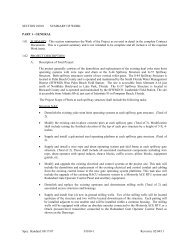
1. Demolition and replacement <strong>of</strong> the existing pump station intake channel steel sheet pile walls.<br />
In addition to the replacement <strong>of</strong> the existing steel sheet piling for the pump station intake a<br />
dedicated bypass channel shall be constructed using steel sheet piling to completely isolate the<br />
pump station intake from the bypass culvert inlet.<br />
2. Supply and install a fully automated debris collection system. The system shall include four<br />
front return mechanical rake units each <strong>of</strong> which are equipped with integrated debris racks. The<br />
system shall also include a belt conveyor unit to convey the collected debris to a new cast-inplace<br />
concrete debris bin.<br />
3. Construction <strong>of</strong> a new precast concrete debris collection system maintenance access bridge to<br />
span the width <strong>of</strong> the modified pump station intake channel.<br />
4. Demolition <strong>of</strong> the existing manually actuated slide gate at the bypass culvert inlet structure<br />
(Typ. <strong>of</strong> 1).<br />
5. Supply and install one, 96-inch motor actuated slide gate at the existing bypass culvert inlet<br />
structure. This task will also include the installation <strong>of</strong> a new gate position sensor.<br />
6. Demolition <strong>of</strong> the existing manually actuated flap gate and operator at the bypass culvert outlet<br />
structure (Typ. <strong>of</strong> 1).<br />
7. Supply and install one, 96-inch motor actuated combination gate at the existing bypass culvert<br />
outlet structure. This task shall include the modification <strong>of</strong> the existing bypass culvert outlet<br />
structure maintenance platform and standard railing/fencing, as indicated on the Drawings.<br />
This task will also include the installation <strong>of</strong> a new gate position sensor.<br />
8. Construction <strong>of</strong> new internal asphalt driveways to provide ingress and egress to the new<br />
maintenance access bridge. This task shall include all associated site grading, guardrails and<br />
other site improvements required to provide site drainage, bank stabilization and site security.<br />
9. Complete reconstruction <strong>of</strong> the existing asphalt parking, driveways and access roads with new<br />
full-depth asphalt pavement. This task shall include all associated site grading, guardrails and<br />
other site improvements required to provide site drainage, bank stabilization and site security.<br />
10. Complete reconstruction <strong>of</strong> the existing emulsified asphalt and rock levee access roads and<br />
driveway with new full-depth asphalt pavement. This task shall include all associated site<br />
grading, guardrails and other site improvements required to provide site drainage, bank<br />
stabilization and site security.<br />
11. Demolition and replacement <strong>of</strong> the existing dedicated pump intake bay debris racks (Typ. <strong>of</strong> 3).<br />
12. Maintenance dredging <strong>of</strong> the pump station intake channel to the original design elevation <strong>of</strong><br />
1.5-ft (NGVD29).<br />
13. Replacement <strong>of</strong> existing onsite rain gauge to accommodate the proposed site improvements.<br />
14. Relocation <strong>of</strong> the existing bearing water lubrication system. The system shall be relocated to the<br />
new pump station intake channel steel sheet pile wall cap. This item includes the replacement <strong>of</strong><br />
some existing items in the system with new items, as shown on the Drawings.<br />
15. Relocation <strong>of</strong> existing site irrigation pump. The pump shall be relocated to the new pump<br />
station intake channel steel sheet pile wall cap. This item includes the replacement <strong>of</strong> some<br />
existing items in the system with new items, as shown on the Drawings.<br />
Spec. Standard: 08/17/07 <strong>01010</strong>-1 Revision: 02/15/12
16. Demolition and replacement <strong>of</strong> the existing asphalt fuel tanker containment pad. The<br />
replacement pad shall be cast-in-place concrete.<br />
17. Installation <strong>of</strong> security fencing around the existing fuel storage tank spill containment pad and<br />
along the pump station intake channel steel sheet pile wall.<br />
18. Supply and install the fall protection prevention devices indicated on the Drawings to meet<br />
current DISTRICT standards.<br />
19. Modification and upgrades to the existing site electrical and control systems to accommodate<br />
the proposed facility improvements.<br />
Pump Station S-131<br />
1. Demolition and replacement <strong>of</strong> the existing pump station intake channel steel sheet pile walls.<br />
In addition to the replacement <strong>of</strong> the existing steel sheet piling for the pump station intake a<br />
dedicated bypass channel shall be constructed using steel sheet piling to completely isolate the<br />
pump station intake from the bypass culvert inlet.<br />
2. Supply and install a fully automated debris collection system. The system shall include three<br />
front return mechanical rake units each <strong>of</strong> which are equipped with integrated debris racks. The<br />
system shall also include a belt conveyor unit to convey the collected debris to a new cast-inplace<br />
concrete debris bin.<br />
3. Construction <strong>of</strong> a new precast concrete debris collection system maintenance access bridge to<br />
span the width <strong>of</strong> the modified pump station intake channel.<br />
4. Demolition <strong>of</strong> the existing manually actuated slide gate at the bypass culvert inlet structure<br />
(Typ. <strong>of</strong> 1).<br />
5. Supply and install one, 96-inch motor actuated slide gate at the existing bypass culvert inlet<br />
structure. This task will also include the installation <strong>of</strong> a new gate position sensor.<br />
6. Demolition <strong>of</strong> the existing manually actuated flap gate and operator at the bypass culvert outlet<br />
structure (Typ. <strong>of</strong> 1).<br />
7. Supply and install one, 96-inch motor actuated combination gate at the existing bypass culvert<br />
outlet structure. This task shall include the modification <strong>of</strong> the existing bypass culvert outlet<br />
structure maintenance platform and standard railing/fencing, as indicated on the Drawings. This<br />
task will also include the installation <strong>of</strong> a new gate position sensor.<br />
8. Demolition and replacement <strong>of</strong> the existing onsite septic tank and drainfield. The replacement<br />
septic system shall include a prefabricated simplex lift station, pre-cast concrete septic tank,<br />
dosing tank, distribution box and absorption drainfield.<br />
9. Construction <strong>of</strong> new internal asphalt driveways to provide ingress and egress to the new<br />
maintenance access bridge. This task shall include all associated site grading, guardrails and<br />
other site improvements required to provide site drainage, bank stabilization and site security.<br />
10. Complete reconstruction <strong>of</strong> the existing asphalt parking, driveways and access roads with new<br />
full-depth asphalt pavement. This task shall include all associated site grading, guardrails and<br />
other site improvements required to provide site drainage, bank stabilization and site security.<br />
11. Complete reconstruction <strong>of</strong> the existing emulsified asphalt and rock levee access roads and<br />
driveway with new full-depth asphalt pavement. This task shall include all associated site<br />
grading, guardrails and other site improvements required to provide site drainage, bank<br />
stabilization and site security.<br />
12. Demolition and replacement <strong>of</strong> the existing dedicated pump intake bay debris racks (Typ. <strong>of</strong> 2).<br />
13. Maintenance dredging <strong>of</strong> the pump station intake channel to the original design elevation <strong>of</strong><br />
1.5-ft (NGVD29).<br />
14. Relocation <strong>of</strong> the existing bearing water lubrication system. The system shall be relocated to the<br />
new pump station intake channel steel sheet pile wall cap. This item includes the replacement <strong>of</strong><br />
some existing items in the system with new items, as shown on the Drawings.<br />
15. Relocation <strong>of</strong> existing site irrigation pump. The pump shall be relocated to the new pump<br />
station intake channel steel sheet pile wall cap. This item includes the replacement <strong>of</strong> some<br />
existing items in the system with new items, as shown on the Drawings.<br />
Spec. Standard: 08/17/07 <strong>01010</strong>-2 Revision: 02/15/12
16. Demolition and replacement <strong>of</strong> the existing asphalt fuel tanker containment pad. The<br />
replacement pad shall be cast-in-place concrete.<br />
17. Installation <strong>of</strong> security fencing around the existing fuel storage tank spill containment pad and<br />
along the pump station intake channel steel sheet pile wall.<br />
18. Supply and install the fall protection prevention devices indicated on the Drawings to meet<br />
current DISTRICT standards. Fall protection devices shall also be installed at the existing boat<br />
lock structure.<br />
19. Modification and upgrades to the existing site electrical and control systems to accommodate<br />
the proposed facility improvements.<br />
B. The historical water level elevations (NGVD 29) for the intake and outlet water bodies at each <strong>of</strong> the<br />
Pump Station sites are as follows:<br />
1. Pump Station S-129<br />
a. Intake Channel (Rim Canal) normal water surface pumping elevation: 12.75-13.5ft<br />
b. Intake Channel (Rim Canal) minimum water surface elevation: 9.71ft (2008)<br />
c. Intake Channel (Rim Canal) maximum water surface elevation: 14.41ft (1994)<br />
d. Intake Channel (Rim Canal) standard project flood water surface elevation: 17.0 ft<br />
e. Outlet Structure (Lake Okeechobee) normal water surface pumping elevation: 15.5-17.5ft<br />
f. Outlet Structure (Lake Okeechobee) minimum water surface non-pumping elevation: 9.4ft<br />
g. Outlet Structure (Lake Okeechobee) maximum water surface pumping elevation: 17.7ft<br />
h. Outlet Structure (Lake Okeechobee) standard project flood elevation: 23.5ft<br />
2. Pump Station S-131<br />
a. Intake Channel (Rim Canal) normal water surface pumping elevation: 12.75-13.5ft<br />
b. Intake Channel (Rim Canal) minimum water surface elevation: 10.121ft (2007)<br />
c. Intake Channel (Rim Canal) maximum water surface elevation: 14.38ft (1994)<br />
d. Intake Channel (Rim Canal) standard project flood water surface elevation: 17.0 ft<br />
e. Outlet Structure (Lake Okeechobee) normal water surface pumping elevation: 15.5-17.5ft<br />
f. Outlet Structure (Lake Okeechobee) minimum water surface non-pumping elevation: 9.4ft<br />
g. Outlet Structure (Lake Okeechobee) maximum water surface pumping elevation: 17.7ft<br />
h. Outlet Structure (Lake Okeechobee) standard project flood elevation: 23.5ft<br />
1.03 RELATED CONTRACT ACTIVITIES:<br />
A. The CONTRACTOR shall provide adequate bank protection/stabilization to protect the general public<br />
as well as the job site. The CONTRACTOR shall revegetate all embankments after grading.<br />
CONTRACTOR shall submit an embankment protection plan for DISTRICT approval.<br />
1.04 WORK PERFORMED BY OTHERS:<br />
A. The CONTRACTOR will be responsible for the performance <strong>of</strong> all work associated with the project.<br />
1.05 CONTRACTOR'S USE OF PREMISES: See General Terms & Conditions Article 6.11.<br />
A. During construction activities, the CONTRACTOR shall be responsible for maintaining all access<br />
roads in good condition, including grading and drainage. See General Terms & Conditions Article<br />
6.13.<br />
B. The CONTRACTOR shall ensure that all construction equipment crossing the DISTRICT bridges to<br />
access the following pump station structures shall not exceed the maximum rating shown in the<br />
tabulation. The CONTRACTOR shall verify the actual condition <strong>of</strong> the access bridges and provide<br />
signed and sealed certifications indicating that the construction equipment crossing the bridges will not<br />
adversely impact the structural integrity <strong>of</strong> the bridges.<br />
Spec. Standard: 08/17/07 <strong>01010</strong>-3 Revision: 02/15/12
Structure<br />
Pump Station S-129<br />
Pump Station S-131<br />
Rating<br />
HS-20<br />
HS-20<br />
It shall be the CONTRACTOR’S sole responsibility to repair all damages to the bridges which occur<br />
as a result <strong>of</strong> construction activities.<br />
1.06 DISTRICT'S USE OF PREMISES:<br />
A. Partial DISTRICT Occupancy: The DISTRICT reserves the right to place and install equipment in<br />
areas <strong>of</strong> the Project, prior to Substantial Completion provided that such occupancy does not interfere<br />
with completion <strong>of</strong> the <strong>Work</strong>. Such placing <strong>of</strong> equipment and partial occupancy shall not constitute<br />
acceptance <strong>of</strong> the <strong>Work</strong>.<br />
B. Pump Station Operation: The CONTRACTOR is specifically advised that Pump Station S-129 and S-<br />
131 are flood control structures which are typically operated prior to, during and after periods <strong>of</strong><br />
inclement weather or intermittently as required to perform normal routine maintenance. The<br />
DISTRICT reserves the right to operate and maintain each pump station site at all times. The<br />
CONTRACTOR shall not limit or otherwise restrict the DISTRICT’s ability to properly operate each<br />
pump station. The CONTRACTOR will be required to coordinate with the DISTRICT as required to<br />
minimize any and all construction impacts to the pump station operation and functionality.<br />
1.07 WORK SEQUENCE, COORDINATION ACTIVITIES AND SCHEDULED DATES:<br />
A. General: The CONTRACTOR will coordinate its work with other adjacent contractors, landowners<br />
and DISTRICT activities, with specific attention to access and staging areas. Construction sequence<br />
shall be determined by CONTRACTOR subject to the following needs for continuous access and<br />
operation by others.<br />
1. All site work and construction activities shall be substantially completed within 700 days after<br />
the issuance date <strong>of</strong> the Notice to Proceed and be completed and ready for final payment within<br />
790 days after the issuance date <strong>of</strong> the Notice to Proceed.<br />
B. Suggested Construction Sequence: Where specific coordination is required to mitigate impacts to the<br />
normal operation <strong>of</strong> the pump station(s) and as required to perform specific detailed tasks suggested<br />
sequences <strong>of</strong> construction have been prepared by the Design Engineer and are presented within the<br />
Contract Documents. CONTRACTOR may suggest modifications to the sequences provided the<br />
access and operation requirements are satisfied and compliance with the overall contract period is<br />
achieved. Regardless <strong>of</strong> whether or not specific sequences have been suggested all work shall be<br />
sequenced and completed as required to minimize the impacts to the operation and functionality <strong>of</strong><br />
each pump station site.<br />
C. Dewatering <strong>Work</strong> Restrictions: At Pump Station S-129 the Phase 1 dewatering work that impacts the<br />
bypass channel flow capacity shall only be performed during the Dry Season (December 1 st through<br />
April 30th). At Pump Station S-131 the Phase 1, 2 and 3 dewatering work that impacts the flow<br />
capacity <strong>of</strong> the bypass channel and/or Pump Bay #1 shall only be performed during the Dry Season<br />
(December 1 st through April 30th). If the DISTRICT determines that flow capacity at any <strong>of</strong> these<br />
locations is needed during the Dry Season, it may direct the CONTRACTOR to temporarily dismantle<br />
some or all <strong>of</strong> the c<strong>of</strong>ferdam structure and suspend the portion <strong>of</strong> the work dependent on the c<strong>of</strong>ferdam<br />
system. In the event such a suspension <strong>of</strong> work by the DISTRICT is deemed by the DISTRICT in its<br />
sole discretion to be unreasonable, then Article 15 <strong>of</strong> the “General Terms and Conditions” may be<br />
applied.<br />
1.08 COPIES OF DOCUMENTS: See General Terms & Conditions Article 2.02<br />
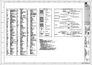
1.09 LIST OF DRAWINGS:<br />
A. Contract Drawings: 143 Total Sheets, grouped as follows:<br />
1. General Sheets<br />
2. Civil Sheets<br />
Spec. Standard: 08/17/07 <strong>01010</strong>-4 Revision: 02/15/12
3. Structural Sheets<br />
4. Mechanical Sheets<br />
5. Electrical Sheets<br />
B. Reference Materials:<br />
1. The following reference materials are included as part <strong>of</strong> this solicitation:<br />
<br />
<br />
Geotechnical Engineering Report for Proposed Improvements to North Shore Trash<br />
Rakes Pump Station S-129 Site, Universal Engineering Sciences, <strong>Inc</strong>., June 28, 2010<br />
Geotechnical Engineering Report for Proposed Improvements to North Shore Trash<br />
Rakes Pump Station S-131 Site, Universal Engineering Sciences, <strong>Inc</strong>., June 28, 2010<br />
The CONTRACTOR is specifically advised that these materials are for reference only, are<br />
provided as-is, are not contractual documents, and do not replace the CONTRACTOR’s due<br />
diligence in bid preparation.<br />
END OF SECTION<br />
Spec. Standard: 08/17/07 <strong>01010</strong>-5 Revision: 02/15/12
SECTION 01015<br />
DEFINITIONS AND STANDARDS<br />
PART 1 - GENERAL<br />
1.01 SCOPE:<br />
A. Definitions:<br />
1. A substantial amount <strong>of</strong> specification language constitutes definitions for terms found in other<br />
areas <strong>of</strong> Contract Documents including drawings which must be recognized as diagrammatic in<br />
nature and not completely descriptive <strong>of</strong> requirements indicated.<br />
2. Certain terms used in the Contract Documents are defined in the General Terms & Conditions.<br />
Definitions and explanations are not necessarily either complete or exclusive but are general for<br />
the work.<br />
3. The term “DISTRICT”, as defined in the General Terms & Conditions and used in these<br />
specifications, is further defined as the District or District’s authorized representative, which<br />
may include, but is not limited to, the Design Engineer or Construction Manager.<br />
B. General Requirements: General requirements are the provisions or requirements <strong>of</strong> Division 1 sections<br />
which apply to the entire work <strong>of</strong> the Contract.<br />
1.02 FORMAT AND SPECIFICATION EXPLANATIONS:<br />
A. Format Explanation: The format <strong>of</strong> principal portions <strong>of</strong> these specifications can be described as<br />
follows, although other portions may not fully comply and no particular significance will be attached<br />
to such compliance or noncompliance.<br />
1. Sections and Divisions: For convenience, basic unit <strong>of</strong> specification text is a "section", each<br />
unit <strong>of</strong> which is named and numbered. These are organized into related families <strong>of</strong> sections,<br />
and various families <strong>of</strong> sections are organized into "divisions", which are recognized as the<br />
present industry consensus on uniform organization and sequencing <strong>of</strong> specifications. The<br />
section title is not intended to limit meaning or content <strong>of</strong> section, nor to be fully descriptive <strong>of</strong><br />
requirements specified therein, nor to be an integral part <strong>of</strong> text.<br />
2. Section Numbering: Used for identification and to facilitate cross-references in contract<br />
documents. Sections are placed in numeric sequence; however, numbering sequence is not<br />
complete, and listing <strong>of</strong> sections in Table <strong>of</strong> Contents at beginning <strong>of</strong> Contract Documents must<br />
be consulted to determine numbers and names <strong>of</strong> specification sections in these Contract<br />
Documents.<br />
3. Page Numbering: Numbered independently for each section. Section number is shown with<br />
page number at bottom <strong>of</strong> each page to facilitate location <strong>of</strong> text.<br />
4. Parts: Each section <strong>of</strong> these specifications generally has been subdivided into three (3) basic<br />
parts for uniformity and convenience (Part 1 "General", Part 2 "Products", and Part 3<br />
"Execution"). These parts do not limit the meaning <strong>of</strong> text within. Some sections may not<br />
contain all three parts when not applicable, or may contain more than three parts to add clarity<br />
to organization <strong>of</strong> section.<br />
5. Imperative Language: Used generally in specifications. Except as otherwise indicated,<br />
requirements expressed imperatively are to be performed by the CONTRACTOR. For clarity<br />
<strong>of</strong> reading, at certain locations contrasting subjective language is used to describe<br />
responsibilities which must be fulfilled indirectly by the CONTRACTOR or, when so noted, by<br />
others.<br />
6. Specialists, Assignments: In certain instances, specification text requires that specific work be<br />
assigned to specialists or expert entities who must be engaged for performance <strong>of</strong> those units <strong>of</strong><br />
work. These must be recognized as special requirements over which the CONTRACTOR has<br />
Spec. Standard: 01/11/07 01015-1 Revision: 02/15/12
no choice or option. These assignments must not be confused with, and are not intended to<br />
interfere with, normal application <strong>of</strong> regulations, union jurisdictions and similar conventions.<br />
Nevertheless final responsibility for fulfillment <strong>of</strong> the entire set <strong>of</strong> requirements remains with<br />
the CONTRACTOR.<br />
7. Trades: Except as otherwise specified or indicated, the use <strong>of</strong> titles such as "carpentry" in<br />
specification text, implies neither that the work must be performed by an accredited or<br />
unionized tradesperson <strong>of</strong> corresponding generic name (such as "carpenter"), nor that specified<br />
requirements apply exclusively to work by tradespersons <strong>of</strong> that corresponding generic name.<br />
B. Specification Content: Because <strong>of</strong> methods by which this project specification has been produced,<br />
certain general characteristics <strong>of</strong> contents and conventions in use <strong>of</strong> language are explained as follows:<br />
1. Specifying Methods: The techniques or methods <strong>of</strong> specifying requirements varies throughout<br />
text, and may include "prescriptive", "compliance with standards", "performance",<br />
"proprietary", or a combination <strong>of</strong> these. The method used for specifying one unit <strong>of</strong> work has<br />
no bearing on requirements for another unit <strong>of</strong> work.<br />
2. Overlapping and Conflicting Requirements: Where compliance with two (2) or more industry<br />
standards or sets <strong>of</strong> requirements is specified, and overlapping <strong>of</strong> those different standards or<br />
requirements establishes different or conflicting minimums or levels <strong>of</strong> quality, notify the<br />
DISTRICT for a decision as specified in the General Terms & Conditions. The Contractor is<br />
specifically advised, however, that in general the more stringent <strong>of</strong> the conflicting standards or<br />
requirements shall be required. Therefore, the Contractor shall not receive additional<br />
compensation, under any circumstance, for the performance and/or completion <strong>of</strong> the work in<br />
accordance with the more stringent standard or requirement.<br />
3. Abbreviations: Throughout the Contract Documents are abbreviations implying words and<br />
meanings which will be appropriately interpreted. Specific abbreviations have been<br />
established, principally for lengthy technical terminology, and in conjunction with coordination<br />
<strong>of</strong> specification requirements, with notations on drawings and in schedules. These are normally<br />
defined at first instance <strong>of</strong> use. Organizational and association names and titles <strong>of</strong> general<br />
standards are also abbreviated.<br />
1.03 DRAWING SYMBOLS: Except as otherwise indicated, graphic symbols used on Drawings are those<br />
symbols recognized in the construction industry for purposes indicated. Refer instances <strong>of</strong> uncertainty to the<br />
DISTRICT for clarification.<br />
1.04 INDUSTRY STANDARDS - APPLICABILITY: Applicable standards <strong>of</strong> construction industry have the<br />
same force and effect, and are made a part <strong>of</strong> Contract Documents by reference, as if copied directly into the<br />
Contract Documents, or as if published copies were bound herewith. Referenced standards referenced<br />
directly in the Contract Documents or by governing regulations have precedence over non-referenced<br />
standards which are recognized in industry for applicability to work.<br />
END OF SECTION<br />
Spec. Standard: 01/11/07 01015-2 Revision: 02/15/12
SECTION 01020<br />
MEASUREMENT AND PAYMENT<br />
PART 1 - GENERAL<br />
1.01 LUMP SUM CONTRACT: Unless indicated on the Contract Documents, all work indicated on the Contract<br />
Drawings and specified in the Bid Documents and Contract shall be included in the Contract Sum indicated<br />
on the Bid Form. The following is a description <strong>of</strong> the <strong>Work</strong> listed in the Bid Form and is not intended to be<br />
complete and all-inclusive <strong>of</strong> the required work items. The <strong>Work</strong> shall include all miscellaneous and ancillary<br />
items necessary to construct a complete and functional Project.<br />
A. Bid Item A: North Shore Pump Station S-129 and S-131 Trash Rake Upgrades and Site Improvements.<br />
1.02 BASIS FOR PAYMENTS: The above descriptions generally outline the scope <strong>of</strong> work required for those<br />
elements <strong>of</strong> the <strong>Work</strong> to be paid for under each lump sum item listed in the Bid Form. Those lump sum<br />
amounts shall be further distributed in accordance with subvalues identified in the approved Cost Loaded<br />
Schedule specified in Section 01310 – Construction Schedules and the GENERAL TERMS &<br />
CONDITIONS, Article 2.07.<br />
A. The CONTRACTOR shall have ninety (90) business days after Contract execution, to produce the<br />
required Insurance Declaration Page <strong>of</strong> Policy for the insurance requirements set forth in the General<br />
Terms & Conditions, and the Insurance Requirements Checklist. The DISTRICT may refuse to make<br />
whole or part <strong>of</strong> any payment if the CONTRACTOR fails to submit the required Insurance Policy<br />
Declaration Page as stated in the Contract.<br />
1.03 PAYMENTS: Payments shall be in accordance with the provisions <strong>of</strong> the GENERAL TERMS &<br />
CONDITIONS, Article 14.<br />
END OF SECTION<br />
Spec. Standard: 02/17/12 01020-1 Revision: 02/21/12
SECTION 01045<br />
CUTTING AND PATCHING<br />
PART 1 - GENERAL<br />
1.01 WORK INCLUDED:<br />
A. Definition: "Cutting and patching" includes cutting into existing construction to provide for the<br />
installation or performance <strong>of</strong> other work and subsequent fitting and patching required to restore<br />
surfaces to their original condition.<br />
1. Cutting and patching is performed for coordination <strong>of</strong> the work, to uncover work for access or<br />
inspection, to obtain samples for testing, to permit alterations to be performed or for other<br />
similar purposes.<br />
2. Cutting and patching performed during the manufacture <strong>of</strong> products, or during the initial<br />
fabrication, erection or installation processes is not considered to be "cutting and patching"<br />
under this definition. Drilling <strong>of</strong> holes to install fasteners and similar operations are also not<br />
considered to be "cutting and patching."<br />
B. Refer to other sections <strong>of</strong> these specifications and the Drawings for specific cutting and patching<br />
requirements and limitations applicable to individual units <strong>of</strong> work.<br />
1.02 SUBMITTALS:<br />
1. Unless otherwise specified, requirements <strong>of</strong> this section apply to mechanical and electrical<br />
work.<br />
2. Refer to Division 15 and Division 16 sections for additional requirements and limitations on<br />
cutting and patching <strong>of</strong> mechanical and electrical work.<br />
A. Procedural Proposal for Cutting and Patching: DISTRICT approval <strong>of</strong> all cutting and patching work<br />
tasks will be required. Contractor shall submit the proposed procedures for the work tasks well in<br />
advance (min. 30 days) <strong>of</strong> the proposed date the work will be performed and request approval to<br />
proceed. <strong>Inc</strong>lude the following information, as applicable, in the submittal:<br />
1. Describe nature <strong>of</strong> the work and how it is to be performed, indicating why cutting and patching<br />
cannot be avoided.<br />
2. Describe anticipated results <strong>of</strong> the work in terms <strong>of</strong> changes to existing work, including<br />
structural, operational and visual changes as well as other significant elements.<br />
3. List products to be used and firms that will perform work.<br />
4. Give dates when work is expected to be performed.<br />
5. List utilities that will be disturbed or otherwise be affected by work, including those that will be<br />
relocated and those that will be out-<strong>of</strong>-service temporarily.<br />
a. Indicate how long utility service will be disrupted.<br />
6. Where cutting and patching <strong>of</strong> structural work involves the addition <strong>of</strong> reinforcement, submit<br />
details and engineering calculations to show how that reinforcement is integrated with original<br />
structure to satisfy requirements.<br />
B. Approval by the DISTRICT to proceed with cutting and patching work does not waive the<br />
DISTRICT'S right to later require complete removal and replacement <strong>of</strong> work found to be cut and<br />
patched in an unsatisfactory manner.<br />
Spec. Standard: 11/27/06 01045-1 Revision: 02/15/12
1.03 QUALITY ASSURANCE:<br />
A. Requirements for Structural <strong>Work</strong>: Do not cut and patch structural work in a manner that would result<br />
in a reduction <strong>of</strong> load-carrying capacity or <strong>of</strong> load-deflection ratio.<br />
B. Operational and Safety Limitations: Do not cut and patch operational elements or safety related<br />
components in a manner that would result in a reduction <strong>of</strong> their capacity to perform in the manner<br />
intended, including energy performance, or that would result in increased maintenance, or decreased<br />
operational life or decreased safety.<br />
C. Visual Requirements: Do not cut and patch work exposed on any building's exterior or in its occupied<br />
spaces, in a manner that would, in the DISTRICT'S opinion, result in lessening the building's aesthetic<br />
qualities.<br />
PART 2 - PRODUCTS<br />
2.01 MATERIALS:<br />
1. Do not cut and patch work in a manner that would result in substantial visual evidence <strong>of</strong> cut<br />
and patch work.<br />
2. Remove and replace work judged by the DISTRICT to be cut and patched in a visually<br />
unsatisfactory manner.<br />
3. Retain the original installer or fabricator if possible, or another recognized experienced and<br />
specialized firm for cutting and patching.<br />
A. General: Except as otherwise indicated, or as directed by the DISTRICT, use materials for cutting and<br />
patching that are identical to existing materials.<br />
B. If identical materials are not available or cannot be used, use materials that match existing adjacent<br />
surfaces to the fullest extent possible with regard to visual effect.<br />
C. Use materials for cutting and patching that will result in equal-or-better performance characteristics.<br />
PART 3 - EXECUTION<br />
3.01 INSPECTION:<br />
A. Before cutting, examine the surfaces to be cut and patched and the conditions under which the work is<br />
to be performed. If unsafe or otherwise unsatisfactory conditions are encountered, take corrective<br />
action before proceeding with the work.<br />
B. Coordinate layout <strong>of</strong> the work and resolve potential conflicts before proceeding with the work.<br />
3.02 PREPARATION:<br />
A. Temporary Support: To prevent failure, provide temporary support <strong>of</strong> work to be cut.<br />
B. Protection: Protect other work during cutting and patching to prevent damage. Provide protection<br />
from adverse weather conditions for that part <strong>of</strong> the project that may be exposed during cutting and<br />
patching operations.<br />
1. Avoid interference with use <strong>of</strong> adjacent facilities or interruption <strong>of</strong> free passage to adjacent<br />
facilities.<br />
2. Take precautions not to cut existing pipes, conduits or ducts serving the building but scheduled<br />
to be relocated until provisions have been made to by-pass them. Coordinate with the<br />
DISTRICT.<br />
Spec. Standard: 11/27/06 01045-2 Revision: 02/15/12
3.03 PERFORMANCE:<br />
A. General: Employ skilled workmen to perform cutting and patching work. Except as otherwise<br />
indicated or as approved by the DISTRICT, proceed with cutting and patching at the earliest feasible<br />
time and complete work without delay.<br />
B. Cutting: Cut the work using methods that are least likely to damage work to be retained or adjoining<br />
work. Where possible, review proposed procedures with the original installer; comply with original<br />
installer's recommendations.<br />
1. General: Use hand or small power tools designed for sawing or grinding, not hammering and<br />
chopping, where cutting is required. Use <strong>of</strong> gasoline-powered tools will not be permitted in<br />
enclosed spaces.<br />
2. Cut through concrete and masonry using a cutting machine such as a carborundum saw or core<br />
drill to insure a neat hole.<br />
3. Cut holes and slots neatly to size required with minimum disturbance <strong>of</strong> adjacent work.<br />
4. Cut or drill from the exposed or finished side into concealed surfaces to avoid marring existing<br />
finished surfaces.<br />
5. Temporarily cover openings when not in use.<br />
C. By-pass utility services such as pipe and conduit, before cutting, where such utility services are shown<br />
or required to be removed, relocated or abandoned.<br />
D. Cut <strong>of</strong>f conduit and pipe in walls or partitions to be removed. After by-pass and cutting, cap, valve or<br />
plug and seal tight remaining portion <strong>of</strong> pipe and conduit to prevent entrance <strong>of</strong> moisture or other<br />
foreign matter.<br />
E. Patching: Patch with seams which are durable and as invisible as possible. Comply with specified<br />
tolerances for the work.<br />
3.04 CLEANING:<br />
1. Inspect and test patched areas to demonstrate integrity <strong>of</strong> work where feasible.<br />
2. Restore exposed finishes <strong>of</strong> patched areas and where necessary extend finish restoration into<br />
retained adjoining work in a manner which will eliminate evidence <strong>of</strong> patching and refinishing.<br />
3. Patch and repair floor and wall surfaces in the new space to provide an even surface <strong>of</strong> uniform<br />
color and appearance where removal <strong>of</strong> walls or partitions extends one finished area into<br />
another finished area.<br />
4. If necessary to achieve uniform color and appearance, remove existing floor and wall coverings<br />
and replace with new materials.<br />
5. Extend final paint coat over entire unbroken surface containing patch, after patched area has<br />
received prime and base coat where patch occurs in a smooth painted surface.<br />
6. Patch, repair or re-hang existing ceilings as necessary to provide an even plane surface <strong>of</strong><br />
uniform appearance.<br />
A. Thoroughly clean areas and spaces where work is performed or used as access to work. Remove<br />
completely paint, mortar, oils, putty and items <strong>of</strong> similar nature.<br />
B. Thoroughly clean piping, conduit and similar features before painting or other finishing is applied.<br />
C. Restore damaged pipe covering to its original condition.<br />
END OF SECTION<br />
Spec. Standard: 11/27/06 01045-3 Revision: 02/15/12
SECTION 01050<br />
FIELD ENGINEERING<br />
PART 1 - GENERAL (See General Terms & Conditions Article 4.05 "Reference Points.")<br />
1.01 The CONTRACTOR shall engage a licensed engineer <strong>of</strong> the discipline required, registered in the State <strong>of</strong><br />
Florida, to perform engineering services for temporary facilities including the design <strong>of</strong> shoring systems,<br />
shores, earth and water retaining systems, forms, temporary erection supports, and similar items provided by<br />
the CONTRACTOR as part <strong>of</strong> its means and methods <strong>of</strong> construction.<br />
The CONTRACTOR shall engage a pr<strong>of</strong>essional surveyor and mapper registered in the State <strong>of</strong> Florida to<br />
perform the necessary layout, survey control and monumentation.<br />
The CONTRACTOR shall provide one set <strong>of</strong> As-Built Drawings depicting all elevations in both NAVD88<br />
and NGVD29. The NGVD29 elevation shall be italicized, bracketed, and underscored.<br />
PART 2 - CONTRACTOR CONSTRUCTION STAKING<br />
2.01 DESCRIPTION: In connection with this <strong>Work</strong>, CONTRACTOR shall:<br />
A. Perform all construction layout and reference staking necessary for the proper control and satisfactory<br />
completion <strong>of</strong> the <strong>Work</strong>.<br />
B. Run a level circuit between vertical control points indicated to check plan benchmarks and establish<br />
new benchmarks where necessary.<br />
2.02 CONSTRUCTION REQUIREMENTS:<br />
A. The CONTRACTOR’S personnel performing the construction staking shall work under the direct<br />
supervision <strong>of</strong> a Florida registered engineer or Florida licensed land surveyor. Submit name and<br />
address <strong>of</strong> individual responsible for surveying to the DISTRICT prior to start <strong>of</strong> survey activities.<br />
B. The CONTRACTOR shall be solely and completely responsible for the accuracy <strong>of</strong> the line and grade<br />
<strong>of</strong> all features <strong>of</strong> the <strong>Work</strong>. Any errors or apparent discrepancies found in previous surveys, plans, or<br />
specifications shall be called to the attention <strong>of</strong> the DISTRICT by the CONTRACTOR for correction<br />
or interpretation prior to proceeding with the work.<br />
C. Field notes shall be kept in standard, bound field notebooks in a clear, orderly, and neat manner<br />
consistent with standard engineering practices.<br />
D. The CONTRACTOR shall be responsible for the placement and preservation <strong>of</strong> adequate ties and<br />
reference to all control points, whether established by him or found on the project, necessary for the<br />
accurate reestablishment <strong>of</strong> all base lines or centerlines shown on the Plans. All land ties (i.e. section<br />
corners, fractional section corners, and similar items) that may be lost or destroyed during construction<br />
shall be carefully referenced and replaced.<br />
E. The supervision <strong>of</strong> the CONTRACTOR’S construction engineering personnel shall be the<br />
responsibility <strong>of</strong> the CONTRACTOR; any deficient engineering layout or construction work which<br />
may be the result <strong>of</strong> inaccuracies in his staking operations or <strong>of</strong> his failure to report inaccuracies found<br />
in work previously done by the Design Engineer shall be corrected at the expense <strong>of</strong> the<br />
CONTRACTOR.<br />
F. Station Identification: On linear elements <strong>of</strong> construction (such as levees, canals, and similar items)<br />
the CONTRACTOR shall place temporary identifying signs at intervals no greater than 500 feet using<br />
4-foot sections <strong>of</strong> 1-inch by 4-inch lumber driven into the ground. The signs shall identify the station<br />
at that location.<br />
Spec. Standard: 05/03/10 01050-1 Revision: 02/15/12
G. In order to expedite the commencement <strong>of</strong> construction operations, the staking operation may<br />
commence prior to the issuance <strong>of</strong> the Notice to Proceed. The CONTRACTOR shall obtain written<br />
approval <strong>of</strong> the DISTRICT prior to commencing staking.<br />
2.03 SURVEYING STANDARDS for stilling wells and water control structures:<br />
A. A permanent mark shall be established identifying the elevation measuring point on the rim <strong>of</strong> all<br />
stilling wells. A permanent noncorrosive plate or tag shall be attached to stilling wells with the<br />
measuring point elevation.<br />
1. All vertical elevations shall commence from a minimum <strong>of</strong> two National Geodetic Survey<br />
(NGS) second order or better published benchmarks.<br />
2. All elevations shall be established to NGS third order standards and certified to those standards<br />
by a Pr<strong>of</strong>essional Surveyor and Mapper registered in the state <strong>of</strong> Florida.<br />
3. All level runs shall be double run (forward and back) or looped into two NGS second order or<br />
better published benchmarks.<br />
4. A site benchmark shall be set if one does not exist. The benchmark shall consist <strong>of</strong> a minimum<br />
<strong>of</strong> two eighty pound bags <strong>of</strong> concrete mix, a ferrous piece <strong>of</strong> material able to be located with a<br />
magnetic locator, and a survey cap (supplied by the DISTRICT) stamped with the site<br />
designation.<br />
5. Permanent benchmarks shall be established in NAVD88 with the datum <strong>of</strong>fset for conversion to<br />
NGVD29. Datum <strong>of</strong>fsets shall be made using the DISTRICT’s vertical datum conversion<br />
application (VDCA) available on the web at http://my.sfwmd.gov/vdcaweb. The datum<br />
conversion to NGVD29 shall be made from the closest bench mark. The NGVD 29 conversions<br />
shall be accurate to 0.01 feet...<br />
6. State Plane Coordinates (NAD 83/99) shall be established at all stilling well and benchmark<br />
locations with a positional accuracy <strong>of</strong> +/- three feet.<br />
7. A DISTRICT benchmark description sheet shall be completed for each set benchmark.<br />
8. If there are no second order or better published benchmarks within six miles <strong>of</strong> the site, contact<br />
the DISTRICT Surveying Section representative at (561) 682-6688 prior to commencement.<br />
9. Contact the DISTRICT Survey Section prior to commencement to check for previously<br />
established site benchmarks that may be suitable to use.<br />
10. A listing <strong>of</strong> NGVD29 values associated with the Comprehensive Everglades Restoration Plan<br />
(CERP) Geodetic Vertical Control Network is available from the DISTRICT.<br />
B. All structures shall have a permanent benchmark mounted at a location as directed by the DISTRICT.<br />
The marker for the benchmark can be obtained from the DISTRICT Survey Section, (561) 682-6688.<br />
The Contractor shall only stamp or engrave the benchmark identification and not the elevation.<br />
C. The CONTRACTOR shall install two staff gauges, one permanent slide mounted staff gauge on<br />
concrete pile and set in NAVD 88, and one temporary staff gauge on timber pile and set in NGVD 29,<br />
at each location requiring a staff gauge. A 3” x 7” sign with 2” alphabet height shall be installed on top<br />
<strong>of</strong> each staff gauge to identify the NAVD 88 (white lettering on red background) or NGVD 29 (black<br />
lettering on white background) Datum.<br />
2.04 RECORDS AND SUBMITTALS:<br />
A. Submittal:<br />
1. Provide DISTRICT a copy <strong>of</strong> the designs described in Paragraph 1.01 signed and sealed by the<br />
licensed engineer.<br />
Spec. Standard: 05/03/10 01050-2 Revision: 02/15/12
2. Provide DISTRICT the data required for the individual responsible for layout and records as<br />
required in Paragraph 2.02 A.<br />
B. Records: At the end <strong>of</strong> the Project, submit to the DISTRICT a certified site survey showing<br />
coordinates and elevations <strong>of</strong> the completed <strong>Work</strong>. Submit a copy <strong>of</strong> the field notes required in<br />
Paragraph 2.02.C. These are part <strong>of</strong> the record documents required in SECTION 01700.<br />
C. Cross-sections: Canal and Levee cross-sections shall be submitted as specified in SECTION 02200.<br />
END OF SECTION<br />
Spec. Standard: 05/03/10 01050-3 Revision: 02/15/12
SECTION 01065<br />
PERMITS AND FEES<br />
PART 1 - GENERAL<br />
1.01 Unless otherwise specified, the CONTRACTOR shall obtain and pay for any permits and licenses related to<br />
his work as provided for in the General Terms & Conditions, except as otherwise provided herein.<br />
1.02 The CONTRACTOR will be issued copies <strong>of</strong> all permits obtained by the DISTRICT at the pre-construction<br />
conference. A copy <strong>of</strong> the permits shall be posted at the site at all times during construction. The<br />
CONTRACTOR shall be responsible for familiarizing himself with the permits and shall abide by the permit<br />
conditions at all times.<br />
1.03 The following permits have been or will be secured by the DISTRICT:<br />
A. U.S. Army Corp <strong>of</strong> Engineers – Nationwide Permit for Dredge and Fill.<br />
B. U.S. Army Corp <strong>of</strong> Engineers – Nationwide Permit the Installation <strong>of</strong> the Trash Rack and Collection<br />
System.<br />
C. Florida Department <strong>of</strong> Environmental Protection – General Permit (water quality certification) for all<br />
four pump stations as a permit modification to the Lake Okeechobee Operations Permit.<br />
The CONTRACTOR shall be solely responsible for obtaining any other permits which are not specifically<br />
indicated above and which are required to facilitate completion <strong>of</strong> the project in accordance with all Local,<br />
State and Federal regulatory agencies.<br />
1.04 <strong>Work</strong> shall be conducted, and shall result in construction <strong>of</strong> the improvements <strong>of</strong> this project, in full<br />
accordance with the conditions <strong>of</strong> the permits granted for the project.<br />
END OF SECTION<br />
Spec. Standard: 01/19/06 01065-1 Revision: 02/15/12
SECTION 01071<br />
STANDARD REFERENCES<br />
Wherever used in the project manual, the following abbreviations will have the meanings listed:<br />
AA<br />
Aluminum Association <strong>Inc</strong>orporated<br />
818 Connecticut Avenue, N.W.<br />
Washington, D.C. 20006<br />
AABC<br />
AAMA<br />
AASHTO<br />
ABMA<br />
ACI<br />
AEIC<br />
AFBMA<br />
AGA<br />
AGMA<br />
AHA<br />
AISC<br />
AISI<br />
Associated Air Balance Council<br />
1518 K Street N.W.<br />
Washington, D.C. 20005<br />
American Architectural Manufacturers Association<br />
2700 River Road, Suite 118<br />
Des Plaines, IL 60018<br />
American Association <strong>of</strong> State Highway and Transportation Officials<br />
444 North Capitol Street, N.W., Suite 225<br />
Washington, D.C. 20001<br />
American Bearing Manufacturers Association<br />
1101 Connecticut Avenue, N.W. Suite 700<br />
Washington, D.C. 20036<br />
American Concrete Institute<br />
P. O. Box 19150<br />
Detroit, MI<br />
Association <strong>of</strong> Edison Illuminating Companies<br />
51 East 42nd Street<br />
New York, NY 10017<br />
Anti-Friction Bearing Manufacturers Association<br />
American Gas Association<br />
8501 East Pleasant Valley Road<br />
Cleveland, OH 44131<br />
American Gear Manufacturer's Association<br />
1330 Massachusetts Avenue, N.W.<br />
Washington, D.C.<br />
American Hardboard Association<br />
520 N. Hicks Road<br />
Palatine, IL 60067<br />
American Institute <strong>of</strong> Steel Construction<br />
101 Park Avenue<br />
New York, NY 10017<br />
American Iron and Steel Institute<br />
1000 16th Street, N.W.<br />
Washington, D.C. 20036<br />
Spec. Standard: 04/09/06 01071-1 Revision: 02/15/12
AITC<br />
ALSC<br />
AMCA<br />
ANSI<br />
APA<br />
API<br />
ARI<br />
ASCE<br />
ASCII<br />
ASE<br />
ASHRAE<br />
ASME<br />
ASTM<br />
American Institute <strong>of</strong> Timber Construction<br />
333 West Hampden Avenue<br />
Englewood, CO 80110<br />
American Lumber Standards Committee<br />
P. O. Box 210<br />
Germantown, MD 20874<br />
Air Movement and Control Association, <strong>Inc</strong>.<br />
30 West University Drive<br />
Arlington Heights, IL 60004<br />
American National Standards Institute, <strong>Inc</strong>.<br />
1430 Broadway<br />
New York NY 10018<br />
American Plywood Association<br />
1119 A Street<br />
Tacoma, WA 98401<br />
American Petroleum Institute<br />
1801 K Street N.W.<br />
Washington, D.C. 20006<br />
Air-Conditioning and Refrigeration Institute<br />
1814 North Fort Myer Drive<br />
Arlington, VA 22209<br />
American Society <strong>of</strong> Civil Engineers<br />
345 East 47th Street<br />
New York, NY 10017<br />
American Standard Code for Information Interchange<br />
United States <strong>of</strong> America Standards Institute<br />
10 East 40th Street<br />
New York, NY 10016<br />
American Standard Safety Code for Elevators,<br />
Code Dumbwaiter and Escalators<br />
American National Standards Institute<br />
1430 Broadway<br />
New York, NY 10018<br />
American Society <strong>of</strong> Heating, Refrigeration and Air Conditioning Engineers<br />
United Engineering Center<br />
345 East 47th Street<br />
New York, NY 10017<br />
American Society <strong>of</strong> Mechanical Engineers<br />
345 East 47th Street<br />
New York, NY 10017<br />
American Society for Testing and Materials<br />
1916 Race Street<br />
Philadelphia, PA 19103<br />
Spec. Standard: 04/09/06 01071-2 Revision: 02/15/12
AWPA<br />
AWPB<br />
AWPI<br />
AWI<br />
AWS<br />
AWWA<br />
BHMA<br />
BOCA<br />
CBM<br />
CMAA<br />
CRSI<br />
CSA<br />
DEMA<br />
American Wood Preservers Association<br />
1625 Eye Street<br />
Washington, D.C. 20006<br />
American Wood Preservers Bureau<br />
7962 Conell Court<br />
P. O. Box 5283<br />
Lorton, VA 22079<br />
American Wood Preservers Institute<br />
2750 Prosperity Avenue, Suite 550<br />
Fairfax, VA 22031-4312<br />
Architectural Woodwork Institute<br />
1952 Isaac Newton Square West<br />
Reston, VA 20190<br />
American Welding Society<br />
2501 N.W. 7th Street<br />
Miami, FL 33125<br />
American Water <strong>Work</strong>s Association<br />
6666 West Quincy Avenue<br />
Denver, CO 80235<br />
Builders Hardware Manufacturers Association<br />
355 Lexington Avenue, 17 th Floor<br />
New York, NY 10017<br />
Building Officials and Code Administrators<br />
17926 Halstead<br />
Homewood, IL 60430<br />
Certified Ballast Manufacturers<br />
2120 Keith Building<br />
Cleveland, OH 44115<br />
Crane Manufacturers Association <strong>of</strong> America, <strong>Inc</strong>.<br />
(Formerly called: Overhead Electrical Crane Institute) (OECI)<br />
1326 Freeport Road<br />
Pittsburgh, PA 15238<br />
Concrete Reinforcing Steel Institute<br />
180 North La Salle Street<br />
Chicago, IL 60601<br />
Canadian Standards Association<br />
178 Rexdale Boulevard<br />
Rexdale, Ontario, M9W IR3, Canada<br />
Diesel Engine Manufacturer's Association<br />
122 East 42nd Street<br />
New York, NY 10017<br />
Spec. Standard: 04/09/06 01071-3 Revision: 02/15/12
DHI<br />
DIS<br />
EEI<br />
EIA<br />
EJMA<br />
EPA<br />
Door Hardware Institute<br />
7711 Old Springhouse Road<br />
McLean, VA 22102<br />
Division <strong>of</strong> Industrial Safety<br />
California Department <strong>of</strong> Industrial Relations<br />
2422 Arden Way<br />
Sacramento, CA 95825<br />
Edison Electric Institute<br />
90 Park Avenue<br />
New York, NY 10016<br />
Electronic Industries Association<br />
2001 Eye Street, N.W.<br />
Washington, D.C. 20006<br />
Expansion Joint Manufacturer's Association<br />
25 North Broadway<br />
Tarrytown, NY 10591<br />
Environmental Protection Agency<br />
Region 4<br />
Sam Nunn Atlanta Federal Center<br />
61 Forsyth Street, SW<br />
Atlanta, GA 30303-3104<br />
ESO Electrical Safety Order, California Administrative Code, Title 8, Chap. 4, Subarticle 5<br />
Office <strong>of</strong> Procurement, Publications Section<br />
P. O. Box 20191<br />
8141 Elder Creek Road<br />
Sacramento, CA 95820<br />
FAC<br />
FEDSPEC<br />
FEDSTDS<br />
FM<br />
GANA<br />
HEI<br />
Florida Administrative Code<br />
Federal Specifications<br />
General Services Administration Specification and Consumer Information<br />
Distribution Branch<br />
Washington Navy Yard, Bldg. 197<br />
Washington, D.C. 20407<br />
Federal Standards (see FEDSPECS)<br />
Factory Mutual Research<br />
1151 Boston-Providence Turnpike<br />
Norwood, MA 02062<br />
Glass Association <strong>of</strong> North America<br />
2301 Tower Road<br />
Austin, TX 78703<br />
Heat Exchange Institute<br />
122 East 42nd Street<br />
New York, NY 10017<br />
Spec. Standard: 04/09/06 01071-4 Revision: 02/15/12
HI<br />
HPMA<br />
IAPMO<br />
ICBO<br />
ICEA<br />
ICRI<br />
IEEE<br />
IES<br />
ISA<br />
ISO<br />
JIC<br />
MFMA<br />
MILSPEC<br />
Hydraulic Institute<br />
1230 Keith Building<br />
Cleveland, OH 44115<br />
Hardwood Plywood Manufacturers Association<br />
1825 Michael Faraday Drive<br />
P. O. Box 2789<br />
Reston, VA 22090-2789<br />
International Association <strong>of</strong> Plumbing and Mechanical Officials<br />
5032 Alhambra Avenue<br />
Los Angeles, CA 90032<br />
International Conference <strong>of</strong> Building Officials<br />
5360 South <strong>Work</strong>man Mill Road<br />
Whittier, CA 90601<br />
Insulated Cable Engineers Association<br />
P. O. Box P<br />
South Yarmouth, MA 02664<br />
International Concrete Repair Institute<br />
3166 S. River Road, Suite 132<br />
Des Plaines, IL 60018<br />
Institute <strong>of</strong> Electrical and Electronics Engineers, <strong>Inc</strong>.<br />
345 East 47th Street<br />
New York, NY 10017<br />
Illuminating Engineering Society<br />
c/o United Engineering Center<br />
345 East 47th Street<br />
New York, NY 10017<br />
Instrument Society <strong>of</strong> America<br />
400 Stanwix Street<br />
Pittsburgh, PA 15222<br />
International Organization for Standardization<br />
1, ru de Varembé,<br />
Case postale 56<br />
CH-1211 Genna 20,<br />
Switzerland<br />
Joint Industrial Council<br />
7901 Westpark Drive<br />
McLean, VA 22101<br />
Metal Framing Manufacturers Association<br />
111 E. Wacker Drive<br />
Chicago, IL 60601<br />
Military Specifications<br />
Naval Publications and Forms Center<br />
5801 Tabor Avenue<br />
Philadelphia, PA 19120<br />
Spec. Standard: 04/09/06 01071-5 Revision: 02/15/12
MSS<br />
NAAMM<br />
NACE<br />
NEC<br />
NECA<br />
NELMA<br />
NEMA<br />
NESC<br />
NETA<br />
NFP<br />
NFPA<br />
NHLA<br />
NIST<br />
Manufacturers Standardization Society <strong>of</strong> the Valve and Fittings Industry, <strong>Inc</strong>.<br />
127 Park Avenue, N.E.<br />
Vienna, VA 22180<br />
National Association <strong>of</strong> Architectural Metal Manufacturers<br />
100 South Marion Street<br />
Oak Park, IL 60302<br />
National Association <strong>of</strong> Corrosion Engineers<br />
P. O. Box 986<br />
Katy, TX 77450<br />
National Electrical Code<br />
National Fire Protection Association<br />
470 Atlantic Avenue<br />
Boston, MA 02210<br />
National Electrical Contractors Association<br />
3 Bethesda Metro Center, Suite 1100<br />
Bethesda, MD 20814<br />
Northeastern Lumber Manufacturers Association, <strong>Inc</strong>.<br />
272 Turtle Road<br />
P. O. Box 87A<br />
Cumberland Center, ME 04021<br />
National Electrical Manufacturer's Association<br />
155 East 44th Street<br />
New York, NY 10017<br />
National Electric Safety Code<br />
American National Standards Institute<br />
1430 Broadway<br />
New York, NY 10018<br />
InterNational Electrical Testing Association<br />
P. O. Box 687<br />
Morrison, CO 80465<br />
National Forest Products Association (Formerly National Lumber<br />
Manufacturer's Association)<br />
1619 Massachusetts Avenue<br />
Washington, DC 20036<br />
National Fire Protection Association<br />
Batterymarch Park<br />
Quincy, MA 02269<br />
National Hardwood Lumber Association<br />
P. O. Box 34518<br />
Memphis, TN 38184-0518<br />
National Institute <strong>of</strong> Standards and Technology<br />
100 Bureau Drive, Suite 1070<br />
Gaithersburg, MD 20899-1070<br />
Spec. Standard: 04/09/06 01071-6 Revision: 02/15/12
NSF<br />
OSHA<br />
PCI<br />
PPIC<br />
RIS<br />
RLM<br />
RMA<br />
SAE<br />
SAMA<br />
SBC<br />
SMC<br />
SBCCI<br />
SCMA<br />
National Sanitation Foundation<br />
3475 Plymouth Road<br />
P. O. Box 1468<br />
Ann Arbor, MI 48106<br />
Occupational Safety and Health Act<br />
U.S. Department <strong>of</strong> Labor<br />
Occupational and Health Administration<br />
San Francisco Regional Office<br />
450 Golden Gate Avenue, Box 36017<br />
San Francisco, CA 94102<br />
Prestressed Concrete Institute<br />
175 W. Jackson Blvd., Suite 1859<br />
Chicago, IL 60604<br />
The Plumbing & Piping Industry Council, <strong>Inc</strong>.<br />
510 Shatto Place, Suite 402<br />
Los Angeles, CA 90020<br />
Redwood Inspection Service<br />
California Redwood Association<br />
405 Enfrente Dr., Suite 200<br />
Novato, CA 94949<br />
Reflector and Lamp Manufacturers Standard Institute<br />
Rubber Manufacturers Association<br />
1400 K Street<br />
Washington, D.C. 20005<br />
Society <strong>of</strong> Automotive Engineers<br />
2 Pennsylvania Plaza<br />
New York, NY 10001<br />
Scientific Apparatus Makers Association<br />
One Thomas Circle<br />
Washington, D.C. 20005<br />
Standard Building Code<br />
Published by SBCCI<br />
Standard Mechanical Code<br />
Published by SBCCI<br />
Southern Building Code Congress International<br />
1116 Brown-Marx Building<br />
Birmingham, AL 35203<br />
Southern Cypress Manufacturers Association<br />
805 Sterick Bldg.<br />
Memphis, TN 38103<br />
Spec. Standard: 04/09/06 01071-7 Revision: 02/15/12
SDI<br />
SMACNA<br />
SPC<br />
SPI<br />
SPIB<br />
SSPC<br />
SSPWC<br />
TEMA<br />
UL<br />
USBR<br />
USCOE<br />
WCLIB<br />
Steel Door Institute<br />
712 Lakewood Center N.<br />
14600 Detroit Avenue<br />
Cleveland, OH 44107<br />
Sheet Metal and Air Conditioning Contractors<br />
National Association, <strong>Inc</strong>.<br />
8224 Old Courthouse Road<br />
Tysons Corner Vienna, VA 22180<br />
Society for Protective Coatings<br />
40 24 th Street, 6 th Floor<br />
Pittsburgh, PA 15222<br />
Society <strong>of</strong> the Plastics Industry, <strong>Inc</strong>.<br />
1275 K Street NW, Suite 400<br />
Washington, D.C. 20005<br />
Southern Pine Inspection Bureau<br />
4709 Scenic Highway<br />
Pensacola, Fl 32504<br />
Steel Structures Painting Council<br />
4400 Fifth Avenue<br />
Pittsburgh, PA 15213<br />
Standard Specifications for Public <strong>Work</strong>s Construction<br />
Building News, <strong>Inc</strong>.<br />
3055 Overland Avenue<br />
Los Angeles, CA 90034<br />
Tubular Exchanger Manufacturer's Association<br />
331 Madison Avenue<br />
New York, NY 10017<br />
Underwriters Laboratories <strong>Inc</strong>.<br />
207 East Ohio Street<br />
Chicago, IL 60611<br />
Bureau <strong>of</strong> Reclamation<br />
U.S. Department <strong>of</strong> Interior<br />
Engineering and Research Center<br />
Denver Federal Center, Building 67<br />
Denver, CO 80225<br />
United States Corps <strong>of</strong> Army Engineers<br />
Jacksonville District<br />
P. O. Box 4970<br />
Jacksonville, FL 32232-0019<br />
West Coast Lumber Inspection Bureau<br />
6980 SW Varns Street<br />
P. O. Box 23145<br />
Portland, OR 97223<br />
Spec. Standard: 04/09/06 01071-8 Revision: 02/15/12
WWPA<br />
Western Wood Products Association<br />
(Formerly called: West Coast Lumbermen's Association (WCLA))<br />
Yeon Building<br />
Portland, OR 97204<br />
END OF SECTION<br />
Spec. Standard: 04/09/06 01071-9 Revision: 02/15/12
SECTION 01200<br />
PROJECT MEETINGS AND REPORTS<br />
PART 1 - GENERAL<br />
1.01 SUMMARY: This Section includes the following administrative and procedural requirements:<br />
A. Project Meetings:<br />
1. Preconstruction conference<br />
2. Progress meetings<br />
B. Schedules and Reports:<br />
1. Initial coordination submittals<br />
2. Construction progress schedule (See SECTION 01310 Construction Schedules)<br />
3. Special reports<br />
1.02 PROJECT MEETINGS:<br />
A. Pre-construction Conference<br />
1. The DISTRICT will administer a meeting within 10 days after the Effective Date <strong>of</strong> the<br />
Agreement, to review items stated in the following agenda and to establish a working<br />
understanding between the parties as to their relationships during conduct <strong>of</strong> the <strong>Work</strong>.<br />
2. Preconstruction conference shall be attended by:<br />
a. CONTRACTOR and his superintendent<br />
b. Representatives <strong>of</strong> principal Subcontractors and Suppliers<br />
c. Engineer and his Resident Project Representative if any<br />
d. DISTRICT or his representative<br />
e. Other affected parties determined by the DISTRICT<br />
3. Agenda:<br />
a. Projected construction schedules<br />
b. Critical <strong>Work</strong> sequencing<br />
c. Designation <strong>of</strong> responsible personnel<br />
d. Project coordination<br />
e. Procedures and Processing <strong>of</strong>:<br />
i. Field decisions<br />
ii.<br />
iii.<br />
iv.<br />
Substitutions<br />
Submittals<br />
Change Orders<br />
v. Applications for payment<br />
f. Procedures for testing<br />
g. Procedures for maintaining record documents<br />
h. Use <strong>of</strong> Premises:<br />
i. Office, work and storage areas<br />
Spec. Standard: 11/27/06 01200-1 Revision: 02/15/12
ii.<br />
DISTRICT'S requirements<br />
i. Construction facilities, controls, and construction aids<br />
j. Temporary utilities<br />
k. Safety and first aid<br />
l. Security<br />
m. Requirements <strong>of</strong> any permits obtained by the DISTRICT<br />
4. Location <strong>of</strong> Meeting: The meeting will be held at the DISTRICT’s headquarters <strong>of</strong>fice located<br />
at 3301 Gun Club Road, West Palm Beach, FL 33406.<br />
B. Progress Meetings:<br />
1. The DISTRICT will administer a meeting a minimum <strong>of</strong> twice each month (every two weeks)<br />
and at other times requested by the DISTRICT. CONTRACTOR, Engineer and all<br />
Subcontractors active on the site shall be represented at each meeting. CONTRACTOR may<br />
request attendance by representatives <strong>of</strong> his Suppliers and other Subcontractors, or other entities<br />
concerned with current program or involved with planning, coordination or performance <strong>of</strong><br />
future activities. All participants in the meeting shall be familiar with the Project and<br />
authorized to conclude matters relating to the <strong>Work</strong>.<br />
2. CONTRACTOR and each Subcontractor shall be prepared to discuss the current construction<br />
progress report, any anticipated future changes to the schedule, and advise if their current<br />
progress or future anticipated schedules are compatible with the <strong>Work</strong>.<br />
3. If one Subcontractor is delaying another, CONTRACTOR shall direct such changes as are<br />
necessary for those involved to mutually agree on schedule changes in the best interest <strong>of</strong><br />
construction progress.<br />
4. Agenda<br />
a. Review <strong>of</strong> construction progress since previous meeting<br />
b. Field observations, interface requirements, conflicts<br />
c. Problems which impede construction schedule<br />
d. Off-site fabrication<br />
e. Delivery schedules<br />
f. Submittal schedules and status<br />
g. Site utilization<br />
h. Temporary facilities and services<br />
i. Hours <strong>of</strong> <strong>Work</strong><br />
j. Hazards and risks<br />
k. Housekeeping<br />
l. Quality and <strong>Work</strong> standards<br />
m. Change orders<br />
n. Documentation <strong>of</strong> information for payment request<br />
o. Corrective measures and procedures to regain projected schedule if necessary<br />
p. Revisions to construction schedule<br />
q. Progress and schedule during succeeding <strong>Work</strong> period<br />
Spec. Standard: 11/27/06 01200-2 Revision: 02/15/12
. Review proposed changes for:<br />
i. Effect on construction schedule and on completion date<br />
ii.<br />
s. Other business<br />
Effect on other contracts <strong>of</strong> the Project<br />
5. Location <strong>of</strong> Meetings: The project progress meetings will be held at the onsite field trailer<br />
<strong>of</strong>fices located at the selected pump station project site.<br />
6. Reporting: After each meeting, minutes <strong>of</strong> the meeting will be distributed to each party present<br />
and to parties who should have been present.<br />
C. Special Reports:<br />
1. When an event <strong>of</strong> an unusual and significant nature occurs at the site, a special report shall be<br />
prepared and submitted. List the chain <strong>of</strong> events, persons participating, response by<br />
CONTRACTOR'S personnel, an evaluation <strong>of</strong> the results or effects, and similar pertinent<br />
information. Advise the DISTRICT in advance when such events are known or predictable.<br />
END OF SECTION<br />
Spec. Standard: 11/27/06 01200-3 Revision: 02/15/12
SECTION 01300<br />
SUBMITTALS<br />
PART 1 - GENERAL<br />
1.01 SUMMARY:<br />
A. This Section includes definitions, descriptions, transmittal, and review <strong>of</strong> "Compliance" and<br />
"Miscellaneous" Submittals.<br />
1.02 GENERAL INFORMATION:<br />
A. Definitions:<br />
1. Compliance Submittals include shop drawings, product data, and samples which are prepared<br />
by the CONTRACTOR, Subcontractor, manufacturer, or Supplier and submitted by the<br />
CONTRACTOR to the DISTRICT as a basis for approval <strong>of</strong> the use <strong>of</strong> Equipment and<br />
Materials proposed for incorporation in the <strong>Work</strong> or needed to describe installation, operation,<br />
maintenance, or technical properties.<br />
a. Shop drawings include custom-prepared data <strong>of</strong> all types including drawings, diagrams,<br />
performance curves, material schedules, templates, instructions, and similar information<br />
not in standard printed form applicable to other projects.<br />
b. Product data includes standard printed information on materials, products and systems<br />
not custom-prepared for this Project, other than the designation <strong>of</strong> selections from<br />
available choices.<br />
c. Samples include both fabricated and unfabricated physical examples <strong>of</strong> materials,<br />
products, and <strong>Work</strong>; both as complete units and as smaller portions <strong>of</strong> units <strong>of</strong> <strong>Work</strong>;<br />
either for limited visual inspection or (where indicated) for more detailed testing and<br />
analysis. Mock-ups are a special form <strong>of</strong> samples which are too large to be handled in<br />
the specified manner for transmittal <strong>of</strong> sample Submittals.<br />
2. Miscellaneous Submittals are those technical reports, administrative Submittals, certificates,<br />
and guarantees not defined as shop drawings, product data, or samples.<br />
a. Technical reports include laboratory reports, tests, technical procedures, technical<br />
records, CONTRACTOR'S design analysis and CONTRACTOR'S survey field notes for<br />
construction staking, before cross-sections and after cross-sections.<br />
b. Administrative Submittals are those nontechnical Submittals required by the Contract<br />
Documents or deemed necessary for administrative records. These Submittals include<br />
maintenance agreements, workmanship bonds, Project photographs, physical work<br />
records, statements <strong>of</strong> applicability, copies <strong>of</strong> industry standards, as-constructed data,<br />
security/protection/safety data, and similar type Submittals.<br />
c. Certificates and guarantees are those Submittals on Equipment and Materials where a<br />
written certificate or guarantee from the manufacturer or Supplier is called for in the<br />
Specifications.<br />
d. Reports as required by Contract describing CONTRACTOR'S means and methods for<br />
items such as dewatering, earth and water retaining, erosion/turbidity control, and safety<br />
plans.<br />
3. Refer to ARTICLE 1.03 <strong>of</strong> this Part for detailed lists <strong>of</strong> documents and specific requirements.<br />
B. Quality Requirements:<br />
1. Submittals such as shop drawings and product data shall be <strong>of</strong> the quality for legibility and<br />
reproduction purposes. Every line, character, and letter shall be clearly legible. Drawings such<br />
as reproducibles shall be useable for further reproduction to yield legible hard copy.<br />
Spec. Standard: 03/30/07 01300-1 Revision: 02/15/12
2. Documents submitted to the DISTRICT that do not conform to these requirements shall be<br />
subject to rejection by the DISTRICT, and upon request by DISTRICT, CONTRACTOR shall<br />
resubmit conforming documents. If conforming Submittals cannot be obtained, such<br />
documents shall be retraced, redrawn, or photographically restored as may be necessary to meet<br />
such requirements. CONTRACTOR'S (or his Subcontractor's) failure to initially satisfy the<br />
legibility quality requirements will not relieve CONTRACTOR (or his Subcontractors) from<br />
meeting the required schedule for Submittal <strong>of</strong> shop drawings and product data.<br />
C. Language and Dimensions:<br />
1. All words and dimensional units shall be in the English language.<br />
2. Metric dimensional unit equivalents may be stated in addition to the English units.<br />
D. Submittal Completeness:<br />
1. Submittals shall be complete with respect to dimensions, design criteria, materials <strong>of</strong><br />
construction, and other information specified to enable the DISTRICT to review the<br />
information effectively.<br />
2. Where standard drawings are furnished which cover a number <strong>of</strong> variations <strong>of</strong> the general class<br />
<strong>of</strong> equipment, each such drawing shall be individually annotated to describe exactly which parts<br />
<strong>of</strong> the drawing apply to the equipment being furnished. Use hatch marks to indicate variations<br />
that do not apply to the Submittal. The use <strong>of</strong> "highlighting markers" is not an acceptable<br />
means <strong>of</strong> annotating Submittals. Such annotation shall also include proper identification <strong>of</strong> the<br />
Submittal permanently attached to the drawing.<br />
3. Reproduction or copies <strong>of</strong> Contract Drawings or portions there<strong>of</strong> will not be accepted as<br />
complete fabrication or erection drawings. The CONTRACTOR may use a reproduction <strong>of</strong> the<br />
DISTRICT-prepared Contract Drawings for erection drawings such as to indicate information<br />
on erection or to identify detail drawing references. Where the drawings are revised to show<br />
this additional CONTRACTOR information, the DISTRICT'S title block shall be replaced with<br />
a CONTRACTOR'S title block and the DISTRICT'S pr<strong>of</strong>essional seal shall be removed from<br />
the drawing. The CONTRACTOR shall revise these erection drawings for subsequent<br />
DISTRICT revisions to the Contract Drawings.<br />
4. The CONTRACTOR is responsible for pointing out or otherwise annotating all items in the<br />
shop drawings which deviate from the contract documents or which are not in accordance with<br />
the intent <strong>of</strong> the design. The DISTRICT reserves the right to reject any and/or all equipment or<br />
material which is delivered to and/or installed which does not fully comply with the contract<br />
documents, unless these deviations are clearly indicated on the approved shop drawings.<br />
1.03 COMPLIANCE SUBMITTALS:<br />
A. Items shall include, but not be limited to, the following:<br />
1. Manufacturer's specifications<br />
2. Catalogs, or parts there<strong>of</strong>, <strong>of</strong> manufactured equipment<br />
3. Shop fabrication and erection drawings<br />
4. General outline drawings <strong>of</strong> equipment showing overall dimensions, location <strong>of</strong> major<br />
components, weights, and location <strong>of</strong> required building openings and floor plates<br />
5. Detailed equipment installation drawings, showing foundation details, anchor bolt sizes and<br />
locations, baseplate sizes, location <strong>of</strong> DISTRICT'S connections, and all clearances required for<br />
erection, operation, and disassembly for maintenance.<br />
6. Schematic diagrams for electrical items, showing external connections, terminal block numbers,<br />
internal wiring diagrams, and one-line diagrams<br />
7. Bills <strong>of</strong> material and spare parts list<br />
Spec. Standard: 03/30/07 01300-2 Revision: 02/15/12
8. Instruction books and operating manuals<br />
9. Material lists or schedules<br />
10. Performance tests on equipment by manufacturers<br />
11. Concrete mix design information<br />
12. Samples and color charts<br />
13. All drawings, catalogs or parts there<strong>of</strong>, manufacturer's specifications and data, samples,<br />
instructions, and other information specified or necessary:<br />
a. For DISTRICT to determine that the Equipment and Materials conform with the design<br />
concept and comply with the intent <strong>of</strong> the Contract Documents.<br />
b. For the proper erection, installation, operation and maintenance <strong>of</strong> the Equipment and<br />
Materials which the DISTRICT will review for general content but not for substance.<br />
c. For the DISTRICT to determine what supports, anchorages, structural details,<br />
connections, and services are required for the Equipment and Materials, and the effects<br />
on contiguous or related structures and Equipment and Materials.<br />
14. A detailed lifting plan shall be provided for all tasks which require the use <strong>of</strong> a truck or trackmounted<br />
crane. The lifting plans shall be site specific and clearly indicate, at a minimum, the<br />
flowing information: crane staging area, estimated total load <strong>of</strong> lift, proposed lifting points,<br />
rigging type, rated lift capacity <strong>of</strong> rigging and rigging orientation. CONTRACTOR is<br />
specifically advised that the lifting plan specified above shall be provided to the DISTRICT for<br />
informational purposes only. CONTRACTOR is responsible for all construction means and<br />
methods and therefore all liability and risks associated with all construction tasks. Lifting plans<br />
shall be submitted a minimum <strong>of</strong> 10 days in advance <strong>of</strong> the scheduled lift date.<br />
B. Schedule and Log <strong>of</strong> Compliance Submittals:<br />
1. Prepare for the DISTRICT, a schedule and log for submission <strong>of</strong> all Compliance Submittals<br />
specified or necessary for DISTRICT'S review <strong>of</strong> the use <strong>of</strong> Equipment and Materials proposed<br />
for incorporation in the <strong>Work</strong> or needed for proper installation, operation or maintenance.<br />
Submit the schedule and log with the procurement schedule and <strong>Work</strong> progress schedule.<br />
Schedule submission <strong>of</strong> all Compliance Submittals to permit review, fabrication, and delivery in<br />
time so as to not cause a delay in the <strong>Work</strong> <strong>of</strong> CONTRACTOR or his Subcontractors or any<br />
other contractors as described herein.<br />
2. In establishing schedule for Compliance Submittals, allow 15 working days in DISTRICT'S<br />
<strong>of</strong>fice for reviewing original Submittals and 10 working days for reviewing resubmittals.<br />
3. The schedule shall indicate the anticipated dates <strong>of</strong> original submission, and shall be based upon<br />
at least one resubmission <strong>of</strong> each item.<br />
4. Schedule all Compliance Submittals required prior to fabrication or manufacture for submission<br />
within 60 days <strong>of</strong> the Notice to Proceed. Schedule Compliance Submittals pertaining to<br />
storage, installation and operation at the site for DISTRICT'S acceptance prior to delivery <strong>of</strong> the<br />
Equipment and Materials.<br />
5. Resubmit Compliance Submittals the number <strong>of</strong> times required for DISTRICT'S "Submittal<br />
Accepted." However, any need for resubmittals in excess <strong>of</strong> the number set forth in the<br />
accepted schedule, or any other delay in obtaining acceptance <strong>of</strong> Submittals, will not be<br />
grounds for extension <strong>of</strong> the Contract Time, provided the DISTRICT completes its reviews<br />
within the times stated above.<br />
C. Transmittal <strong>of</strong> Compliance Submittals:<br />
1. All Compliance Submittals <strong>of</strong> Equipment and Materials furnished by Subcontractors,<br />
Manufacturers, and Suppliers shall be submitted to the DISTRICT by CONTRACTOR.<br />
Spec. Standard: 03/30/07 01300-3 Revision: 02/15/12
2. After checking and verifying all field measurements, transmit all Compliance Submittals to the<br />
DISTRICT for acceptance as follows:<br />
a. Identify each Compliance Submittal by Submittal Number, Project name and number,<br />
Contract title and number, and the Specification Section and article number marked<br />
thereon or in the letter <strong>of</strong> transmittal. Unidentifiable Submittals will be returned for<br />
proper identification.<br />
b. Check and stamp Compliance Submittals <strong>of</strong> Subcontractors, Suppliers, and<br />
Manufacturers with CONTRACTOR'S approval prior to transmitting them to the<br />
DISTRICT. CONTRACTOR'S stamp <strong>of</strong> approval shall constitute a representation to the<br />
DISTRICT that CONTRACTOR has either determined and verified all quantities,<br />
dimensions, field construction criteria, materials, catalog numbers, and similar data, or he<br />
assumes full responsibility for doing so, and that he has coordinated each Compliance<br />
Submittal with the requirements <strong>of</strong> the <strong>Work</strong> and the Contract Documents.<br />
c. At the time <strong>of</strong> each submission, call to the attention <strong>of</strong> DISTRICT in the letter <strong>of</strong><br />
transmittal any deviations from the requirements <strong>of</strong> the Contract Documents.<br />
d. Make all modifications noted or indicated by DISTRICT and return revised prints,<br />
copies, or samples until accepted. Direct specific attention in writing, or on revised<br />
Submittals, to changes other than the modifications called for by the DISTRICT on<br />
previous Submittals. After Submittals have been accepted, submit copies there<strong>of</strong> for final<br />
distribution. Prints <strong>of</strong> accepted drawings transmitted for final distribution will not be<br />
further reviewed and are not to be revised. If errors are discovered during manufacture or<br />
fabrication, correct the Submittal and resubmit for review.<br />
e. Following completion <strong>of</strong> the <strong>Work</strong> and prior to final payment, furnish those Drawings<br />
necessary to indicate "as constructed" conditions, including field modifications, in the<br />
number <strong>of</strong> copies specified. Furnish additional copies for insertion in equipment<br />
instruction books as required. All such copies shall be clearly marked "AS<br />
CONSTRUCTED."<br />
f. <strong>Work</strong> requiring a Compliance Submittal shall not be commenced or shipped until the<br />
Submittal has been stamped "Submittal Accepted" or "Submittal Accepted as Noted" by<br />
the DISTRICT.<br />
g. Keep a copy or sample <strong>of</strong> each Compliance Submittal in good order at the site.<br />
3. Quantity Requirements:<br />
a. Except as otherwise specified, transmit all manufacturer's or fabricator's Shop Drawings<br />
in the quantity as follows:<br />
i. Initial Submittal: Seven copies including one reproducible to DISTRICT. Two<br />
copies will be returned to CONTRACTOR.<br />
ii.<br />
iii.<br />
iv.<br />
Resubmittals: Seven copies including one reproducible to DISTRICT. Two<br />
copies will be returned to CONTRACTOR.<br />
Submittal for Final Distribution: Four copies to DISTRICT.<br />
As-Constructed Prints: Three copies including one reproducible to DISTRICT.<br />
b. Transmit Submittals <strong>of</strong> product data as follows:<br />
i. Initial Submittal: Seven copies to DISTRICT. Two copies will be returned to<br />
CONTRACTOR.<br />
ii.<br />
iii.<br />
Resubmittals: Seven copies to DISTRICT. Two copies will be returned to<br />
CONTRACTOR.<br />
Submittal for Final Distribution: Four copies to DISTRICT.<br />
Spec. Standard: 03/30/07 01300-4 Revision: 02/15/12
c. Transmit Submittals <strong>of</strong> material Samples, color charts, and similar items as follows:<br />
i. Initial Submittal: Six to DISTRICT.<br />
ii.<br />
iii.<br />
Resubmittal: Six to DISTRICT.<br />
Upon approval, one Sample will be returned to CONTRACTOR.<br />
d. Transmit Submittals <strong>of</strong> equipment instruction books as follows:<br />
i. Initial Submittal: Three copies to DISTRICT. One copy will be returned to<br />
CONTRACTOR.<br />
ii.<br />
iii.<br />
Resubmittals: Three copies to DISTRICT. One copy will be returned to<br />
CONTRACTOR.<br />
Submittal for Final Distribution: Three copies to DISTRICT.<br />
e. Transmit Submittals for Reference Only: Three copies to DISTRICT.<br />
4. Copies <strong>of</strong> the equipment contractor's erection drawings and other Compliance Submittals<br />
required for the installation <strong>of</strong> equipment furnished by others under separate contract for<br />
installation under this Contract will be transmitted to CONTRACTOR by the DISTRICT in the<br />
final distribution <strong>of</strong> such Submittals.<br />
5. Information to Manufacturer's DISTRICT Office: Manufacturers and Suppliers <strong>of</strong> Equipment<br />
and Materials shall furnish copies <strong>of</strong> all agreements, drawings, specifications, operating<br />
instructions, correspondence, and other matters associated with this Contract to the<br />
manufacturer's district <strong>of</strong>fice servicing the DISTRICT. Ins<strong>of</strong>ar as practicable, all business<br />
matters relative to Equipment and Materials included in this Contract shall be conducted<br />
through such local district <strong>of</strong>fices.<br />
D. DISTRICT'S Review:<br />
1. The DISTRICT will review and return Compliance Submittals to CONTRACTOR with<br />
appropriate notations via DISTRICT. Instruction books and similar Submittals will be reviewed<br />
by the DISTRICT for general content but not for substance.<br />
2. The DISTRICT'S acceptance <strong>of</strong> Compliance Submittals will not relieve CONTRACTOR from<br />
his responsibility as stated in the GENERAL TERMS & CONDITIONS.<br />
E. Compliance Submittal Action Stamp:<br />
1. The DISTRICT'S review action stamp, appropriately completed, will appear on all Compliance<br />
Submittals <strong>of</strong> CONTRACTOR when returned by the DISTRICT. Review status designations<br />
listed on DISTRICT'S action stamp are defined as follows:<br />
a. "ACCEPTED AS SUBMITTED": Signifies Equipment or Material represented by the<br />
Submittal conforms with the design concept and complies with the intent <strong>of</strong> the Contract<br />
Documents and is acceptable for incorporation in the <strong>Work</strong>. CONTRACTOR is to<br />
proceed with fabrication or procurement <strong>of</strong> the items and with related <strong>Work</strong>. Copies <strong>of</strong><br />
the Submittal are to be transmitted to the DISTRICT for final distribution.<br />
b. "ACCEPTED AS NOTED”: Signifies Equipment and Material represented by the<br />
Submittal conforms with the design concept and complies with the intent <strong>of</strong> the Contract<br />
Documents and is acceptable for incorporation in the <strong>Work</strong> subject to the condition that<br />
as constructed it shall be in accordance with all notations and/or corrections indicated.<br />
CONTRACTOR is to proceed with fabrication or procurement <strong>of</strong> the items and with<br />
related <strong>Work</strong> in accordance with DISTRICT'S notations.<br />
c. "RETURNED FOR REVISION": Means that deviations from the requirements <strong>of</strong> the<br />
Contract Documents exist in the submittal. CONTRACTOR is to resubmit revised<br />
information responsive to DISTRICT'S annotations on the returned Submittal or written<br />
Spec. Standard: 03/30/07 01300-5 Revision: 02/15/12
in the letter <strong>of</strong> transmittal. Fabrication or procurement <strong>of</strong> items represented by the<br />
Submittal and related <strong>Work</strong> is not to proceed until the Submittal is approved.<br />
d. "NOT ACCEPTABLE (SUBMIT ANEW)": Signifies Equipment and Material<br />
represented by the Submittal does not conform with the design concept or comply with<br />
the intent <strong>of</strong> the Contract Documents and is disapproved for use in the <strong>Work</strong>.<br />
CONTRACTOR is to submit Compliance Submittals responsive to the Contract<br />
Documents.<br />
e. "PRELIMINARY SUBMITTAL": Signifies Submittals <strong>of</strong> such preliminary nature that a<br />
determination <strong>of</strong> conformance with the design concept or compliance with the intent <strong>of</strong><br />
the Contract Documents must be deferred until additional information is furnished.<br />
CONTRACTOR is to submit such additional information to permit layout and related<br />
activities to proceed.<br />
f. "FOR REFERENCE ONLY": Signifies Submittals which are for supplementary<br />
information only; pamphlets, general information sheets, catalog cuts, standard sheets,<br />
bulletins and similar data, all <strong>of</strong> which are useful to the DISTRICT in design, operation,<br />
or maintenance, but which by their nature do not constitute a basis for determining that<br />
items represented thereby conform with the design concept or comply with the intent <strong>of</strong><br />
the Contract Documents. The DISTRICT reviews such Submittals for general content<br />
but not for substance.<br />
g. "DISTRIBUTION COPY (PREVIOUSLY ACCEPTED)": Signifies Submittals which<br />
have been previously accepted and are being distributed to CONTRACTOR, DISTRICT,<br />
Resident Project Representative, and others for coordination and construction purposes.<br />
F. Instruction Books / Operation & Maintenance Manuals:<br />
1. Equipment instruction books and manuals shall be prepared by the manufacturer and shall<br />
include the following:<br />
a. Index and tabs<br />
b. Instructions for installation, start-up, operation, inspection, maintenance, parts lists and<br />
recommended spare parts, and data sheets showing model numbers<br />
c. Applicable drawings<br />
d. Name <strong>of</strong> contact person, phone number, and address <strong>of</strong> the nearest authorized service<br />
facility<br />
e. Attached to the above shall be a notice <strong>of</strong> the exact warranty effective dates, beginning<br />
and ending.<br />
f. All additional data specified<br />
2. Information listed above shall be bound into hard-back binders <strong>of</strong> three-ring type. Sheet size<br />
shall be 8-1/2 x 11. Binder color shall be yellow for Electrical and Electronics and brown for<br />
Miscellaneous Equipment. Capacity shall be a minimum <strong>of</strong> 1-1/2-inch, but sufficient to contain<br />
and utilize sheets with ease.<br />
a. The following information shall be imprinted, inserted, or affixed by label on the binder<br />
front cover:<br />
i. Equipment name<br />
ii.<br />
iii.<br />
iv.<br />
Manufacturer's name<br />
Project name<br />
Contract number<br />
v. Reference to applicable Drawing No. & Technical Specifications Section<br />
Spec. Standard: 03/30/07 01300-6 Revision: 02/15/12
G. Samples:<br />
b. The following information shall be imprinted, inserted, or affixed by label on the binder<br />
spine:<br />
i. Equipment name<br />
ii.<br />
iii.<br />
iv.<br />
Manufacturer's name<br />
Project Name<br />
Contract number<br />
v. Reference to applicable Drawing No. & Technical Specifications Section<br />
c. Format: The overall manual should be constructed around certain types <strong>of</strong> structures or<br />
equipment in the project, and not merely assembled by technical specification section, so<br />
that all pertinent data needed by personnel to operate or maintain the equipment or<br />
structure is in one binder (as far as is practical). The CONTRACTOR shall coordinate<br />
with the DISTRICT as to how the manuals are to be assembled.<br />
1. Office samples shall be <strong>of</strong> sufficient size and quantity to clearly illustrate the following:<br />
a. Functional characteristics <strong>of</strong> the product, with integrally related parts and attachment<br />
devices<br />
b. Full range <strong>of</strong> color, texture, and pattern<br />
1.04 MISCELLANEOUS SUBMITTALS:<br />
A. Miscellaneous Submittals are comprised <strong>of</strong> technical reports, administrative Submittals, and guarantees<br />
which relate to the <strong>Work</strong>, but do not require DISTRICT’S approval prior to proceeding with the <strong>Work</strong>.<br />
Miscellaneous Submittals may include but are not limited to (at DISTRICT'S discretion):<br />
1. Welder qualification tests<br />
2. Welding procedure qualification tests<br />
3. X-ray and radiographic reports<br />
4. Field test reports<br />
5. Concrete cylinder test reports<br />
6. Certification on Materials:<br />
a. Steel mill tests<br />
b. Paint lab tests<br />
c. Cement tests<br />
7. Soil test reports<br />
8. Temperature records<br />
9. Shipping or packing lists<br />
10. Job progress schedules<br />
11. Equipment and Material delivery schedules<br />
12. Progress photographs<br />
13. Warranties and guarantees<br />
14. Fire protection and hydraulic calculations<br />
15. Surveying field notes<br />
Spec. Standard: 03/30/07 01300-7 Revision: 02/15/12
16. Pump tests<br />
17. Traffic control plan<br />
B. Transmittal <strong>of</strong> Miscellaneous Submittals:<br />
1. All Miscellaneous Submittals furnished by Subcontractors, manufacturers, and Suppliers shall<br />
be submitted to DISTRICT by CONTRACTOR unless otherwise specified.<br />
a. Identify each miscellaneous Submittal by Project name and number, Contract title and<br />
number, and the specification section and article number marked thereon or in the letter<br />
<strong>of</strong> transmittal. Unidentifiable Submittals will be returned for proper identification.<br />
b. At the time <strong>of</strong> each submission, call to the attention <strong>of</strong> the DISTRICT in the letter <strong>of</strong><br />
transmittal any deviations from the requirements <strong>of</strong> the Contract Documents.<br />
2. Quantity Requirements:<br />
a. Technical reports and administrative Submittals except as otherwise specified: Four<br />
copies to DISTRICT<br />
b. Written Certificates and Guarantees: Two copies to DISTRICT<br />
3. Test Reports:<br />
a. Responsibilities <strong>of</strong> CONTRACTOR and DISTRICT regarding tests and inspections <strong>of</strong><br />
Equipment and Materials and completed <strong>Work</strong> are set forth elsewhere in these Contract<br />
Documents.<br />
b. The party specified responsible for testing or inspection shall in each case, unless<br />
otherwise specified, arrange for the testing laboratory or reporting agency to distribute<br />
test reports as follows:<br />
i. DISTRICT: Two copies<br />
ii.<br />
iii.<br />
iv.<br />
C. DISTRICT'S Review:<br />
Resident Project Representative: One copy<br />
CONTRACTOR: Two copies<br />
Manufacturer or supplier: One copy<br />
1. DISTRICT will review Miscellaneous Submittals for indications <strong>of</strong> <strong>Work</strong> or material<br />
deficiencies.<br />
2. DISTRICT will respond to CONTRACTOR on those Miscellaneous Submittals which indicate<br />
<strong>Work</strong> or material deficiency.<br />
PART 2 - PRODUCTS (Not applicable)<br />
PART 3 - EXECUTION<br />
3.01 SUBMITTAL LOG: CONTRACTOR shall maintain an accurate Submittal Log and a Distribution List for<br />
the duration <strong>of</strong> the <strong>Work</strong>, showing current status <strong>of</strong> all Submittals and Distributees at all times in a form<br />
acceptable to the DISTRICT. CONTRACTOR shall make the Submittal Log available to the DISTRICT for<br />
its review on request, and shall bring a copy <strong>of</strong> the Submittal Log to all Progress Meetings.<br />
END OF SECTION<br />
Spec. Standard: 03/30/07 01300-8 Revision: 02/15/12
SECTION 01310<br />
CONSTRUCTION SCHEDULES<br />
PART 1 - GENERAL<br />
1.01 SCOPE:<br />
A. CONSTRUCTION SCHEDULE: The <strong>Work</strong> under this contract shall be planned, scheduled, executed,<br />
and reported by the CONTRACTOR. The CONTRACTOR shall adhere to established technical<br />
standards for CPM (Critical Path Method) scheduling using the computerized PDM (Precedence<br />
Diagram Method), unless otherwise directed by the DISTRICT. The CONTRACTOR is required to<br />
provide baseline and status data in electronic format.<br />
B. The CONTRACTOR shall submit a detailed construction baseline cost loaded schedule showing all<br />
work required in their contract and scheduled within the time constraints set forth in their contract.<br />
The DISTRICT will review and comment on the Construction Baseline Schedule submittal. Upon<br />
acceptance, the CONTRACTOR shall furnish the DISTRICT electronic format PDF files <strong>of</strong> the<br />
accepted Construction Baseline Schedule as required in this specification. The CONTRACTOR shall<br />
not change the accepted Construction Baseline Schedule without prior concurrence <strong>of</strong> the DISTRICT.<br />
Once accepted, the Construction Baseline Schedule shall be updated to show actual progress. Any<br />
proposed changes in the schedule activities, logic, activity constraints, other than progress, shall be<br />
incorporated into a request for a revision to the accepted Construction Baseline Schedule and<br />
submitted for review and acceptance.<br />
C. The CONTRACTOR shall be responsible for coordinating its own schedules (including<br />
SUBCONTRACTORS) as well as the construction activities <strong>of</strong> others as required to fully execute the<br />
<strong>Work</strong>. The DISTRICT’s goal is to maintain the overall Construction Program Schedule, <strong>of</strong> which the<br />
CONTRACTOR’s Construction Schedule will be a part.<br />
1.02 SOFTWARE/INTERFACE REQUIREMENTS:<br />
A. The CONTRACTOR shall use Oracle/Primavera Project Manager latest version or Oracle/Primavera<br />
Contractor latest version for creating and updating all construction schedules and reports.<br />
B. To ensure compatibility for DISTRICT asset accounting, the DISTRICT will provide an asset<br />
accounting <strong>Work</strong> Breakdown Structure (WBS) to be entered into the WBS structure <strong>of</strong> the scheduling<br />
s<strong>of</strong>tware as referenced in Section 2.02. The Cost Loaded Schedule shall be used as the basis for<br />
payment.<br />
1.03 QUALITY ASSURANCE:<br />
A. The CONTRACTOR shall perform the work covered by this Section with personnel having substantial<br />
experience in the use <strong>of</strong> the latest version <strong>of</strong> Oracle Primavera scheduling s<strong>of</strong>tware on construction<br />
projects for the development and maintenance <strong>of</strong> the schedule throughout the project duration.<br />
B. It is the responsibility <strong>of</strong> the CONTRACTOR to work with each SUBCONTRACTOR and supplier to<br />
obtain information pertinent to the planning and updating <strong>of</strong> their respective activities in the schedules.<br />
1.04 DEALING WITH SUBSTITUTES:<br />
A. All versions <strong>of</strong> the CONTRACTOR’s Construction Schedule (including Construction Schedule<br />
Revisions) shall be based solely on the <strong>Work</strong> as awarded, and shall exclude any substitute proposals,<br />
even if the CONTRACTOR pursues a substitution in accordance with the provisions <strong>of</strong> the Contract.<br />
B. The DISTRICT’s final determination on any proposed substitutions may not be made until after the<br />
CONTRACTOR’s Construction Schedule is prepared and accepted. Accepted proposed substitutions<br />
shall be handled in the schedule as change orders.<br />
1.05 USE OF FLOAT:<br />
A. Total Float is the amount <strong>of</strong> time a scheduled activity can be delayed without delaying the completion<br />
<strong>of</strong> the <strong>Work</strong> beyond the contractually required end date. Contract Float is the number <strong>of</strong> days between<br />
Spec. Standard: 02/17/12 01310-1 Revision: 02/21/12
the CONTRACTOR’s anticipated date for early completion <strong>of</strong> the <strong>Work</strong>, or specified part, and the<br />
corresponding Contract Time. Total Float and Contract Float belong to the project and are not for the<br />
exclusive benefit <strong>of</strong> any party. They shall be available to the DISTRICT, their consultants, or the<br />
CONTRACTOR to accommodate changes in the <strong>Work</strong> or to mitigate the effect <strong>of</strong> events which may<br />
delay performance or completion. The DISTRICT will monitor and optimize the use <strong>of</strong> float for the<br />
benefit <strong>of</strong> the Project.<br />
B. The CONTRACTOR shall adjust or remove any float suppression techniques (e.g., preferential<br />
sequencing, out-<strong>of</strong>-sequence activity relationships, crew movements, equipment use, form reuse, etc.),<br />
extended durations, imposed dates and others, as a prerequisite to a request for an increase in Contract<br />
Price or Contract Time. Use <strong>of</strong> constraints should be minimized and require approval by the<br />
DISTRICT.<br />
1.06 EARLY COMPLETION:<br />
A. An early completion schedule is one which anticipates completion <strong>of</strong> all or a specified part <strong>of</strong> the work<br />
ahead <strong>of</strong> the corresponding Contract Time. Since Contract Total float belongs to the project, the<br />
CONTRACTOR shall not be entitled to any extension in Contract Time or recovery for any delay<br />
incurred because <strong>of</strong> extensions in an early completion date until all Contract Total float is used or<br />
consumed and performance or completion <strong>of</strong> the <strong>Work</strong> extends beyond the Contract Time. The<br />
accepted baseline schedule must have a single longest path with zero total float. Multiple longest paths<br />
are not acceptable.<br />
1.07 NON-COMPLIANCE:<br />
A. The DISTRICT shall refuse to recommend/authorize progress payment in the event <strong>of</strong> the<br />
CONTRACTOR’s failure, refusal or neglect to provide the required schedule information, since this<br />
will preclude the proper evaluation <strong>of</strong> the CONTRACTOR’s progress. Remedies for the<br />
CONTRACTOR’s failure, neglect or refusal to comply with the requirements <strong>of</strong> this Section are in<br />
addition to, and not in limitation <strong>of</strong>, those provided under other sections <strong>of</strong> the Contract.<br />
PART 2 - PRODUCTS<br />
2.01 GENERAL CRITERIA:<br />
A. All Construction Schedules shall be prepared by the CONTRACTOR and reflect the<br />
CONTRACTOR’s plans, means and methods, techniques and sequences for performing <strong>of</strong> the work.<br />
B. The Contract Schedules shall break down the work into distinct activities with interdependencies to the<br />
extent required to clearly depict the planned approach for completion <strong>of</strong> the <strong>Work</strong> and to effectively<br />
manage the execution <strong>of</strong> the <strong>Work</strong>.<br />
1. The Contract Schedules shall divide the <strong>Work</strong> into manageable and logical segments and<br />
specify the progression from the Notice to Proceed to Substantial Completion to Final<br />
Completion within Contract Time.<br />
2. The Construction Schedule is to include appropriate time allowances for submittals,<br />
procurement, coordination with others, construction, start-up and performance testing.<br />
3. Site-related activities shall not reflect a combination <strong>of</strong> work located in separate structures,<br />
work corresponding to different divisions <strong>of</strong> the specifications, work performed by first and<br />
second tier subCONTRACTORs or rough in and finish work <strong>of</strong> the same trade.<br />
4. The Notice to Proceed activity shall be the first activity in the schedule and shall be a Start<br />
Milestone with an assigned 7-day, no holiday calendar. The Substantial and Final Completion<br />
activities shall be Finish Milestones with assigned Finish on or Before constraints with the<br />
Contract Substantial and Final Completion dates assigned to the constraints with a 7-day, no<br />
holiday calendar.<br />
5. Primavera Settings:<br />
a. Constraints – Mandatory Starts or Finishes, Start on or Finish on and late as possible<br />
constraints cannot be used in the project schedules.<br />
Spec. Standard: 02/17/12 01310-2 Revision: 02/21/12
. Calculation Settings – Default settings must be used, except that Critical activities must<br />
be defined as Longest Path activities.<br />
c. Activity Types – Resource Dependent & WBS <strong>Summary</strong> activity types cannot be used<br />
except as directed by the DISTRICT. Most activity types will be set to Task Dependent.<br />
d. % Complete must be set to Duration.<br />
e. Duration Type must be set to Fixed Duration & Units.<br />
f. There must not be any Curve applied to an activity if the Status % Complete method is<br />
going to be used to calculate the actual cost.<br />
6. The CONTRACTOR’s Construction Schedule shall include preparation, review and acceptance <strong>of</strong><br />
shop drawings, material fabrication and material deliveries. The first submittal review and<br />
acceptance activity durations shall be 15 working days. Resubmittal review and acceptance cycles<br />
shall have activity durations <strong>of</strong> 10 working days. The CONTRACTOR shall include only the first<br />
submittal review and acceptance cycle for each submittal in the Construction schedule. If more<br />
than one cycle for a submittal occurs, the CONTRACTOR shall add that cycle to the schedule at<br />
the time it occurs. Additional submittal, review and acceptance cycles will require a revision to<br />
the Construction Baseline Schedule.<br />
C. The CONTRACTOR shall schedule any requirements (such as submittal reviews) <strong>of</strong> the DISTRICT,<br />
the Design Consultant and others (performing work for the DISTRICT) indicated in, or required by the<br />
Contract Documents. The Construction Schedule shall incorporate appropriate activities and work<br />
sequences based upon the Contract Documents.<br />
2.02 RESOURCE AND COST LOADING:<br />
A. Each activity in the Contract Schedule shall be assigned a dollar value in accordance with the physical<br />
value <strong>of</strong> that work in relationship to the Asset/<strong>Work</strong> Breakdown Structure (WBS). The total budget<br />
value <strong>of</strong> all activities shall equal the Contract Price. The CONTRACTOR shall also indicate the<br />
estimated duration for each construction activity.<br />
B. The Major Categories for the work being performed shall be broken down by the following Asset<br />
Templates:<br />
Pump Station S-129<br />
LS<br />
LS<br />
AC<br />
CY<br />
SF<br />
CY<br />
LF<br />
LF<br />
LF<br />
Mobilization<br />
Demobilization<br />
Clearing and Grubbing<br />
Backfill<br />
Site Grading<br />
Intake Channel Dredging<br />
Floating Turbidity and Safety Barriers<br />
Silt Fencing<br />
Security Fencing<br />
CY Rubble Riprap (Type B)<br />
SY<br />
Sodding<br />
SY<br />
SY<br />
LS<br />
LS<br />
CY<br />
LS<br />
LS<br />
Pavement Reconstruction<br />
Pavement Construction<br />
Site Restoration<br />
Precast Concrete Debris Collection System Access Bridge<br />
Cast-in-Place Concrete Debris Disposal Bin<br />
Automated Debris Collection System, including Bar Rack and Belt<br />
Conveyor<br />
Bypass Culvert Inlet Structure Modifications<br />
Spec. Standard: 02/17/12 01310-3 Revision: 02/21/12
LS<br />
SF<br />
EA<br />
LS<br />
LS<br />
CY<br />
LS<br />
LS<br />
LS<br />
Bypass Culvert Outlet Structure Modifications<br />
Pump Station Intake Steel Sheet Piling<br />
Pump Intake Bay Debris Racks<br />
Bearing Water Lubrication System Relocation<br />
Site Irrigation Pump Relocation<br />
Cast-in-Place Concrete Fuel Tanker Truck Containment Area<br />
Fall Protection<br />
Rain Gauge Replacement<br />
Electrical and Instrumentation Modifications and Upgrades<br />
Pump Station S-131<br />
LS<br />
LS<br />
AC<br />
CY<br />
SF<br />
CY<br />
LF<br />
LF<br />
LF<br />
Mobilization<br />
Demobilization<br />
Clearing and Grubbing<br />
Backfill<br />
Site Grading<br />
Intake Channel Dredging<br />
Floating Turbidity and Safety Barriers<br />
Silt Fencing<br />
Security Fencing<br />
CY Rubble Riprap (Type B)<br />
SY<br />
SY<br />
SY<br />
LS<br />
LS<br />
CY<br />
LS<br />
LS<br />
LS<br />
SF<br />
EA<br />
LS<br />
LS<br />
LS<br />
CY<br />
LS<br />
LS<br />
Sodding<br />
Pavement Reconstruction<br />
Pavement Construction<br />
Site Restoration<br />
Precast Concrete Debris Collection System Access Bridge<br />
Cast-in-Place Concrete Debris Disposal Bin<br />
Automated Debris Collection System, including Bar Rack and Belt<br />
Conveyor<br />
Bypass Culvert Inlet Structure Modifications<br />
Bypass Culvert Outlet Structure Modifications<br />
Pump Station Intake Steel Sheet Piling<br />
Pump Intake Bay Debris Racks<br />
Septic System Replacement and Relocation<br />
Bearing Water Lubrication System Relocation<br />
Site Irrigation Pump Relocation<br />
Cast-in-Place Concrete Fuel Tanker Truck Containment Area<br />
Fall Protection<br />
Electrical and Instrumentation Modifications and Upgrades<br />
Schedules not containing such Asset/<strong>Work</strong> Breakdown Structure (WBS) breakdown will not be<br />
accepted.<br />
C. Cost Resource loading<br />
1. Cost loading <strong>of</strong> activities shall be lump sum loading <strong>of</strong> the Budgeted Cost field or Budgeted<br />
Units.<br />
Spec. Standard: 02/17/12 01310-4 Revision: 02/21/12
2. It shall be updated using the Actual Cost field or changing the Status % Complete for each<br />
activity.<br />
3. A single unique resource for the cost loading <strong>of</strong> all activities shall be created in the resource<br />
dictionary.<br />
4. The resource type for costs shall be “Nonlabor”.<br />
D. Stored Material - For those construction schedule activities <strong>of</strong> work that will use Stored Materials, the<br />
material or equipment delivery activities related to the work will be cost loaded with enough money to<br />
cover the stored material. The cost loading <strong>of</strong> activities related to the work-in-place will be reduced by<br />
the amount <strong>of</strong> the stored material costs loaded into the delivery activities. The CONTRACTOR must<br />
provide a list <strong>of</strong> materials and/or equipment that will be paid for under Stored Materials prior to<br />
acceptance <strong>of</strong> the baseline schedule so that the DISTRICT can check for proper cost loading.<br />
2.03 CONSTRUCTION SCHEDULE SUBMITTAL:<br />
A. The Construction Schedule submittal is to consist <strong>of</strong> the following items:<br />
1. An electronic file containing PDF format <strong>of</strong> all required reports and graphics, including written<br />
narrative<br />
2. An electronic backup <strong>of</strong> the construction schedule in Primavera XER format,<br />
3. A copy <strong>of</strong> the payment application for the same period the schedule update represents.<br />
B. The Schedule Narrative Report shall consist <strong>of</strong> a written description <strong>of</strong> how the work will be<br />
accomplished in accordance with the planned Construction Schedule. The Schedule Narrative<br />
accompanying each Schedule Update shall, at a minimum, compare current progress and cost<br />
performance to the accepted baseline schedule for all milestones and activities, including longest path<br />
activities. If there are potential or actual delays, the narrative shall state the cause <strong>of</strong> the delay and<br />
impact to the construction schedule and define steps that have been taken or intend to be taken to<br />
mitigate delay impacts. The CONTRACTOR shall list any proposed changes in network activities and<br />
logic that will need to be incorporated into a revision to the baseline construction schedule. The<br />
narrative shall provide sufficient detail to allow the DISTRICT to verify the progress <strong>of</strong> the <strong>Work</strong>,<br />
compare actual versus planned activities, and identify assumptions made in scheduling work, including<br />
change order work. The CONTRACTOR shall direct specific attention, in writing, to adjustments or<br />
corrections made, either in response to the DISTRICT’s comments on the previous submittal or<br />
otherwise.<br />
1. Schedule Narrative<br />
a. The Schedule Narrative shall show the following sub-headings with detailed comments:<br />
i. Progress, issues, delays, and claims<br />
ii.<br />
iii.<br />
iv.<br />
Schedule changes, including out-<strong>of</strong>-sequence work<br />
Milestones<br />
Critical submittals and Procurement items<br />
v. Response to DISTRICT Review comments from previous submittal.<br />
b. It shall be saved in color PDF – 8 ½ x 11 portrait format.<br />
C. Required Schedule Reports and Graphics - All report and bar chart layouts will be provided by the<br />
DISTRICT and imported by the CONTRACTOR.<br />
1. Schedule/Leveling Report (Schedlog)<br />
a. The report shall indicate s<strong>of</strong>tware settings and calculations generated by Primavera<br />
s<strong>of</strong>tware.<br />
b. It shall be saved in PDF - 8 ½ x 11 portrait format.<br />
2. SFWMD Asset/WBS Structure Graphic<br />
a. The SFWMD Asset/WBS shall be shown in graphic Organization Chart format per<br />
Section 2.02.<br />
b. SFWMD Asset/WBS Graphic shall be saved in color PDF - 11 x 17 landscape format.<br />
Spec. Standard: 02/17/12 01310-5 Revision: 02/21/12
3. SFWMD Longest Path Barchart<br />
a. Barchart shall indicate all longest path activities without grouping and sorted by Early<br />
Start, Early Finish and Total Float.<br />
b. Barchart shall be Saved in color PDF - 11 x 17 landscape format.<br />
4. SFWMD WBS with Cash Flow Diagram<br />
a. Barchart shall indicate all activities grouped by WBS and sorted by Early Start, Early<br />
Finish and Total Float.<br />
b. Cash Flow Diagram shall be shown at the end <strong>of</strong> the barchart, which shows the early and<br />
late curves, budget and actual cumulative curves.<br />
c. Barchart and Cash Flow Diagram shall be saved in color PDF - 11 x 17 landscape format.<br />
5. Earned Value Report<br />
a. The report shall show Earned Value information comparison between the accepted<br />
baseline and the Current Schedule Update.<br />
b. The report shall be saved in color PDF - 11 x 17 landscape format.<br />
6. Cash Flow <strong>Summary</strong> Report<br />
a. The report shall be shown in cumulative and monthly cash flows.<br />
b. The report shall be saved in PDF - 11 x 17 landscape format.<br />
D. Prior to each schedule update submittal the DISTRICT and the CONTRACTOR will agree upon the<br />
physical progress <strong>of</strong> the <strong>Work</strong> (Percent Complete <strong>of</strong> each activity) and the value <strong>of</strong> the scheduled work<br />
in place.<br />
E. All documents shall show the project ID and Name. The DISTRICT’s review shall not extend to the<br />
CONTRACTOR’s means, methods, or techniques, the correctness <strong>of</strong> which shall remain the sole<br />
responsibility <strong>of</strong> the CONTRACTOR.<br />
F. All schedules shall be in accordance with the Contract Time requirements <strong>of</strong> the contract. Neither the<br />
DISTRICT’s review <strong>of</strong> a schedule, nor the DISTRICT’s statement <strong>of</strong> “Accepted As Submitted”, will<br />
relieve the CONTRACTOR from responsibility for complying with Contract Time requirements,<br />
adhering to those sequences <strong>of</strong> work indicated in or required by the contract documents, or from<br />
completing any omitted work within the Contract Time.<br />
G. Acceptance by the DISTRICT <strong>of</strong> the Construction Baseline Schedule and Schedule Updates shall be a<br />
Condition Precedent CONDITION PRECEDENT to the processing <strong>of</strong> Applications for Payment.<br />
2.04 INITIAL AND REVISED CONSTRUCTION BASELINE SCHEDULE:<br />
A. The CONTRACTOR shall submit their Initial Construction Baseline Schedule to the DISTRICT for<br />
review and acceptance within 15 calendar days after Contract Execution. It will be reviewed for<br />
conformance to the requirements <strong>of</strong> the Contract Documents. If the schedule is not accepted and<br />
requires revisions, the CONTRACTOR will revise this Initial Construction Baseline Schedule and<br />
resubmit it for review and acceptance within 10 calendar days.<br />
B. Schedule Naming Structure: Once the Baseline Schedule accepted, it becomes the CONTRACTOR’s<br />
Baseline Revision 0 Schedule and is the basis for monitoring the CONTRACTOR’s progress against<br />
milestones, Contract Time, and the evaluation and reconciliation <strong>of</strong> extensions in Contract Time. From<br />
then on, all activities and their relationships may not be changed, added, or deleted without the prior<br />
approval <strong>of</strong> the DISTRICT. The CONTRACTOR’s Construction Baseline Revision 0 schedule must<br />
be revised when it is no longer useful as a status and control mechanism as determined by the<br />
DISTRICT. All changes must be coordinated with and approved by the DISTRICT. Contract Time<br />
(including all contracted milestones) cannot be changed without a formal Change Order approved by<br />
the DISTRICT. When a revision to the Construction Baseline Schedule is required, a new revised<br />
Construction Baseline Schedule shall be submitted in accordance with change procedures, for review<br />
and acceptance by the DISTRICT. Revisions to the Construction Baseline Schedule shall follow the<br />
naming sequence listed below: (commas (“,” or ampersands (“&”) cannot be used in the naming<br />
structure because they are recognized as commands by Primavera).<br />
Spec. Standard: 02/17/12 01310-6 Revision: 02/21/12
Project Name – R0A-U0<br />
Project Name – R0B-U0<br />
Project Name – R1A-U0<br />
Project Name – R2A-U0<br />
Project Name – R3A-U0<br />
1 st Submission <strong>of</strong> Baseline Schedule.<br />
2 nd Submission <strong>of</strong> Baseline Schedule, which is accepted.<br />
1st Submission <strong>of</strong> Revision to the Accepted Baseline Schedule<br />
R0B-U0, which is accepted.<br />
1 st Submission <strong>of</strong> revised baseline schedule R1A-U0, which is<br />
accepted.<br />
1 st Submission <strong>of</strong> revised baseline schedule R2A-U0, which is<br />
accepted.<br />
C. Construction Baseline Schedule revisions shall accurately reflect all approved Change Orders<br />
including the exact duration and cost. They will be reviewed for conformance to the requirements <strong>of</strong><br />
the Contract Documents as amended by Change Orders.<br />
2.05 CONSTRUCTION SCHEDULE UPDATES:<br />
A. A Construction Schedule Update is a copy <strong>of</strong> the accepted Construction Baseline Schedule with<br />
progress added. Progress is Actual Cost earned, Actual Cost %, Actual Duration %, Actual Start Date<br />
and/or Actual Finish date and Actual Units Completed (for resource loading).<br />
B. The Construction Schedule Update is submitted by the CONTRACTOR each month or each week as<br />
the DISTRICT directs the CONTRACTOR based upon the duration <strong>of</strong> the Contract. The Construction<br />
Schedule Update will indicate actual performed work and work forecast through project completion.<br />
The actual schedule data shall record when work was performed. Forecast data will be calculated by<br />
the schedule.<br />
C. All out <strong>of</strong> sequence activities that originally had a finish to start relationship, but became a start to start<br />
or finish to finish relationship must be corrected in the Construction Schedule Update. For other out <strong>of</strong><br />
sequence relationships, a revision to the baseline is required.<br />
D. Each Construction Schedule Update shall be named beginning with the Accepted Baseline Number<br />
followed by the Update number beginning with “1A” as follows:<br />
PART 3 - EXECUTION<br />
Project Name – R0B-U1A<br />
Project Name – R0B-U1B<br />
Project Name – R0B-U2A<br />
Project Name – R0B-U2B<br />
3.01 MONTHLY UPDATE CYCLE:<br />
1 st submitted update <strong>of</strong> the accepted baseline R0B, which was<br />
rejected.<br />
Resubmittal <strong>of</strong> 1 st update, which was accepted.<br />
2 nd submitted update <strong>of</strong> the accepted baseline R0B, which was<br />
rejected.<br />
Resubmittal <strong>of</strong> 2 nd update, which was accepted.<br />
A. Schedule Update Submittals are due every 30 days and are to be attached to each Application for<br />
Payment. The Schedule Update Total Actual Cost to date must match the Application for Payment<br />
<strong>Work</strong> Completed and Stored to Date amount. The DISTRICT will advise the CONTRACTOR <strong>of</strong> any<br />
change to the due dates.<br />
3.02 CHANGES:<br />
A. Within ten (10) days after a schedule problem is identified by either CONTRACTOR or DISTRICT, or<br />
at any time the percentage <strong>of</strong> the dollar value for completed work is 10 percent less than the value <strong>of</strong><br />
the scheduled work, the CONTRACTOR shall submit a Construction Recovery Schedule that<br />
identifies the cause <strong>of</strong> the Change and any actions required by the CONTRACTOR to recover the<br />
schedule and complete the <strong>Work</strong> within Contract Time. The CONTRACTOR shall promptly undertake<br />
appropriate action, at no additional cost to the DISTRICT, to recover the schedule whenever the<br />
current schedule shows that the CONTRACTOR did not or can not achieve a milestone established in<br />
the Contract.<br />
Spec. Standard: 02/17/12 01310-7 Revision: 02/21/12
B. Appropriate recovery actions include, but are not limited to, assignment <strong>of</strong> additional labor,<br />
subCONTRACTORs, equipment, shift or overtime work, expediting <strong>of</strong> submittal or deliveries, or any<br />
combination <strong>of</strong> there<strong>of</strong>. Overlapping <strong>of</strong> activities or sequencing changes shall be deemed appropriate<br />
only if properly substantiated in the submittal. Recovery plans that are accepted by the DISTRICT that<br />
add, delete, or change activities, activity relationships, durations or constraints and cost or resource<br />
loading must be submitted as a Revision to the Construction Baseline Schedule with zero total float in<br />
accordance with this specification. Once the revised baseline is accepted by the DISTRICT, the<br />
CONTRACTOR must prepare an update <strong>of</strong> the Baseline Schedule with all actuals to date and submit it<br />
for acceptance.<br />
C. The CONTRACTOR’s refusal, failure or neglect to take appropriate recovery action or to submit a<br />
written recovery statement shall constitute reasonable evidence that the CONTRACTOR is not<br />
prosecuting the <strong>Work</strong>, or separable part, with the diligence that will ensure its completion within the<br />
Contract Time. Such lack <strong>of</strong> action shall constitute sufficient basis for the DISTRICT to recommend<br />
the withholding <strong>of</strong> some or all <strong>of</strong> any payment due and/or shall be considered grounds for termination<br />
<strong>of</strong> the contract by the DISTRICT in accordance with Article 15 <strong>of</strong> the General Terms & Conditions.<br />
END OF SECTION<br />
Spec. Standard: 02/17/12 01310-8 Revision: 02/21/12
SECTION 01320<br />
CONSTRUCTION VIDEO AND PHOTOGRAPHS<br />
PART 1 - GENERAL<br />
1.01 SUMMARY:<br />
A. This Section specifies administrative and procedural requirements for construction photographs.<br />
1.02 SUBMITTALS:<br />
A. Submit prints as specified in SECTION 01300 Submittals and in PART 3, this Section.<br />
1.03 QUALITY ASSURANCE:<br />
A. Photographs and video shall be clear and sufficient to show significant detail, not blurred, or taken in<br />
shadow, nor too distant. The DISTRICT may require that the photographs or video be retaken should<br />
the quality be insufficient. Costs for such re-takes are the CONTRACTOR’s responsibility at no extra<br />
cost to the DISTRICT.<br />
PART 2 - PRODUCTS<br />
2.01 PHOTOGRAPHIC REQUIREMENTS: Specified in PART 3, this Section.<br />
PART 3 - EXECUTION<br />
3.01 COLOR AUDIO-VIDEO TAPING OF CONSTRUCTION AREA:<br />
A. Prior to beginning any construction, the CONTRACTOR shall prepare a color audio-video recording<br />
<strong>of</strong> all the areas to be affected by construction. The audio-video recording shall be in high definition and<br />
be provided in DVD format. A minimum <strong>of</strong> four (4) copies <strong>of</strong> the DVD shall be provided.<br />
B. The audio-video recording shall be done within the two-week period prior to placement <strong>of</strong> materials or<br />
equipment on the construction area and furnished one week prior to the start <strong>of</strong> construction. The<br />
audio -video recording shall be done with a DISTRICT Representative present.<br />
C. To preclude the possibility <strong>of</strong> tampering or editing in any manner, all video recordings shall, by<br />
electronic means, generate and display continuously and simultaneously on the screen digital<br />
information to include the date and time <strong>of</strong> recording. The time information shall consist <strong>of</strong> hours,<br />
minutes and seconds, separated by colons (i.e., 10:35:18).<br />
D. The audio-video recording shall consist <strong>of</strong> one video and one audio track which shall be recorded<br />
simultaneously. All tracks shall consist <strong>of</strong> original live recordings and thus shall not be copies <strong>of</strong> other<br />
audio and video recordings. The audio track shall contain the narrative commentary.<br />
E. The rate <strong>of</strong> speed in the general direction <strong>of</strong> travel <strong>of</strong> the conveyance used during recording shall be<br />
controlled to provide a usable image. Panning rates and zoom-in, zoom-out rates shall be controlled<br />
sufficiently such that playback will produce clarity <strong>of</strong> the object viewed.<br />
F. All recording shall be done during times <strong>of</strong> good visibility. No recording shall be done during periods<br />
<strong>of</strong> visible precipitation, unless otherwise authorized by the DISTRICT.<br />
G. The DISTRICT shall have the authority to designate what areas may be omitted or added for audiovideo<br />
coverage.<br />
H. When conventional wheeled vehicles are used, the distance from the camera lens to the ground shall<br />
not be less than eight feet to insure perspective.<br />
Spec. Standard: 02/16/06 01320-1 Revision: 02/15/12
I. In some instances, audio-video coverage will be required in areas not accessible by conventional<br />
wheeled vehicles. Such coverage shall be obtained by walking or special conveyance by the<br />
DISTRICT.<br />
J. Areas covered shall include <strong>of</strong>fsite roadways that will be subjected to heavy usage such as for haul<br />
routes or delivery <strong>of</strong> heavy components or equipment.<br />
3.02 PROGRESS SITE PHOTOGRAPHS:<br />
A. The CONTRACTOR shall be responsible for photographs <strong>of</strong> the site to show the existing and general<br />
progress <strong>of</strong> the <strong>Work</strong>. The DISTRICT will advise as to which views are <strong>of</strong> interest. Photographs shall<br />
be taken <strong>of</strong> the following areas and at the following times.<br />
1. Existing site conditions before site work is started. Number <strong>of</strong> views shall be adequate to cover<br />
the site.<br />
2. Progress <strong>of</strong> the <strong>Work</strong> from beginning and throughout construction. Progress photos must be<br />
provided with each pay request. Pay requests will not be considered acceptable until<br />
photographs are provided. Number <strong>of</strong> views shall be adequate to cover the site.<br />
3. Finished Project after completion <strong>of</strong> <strong>Work</strong>. Number <strong>of</strong> views shall be adequate to show the<br />
finished <strong>Work</strong>.<br />
4. If Project is not completed during the Contract Time, or authorized extensions, photographs<br />
shall continue to be taken at no increase in Contract Price.<br />
B. Photographs shall be taken with a digital camera with a minimum resolution <strong>of</strong> 5 mega pixels.<br />
C. Prints shall be color, smooth glossy finish, 8" x 10" inserted into archival quality polypropylene<br />
photographic binder pages punched for insertion into 3-ring binder. Provide three prints <strong>of</strong> each view.<br />
D. Identify all prints on back <strong>of</strong> each view with a label as to the name and Contract number <strong>of</strong> Project,<br />
name <strong>of</strong> CONTRACTOR, description <strong>of</strong> view, and date photograph was taken. Prints shall also bear<br />
the photographer's name or trademark.<br />
E. Provide a CD containing all photographic images in JPG format. Label CD as in Item 3.02.D.<br />
F. Deliver prints and CD to DISTRICT with pay applications.<br />
3.03 ADDITIONAL PHOTOGRAPHS:<br />
A. From time to time the DISTRICT may issue requests for additional photographs, in addition to<br />
periodic photographs specified. Additional photograph prints, where requested, will be paid for by<br />
Change Order, and are not included in the Contract Price or an Allowance. Digital files shall be<br />
provided at no additional cost.<br />
1. The DISTRICT will give the photographer 3 days' notice, where feasible.<br />
2. In emergency situations, the photographer shall take additional photographs within 24 hours <strong>of</strong><br />
the DISTRICT'S request.<br />
3. Circumstances that could require additional photographs include, but are not limited to:<br />
a. Substantial Completion <strong>of</strong> a major phase or component <strong>of</strong> <strong>Work</strong>.<br />
b. DISTRICT'S request for special publicity photographs.<br />
c. Special events planned at Project site.<br />
d. Immediate follow-up when on-site events result in construction damage or losses.<br />
Spec. Standard: 02/16/06 01320-2 Revision: 02/15/12
e. Photographs to be taken at fabrication locations away from Project site.<br />
f. Extra record photographs at time <strong>of</strong> final acceptance.<br />
END OF SECTION<br />
Spec. Standard: 02/16/06 01320-3 Revision: 02/15/12
SECTION 01410<br />
TESTING AND QUALITY CONTROL<br />
PART 1 - GENERAL<br />
1.01 CONTRACTOR QUALITY CONTROL: The CONTRACTOR shall provide and maintain an effective<br />
quality control program that fulfills the requirements <strong>of</strong> Article 13 "Warranty and Guarantee, Tests and<br />
Inspections, Correction, Removal or Acceptance <strong>of</strong> Defective <strong>Work</strong>" <strong>of</strong> the GENERAL TERMS &<br />
CONDITIONS.<br />
A. Establish a quality control system to perform sufficient inspection <strong>of</strong> all items <strong>of</strong> <strong>Work</strong>, including that<br />
<strong>of</strong> Subcontractors, to insure conformance to the Specifications and Drawings with respect to the<br />
materials, workmanship, construction, equipment performance, and identification.<br />
B. The CONTRACTOR's job supervisory staff may be used for quality control, supplemented as<br />
necessary by additional personnel for surveillance or special technicians to provide capability for the<br />
controls required by the Technical Specifications. The CONTRACTOR's quality control plan must<br />
clearly identify the quality control leader and personnel organizational system. The leader must have<br />
the authority to direct the removal and replacement <strong>of</strong> work.<br />
C. After the Contract is awarded and before construction begins, the CONTRACTOR shall meet with the<br />
DISTRICT or its representative to discuss quality control requirements. The meeting shall develop<br />
mutual understanding relative to details <strong>of</strong> the system, including the CONTRACTOR’s forms to be<br />
used for recording the quality control operations, inspections, administration <strong>of</strong> the system, and the<br />
interrelationship <strong>of</strong> CONTRACTOR and DISTRICT inspection.<br />
D. All compliance inspections shall be recorded on appropriate forms, including but not limited to the<br />
specific items required in each section <strong>of</strong> the Technical Specifications. Those forms, including record<br />
<strong>of</strong> corrective actions taken, shall be furnished to the DISTRICT. The DISTRICT's quality control<br />
representative shall maintain a check <strong>of</strong>f list <strong>of</strong> all deficiencies which are not corrected the same day as<br />
they are discovered.<br />
E. Should recurring deficiencies in an item or items indicate that the quality control system is not<br />
adequate, the CONTRACTOR shall take such corrective actions as may be directed by the DISTRICT.<br />
F. CONTRACTOR shall submit his written quality control plan for review, describing the activities and<br />
listing those inspection and testing activities that the CONTRACTOR will perform prior to beginning<br />
the <strong>Work</strong>. The CONTRACTOR’s Quality Control Plan shall describe how he will communicate timely<br />
notification to allow for test and inspection activities performed by the DISTRICT, or its<br />
representatives, for on and <strong>of</strong>f-site construction activities.<br />
1.02 TESTING LABORATORY SERVICES: All tests which require the services <strong>of</strong> a laboratory to determine<br />
compliance with the Contract Documents shall be performed by an independent commercial testing<br />
laboratory acceptable to DISTRICT. The laboratory shall be staffed with experienced technicians, properly<br />
equipped, ACI certified, and fully qualified to perform the tests in accordance with the specified standards.<br />
1.03 TESTING LABORATORY SERVICES FURNISHED BY CONTRACTOR: Testing that the DISTRICT will<br />
coordinate and pay for is described in Section 1.04 below. All other testing laboratory services in connection<br />
with tests (which are identified as the CONTRACTOR's responsibility in the Contract Documents) shall be<br />
performed and paid for by the CONTRACTOR, and a certified copy <strong>of</strong> the results will be furnished to the<br />
DISTRICT within 5 days <strong>of</strong> the test.<br />
The CONTRACTOR is also responsible for testing and inspection services required to achieve an effective<br />
quality control program, to assure that the <strong>Work</strong> strictly complies with the Contract requirements.<br />
CONTRACTOR shall pay all costs for such services. CONTRACTOR shall also pay for any tests performed<br />
by DISTRICT which do not meet Specifications, as described below.<br />
Spec. Standard: 01/19/06 01410-1 Revision: 02/15/12
1.04 TESTING LABORATORY SERVICES FURNISHED BY DISTRICT:<br />
A. The DISTRICT will secure the services <strong>of</strong> a materials testing company, for field and laboratory tests,<br />
for certain items <strong>of</strong> work. The DISTRICT shall pay all charges for services on: cast-in-place concrete,<br />
moisture density (Proctor) and relative density tests on embankment, fill and backfill materials, inplace<br />
field density tests on embankments and fills, and tests required for driving bridge test piles.<br />
Field sampling and testing will be performed in the general manner indicated in the Specifications,<br />
with minimum interference with construction operations.<br />
While the CONTRACTOR may request testing in order to proceed to a following construction stage,<br />
the DISTRICT will determine the exact time and location <strong>of</strong> field sampling and testing, and may<br />
require additional sampling and/or testing as necessary to determine that materials and equipment<br />
conform with CONTRACTOR-submitted data and with the Contract Documents.<br />
1. DISTRICT shall be reimbursed by CONTRACTOR for the cost <strong>of</strong> any CONTRACTOR<br />
requested tests or inspections, or tests on an item purported to be ready, which fail to meet<br />
Specification requirements. DISTRICT may withhold such amounts from payments otherwise<br />
due CONTRACTOR.<br />
B. Arrangements for delivery <strong>of</strong> samples and test specimens to the testing laboratory under this paragraph<br />
will be made by the DISTRICT. The testing laboratory shall perform all laboratory tests within a<br />
reasonable time consistent with the specified standards and shall furnish a written report <strong>of</strong> each test.<br />
C. CONTRACTOR shall furnish all sample materials and cooperate in the sampling and field testing<br />
activities, interrupting the <strong>Work</strong> when necessary.<br />
D. When sampling or testing activities are performed in the field by testing laboratory personnel,<br />
CONTRACTOR shall furnish personnel and facilities to assist in the activities.<br />
E. Testing Laboratory employed by the DISTRICT will not be authorized to:<br />
1. Release, revoke, alter or enlarge on requirements <strong>of</strong> the Contract Documents.<br />
2. Approve or accept any portion <strong>of</strong> the <strong>Work</strong>.<br />
3. Perform any duties <strong>of</strong> the CONTRACTOR.<br />
4. The CONTRACTOR shall provide 24 hours notice <strong>of</strong> any work for which he may desire<br />
required testing for compliance by the DISTRICT.<br />
1.05 TRANSMITTAL OF TEST REPORTS:<br />
A. Written reports <strong>of</strong> test and engineering data furnished by CONTRACTOR shall be submitted as<br />
specified in SECTION 01300.<br />
END OF SECTION<br />
Spec. Standard: 01/19/06 01410-2 Revision: 02/15/12
SECTION 01510<br />
TEMPORARY UTILITIES AND FACILITIES<br />
PART 1 - GENERAL<br />
1.01 SUMMARY:<br />
A. This Section includes requirements <strong>of</strong> a temporary nature not normally incorporated into final <strong>Work</strong>. It<br />
includes the following:<br />
1. Utility services<br />
2. Construction and support facilities<br />
3. Construction aids<br />
4. Fire protection<br />
5. Temporary Bearing Lubrication Water System<br />
B. Related <strong>Work</strong> Specified Elsewhere:<br />
1.02 REFERENCES:<br />
1. Temporary Barriers and Controls: SECTION 01530<br />
2. Field Offices and Sheds: SECTION 01590<br />
A. American National Standards Association (ANSI):<br />
1. A10 Series - Safety Requirements for Construction and Demolition<br />
B. National Electrical Contractors Association (NECA):<br />
1. Electrical Design Library - Temporary Electrical Facilities<br />
C. National Fire Protection Association (NFPA):<br />
1. NFPA 10 - Portable Fire Extinguishers<br />
2. NFPA 70 - National Electrical Code<br />
3. NFPA 241 - Safeguarding Construction, Alterations, and Demolition Operations<br />
D. National Electrical Manufacturers Association (NEMA)<br />
E. Underwriters Laboratories (UL)<br />
F. Florida Department <strong>of</strong> Transportation Standard Specifications for Road and Bridge Construction, latest<br />
edition (FDOT)<br />
G. Florida Trench Safety Act (90-96, Laws <strong>of</strong> Florida)<br />
1.03 SUBMITTALS:<br />
A. Site Plan: Submit to the DISTRICT a Site Plan indicating CONTRACTOR's facilities including:<br />
1. Trailers<br />
2. Equipment Yard<br />
3. Parking<br />
4. Traffic Control<br />
5. Temporary Utilities Tie-In and Meter Locations<br />
Spec. Standard: 07/10/05 01510-1 Revision: 02/15/12
1.04 QUALITY ASSURANCE:<br />
A. Regulations: Comply with industry standards and applicable laws and regulations <strong>of</strong> authorities<br />
having jurisdiction, including but not limited to:<br />
1. Building Code requirements<br />
2. Utility company regulations<br />
3. Police, Fire Department, and rescue squad rules<br />
4. Environmental protection regulations<br />
B. Standards:<br />
1. Comply with NFPA 10 and 241, and ANSI A10 Series standards "Temporary Electrical<br />
Facilities."<br />
2. Comply with NEMA, NECA, and UL standards and regulations for temporary electric service.<br />
Install service in compliance with NFPA 70.<br />
C. Inspections: Arrange for authorities having jurisdiction to inspect and test each temporary utility<br />
before use. Obtain required certifications and permits.<br />
PART 2 - PRODUCTS<br />
2.01 MATERIALS AND EQUIPMENT:<br />
A. Provide new materials and equipment. If acceptable to the DISTRICT, undamaged previously used<br />
materials and equipment in serviceable condition may be used. Provide materials and equipment<br />
suitable for the use intended, <strong>of</strong> capacity for required usage, and meeting applicable codes and<br />
standards. Comply with requirements <strong>of</strong> DIVISIONS 2 through 16.<br />
B. Water: Provide potable water approved by local health authorities.<br />
C. Water Hoses: Provide 3/4-inch (19-mm), heavy-duty, abrasion-resistant, flexible rubber hoses 100 feet<br />
(30 m) long, with pressure rating greater than the maximum pressure <strong>of</strong> the water distribution system.<br />
Provide adjustable shut<strong>of</strong>f nozzles at hose discharge.<br />
D. Electrical Outlets: Provide properly configured, NEMA-polarized outlets to prevent insertion <strong>of</strong> 110-<br />
to 120V plugs into higher voltage outlets. Provide receptacle outlets equipped with ground-fault<br />
circuit interrupters, reset button, and pilot light for connection <strong>of</strong> power tools and equipment.<br />
E. Electrical Power Cords: Provide grounded extension cords. Use hard-service cords where exposed to<br />
abrasion and traffic. Provide waterpro<strong>of</strong> connectors to connect separate lengths <strong>of</strong> electric cords if<br />
single lengths will not reach areas where construction activities are in progress. Do not exceed safe<br />
length-voltage ratio.<br />
F. Lamps and Light Fixtures: Provide general service incandescent lamps <strong>of</strong> wattage required for<br />
adequate illumination. Provide guard cages or tempered-glass enclosures where exposed to breakage.<br />
Provide exterior fixtures where exposed to moisture.<br />
G. Fire Extinguishers: Provide hand-carried, portable, UL-rated, Class A fire extinguishers for temporary<br />
<strong>of</strong>fices and similar spaces. In other locations, provide hand-carried, portable, UL-rated, Class ABC,<br />
dry-chemical extinguishers or a combination <strong>of</strong> extinguishers <strong>of</strong> NFPA-recommended classes for the<br />
exposures. Comply with NFPA 10 and NFPA 241 for classification, extinguishing agent, and size<br />
required by location and class <strong>of</strong> fire exposure.<br />
H. Temporary Bearing Water Lubrication Water System: As outlined in Section <strong>01010</strong> the<br />
CONTRACTOR is required to relocate specific components <strong>of</strong> the existing bearing water lubrication<br />
Spec. Standard: 07/10/05 01510-2 Revision: 02/15/12
PART 3 - EXECUTION<br />
supply systems located at each pump station site as part <strong>of</strong> the <strong>Work</strong> to be completed. The<br />
CONTRACTOR is specifically advised that the availability and functionality <strong>of</strong> these systems is<br />
critical to the operation <strong>of</strong> each pump station. The CONTRACTOR shall be responsible for ensuring<br />
that lubrication water is available at all times during construction. The CONTRACTOR shall provide<br />
temporary pumps, piping, valving, filtration, electrical components, instruments, etc, as required to<br />
ensure that the lubrication water supply systems remain fully functional. Alternatively, the<br />
CONTRACTOR shall provide temporary pumping and filtration systems which are adequately sized<br />
for the respective pump station site for which it is intended to serve. Temporary pumping systems<br />
shall be capable <strong>of</strong> delivering a minimum <strong>of</strong> 4.5 gpm per bearing (two bearings per pump) at a<br />
minimum delivery pressure <strong>of</strong> 20 psi. The temporary pumping systems shall equipped with<br />
appropriately sized filters capable <strong>of</strong> accommodating the required lubrication water flowrates. The<br />
maximum filter micron size shall be 200 micron.<br />
3.01 TEMPORARY UTILITIES:<br />
A. General:<br />
1. Do not use any <strong>of</strong> the DISTRICT’s existing utilities, facilities, equipment or services for the<br />
construction <strong>of</strong> the project, unless otherwise agreed to in writing by the DISTRICT.<br />
2. Engage the appropriate local utility company to extend temporary electric and phone service to<br />
the Project area from nearby existing utilities. Where utility company provides only part <strong>of</strong> the<br />
service, provide the remainder with matching, compatible materials and equipment. Comply<br />
with utility company recommendations.<br />
3. Provide adequate utility capacity at each stage <strong>of</strong> construction. Prior to availability <strong>of</strong><br />
temporary utilities at the site, or in remote areas without services, provide trucked-in services as<br />
required for start-up and construction operations.<br />
4. Furnish, install and maintain temporary utilities required for adequate construction, safety and<br />
security. Modify, relocate and extend systems as <strong>Work</strong> progresses. Repair damage caused by<br />
installation or use <strong>of</strong> temporary facilities. Grade the areas <strong>of</strong> site affected by temporary<br />
installations to required elevations and grades, and clean the area. Remove on completion <strong>of</strong><br />
<strong>Work</strong> or until service or facilities are no longer needed or are replaced by authorized use <strong>of</strong><br />
completed permanent facilities.<br />
5. The types <strong>of</strong> temporary construction utilities and facilities required include, but are not limited<br />
to, potable drinking water, wastewater, drainage, dewatering equipment, enclosure <strong>of</strong> <strong>Work</strong>,<br />
ventilation, electrical power, lighting, hoisting facilities, stairs, ladders, and roads.<br />
6. Inspect and test each service before placing temporary utilities in use. Arrange for required<br />
inspections and tests by governing authorities, and obtain required certifications and permits for<br />
use.<br />
7. Materials used for temporary service shall not be used in the permanent system unless so<br />
specified or acceptable to the DISTRICT.<br />
3.02 TEMPORARY ELECTRICITY AND LIGHTING:<br />
A. New Service:<br />
1. Arrange with utility company to extend existing electric service to temporary <strong>of</strong>fice trailers.<br />
2. Connect temporary service in a manner directed by utility company <strong>of</strong>ficials. Provide separate<br />
meter for metering <strong>of</strong> power used by all entities authorized to be at or perform <strong>Work</strong> at the<br />
Project site.<br />
3. The electric service shall be <strong>of</strong> sufficient capacity and characteristics for the various<br />
construction tools, machinery, lights, heating and air conditioning, pumps, and other tools<br />
Spec. Standard: 07/10/05 01510-3 Revision: 02/15/12
equired by CONTRACTOR and his Subcontractors. In areas <strong>of</strong> the project where permanent<br />
or temporary power service from the local utility is not available, the CONTRACTOR shall<br />
supply and maintain engine-driven, power-generator sets.<br />
4. Provide weatherpro<strong>of</strong>, grounded, power distribution system sufficient to accommodate<br />
construction operations requiring power, use <strong>of</strong> power tools, electrical heating and lighting.<br />
Provide overload protection. Supply power for electric welding, if any, from engine-driven,<br />
power-generator sets.<br />
5. Provide adequate artificial lighting for all areas <strong>of</strong> <strong>Work</strong> when natural light is not adequate for<br />
<strong>Work</strong>.<br />
6. Sufficient light shall be provided for general construction areas, with additional sufficient<br />
lighting for specific tasks and to meet safety requirements.<br />
B. Use <strong>of</strong> Permanent System:<br />
1. Prior to use <strong>of</strong> permanent system to be installed by the power company for construction<br />
purposes, obtain written permission <strong>of</strong> the DISTRICT.<br />
2. Maintain permanent system as specified for temporary facilities.<br />
C. Costs <strong>of</strong> Installation and Operation:<br />
1. Pay fees and charges for permits and applications.<br />
2. Pay costs <strong>of</strong> installation, maintenance, removal <strong>of</strong> temporary services, and restoration <strong>of</strong> any<br />
permanent facilities used.<br />
3. Pay costs <strong>of</strong> electrical power used (if applicable).<br />
4. Pay costs <strong>of</strong> furnishing, operating, and maintaining engine-driven power-generator sets, where<br />
applicable.<br />
3.03 TEMPORARY HEAT AND VENTILATION:<br />
A. General:<br />
1. Provide temporary heat, ventilation and cooling as required to maintain adequate environmental<br />
conditions in temporary <strong>of</strong>fice trailers and storage sheds and to facilitate progress <strong>of</strong> the <strong>Work</strong>,<br />
to meet specified minimum conditions for the installation <strong>of</strong> materials, and to protect materials<br />
and finishes from damage. Protect from adverse affects <strong>of</strong> low temperatures or high humidity,<br />
and to prevent hazardous accumulations <strong>of</strong> dust, fumes, vapors, or gases.<br />
2. Methods <strong>of</strong> heating and fuel shall be suitable for particular purposes. Portable heaters shall be<br />
standard approved units with controls.<br />
B. Costs <strong>of</strong> Installation and Operation:<br />
1. Pay fees and charges for applications, permits, and inspections.<br />
2. Pay costs <strong>of</strong> installation, operation, maintenance, removal <strong>of</strong> equipment, and restoration <strong>of</strong><br />
existing or permanent facilities if used.<br />
3. Pay cost <strong>of</strong> power and fuel used.<br />
3.04 TEMPORARY TELEPHONE SERVICE:<br />
A. General:<br />
1. Arrange with local telephone service company to extend existing direct line telephone service to<br />
the CONTRACTOR’s and DISTRICT's field <strong>of</strong>fice site for the use <strong>of</strong> the DISTRICT and<br />
construction personnel and employees.<br />
2. Minimum Service Required:<br />
Spec. Standard: 07/10/05 01510-4 Revision: 02/15/12
a. One direct line instrument in superintendent's field <strong>of</strong>fice.<br />
b. Adequate number <strong>of</strong> service lines and instruments for needs <strong>of</strong> trades.<br />
c. Other instruments and pay telephone station(s) at the option <strong>of</strong> the CONTRACTOR, or as<br />
required by regulations.<br />
d. Provide a dedicated telephone line for a fax machine in the Superintendent's field <strong>of</strong>fice.<br />
3. CONTRACTOR shall arrange with local cellular/mobile telephone service company to provide<br />
mobile telephone service for use by CONTRACTOR and so CONTRACTOR can be reached<br />
throughout the entire project area during normal working hours.<br />
B. Costs <strong>of</strong> Installation and Operation:<br />
1. Pay all costs for installation, maintenance and removal, and service charges for local calls. Toll<br />
charges shall be paid by the party who places the call.<br />
3.05 TEMPORARY SANITARY FACILITIES:<br />
A. CONTRACTOR-Furnished Facilities:<br />
1. Furnish, install and maintain temporary sanitary facilities for use through construction period.<br />
Remove on completion <strong>of</strong> <strong>Work</strong>.<br />
2. Provide for all construction workers under this Contract and representatives at the site.<br />
3. Toilet facilities shall be <strong>of</strong> the chemical-aerated recirculation or combustion type, properly<br />
vented and fully enclosed with a glass- fiber-reinforced polyester shell or similar nonabsorbent<br />
material.<br />
3.06 TEMPORARY CONSTRUCTION AIDS:<br />
A. General:<br />
1. Provide construction aids and equipment required by personnel, available for DISTRICT<br />
observers’ use, and to facilitate the execution <strong>of</strong> the <strong>Work</strong>; scaffolds, staging, ladders, stairs,<br />
ramps, runways, platforms, railings, hoists, cranes, chutes, and other such facilities and<br />
equipment.<br />
2. Materials may be new or used, must be suitable for the intended purpose and meet the<br />
requirements <strong>of</strong> applicable codes, regulations and standards.<br />
3. When platform stair framing is in place, provide temporary treads, platforms, and railings for<br />
use by construction personnel.<br />
3.07 INSTALLATION AND REMOVAL:<br />
A. Relocation: Relocate construction aids as required by progress <strong>of</strong> construction, by storage or <strong>Work</strong><br />
requirements, and to accommodate requirements <strong>of</strong> DISTRICT and other Contractors at the site.<br />
B. Removal: Remove temporary materials, equipment and services when construction needs can be met<br />
and allowed by use <strong>of</strong> permanent construction, or at completion <strong>of</strong> the Project.<br />
C. Repair: Clean and repair damage caused by installation or by use <strong>of</strong> temporary facilities.<br />
1. Remove foundations and underground installations for construction aids.<br />
2. Grade the areas <strong>of</strong> the site affected by temporary installations to required elevations and clean<br />
the area.<br />
END OF SECTION<br />
Spec. Standard: 07/10/05 01510-5 Revision: 02/15/12
SECTION 01519<br />
TEMPORARY CONSTRUCTION<br />
PART 1 - GENERAL<br />
1.01 SCOPE: The <strong>Work</strong> specified in this Section consists <strong>of</strong> maintaining traffic within the limits <strong>of</strong> the project for<br />
the duration <strong>of</strong> the construction period. It shall include the construction and maintenance <strong>of</strong> the<br />
improvements denoted on the Drawings, furnishing, installing, and maintaining <strong>of</strong> traffic control and safety<br />
devices during construction, the control <strong>of</strong> dust, and any other special requirements for safe and expeditious<br />
movement <strong>of</strong> traffic as may be called for on the Drawings or as directed by the DISTRICT.<br />
1.02 STANDARD REFERENCES: The following standard specifications shall apply to the work <strong>of</strong> this section as<br />
indicated:<br />
A. Florida Department <strong>of</strong> Transportation Standard Specifications for Road and Bridge Construction, latest<br />
edition, (FDOT)<br />
B. State <strong>of</strong> Florida, Manual <strong>of</strong> Traffic Control and Safe Practices for Street and Highway Construction,<br />
latest edition<br />
1.03 TESTS: The CONTRACTOR shall coordinate with the DISTRICT for the completion <strong>of</strong> the required field<br />
density tests specified by the reference Sections below. The CONTRACTOR shall provide 24 hours notice <strong>of</strong><br />
any <strong>Work</strong> for which he may desire required testing for compliance by the DISTRICT.<br />
PART 2 - PRODUCTS<br />
2.01 EMBANKMENT MATERIALS: Embankment materials shall conform to SECTION 02200, Earthwork, <strong>of</strong><br />
these Specifications.<br />
2.02 SHELL BASE: The roadway base shall conform to the stipulated requirements in SECTION 02233, Shell-<br />
Rock Base Course, <strong>of</strong> these Specifications.<br />
2.03 ASPHALTIC CONCRETE PAVEMENT: The pavement shall conform to SECTION 02513, Asphaltic<br />
Concrete Pavement, <strong>of</strong> these Specifications.<br />
2.04 GUARDRAIL: All guardrail shall conform to SECTION 02451, Guardrail, <strong>of</strong> these Specifications.<br />
2.05 TEMPORARY TRAFFIC MARKINGS: All temporary striping shall be white or yellow degradable<br />
reflective tape with non-metallic backing, pre-coated with a pressure sensitive adhesive, and conforming to<br />
the requirements <strong>of</strong> FDOT Standard Specification Section 102-10.<br />
PART 3 - EXECUTION<br />
3.01 SITE PREPARATION: All site preparation shall conform to SECTION 02100, Site Preparation, <strong>of</strong> these<br />
Specifications.<br />
3.02 EMBANKMENT CONSTRUCTION: The embankments required for the detour roads shall be constructed<br />
to the lines and grades shown on the Drawings and conform to SECTION 02200, Earthwork, <strong>of</strong> these<br />
Specifications. The CONTRACTOR shall provide adequate drainage for all temporary construction as<br />
directed by the DISTRICT.<br />
3.03 ROADWAY BASE CONSTRUCTION: The base shall be constructed to the lines and grades shown on the<br />
Drawings and conform to the requirement stipulated in SECTION 02233, Shell-Rock Base Course, <strong>of</strong> these<br />
Specifications.<br />
Spec. Standard: 11/27/06 01519-1 Revision: 02/15/12
3.04 ASPHALTIC CONCRETE PAVEMENT: All pavement shall be constructed as shown on the Drawings and<br />
conform to SECTION 02513, Asphaltic Concrete Pavement, <strong>of</strong> these Specifications.<br />
3.05 TEMPORARY TRAFFIC MARKINGS: Pavement markings shall conform to the requirements <strong>of</strong> FDOT<br />
Standard Specification Section 102-10 and the Manual <strong>of</strong> Traffic Control and Safe Practices for Street and<br />
Highway Construction.<br />
3.06 MAINTENANCE OF TRAFFIC: All lanes that are being used for the maintenance <strong>of</strong> traffic shall be<br />
adequately maintained in accordance with FDOT Standard Specification Section 102.<br />
3.07 TRAFFIC CONTROL: The CONTRACTOR shall provide, install, and maintain adequate traffic control<br />
devices, warning devices, and barriers in accordance with FDOT Standard Specification Section 102-5,<br />
Traffic Control, and applicable sections <strong>of</strong> the Manual <strong>of</strong> Traffic Control and Safe Practices for Street and<br />
Highway Construction.<br />
3.08 REMOVAL: The roadway base, surface, and embankments shall be removed to the original grades and lines<br />
or those required on the Drawings. Embankment fill and base materials shall be disposed <strong>of</strong> in the required<br />
levees and berms or as directed by the DISTRICT. The asphalt pavement shall be disposed <strong>of</strong> <strong>of</strong>f-site. All<br />
disturbed areas shall be grassed in accordance with SECTION 02920, Sodding, <strong>of</strong> these Specifications. All<br />
existing pavement, shoulders, drainage, and other appurtenances shall be restored to the condition prior to the<br />
start <strong>of</strong> construction.<br />
END OF SECTION<br />
Spec. Standard: 11/27/06 01519-2 Revision: 02/15/12
SECTION 01530<br />
TEMPORARY BARRIERS AND CONTROLS<br />
PART 1 - GENERAL<br />
1.01 SUMMARY:<br />
A. This Section includes General Requirements for:<br />
1. Protection <strong>of</strong> <strong>Work</strong><br />
2. Protection <strong>of</strong> existing property<br />
3. Barriers<br />
4. Security<br />
5. Environmental controls<br />
6. Access roads and parking areas<br />
7. Traffic control and use <strong>of</strong> roadways<br />
B. Related <strong>Work</strong> Specified Elsewhere:<br />
1.02 REFERENCES:<br />
1. SECTION 02435 Turbidity Control and Monitoring<br />
A. Florida Department <strong>of</strong> Transportation Standard Specifications for Road and Bridge Construction, latest<br />
edition (FDOT)<br />
PART 2 - PRODUCTS (Not Applicable)<br />
PART 3 - EXECUTION<br />
3.01 SAFETY AND PROTECTION OF WORK AND PROPERTY:<br />
A. General:<br />
1. Provide for the protection <strong>of</strong> the <strong>Work</strong> as set forth in GENERAL TERMS & CONDITIONS.<br />
Provide protection at all times against rain, wind, storms, frost, freezing, condensation, or heat<br />
so as to maintain all <strong>Work</strong> and Equipment and Materials free from injury or damage. At the end<br />
<strong>of</strong> each day all new <strong>Work</strong> likely to be damaged shall be appropriately protected.<br />
2. Notify DISTRICT immediately at any time operations are stopped due to conditions which<br />
make it impossible to continue operations or to obtain proper results.<br />
3. Construct and maintain all necessary temporary drainage and do all pumping necessary to keep<br />
excavations, pits, and trenches dewatered sufficiently to permit continuous construction.<br />
4. Protect all slabs, structures, floors, piers, wingwalls, etc., from damage by proper covering and<br />
care when handling heavy equipment, painting, or handling mortar or other such materials. Use<br />
proper cribbing and shoring to prevent overloading during the moving <strong>of</strong> heavy equipment.<br />
Provide metal pans under pipe-threading machines and other machines that may leak oil and<br />
clean such pans daily, keeping oil <strong>of</strong>f floors. Restore floors to former condition where damaged<br />
or stained.<br />
5. Concrete structures, slabs, floors, etc., less than 28-days old shall not be loaded without written<br />
permission from DISTRICT.<br />
6. Restrict access to ro<strong>of</strong>s except as required by the <strong>Work</strong>. Where access is required, provide<br />
protection with plywood, boards, or other suitable materials.<br />
Spec. Standard: 01/19/06 01530-1 Revision: 02/15/12
B. Property Other than DISTRICT’s:<br />
3.02 BARRIERS:<br />
1. Provide for the protection <strong>of</strong> property as set forth in the GENERAL TERMS & CONDITIONS.<br />
Report immediately to the owners there<strong>of</strong> and promptly repair damage to existing facilities<br />
resulting from construction operations.<br />
2. Names and telephone numbers <strong>of</strong> representatives <strong>of</strong> the power company having jurisdiction<br />
over power lines in the <strong>Work</strong> area can be obtained from the DISTRICT. CONTRACTOR shall<br />
contact the power company a minimum <strong>of</strong> 7 calendar days prior to performing <strong>Work</strong> within<br />
500' <strong>of</strong> power transmission line property, right-<strong>of</strong>-way or easement lines.<br />
3. The applicable requirements specified for protection <strong>of</strong> the <strong>Work</strong> shall also apply to the<br />
protection <strong>of</strong> existing property <strong>of</strong> others.<br />
4. Restore all property affected by CONTRACTOR's operations to the original or better condition.<br />
A. General:<br />
1. Furnish, install, and maintain suitable barriers as required to prevent public entry, protect the<br />
public, and to protect the <strong>Work</strong>, existing facilities, trees, and plants from construction<br />
operations. Remove when no longer needed or at completion <strong>of</strong> <strong>Work</strong>.<br />
2. Materials may be new or used, suitable for the intended purpose, but must not violate<br />
requirements <strong>of</strong> applicable codes and standards or regulatory agencies.<br />
3. Barriers shall be <strong>of</strong> a neat and reasonable uniform appearance, structurally adequate for the<br />
required purposes.<br />
4. Maintain barriers in good repair and clean condition for adequate visibility.<br />
5. Relocate barriers as required by progress <strong>of</strong> <strong>Work</strong>.<br />
6. Repair damage caused by installation and restore area to original or better condition. Clean the<br />
area.<br />
3.03 ENVIRONMENTAL CONTROLS:<br />
A. Dust Control:<br />
1. If appropriate to the site location, and at the discretion <strong>of</strong> the DISTRICT, provide positive<br />
methods and apply dust control materials to minimize raising dust from construction operations.<br />
2. Clean interior and exterior spaces prior to the start <strong>of</strong> finish painting and continue cleaning on<br />
an as-needed basis until painting is finished.<br />
3. Schedule operations so that dust and other contaminants will not fall on wet or newly-coated<br />
surfaces.<br />
4. Cover materials transported to and from site as necessary to prevent depositing material on<br />
<strong>of</strong>fsite roadways or creating dust.<br />
B. Water and Erosion Control:<br />
1. Provide methods to control surface water to prevent damage to the Project, the site, or adjoining<br />
properties as specified in SECTION 02435. Coordinate with on-site farming operations.<br />
2. Plan and execute construction and earthwork by methods to control surface drainage from cuts<br />
and fills, and from borrow and waste disposal areas, to prevent erosion and sedimentation.<br />
a. Hold the areas <strong>of</strong> bare soil exposed at one time to a minimum.<br />
b. Provide temporary control measures such as berms, dikes, and drains.<br />
Spec. Standard: 01/19/06 01530-2 Revision: 02/15/12
3. Control fill, grading, and ditching to direct surface drainage away from excavations and other<br />
construction areas, and to direct drainage to proper run<strong>of</strong>f.<br />
4. Provide, operate, and maintain hydraulic equipment <strong>of</strong> adequate capacity to control surface and<br />
ground water.<br />
5. Dispose <strong>of</strong> drainage water in a manner to prevent flooding, erosion, or other damage to any<br />
portion <strong>of</strong> the site or to adjoining areas.<br />
C. Debris Control and Clean-Up:<br />
1. Keep the premises free at all times from accumulations <strong>of</strong> debris, waste materials, and rubbish<br />
caused by construction operations and employees. Responsibilities shall include:<br />
a. Adequate trash receptacles about the site, emptied promptly when filled.<br />
b. Periodic cleanup to avoid hazards or interference with operations at the site and to<br />
maintain the site in a reasonably neat condition.<br />
c. The keeping <strong>of</strong> construction materials such as forms and scaffolding neatly stacked.<br />
d. Immediate cleanup to protect the <strong>Work</strong> by removing splattered concrete, oil, paint,<br />
corrosive liquids, and cleaning solutions from walls, floors, and metal surfaces before<br />
surfaces are marred.<br />
2. Prohibit overloading <strong>of</strong> trucks to prevent spillages on access and haul routes. Provide periodic<br />
inspection <strong>of</strong> traffic areas to enforce requirements.<br />
3. Final cleanup is specified in SECTION 01700 Contract Closeout.<br />
D. Pollution Control:<br />
1. Provide methods, means, and facilities required to prevent contamination <strong>of</strong> soil, water, or<br />
atmosphere by the discharge <strong>of</strong> hazardous or toxic substances from construction operations.<br />
2. Provide equipment and personnel and perform emergency measures required to contain any<br />
spillages, and to remove contaminated soils or liquids. Excavate and dispose <strong>of</strong> any<br />
contaminated earth <strong>of</strong>f-site in approved locations, and replace with suitable compacted fill and<br />
topsoil.<br />
3. Take special measures to prevent harmful substances from entering public waters, sanitary, or<br />
storm sewers.<br />
4. If hazardous materials are discharged, report to authorities as required by Law or Regulations<br />
and notify DISTRICT.<br />
3.04 TRAFFIC CONTROL AND USE OF ROADWAYS:<br />
A. Traffic Control:<br />
1. Provide, operate, and maintain equipment, services, and personnel, with traffic control and<br />
protective devices, as required to expedite vehicular traffic flow on haul routes, at site<br />
entrances, on-site access roads, and parking areas. This includes barricades and other devices<br />
or personnel as necessary to adequately protect the public. Prepare and submit Traffic Control<br />
Plan to DISTRICT for acceptance.<br />
2. Remove temporary equipment and facilities when no longer required. Restore grounds to<br />
original, better, or specified conditions.<br />
3. Provide and maintain suitable detours or other temporary expedients if necessary.<br />
4. Bridge over open trenches where necessary to maintain traffic.<br />
5. Consult with governing authorities to establish public thoroughfares which will be used for site<br />
access. All operations shall meet the approval <strong>of</strong> owners or agencies having jurisdiction.<br />
Spec. Standard: 01/19/06 01530-3 Revision: 02/15/12
B. Maintenance <strong>of</strong> Roadways:<br />
3.05 SECURITY:<br />
1. Repair <strong>of</strong>f-site roads, water control and DISTRICT levees damaged by operations. Keep traffic<br />
areas as free as possible <strong>of</strong> excavated materials and maintain in a manner to eliminate dust,<br />
mud, and hazardous conditions.<br />
2. All operations and repairs shall meet the approval <strong>of</strong> owners or agencies having jurisdiction.<br />
A. The CONTRACTOR is solely responsible for initiating and maintaining security at the construction<br />
site. CONTRACTOR shall take all necessary precautions for the security <strong>of</strong>, and shall provide the<br />
necessary protection to:<br />
1. Materials and equipment incorporated into the work, or stored on-site prior to incorporation into<br />
the work.<br />
2. Temporary field <strong>of</strong>fices and sheds, and their contents including those listed in SECTION 01590.<br />
B. The CONTRACTOR shall replace, in kind, any materials or equipment lost, damaged or destroyed at<br />
its own expense.<br />
END OF SECTION<br />
Spec. Standard: 01/19/06 01530-4 Revision: 02/15/12
SECTION 01531<br />
MANATEE PROTECTION<br />
PART 1 - GENERAL<br />
1.01 SCOPE: The scope <strong>of</strong> this Section is to instruct all personnel associated with the project <strong>of</strong> the potential<br />
presence <strong>of</strong> manatees and manatee speed zones, and the need to avoid collisions with and injury to manatees.<br />
All construction personnel are responsible for observing water-related activities for the presence <strong>of</strong><br />
manatee(s).<br />
1.02 RELATED WORK SPECIFIED ELSEWHERE:<br />
A. SECTION 01530 Temporary Barriers and Controls<br />
B. SECTION 02435 Turbidity Control and Monitoring<br />
1.03 REFERENCES:<br />
A. Marine Mammal Protection Act <strong>of</strong> 1972<br />
B. Endangered Species Act <strong>of</strong> 1973<br />
C. Florida Manatee Sanctuary Act <strong>of</strong> 1978<br />
PART 2 - PRODUCTS (Not Applicable)<br />
PART 3 - EXECUTION<br />
A. The CONTRACTOR shall advise all construction personnel that there are civil and criminal penalties<br />
for harming, harassing, or killing manatees, which are protected under the Marine Mammal Protection<br />
Act <strong>of</strong> 1972, the Endangered Species Act <strong>of</strong> 1973, and the Florida Manatee Sanctuary Act <strong>of</strong> 1978.<br />
The CONTRACTOR may be held responsible for any manatee harmed, harassed, or killed as a result<br />
<strong>of</strong> construction activities.<br />
B. Siltation barriers shall be installed and shall be made <strong>of</strong> material in which manatees cannot become<br />
entangled, shall be properly secured, and shall be monitored regularly to avoid manatee entanglement<br />
or entrapment. Barriers shall not impede manatee movement or block manatee entry to or exit from<br />
essential habitat.<br />
C. All vessels associated with the project shall operate at “No Wake/Idle” speeds at all times while in the<br />
immediate area and while in water where the draft <strong>of</strong> the vessel provides less than four feet clearance<br />
from the bottom. All vessels shall follow routes <strong>of</strong> deep water whenever possible.<br />
D. If a manatee is sighted within 100 yards <strong>of</strong> the project area, all appropriate precautions shall be<br />
implemented by the contractor to ensure protection <strong>of</strong> the manatee. All in-water operations, including<br />
vessels, must be shutdown if a manatee(s) comes within 50 feet <strong>of</strong> the operation. Activities will not<br />
resume until the manatee(s) has moved beyond the 50-foot radius <strong>of</strong> the project operation, or until 30<br />
minutes elapses if the manatee(s) has not reappeared within 50 feet <strong>of</strong> the operation. Animals must not<br />
be herded away or harassed into leaving.<br />
E. Any collision with and/or injury to a manatee shall be reported immediately to the DISTRICT’S<br />
representative and to the “FWC Manatee Hotline” at 1-888-404-FWCC (1-888-404-3922). Collision<br />
and/or injury should also be reported to the U.S. Fish and Wildlife Service in Jacksonville (1-904-232-<br />
2580) for north Florida or Vero Beach (1-561-562-3909) in South Florida.<br />
F. Temporary signs concerning manatees shall be posted prior to and during all in-water project activities,<br />
including construction/dredging activities. Awareness signs that have already been approved for this<br />
use by the Florida Fish and Wildlife Conservation Commission (FWC) must be used. Samples <strong>of</strong><br />
Spec. Standard: 08/31/07 01531-1 Revision: 02/15/12
manatee signage are included at the end <strong>of</strong> this specification. All signs shall be removed by the<br />
CONTRACTOR upon completion <strong>of</strong> the project. One sign measuring at least 3 feet by 4 feet which<br />
reads Caution: Manatee Area shall be posted in a location where it is prominently visible to water<br />
related construction crews. A second sign shall be posted if vessels are associated with the<br />
construction, and shall be placed in a location that is prominently visible to the vessel operator. The<br />
second sign shall be at least 8 ½ inches by 11 inches and read:<br />
Caution: Manatee Habitat. Idle speed is required if operating a vessel in the construction area.<br />
All equipment must be shutdown if a manatee comes within 50 feet <strong>of</strong> the operation. A collision<br />
with and/or injury to a manatee shall be reported immediately to the Florida Marine Patrol at 1-<br />
888-404-FWCC (1-888-404-3922) and the U. S. Fish and Wildlife Service at (1-904-232-2580) for<br />
north Florida or (561-562-3909) for south Florida.<br />
G. A permanent manatee awareness sign shall be installed and maintained at the docking facility. The<br />
sign shall be three feet by four feet, 125 gauge 61TS aluminum, covered with white, engineer grade,<br />
reflective sheeting: black, painted lettering: black screened design: and orange, engineer grade,<br />
reflective tape border. The 3 feet wide by 4 feet long sign shall conform to the Florida Uniform<br />
Waterway marking System in accordance with F.S. 327.40-1. The installation <strong>of</strong> the sign shall be<br />
made in accordance with FDEP Specification for such signs.<br />
H. Verification (photos) that signs have been installed at designated locations shall be provided to the<br />
FWS and the Corps before the docking facility begins operations. Signs and pilings remain the<br />
responsibility <strong>of</strong> the owner(s) and are to be maintained for the life <strong>of</strong> the docking facility in a manner<br />
acceptable to the Corps <strong>of</strong> Engineers.<br />
Sign 1: Caution Manatee Area<br />
Spec. Standard: 08/31/07 01531-2 Revision: 02/15/12
Sign 2: Idle Speed/No Wake (examples)<br />
END OF SECTION<br />
Spec. Standard: 08/31/07 01531-3 Revision: 02/15/12
SECTION 01580<br />
PROJECT IDENTIFICATION AND SIGNS<br />
PART 1 - GENERAL<br />
1.01 SUMMARY:<br />
A. This Section includes basic requirements for temporary Project identification and informational signs<br />
required during construction. Where signage is required, the Contractor shall provide, install and<br />
maintain identical signage at each <strong>of</strong> the project sites.<br />
B. Related <strong>Work</strong> Specified Elsewhere:<br />
1. SECTION 1300 Submittals<br />
1.02 QUALITY ASSURANCE:<br />
A. Contractor shall be responsible for designing all signs and structures to withstand wind and<br />
environmental conditions <strong>of</strong> locality. District may request that the Contractor submit design<br />
calculations which have been signed and sealed by Florida Pr<strong>of</strong>essional Engineer at no additional cost.<br />
Provide with finish adequate to withstand weathering, fading, chipping, and peeling for duration <strong>of</strong><br />
construction.<br />
1.03 SUBMITTALS:<br />
A. Submit as specified in SECTION 01300.<br />
B. <strong>Inc</strong>ludes, but not limited to, the following:<br />
PART 2 - PRODUCTS<br />
1. Shop Drawings and product data as applicable.<br />
2. Show content, layout, lettering, colors, structure, and foundation.<br />
2.01 IDENTIFICATION SIGNS:<br />
A. Project Identification:<br />
1. Construct structure and framing <strong>of</strong> wood or metal, structurally adequate to resist design<br />
requirements <strong>of</strong> locality.<br />
2. Construct sign surface <strong>of</strong> minimum 3/4-inch thickness exterior grade plywood with medium<br />
density overlay. Panels shall be <strong>of</strong> size to minimize joints. Overall size shall be 48 inches by<br />
96 inches.<br />
3. Rough hardware shall be galvanized or aluminum.<br />
4. Coating: Paint shall suitable for outdoor applications and shall be resistant to weathering,<br />
peeling, chipping and fading. Sign colors shall be approved by the DISTRICT.<br />
5. Information Content:<br />
a. Project title, logo, and name <strong>of</strong> DISTRICT as shown on Contract Documents<br />
b. Names and titles <strong>of</strong> authorities<br />
c. Logo, name and title <strong>of</strong> Design Engineer<br />
d. Name <strong>of</strong> prime CONTRACTOR and major Subcontractors<br />
B. CONTRACTOR Identification: If not part <strong>of</strong> Project identification sign, provide and install<br />
CONTRACTOR's standard sign.<br />
Spec. Standard: 07/10/05 01580-1 Revision: 02/15/12
2.02 INFORMATIONAL SIGNS:<br />
A. Construction:<br />
PART 3 - EXECUTION<br />
3.01 INSTALLATION:<br />
1. This includes signs for traffic, construction workers, and general public in regards to directions,<br />
warnings, hazards, locations <strong>of</strong> areas, facilities, equipment, and others <strong>of</strong> a similar nature.<br />
2. Provide signs <strong>of</strong> design, size, color, and lettering as required by regulatory agencies. Signs shall<br />
be painted metal, wood, plastic, or fiberglass and <strong>of</strong> materials suitable for the conditions in<br />
which it is placed, such as weathering and fading.<br />
3. Construct structure and framing <strong>of</strong> wood or metal, structurally adequate to resist design<br />
requirements <strong>of</strong> area <strong>of</strong> Project.<br />
A. Project and Contractor Identification Sign:<br />
1. Install in a location acceptable to the DISTRICT. Install so as not to obstruct traffic or<br />
construction operations.<br />
2. Erect on framing or foundation, and rigidly brace.<br />
3. Maintain sign in good repair, in a clean and neat condition.<br />
4. Remove upon completion <strong>of</strong> Project.<br />
B. Informational Signs:<br />
1. Install at appropriate locations and in sufficient quantities to assure visibility. Relocate as<br />
required by progress <strong>of</strong> <strong>Work</strong>.<br />
2. Maintain signs in good repair, in a neat, clean, readable condition.<br />
3. Remove all signs, framing, supports, and foundations upon completion <strong>of</strong> Project.<br />
END OF SECTION<br />
Spec. Standard: 07/10/05 01580-2 Revision: 02/15/12
SECTION 01590<br />
FIELD OFFICES AND SHEDS<br />
PART 1 - GENERAL<br />
1.01 SUMMARY: This section includes requirements for temporary field <strong>of</strong>fices and other structures for <strong>of</strong>fice<br />
and storage space required by CONTRACTOR and the DISTRICT.<br />
A. Related <strong>Work</strong>:<br />
1. SECTION 01510 Temporary Utilities and Facilities<br />
2. SECTION 01600 Equipment and Materials<br />
B. Use <strong>of</strong> Existing Facilities: Existing facilities at the site shall not be used for field <strong>of</strong>fices.<br />
C. Use <strong>of</strong> Permanent Facilities: Permanent facilities when substantially completed shall not be used for<br />
field <strong>of</strong>fices or for storage.<br />
PART 2 - PRODUCTS<br />
2.01 FIELD OFFICES:<br />
A. General:<br />
1. Provide a field <strong>of</strong>fice for DISTRICT use in a location near the site with parking space for three<br />
vehicles. The parking area shall have at least a shell rock surface.<br />
2. Provide trailers, mobile buildings, or buildings constructed with floors raised aboveground,<br />
with steps and landings at entrance doors.<br />
3. Buildings shall be structurally sound, secure, and weathertight.<br />
4. Provide two appropriate type fire extinguishers at each <strong>of</strong>fice and storage area. Fire<br />
extinguishers shall have a minimum capacity <strong>of</strong> 10 lbs.<br />
5. Maintain <strong>of</strong>fices for duration <strong>of</strong> contract.<br />
6. Install <strong>of</strong>fice spaces ready for occupancy within 30 days <strong>of</strong> the effective date <strong>of</strong> Contract.<br />
7. Obtain any required building permits for installation <strong>of</strong> temporary field <strong>of</strong>fices and sheds.<br />
8. Interior and exterior finishes shall be acceptable to DISTRICT.<br />
B. CONTRACTOR’s Office:<br />
1. Provide a field <strong>of</strong>fice for CONTRACTOR’s superintendent on the site.<br />
2. It shall be <strong>of</strong> size required for general use, with lights, heat, furnishings, telephone service, and<br />
other necessary facilities and utilities required by CONTRACTOR’s operations.<br />
C. DISTRICT Office:<br />
1. Provide a field <strong>of</strong>fice for DISTRICT’s Resident Engineer and staff on the site.<br />
2. Provide the following minimum requirements: To be installed at one <strong>of</strong> the project sites as<br />
coordinated and mutually agreed to between the DISTRICT and the CONTRACTOR.<br />
a. 720 square foot minimum, 12-foot by 60 foot trailer<br />
b. Secure entrance doors - seven sets <strong>of</strong> keys.<br />
c. Windows with operable sash and insect screens<br />
d. Lockable storage closet, minimum area <strong>of</strong> 60 square feet<br />
Spec. Standard: 05/03/10 01590-1 Revision: 02/15/12
D. Maintenance:<br />
e. Resilient floor covering<br />
f. Minimum <strong>of</strong> two individual <strong>of</strong>fices<br />
g. Conference room, minimum area <strong>of</strong> 200 square feet<br />
h. Furnishings:<br />
i. Two standard size desks with three drawers, swivel desk chair with arms, and side<br />
chairs<br />
ii.<br />
iii.<br />
iv.<br />
Conference table<br />
One drawing table<br />
Two 4-drawer legal-size metal filing cabinets with lock and key<br />
v. Three sets <strong>of</strong> six linear feet <strong>of</strong> bookshelves, 10-inch minimum depth<br />
vi.<br />
vii.<br />
Twelve folding chairs<br />
One wastebasket per desk and table<br />
viii. One tackboard, 36” x 30”<br />
ix. Two white boards 48” x 60”<br />
x. One first aid kit and identifying sign<br />
xi.<br />
i. Services:<br />
Fire extinguishers per 2.01.A<br />
i. Lighting 50 foot-candles at desktop height; Exterior lighting at entrance door<br />
ii.<br />
Heating and air conditioning<br />
iii. Electrical Service: Minimum <strong>of</strong> four circuits, 110V, 60 hertz; Minimum <strong>of</strong> (16)<br />
110V duplex convenience outlets<br />
iv.<br />
In-trailer toilet facilities connected to holding tank<br />
v. Electric water cooler with bottled water<br />
vi.<br />
vii.<br />
viii.<br />
ix.<br />
21 c.f. refrigerator<br />
Microwave oven, 1.0 cubic feet<br />
One c<strong>of</strong>feemaker<br />
One, single-line phone service and speaker phone for the conference room.<br />
Cabling and installation as required.<br />
1. CONTRACTOR shall provide weekly maintenance <strong>of</strong> DISTRICT’s <strong>of</strong>fice including janitorial<br />
service and supplies.<br />
2. CONTRACTOR shall repair immediately any damage, leaks or defective service.<br />
2.02 STORAGE SHEDS AND TRAILERS:<br />
A. On-Site:<br />
1. Provide temporary buildings or trailers needed for storage <strong>of</strong> Equipment and Materials installed<br />
under this Contract (and those furnished by DISTRICT or others under separate Contract).<br />
2. Provide ventilation and heating as required by Equipment and Material stored.<br />
Spec. Standard: 05/03/10 01590-2 Revision: 02/15/12
B. Off-Site:<br />
PART 3 - EXECUTION<br />
1. Advise the DISTRICT <strong>of</strong> any arrangements made for storage <strong>of</strong> Equipment and Materials in a<br />
place other than DISTRICT’s site. Furnish evidence <strong>of</strong> insurance coverage with Application for<br />
Payment in conformance with the General Terms & Conditions.<br />
3.01 LOCATION, INSTALLATION AND MAINTENANCE:<br />
A. General:<br />
1. Place temporary buildings, trailers and stored materials in locations acceptable to DISTRICT.<br />
2. Installed field <strong>of</strong>fices and sheds to resist winds and elements <strong>of</strong> the locality where installed.<br />
3. Remove when no longer needed at the site or when <strong>Work</strong> is completed.<br />
4. Keep approach walks clean.<br />
5. At completion <strong>of</strong> <strong>Work</strong>, remove temporary buildings and trailers, foundations (if any), utility<br />
services, and debris.<br />
6. Prepare ground or paved areas as specified in applicable Sections.<br />
END OF SECTION<br />
Spec. Standard: 05/03/10 01590-3 Revision: 02/15/12
SECTION 01600<br />
EQUIPMENT AND MATERIALS<br />
PART 1 - GENERAL<br />
1.01 SUMMARY: This section includes general requirements for Equipment and Material transportation and<br />
handling, delivery, storage, and protection <strong>of</strong> CONTRACTOR and DISTRICT - furnished Equipment and<br />
Materials.<br />
A. Related <strong>Work</strong>:<br />
1. SECTION 01300 Submittals<br />
2. SECTION 01630 Product Options and Substitutions<br />
3. SECTION 01640 Start Up/Check Out/Manufacturer's Field Services for Contractor Furnished<br />
Equipment<br />
4. SECTION 01660 Equipment and System Performance and Operational Testing<br />
1.02 DEFINITIONS: Definitions used in this paragraph are not intended to negate the meaning <strong>of</strong> other terms<br />
used in the Contract Documents, including such terms as "systems," "structure," "finishes," "accessories,"<br />
"furnishings," "special construction," and similar terms. Such terms are self-explanatory and have recognized<br />
meanings in the construction industry.<br />
A. Products: Items purchased for incorporation in the <strong>Work</strong>, regardless <strong>of</strong> whether they were specifically<br />
purchased for the Project or taken from the previously purchased stock. The term "product" includes<br />
the terms "material," "equipment," "system," and other terms <strong>of</strong> similar intent.<br />
B. Equipment: A product with operational or non-operational parts, regardless <strong>of</strong> whether motorized,<br />
manually operated, or fixed. Equipment may require service connections such as wiring or piping.<br />
C. Materials: Products that must be substantially cut, shaped, worked, mixed, finished, refined or<br />
otherwise fabricated, processed, or installed to form parts <strong>of</strong> <strong>Work</strong>.<br />
1.03 QUALITY ASSURANCE:<br />
A. Equipment and Material <strong>Inc</strong>orporated into the <strong>Work</strong>: Provide products that comply with the<br />
requirements <strong>of</strong> the Contract Documents, are undamaged, and unless otherwise indicated, are unused at<br />
the time <strong>of</strong> installation. Provide products that are complete with all accessories, trim, finish, safety<br />
guards, and other devices and details needed for a complete installation and for the intended use and<br />
effect.<br />
B. Standard Products: Where they are available and comply with Specifications, provide standard<br />
products <strong>of</strong> types that have been produced and used successfully in similar situations on other projects.<br />
C. Continued Availability: Where, because <strong>of</strong> the nature <strong>of</strong> its application, the DISTRICT is likely to<br />
need replacement parts or additional amounts <strong>of</strong> a product at a later date, either for maintenance and<br />
repair or replacement, provide standard products for which the manufacturer has published assurances<br />
that the products and its parts are likely to be available to the DISTRICT at a later date.<br />
1. Conform to applicable Specifications, codes, standards, and regulatory agencies.<br />
2. Comply with size, make, type, and quality specified, or as specifically approved in writing by<br />
the DISTRICT.<br />
3. Manufactured and Fabricated Products:<br />
a. Design, fabricate, and assemble in accordance with the best engineering and shop<br />
practices.<br />
Spec. Standard: 01/19/06 01600-1 Revision: 02/15/12
. Manufacture like parts <strong>of</strong> duplicate units to standard sizes and gauges, to be<br />
interchangeable.<br />
c. Equipment and Materials shall be suitable for service conditions intended.<br />
d. Equipment capacities, sizes, and dimensions indicated or specified shall be adhered to<br />
unless variations are specifically approved in writing.<br />
e. Provide labels and nameplates where required by regulatory agencies or to state<br />
identification and essential operating data.<br />
f. Two or more items <strong>of</strong> the same kind shall be identical, supplied by the same<br />
manufacturer.<br />
4. Do not use equipment and material for any purpose other than that for which it is designed or is<br />
specified.<br />
D. Source Limitations: To the fullest extent possible, provide products <strong>of</strong> the same kind from a single<br />
source.<br />
E. Identification: Each item <strong>of</strong> equipment shall have permanently affixed to it a label or tag with its<br />
equipment number designated in this contract. Marker shall be stainless steel and shall be located so as<br />
to be easily visible.<br />
1.04 TRANSPORTATION AND SHIPMENT:<br />
A. Shipment Preparation: CONTRACTOR shall require manufacturers and suppliers to prepare<br />
Equipment and Materials for shipment in a manner to facilitate unloading and handling, and to protect<br />
against damage or unnecessary exposure in transit and storage, for CONTRACTOR supplied<br />
equipment. Provisions for protection shall include the following:<br />
1. Crates or other suitable packaging materials<br />
2. Covers and other means to prevent corrosion, moisture damage, mechanical injury, and<br />
accumulation <strong>of</strong> dirt in motors, electrical equipment, and machinery<br />
3. Suitable rust-preventive compound on exposed machined surfaces and unpainted iron and steel.<br />
4. Grease packing or oil lubrication in all bearings and similar items<br />
5. Precast concrete components shall be transported, lifted and stored as specified by the precast<br />
supplier. Precast supplier shall provide written instructions to the CONTRACTOR as to the<br />
above. CONTRACTOR shall provide a copy to DISTRICT.<br />
B. Marking: Each item <strong>of</strong> Equipment and Material shall be tagged or marked as identified in the delivery<br />
schedule or on Submittals. Complete packing lists and bills <strong>of</strong> material shall be included with each<br />
shipment. Each piece <strong>of</strong> every item need not be marked separately, provided that all pieces <strong>of</strong> each<br />
item are packed or bundled together and the packages or bundles are properly tagged or marked.<br />
1.05 DELIVERY, STORAGE AND HANDLING:<br />
A. Delivery:<br />
1. Arrange deliveries <strong>of</strong> Equipment and Materials in accordance with construction schedules, in<br />
ample time to facilitate inspection prior to installation, and to avoid delay <strong>of</strong> the <strong>Work</strong>.<br />
2. Deliver, store and handle Equipment and Materials in accordance with manufacturer's<br />
recommendations using means and methods that will prevent damage, deterioration, and loss,<br />
including theft.<br />
Spec. Standard: 01/19/06 01600-2 Revision: 02/15/12
3. Control delivery schedules to minimize long term storage at the site and to prevent<br />
overcrowding <strong>of</strong> construction spaces. In particular, coordinate delivery and installation to<br />
ensure minimum holding or storage times for items known or recognized to be flammable,<br />
hazardous, easily damaged, or sensitive to deterioration, theft, and other sources <strong>of</strong> loss.<br />
4. Avoid conflict with <strong>Work</strong> <strong>of</strong> DISTRICT or other contractors.<br />
5. Deliver Equipment and Materials to the site in manufacturer's sealed containers or other<br />
packaging system with identifying labels and instructions for handling, storing, unpacking,<br />
protecting, and installing.<br />
6. Mark deliveries <strong>of</strong> component parts <strong>of</strong> equipment to identify the equipment, to permit easy<br />
accumulation <strong>of</strong> parts, and to facilitate inspection and measurement <strong>of</strong> quantity or counting <strong>of</strong><br />
units.<br />
7. Immediately on delivery, inspect shipment to assure:<br />
B. Storage:<br />
a. Product complies with requirements <strong>of</strong> Contract Documents and reviewed Submittals.<br />
b. Quantities are correct.<br />
c. Containers and packages are intact, labels are legible.<br />
d. Equipment and Materials are properly protected and undamaged.<br />
1. Store Equipment and Materials immediately on delivery, and protect until completion <strong>of</strong> the<br />
<strong>Work</strong>. Store in accordance with manufacturer's instructions with seals and labels intact and<br />
legible.<br />
2. Store Equipment and Materials in a manner that will not endanger the supporting construction.<br />
3. Store Equipment and Materials that are subject to damage by elements in weathertight<br />
enclosures.<br />
4. Maintain temperature and humidity within ranges required by manufacturer.<br />
5. Protect motors, electrical equipment, plumbing fixtures, and machinery <strong>of</strong> all kinds against<br />
corrosion, moisture deteriorations, mechanical injury, and accumulation <strong>of</strong> dirt or other foreign<br />
matter.<br />
6. Protect exposed-machined surfaces and unpainted iron and steel as necessary with suitable rustpreventive<br />
compounds.<br />
7. Protect bearings and similar items with grease packing or oil lubrication.<br />
8. Handle and store steel plate, sheet metal, and similar items in a manner to prevent deformation.<br />
9. Exterior Storage:<br />
a. Provide substantial platforms, blocking, or skids to support fabricated products<br />
aboveground; and to prevent soiling or staining. Cover products subject to discoloration<br />
or deterioration from exposure to the elements, with impervious sheet coverings. Provide<br />
adequate ventilation to avoid condensation.<br />
b. Store loose granular materials on solid surface areas to prevent mixing with foreign<br />
matter.<br />
c. Provide surface drainage to prevent flow or ponding <strong>of</strong> rainwater.<br />
10. Equipment and Materials shall not show any pitting, rust, decay, or other deleterious effects <strong>of</strong><br />
storage prior to final acceptance <strong>of</strong> <strong>Work</strong>.<br />
Spec. Standard: 01/19/06 01600-3 Revision: 02/15/12
11. Arrange storage in a manner to provide easy access for inspection. Make periodic inspections<br />
<strong>of</strong> stored products to assure that products are maintained under specified conditions, and free<br />
from damage or deterioration.<br />
C. Handling:<br />
1. Provide equipment and personnel necessary, to unload and handle Equipment and Materials, by<br />
methods to prevent damage or soiling to Equipment and Materials, or packaging.<br />
2. Handle by methods to prevent bending or overstressing. Where lifting points are designated,<br />
lift components only at those points.<br />
3. Provide additional protection to surrounding surfaces as necessary to prevent damage.<br />
D. Maintenance <strong>of</strong> Storage:<br />
1. Inspect stored Equipment and Materials on a scheduled basis.<br />
2. Verify that storage facilities comply with manufacturer's product storage requirements,<br />
including environmental conditions continually maintained.<br />
3. Verify that surfaces <strong>of</strong> products exposed to elements are not adversely affected; that any<br />
weathering <strong>of</strong> finishes is acceptable under requirements <strong>of</strong> Contract Documents.<br />
4. For mechanical and electrical equipment in long-term storage, provide manufacturer's service<br />
instructions to accompany each item, with notice <strong>of</strong> enclosed instructions on exterior <strong>of</strong><br />
package. Service Equipment on a regularly scheduled basis.<br />
E. Protection after installation: Provide substantial coverings as necessary to protect installed Equipment<br />
and Materials from damage from subsequent construction operations. Remove when no longer needed<br />
or as specified.<br />
1.06 EXISTING EQUIPMENT AND MATERIALS:<br />
A. Equipment and Materials to be Reused: For Equipment and Materials specifically indicated or<br />
specified to be reused in the <strong>Work</strong>, use special care in removal, handling, storage, and reinstallation to<br />
assure proper function in the completed <strong>Work</strong>. Arrange for transportation, storage and handling <strong>of</strong><br />
products which require <strong>of</strong>f-site storage, restoration, or renovation and pay all costs for such <strong>Work</strong>.<br />
CONTRACTOR may at his option, furnish and install new items in lieu <strong>of</strong> those specified to be reused.<br />
Remove, relocate and reinstall the following Equipment and Materials:<br />
1. Bearing lubrication water supply systems at pump Station S-129 and S-131, including but not<br />
limited to the following components:<br />
a. Bearing Water Pumps and Motors<br />
b. Pump Pedestal “Dog House” Cover<br />
c. Electrical Service and Control Panels<br />
d. Instrumentation and Control Components<br />
The existing stilling wells and all existing interconnecting piping including the pump suction<br />
and discharge piping, shall be replaced as indicated on the Drawings.<br />
2. Site irrigation pumps and motors at S-129 and S-131 – 2 total (1 per site). Pump suction and<br />
discharge piping shall be replaced as indicated on the Drawings.<br />
B. Equipment and Materials not to be reused: The following Equipment and Materials to be removed<br />
shall remain DISTRICT's property and are not to be reused in the <strong>Work</strong>. Remove from its location,<br />
prepare for handling and storage, and deliver to the DISTRICT’s Okeechobee Field Station located at<br />
1000 N.E. 40 th Ave., Okeechobee, FL 33472.<br />
Spec. Standard: 01/19/06 01600-4 Revision: 02/15/12
1. Existing pump station bypass channel manually operated slide gate and floor pedestal located at<br />
the intake structure – 2 total (1 per site).<br />
2. Existing pump station bypass channel manual hoist operated flap gate and crank operator<br />
located at the outlet structure – 2 total (1 per site).<br />
C. Equipment and Materials designated to be removed but not reused or delivered to DISTRICT, shall<br />
become the property <strong>of</strong> the CONTRACTOR and shall be removed from the site.<br />
PART 2 - PRODUCTS<br />
2.01 PRODUCTS AND MANUFACTURERS:<br />
A. Specified in each applicable Section <strong>of</strong> Specifications<br />
2.02 PRODUCT SELECTION AND SUBSTITUTIONS:<br />
A. Specified in Instructions to Bidders and General Terms & Conditions<br />
PART 3 - EXECUTION<br />
3.01 MANUFACTURER'S INSTRUCTIONS:<br />
A. Installation:<br />
1. When Contract Documents require that installation <strong>of</strong> work shall comply with manufacturer's<br />
printed instructions, obtain and distribute copies <strong>of</strong> such instructions if not a part <strong>of</strong> Submittals,<br />
containers, or packaging to parties involved in the installation, including a copy to the<br />
DISTRICT.<br />
2. Maintain one complete set <strong>of</strong> instructions at the job site during installation and until<br />
completion.<br />
3. Handle, install, connect, clean, condition, and adjust products in accordance with such<br />
instructions and in conformance with specified requirements. Should job conditions or<br />
specified requirements conflict with manufacturer's instructions, consult with DISTRICT for<br />
further instructions.<br />
4. Do not omit any preparatory step or installation procedure unless specifically modified or<br />
exempted by Contract Documents, or approved in writing by manufacturer and the DISTRICT.<br />
5. Accurately locate and align with other <strong>Work</strong>, and anchor Equipment and Materials securely in<br />
place except as required for proper movement and performance.<br />
6. Clean and protect exposed surfaces as necessary to ensure freedom from damage and<br />
deterioration at time <strong>of</strong> acceptance.<br />
END OF SECTION<br />
Spec. Standard: 01/19/06 01600-5 Revision: 02/15/12
SECTION 01630<br />
PRODUCT OPTIONS AND SUBSTITUTIONS<br />
PART 1 - GENERAL<br />
1.01 SUMMARY: This Section covers the DISTRICT's review procedures for CONTRACTOR's requests <strong>of</strong><br />
acceptable substitute items <strong>of</strong> material and equipment. All requests for substitution shall be made no earlier<br />
than the Effective Date <strong>of</strong> the CONTRACT. See Article 24 <strong>of</strong> the Instructions to the Bidders <strong>of</strong> this Contract<br />
Document. A determination <strong>of</strong> acceptability or rejection <strong>of</strong> the substitution request will be made in<br />
accordance with paragraph 6.05 <strong>of</strong> the General Terms and Conditions.<br />
Requests received prior to the date established above will not be considered. Substitutions may be approved<br />
at the District’s sole discretion where one or more <strong>of</strong> the following conditions apply:<br />
A. The substitution must be required for compliance with final interpretation <strong>of</strong> code requirements or<br />
regulations.<br />
B. The substitution must be due to the unavailability <strong>of</strong> the specified products, through no fault <strong>of</strong> the<br />
CONTRACTOR.<br />
C. The substitution may be requested when subsequent information discloses the inability <strong>of</strong> the specified<br />
products to perform properly or to fit in the designated space.<br />
D. The substitution may be requested when in the judgment <strong>of</strong> the DISTRICT a substitution would be<br />
substantially to the DISTRICT's best interests in terms <strong>of</strong> cost, time or other considerations.<br />
1.02 SUBSTITUTION REQUEST:<br />
A. Submit as required in SECTION 01300 - Submittals:<br />
1. Complete data substantiating compliance <strong>of</strong> the proposed substitution with the Contract<br />
Document<br />
a. Product identification including manufacturer's name and address<br />
b. Manufacturer's literature including product description, performance and test data, and<br />
reference standards<br />
c. Name and address <strong>of</strong> similar projects on which product was used and dates <strong>of</strong> installation<br />
2. Itemized comparison <strong>of</strong> proposed substitution with product or method specified<br />
3. Data relating to changes in the construction schedule<br />
4. Accurate cost data on proposed substitution in comparison with product or method specified<br />
B. In submitting the request for substitution, the CONTRACTOR makes the following representations:<br />
1. The CONTRACTOR has investigated the proposed product and has determined that it is equal<br />
or superior in all respects to that specified.<br />
2. The CONTRACTOR will provide the same warranty or guarantee for the substitution as for the<br />
product specified.<br />
3. The CONTRACTOR will coordinate installation <strong>of</strong> the accepted substitution into the work,<br />
making such changes as may be required for the work to be completed in all respects.<br />
4. The CONTRACTOR waives all claims for additional costs related to substitution that<br />
subsequently becomes apparent.<br />
5. Cost data is complete and includes all related costs under the contract.<br />
1.03 DISTRICT ENGINEER'S REVIEW: The DISTRICT, in evaluating the request for substitution, will consider<br />
all variations <strong>of</strong> the proposed substitute from that specified to determine the acceptability <strong>of</strong> the proposal.<br />
The DISTRICT may require the CONTRACTOR to furnish additional data about the proposed substitute<br />
necessary to make such a determination. The DISTRICT will be the sole judge <strong>of</strong> acceptability, and no<br />
substitute will be ordered or installed without the DISTRICT's prior written acceptance. The DISTRICT may<br />
require the CONTRACTOR to furnish, at the CONTRACTOR's expense, a special performance guarantee or<br />
other surety with respect to any substitute. Substitutions will not be considered if:<br />
Spec. Standard: 03/07/11 01630-1 Revision: 02/15/12
A. Substitutions are indicated or implied on shop drawings or product data submittals without a request<br />
submitted in accordance with this section.<br />
B. Acceptance will require substantial revision to the Contract Documents.<br />
END OF SECTION<br />
Spec. Standard: 03/07/11 01630-2 Revision: 02/15/12
SECTION 01640<br />
START UP/CHECK OUT/MANUFACTURER'S FIELD SERVICES FOR CONTRACTOR<br />
FURNISHED EQUIPMENT<br />
PART 1 - GENERAL<br />
1.01 SUMMARY: This Section includes requirements <strong>of</strong> manufacturers for services to be performed at the Project<br />
site in regards to erection, start-up, and testing <strong>of</strong> equipment.<br />
A. Related work specified elsewhere:<br />
1. SECTION 01660 Equipment and System Performance and Operational Testing<br />
2. SECTION 01662 Commissioning<br />
1.02 SERVICES REQUIRED:<br />
A. Services with Equipment and Materials Furnished Under this Contract:<br />
1. Furnish the services <strong>of</strong> qualified field personnel from the manufacturers or suppliers <strong>of</strong><br />
Equipment and Materials furnished and installed under this Contract, as required to perform all<br />
Manufacturer's Field Services called for in the Specifications. Field personnel shall be certified<br />
by the manufacturer <strong>of</strong> the specific product or system as having the necessary knowledge and<br />
experience to perform the required functions.<br />
2. Where such service is specified, CONTRACTOR shall not perform any <strong>Work</strong> related to the<br />
installation or operation <strong>of</strong> Equipment and Materials furnished and installed under this Contract<br />
without direct observation and guidance <strong>of</strong> the manufacturer's or Supplier’s field personnel<br />
unless the DISTRICT concurs otherwise.<br />
3. Where required, the Manufacturer's or Supplier's field personnel shall perform the following:<br />
a. Observe the erection, installation, start-up and testing <strong>of</strong> equipment.<br />
b. Instruct and guide CONTRACTOR in proper procedures.<br />
c. Supervise the initial start-up, operational check, and any required adjustments <strong>of</strong><br />
equipment.<br />
d. Instruct DISTRICT's designated personnel in proper operation and maintenance <strong>of</strong> all<br />
equipment.<br />
e. Furnish a written report to DISTRICT covering all <strong>Work</strong> done at least once each week<br />
and when <strong>Work</strong> on each item <strong>of</strong> equipment or system is completed.<br />
4. CONTRACTOR shall provide five (5) day's notice prior to the arrival <strong>of</strong> any manufacturer's<br />
and supplier's field personnel at the site.<br />
B. CONTRACTOR shall submit a start up/check out plan to the DISTRICT for review. Plan as a<br />
minimum will include components to be started/checked out, duration, personnel required, and details<br />
<strong>of</strong> procedures to be used.<br />
PART 2 - PRODUCTS (Specified in applicable Sections)<br />
Spec. Standard: 11/30/06 01640-1 Revision: 02/15/12
PART 3 - EXECUTION<br />
3.01 OPERATION AND TESTING:<br />
A. Placing Equipment in Operation:<br />
1. Place all Equipment and Materials installed under this Contract into successful operation<br />
according to instructions <strong>of</strong> the Supplier, manufacturer, or field representative, including<br />
making all required adjustments, tests, operation checks, and the following:<br />
a. Cleaning, sounding, blowing-out, and flushing <strong>of</strong> lubricating oil and water systems, and<br />
other pipelines<br />
b. Lubrication, fuels, supplies, power, consumables, water, and labor to be supplied by the<br />
Contractor for the duration <strong>of</strong> start up and testing, and until substantial completion <strong>of</strong> the<br />
work<br />
c. Tests <strong>of</strong> lubrication system safety interlocks and system performance<br />
d. Final alignment checks and measurements made under observation <strong>of</strong> the DISTRICT.<br />
Alignment checks shall include opening connections, if required, to ensure there are no<br />
abnormal stresses on equipment from pipes, ducts, or other attachments. Alignment shall<br />
be within tolerances specified by the manufacturer, and measurements shall be recorded<br />
and furnished to the DISTRICT.<br />
e. Motor rotation checks before connecting couplings<br />
f. Inspection <strong>of</strong> sleeve bearings for adequate contact<br />
g. Checking <strong>of</strong> anchor-bolt tensions, grout and shims. Tighten anchor bolts with calibrated<br />
torque wrenches using care not to over stress bolts.<br />
2. After "run-in" and acceptance <strong>of</strong> alignment, and where specified, affix major equipment in<br />
place using standard tapered dowels with jack-out nuts at head end to facilitate removal.<br />
3. Record all above operations on forms acceptable to the DISTRICT.<br />
4. Furnish all necessary attendants and personnel as part <strong>of</strong> the <strong>Work</strong> to accomplish the above<br />
operations until such time as individual items, systems, equipment, or sections <strong>of</strong> the<br />
improvements are acceptable for operation by DISTRICT.<br />
5. Provide attendants on a continuous basis as required to complete events without interruption<br />
once they have been started.<br />
6. CONTRACTOR shall provide lubricants for placing equipment in operation.<br />
B. Performance Tests:<br />
1. Equipment and Materials Furnished Under this Contract:<br />
a. DISTRICT may conduct acceptance tests after installation to determine if the Equipment<br />
and Materials installed as part <strong>of</strong> the <strong>Work</strong> perform in accordance with Contract<br />
Documents. Final acceptance <strong>of</strong> Equipment and Materials will be based on acceptable<br />
results <strong>of</strong> such tests.<br />
b. No tests will be conducted on Equipment and Materials for which Manufacturer's Field<br />
Service is specified unless manufacturer's Field Representative is present and declares in<br />
writing that the Equipment and Materials are ready for such test.<br />
c. The tests will be made as set forth in the Contract Documents unless the interested parties<br />
mutually agree upon some other manner <strong>of</strong> testing.<br />
END OF SECTION<br />
Spec. Standard: 11/30/06 01640-2 Revision: 02/15/12
SECTION 01660<br />
EQUIPMENT AND SYSTEM PERFORMANCE AND OPERATIONAL TESTING<br />
PART 1 - GENERAL<br />
1.01 DESCRIPTION:<br />
A. This Section contains requirements for the CONTRACTOR in documenting testing work required<br />
under this Contract. In addition, this Section contains requirements for the CONTRACTOR during<br />
installed performance testing <strong>of</strong> all mechanical, electrical, instrumentation, and HVAC equipment and<br />
systems, including structures for watertight construction, provided under this Contract and all<br />
equipment furnished by the DISTRICT. This Section supplements but does not supersede specific<br />
testing requirements found elsewhere in this project manual.<br />
1.02 QUALITY ASSURANCE:<br />
A. CONTRACTOR's Quality Assurance Manager: The CONTRACTOR shall appoint an Operations<br />
Engineer or equally qualified operations specialist as Quality Assurance Manager to manage,<br />
coordinate, and supervise the CONTRACTOR's quality assurance program. The Quality Assurance<br />
Manager shall have at least 5 years <strong>of</strong> total experience, or experience on at least 5 separate projects, in<br />
managing the start-up commissioning <strong>of</strong> mechanical, electrical, instrumentation, HVAC, and piping<br />
systems. Operations Engineers shall be a graduate from a 4-year course in mechanical or civil<br />
engineering. Operations specialists shall have equivalent experience in the operation and maintenance<br />
<strong>of</strong> pump station intake debris collection system, motor actuated slide gates, submersible and<br />
centrifugal pumps, pre-packaged lift stations and septic systems. The quality assurance program shall<br />
include:<br />
1.03 CALIBRATION:<br />
1. A testing plan setting forth the sequence in which all testing work required under this project<br />
manual will be implemented<br />
2. A documentation program to record the results <strong>of</strong> all equipment and system tests<br />
3. An installed performance testing program for all mechanical, electrical, instrumentation, and<br />
HVAC equipment and systems installed under this Contract<br />
4. A calibration program for all instruments, meters, monitors, gages, and thermometers installed<br />
under this Contract<br />
5. A calibration program for all instruments, gages, meters, and thermometers used for<br />
determining the performance <strong>of</strong> equipment and systems installed under this Contract<br />
6. A testing schedule conforming to the requirements specified in paragraph 01660-2.02 C<br />
For the purposes <strong>of</strong> this Section, a system shall include all items <strong>of</strong> equipment, devices and<br />
appurtenances connected in such a fashion as their operation or function complements, protects<br />
or controls the operation or function <strong>of</strong> the others. The CONTRACTOR’s Quality Assurance<br />
Manager shall coordinate the activities <strong>of</strong> all subcontractors and suppliers for equipment and<br />
materials supplied by both the CONTRACTOR and the DISTRICT to implement the<br />
requirements <strong>of</strong> this Section.<br />
1. All test equipment (gages, meters, thermometers, analysis instruments, and other equipment)<br />
used for calibrating or verifying the performance <strong>of</strong> equipment installed under this Contract<br />
shall be calibrated to within plus or minus 2 percent <strong>of</strong> actual value at full scale. Test<br />
equipment employed for individual test runs shall be selected so that expected values as<br />
indicated by the detailed performance specifications will fall between 60 and 85 percent <strong>of</strong> full<br />
scale. Pressure gages shall be calibrated in accordance with ANSI/ASME B40.1.<br />
Thermometers shall be calibrated in accordance with ASTM E77 and shall be furnished with a<br />
certified calibration curve.<br />
Spec. Standard: 11/30/06 01660-1 Revision: 02/15/12
2. Liquid flow meters, including all open channel flow meters and all meters installed in pipelines<br />
with diameters greater than 2 inches shall be calibrated in situ using either the total count or dye<br />
dilution methods. Gas flow meters installed in piping systems with diameters greater than 6<br />
inches shall be calibrated in situ using the pitot tube velocity averaging method. Flow meter<br />
calibration work shall be performed by individuals skilled in the techniques to be employed.<br />
Calibration tests for flow metering systems shall be performed over a range <strong>of</strong> not less than 10<br />
percent to at least 75 percent <strong>of</strong> system full scale. At least five confirmed valid data points shall<br />
be obtained within this range. Confirmed data points shall be validated by not less than three<br />
test runs with results which agree within plus or minus 2 percent.<br />
B. References: This Section contains references to the following documents. They are a part <strong>of</strong> this<br />
Section as specified and modified. In case <strong>of</strong> a conflict between the requirements <strong>of</strong> this Section and<br />
those <strong>of</strong> the listed documents, the requirements <strong>of</strong> this Section shall prevail.<br />
Reference<br />
Title<br />
ANSI/ASME B40.1-85<br />
Gauges Pressure Indicating Dial Type--Elastic Element<br />
ASTM E77-84 Method for Verification and Calibration <strong>of</strong> Liquid-in-Glass<br />
Thermometers<br />
ASHRAE 41.8<br />
Dye Dilution<br />
1.04 SUBMITTALS:<br />
Calibration Method<br />
Standard Methods <strong>of</strong> Measurement <strong>of</strong> Flow <strong>of</strong> Gas<br />
Flow Measurement in Open Channels and Closed Conduits<br />
Vol. 1, U.S. Department <strong>of</strong> Commerce, National Bureau <strong>of</strong> Standards,<br />
pg. 36; Techniques <strong>of</strong> Water-Resources Investigations <strong>of</strong> the United<br />
States Geological Survey, Chapter 16, Measurement <strong>of</strong> Discharge<br />
Using Tracers<br />
A. Submittal material, to be submitted in accordance with SECTION 01300, shall consist <strong>of</strong> the<br />
following:<br />
1. The CONTRACTOR's plan for documenting the results from the test program in conformance<br />
with the requirements <strong>of</strong> paragraph 01660-2.02 A, provided 8 weeks before testing is to begin,<br />
including:<br />
a. Proposed plan for documenting the calibration <strong>of</strong> all test instruments<br />
b. Proposed plan for calibration <strong>of</strong> all instrument systems, including flow meters and all<br />
temperature, pressure, weight, and analysis systems<br />
c. Sample forms for documenting the results <strong>of</strong> field pressure and performance tests<br />
2. The credentials and certification <strong>of</strong> the testing laboratory proposed by the CONTRACTOR for<br />
calibration <strong>of</strong> all test equipment<br />
3. Preoperational check-out procedures, reviewed and approved by the respective equipment<br />
manufacturers<br />
4. Detailed testing plans, setting forth step-by-step descriptions <strong>of</strong> the procedures proposed by the<br />
CONTRACTOR for the systematic testing <strong>of</strong> all equipment and systems installed under this<br />
Contract<br />
5. A schedule and subsequent updates, whenever schedule changes occur, presenting the<br />
CONTRACTOR's plan for testing the equipment and systems installed under this Contract<br />
6. A schedule establishing the expected time period (calendar dates) when the CONTRACTOR<br />
plans to commence operational testing <strong>of</strong> the completed systems, along with a description <strong>of</strong> the<br />
temporary systems and installations planned to allow operational testing to take place<br />
Spec. Standard: 11/30/06 01660-2 Revision: 02/15/12
PART 2 - PRODUCTS<br />
2.01 GENERAL:<br />
7. A summary <strong>of</strong> the Quality Assurance Manager's qualifications, showing conformance to<br />
paragraph 01660-1.02 A requirements<br />
A. The CONTRACTOR shall prepare test plans and documentation plans as specified in the following<br />
paragraphs. The DISTRICT will not witness any test work for the purpose <strong>of</strong> acceptance until all test<br />
documentation and calibration plans and the specified system or equipment test plans have been<br />
submitted and accepted.<br />
2.02 DOCUMENTATION:<br />
A. Documentation Plans: The CONTRACTOR shall develop a records keeping system to document<br />
compliance with the requirements <strong>of</strong> this Section. Calibration documentation shall include<br />
identification (by make, manufacturer, model, and serial number) <strong>of</strong> all test equipment, date <strong>of</strong> original<br />
calibration, subsequent calibrations, calibration method, and test laboratory.<br />
Equipment and system documentation shall include date <strong>of</strong> test, equipment number or system name,<br />
nature <strong>of</strong> test, test objectives, test results, test instruments employed for the test and signature spaces<br />
for the DISTRICT's witness and the CONTRACTOR's Quality Assurance Manager. A separate file<br />
shall be established for each system and item <strong>of</strong> equipment. These files shall include the following<br />
information as a minimum:<br />
1. Metallurgical tests<br />
2. Factory performance tests<br />
3. Accelerometer recordings made during shipment<br />
4. Field calibration tests<br />
5. Field pressure tests<br />
6. Field performance tests<br />
7. Field operational tests<br />
The CONTRACTOR shall develop test documentation forms specific to each item <strong>of</strong> equipment and<br />
system installed under this Contract. Acceptable documentation forms for all systems and items <strong>of</strong><br />
equipment shall be produced for review by the DISTRICT.<br />
B. Test Plans: The CONTRACTOR shall develop test plans detailing the coordinated, sequential testing<br />
<strong>of</strong> each item <strong>of</strong> equipment and system installed under this Contract. Each test plan shall be specific to<br />
the item <strong>of</strong> equipment or system to be tested. Test plans shall identify by specific equipment or tag<br />
number each device or control station to be manipulated or observed during the test procedure and the<br />
specific results to be observed or obtained. Test plans shall also be specific as to support systems<br />
required to complete the test work, temporary systems required during the test work, subcontractors'<br />
and manufacturers' representatives to be present and expected test duration.<br />
As a minimum, the test plans shall include the following features:<br />
1. Step-by-step proving procedure for all control and electrical circuits by imposing low voltage<br />
currents and using appropriate indicators to affirm that the circuit is properly identified and<br />
connected to the proper device<br />
2. Calibration <strong>of</strong> all analysis instruments and control sensors<br />
3. Performance testing <strong>of</strong> each individual item <strong>of</strong> mechanical, electrical, and instrumentation<br />
equipment. Performance tests shall be selected to duplicate the operating conditions described<br />
in the project manual.<br />
Spec. Standard: 11/30/06 01660-3 Revision: 02/15/12
4. System tests designed to duplicate, as closely as possible, operating conditions described in the<br />
project manual<br />
Test plans shall contain a complete description <strong>of</strong> the procedures to be employed to achieve the desired<br />
test environment.<br />
The importance <strong>of</strong> the test plan submittals is represented by the requirement to provide it as a<br />
milestone on the construction progress schedule, and as a line item in the Schedule <strong>of</strong> Values. Delivery<br />
<strong>of</strong> all test plans required for the systematic field performance and operational tests for all equipment<br />
and systems installed under this Contract shall be made eight weeks in advance <strong>of</strong> the date the<br />
CONTRACTOR wishes to begin such testing. Once the DISTRICT has reviewed and taken no<br />
exception to the CONTRACTOR's test plans, the CONTRACTOR shall reproduce the plans in<br />
sufficient number for the CONTRACTOR's purposes and an additional ten copies for delivery to the<br />
DISTRICT. No test work shall begin until the CONTRACTOR has delivered the specified number <strong>of</strong><br />
final test plans to the DISTRICT.<br />
C. Testing Schedule: The CONTRACTOR shall produce a testing schedule setting forth the sequence<br />
contemplated for performing the test work. The schedule shall be in bar chart form, plotted against<br />
calendar time, shall detail the equipment and systems to be tested, and shall be coordinated with the<br />
CONTRACTOR's construction schedule specified in SECTION 01310. The schedule shall show the<br />
contemplated start date, duration <strong>of</strong> the test and completion <strong>of</strong> each test. The test schedule shall be<br />
submitted no later than four weeks in advance <strong>of</strong> the date testing is to begin. The DISTRICT will not<br />
witness any testing work for the purpose <strong>of</strong> acceptance until the CONTRACTOR has submitted a<br />
schedule to which the DISTRICT takes no exception. The test schedule shall be updated weekly,<br />
showing actual dates <strong>of</strong> test work, indicating systems and equipment testing completed satisfactorily<br />
and meeting the requirements <strong>of</strong> this project manual.<br />
2.03 SYSTEM AND EQUIPMENT PERFORMANCE TESTS:<br />
A. Each item <strong>of</strong> mechanical, electrical, instrumentation, and HVAC equipment installed under this<br />
Contract shall be tested to demonstrate compliance with the performance requirements <strong>of</strong> this project<br />
manual.<br />
B. Each electrical, instrumentation, mechanical, piping, and HVAC system installed or modified under<br />
this Contract shall be tested in accordance with the requirements <strong>of</strong> this project manual.<br />
2.04 OPERATIONAL TESTS:<br />
A. Once all equipment and systems have been tested individually, the CONTRACTOR shall fill all<br />
systems with the intended process fluids sufficient to satisfy all individual component and system tests.<br />
The CONTRACTOR shall then operate all systems for a continuous period <strong>of</strong> not less than 5 days,<br />
simulating actual operating conditions to the greatest extent possible. The CONTRACTOR shall<br />
install temporary connections, bulkheads and make other provisions to recirculate process fluids or<br />
otherwise simulate anticipated operating conditions. During the operational testing period, the<br />
CONTRACTOR's Quality Assurance Manager and testing team shall monitor the characteristics <strong>of</strong><br />
each machine and system and report any unusual conditions to the DISTRICT.<br />
2.05 PRODUCT DATA:<br />
A. Records produced during the testing program shall be considered as Product Data, to be provided in<br />
accordance with SECTION 01300.<br />
Spec. Standard: 11/30/06 01660-4 Revision: 02/15/12
PART 3 - EXECUTION<br />
3.01 GENERAL:<br />
A. The CONTRACTOR's Quality Assurance Manager shall organize teams made up <strong>of</strong> qualified<br />
representatives <strong>of</strong> equipment suppliers, subContractors, the CONTRACTOR's independent testing<br />
laboratory, and others, as appropriate, to efficiently and expeditiously calibrate and test the equipment<br />
and systems installed and constructed under this Contract. The objective <strong>of</strong> the testing program shall<br />
be to demonstrate, to the DISTRICT's complete satisfaction, that the structures, systems, and<br />
equipment constructed and installed under this Contract meet all performance requirements and the<br />
facility is ready for the commissioning process to commence. In addition, the testing program shall<br />
produce baseline operating conditions for the DISTRICT to use in a preventive maintenance program.<br />
3.02 CALIBRATION OF FIXED INSTRUMENTS:<br />
A. Calibration <strong>of</strong> analysis instruments, sensors, gages, and meters installed under this Contract shall<br />
proceed on a system-by-system basis. No equipment or system performance acceptance tests shall be<br />
performed until instruments, gages, and meters to be installed in that particular system have been<br />
calibrated and the calibration work has been witnessed by the DISTRICT.<br />
B. All analysis instruments, sensors, gages, and meters used for performance testing shall be subject to<br />
recalibration to confirm accuracy after completion, but prior to acceptance <strong>of</strong> each performance test.<br />
All analysis instruments, sensors, gages, and meters installed under this Contract shall be subject to<br />
recalibration as a condition precedent to commissioning under the provisions <strong>of</strong> SECTION 01662.<br />
3.03 PERFORMANCE TESTS:<br />
A. General: Performance tests shall consist <strong>of</strong> the following:<br />
1. Pressure and/or leakage tests<br />
2. Electrical testing as specified in DIVISION 16<br />
3. Wiring and piping, individual component, loop, loop commissioning and tuning testing as<br />
described in DIVISION 16<br />
4. Preoperational checkout for all mechanical and HVAC equipment. Preoperational check-out<br />
procedures shall be reviewed and approved by the respective equipment manufacturers.<br />
5. Initial operation tests <strong>of</strong> all mechanical, electrical, HVAC, and instrumentation equipment and<br />
systems to demonstrate compliance with the performance requirements <strong>of</strong> this project manual<br />
In general, performance tests for any individual system shall be performed in the order listed above.<br />
The order may be altered only on the specific written authorization <strong>of</strong> the DISTRICT after receipt <strong>of</strong> a<br />
written request, complete with justification <strong>of</strong> the need for the change in sequence.<br />
B. Pressure and Leakage Tests: Pressure and leakage tests shall be conducted in accordance with<br />
applicable portions <strong>of</strong> the Specifications. All acceptance tests shall be witnessed by the DISTRICT.<br />
Evidence <strong>of</strong> successful completion <strong>of</strong> the pressure and leakage tests shall be the DISTRICT<br />
representative's signature on the test forms prepared by the CONTRACTOR.<br />
C. Functional Checkout: Prior to energization (in the case <strong>of</strong> electrical systems and equipment), all<br />
circuits shall be run out and tested for continuity and shielding in accordance with the procedures<br />
required in DIVISION 16.<br />
D. Component Calibration and Loop Testing: Prior to energization (in the case <strong>of</strong> instrumentation system<br />
and equipment), all loops and associated instruments shall be calibrated and tested in accordance with<br />
the procedures required in DIVISIONS 16.<br />
Spec. Standard: 11/30/06 01660-5 Revision: 02/15/12
E. Electrical Resistance: Electrical resistance testing shall be in accordance with DIVISION 16.<br />
F. Pre-Operational Tests: Preoperational tests shall include the following:<br />
1. Alignment <strong>of</strong> equipment using reverse dial indicator method<br />
2. Pre-operation lubrication<br />
3. Tests per the manufacturers' recommendations for prestart preparation and pre-operational<br />
check-out procedures<br />
G. Functional Tests:<br />
1. General: Once all affected equipment has been subjected to the required preoperational checkout<br />
procedures and the DISTRICT has witnessed and has not found deficiencies in that portion<br />
<strong>of</strong> the work, individual items <strong>of</strong> equipment and systems may be started and operated under<br />
simulated operating conditions to determine as nearly as possible whether the equipment and<br />
systems meet the requirements <strong>of</strong> these specifications. If available, canal water may be<br />
employed for the testing <strong>of</strong> all liquid systems except gaseous, oil, or chemical systems. If not<br />
available, potable water shall be employed as the test medium. Test media for these systems<br />
shall either be the intended fluid or a compatible substitute. The equipment shall be operated a<br />
sufficient period <strong>of</strong> time to determine machine operating characteristics, including noise,<br />
temperatures and vibration; to observe performance characteristics; and to permit initial<br />
adjustment <strong>of</strong> operating controls. When testing requires the availability <strong>of</strong> auxiliary systems<br />
such as looped piping, electrical power, compressed air, control air, or instrumentation which<br />
have not yet been placed in service, the CONTRACTOR shall provide acceptable substitute<br />
sources, capable <strong>of</strong> meeting the requirements <strong>of</strong> the machine, device, or system at no additional<br />
cost to the DISTRICT. Disposal methods for test media shall be subject to review by the<br />
DISTRICT. During the functional test period, the CONTRACTOR shall obtain baseline<br />
operating data on all equipment with motors greater than 1 horsepower to include amperage,<br />
bearing temperatures, and vibration. The baseline data shall be collected for the DISTRICT to<br />
enter in a preventive maintenance system.<br />
Test results shall be within the tolerances set forth in the detailed specification Sections <strong>of</strong> this<br />
project manual. If no tolerances have been specified, test results shall conform to tolerances<br />
established by recognized industry practice. Where, in the case <strong>of</strong> an otherwise satisfactory<br />
functional test, any doubt, dispute, or difference should arise between the DISTRICT and the<br />
CONTRACTOR regarding the test results or the methods or equipment used in the performance<br />
<strong>of</strong> such test, the DISTRICT may order the test to be repeated.<br />
If the repeat test, using such modified methods or equipment as the DISTRICT may require,<br />
confirms the previous test, then all costs in connection with the repeat test will be paid by the<br />
DISTRICT. Otherwise, the costs shall be borne by the CONTRACTOR. Where the results <strong>of</strong><br />
any functional test fail to comply with the Contract requirements for such test, then such repeat<br />
tests as may be necessary to achieve the Contract requirements shall be made by the<br />
CONTRACTOR at his expense. The CONTRACTOR shall provide, at no expense to the<br />
DISTRICT, all power, fuel, compressed air supplies, water, chemicals, and any other necessary<br />
consumable item, all labor, temporary piping, heating, ventilating, and air conditioning for any<br />
areas where permanent facilities are not complete and operable at the time <strong>of</strong> functional tests,<br />
and all other items and work, required to complete the functional tests. Temporary facilities<br />
shall be maintained until permanent systems are in service.<br />
2. Retesting: If under test, any portion <strong>of</strong> the work should fail to fulfill the Contract requirements<br />
and is adjusted, altered, renewed, or replaced, tests on that portion when so adjusted, altered,<br />
removed, or replaced, together with all other portions <strong>of</strong> the work as are affected thereby, shall,<br />
unless otherwise directed by the DISTRICT, be repeated within reasonable time and in<br />
accordance with the specified conditions. The CONTRACTOR shall pay to the DISTRICT all<br />
reasonable expenses incurred by the DISTRICT, including the costs <strong>of</strong> the Engineer if<br />
applicable, as a result <strong>of</strong> repeating such tests.<br />
Spec. Standard: 11/30/06 01660-6 Revision: 02/15/12
3. Post-Test Inspection: Once functional testing has been completed, all machines shall be<br />
rechecked for proper alignment and realigned, as required. All equipment shall be checked for<br />
loose connections, unusual movement, or other indications <strong>of</strong> improper operating<br />
characteristics. Any deficiencies shall be corrected to the satisfaction <strong>of</strong> the DISTRICT. All<br />
machines or devices which exhibit unusual or unacceptable operating characteristics shall be<br />
disassembled and inspected. Any defects found during the course <strong>of</strong> the inspection shall be<br />
repaired or the specific part or entire equipment item shall be replaced to the complete<br />
satisfaction <strong>of</strong> the DISTRICT at no cost to the DISTRICT.<br />
END OF SECTION<br />
Spec. Standard: 11/30/06 01660-7 Revision: 02/15/12
SECTION 01662<br />
COMMISSIONING<br />
PART 1 - GENERAL<br />
1.01 DESCRIPTION: This Section contains requirements for the CONTRACTOR's performance during the<br />
commissioning <strong>of</strong> the structures, equipment and systems constructed and installed during the course <strong>of</strong> this<br />
Contract. All commissioning work, as described in this Section, shall be performed by the CONTRACTOR.<br />
1.02 QUALITY ASSURANCE:<br />
A. Cleanup: Following completion <strong>of</strong> the operational testing period, the CONTRACTOR shall remove,<br />
clean, and replace all permanent and temporary filters and strainers in all pipeline systems; replace all<br />
HVAC filters (as applicable); dewater and clean all sumps; and dewater all process units for final<br />
inspection as a condition precedent to commissioning.<br />
B. Commissioning team: The CONTRACTOR shall assemble a commissioning team under the direction<br />
<strong>of</strong> an individual duly authorized to commit the CONTRACTOR's personnel and resources to respond<br />
to requests from the DISTRICT. The commissioning team shall consist <strong>of</strong> representatives <strong>of</strong> the<br />
CONTRACTOR's mechanical, electrical, and instrumentation subContractors, and others as<br />
appropriate. The commissioning team shall be available at the site <strong>of</strong> the work when needed. The<br />
commissioning team shall at all times be equipped and ready to provide for emergency repairs,<br />
adjustments, and corrections to the equipment and systems installed and modified as a part <strong>of</strong> this<br />
Contract.<br />
1.03 SUBMITTALS: The following information shall be submitted to the DISTRICT in accordance with the<br />
provisions <strong>of</strong> SECTION 01300:<br />
A. Detailed plans for commissioning each process unit and each system constructed or modified as a part<br />
<strong>of</strong> the work performed under this Contract.<br />
B. The CONTRACTOR's commissioning team shall include a staffing plan with names, qualifications,<br />
and telephone numbers <strong>of</strong> those assigned with both daytime and <strong>of</strong>f-hour standby duty.<br />
PART 2 - PRODUCTS<br />
A. <strong>Work</strong>ing with representatives <strong>of</strong> the DISTRICT, the Engineer, the manufacturers and suppliers <strong>of</strong><br />
CONTRACTOR Furnished Equipment and Materials, the CONTRACTOR shall develop and produce<br />
a detailed, written plan for the start-up and initial operation, under actual operating conditions, <strong>of</strong> the<br />
equipment and systems installed and constructed under this Contract. The document, after acceptance<br />
by the DISTRICT, shall serve as the guidance manual for the commissioning process.<br />
PART 3 - EXECUTION<br />
A. After completion <strong>of</strong> the equipment and system performance and operational testing, where required,<br />
and agreement on the part <strong>of</strong> the DISTRICT that the systems did meet all test requirements,<br />
commissioning will begin. The CONTRACTOR shall remove all temporary piping, bulkheads,<br />
controls and other alterations to the permanent systems that may have been needed during the<br />
performance and operational testing and shall perform the tasks necessary to make the improvements<br />
constructed under this Contract fully operational. The DISTRICT shall confirm in writing the date(s)<br />
that the system is ready for commissioning and on which actual commissioning activities commence.<br />
Activities conducted prior to such written confirmation shall not constitute commissioning.<br />
B. The DISTRICT's operation and maintenance personnel will be responsible for operation <strong>of</strong> the systems<br />
to be commissioned, with guidance and support by the Commissioning Team. The portion <strong>of</strong> the work<br />
to be commissioned shall be fully operational, performing all functions for which it was designed.<br />
Spec. Standard: 10/26/10 01662-1 Revision: 02/15/12
C. The CONTRACTOR shall be available at all times during commissioning periods to provide<br />
immediate assistance in case <strong>of</strong> failure <strong>of</strong> any portion <strong>of</strong> the system being constructed.<br />
D. During the commissioning period, the DISTRICT shall be responsible for all normal operational costs<br />
and the CONTRACTOR shall bear the costs <strong>of</strong> all necessary repairs or replacements, including labor<br />
and materials, required to keep the portion <strong>of</strong> the plant being commissioned, operational.<br />
END OF SECTION<br />
Spec. Standard: 10/26/10 01662-2 Revision: 02/15/12
SECTION 01664<br />
TRAINING<br />
PART 1 - GENERAL<br />
1.01 DESCRIPTION: This Section contains requirements for training the DISTRICT's personnel, by persons<br />
retained by the CONTRACTOR specifically for the purpose, in the proper operation and maintenance <strong>of</strong> the<br />
equipment and systems installed under this Contract. In addition, the CONTRACTOR shall coordinate, plan<br />
and schedule training for owner furnished equipment, as specified in Contract Documents.<br />
1.02 QUALITY ASSURANCE: Where required by the detailed specifications, the CONTRACTOR shall provide<br />
on-the-job training <strong>of</strong> the DISTRICT's personnel. The training sessions shall be conducted by qualified,<br />
experienced, factory-trained representatives <strong>of</strong> the various equipment manufacturers, and the<br />
CONTRACTOR will be responsible to coordinate services for the CONTRACTOR supplied equipment.<br />
Training shall include instruction in both operation and maintenance <strong>of</strong> the subject equipment.<br />
1.03 SUBMITTALS: The following information shall be submitted to the DISTRICT in accordance with the<br />
provisions <strong>of</strong> SECTION 01300. The material shall be provided as a line item on the Schedule <strong>of</strong> Values.<br />
This information shall be provided not less than 3 weeks prior to the provision <strong>of</strong> training (see also paragraph<br />
2.03):<br />
A. Lessons plans for each training session to be conducted by the manufacturer's representatives. In<br />
addition, training manuals, handouts, visual aids, and other reference materials shall be included.<br />
B. Subject <strong>of</strong> each training session, identity and qualifications <strong>of</strong> individuals to be conducting the training,<br />
and tentative date and time <strong>of</strong> each training session.<br />
PART 2 - PRODUCTS<br />
2.01 GENERAL: Where specified, the CONTRACTOR shall conduct training sessions for the DISTRICT's<br />
personnel to instruct the staff on the proper operation, care, and maintenance <strong>of</strong> the equipment and systems<br />
installed under this Contract. Training shall take place at the site <strong>of</strong> the work and under the conditions<br />
specified in the following paragraphs. Approved operation and maintenance manuals shall be available at<br />
least 30 days prior to the date scheduled for the individual training session. See SECTIONS 01300, 01662,<br />
and 01730.<br />
2.02 LOCATION: Classroom training sessions shall take place at the DISTRICT’s Okeechobee Field Station. Onthe-job<br />
training sessions shall take place at one <strong>of</strong> the Pump Station sites. The site location will be selected by<br />
the DISTRICT at a later date.<br />
2.03 LESSON PLANS: Formal written lesson plans shall be prepared for each training session. Lesson plans<br />
shall contain an outline <strong>of</strong> the material to be presented along with a description <strong>of</strong> visual aids to be utilized<br />
during the session. Each plan shall contain a time allocation for each subject.<br />
One complete set <strong>of</strong> originals <strong>of</strong> the lesson plans, training manuals, handouts, visual aids, and reference<br />
material shall be the property <strong>of</strong> the DISTRICT and shall be suitably bound for proper organization and easy<br />
reproduction. The CONTRACTOR shall furnish ten copies <strong>of</strong> necessary training manuals, handouts, visual<br />
aids and reference materials at least 1 week prior to each training session.<br />
2.04 FORMAT AND CONTENT: Each training session shall be comprised <strong>of</strong> time spent both in the classroom<br />
and at the specific location <strong>of</strong> the subject equipment or system. As a minimum, training session shall cover<br />
the following subjects for each item <strong>of</strong> equipment or system:<br />
A. Familiarization<br />
1. Review catalog, parts lists, drawings, etc., which have been previously provided for the plant<br />
files and operation and maintenance manuals.<br />
Spec. Standard: 02/16/06 01664-1 Revision: 02/15/12
B. Safety<br />
2. Check out the installation <strong>of</strong> the specific equipment items.<br />
3. Demonstrate the unit and indicate how all parts <strong>of</strong> the specifications are met.<br />
4. Answer questions.<br />
1. Using material previously provided, review safety references.<br />
2. Discuss proper precautions around equipment.<br />
C. Operation<br />
1. Using material previously provided, review reference literature.<br />
2. Explain all modes <strong>of</strong> operation (including emergency).<br />
3. Check out DISTRICT's personnel on proper use <strong>of</strong> the equipment.<br />
D. Preventive Maintenance<br />
1. Using material previously provided, review preventive maintenance (PM) lists including:<br />
a. Reference material<br />
b. Daily, weekly, monthly, quarterly, semiannual, and annual jobs<br />
2. Show how to perform PM jobs.<br />
3. Show DISTRICT's personnel what to look for as indicators <strong>of</strong> equipment problems.<br />
E. Corrective Maintenance<br />
F. Parts<br />
1. List possible problems.<br />
2. Discuss repairs--point out special problems.<br />
3. Open up equipment and demonstrate procedures, where practical.<br />
1. Show how to use previously provided parts list and order parts.<br />
2. Check over spare parts on hand. Make recommendations regarding additional parts that should<br />
be available.<br />
G. Local Representatives<br />
1. Where to order parts: Name, address, telephone<br />
2. Service problems<br />
3. Who to call<br />
4. How to get emergency help<br />
H. Operation and Maintenance Manuals<br />
1. Review any other material submitted.<br />
2. Update material, as required.<br />
2.05 VIDEO RECORDING: The DISTRICT will record each training session. The CONTRACTOR shall advise<br />
all manufacturers providing training sessions that the material will be video recorded and shall make<br />
available to the DISTRICT such utility services and accommodation as may be required to facilitate the<br />
production <strong>of</strong> the video recording.<br />
Spec. Standard: 02/16/06 01664-2 Revision: 02/15/12
PART 3 - EXECUTION<br />
3.01 Training shall be conducted in conjunction with the operational testing and commissioning periods. Classes<br />
shall be scheduled such that classroom sessions are interspersed with field instruction in logical sequence.<br />
The CONTRACTOR shall arrange to have the training conducted on consecutive days, with no more than 6<br />
hours <strong>of</strong> classes scheduled for any one day. Concurrent classes shall not be allowed.<br />
3.02 Acceptable operation and maintenance manuals for the specific equipment shall be provided to the<br />
DISTRICT prior to the start <strong>of</strong> any training. Video recording shall take place concurrently with all training<br />
sessions.<br />
3.03 The following services shall be provided for each item <strong>of</strong> equipment or system as required in individual<br />
specification Sections. Additional services shall be provided, where specifically required in individual<br />
specification Sections.<br />
A. As a minimum, classroom equipment training for operations personnel will include:<br />
1. Using slides and drawings, discuss the equipment's specific location in the plant and an<br />
operational overview.<br />
2. Purpose and plant function <strong>of</strong> the equipment.<br />
3. A working knowledge <strong>of</strong> the operating theory <strong>of</strong> the equipment.<br />
4. Start-up, shutdown, normal operation, and emergency operating procedures, including a<br />
discussion on system integration and electrical interlocks, if any.<br />
5. Identify and discuss safety items and procedures.<br />
6. Routine preventative maintenance, including specific details on lubrication and maintenance <strong>of</strong><br />
corrosion protection <strong>of</strong> the equipment and ancillary components.<br />
7. Operator detection, without test instruments, <strong>of</strong> specific equipment trouble symptoms.<br />
8. Required equipment exercise procedures and intervals.<br />
9. Routine disassembly and assembly <strong>of</strong> equipment if applicable (as judged by the DISTRICT on<br />
a case-by-case basis) for purposes such as operator inspection <strong>of</strong> equipment.<br />
B. As a minimum, hands-on equipment training for operations personnel will include:<br />
1. Identify location <strong>of</strong> equipment and review the purpose.<br />
2. Identify piping and flow options.<br />
3. Identify valves and their purpose.<br />
4. Identify instrumentation:<br />
a. Location <strong>of</strong> primary element.<br />
b. Location <strong>of</strong> instrument readout.<br />
c. Discuss purpose, basic operation, and information interpretation.<br />
5. Discuss, demonstrate, and perform standard operating procedures and round checks.<br />
6. Discuss and perform the preventative maintenance activities.<br />
7. Discuss and perform start-up and shutdown procedures.<br />
8. Perform the required equipment exercise procedures.<br />
9. Perform routine disassembly and assembly <strong>of</strong> equipment if applicable.<br />
10. Identify and review safety items and perform safety procedures, if feasible.<br />
Spec. Standard: 02/16/06 01664-3 Revision: 02/15/12
C. Classroom equipment training for the maintenance and repair personnel will include:<br />
1. Theory <strong>of</strong> operation<br />
2. Description and function <strong>of</strong> equipment<br />
3. Start-up and shutdown procedures<br />
4. Normal and major repair procedures<br />
5. Equipment inspection and troubleshooting procedures including the use <strong>of</strong> applicable test<br />
instruments and the "pass" and "no pass" test instrument readings<br />
6. Routine and long-term calibration procedures<br />
7. Safety procedures<br />
8. Preventative maintenance such as lubrication; normal maintenance such as belt, seal, and<br />
bearing replacement; and up to major repairs such as replacement <strong>of</strong> major equipment part(s)<br />
with the use <strong>of</strong> special tools, bridge cranes, welding jigs, etc.<br />
D. Hands-on equipment training for maintenance and repair personnel shall include:<br />
1. Locate and identify equipment components.<br />
2. Review the equipment function and theory <strong>of</strong> operation.<br />
3. Review normal repair procedures.<br />
4. Perform start-up and shutdown procedures.<br />
5. Review and perform the safety procedures.<br />
6. Perform DISTRICT approved practice maintenance and repair job(s), including mechanical and<br />
electrical adjustments and calibration and troubleshooting equipment problems.<br />
END OF SECTION<br />
Spec. Standard: 02/16/06 01664-4 Revision: 02/15/12
SECTION 01670<br />
EQUIPMENT ALIGNMENT<br />
PART 1 - GENERAL<br />
1.01 SCOPE:<br />
A. <strong>Summary</strong> <strong>of</strong> <strong>Work</strong>: This specification section covers furnishing all labor, materials, and equipment for<br />
the alignment <strong>of</strong> shaft coupled machines to eliminate premature machine failure due to misalignment.<br />
This section provides general information and should not be relied on solely for the alignment<br />
requirements. The CONTRACTOR shall submit detailed descriptions <strong>of</strong> the alignment methods<br />
proposed for the equipment specified. The focus <strong>of</strong> the details in regard to the alignment requirements<br />
should be specified in the section that pertains to the equipment.<br />
B. Related <strong>Work</strong> Specified Elsewhere:<br />
1. SECTION 11175 Pump Station Intake Debris Removal System<br />
2. SECTION 16150 Motors<br />
1.02 DEFINITIONS: The following definitions apply to this specification:<br />
ACCESSIBLE: The ability to reach and adjust the aligning feature. Consideration should be given to<br />
confined space restrictions, removing guards, bushing plates, hydraulic lines, lubrication lines, electric lines<br />
etc.<br />
ALIGNMENT TARGET SPECIFICATIONS: Desired intentional <strong>of</strong>fset and angularity at coupling center to<br />
compensate for thermal growth and/or dynamic loads. Most properly specified as an OFFSET, and an angle<br />
in two perpendicular planes, horizontal and vertical.<br />
ANGULAR ERROR: A misalignment condition characterized by the angular error between the desired<br />
centerline and the actual centerline. This misalignment condition may exist in planes both horizontal and<br />
vertical to the axis <strong>of</strong> rotation. (Reference Figure 5)<br />
ANGULARITY: The angle between the rotational centerlines <strong>of</strong> two shafts. Angularity is a “slope”<br />
expressed in terms <strong>of</strong> a rise (millimeters or thousandths <strong>of</strong> an inch) over a run (meter or inches). (Reference<br />
Figure 8)<br />
AXIAL PLAY, AXIAL FLOAT, END FLOAT: Shaft axial movement along its centerline caused by axial<br />
forces, thermal expansion or contraction, and permitted by journal bearings, sleeve bearings and/or looseness.<br />
BASE PLATE: The surface <strong>of</strong>ten made <strong>of</strong> steel plate or cast iron, to which the feet <strong>of</strong> a machine are attached.<br />
(Reference Figure 10a and 10b)<br />
CO-LINEAR: Co-linear means two lines that are positioned as if they were one line. Co-linear as used in<br />
alignment means two or more centerlines <strong>of</strong> rotation with no <strong>of</strong>fset or angularity between them. Two or more<br />
lines are co-linear when there is no <strong>of</strong>fset or angularity between them (i.e. they follow the same path).<br />
COPLANAR: The condition <strong>of</strong> two or more surfaces having all elements in one plane.<br />
COUPLING POINT: The phrase “COUPLING POINT” in the definition <strong>of</strong> SHAFT ALIGNMENT is an<br />
acknowledgment that vibration due to misalignment originates at the point <strong>of</strong> power transmission, the<br />
coupling. The shafts are being aligned and the coupling center is just the measuring point.<br />
COUPLED SHAFTS ALIGNMENT: Coupled shaft alignment is the positioning <strong>of</strong> two or more machines so<br />
that the rotational centerlines <strong>of</strong> their shafts are co-linear at the coupling center under operating conditions.<br />
Spec. Standard: 11/30/06 01670-1 Revision: 02/15/12
Coupling Center<br />
Motor<br />
Pump / Fan / Gearbox / Etc.<br />
Coupled Shafts Alignment<br />
ECCENTRICITY: The distance <strong>of</strong> the axis from the geometric center. The axis could be the shaft axis or the<br />
rotating center defined by the bearings.<br />
FULL BEARING FITTING SPACER BLOCK: A single spacer block used for aligning the machine tool in<br />
the vertical plane.<br />
FLATNESS: The condition <strong>of</strong> a surface having all elements in one plane. As used in this specification, a flat<br />
is a small surface flush with or cut into a BASE PLATE, machined flat, and co-planar with the other flats in<br />
the base plate. The flats support the Shims and/or feet <strong>of</strong> the machine to be installed. A pad is a small block<br />
<strong>of</strong> metal that serves to elevate the feet <strong>of</strong> the machine above the surface <strong>of</strong> the base plate. Pads are commonly<br />
used compensate for differences in machine center line heights, and for increased corrosion resistance by<br />
raising the machine feet out <strong>of</strong> any possible standing fluids. Pads and flats have holes drilled and tapped in<br />
their centers to accept hold down bolts.<br />
HORIZONTAL: Parallel to the mounting surface.<br />
JACKBOLTS, JACKSCREWS, PUSH/PULL BLOCKS: Positioning bolts on the machine base which are<br />
located at, each foot <strong>of</strong> the machine and are used to adjust the position <strong>of</strong> the machines. Bolts mounted on the<br />
machine base or foundation, optimally at the machine foot locations, which provides exact control in<br />
positioning the machine.<br />
LEVEL: Parallel to a reference plane or a reference line established by a laser.<br />
MACHINE: The total entity made up <strong>of</strong> individual machine components such as motors, pumps, spindles,<br />
fixtures, etc. Also reference MACHINE COMPONENT.<br />
MACHINE BASE: The structure that supports the machine or machine components under consideration.<br />
MACHINE COMPONENT: An individual unit such as a motor, pump, spindle, fixture, etc. <strong>of</strong>ten referred to<br />
as a machine in its own context.<br />
MACHINE DEPENDENT: A condition which is dependent on the machining operation and the design<br />
requirement <strong>of</strong> the part being machined.<br />
OFFSET: The distance (in thousands <strong>of</strong> an inch or in millimeters) between two reference centerlines such as<br />
a spindle center line and a part characteristic centerline (Reference Figure 6) or the rotational centerlines <strong>of</strong><br />
two parallel shafts. (Reference Figure 8)<br />
OUT-OF-ROUN<strong>DN</strong>ESS: Deviation from a perfect circle.<br />
Spec. Standard: 11/30/06 01670-2 Revision: 02/15/12
PITCH: An angular misalignment in the vertical plane.<br />
POSITION ERROR (CENTERLINE/OFFSET MISALIGNMENT): A misalignment condition that exist<br />
when the spindle/shaft centerline is parallel but not in line with (not coincidental) with the desired alignment<br />
centerline. (Reference Figure 6 and Figure 8)<br />
PUSH-PULL BLOCKS: Side push-pull adjustment blocks used for aligning machine tool in the horizontal<br />
plane.<br />
QUALIFYING LEVEL POINTS: Qualified leveling points are locations which have their heights defined<br />
and must be in same plane. That plane must be parallel to the mounting surfaces <strong>of</strong> the slide assembly.<br />
REPEATABILITY: The consistency <strong>of</strong> readings and results between consecutive sets <strong>of</strong> measurements.<br />
RUN-OUT: The composite deviation <strong>of</strong> a circular part during one full rotation <strong>of</strong> 360 degrees. Run-out<br />
includes out-<strong>of</strong>-roundness, eccentricity and <strong>of</strong>fset.<br />
SHAFT ALIGNMENT: Positioning two or more machines (e.g. a motor driving a hydraulic pump(s), etc.) so<br />
that the rotational centerlines <strong>of</strong> their shafts are collinear at the coupling center under operating conditions.<br />
(Reference Figure 9)<br />
SPINDLE ALIGNMENT: The geometric relationship between the spindle axis or rotation and a reference<br />
datum.<br />
SOFT FOOT: A condition that exists when the bottom <strong>of</strong> all <strong>of</strong> the feet <strong>of</strong> the machinery components are not<br />
on the same plane (can be compared to a chair with one short leg). S<strong>of</strong>t foot is present if the machine frame<br />
distorts when a foot bolt is loosened or tightened. It must be corrected before the machine is actually aligned.<br />
PARALLEL SOFT FOOT: A parallel gap between the machine foot and its support surface.<br />
ANGULAR SOFT FOOT: An angled gap between the machine foot and its support surface.<br />
INDUCED SOFT FOOT: A type <strong>of</strong> s<strong>of</strong>t foot that is caused by external forces, (pipe strain, coupling strain,<br />
etc.,) acting on a machine independent <strong>of</strong> the foot to base plate connection.<br />
“SQUISHY” SOFT FOOT: A type <strong>of</strong> s<strong>of</strong>t foot characterized by material (shims, paint, rust, grease, oil, dirt,<br />
etc.) acting like a spring between the underside <strong>of</strong> the machine foot and the base plate contact area.<br />
SPACER BLOCKS: See FULL BEARING FITTING SPACER BLOCK.<br />
STRESS FREE CONDITION: The condition that exists when there are no forces acting on the structure <strong>of</strong> a<br />
machine, machine component, or machine base that would cause distortion in the structure such as bending,<br />
twist, etc.<br />
THERMAL EFFECTS (GROWTH OR SHRINKAGE): This term is used to describe displacement <strong>of</strong> shaft<br />
axes due to machinery temperature changes (or dynamic loading effects) during start-up.<br />
TOLERANCE, DEADBAND, WINDOW, OR ENVELOPE: An area where all misalignment forces sum to a<br />
negligible amount and no further improvement in alignment will reduce significantly the vibration <strong>of</strong> the<br />
machine or improve efficiency.<br />
TOLERANCE VALUES: Maximum allowable deviation from the desired values, whether such values are<br />
zero or non-zero.<br />
TRACKING/TRACKING ERROR: An angular MISALIGNMENT condition between spindle centerline and<br />
the machine way centerline. This condition may be present in both parallel and perpendicular to the way<br />
centerline. (Reference Figure 4)<br />
VERTICAL: Perpendicular to the horizontal plane.<br />
Spec. Standard: 11/30/06 01670-3 Revision: 02/15/12
YAW MISALIGNMENT: An angular misalignment in the horizontal plane.<br />
PART 2 - EQUIPMENT AND MATERIALS<br />
2.01 GENERAL REQUIREMENTS: The alignment specialist shall employ the standard practices and use the<br />
necessary instruments to achieve the required alignment. Vibration shall not be used as a criterion to judge<br />
alignment. The alignment shall be judged with static measurement instruments fixtured to shafts and judged<br />
in accordance with the allowable tolerance limits shown below.<br />
A. Measurement System: The measurement system shall be repeatable to within 0.002 inch when<br />
exercised through a complete cycle. The measurement system shall be checked for repeatability at the<br />
start <strong>of</strong> each alignment task after the system is in place on the machine to insure the set-up is rigid and<br />
satisfies the repeatability requirements. The measurement system shall have a resolution <strong>of</strong> 1 mil or<br />
less. Mechanical dial indicators, properly mounted, are acceptable as measuring devices.<br />
B. Gravity Sag: The alignment specialist shall compensate for gravity sags <strong>of</strong> the measuring fixture <strong>of</strong><br />
greater than 0.002 inch.<br />
C. External Strain:<br />
1. Piping: Pipe flanges shall be mated with no more than 200 pounds force applied to the flange<br />
bolts.<br />
2. Fluids Handling Machinery: Flanged connection to the machine shall be checked for residual<br />
pipe strain. With measuring devices positioned at each end <strong>of</strong> the machine, the machine anchor<br />
bolts shall be loosened. Movement indicated on the measuring devices greater than 0.005 inch<br />
indicates unacceptable external strain on machine.<br />
D. Axial Spacing: For machines with plain bearings, the axial spacing shall be set with the machine<br />
pushed against the thrust bearing similar to the operating condition. For electric motors with thrust<br />
bearings, the axial spacing shall be set with the armature positioned at the motor magnetic center.<br />
E. Bases and Foundations: The bottoms <strong>of</strong> the machine feet shall rest on the base or the foundation with<br />
90 percent contact <strong>of</strong> the footprint. A 0.003 inch thick shim shall not penetrate under any foot with all<br />
hold-down bolts loose. A dial indicator or other measuring device shall be positioned to measure the<br />
vertical rise at each foot as the hold-down bolt is loosened. All other bolts shall remain tight. A rise <strong>of</strong><br />
less than 0.002 inch shall be considered acceptable. A rise <strong>of</strong> 0.002 inch or more shall be corrected<br />
with shims. The test shall be repeated at all feet until a less than 0.002 inch rise is measured at each<br />
foot.<br />
1. Shims: All shims shall be pre-stamped stainless steel.<br />
F. Shaft Run-out: The exposed shaft <strong>of</strong> each machine shall be measured for run-out. The total indicated<br />
reading (T.I.R.) shall be no more than 0.001 inch.<br />
G. Thermal Growth: The alignment technician shall estimate and correct for any change, thermal or<br />
mechanical, from cold alignment conditions to hot running conditions. Thermal growth calculations<br />
shall be made for any temperature change greater than 100 F degrees.<br />
H. Machine Adjustments: Machines shall be adjusted by small precise movements. Excessive force that<br />
could cause damage shall be avoided. Jackscrews are the preferred method <strong>of</strong> adjustment.<br />
1. Bolt-bound Conditions: The following adjustment methods may be used for machines that are<br />
restrained and without a means for adjustment.<br />
a. Undercutting the bolt diameter to remove threads.<br />
b. Reducing bolt size one nominal fractional size.<br />
c. Enlarging hole if structural integrity is not compromised.<br />
Spec. Standard: 11/30/06 01670-4 Revision: 02/15/12
d. Tilting machine with differential shimming.<br />
I. Final Measurement: After adjustment <strong>of</strong> the machine is complete, the hold-down blots shall be<br />
tightened to the manufacturer’s recommended torque. A final set <strong>of</strong> shaft to shaft readings shall be<br />
taken and reported as the final orientation.<br />
2.02 SHAFT ALIGNMENT TOLERANCES:<br />
A. All shaft-to-shaft centerline alignments shall be within the tolerances specified in Table 1 unless more<br />
precise tolerances are specified by the machine manufacturer or by the DISTRICT for special<br />
applications.<br />
TABLE 1 COUPLED SHAFT ALIGNMENT TOLERANCE VALUES<br />
RPM TOLERANCE SPECIFICATION<br />
SOFT FOOT ALL
2.03 MACHINE BASES:<br />
A. Machine Base Construction:<br />
1. A solid and rigid machine base is required to achieve and maintain shaft alignment.<br />
2. Where bases are constructed using concrete or grouts, final shaft alignment shall not be<br />
conducted until ample curing time has taken place. (A minimum <strong>of</strong> Thirty days is<br />
recommended)<br />
3. Where the machine foundation installation specification does not require a concrete or grout<br />
base or the installation schedule does not permit the proper cure time for the concrete/grout,<br />
refer to Figures 10a and 10b for suggested alternate machine base constructions.<br />
4. Where corrosion is or may be a problem, the base must be fabricated <strong>of</strong> corrosive resistant<br />
materials.<br />
5. Where the machine base is constructed from commercially available steel or castings:<br />
a. Use H, M, I, square, tube, and bar shapes with a minimum 0.5 inch (1.27 cm) thickness.<br />
b. For machine bases consisting <strong>of</strong> a single steel plate, plate thickness must equal or exceed<br />
the thickness <strong>of</strong> the machine foot, but be no less than 1.0 inch (2.54 cm). The plate<br />
surface that the driver and driven machines will be bolted to must be machine ground and<br />
<strong>of</strong> sufficient size to accommodate the machine components, push/pull blocks and/or jack<br />
screws. Jackscrews must not rest on any rounded edges.<br />
c. Use <strong>of</strong> channel or angle stock is not recommended. Where use is necessary, the channel<br />
or angle stock must be reinforced using square bar or plate meeting the preceding<br />
thickness requirements.<br />
6. After all welding and machining is completed, stress relieve the entire base.<br />
2.04 SHIMS: Shims shall meet the following specifications:<br />
A. Commercially die-cut.<br />
B. Made <strong>of</strong> corrosion and crush resistant stainless steel, which is dimensionally stable when subjected to<br />
high compression over long periods <strong>of</strong> time.<br />
C. Consistent over the whole shim area, without seams or folds from bending.<br />
D. Clean, free from burrs, bumps, nicks and dents <strong>of</strong> any kind.<br />
E. Size numbers or trademarks etched into the shim, not printed or stamped.<br />
F. The smallest commercial shim that will fit around the hold down bolts without binding shall be used.<br />
G. The overall shim pack shall not exceed a total <strong>of</strong> three (3) shims.<br />
H. Shims must rest on bare metal, not paint or other coatings.<br />
2.05 MACHINE VERTICAL MOBILITY: All machines shall be installed with a minimum <strong>of</strong> .125 inch (3.0 mm)<br />
dimensionally stable shims under each surface mounting point for vertical mobility.<br />
2.06 COUPLING PLAY/BACKLASH: OEM’s must use only the couplings specified unless otherwise agreed<br />
upon by the DISTRICT. During the alignment process coupling play or backlash must be eliminated to<br />
accomplish a precision shaft alignment.<br />
Spec. Standard: 11/30/06 01670-6 Revision: 02/15/12
2.07 AXIAL SHAFT PLAY: Axial shaft play or end play must be no greater than .125 inch (3.175 mm).<br />
Accommodation <strong>of</strong> end movement must be done without inducing abnormal loads in the connecting<br />
equipment.<br />
PART 3 - EXECUTION<br />
3.01 COUPLED SHAFTS ALIGNMENT VERIFICATION:<br />
A. Alignment will be performed at the manufacturer’s shop or at the job site as per the recommendations<br />
<strong>of</strong> the DISTRICT.<br />
B. When verifying the alignment <strong>of</strong> coupled shafts the manufacturer must document and provide the<br />
following data for each set <strong>of</strong> coupled shafts:<br />
1. Alignment tolerances used<br />
2. SOFT FOOT<br />
3. Vertical ANGULARITY (Pitch) at the COUPLING POINT (Refer to Figure 9)<br />
4. Vertical OFFSET at the coupling point<br />
5. Horizontal angularity (Yaw) at the coupling point<br />
6. Horizontal <strong>of</strong>fset at the coupling point<br />
C. This information shall be provided to the DISTRICT at the time <strong>of</strong> functional check out.<br />
D. Verification <strong>of</strong> alignment and re-alignment will be conducted at the job site during installation <strong>of</strong> the<br />
equipment.<br />
3.02 FOOT CENTER LINES: The stiffness <strong>of</strong> the machine base shall be sufficient that no foot centerline shall<br />
deform or deflect more that .001” (.0254 mm) over the operating range from alignment conditions to full load<br />
conditions.<br />
3.03 JOINING SHAPES TOGETHER: When joining shapes together they shall conform to the appropriate<br />
applicable American Welding Society (AWS) standard(s) for welding.<br />
3.04 REQUIREMENTS FOR MACHINE PADS OR FLATS: After all welding and machining has been<br />
completed and the base has been stress relieved, the surface <strong>of</strong> all pads or flats for each machine to be<br />
installed on the base must be co-planar, within .001 inch (0.0254 mm). (Refer to Figures 10a and 10b)<br />
3.05 MACHINE BASE SUPPORT: The feet <strong>of</strong> the driver and driven machines must not overhang the machine<br />
base.<br />
3.06 JACKBOLTS: Jackbolts shall be located at the front and rear feet <strong>of</strong> the movable machine for horizontal<br />
alignment positioning. (This requirement also applies to vertically mounted units and vertically mounted<br />
flanged units). Jackbolts shall be parallel to the flat/pad surface and align on the center line formed by the<br />
hold down bolts in the cross machine direction. Ample room shall be left for removal and insertion <strong>of</strong> shims<br />
used in the vertical alignment <strong>of</strong> the coupled machines.<br />
3.07 HOLD-DOWN BOLTS: The use <strong>of</strong> hold down bolts is the preferred method <strong>of</strong> fastening components to the<br />
base. Hold-down bolts shall meet the following specifications:<br />
A. Hold-down bolts for both the driver and the driven machine(s) (in pairs or in trains) shall be positioned<br />
(spotted) after the machine’s shafts have been aligned.<br />
B. Hold-down bolts shall be centered in the hole <strong>of</strong> the machine foot.<br />
C. Hold-down bolts shall be the preferred method <strong>of</strong> fastening machines to the base.<br />
Spec. Standard: 11/30/06 01670-7 Revision: 02/15/12
D. Hold-down bolts shall not be undercut (“Chicagoed”) to achieve HORIZONTAL adjustment.<br />
3.08 PIPING: Piping must be fitted, supported, and sufficiently flexible such that s<strong>of</strong>tfoot due to movement<br />
caused by tightening pipe flanges doesn’t exceed .002” (.051 mm).<br />
Qualified Leveling Points<br />
above each machine<br />
mounting foot<br />
Keyways for<br />
Push/Pull blocks<br />
Projected area occupied<br />
by machine components<br />
Machine Base<br />
Figure No. 1<br />
Qualified leveling points & keyways for push pull<br />
Machine Ways<br />
Hold-down<br />
Bolt Holes<br />
Jack Bolt<br />
Threaded Hole<br />
Full Bearing Fitting<br />
Spacer Block<br />
Machine Base<br />
Figure No. 2 Full Bearing fitting spacer blocks and way base jack bolts<br />
Spec. Standard: 11/30/06 01670-8 Revision: 02/15/12
Hold Down Bolts<br />
In Block As Needed<br />
Machine Clearance<br />
for Pull Bolt<br />
Pu ll Po si tion ing B olt<br />
Pus h Pos itio nin g B olt<br />
Threaded for Bolt<br />
Key Slot<br />
In Machine Base<br />
Lock Down Nuts<br />
Figure No. 3 Push/Pull Block<br />
Vertical Tracking Error<br />
Part Characteristic<br />
Centerline<br />
Spindle Centerline<br />
Master<br />
Part<br />
Spindle<br />
Back Position<br />
Slide<br />
Machine Ways<br />
Spindle<br />
Foward Position<br />
Slide<br />
TRACKING ERROR<br />
Machine Way s Centerline<br />
Machine Base<br />
Corrected Abov e Way s<br />
Figure No. 4 Machine Tool Alignment Geometry<br />
Spec. Standard: 11/30/06 01670-9 Revision: 02/15/12
Vertical Angular Error<br />
Part Characteristic<br />
Centerline<br />
ANGULAR ERROR<br />
Master<br />
Part<br />
Spindle<br />
Machine Ways<br />
Slide<br />
Machine Way s Centerline<br />
Spindle Centerline<br />
Machine Base<br />
Corrected Below Ways<br />
Figure No. 5 Machine Tool Alignment Geometry<br />
Vertical Position Error<br />
Part Characteristic<br />
Centerline<br />
POSITION ERROR<br />
Master<br />
Part<br />
Machine Ways<br />
Spindle<br />
Slide<br />
Machine Base<br />
Machine Way s Centerline<br />
Spindle Centerline<br />
Corrected Abov e or Below Ways<br />
Figure No. 6 Machine Tool Alignment Geometry<br />
Spec. Standard: 11/30/06 01670-10 Revision: 02/15/12
Jackbolt Locations for<br />
Vertical & Horizontal<br />
Tracking Error<br />
Push/Pull for<br />
Horizontal & Vertical<br />
Position<br />
Figure 7 Flange Mounted Spindle<br />
Horizontal Offset<br />
Horizontal Angularity (Yaw)<br />
Motor<br />
Pump/Fan/Gearbox/Etc.<br />
Motor<br />
Pump/Fan/Gearbox/Etc.<br />
Top View<br />
Top View<br />
Vertical Offset<br />
Vertical Angularity (Pitch)<br />
Motor<br />
Pump/Fan/Gearbox/Etc.<br />
Motor<br />
Pump/Fan/Gearbox/Etc.<br />
Side View<br />
Side View<br />
Figure 8 Offset and Angular Misalignment<br />
Spec. Standard: 11/30/06 01670-11 Revision: 02/15/12
COUPLING POINT<br />
Motor<br />
Pump / Fan / Gearbox / Etc.<br />
COLINEAR<br />
SHAFT<br />
CENTERLINES<br />
Figure 9 Coupled Shafts Alignment<br />
Spec. Standard: 11/30/06 01670-12 Revision: 02/15/12
The following sketches are provided for<br />
a general guideline and are not<br />
construction drawings. These bases<br />
are intended for situations where the<br />
schedule does permit the proper cure<br />
time for concrete and/or grout.<br />
Machined mounting flats<br />
Machined flats mounting<br />
flats up to 5 “ elevation<br />
Elevation<br />
Machined mounting flats<br />
For attachment to<br />
existing base in<br />
good condition<br />
Machined flats mounting<br />
pads up to 5 “ elevation<br />
Elevation<br />
For attachment to existing<br />
base in good condition<br />
The sketches are divided into<br />
applications as noted on the sketches.<br />
Bases <strong>of</strong> this type are generally used on<br />
equipment in the range <strong>of</strong> 10 hp to 500<br />
hp. Depending upon the speed and<br />
size, between 500 hp and 1000hp it<br />
becomes more cost effective to use the<br />
flanges <strong>of</strong> I-beams mounted crossframe<br />
to support the machine instead <strong>of</strong><br />
using plate.<br />
Figure 10a Suggested Baseplate Assemblies<br />
Spec. Standard: 11/30/06 01670-13 Revision: 02/15/12
Machined mounting flats<br />
Machined flat mounting<br />
flats up to 5 “ elevation<br />
Elevation<br />
For attachment to<br />
existing rough surface<br />
or structure <strong>of</strong> uncertain<br />
condition<br />
Machined mounting flats<br />
Machined flat mounting<br />
pads up to 5 “ elevation<br />
Elevation<br />
For attachment to existing<br />
rough surface or structure <strong>of</strong><br />
uncertain condition<br />
Figure 10b Suggested Baseplate Assemblies<br />
END OF SECTION<br />
Spec. Standard: 11/30/06 01670-14 Revision: 02/15/12
SECTION 01700<br />
CONTRACT CLOSEOUT<br />
PART 1 - GENERAL<br />
1.01 SUMMARY:<br />
A. This Section includes administrative and procedural requirements for contract closeout including, but<br />
not limited to, the following:<br />
1. Inspection procedures<br />
2. Project record document submittal<br />
3. Operation and maintenance manual submittal<br />
4. Submittal <strong>of</strong> warranties<br />
5. Final cleaning<br />
6. CONTRACTOR'S Certification<br />
B. Closeout requirements for specific construction activities are included in the appropriate Sections in<br />
DIVISIONS 2 through 16.<br />
C. Related <strong>Work</strong> Specified Elsewhere:<br />
1. Prerequisites to Substantial Completion and Final Acceptance: GENERAL TERMS &<br />
CONDITIONS.<br />
2. SECTION 01300 Submittals<br />
1.02 SUBSTANTIAL COMPLETION:<br />
A. Preliminary Procedures: Before requesting inspection for certification <strong>of</strong> Substantial Completion, the<br />
CONTRACTOR shall satisfy the following:<br />
1. Submit specific warranties, workmanship bonds, maintenance agreements, final certifications,<br />
and similar documents. Submit on CD in PDF format, and in hardcopy form.<br />
2. Obtain and submit releases enabling the DISTRICT unrestricted use <strong>of</strong> the <strong>Work</strong> and access to<br />
services and utilities. <strong>Inc</strong>lude Certificates <strong>of</strong> Occupancy (C.O.), operating certificates, and<br />
similar releases, as required.<br />
3. Submit record drawings, maintenance manuals, project photographs, damage or settlement<br />
surveys, property surveys, and similar record information as specified in paragraph 1.04. All<br />
drawings shall be scanned and submitted on CD in PDF format, and in hard copy form, 24 inch<br />
by 36 inch plan size. Other documents shall be scanned and submitted on CD in PDF format<br />
along with the originals.<br />
4. The CONTRACTOR shall provide one set <strong>of</strong> As-Built Drawings depicting all elevation both<br />
NAVD88 and NGVD29. The NGVD29 elevation shall be italicized, bracketed and<br />
underscored. To prevent clutter, each plan set shall have a common note depicting the datum<br />
conversion from NAVD88 to NGVD29 obtained from the DISTRICT’s vertical datum<br />
conversion application (VDCA) available on the web at http://my.sfwmd.gov/vdcaweb.<br />
5. Provide as-built surveys <strong>of</strong> canal and pump station intake channel cross-sections certified by a<br />
Pr<strong>of</strong>essional Land Surveyor. A minimum <strong>of</strong> five equally spaced cross-sections shall be placed<br />
at each pump station intake channel. This includes verifying proper embankment slopes and<br />
removal <strong>of</strong> excess material.<br />
6. Complete final cleanup requirements, including touch up painting.<br />
7. Touch up and otherwise repair and restore marred, exposed finishes.<br />
Spec. Standard: 05/03/10 01700-1 Revision: 02/15/12
B. Inspection Procedures: On receipt <strong>of</strong> a request for inspection, the DISTRICT will either proceed with<br />
inspection or advise the CONTRACTOR <strong>of</strong> unfilled requirements. The DISTRICT will prepare the<br />
Certificate <strong>of</strong> Substantial Completion following inspection or advise the CONTRACTOR <strong>of</strong> work that<br />
must be completed or corrected before the certificate will be issued.<br />
1. The DISTRICT will reschedule the inspection when in its opinion, the <strong>Work</strong> is substantially<br />
complete.<br />
1.03 FINAL ACCEPTANCE:<br />
A. Preliminary Procedures: Submit certification by CONTRACTOR that <strong>Work</strong> has been completed in<br />
accordance with the Contract Documents to the knowledge <strong>of</strong> the CONTRACTOR. Before requesting<br />
final inspection, complete the following.<br />
1. Submit the final payment request with releases and supporting documentation. <strong>Inc</strong>lude<br />
insurance certificates for products and completed operations where required.<br />
2. Submit a certified copy <strong>of</strong> the DISTRICT'S final inspection list <strong>of</strong> items to be completed or<br />
corrected. The certified copy <strong>of</strong> the list shall state that each item has been completed.<br />
3. Submit consent <strong>of</strong> surety to final payment.<br />
4. Submit evidence <strong>of</strong> final, continuing insurance coverage complying with insurance<br />
requirements.<br />
5. Submit Release <strong>of</strong> Liens (from the Prime, and all Subcontractors, Vendors and Suppliers).<br />
6. Submit Maintenance Bond.<br />
B. Reinspection Procedure: The DISTRICT will reinspect the <strong>Work</strong> upon receipt <strong>of</strong> notice that the <strong>Work</strong>,<br />
including inspection list items from earlier inspections, has been completed.<br />
1. Upon completion <strong>of</strong> reinspection, the DISTRICT will advise the CONTRACTOR <strong>of</strong> <strong>Work</strong> that<br />
is incomplete or <strong>of</strong> obligations that have not been fulfilled but are required for final acceptance.<br />
2. If necessary, reinspection will be repeated.<br />
C. Return all keys furnished by the DISTRICT. The CONTRACTOR shall forfeit his key deposit for<br />
keys that are not returned.<br />
1.04 RECORD DOCUMENT SUBMITTALS:<br />
A. General: Do not use record documents for construction purposes. Protect record documents from<br />
deterioration and loss in a secure, fire-resistant location. Provide access to record documents for the<br />
DISTRICT'S reference during normal working hours.<br />
B. Record Drawings: Maintain a clean, undamaged set <strong>of</strong> blue or black line white-prints <strong>of</strong> Contract<br />
Drawings and Shop Drawings. Mark the set to show the actual installation where the installation<br />
varies substantially from the <strong>Work</strong> as originally shown. Mark which drawing is most capable <strong>of</strong><br />
showing conditions fully and accurately. Where Shop Drawings are used, record a cross-reference at<br />
the corresponding location on the Contract Drawings. Give particular attention to concealed elements<br />
that would be difficult to measure and record at a later date. Call attention to each entry by drawing a<br />
"cloud" around the areas affected.<br />
C. The DISTRICT will make electronic copies <strong>of</strong> whatever electronic versions <strong>of</strong> the bid plans exist,<br />
available to the CONTRACTOR for Record Drawing purposes. CONTRACTOR must obtain the<br />
concurrence <strong>of</strong> the DISTRICT as to form and content <strong>of</strong> record information provided in electronic<br />
format prior to proceeding, but in general, information similar to that shown below needs to be<br />
similarly provided.<br />
1. Record information concurrently with construction progress.<br />
Spec. Standard: 05/03/10 01700-2 Revision: 02/15/12
2. Mark record sets with red erasable pencil. Use other colors to distinguish between variations in<br />
separate categories <strong>of</strong> the <strong>Work</strong>. Mark each document "PROJECT RECORD" in neat, large,<br />
printed letters.<br />
3. Mark as-built elevations for all above grade and below grade items which have been installed or<br />
otherwise modified as part <strong>of</strong> the current project.<br />
4. Mark new information that is important to the DISTRICT but was not shown on Contract<br />
Drawings or Shop Drawings.<br />
5. Note related change-order numbers where applicable.<br />
6. Organize record drawing sheets into manageable sets. Bind sets with durable-paper cover<br />
sheets; print suitable titles, dates, and other identification on the cover <strong>of</strong> each set.<br />
7. <strong>Inc</strong>lude the following:<br />
a. Where Submittals (like Shop Drawings) are used for mark-up, record a cross-reference at<br />
corresponding location on Drawings.<br />
b. Field changes <strong>of</strong> dimension and detail.<br />
c. Changes made by Change Order or other Modifications.<br />
d. Details not on original Contract Drawings.<br />
e. Record drawings shall include a plot <strong>of</strong> the actual excavation cross-sections plotted at the<br />
same station as and on top <strong>of</strong> the design cross-sections.<br />
f. Record drawings shall include a plot <strong>of</strong> the actual levee and embankment cross-sections<br />
plotted at the same station as and on top <strong>of</strong> the design cross-sections.<br />
g. Give particular attention to concealed elements that would be difficult or expensive to<br />
locate at a later date.<br />
h. GPS coordinates <strong>of</strong> major structures using the format lat/long DD (decimal/degree)<br />
NAD83.<br />
8. Record Specifications: Maintain one complete copy <strong>of</strong> the Contract Documents including<br />
addenda. <strong>Inc</strong>lude with the Contract Documents one copy <strong>of</strong> other written construction<br />
documents, such as Change Orders and modifications issued in printed form during<br />
construction.<br />
9. Mark these documents to show substantial variations in actual <strong>Work</strong> performed in comparison<br />
with the text <strong>of</strong> the Specifications and modifications.<br />
10. Give particular attention to substitutions and selection <strong>of</strong> options and information on concealed<br />
construction that cannot otherwise be readily discerned later by direct observation.<br />
11. Note related record drawing information and Product Data.<br />
12. Upon completion <strong>of</strong> the <strong>Work</strong>, submit record Specifications to the DISTRICT for the<br />
DISTRICT'S records on CD in MS Word format.<br />
13. <strong>Inc</strong>lude the following:<br />
a. Manufacturer, trade name, catalog number, and Supplier <strong>of</strong> each product and item <strong>of</strong><br />
equipment actually installed, including optional and substitute items<br />
b. Changes made by Addendum, Change Order, or other Modifications<br />
c. Related Submittals<br />
14. Affix the CONTRACTOR’s corporate seal on the cover sheet indicating the documents within<br />
are representative <strong>of</strong> the as-built condition <strong>of</strong> the project. The seal shall be signed by an <strong>of</strong>ficer<br />
<strong>of</strong> the company.<br />
Spec. Standard: 05/03/10 01700-3 Revision: 02/15/12
D. Record Product Data: Provide one copy <strong>of</strong> each Product Data submittal. Note related Change Orders<br />
and markup <strong>of</strong> record drawings and Specifications.<br />
1. Mark these documents to show significant variations in actual <strong>Work</strong> performed in comparison<br />
with information submitted. <strong>Inc</strong>lude variations in products delivered to the site and from the<br />
manufacturer's installation instructions and recommendations.<br />
2. Give particular attention to concealed products and portions <strong>of</strong> the <strong>Work</strong> that cannot otherwise<br />
be readily discerned later by direct observation.<br />
E. Record Sample Submitted: Immediately prior to Substantial Completion, the CONTRACTOR shall<br />
meet with the DISTRICT'S personnel at the Project Site to determine which Samples are to be<br />
transmitted to the DISTRICT for record purposes. Comply with the DISTRICT'S instructions<br />
regarding packaging, identification, and delivery to the DISTRICT.<br />
F. Miscellaneous Record Submittals: Refer to other Specification Sections for requirements <strong>of</strong><br />
miscellaneous record keeping and submittals in connection with actual performance <strong>of</strong> the <strong>Work</strong>.<br />
Immediately prior to the date or dates <strong>of</strong> Substantial Completion (unless otherwise specified), complete<br />
miscellaneous records and place in good order. Identify miscellaneous records properly, bind or file,<br />
and submit to the DISTRICT for the DISTRICT'S records.<br />
G. Warranties and Bonds: Submit original documents as specified in GENERAL TERMS &<br />
CONDITIONS, SUPPLEMENTAL CONDITIONS, SECTION 01300, and technical specifications.<br />
PART 2 - PRODUCTS (Not Applicable)<br />
PART 3 - EXECUTION<br />
3.01 FINAL CLEANING:<br />
A. General: The GENERAL TERMS & CONDITIONS require general cleaning during construction.<br />
Regular site cleaning is included in SECTION 01530.<br />
B. Cleaning: Employ experienced workers or pr<strong>of</strong>essional cleaners for final cleaning. Clean each surface<br />
or unit to the condition expected in a normal, commercial building cleaning and maintenance program.<br />
Comply with manufacturer's instructions.<br />
1. Complete the following cleaning operations before requesting inspection for certification <strong>of</strong><br />
Substantial Completion.<br />
a. Clean the site <strong>of</strong> rubbish, litter, and other foreign substances. Rake grounds that are<br />
neither paved nor planted to a smooth, even-textured surface.<br />
b. Remove temporary structures, tools, equipment, supplies, and surplus materials.<br />
c. Remove temporary protection devices and facilities which were installed to protect<br />
previously completed <strong>Work</strong>.<br />
C. Removal <strong>of</strong> Protection: Remove temporary protection and facilities installed for protection <strong>of</strong> the<br />
<strong>Work</strong> during construction.<br />
D. Compliance: Comply with regulations <strong>of</strong> authorities having jurisdiction and safety standards for<br />
cleaning. Do not burn waste materials. Do not bury debris or excess materials on the DISTRICT's<br />
property. Do not discharge volatile, harmful, or dangerous materials into drainage systems. Remove<br />
waste materials from the site and dispose <strong>of</strong> lawfully.<br />
1. Where extra materials <strong>of</strong> value remain after completion <strong>of</strong> associated <strong>Work</strong>, they become the<br />
DISTRICT's property. Dispose <strong>of</strong> these materials <strong>of</strong> no value to the DISTRICT as directed by<br />
the DISTRICT.<br />
Spec. Standard: 05/03/10 01700-4 Revision: 02/15/12
E. Repairs:<br />
1. Repair damaged protective coated surfaces.<br />
2. Repair roads and other items damaged or deteriorated because <strong>of</strong> construction operations,<br />
including those which have been damaged, but are not located within the project limits.<br />
3. Restore all ground areas affected by construction operations.<br />
END OF SECTION<br />
Spec. Standard: 05/03/10 01700-5 Revision: 02/15/12
SECTION 01730<br />
OPERATION AND MAINTENANCE INFORMATION<br />
PART 1 - GENERAL<br />
1.01 SCOPE: Operation and Maintenance (O&M) instructions shall be provided in accordance with this Section<br />
and as required in the technical Sections <strong>of</strong> this project manual. O&M information shall be provided for each<br />
maintainable piece <strong>of</strong> equipment, equipment assembly or subassembly, and material provided or modified<br />
under this Contract.<br />
A. O&M instructions must be submitted and accepted before on-site training may start.<br />
1.02 TYPES OF INFORMATION REQUIRED:<br />
A. General: O&M information shall contain the names, addresses, and telephone numbers <strong>of</strong> the<br />
manufacturer, the nearest representative <strong>of</strong> the manufacturer, and the nearest supplier <strong>of</strong> the<br />
manufacturer's equipment and parts. See SECTION 01300 for details on how to prepare and submit<br />
this data. In addition, one or more <strong>of</strong> the following items <strong>of</strong> information shall be provided as<br />
applicable.<br />
B. Operating Instructions: Specific instructions, procedures, and illustrations shall be provided for the<br />
following phases <strong>of</strong> operations:<br />
1. Safety Precautions: List personnel hazards for equipment and list safety precautions for all<br />
operating conditions.<br />
2. Operator Prestart: Provide requirements to set up and prepare each system for use.<br />
3. Start-Up, Shutdown, and Post Shutdown Procedures: Provide a control sequence for each <strong>of</strong><br />
these operations.<br />
4. Normal Operations: Provide control diagrams with data to explain operation and control <strong>of</strong><br />
systems and specific equipment.<br />
5. Emergency Operations: Provide emergency procedures for equipment malfunctions to permit a<br />
short period <strong>of</strong> continued operation or to shut down the equipment to prevent further damage to<br />
systems and equipment. <strong>Inc</strong>lude emergency shutdown instructions for fire, explosion, spills, or<br />
other foreseeable contingencies. Provide guidance on emergency operations <strong>of</strong> all utility<br />
systems including valve locations and portions <strong>of</strong> systems controlled.<br />
6. Operator Service Requirements: Provide instructions for services to be performed by the<br />
operator such as lubrication, adjustments and inspection.<br />
7. Environmental Conditions: Provide a list <strong>of</strong> environmental conditions (temperature, humidity,<br />
and other relevant data) which are best suited for each product or each piece <strong>of</strong> equipment and<br />
describe conditions under which equipment should not be allowed to run.<br />
C. Preventive Maintenance: The following information shall be provided for preventive and scheduled<br />
maintenance and repair:<br />
1. Lubrication Data: Provide the following lubrication data:<br />
a. A table showing recommended lubricants for specific temperature ranges and<br />
applications<br />
b. Charts with a schematic diagram <strong>of</strong> the equipment showing lubrication points,<br />
recommended types and grades <strong>of</strong> lubricants, and capacities<br />
c. A lubrication schedule showing service interval frequency<br />
Spec. Standard: 11/30/06 01730-1 Revision: 02/15/12
2. Preventive Maintenance Plan and Schedule: Provide manufacturer's schedule for routine<br />
preventive maintenance, inspections, tests, and adjustments required to ensure proper and<br />
economical operation and to minimize corrective maintenance and repair. Provide<br />
manufacturer's projection <strong>of</strong> preventive maintenance man-hours on a daily, weekly, monthly,<br />
and annual basis including craft requirements by type <strong>of</strong> craft.<br />
D. Corrective Maintenance: Manufacturer's recommendations shall be provided on procedures and<br />
instructions for correcting problems and making repairs.<br />
1. Troubleshooting Guides and Diagnostic Techniques: Provide step-by-step procedures to<br />
promptly isolate the cause <strong>of</strong> typical malfunctions. Describe clearly why the checkout is<br />
performed and what conditions are to be sought. Identify tests or inspections and test<br />
equipment required to determine whether parts and equipment may be reused or require<br />
replacement.<br />
2. Wiring Diagrams and Control Diagrams: Wiring diagrams and control diagrams shall be pointto-point<br />
drawings <strong>of</strong> wiring and control circuits, including factory-field interfaces. Provide a<br />
complete and accurate depiction <strong>of</strong> the actual job-specific wiring and control work. On<br />
diagrams, number electrical and electronic wiring and the terminals for each type identically to<br />
actual installation numbering.<br />
3. Maintenance and Repair Procedures: Provide instructions and list tools required to restore<br />
product or equipment to proper condition or operating standards.<br />
4. Removal and Replacement Instructions: Provide step-by-step procedures and list required tools<br />
and supplies for removal, replacement, disassembly, and assembly <strong>of</strong> components, assemblies,<br />
subassemblies, accessories, and attachments. Provide tolerances, dimensions, settings, and<br />
adjustments required. Instructions shall include a combination <strong>of</strong> test illustrations.<br />
5. Spare Parts and Supply Lists: Provide lists <strong>of</strong> spare parts and supplies required for maintenance<br />
and repair to ensure continued service or operation without unreasonable delays. Special<br />
consideration is required for facilities at remote locations. List spare parts and supplies that<br />
have a long lead time to obtain.<br />
6. Corrective Maintenance Man-Hours: Provide manufacturer's projection <strong>of</strong> corrective<br />
maintenance man-hours including craft requirements by type <strong>of</strong> craft. Corrective maintenance<br />
that requires participation <strong>of</strong> the equipment manufacturer shall be identified and tabulated<br />
separately.<br />
E. Appendices: The following information shall be provided; include information not specified in the<br />
preceding paragraphs but pertinent to the maintenance <strong>of</strong> the product or equipment.<br />
1. Parts Identification: Provide identification and coverage for all parts <strong>of</strong> each component,<br />
assembly, subassembly, and accessory <strong>of</strong> the end items subject to replacement. <strong>Inc</strong>lude special<br />
hardware requirements, such as requirement to use high-strength bolts and nuts. Identify parts<br />
by make, model, serial number, and source <strong>of</strong> supply to allow reordering without further<br />
identification. Provide clear and legible illustrations, drawings, and exploded views to enable<br />
easy identification <strong>of</strong> the items. When illustrations omit the part numbers and description, both<br />
the illustrations and separate listing shall show the index, reference, or key number which will<br />
cross-reference the illustrated part to the listed part. Parts shown in the listings shall be grouped<br />
by components, assemblies, and subassemblies.<br />
2. Warranty Information: List and explain the various warranties and include the servicing and<br />
technical precautions prescribed by the manufacturers or Contract documents to keep warranties<br />
in force.<br />
3. Personnel Training Requirements: Provide information available from the manufacturers to use<br />
in training designated personnel to operate and maintain the equipment and systems properly.<br />
Spec. Standard: 11/30/06 01730-2 Revision: 02/15/12
4. Testing Equipment and Special Tool Information: Provide information on test equipment<br />
required to perform specified tests and on special tools needed for the operation, maintenance,<br />
and repair <strong>of</strong> components.<br />
1.03 TRANSMITTAL PROCEDURE:<br />
A. Unless otherwise specified, O&M manuals, information, and data shall be transmitted in accordance<br />
with SECTION 01300. Only complete sets <strong>of</strong> O&M instructions will be reviewed for acceptance.<br />
B. Three copies <strong>of</strong> the specified O&M information shall be provided. For ease <strong>of</strong> identification, each<br />
manufacturer's brochure and manual shall be appropriately labeled with the equipment name and<br />
equipment numbers it appears in the project manual. The information shall be organized in the binders<br />
in numerical order by the equipment numbers assigned in the project manual. The binders shall be<br />
provided with a table <strong>of</strong> contents and tab sheets to permit easy location <strong>of</strong> desired information.<br />
Binders shall be 3-inch, D-ring, presentation type with locking mechanism and clear view vinyl cover<br />
for insertion <strong>of</strong> graphic identifying contents <strong>of</strong> binder.<br />
C. If manufacturers' standard brochures and manuals are used to describe O&M procedures, such<br />
brochures and manuals shall be modified to reflect only the model or series <strong>of</strong> equipment used on this<br />
project. Extraneous material shall be crossed out neatly or otherwise annotated or eliminated.<br />
1.04 PAYMENT:<br />
A. Acceptable O&M information for the project must be delivered to the DISTRICT prior to the project<br />
being 85 percent complete. Progress payments for work in excess <strong>of</strong> 85 percent completion may be<br />
reduced until the specified acceptable O&M information has been delivered to the DISTRICT.<br />
1.05 FIELD CHANGES:<br />
A. Following the acceptable installation and operation <strong>of</strong> an equipment item, the item's instructions and<br />
procedures shall be modified and supplemented by the CONTRACTOR to reflect any field changes or<br />
information requiring field date.<br />
END OF SECTION<br />
Spec. Standard: 11/30/06 01730-3 Revision: 02/15/12