Spec. Standard: 08/17/07 01010-1 Revision: 02 ... - DN Higgins, Inc.
Spec. Standard: 08/17/07 01010-1 Revision: 02 ... - DN Higgins, Inc.
Spec. Standard: 08/17/07 01010-1 Revision: 02 ... - DN Higgins, Inc.

Create successful ePaper yourself
Turn your PDF publications into a flip-book with our unique Google optimized e-Paper software.
SECTION <strong>01010</strong><br />
SUMMARY OF WORK<br />
PART 1 - GENERAL<br />
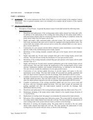
1.01 SUMMARY: This section summarizes the Work of the Project as covered in detail in the complete Contract<br />
Documents. This is a general summary and is not intended to be complete and all inclusive of the required<br />
Work items.<br />
1.<strong>02</strong> PROJECT DESCRIPTION:<br />
A. Description of Total Project:<br />
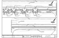
The project generally consists of the demolition and replacement of the existing dual yoke stem hoist<br />
operating systems with wire rope and drum at the S-44 Spillway Structure and G-57 Spillway<br />
Structure. Both spillway structures consist of two vertical roller gates. The S-44 Spillway Structure is<br />
located in Palm Beach County and is operated and maintained by the South Florida Water Management<br />
District (SFWMD) West Palm Beach Field Station. The site is accessible from Alternate A1A just<br />
north of Northlake Boulevard in Lake Park, Florida The G-57 Spillway Structure is located in<br />
Broward County and is operated and maintained by the SFWMD Ft. Lauderdale Field Station. The site<br />
is accessible from Atlantic Blvd, just east of Interstate 95 in Pompano Beach, Florida.<br />
The Project Scope of Work at each spillway structure shall include the following tasks:<br />
Structure S-44:<br />
• Demolish the existing yoke stem hoist operating systems at each spillway gate structure. (Total of<br />
2).<br />
• Modify the existing cast-in-place concrete piers at each spillway gate. (Total of 3). Modification<br />
shall include raising the finished elevation of the top of each pier structure by a height of 5-ft, 4-<br />
inches.<br />
• Supply and install a galvanized steel operating platform at each spillway gate structure. (Total of<br />
2).<br />
• Supply and install a wire rope and drum operating system and skid frame at each spillway gate<br />
structure. (Total of 2). These shall include all associated mechanical components including wire<br />
rope, drum operator with speed reducer, sheave blocks, coffin covers, pillow blocks, equipment<br />
guards, etc.<br />
• Modify and upgrade the existing electrical and control systems at the project site. This task will<br />
include the demolition and replacement of the existing electrical and control conduit and cabling<br />
from the existing control house to the new gate operating system platforms. This task also will<br />
include the upgrade of the existing RACU telemetry system to a Motorola ACE RTU system and<br />
Redundant Gate Operator Control Panel and ancillary equipment.<br />
• Demolish and replace the existing upstream and downstream stilling wells (Total of 2) and<br />
associated access structures and housings.<br />
• Supply and install four (4) new in-ground stilling wells. Two of the stilling wells will be located<br />
upstream of the structure and two will be located downstream of the structure. Each pairing will<br />
be installed adjacent to one another and will be installed within a common housing. The stilling<br />
wells will be equipped with either an absolute encoder connected to the Motorola ACE RTU or a<br />
Druck pressure/level transmitter connected to the Redundant Gate Operator Control Panel as<br />
shown on the Drawings.<br />
<strong>Spec</strong>. <strong>Standard</strong>: <strong>08</strong>/<strong>17</strong>/<strong>07</strong> <strong>01010</strong>-1 <strong>Revision</strong>: <strong>02</strong>/04/11
• Install new upstream and downstream staff gauges. The new staff gauges shall include two staff<br />
gauges upstream and two staff gauges downstream. Each gauge pairing will consist of one gauge<br />
set in NGVD 29 and one gauge set in NAVD 88.<br />
• Supply and install a precast concrete control building to house the new and relocated<br />
instrumentation and electrical panels. The task shall include all required sitework to facilitate<br />
placement of the building.<br />
• Relocate the existing underground liquid propane fuel storage tank for the standby generator unit.<br />
This task shall include all required site work, piping, fittings, valves, ancillary equipment and site<br />
restoration.<br />
• Replace and upgrade the existing gate position indicator sensor for each structure gate (Total of 2).<br />
• Replace and upgrade the existing electrical site service feed.<br />
• Replace and upgrade the existing site lighting systems at each spillway structure.<br />
• Replace the existing structure access ladders to meet current DISTRICT standards. (Total of 3).<br />
Structure G-57:<br />
• Demolish the existing yoke stem hoist operating systems at each spillway gate structure. (Total of<br />
2).<br />
• Supply and install a galvanized steel operating platform at each spillway gate structure. (Total of<br />
2).<br />
• Supply and install a wire rope and drum operating system and skid frame at each spillway gate<br />
structure. (Total of 2). These shall include all associated mechanical components including wire<br />
rope, drum operator with speed reducer, sheave blocks, coffin covers, pillow blocks, equipment<br />
guards, etc.<br />
• Modify and upgrade the existing electrical and control systems at the project site. This task will<br />
include the demolition and replacement of the existing electrical and control conduit and cabling<br />
from the existing control house to the new gate operating system platforms. This task also will<br />
include the upgrade of the existing RACU telemetry system to a Motorola ACE RTU system and<br />
Redundant Gate Operator Control Panel and ancillary equipment.<br />
• Supply and install four (4) new in-ground stilling wells. Two of the stilling wells will be located<br />
upstream of the structure and two will be located downstream of the structure. Each pairing will<br />
be installed adjacent to one another and will be installed within a common housing. The stilling<br />
wells will be equipped with either an absolute encoder connected to the Motorola ACE RTU or a<br />
Druck pressure/level transmitter connected to the Redundant Gate Operator Control Panel as<br />
shown on the Drawings.<br />
• Install new upstream and downstream staff gauges. The new staff gauges shall include two staff<br />
gauges upstream and two staff gauges downstream. Each gauge pairing will consist of one gauge<br />
set in NGVD 29 and one gauge set in NAVD 88.<br />
• Supply and install a precast concrete control building to house the new and relocated<br />
instrumentation and electrical panels. The task shall include all required sitework to facilitate<br />
placement of the building.<br />
• Replace and upgrade the existing gate position indicator sensor for each structure gate (Total of 2).<br />
• Replace and upgrade the existing site lighting systems at each spillway structure.<br />
<strong>Spec</strong>. <strong>Standard</strong>: <strong>08</strong>/<strong>17</strong>/<strong>07</strong> <strong>01010</strong>-2 <strong>Revision</strong>: <strong>02</strong>/04/11
• Replace the existing overhead electrical site service feed with a below grade service feed.<br />
• Replace the existing structure access ladders to meet current DISTRICT standards. (Total of 2).<br />
All onsite work tasks shall be completed within the dry season as outlined and discussed below.<br />
1.03 RELATED CONTRACT ACTIVITIES:<br />
A. There are no related contract activities associated with this project.<br />
1.04 WORK PERFORMED BY OTHERS:<br />
A. Contractor shall be responsible for performing all work associated with the project.<br />
1.05 CONTRACTOR'S USE OF PREMISES: See General Terms & Conditions Article 6.11.<br />
A. During construction activities, the CONTRACTOR shall be responsible for maintaining all access<br />
roads in good condition, including grading and drainage. See General Terms & Conditions Article<br />
6.13.<br />
B. The CONTRACTOR shall ensure that all construction equipment crossing the following DISTRICT<br />
bridges shall not exceed the maximum rating shown in the tabulation. The CONTRACTOR shall<br />
verify the actual condition of the bridge and provide signed and sealed certifications indicating that the<br />
construction equipment crossing the bridges will not adversely impact the structural integrity of the<br />
bridges. As-built drawings of the existing DISTRICT bridges may be available upon request.<br />
Structure<br />
Rating<br />
S-44 Not Determined<br />
G-57 Not Determined*<br />
*CONTRACTOR is advised that there is an existing maintenance access bridge at Structure G-57. The<br />
bridge is constructed using 15-inch precast hollowcore concrete decking. There is no available load<br />
rating for the access bridge. CONTRACTOR may, at his discretion, use the access bridge to perform<br />
portions of the work. It shall be the CONTRACTOR’S sole responsibility to repair all damages to the<br />
bridges which occur as a result of construction activities.<br />
1.06 DISTRICT'S USE OF PREMISES:<br />
A. Partial District Occupancy: The DISTRICT reserves the right to occupy and to place and install<br />
equipment in areas of the Project, prior to Substantial Completion provided that such occupancy does<br />
not interfere with completion of the Work. Such placing of equipment and partial occupancy shall not<br />
constitute acceptance of the Work.<br />
1.<strong>07</strong> WORK SEQUENCE, COORDINATION ACTIVITIES AND SCHEDULED DATES:<br />
A. General: The CONTRACTOR will coordinate its work with other adjacent contractors, landowners<br />
and DISTRICT activities, with specific attention to access and staging areas. The construction<br />
sequence shall be determined by the CONTRACTOR subject to the DISTRICT’s needs for continuous<br />
access and operation as outlined below. The CONTRACTOR may suggest modifications to the<br />
sequence provided the access and operational requirements are satisfied and compliance with the<br />
overall contract period is achieved. In general, the construction sequence has been developed to ensure<br />
that at least one spillway gate at each project site is operable at all times. The CONTRACTOR is<br />
responsible for following the steps of construction outlined in this sequence of construction in the<br />
order they are shown. Any variance from the sequence must be agreed to by the DISTRICT, in writing,<br />
prior to being undertaken by the CONTRACTOR. The sequence of construction and operational<br />
requirements are presented herein.<br />
<strong>Spec</strong>. <strong>Standard</strong>: <strong>08</strong>/<strong>17</strong>/<strong>07</strong> <strong>01010</strong>-3 <strong>Revision</strong>: <strong>02</strong>/04/11
1. Work will proceed on only one gate operator at a time. The remaining gate shall remain in service<br />
continuously.<br />
2. The CONTRACTOR should expect normal remote operation of the remaining gate 24 hours per<br />
day seven day per week. However, during different phases of construction the remaining operable<br />
gate must be either on remote operation or manual operation. If manual operation is necessary the<br />
CONTRACTOR shall provide the applicable DISTRICT Field Station staff access at all times to<br />
the structure to perform the manual operation of the gate 24 hours a day 7 days per week.<br />
3. Before the RTU replacement and change over from RACU to Motorola ACE commences, the<br />
push button local manual controls must be isolated from the RTU so that they can remain<br />
functional for local manual operation. This must be verified by the applicable DISTRICT Field<br />
Station prior to RTU replacement start.<br />
4. The local manual controls of the gates must remain active throughout the entire RTU replacement.<br />
5. The CONTRACTOR shall provide a crane, in the time frames specified in the Dry Season and<br />
Wet Season requirements that can lift the weight of the gate and the frictional force of the gate.<br />
The weight of each gate at the S-44 project site is approximately 3,670 pounds and the estimated<br />
total vertical lift force required is approximately <strong>17</strong>,200 pounds. The weight of each gate at the G-<br />
57 project site is approximately 7,000 pounds and the estimated total vertical lift force required is<br />
approximately 9,100 pounds. The CONTRACTOR is required to confirm all vertical lifting forces<br />
based on the detailed design calculations to be completed and submitted by his designated hoist<br />
supplier.<br />
6. The CONTRACTOR shall supply all rigging, tackle and slings necessary to accomplish this work.<br />
The DISTRICT will not provide these items and will take ownership of said items upon<br />
completion of the project. All rigging items provided and supplied to the DISTRICT by the<br />
CONTRACTOR shall be new and shall be selected and procured specifically for use on the<br />
project.<br />
7. The CONTRACTOR shall demonstrate that the equipment provided by the CONTRACTOR<br />
including the crane will fit onsite and raise the gate to a full open position. The CONTRACTOR<br />
shall provide the DISTRICT with 48-hours advanced notice of the proposed date which the<br />
CONTRACTOR intends to demonstrate conformance with this requirement<br />
8. Anything damaged by the CONTRACTOR during the course of this contract must be brought to<br />
the attention of the DISTRICT construction management representative as soon as possible.<br />
Damage to operational equipment (gate sensors, etc.) must be repaired immediately. Nonoperational<br />
items (fencing, etc.) must be repaired within two weeks. Repairs due to such damage<br />
will be at the CONTRACTOR’S expense.<br />
Dry Season Requirements:<br />
Dry Season Requirements: All onsite work tasks to be completed at each of the project sites shall be<br />
completed during the dry season which for the purpose of this contract commences on November 1 and<br />
ends April 30. During the dry season the CONTRACTOR shall provide a crane at the project site, to lift<br />
and secure the inoperable gate during construction within eight (8) hours or less from the time of original<br />
request by the DISTRICT. Once the crane is onsite the CONTRACTOR shall provide the required staff and<br />
equipment to raise and/or lower the gate as directed by the DISTRICT 24 hours a day 7 days a week.<br />
Once the gate has been lifted the CONTRACTOR shall be responsible to make any additional adjustments<br />
on an hourly basis or at a less frequent interval as directed by the DISTRICT. Upon gate closure the<br />
CONTRACTOR may, at his option, remove the crane from the project site. The CONTRACTOR is<br />
<strong>Spec</strong>. <strong>Standard</strong>: <strong>08</strong>/<strong>17</strong>/<strong>07</strong> <strong>01010</strong>-4 <strong>Revision</strong>: <strong>02</strong>/04/11
specifically advised however that any costs associated with mobilizing and demobilizing a crane to each<br />
project site during the course of the project, regardless of the number of events, shall be borne by the<br />
CONTRACTOR. No additional compensation will be provided by the DISTRICT.<br />
Wet Season Requirements:<br />
Wet Season Requirements: All onsite work tasks to be completed at each of the project sites shall be<br />
completed outside of the wet season which for the purpose of this contract commences on May 1 and ends<br />
October 31. All work for the project shall be substantially complete and the gates remotely operable at<br />
their design discharge, no later than April 30. If work extends past April 30 then the CONTRACTOR shall<br />
provide a crane at the project site, to lift and secure the inoperable gate during construction within four (4)<br />
hours or less from the time of original request by the DISTRICT. Once onsite the CONTRACTOR shall<br />
provide the required staff and equipment to raise and/or lower the gate, as directed by the DISTRICT,<br />
hourly 24 hours a day 7 days a week or at a less frequent interval as directed by the DISTRICT. Once the<br />
gate has been lifted the CONTRACTOR shall be responsible to make any additional adjustments requested<br />
by the DISTRICT on an hourly basis. This requirement is in addition to any other penalties, damages or<br />
requirements stipulated elsewhere in the Contract Documents. Upon gate closure the CONTRACTOR<br />
may, at his option, remove the crane from the project site. The CONTRACTOR is specifically advised<br />
however that any costs associated with mobilizing and demobilizing a crane to each project site during the<br />
course of the project, regardless of the number of events, shall be borne by the CONTRACTOR. No<br />
additional compensation will be provided by the DISTRICT.<br />
1.<strong>08</strong> COPIES OF DOCUMENTS: See General Terms & Conditions Article 2.<strong>02</strong><br />
1.09 LIST OF DRAWINGS: S-44 and G-57 Gate Operator Replacement, Palm Beach and Broward Counties,<br />
Florida; 94 Sheets.<br />
A. Reference Materials:<br />
1. The following reference materials are available for inspection at the offices of the DISTRICT.<br />
These materials are for reference only, are provided as is, are not contractual documents and do<br />
not replace the CONTRACTOR’s due diligence in the bid preparation.<br />
• Canal <strong>17</strong> and Structure 44 Record Drawings, U.S. Army Corps of Engineers, August<br />
1959<br />
• Construction Plans and <strong>Spec</strong>ifications for Reconstruction of Structure G-57 on the<br />
Pompano Canal for the South Florida Water Management District, Sheets 1, 2, 4, 5, 9, 10<br />
and 11 of 11 sheets, Gee and Jensen Engineers, Architects, Planners, <strong>Inc</strong>., 1987<br />
END OF SECTION<br />
<strong>Spec</strong>. <strong>Standard</strong>: <strong>08</strong>/<strong>17</strong>/<strong>07</strong> <strong>01010</strong>-5 <strong>Revision</strong>: <strong>02</strong>/04/11
SECTION 01015<br />
DEFINITIONS AND STANDARDS<br />
PART 1 - GENERAL<br />
1.01 SCOPE:<br />
A. Definitions:<br />
1. A substantial amount of specification language constitutes definitions for terms found in other<br />
areas of Contract Documents including drawings which must be recognized as diagrammatic in<br />
nature and not completely descriptive of requirements indicated.<br />
2. Certain terms used in the Contract Documents are defined in the General Terms & Conditions.<br />
Definitions and explanations are not necessarily either complete or exclusive but are general for<br />
the work.<br />
3. The term “DISTRICT”, as defined in the General Terms & Conditions and used in these<br />
specifications, is further defined as the District or District’s authorized representative, which<br />
may include, but is not limited to, the Design Engineer or Construction Manager.<br />
B. General Requirements: General requirements are the provisions or requirements of Division 1 sections<br />
which apply to the entire work of the Contract.<br />
1.<strong>02</strong> FORMAT AND SPECIFICATION EXPLANATIONS:<br />
A. Format Explanation: The format of principal portions of these specifications can be described as<br />
follows, although other portions may not fully comply and no particular significance will be attached<br />
to such compliance or noncompliance.<br />
1. Sections and Divisions: For convenience, basic unit of specification text is a "section", each<br />
unit of which is named and numbered. These are organized into related families of sections,<br />
and various families of sections are organized into "divisions", which are recognized as the<br />
present industry consensus on uniform organization and sequencing of specifications. The<br />
section title is not intended to limit meaning or content of section, nor to be fully descriptive of<br />
requirements specified therein, nor to be an integral part of text.<br />
2. Section Numbering: Used for identification and to facilitate cross-references in contract<br />
documents. Sections are placed in numeric sequence; however, numbering sequence is not<br />
complete, and listing of sections in Table of Contents at beginning of Contract Documents must<br />
be consulted to determine numbers and names of specification sections in these Contract<br />
Documents.<br />
3. Page Numbering: Numbered independently for each section. Section number is shown with<br />
page number at bottom of each page to facilitate location of text.<br />
4. Parts: Each section of these specifications generally has been subdivided into three (3) basic<br />
parts for uniformity and convenience (Part 1 "General", Part 2 "Products", and Part 3<br />
"Execution"). These parts do not limit the meaning of text within. Some sections may not<br />
contain all three parts when not applicable, or may contain more than three parts to add clarity<br />
to organization of section.<br />
5. Imperative Language: Used generally in specifications. Except as otherwise indicated,<br />
requirements expressed imperatively are to be performed by the CONTRACTOR. For clarity<br />
of reading, at certain locations contrasting subjective language is used to describe<br />
responsibilities which must be fulfilled indirectly by the CONTRACTOR or, when so noted, by<br />
others.<br />
6. <strong>Spec</strong>ialists, Assignments: In certain instances, specification text requires that specific work be<br />
assigned to specialists or expert entities who must be engaged for performance of those units of<br />
work. These must be recognized as special requirements over which the CONTRACTOR has<br />
<strong>Spec</strong>. <strong>Standard</strong>: 01/11/<strong>07</strong> 01015-1 <strong>Revision</strong>: 12/09/09
no choice or option. These assignments must not be confused with, and are not intended to<br />
interfere with, normal application of regulations, union jurisdictions and similar conventions.<br />
Nevertheless final responsibility for fulfillment of the entire set of requirements remains with<br />
the CONTRACTOR.<br />
7. Trades: Except as otherwise specified or indicated, the use of titles such as "carpentry" in<br />
specification text, implies neither that the work must be performed by an accredited or<br />
unionized tradesperson of corresponding generic name (such as "carpenter"), nor that specified<br />
requirements apply exclusively to work by tradespersons of that corresponding generic name.<br />
B. <strong>Spec</strong>ification Content: Because of methods by which this project specification has been produced,<br />
certain general characteristics of contents and conventions in use of language are explained as follows:<br />
1. <strong>Spec</strong>ifying Methods: The techniques or methods of specifying requirements varies throughout<br />
text, and may include "prescriptive", "compliance with standards", "performance",<br />
"proprietary", or a combination of these. The method used for specifying one unit of work has<br />
no bearing on requirements for another unit of work.<br />
2. Overlapping and Conflicting Requirements: Where compliance with two (2) or more industry<br />
standards or sets of requirements is specified, and overlapping of those different standards or<br />
requirements establishes different or conflicting minimums or levels of quality, notify the<br />
DISTRICT for a decision as specified in the General Terms & Conditions.<br />
3. Abbreviations: Throughout the Contract Documents are abbreviations implying words and<br />
meanings which will be appropriately interpreted. <strong>Spec</strong>ific abbreviations have been<br />
established, principally for lengthy technical terminology, and in conjunction with coordination<br />
of specification requirements, with notations on drawings and in schedules. These are normally<br />
defined at first instance of use. Organizational and association names and titles of general<br />
standards are also abbreviated.<br />
1.03 DRAWING SYMBOLS: Except as otherwise indicated, graphic symbols used on Drawings are those<br />
symbols recognized in the construction industry for purposes indicated. Refer instances of uncertainty to the<br />
DISTRICT for clarification.<br />
1.04 INDUSTRY STANDARDS - APPLICABILITY: Applicable standards of construction industry have the<br />
same force and effect, and are made a part of Contract Documents by reference, as if copied directly into the<br />
Contract Documents, or as if published copies were bound herewith. Referenced standards referenced<br />
directly in the Contract Documents or by governing regulations have precedence over non-referenced<br />
standards which are recognized in industry for applicability to work.<br />
END OF SECTION<br />
<strong>Spec</strong>. <strong>Standard</strong>: 01/11/<strong>07</strong> 01015-2 <strong>Revision</strong>: 12/09/09
SECTION 01<strong>02</strong>0<br />
MEASUREMENT AND PAYMENT<br />
PART 1 - GENERAL<br />
1.01 LUMP SUM CONTRACT: Unless indicated on the Contract Documents, all work indicated on the Contract<br />
Drawings and specified in the Bid Documents and Contract shall be included in the Contract Sum indicated<br />
on the Bid Form. The following is a description of the Work listed in the Bid Form and is not intended to be<br />
complete and all-inclusive of the required work items. The Work shall include all miscellaneous and ancillary<br />
items necessary to construct a complete and functional Project.<br />
A. Bid Item A. Lump Sum – Complete Project: “S-44 and G-57 Gate Operator Replacement”.<br />
The Contractor will be responsible for providing cost loading quantities as described in Section 01310,<br />
2.<strong>02</strong>A.<br />
1.<strong>02</strong> BASIS FOR PAYMENTS: The above descriptions generally outline the scope of work required for those<br />
elements of the Work to be paid for under each lump sum item listed in the Bid Form. Those lump sum<br />
amounts shall be further distributed in accordance with subvalues identified in the approved Schedule of<br />
Values specified in GENERAL TERMS & CONDITIONS, Article 2.<strong>07</strong>.<br />
A. The CONTRACTOR shall submit the initial Schedule of Values in electronic spreadsheet (Microsoft<br />
Excel) format prior to commencing work. The Schedule of Values activities shall match the Contract<br />
Schedule activities. Each activity in the Schedule of Values shall also indicate the material quantity,<br />
unit price and total price as described in SECTION 01310.<br />
B. The CONTRACTOR shall have ninety (90) business days after CONTRACT execution, to produce the<br />
required Insurance Declaration Page of Policy for the insurance requirements set forth in the General<br />
Terms & Conditions, and the Insurance Requirements Checklist. DISTRICT may refuse to make<br />
whole or part of any payment if the CONTRACTOR fails to submit the required Insurance Policy<br />
Declaration Page as stated in the CONTRACT.<br />
C. The Schedule of Values shall itemize separately all major work items as listed below:<br />
Structure S-44<br />
• Mobilization, LS<br />
• Demolition, LS<br />
• Concrete Work, LS<br />
• Galvanized Steel Operator Platform, EA<br />
• Wire Drum Hoist Unit with Cover, EA<br />
• Mechanical, LS<br />
• LP Fuel Tank Relocation, LS<br />
• Coatings, LS<br />
• Precast Concrete Control Building, EA<br />
• Gate Lifting Rigging, Tackle and Slings, LS<br />
• Sodding, SY<br />
• Stilling Wells, EA<br />
<strong>Spec</strong>. <strong>Standard</strong>: 05/09/<strong>07</strong> 01<strong>02</strong>0-1 <strong>Revision</strong>: <strong>02</strong>/04/11
• Site Electrical, LS<br />
• Electrical Service Feed Replacement and Upgrades, LS<br />
• Instrumentation and Telemetry System Upgrades, LS<br />
• Site Restoration, LS<br />
• Demobilization, LS<br />
Structure G-57<br />
• Mobilization, LS<br />
• Demolition, LS<br />
• Galvanized Steel Operator Platform, EA<br />
• Wire Drum Hoist Unit with Cover, EA<br />
• Mechanical, LS<br />
• Coatings, LS<br />
• Precast Concrete Control Building, EA<br />
• Gate Lifting Rigging, Tackle and Slings, LS<br />
• Sodding, SY<br />
• Stilling Wells, EA<br />
• Site Electrical, LS<br />
• Electrical Service Feed Replacement and Upgrades, LS<br />
• Instrumentation and Telemetry System Upgrades, LS<br />
• Site Restoration, LS<br />
• Demobilization, LS<br />
1.03 PAYMENTS: Payments shall be in accordance with the provisions of the GENERAL TERMS &<br />
CONDITIONS, Article 14.<br />
END OF SECTION<br />
<strong>Spec</strong>. <strong>Standard</strong>: 05/09/<strong>07</strong> 01<strong>02</strong>0-2 <strong>Revision</strong>: <strong>02</strong>/04/11
SECTION 01045<br />
CUTTING AND PATCHING<br />
PART 1 - GENERAL<br />
1.01 WORK INCLUDED:<br />
A. Definition: "Cutting and patching" includes cutting into existing construction to provide for the<br />
installation or performance of other work and subsequent fitting and patching required to restore<br />
surfaces to their original condition.<br />
1. Cutting and patching is performed for coordination of the work, to uncover work for access or<br />
inspection, to obtain samples for testing, to permit alterations to be performed or for other<br />
similar purposes.<br />
2. Cutting and patching performed during the manufacture of products, or during the initial<br />
fabrication, erection or installation processes is not considered to be "cutting and patching"<br />
under this definition. Drilling of holes to install fasteners and similar operations are also not<br />
considered to be "cutting and patching."<br />
B. Refer to other sections of these specifications and the Drawings for specific cutting and patching<br />
requirements and limitations applicable to individual units of work.<br />
1. Unless otherwise specified, requirements of this section apply to mechanical and electrical<br />
work.<br />
2. Refer to Division 15 and Division 16 sections for additional requirements and limitations on<br />
cutting and patching of mechanical and electrical work.<br />
1.<strong>02</strong> SUBMITTALS:<br />
A. Procedural Proposal for Cutting and Patching: Prior approval of cutting and patching is required,<br />
submit proposed procedures for this work well in advance of the time work will be performed and<br />
request approval to proceed. <strong>Inc</strong>lude the following information, as applicable, in the submittal:<br />
1. Describe nature of the work and how it is to be performed, indicating why cutting and patching<br />
cannot be avoided.<br />
2. Describe anticipated results of the work in terms of changes to existing work, including<br />
structural, operational and visual changes as well as other significant elements.<br />
3. List products to be used and firms that will perform work.<br />
4. Give dates when work is expected to be performed.<br />
5. List utilities that will be disturbed or otherwise be affected by work, including those that will be<br />
relocated and those that will be out-of-service temporarily.<br />
a. Indicate how long utility service will be disrupted.<br />
6. Where cutting and patching of structural work involves the addition of reinforcement, submit<br />
details and engineering calculations to show how that reinforcement is integrated with original<br />
structure to satisfy requirements.<br />
B. Approval by the DISTRICT to proceed with cutting and patching work does not waive the<br />
DISTRICT'S right to later require complete removal and replacement of work found to be cut and<br />
patched in an unsatisfactory manner.<br />
1.03 QUALITY ASSURANCE:<br />
A. Requirements for Structural Work: Do not cut and patch structural work in a manner that would result<br />
in a reduction of load-carrying capacity or of load-deflection ratio.<br />
<strong>Spec</strong>. <strong>Standard</strong>: 11/27/06 01045-1 <strong>Revision</strong>: 12/09/09
B. Operational and Safety Limitations: Do not cut and patch operational elements or safety related<br />
components in a manner that would result in a reduction of their capacity to perform in the manner<br />
intended, including energy performance, or that would result in increased maintenance, or decreased<br />
operational life or decreased safety.<br />
C. Visual Requirements: Do not cut and patch work exposed on the exterior or interior of any building or<br />
structure in a manner that would, in the DISTRICT'S opinion, result in lessening the building's<br />
aesthetic qualities.<br />
1. Do not cut and patch work in a manner that would result in substantial visual evidence of cut<br />
and patch work.<br />
2. Remove and replace work judged by the DISTRICT to be cut and patched in a visually<br />
unsatisfactory manner.<br />
3. Retain the original installer or fabricator if possible, or another recognized experienced and<br />
specialized firm for cutting and patching.<br />
PART 2 - PRODUCTS<br />
2.01 MATERIALS:<br />
A. General: Except as otherwise indicated, or as directed by the DISTRICT, use materials for cutting and<br />
patching that are identical to existing materials.<br />
B. If identical materials are not available or cannot be used, use materials that match existing adjacent<br />
surfaces to the fullest extent possible with regard to visual effect.<br />
C. Use materials for cutting and patching that will result in equal-or-better performance characteristics.<br />
PART 3 - EXECUTION<br />
3.01 INSPECTION:<br />
A. Before cutting, examine the surfaces to be cut and patched and the conditions under which the work is<br />
to be performed. If unsafe or otherwise unsatisfactory conditions are encountered, take corrective<br />
action before proceeding with the work.<br />
B. Coordinate layout of the work and resolve potential conflicts before proceeding with the work.<br />
3.<strong>02</strong> PREPARATION:<br />
A. Temporary Support: To prevent failure, provide temporary support of work to be cut.<br />
B. Protection: Protect other work during cutting and patching to prevent damage. Provide protection<br />
from adverse weather conditions for that part of the project that may be exposed during cutting and<br />
patching operations.<br />
1. Avoid interference with use of adjacent facilities or interruption of free passage to adjacent<br />
facilities.<br />
2. Take precautions not to cut existing pipes, conduits or ducts serving the building but scheduled<br />
to be relocated until provisions have been made to by-pass them. Coordinate with the<br />
DISTRICT.<br />
<strong>Spec</strong>. <strong>Standard</strong>: 11/27/06 01045-2 <strong>Revision</strong>: 12/09/09
3.03 PERFORMANCE:<br />
A. General: Employ skilled workmen to perform cutting and patching work. Except as otherwise<br />
indicated or as approved by the DISTRICT, proceed with cutting and patching at the earliest feasible<br />
time and complete work without delay.<br />
B. Cutting: Cut the work using methods that are least likely to damage work to be retained or adjoining<br />
work. Where possible, review proposed procedures with the original installer; comply with original<br />
installer's recommendations.<br />
1. General: Use hand or small power tools designed for sawing or grinding, not hammering and<br />
chopping, where cutting is required. Use of gasoline-powered tools will not be permitted in<br />
enclosed spaces.<br />
2. Cut through concrete and masonry using a cutting machine such as a carborundum saw or core<br />
drill to insure a neat hole.<br />
3. Cut holes and slots neatly to size required with minimum disturbance of adjacent work.<br />
4. Cut or drill from the exposed or finished side into concealed surfaces to avoid marring existing<br />
finished surfaces.<br />
5. Temporarily cover openings when not in use.<br />
C. By-pass utility services such as pipe and conduit, before cutting, where such utility services are shown<br />
or required to be removed, relocated or abandoned.<br />
D. Cut off conduit and pipe in walls or partitions to be removed. After by-pass and cutting, cap, valve or<br />
plug and seal tight remaining portion of pipe and conduit to prevent entrance of moisture or other<br />
foreign matter.<br />
E. Patching: Patch with seams which are durable and as invisible as possible. Comply with specified<br />
tolerances for the work.<br />
1. Inspect and test patched areas to demonstrate integrity of work where feasible.<br />
2. Restore exposed finishes of patched areas and where necessary extend finish restoration into<br />
retained adjoining work in a manner which will eliminate evidence of patching and refinishing.<br />
3. Patch and repair floor and wall surfaces in the new space to provide an even surface of uniform<br />
color and appearance where removal of walls or partitions extends one finished area into<br />
another finished area.<br />
4. If necessary to achieve uniform color and appearance, remove existing floor and wall coverings<br />
and replace with new materials.<br />
5. Extend final paint coat over entire unbroken surface containing patch, after patched area has<br />
received prime and base coat where patch occurs in a smooth painted surface.<br />
6. Patch, repair or re-hang existing ceilings as necessary to provide an even plane surface of<br />
uniform appearance.<br />
3.04 CLEANING:<br />
A. Thoroughly clean areas and spaces where work is performed or used as access to work. Remove<br />
completely paint, mortar, oils, putty and items of similar nature.<br />
B. Thoroughly clean piping, conduit and similar features before painting or other finishing is applied.<br />
C. Restore damaged pipe covering to its original condition.<br />
END OF SECTION<br />
<strong>Spec</strong>. <strong>Standard</strong>: 11/27/06 01045-3 <strong>Revision</strong>: 12/09/09
SECTION 01050<br />
FIELD ENGINEERING<br />
PART 1 - GENERAL (See General Terms & Conditions Article 4.05 "Reference Points.")<br />
1.01 The CONTRACTOR shall engage a licensed engineer of the discipline required, registered in the State of<br />
Florida, to perform engineering services for temporary facilities including the design of shoring systems,<br />
shores, earth and water retaining systems, forms, temporary erection supports, and similar items provided by<br />
the CONTRACTOR as part of its means and methods of construction.<br />
The CONTRACTOR shall engage a professional surveyor and mapper registered in the State of Florida to<br />
perform the necessary layout, survey control and monumentation.<br />
The CONTRACTOR shall provide one set of As-Built Drawings depicting all elevations both NAVD 88 and<br />
NGVD 29. The NGVD 29 elevation shall be italicized, bracketed, and underscored.<br />
PART 2 - CONTRACTOR CONSTRUCTION STAKING<br />
2.01 DESCRIPTION: In connection with this WORK, CONTRACTOR shall:<br />
A. Perform all construction layout and reference staking necessary for the proper control and satisfactory<br />
completion of the WORK.<br />
B. Run a level circuit between vertical control points indicated to check plan benchmarks and establish<br />
new benchmarks where necessary.<br />
2.<strong>02</strong> CONSTRUCTION REQUIREMENTS:<br />
A. The CONTRACTOR’s personnel performing the construction staking shall work under the direct<br />
supervision of a Florida registered engineer or Florida licensed land surveyor. Submit name and<br />
address of individual responsible for surveying to the DISTRICT prior to start of survey activities.<br />
B. The CONTRACTOR shall be solely and completely responsible for the accuracy of the line and grade<br />
of all features of the Work. Any errors or apparent discrepancies found in previous surveys, plans, or<br />
specifications shall be called to the attention of the DISTRICT by the CONTRACTOR for correction<br />
or interpretation prior to proceeding with the WORK.<br />
C. Field notes shall be kept in standard, bound field notebooks in a clear, orderly, and neat manner<br />
consistent with standard engineering practices.<br />
D. The CONTRACTOR shall be responsible for the placement and preservation of adequate ties and<br />
reference to all control points, whether established by him or found on the project, necessary for the<br />
accurate reestablishment of all base lines or centerlines shown on the Plans. All land ties (i.e. section<br />
corners, fractional section corners, and similar items) that may be lost or destroyed during construction<br />
shall be carefully referenced and replaced.<br />
E. The supervision of the CONTRACTOR’s construction engineering personnel shall be the<br />
responsibility of the CONTRACTOR; any deficient engineering layout or construction work which<br />
may be the result of inaccuracies in his staking operations or of his failure to report inaccuracies found<br />
in work previously done by the Design Engineer shall be corrected at the expense of the<br />
CONTRACTOR.<br />
F. Station Identification: On linear elements of construction (such as levees, canals, and similar items)<br />
the CONTRACTOR shall place temporary identifying signs at intervals no greater than 500 feet using<br />
4-foot sections of 1-inch by 4-inch lumber driven into the ground. The signs shall identify the station<br />
at that location.<br />
G. In order to expedite the commencement of construction operations, the staking operation may<br />
commence prior to the issuance of the Notice to Proceed. The CONTRACTOR shall obtain written<br />
approval of the DISTRICT prior to commencing staking.<br />
2.03 SURVEYING STANDARDS for stilling wells and water control structures:<br />
<strong>Spec</strong>. <strong>Standard</strong>: 05/03/10 01050-1 <strong>Revision</strong>: 10/4/2010
A. A permanent mark shall be established identifying the elevation measuring point on the rim of all<br />
stilling wells. A permanent noncorrosive plate or tag shall be attached to stilling wells with the<br />
measuring point elevation.<br />
1. All vertical elevations shall commence from a minimum of two National Geodetic Survey<br />
(NGS) second order or better published benchmarks.<br />
2. All elevations shall be established to NGS third order standards and certified to those standards<br />
by a Professional Surveyor and Mapper registered in the state of Florida.<br />
3. All level runs shall be double run (forward and back) or looped into two NGS second order or<br />
better published benchmarks.<br />
4. A site benchmark shall be set if one does not exist. The benchmark shall consist of a minimum<br />
of two eighty pound bags of concrete mix, a ferrous piece of material able to be located with a<br />
magnetic locator, and a survey cap (supplied by the DISTRICT) stamped with the site<br />
designation.<br />
5. All elevations shall be established in NAVD88 with the datum offset for conversion to<br />
NGVD29. Datum offsets shall be made using the DISTRICT’s vertical datum conversion<br />
application (VDCA) available on the web at http://my.sfwmd.gov/vdcaweb. The datum<br />
conversion to NGVD 29 shall be made from the closest bench mark. The NGVD 29<br />
conversions shall be accurate to 0.01 feet...<br />
6. State Plane Coordinates (NAD 83/99) shall be established at all stilling well and benchmark<br />
locations with a positional accuracy of +/- three feet.<br />
7. A DISTRICT benchmark description sheet shall be completed for each set benchmark.<br />
8. If there are no second order or better published benchmarks within six miles of the site, contact<br />
the DISTRICT Surveying Section representative at (561) 682-6688 prior to commencement.<br />
9. Contact the DISTRICT Survey Section prior to commencement to check for previously<br />
established site benchmarks that may be suitable to use.<br />
10. A listing of NGVD 29 values associated with the Comprehensive Everglades Restoration Plan<br />
(CERP) Geodetic Vertical Control Network is available from the DISTRICT.<br />
B. All structures shall have a permanent benchmark mounted as shown on the plans. The marker for the<br />
benchmark can be obtained from the DISTRICT Survey Section, (561) 682-6688. The Contractor shall<br />
only stamp or engrave the benchmark identification and not the elevation.<br />
C. The CONTRACTOR shall install two staff gauges, one permanent slide mounted staff gauge on<br />
concrete pile and set in NAVD 88, and one temporary staff gauge on timber pile and set in NGVD 29,<br />
at each location requiring a staff gauge. A 3” x 7” sign with 2” alphabet height shall be installed on top<br />
of each staff gauge to identify the NAVD 88 (white lettering on red background) or NGVD 29 (black<br />
lettering on white background) Datum.<br />
2.04 RECORDS AND SUBMITTALS:<br />
A. Submittal:<br />
1. Provide DISTRICT a copy of the designs described in Paragraph 1.01 signed and sealed by the<br />
licensed engineer.<br />
2. Provide DISTRICT the data required for the individual responsible for layout and records as<br />
required in Paragraph 2.<strong>02</strong> A.<br />
B. Records: At the end of the Project, submit to the DISTRICT a certified site survey showing<br />
coordinates and elevations of the completed Work. Submit a copy of the field notes required in<br />
Paragraph 2.<strong>02</strong>.C. These are part of the record documents required in SECTION 0<strong>17</strong>00.<br />
C. Cross-sections: Canal and Levee cross-sections shall be submitted as specified in SECTION <strong>02</strong>200.<br />
END OF SECTION<br />
<strong>Spec</strong>. <strong>Standard</strong>: 05/03/10 01050-2 <strong>Revision</strong>: 10/4/2010
SECTION 01<strong>07</strong>1<br />
STANDARD REFERENCES<br />
Wherever used in the project manual, the following abbreviations will have the meanings listed:<br />
AA<br />
Aluminum Association <strong>Inc</strong>orporated<br />
818 Connecticut Avenue, N.W.<br />
Washington, D.C. 20006<br />
AABC<br />
AAMA<br />
AASHTO<br />
ABMA<br />
ACI<br />
AEIC<br />
AFBMA<br />
AGA<br />
AGMA<br />
AHA<br />
AISC<br />
AISI<br />
Associated Air Balance Council<br />
1518 K Street N.W.<br />
Washington, D.C. 20005<br />
American Architectural Manufacturers Association<br />
2700 River Road, Suite 118<br />
Des Plaines, IL 60018<br />
American Association of State Highway and Transportation Officials<br />
444 North Capitol Street, N.W., Suite 225<br />
Washington, D.C. 20001<br />
American Bearing Manufacturers Association<br />
1101 Connecticut Avenue, N.W. Suite 700<br />
Washington, D.C. 20036<br />
American Concrete Institute<br />
P. O. Box 19150<br />
Detroit, MI<br />
Association of Edison Illuminating Companies<br />
51 East 42nd Street<br />
New York, NY 100<strong>17</strong><br />
Anti-Friction Bearing Manufacturers Association<br />
American Gas Association<br />
8501 East Pleasant Valley Road<br />
Cleveland, OH 44131<br />
American Gear Manufacturer's Association<br />
1330 Massachusetts Avenue, N.W.<br />
Washington, D.C.<br />
American Hardboard Association<br />
520 N. Hicks Road<br />
Palatine, IL 60067<br />
American Institute of Steel Construction<br />
101 Park Avenue<br />
New York, NY 100<strong>17</strong><br />
American Iron and Steel Institute<br />
1000 16th Street, N.W.<br />
Washington, D.C. 20036<br />
<strong>Spec</strong>. <strong>Standard</strong>: 04/09/06 01<strong>07</strong>1-1 <strong>Revision</strong>: 12/09/09
AITC<br />
ALSC<br />
AMCA<br />
ANSI<br />
APA<br />
API<br />
ARI<br />
ASCE<br />
ASCII<br />
ASE<br />
ASHRAE<br />
ASME<br />
ASTM<br />
American Institute of Timber Construction<br />
333 West Hampden Avenue<br />
Englewood, CO 80110<br />
American Lumber <strong>Standard</strong>s Committee<br />
P. O. Box 210<br />
Germantown, MD 2<strong>08</strong>74<br />
Air Movement and Control Association, <strong>Inc</strong>.<br />
30 West University Drive<br />
Arlington Heights, IL 60004<br />
American National <strong>Standard</strong>s Institute, <strong>Inc</strong>.<br />
1430 Broadway<br />
New York NY 10018<br />
American Plywood Association<br />
1119 A Street<br />
Tacoma, WA 98401<br />
American Petroleum Institute<br />
1801 K Street N.W.<br />
Washington, D.C. 20006<br />
Air-Conditioning and Refrigeration Institute<br />
1814 North Fort Myer Drive<br />
Arlington, VA 22209<br />
American Society of Civil Engineers<br />
345 East 47th Street<br />
New York, NY 100<strong>17</strong><br />
American <strong>Standard</strong> Code for Information Interchange<br />
United States of America <strong>Standard</strong>s Institute<br />
10 East 40th Street<br />
New York, NY 10016<br />
American <strong>Standard</strong> Safety Code for Elevators,<br />
Code Dumbwaiter and Escalators<br />
American National <strong>Standard</strong>s Institute<br />
1430 Broadway<br />
New York, NY 10018<br />
American Society of Heating, Refrigeration and Air Conditioning Engineers<br />
United Engineering Center<br />
345 East 47th Street<br />
New York, NY 100<strong>17</strong><br />
American Society of Mechanical Engineers<br />
345 East 47th Street<br />
New York, NY 100<strong>17</strong><br />
American Society for Testing and Materials<br />
1916 Race Street<br />
Philadelphia, PA 19103<br />
<strong>Spec</strong>. <strong>Standard</strong>: 04/09/06 01<strong>07</strong>1-2 <strong>Revision</strong>: 12/09/09
AWPA<br />
AWPB<br />
AWPI<br />
AWI<br />
AWS<br />
AWWA<br />
BHMA<br />
BOCA<br />
CBM<br />
CMAA<br />
CRSI<br />
CSA<br />
DEMA<br />
American Wood Preservers Association<br />
1625 Eye Street<br />
Washington, D.C. 20006<br />
American Wood Preservers Bureau<br />
7962 Conell Court<br />
P. O. Box 5283<br />
Lorton, VA 22<strong>07</strong>9<br />
American Wood Preservers Institute<br />
2750 Prosperity Avenue, Suite 550<br />
Fairfax, VA 22031-4312<br />
Architectural Woodwork Institute<br />
1952 Isaac Newton Square West<br />
Reston, VA 20190<br />
American Welding Society<br />
2501 N.W. 7th Street<br />
Miami, FL 33125<br />
American Water Works Association<br />
6666 West Quincy Avenue<br />
Denver, CO 8<strong>02</strong>35<br />
Builders Hardware Manufacturers Association<br />
355 Lexington Avenue, <strong>17</strong> th Floor<br />
New York, NY 100<strong>17</strong><br />
Building Officials and Code Administrators<br />
<strong>17</strong>926 Halstead<br />
Homewood, IL 60430<br />
Certified Ballast Manufacturers<br />
2120 Keith Building<br />
Cleveland, OH 44115<br />
Crane Manufacturers Association of America, <strong>Inc</strong>.<br />
(Formerly called: Overhead Electrical Crane Institute) (OECI)<br />
1326 Freeport Road<br />
Pittsburgh, PA 15238<br />
Concrete Reinforcing Steel Institute<br />
180 North La Salle Street<br />
Chicago, IL 60601<br />
Canadian <strong>Standard</strong>s Association<br />
<strong>17</strong>8 Rexdale Boulevard<br />
Rexdale, Ontario, M9W IR3, Canada<br />
Diesel Engine Manufacturer's Association<br />
122 East 42nd Street<br />
New York, NY 100<strong>17</strong><br />
<strong>Spec</strong>. <strong>Standard</strong>: 04/09/06 01<strong>07</strong>1-3 <strong>Revision</strong>: 12/09/09
DHI<br />
DIS<br />
EEI<br />
EIA<br />
EJMA<br />
EPA<br />
Door Hardware Institute<br />
7711 Old Springhouse Road<br />
McLean, VA 221<strong>02</strong><br />
Division of Industrial Safety<br />
California Department of Industrial Relations<br />
2422 Arden Way<br />
Sacramento, CA 95825<br />
Edison Electric Institute<br />
90 Park Avenue<br />
New York, NY 10016<br />
Electronic Industries Association<br />
2001 Eye Street, N.W.<br />
Washington, D.C. 20006<br />
Expansion Joint Manufacturer's Association<br />
25 North Broadway<br />
Tarrytown, NY 10591<br />
Environmental Protection Agency<br />
Region 4<br />
Sam Nunn Atlanta Federal Center<br />
61 Forsyth Street, SW<br />
Atlanta, GA 30303-3104<br />
ESO Electrical Safety Order, California Administrative Code, Title 8, Chap. 4, Subarticle 5<br />
Office of Procurement, Publications Section<br />
P. O. Box 20191<br />
8141 Elder Creek Road<br />
Sacramento, CA 95820<br />
FAC<br />
FEDSPEC<br />
FEDSTDS<br />
FM<br />
GANA<br />
HEI<br />
Florida Administrative Code<br />
Federal <strong>Spec</strong>ifications<br />
General Services Administration <strong>Spec</strong>ification and Consumer Information<br />
Distribution Branch<br />
Washington Navy Yard, Bldg. 197<br />
Washington, D.C. 204<strong>07</strong><br />
Federal <strong>Standard</strong>s (see FEDSPECS)<br />
Factory Mutual Research<br />
1151 Boston-Providence Turnpike<br />
Norwood, MA <strong>02</strong>062<br />
Glass Association of North America<br />
2301 Tower Road<br />
Austin, TX 78703<br />
Heat Exchange Institute<br />
122 East 42nd Street<br />
New York, NY 100<strong>17</strong><br />
<strong>Spec</strong>. <strong>Standard</strong>: 04/09/06 01<strong>07</strong>1-4 <strong>Revision</strong>: 12/09/09
HI<br />
HPMA<br />
IAPMO<br />
ICBO<br />
ICEA<br />
ICRI<br />
IEEE<br />
IES<br />
ISA<br />
ISO<br />
JIC<br />
MFMA<br />
MILSPEC<br />
Hydraulic Institute<br />
1230 Keith Building<br />
Cleveland, OH 44115<br />
Hardwood Plywood Manufacturers Association<br />
1825 Michael Faraday Drive<br />
P. O. Box 2789<br />
Reston, VA 22090-2789<br />
International Association of Plumbing and Mechanical Officials<br />
5032 Alhambra Avenue<br />
Los Angeles, CA 90032<br />
International Conference of Building Officials<br />
5360 South Workman Mill Road<br />
Whittier, CA 90601<br />
Insulated Cable Engineers Association<br />
P. O. Box P<br />
South Yarmouth, MA <strong>02</strong>664<br />
International Concrete Repair Institute<br />
3166 S. River Road, Suite 132<br />
Des Plaines, IL 60018<br />
Institute of Electrical and Electronics Engineers, <strong>Inc</strong>.<br />
345 East 47th Street<br />
New York, NY 100<strong>17</strong><br />
Illuminating Engineering Society<br />
c/o United Engineering Center<br />
345 East 47th Street<br />
New York, NY 100<strong>17</strong><br />
Instrument Society of America<br />
400 Stanwix Street<br />
Pittsburgh, PA 15222<br />
International Organization for <strong>Standard</strong>ization<br />
1, ru de Varembé,<br />
Case postale 56<br />
CH-1211 Genna 20,<br />
Switzerland<br />
Joint Industrial Council<br />
7901 Westpark Drive<br />
McLean, VA 22101<br />
Metal Framing Manufacturers Association<br />
111 E. Wacker Drive<br />
Chicago, IL 60601<br />
Military <strong>Spec</strong>ifications<br />
Naval Publications and Forms Center<br />
5801 Tabor Avenue<br />
Philadelphia, PA 19120<br />
<strong>Spec</strong>. <strong>Standard</strong>: 04/09/06 01<strong>07</strong>1-5 <strong>Revision</strong>: 12/09/09
MSS<br />
NAAMM<br />
NACE<br />
NEC<br />
NECA<br />
NELMA<br />
NEMA<br />
NESC<br />
NETA<br />
NFP<br />
NFPA<br />
NHLA<br />
NIST<br />
Manufacturers <strong>Standard</strong>ization Society of the Valve and Fittings Industry, <strong>Inc</strong>.<br />
127 Park Avenue, N.E.<br />
Vienna, VA 22180<br />
National Association of Architectural Metal Manufacturers<br />
100 South Marion Street<br />
Oak Park, IL 603<strong>02</strong><br />
National Association of Corrosion Engineers<br />
P. O. Box 986<br />
Katy, TX 77450<br />
National Electrical Code<br />
National Fire Protection Association<br />
470 Atlantic Avenue<br />
Boston, MA <strong>02</strong>210<br />
National Electrical Contractors Association<br />
3 Bethesda Metro Center, Suite 1100<br />
Bethesda, MD 2<strong>08</strong>14<br />
Northeastern Lumber Manufacturers Association, <strong>Inc</strong>.<br />
272 Turtle Road<br />
P. O. Box 87A<br />
Cumberland Center, ME 04<strong>02</strong>1<br />
National Electrical Manufacturer's Association<br />
155 East 44th Street<br />
New York, NY 100<strong>17</strong><br />
National Electric Safety Code<br />
American National <strong>Standard</strong>s Institute<br />
1430 Broadway<br />
New York, NY 10018<br />
InterNational Electrical Testing Association<br />
P. O. Box 687<br />
Morrison, CO 80465<br />
National Forest Products Association (Formerly National Lumber<br />
Manufacturer's Association)<br />
1619 Massachusetts Avenue<br />
Washington, DC 20036<br />
National Fire Protection Association<br />
Batterymarch Park<br />
Quincy, MA <strong>02</strong>269<br />
National Hardwood Lumber Association<br />
P. O. Box 34518<br />
Memphis, TN 38184-0518<br />
National Institute of <strong>Standard</strong>s and Technology<br />
100 Bureau Drive, Suite 1<strong>07</strong>0<br />
Gaithersburg, MD 2<strong>08</strong>99-1<strong>07</strong>0<br />
<strong>Spec</strong>. <strong>Standard</strong>: 04/09/06 01<strong>07</strong>1-6 <strong>Revision</strong>: 12/09/09
NSF<br />
OSHA<br />
PCI<br />
PPIC<br />
RIS<br />
RLM<br />
RMA<br />
SAE<br />
SAMA<br />
SBC<br />
SMC<br />
SBCCI<br />
SCMA<br />
National Sanitation Foundation<br />
3475 Plymouth Road<br />
P. O. Box 1468<br />
Ann Arbor, MI 48106<br />
Occupational Safety and Health Act<br />
U.S. Department of Labor<br />
Occupational and Health Administration<br />
San Francisco Regional Office<br />
450 Golden Gate Avenue, Box 360<strong>17</strong><br />
San Francisco, CA 941<strong>02</strong><br />
Prestressed Concrete Institute<br />
<strong>17</strong>5 W. Jackson Blvd., Suite 1859<br />
Chicago, IL 60604<br />
The Plumbing & Piping Industry Council, <strong>Inc</strong>.<br />
510 Shatto Place, Suite 4<strong>02</strong><br />
Los Angeles, CA 90<strong>02</strong>0<br />
Redwood Inspection Service<br />
California Redwood Association<br />
405 Enfrente Dr., Suite 200<br />
Novato, CA 94949<br />
Reflector and Lamp Manufacturers <strong>Standard</strong> Institute<br />
Rubber Manufacturers Association<br />
1400 K Street<br />
Washington, D.C. 20005<br />
Society of Automotive Engineers<br />
2 Pennsylvania Plaza<br />
New York, NY 10001<br />
Scientific Apparatus Makers Association<br />
One Thomas Circle<br />
Washington, D.C. 20005<br />
<strong>Standard</strong> Building Code<br />
Published by SBCCI<br />
<strong>Standard</strong> Mechanical Code<br />
Published by SBCCI<br />
Southern Building Code Congress International<br />
1116 Brown-Marx Building<br />
Birmingham, AL 35203<br />
Southern Cypress Manufacturers Association<br />
805 Sterick Bldg.<br />
Memphis, TN 38103<br />
<strong>Spec</strong>. <strong>Standard</strong>: 04/09/06 01<strong>07</strong>1-7 <strong>Revision</strong>: 12/09/09
SDI<br />
SMACNA<br />
SPC<br />
SPI<br />
SPIB<br />
SSPC<br />
SSPWC<br />
TEMA<br />
UL<br />
USBR<br />
USCOE<br />
WCLIB<br />
Steel Door Institute<br />
712 Lakewood Center N.<br />
14600 Detroit Avenue<br />
Cleveland, OH 441<strong>07</strong><br />
Sheet Metal and Air Conditioning Contractors<br />
National Association, <strong>Inc</strong>.<br />
8224 Old Courthouse Road<br />
Tysons Corner Vienna, VA 22180<br />
Society for Protective Coatings<br />
40 24 th Street, 6 th Floor<br />
Pittsburgh, PA 15222<br />
Society of the Plastics Industry, <strong>Inc</strong>.<br />
1275 K Street NW, Suite 400<br />
Washington, D.C. 20005<br />
Southern Pine Inspection Bureau<br />
4709 Scenic Highway<br />
Pensacola, Fl 32504<br />
Steel Structures Painting Council<br />
4400 Fifth Avenue<br />
Pittsburgh, PA 15213<br />
<strong>Standard</strong> <strong>Spec</strong>ifications for Public Works Construction<br />
Building News, <strong>Inc</strong>.<br />
3055 Overland Avenue<br />
Los Angeles, CA 90034<br />
Tubular Exchanger Manufacturer's Association<br />
331 Madison Avenue<br />
New York, NY 100<strong>17</strong><br />
Underwriters Laboratories <strong>Inc</strong>.<br />
2<strong>07</strong> East Ohio Street<br />
Chicago, IL 60611<br />
Bureau of Reclamation<br />
U.S. Department of Interior<br />
Engineering and Research Center<br />
Denver Federal Center, Building 67<br />
Denver, CO 8<strong>02</strong>25<br />
United States Corps of Army Engineers<br />
Jacksonville District<br />
P. O. Box 4970<br />
Jacksonville, FL 32232-0019<br />
West Coast Lumber Inspection Bureau<br />
6980 SW Varns Street<br />
P. O. Box 23145<br />
Portland, OR 97223<br />
<strong>Spec</strong>. <strong>Standard</strong>: 04/09/06 01<strong>07</strong>1-8 <strong>Revision</strong>: 12/09/09
WWPA<br />
Western Wood Products Association<br />
(Formerly called: West Coast Lumbermen's Association (WCLA))<br />
Yeon Building<br />
Portland, OR 97204<br />
END OF SECTION<br />
<strong>Spec</strong>. <strong>Standard</strong>: 04/09/06 01<strong>07</strong>1-9 <strong>Revision</strong>: 12/09/09
SECTION 01200<br />
PROJECT MEETINGS AND REPORTS<br />
PART 1 - GENERAL<br />
1.01 SUMMARY: This Section includes the following administrative and procedural requirements:<br />
A. Project Meetings:<br />
1. Preconstruction conference<br />
2. Progress meetings<br />
B. Schedules and Reports:<br />
1. Initial coordination submittals<br />
2. Construction progress schedule (See SECTION 01310 Construction Schedules)<br />
3. <strong>Spec</strong>ial reports<br />
1.<strong>02</strong> PROJECT MEETINGS:<br />
A. Pre-construction Conference<br />
1. The DISTRICT will administer a meeting within 10 days after the Effective Date of the<br />
Agreement, to review items stated in the following agenda and to establish a working<br />
understanding between the parties as to their relationships during conduct of the Work.<br />
2. Preconstruction conference shall be attended by:<br />
a. CONTRACTOR and his superintendent<br />
b. Representatives of principal Subcontractors and Suppliers<br />
c. Engineer and his Resident Project Representative if any<br />
d. DISTRICT or his representative<br />
e. Other affected parties determined by the DISTRICT<br />
3. Agenda:<br />
a. Projected construction schedules<br />
b. Critical Work sequencing<br />
c. Designation of responsible personnel<br />
d. Project coordination<br />
e. Procedures and Processing of:<br />
i. Field decisions<br />
ii. Substitutions<br />
iii. Submittals<br />
iv. Change Orders<br />
v. Applications for payment<br />
f. Procedures for testing<br />
g. Procedures for maintaining record documents<br />
h. Use of Premises:<br />
i. Office, work and storage and staging areas<br />
<strong>Spec</strong>. <strong>Standard</strong>: 11/27/06 01200-1 <strong>Revision</strong>: 12/09/09
ii. DISTRICT'S requirements<br />
i. Construction facilities, controls, and construction aids<br />
j. Temporary utilities<br />
k. Safety and first aid<br />
l. Security<br />
m. Requirements of any permits obtained by the DISTRICT<br />
4. Location of Meeting: The Preconstruction meeting will be held at the DISTRICT offices<br />
located at 2301 Centre Park Drive, Suite 150, West Palm Beach, FL 33409.<br />
B. Progress Meetings:<br />
1. The DISTRICT will administer a meeting a minimum of twice each month (every two weeks)<br />
and at other times requested by the DISTRICT. CONTRACTOR, Engineer and all<br />
Subcontractors active on the site shall be represented at each meeting. CONTRACTOR may<br />
request attendance by representatives of his Suppliers and other Subcontractors, or other entities<br />
concerned with current program or involved with planning, coordination or performance of<br />
future activities. All participants in the meeting shall be familiar with the Project and be<br />
authorized to conclude matters relating to the Work. CONTRACTOR is specifically advised<br />
that separate progress meetings will be required to assess and discuss the work progress at each<br />
project site. The meetings may, at the DISTRICT’S discretion, take place on the same day or<br />
on subsequent days. Each progress meeting shall be completed at the respective project site.<br />
2. CONTRACTOR and each Subcontractor shall be prepared to discuss the current construction<br />
progress report, any anticipated future changes to the schedule, and advise if their current<br />
progress or future anticipated schedules are compatible with the Work.<br />
3. If one Subcontractor is delaying another, CONTRACTOR shall direct such changes as are<br />
necessary for those involved to mutually agree on schedule changes in the best interest of<br />
construction progress.<br />
4. Agenda<br />
a. Review of construction progress since previous meeting<br />
b. Field observations, interface requirements, conflicts<br />
c. Problems which impede construction schedule<br />
d. Off-site fabrication<br />
e. Delivery schedules<br />
f. Submittal schedules and status<br />
g. Site utilization<br />
h. Temporary facilities and services<br />
i. Hours of Work<br />
j. Hazards and risks<br />
k. Housekeeping<br />
l. Quality and Work standards<br />
m. Change orders<br />
n. Documentation of information for payment request<br />
o. Corrective measures and procedures to regain projected schedule if necessary<br />
p. <strong>Revision</strong>s to construction schedule<br />
<strong>Spec</strong>. <strong>Standard</strong>: 11/27/06 01200-2 <strong>Revision</strong>: 12/09/09
q. Progress and schedule during succeeding Work period<br />
r. Review proposed changes for:<br />
i. Effect on construction schedule and on completion date<br />
ii. Effect on other contracts of the Project<br />
s. Other business<br />
5. Location of Meetings: “At the respective project sites” as previously indicated.<br />
6. Reporting: After each meeting, minutes of the meeting will be distributed to each party present<br />
and to parties who should have been present.<br />
C. <strong>Spec</strong>ial Reports:<br />
1. When an event of an unusual and significant nature occurs at the site, a special report shall be<br />
prepared and submitted. List the chain of events, persons participating, response by<br />
CONTRACTOR'S personnel, an evaluation of the results or effects, and similar pertinent<br />
information. Advise the DISTRICT in advance when such events are known or predictable.<br />
END OF SECTION<br />
<strong>Spec</strong>. <strong>Standard</strong>: 11/27/06 01200-3 <strong>Revision</strong>: 12/09/09
SECTION 01300<br />
SUBMITTALS<br />
PART 1 - GENERAL<br />
1.01 SUMMARY:<br />
A. This Section includes definitions, descriptions, transmittal, and review of "Compliance" and<br />
"Miscellaneous" Submittals.<br />
1.<strong>02</strong> GENERAL INFORMATION:<br />
A. Definitions:<br />
1. Compliance Submittals include shop drawings, product data, and samples which are prepared<br />
by the CONTRACTOR, Subcontractor, manufacturer, or Supplier and submitted by the<br />
CONTRACTOR to the DISTRICT as a basis for approval of the use of Equipment and<br />
Materials proposed for incorporation in the Work or needed to describe installation, operation,<br />
maintenance, or technical properties.<br />
a. Shop drawings include custom-prepared data of all types including drawings, diagrams,<br />
performance curves, material schedules, templates, instructions, and similar information<br />
not in standard printed form applicable to other projects.<br />
b. Product data includes standard printed information on materials, products and systems<br />
not custom-prepared for this Project, other than the designation of selections from<br />
available choices.<br />
c. Samples include both fabricated and unfabricated physical examples of materials,<br />
products, and Work; both as complete units and as smaller portions of units of Work;<br />
either for limited visual inspection or (where indicated) for more detailed testing and<br />
analysis. Mock-ups are a special form of samples which are too large to be handled in<br />
the specified manner for transmittal of sample Submittals.<br />
2. Miscellaneous Submittals are those technical reports, administrative Submittals, certificates,<br />
and guarantees not defined as shop drawings, product data, or samples.<br />
a. Technical reports include laboratory reports, tests, technical procedures, technical<br />
records, CONTRACTOR'S design analysis and CONTRACTOR'S survey field notes for<br />
construction staking, before cross-sections and after cross-sections.<br />
b. Administrative Submittals are those nontechnical Submittals required by the Contract<br />
Documents or deemed necessary for administrative records. These Submittals include<br />
maintenance agreements, workmanship bonds, Project photographs, physical work<br />
records, statements of applicability, copies of industry standards, as-constructed data,<br />
security/protection/safety data, and similar type Submittals.<br />
c. Certificates and guarantees are those Submittals on Equipment and Materials where a<br />
written certificate or guarantee from the manufacturer or Supplier is called for in the<br />
<strong>Spec</strong>ifications.<br />
d. Reports as required by Contract describing CONTRACTOR'S means and methods for<br />
items such as dewatering, earth and water retaining, erosion/turbidity control, and safety<br />
plans.<br />
3. Refer to ARTICLE 1.03 of this Part for detailed lists of documents and specific requirements.<br />
<strong>Spec</strong>. <strong>Standard</strong>: 03/30/<strong>07</strong> 01300-1 <strong>Revision</strong>: 4/20/10
B. Quality Requirements:<br />
1. Submittals such as shop drawings and product data shall be of the quality for legibility and<br />
reproduction purposes. Every line, character, and letter shall be clearly legible. Drawings such<br />
as reproducibles shall be useable for further reproduction to yield legible hard copy.<br />
2. Documents submitted to the DISTRICT that do not conform to these requirements shall be<br />
subject to rejection by the DISTRICT, and upon request by DISTRICT, CONTRACTOR shall<br />
resubmit conforming documents. If conforming Submittals cannot be obtained, such<br />
documents shall be retraced, redrawn, or photographically restored as may be necessary to meet<br />
such requirements. CONTRACTOR'S (or his Subcontractor's) failure to initially satisfy the<br />
legibility quality requirements will not relieve CONTRACTOR (or his Subcontractors) from<br />
meeting the required schedule for Submittal of shop drawings and product data.<br />
C. Language and Dimensions:<br />
1. All words and dimensional units shall be in the English language.<br />
2. Metric dimensional unit equivalents may be stated in addition to the English units.<br />
D. Submittal Completeness:<br />
1. Submittals shall be complete with respect to dimensions, design criteria, materials of<br />
construction, and other information specified to enable the DISTRICT to review the<br />
information effectively.<br />
2. Where standard drawings are furnished which cover a number of variations of the general class<br />
of equipment, each such drawing shall be individually annotated to describe exactly which parts<br />
of the drawing apply to the equipment being furnished. Use hatch marks to indicate variations<br />
that do not apply to the Submittal. The use of "highlighting markers" is not an acceptable<br />
means of annotating Submittals. Such annotation shall also include proper identification of the<br />
Submittal permanently attached to the drawing.<br />
3. Reproduction or copies of Contract Drawings or portions thereof will not be accepted as<br />
complete fabrication or erection drawings. The Contractor may use a reproduction of the<br />
DISTRICT-prepared Contract Drawings for erection drawings such as to indicate information<br />
on erection or to identify detail drawing references. Where the drawings are revised to show<br />
this additional CONTRACTOR information, the DISTRICT'S title block shall be replaced with<br />
a CONTRACTOR'S title block and the DISTRICT'S professional seal shall be removed from<br />
the drawing. The CONTRACTOR shall revise these erection drawings for subsequent<br />
DISTRICT revisions to the Contract Drawings.<br />
1.03 COMPLIANCE SUBMITTALS:<br />
A. Items shall include, but not be limited to, the following:<br />
1. Manufacturer's specifications<br />
2. Catalogs, or parts thereof, of manufactured equipment<br />
3. Shop fabrication and erection drawings<br />
4. General outline drawings of equipment showing overall dimensions, location of major<br />
components, weights, and location of required building openings and floor plates<br />
5. Detailed equipment installation drawings, showing foundation details, anchor bolt sizes and<br />
locations, baseplate sizes, location of DISTRICT'S connections, and all clearances required for<br />
erection, operation, and disassembly for maintenance.<br />
6. Schematic diagrams for electrical items, showing external connections, terminal block numbers,<br />
internal wiring diagrams, and one-line diagrams<br />
<strong>Spec</strong>. <strong>Standard</strong>: 03/30/<strong>07</strong> 01300-2 <strong>Revision</strong>: 4/20/10
7. Bills of material and spare parts list<br />
8. Instruction books and operating manuals<br />
9. Material lists or schedules<br />
10. Performance tests on equipment by manufacturers<br />
11. Concrete mix design information<br />
12. Samples and color charts<br />
13. All drawings, catalogs or parts thereof, manufacturer's specifications and data, samples,<br />
instructions, and other information specified or necessary:<br />
a. For DISTRICT to determine that the Equipment and Materials conform with the design<br />
concept and comply with the intent of the Contract Documents.<br />
b. For the proper erection, installation, operation and maintenance of the Equipment and<br />
Materials which the DISTRICT will review for general content but not for substance.<br />
c. For the DISTRICT to determine what supports, anchorages, structural details,<br />
connections, and services are required for the Equipment and Materials, and the effects<br />
on contiguous or related structures and Equipment and Materials.<br />
14. A detailed lifting plan shall be provided for each of the following tasks:<br />
a. Demolition of the existing yoke stem operator units and operator platforms at Structure<br />
S-44. (Total of 2)<br />
b. Demolition of the existing yoke stem operator units and operator platforms at Structure<br />
G-57. (Total of 2)<br />
c. Installation of the new galvanized steel platforms at Structure S-44. (Total of 2)<br />
d. Installation of the new galvanized steel platforms at Structure G-57. (Total of 2)<br />
e. Installation of the new wire drum hoist unit with frame at structure S-44. (Total of 2)<br />
f. Installation of the new wire drum hoist unit with frame at structure G-57. (Total of 2)<br />
g. Installation of the precast concrete control building at Structure S-44.<br />
h. Installation of the precast concrete control building at Structure G-57.<br />
The lifting plan shall be site specific and clearly indicate, at a minimum, the following<br />
information: crane staging area, estimated total load of lift, proposed lifting points, rigging type,<br />
rated lift capacity of rigging and rigging orientation. CONTRACTOR is specifically advised<br />
that the lifting plans specified above shall be provided to the DISTRICT for informational<br />
purposes only. CONTRACTOR is responsible for all construction means and methods and<br />
therefore assumes all liability and risks associated with all construction tasks. Lifting plans shall<br />
be submitted a minimum of 10 days in advance of scheduled lift date.<br />
B. Schedule and Log of Compliance Submittals:<br />
1. Prepare for the DISTRICT, a schedule and log for submission of all Compliance Submittals<br />
specified or necessary for DISTRICT'S review of the use of Equipment and Materials proposed<br />
for incorporation in the Work or needed for proper installation, operation or maintenance.<br />
Submit the schedule and log with the procurement schedule and Work progress schedule.<br />
Schedule submission of all Compliance Submittals to permit review, fabrication, and delivery in<br />
time so as to not cause a delay in the Work of CONTRACTOR or his Subcontractors or any<br />
other contractors as described herein.<br />
2. In establishing schedule for Compliance Submittals, allow 15 working days in DISTRICT'S<br />
office for reviewing original Submittals and 10 working days for reviewing resubmittals.<br />
<strong>Spec</strong>. <strong>Standard</strong>: 03/30/<strong>07</strong> 01300-3 <strong>Revision</strong>: 4/20/10
3. The schedule shall indicate the anticipated dates of original submission, and shall be based upon<br />
at least one resubmission of each item.<br />
4. Schedule all Compliance Submittals required prior to fabrication or manufacture for submission<br />
within 60 days of the Notice to Proceed. Schedule Compliance Submittals pertaining to storage,<br />
installation and operation at the site for DISTRICT'S acceptance prior to delivery of the<br />
Equipment and Materials.<br />
5. Resubmit Compliance Submittals the number of times required for DISTRICT'S "Submittal<br />
Accepted." However, any need for resubmittals in excess of the number set forth in the<br />
accepted schedule, or any other delay in obtaining acceptance of Submittals, will not be<br />
grounds for extension of the Contract Time, provided the DISTRICT completes its reviews<br />
within the times stated above.<br />
C. Transmittal of Compliance Submittals:<br />
1. All Compliance Submittals of Equipment and Materials furnished by Subcontractors,<br />
Manufacturers, and Suppliers shall be submitted to the DISTRICT by CONTRACTOR.<br />
2. After checking and verifying all field measurements, transmit all Compliance Submittals to the<br />
DISTRICT for acceptance as follows:<br />
a. Identify each Compliance Submittal by Submittal Number, Project name and number,<br />
Contract title and number, and the <strong>Spec</strong>ification Section and article number marked<br />
thereon or in the letter of transmittal. Unidentifiable Submittals will be returned for<br />
proper identification.<br />
b. Check and stamp Compliance Submittals of Subcontractors, Suppliers, and<br />
Manufacturers with CONTRACTOR'S approval prior to transmitting them to the<br />
DISTRICT. CONTRACTOR'S stamp of approval shall constitute a representation to the<br />
DISTRICT that CONTRACTOR has either determined and verified all quantities,<br />
dimensions, field construction criteria, materials, catalog numbers, and similar data, or he<br />
assumes full responsibility for doing so, and that he has coordinated each Compliance<br />
Submittal with the requirements of the Work and the Contract Documents.<br />
c. At the time of each submission, call to the attention of DISTRICT in the letter of<br />
transmittal any deviations from the requirements of the Contract Documents.<br />
d. Make all modifications noted or indicated by DISTRICT and return revised prints,<br />
copies, or samples until accepted. Direct specific attention in writing, or on revised<br />
Submittals, to changes other than the modifications called for by the DISTRICT on<br />
previous Submittals. After Submittals have been accepted, submit copies thereof for final<br />
distribution. Prints of accepted drawings transmitted for final distribution will not be<br />
further reviewed and are not to be revised. If errors are discovered during manufacture or<br />
fabrication, correct the Submittal and resubmit for review.<br />
e. Following completion of the Work and prior to final payment, furnish those Drawings<br />
necessary to indicate "as constructed" conditions, including field modifications, in the<br />
number of copies specified. Furnish additional copies for insertion in equipment<br />
instruction books as required. All such copies shall be clearly marked "AS<br />
CONSTRUCTED."<br />
f. Work requiring a Compliance Submittal shall not be commenced or shipped until the<br />
Submittal has been stamped "Submittal Accepted" or "Submittal Accepted as Noted" by<br />
the DISTRICT.<br />
g. Keep a copy or sample of each Compliance Submittal in good order at the site.<br />
3. Quantity Requirements:<br />
a. Except as otherwise specified, transmit all manufacturer's or fabricator's Shop Drawings<br />
in the quantity as follows:<br />
<strong>Spec</strong>. <strong>Standard</strong>: 03/30/<strong>07</strong> 01300-4 <strong>Revision</strong>: 4/20/10
i. Initial Submittal: Seven copies including one reproducible to DISTRICT. Two<br />
copies will be returned to CONTRACTOR.<br />
ii. Resubmittals: Seven copies including one reproducible to DISTRICT. Two<br />
copies will be returned to CONTRACTOR.<br />
iii. Submittal for Final Distribution: Four copies to DISTRICT.<br />
iv. As-Constructed Prints: Three copies including one reproducible to DISTRICT.<br />
b. Transmit Submittals of product data as follows:<br />
i. Initial Submittal: Seven copies to DISTRICT. Two copies will be returned to<br />
CONTRACTOR.<br />
ii. Resubmittals: Seven copies to DISTRICT. Two copies will be returned to<br />
CONTRACTOR.<br />
iii. Submittal for Final Distribution: Four copies to DISTRICT.<br />
c. Transmit Submittals of material Samples, color charts, and similar items as follows:<br />
i. Initial Submittal: Six to DISTRICT.<br />
ii. Resubmittal: Six to DISTRICT.<br />
iii. Upon approval, one Sample will be returned to CONTRACTOR.<br />
d. Transmit Submittals of equipment instruction books as follows:<br />
i. Initial Submittal: Three copies to DISTRICT. One copy will be returned to<br />
CONTRACTOR.<br />
ii. Resubmittals: Three copies to DISTRICT. One copy will be returned to<br />
CONTRACTOR.<br />
iii. Submittal for Final Distribution: Three copies to DISTRICT.<br />
e. Transmit Submittals for Reference Only: Three copies to DISTRICT.<br />
4. Copies of the equipment contractor's erection drawings and other Compliance Submittals<br />
required for the installation of equipment furnished by others under separate contract for<br />
installation under this Contract will be transmitted to CONTRACTOR by the DISTRICT in the<br />
final distribution of such Submittals.<br />
5. Information to Manufacturer's District Office: Manufacturers and Suppliers of Equipment and<br />
Materials shall furnish copies of all agreements, drawings, specifications, operating<br />
instructions, correspondence, and other matters associated with this Contract to the<br />
manufacturer's district office servicing the DISTRICT. Insofar as practicable, all business<br />
matters relative to Equipment and Materials included in this Contract shall be conducted<br />
through such local district offices.<br />
D. DISTRICT'S Review:<br />
1. The DISTRICT will review and return Compliance Submittals to CONTRACTOR with<br />
appropriate notations via DISTRICT. Instruction books and similar Submittals will be reviewed<br />
by the DISTRICT for general content but not for substance.<br />
2. The DISTRICT'S acceptance of Compliance Submittals will not relieve CONTRACTOR from<br />
his responsibility as stated in the GENERAL TERMS & CONDITIONS.<br />
E. Compliance Submittal Action Stamp:<br />
1. The DISTRICT'S review action stamp, appropriately completed, will appear on all Compliance<br />
Submittals of CONTRACTOR when returned by the DISTRICT. Review status designations<br />
listed on DISTRICT'S action stamp are defined as follows:<br />
<strong>Spec</strong>. <strong>Standard</strong>: 03/30/<strong>07</strong> 01300-5 <strong>Revision</strong>: 4/20/10
a. "ACCEPTED AS SUBMITTED": Signifies Equipment or Material represented by the<br />
Submittal conforms with the design concept and complies with the intent of the Contract<br />
Documents and is acceptable for incorporation in the Work. CONTRACTOR is to<br />
proceed with fabrication or procurement of the items and with related Work. Copies of<br />
the Submittal are to be transmitted to the DISTRICT for final distribution.<br />
b. "ACCEPTED AS NOTED”: Signifies Equipment and Material represented by the<br />
Submittal conforms with the design concept and complies with the intent of the Contract<br />
Documents and is acceptable for incorporation in the Work subject to the condition that<br />
as constructed it shall be in accordance with all notations and/or corrections indicated.<br />
CONTRACTOR is to proceed with fabrication or procurement of the items and with<br />
related Work in accordance with DISTRICT'S notations.<br />
c. "RETURNED FOR REVISION": Means that deviations from the requirements of the<br />
Contract Documents exist in the submittal. CONTRACTOR is to resubmit revised<br />
information responsive to DISTRICT'S annotations on the returned Submittal or written<br />
in the letter of transmittal. Fabrication or procurement of items represented by the<br />
Submittal and related Work is not to proceed until the Submittal is approved.<br />
d. "NOT ACCEPTABLE (SUBMIT ANEW)": Signifies Equipment and Material<br />
represented by the Submittal does not conform with the design concept or comply with<br />
the intent of the Contract Documents and is disapproved for use in the Work.<br />
CONTRACTOR is to submit Compliance Submittals responsive to the Contract<br />
Documents.<br />
e. "PRELIMINARY SUBMITTAL": Signifies Submittals of such preliminary nature that a<br />
determination of conformance with the design concept or compliance with the intent of<br />
the Contract Documents must be deferred until additional information is furnished.<br />
CONTRACTOR is to submit such additional information to permit layout and related<br />
activities to proceed.<br />
f. "FOR REFERENCE ONLY": Signifies Submittals which are for supplementary<br />
information only; pamphlets, general information sheets, catalog cuts, standard sheets,<br />
bulletins and similar data, all of which are useful to the DISTRICT in design, operation,<br />
or maintenance, but which by their nature do not constitute a basis for determining that<br />
items represented thereby conform with the design concept or comply with the intent of<br />
the Contract Documents. The DISTRICT reviews such Submittals for general content<br />
but not for substance.<br />
g. "DISTRIBUTION COPY (PREVIOUSLY ACCEPTED)": Signifies Submittals which<br />
have been previously accepted and are being distributed to CONTRACTOR, DISTRICT,<br />
Resident Project Representative, and others for coordination and construction purposes.<br />
F. Instruction Books / Operation & Maintenance Manuals:<br />
1. Equipment instruction books and manuals shall be prepared by the manufacturer and shall<br />
include the following:<br />
a. Index and tabs<br />
b. Instructions for installation, start-up, operation, inspection, maintenance, parts lists and<br />
recommended spare parts, and data sheets showing model numbers<br />
c. Applicable drawings<br />
d. Name of contact person, phone number, and address of the nearest authorized service<br />
facility<br />
e. Attached to the above shall be a notice of the exact warranty effective dates, beginning<br />
and ending.<br />
f. All additional data specified<br />
<strong>Spec</strong>. <strong>Standard</strong>: 03/30/<strong>07</strong> 01300-6 <strong>Revision</strong>: 4/20/10
2. Information listed above shall be bound into hard-back binders of three-ring type. Sheet size<br />
shall be 8-1/2 x 11. Binder color shall be yellow for Electrical and Electronics and brown for<br />
Miscellaneous Equipment. Capacity shall be a minimum of 1-1/2-inch, but sufficient to contain<br />
and utilize sheets with ease.<br />
a. The following information shall be imprinted, inserted, or affixed by label on the binder<br />
front cover:<br />
i. Equipment name<br />
ii. Manufacturer's name<br />
iii. Project name<br />
iv. Contract number<br />
v. Reference to applicable Drawing No. & Technical <strong>Spec</strong>ifications Section<br />
b. The following information shall be imprinted, inserted, or affixed by label on the binder<br />
spine:<br />
i. Equipment name<br />
ii. Manufacturer's name<br />
iii. Project Name<br />
iv. Contract number<br />
v. Reference to applicable Drawing No. & Technical <strong>Spec</strong>ifications Section<br />
c. Format: The overall manual should be constructed around certain types of structures or<br />
equipment in the project, and not merely assembled by technical specification section, so<br />
that all pertinent data needed by personnel to operate or maintain the equipment or<br />
structure is in one binder (as far as is practical). The CONTRACTOR shall coordinate<br />
with the DISTRICT as to how the manuals are to be assembled.<br />
G. Samples:<br />
1. Office samples shall be of sufficient size and quantity to clearly illustrate the following:<br />
a. Functional characteristics of the product, with integrally related parts and attachment<br />
devices<br />
b. Full range of color, texture, and pattern<br />
1.04 MISCELLANEOUS SUBMITTALS:<br />
A. Miscellaneous Submittals are comprised of technical reports, administrative Submittals, and guarantees<br />
which relate to the Work, but do not require DISTRICT’S approval prior to proceeding with the Work.<br />
Miscellaneous Submittals may include but are not limited to (at DISTRICT'S discretion):<br />
1. Welder qualification tests<br />
2. Welding procedure qualification tests<br />
3. X-ray and radiographic reports<br />
4. Field test reports<br />
5. Concrete cylinder test reports<br />
6. Certification on Materials:<br />
a. Steel mill tests<br />
b. Paint lab tests<br />
<strong>Spec</strong>. <strong>Standard</strong>: 03/30/<strong>07</strong> 01300-7 <strong>Revision</strong>: 4/20/10
c. Cement tests<br />
7. Soil test reports<br />
8. Temperature records<br />
9. Shipping or packing lists<br />
10. Job progress schedules<br />
11. Equipment and Material delivery schedules<br />
12. Progress photographs<br />
13. Warranties and guarantees<br />
14. Surveying field notes<br />
B. Transmittal of Miscellaneous Submittals:<br />
1. All Miscellaneous Submittals furnished by Subcontractors, manufacturers, and Suppliers shall<br />
be submitted to DISTRICT by CONTRACTOR unless otherwise specified.<br />
a. Identify each miscellaneous Submittal by Project name and number, Contract title and<br />
number, and the specification section and article number marked thereon or in the letter<br />
of transmittal. Unidentifiable Submittals will be returned for proper identification.<br />
b. At the time of each submission, call to the attention of the DISTRICT in the letter of<br />
transmittal any deviations from the requirements of the Contract Documents.<br />
2. Quantity Requirements:<br />
a. Technical reports and administrative Submittals except as otherwise specified: Four<br />
copies to DISTRICT<br />
b. Written Certificates and Guarantees: Two copies to DISTRICT<br />
3. Test Reports:<br />
a. Responsibilities of CONTRACTOR and DISTRICT regarding tests and inspections of<br />
Equipment and Materials and completed Work are set forth elsewhere in these Contract<br />
Documents.<br />
b. The party specified responsible for testing or inspection shall in each case, unless<br />
otherwise specified, arrange for the testing laboratory or reporting agency to distribute<br />
test reports as follows:<br />
i. DISTRICT: Two copies<br />
ii. Resident Project Representative: One copy<br />
iii. CONTRACTOR: Two copies<br />
iv. Manufacturer or supplier: One copy<br />
C. DISTRICT'S Review:<br />
1. DISTRICT will review Miscellaneous Submittals for indications of Work or material<br />
deficiencies.<br />
2. DISTRICT will respond to CONTRACTOR on those Miscellaneous Submittals which indicate<br />
Work or material deficiency.<br />
<strong>Spec</strong>. <strong>Standard</strong>: 03/30/<strong>07</strong> 01300-8 <strong>Revision</strong>: 4/20/10
PART 2 - PRODUCTS (Not applicable)<br />
PART 3 - EXECUTION<br />
3.01 SUBMITTAL LOG: CONTRACTOR shall maintain an accurate Submittal Log and a Distribution List for<br />
the duration of the Work, showing current status of all Submittals and Distributees at all times in a form<br />
acceptable to the DISTRICT. CONTRACTOR shall make the Submittal Log available to the DISTRICT for<br />
its review on request, and shall bring a copy of the Submittal Log to all Progress Meetings.<br />
END OF SECTION<br />
<strong>Spec</strong>. <strong>Standard</strong>: 03/30/<strong>07</strong> 01300-9 <strong>Revision</strong>: 4/20/10
SECTION 01310<br />
CONSTRUCTION SCHEDULES<br />
PART 1 - GENERAL<br />
1.01 SCOPE:<br />
A. Construction Progress Schedule: The CONTRACTOR shall submit a detailed work progress schedule<br />
showing all work in a graphic format suitable for displaying scheduled and actual progress. The<br />
DISTRICT will review and comment on the schedule. Upon agreement, the CONTRACTOR shall<br />
furnish the DISTRICT prints of the accepted schedule. The CONTRACTOR shall not change the<br />
accepted work progress schedule without prior concurrence of the DISTRICT. The schedule shall<br />
show actual progress and any proposed changes in the schedule of the remaining work.<br />
B. The WORK under this contract will be planned, scheduled, executed, and reported by the<br />
CONTRACTOR using a cost-loaded CPM (Critical Path Method) schedule with a coding structure<br />
specified by the DISTRICT. The CONTRACTOR will adhere to established technical standards for<br />
CPM scheduling using a computerized precedence diagram method. The CONTRACTOR is required<br />
to provide baseline and status data in hard copy and electronic (CD) format as specified herein.<br />
C. The CONTRACTOR is responsible for coordinating its own schedules (including subcontractors) as<br />
well as the construction activities of others as required to fully execute the Work. The DISTRICT’S<br />
goal is to maintain the overall Construction Program Schedule, of which the CONTRACTOR’S<br />
Construction Schedule will be a part.<br />
1.<strong>02</strong> SOFTWARE/INTERFACE REQUIREMENTS:<br />
A. The CONTRACTOR shall use CPM scheduling software to produce the contract schedules and reports<br />
as specified herein. This software shall be Primavera Enterprise Scheduling Software (P3e/c) or a<br />
compatible format such as Primavera Contractor. To assure this compatibility, the DISTRICT will<br />
provide an electronic database file that contains the required coding structure(s). This file will be<br />
provided to the CONTRACTOR upon award.<br />
B. Within ten (10) calendar days of the Notice of Award, the CONTRACTOR shall submit, for review and<br />
approval by the DISTRICT, descriptive information on the proposed CPM software to be used.<br />
1.03 QUALITY ASSURANCE:<br />
A. The CONTRACTOR shall perform the work covered by this Section with personnel having substantial<br />
experience in the use of computer based scheduling programs on construction projects for the<br />
development and maintenance of the schedule throughout the project duration.<br />
B. It is the responsibility of the CONTRACTOR to work with each subcontractor and supplier to obtain<br />
information pertinent to the planning and updating of their respective activities in the schedules.<br />
1.04 DEALING WITH SUBSTITUTES:<br />
A. All versions of the CONTRACTOR’S schedule (including Construction Schedule <strong>Revision</strong>s) shall be<br />
based solely on the WORK as awarded, and shall exclude any substitute proposals, even if the<br />
CONTRACTOR pursues a substitution in accordance with the provisions of the Contract.<br />
B. The DISTRICT’S final determination on any proposed substitutions may not be made until after the<br />
CONTRACTOR’S Construction Schedule is prepared and accepted. Accepted proposed substitutions<br />
shall be handled in the schedule as change orders.<br />
<strong>Spec</strong>. <strong>Standard</strong>: 11/27/06 01310-1 <strong>Revision</strong>: 04/20/10
1.05 USE OF FLOAT:<br />
A. Total Float is the amount of time a scheduled activity can be delayed without delaying the completion<br />
of the Work beyond the contractually required end date. Contract Float is the number of days between<br />
the CONTRACTOR’S anticipated date for early completion of the WORK, or specified part, and the<br />
corresponding Contract Time. Total Float and Contract Float belong to the project and are not for the<br />
exclusive benefit of any party. They shall be available to the DISTRICT, their consultants, or the<br />
CONTRACTOR to accommodate changes in the WORK or to mitigate the effect of events which may<br />
delay performance or completion. The DISTRICT will monitor and optimize the use of float for the<br />
benefit of the Project.<br />
B. The CONTRACTOR shall adjust or remove any float suppression techniques (e.g., preferential<br />
sequencing, crew movements, equipment use, form reuse, etc.), extended durations, imposed dates and<br />
others, as a prerequisite to a request for an increase in Contract Price or Contract Time. Use of<br />
constraints should be minimized and require approval by the DISTRICT.<br />
1.06 EARLY COMPLETION:<br />
A. An early completion schedule is one which anticipates completion of all or a specified part of the work<br />
ahead of the corresponding Contract Time. Since Contract float belongs to the project, the<br />
CONTRACTOR shall not be entitled to any extension in Contract Time or recovery for any delay<br />
incurred because of extensions in an early completion date until all contract float is used or consumed<br />
and performance or completion of the WORK extends beyond the Contract Time.<br />
1.<strong>07</strong> NON-COMPLIANCE:<br />
A. The DISTRICT shall refuse to recommend/authorize progress payment if, in the DISTRICT’S opinion,<br />
the CONTRACTOR’S failure, refusal or neglect to provide the required schedule information<br />
precludes the proper evaluation of the CONTRACTOR’S progress. Remedies for the<br />
CONTRACTOR’S failure, neglect or refusal to comply with the requirements of this Section are in<br />
addition to, and not in limitation of, those provided under other sections of the Contract.<br />
PART 2 - PRODUCTS<br />
2.01 GENERAL CRITERIA:<br />
A. All Construction Schedules shall be prepared by the CONTRACTOR and reflect the<br />
CONTRACTOR’S plans, means and methods, techniques and sequences for performing of the work.<br />
B. The Contract Schedules shall break down the work into distinct activities with interdependencies to the<br />
extent required to clearly depict the planned approach for completion of the WORK and to effectively<br />
manage the execution of the Work. The contract Schedules shall divide the WORK into manageable<br />
and logical segments and specify the progression from the Notice to Proceed to Final Acceptance<br />
within Contract Time. The Construction Schedule is to include appropriate time allowances for<br />
submittals, procurement, coordination with others, construction, start-up and performance testing.<br />
Site-related activities shall not reflect a combination of work located in separate structures, work<br />
corresponding to different divisions of the specifications, work performed by first and second tier<br />
subcontractors or rough in and finish work of the same trade.<br />
C. The CONTRACTOR’S Construction Schedule shall reflect the timely delivery of all permanent<br />
materials. Procurement activities should include preparation, review and acceptance of shop drawings,<br />
material fabrication and material deliveries.<br />
D. The CONTRACTOR shall schedule any requirements (such as submittal reviews) of the DISTRICT,<br />
the DESIGN CONSULTANT and others (performing work for the DISTRICT) indicated in, or<br />
<strong>Spec</strong>. <strong>Standard</strong>: 11/27/06 01310-2 <strong>Revision</strong>: 04/20/10
2.<strong>02</strong> COST LOADING:<br />
required by the Contract Documents. The Construction Schedule shall incorporate appropriate<br />
activities and work sequences based on the Contract Documents.<br />
A. Each activity in the Contract Schedules shall be assigned a dollar value in accordance with the physical<br />
value of that work in relationship to the Schedule of Values. The total budget value of all activities<br />
shall equal the Contract Price as broken down by the Schedule of Values. The CONTRACTOR shall<br />
also indicate the estimated duration for each construction activity and material quantities at each<br />
project site for all activities such as the following classifications of work:<br />
LS<br />
LS<br />
LS<br />
EA<br />
EA<br />
LS<br />
LS<br />
EA<br />
SY<br />
EA<br />
LS<br />
LS<br />
LS<br />
LS<br />
LS<br />
Mobilization<br />
Demolition<br />
Concrete Work<br />
Galvanized Steel Operator Platform<br />
Wire Drum Hoist with Cover<br />
Mechanical<br />
Coatings<br />
Precast Concrete Building<br />
Sodding<br />
Stilling Wells<br />
Site Electrical<br />
Electrical Service Feed Replacement and Upgrades<br />
Instrumentation and Telemetry System Upgrades<br />
Site Restoration<br />
Demobilization<br />
Schedules not containing such breakdown will not be accepted.<br />
B. If the WORK includes items covered by allowances, the CONTRACTOR shall cause that work to be<br />
done within the limits of the Contract Time. The Construction Schedule shall incorporate the<br />
CONTRACTOR’S best estimate of the activities and logic associated with the allowances.<br />
2.03 CONSTRUCTION SCHEDULE SUBMITTAL:<br />
A. The Construction Schedule submittal is to consist of a Detailed Construction Schedule Graphic Report,<br />
Schedule Narrative report, and an electronic copy of the schedule data.<br />
B. The Schedule Narrative Report shall consist of a written description of how the work will be<br />
accomplished in accordance with the planned Construction Schedule. The Schedule Narrative<br />
accompanying each Schedule Update shall, at a minimum, compare current early dates against baseline<br />
dates for all milestones and discussions of progress and/or delays. It shall provide sufficient detail to<br />
allow the DISTRICT to verify the progress of the WORK, compare actual versus planned activities,<br />
identify assumptions made in scheduling change order work, describe actual or potential delays and<br />
related causes, define steps taken to mitigate delay impacts and itemize any proposed changes in<br />
network activities and logic. The CONTRACTOR shall direct specific attention, in writing, to<br />
adjustments or corrections made, either in response to the DISTRICT’S comments on the previous<br />
submittal or otherwise.<br />
C. The Schedule Narrative shall include cost data on monthly and cumulative totals for all items depicted<br />
in the Schedule of Values as statuses in the current revision of the Construction Contract Schedule.<br />
There shall be an additional report required to account for stored materials utilizing the specified<br />
Stored Materials Report form.<br />
<strong>Spec</strong>. <strong>Standard</strong>: 11/27/06 01310-3 <strong>Revision</strong>: 04/20/10
D. The Construction Schedule Graphic Report shall be in bar chart format, plotted on a time-scaled<br />
calendar. This report will expressly identify Contract Time, milestones, critical path(s), and all<br />
activities not completed as of the previous report submission. Activities shall display early dates and<br />
total float. Whether on the same sheet or on different sheets, this report shall identify both predecessor<br />
and successor driving or critical relationships. Activity data shown on the graphic report shall include<br />
a short description of the work, activity duration, remaining duration (for monthly schedule updates),<br />
activity start and finish dates, budget and actual earned value, and be sorted in an order that facilitates<br />
reading and following the progress of the scheduled work.<br />
E. Prior to each schedule update submittal the DISTRICT and the CONTRACTOR will agree upon the<br />
physical progress of the WORK (Percent Complete of each activity) and the value of the scheduled<br />
work in place.<br />
F. The CONTRACTOR shall provide six copies of each Construction Schedule Submittal. The<br />
CONTRACTOR’S Construction Schedule shall bear the CONTRACTOR’S stamp of approval signed<br />
by the CONTRACTOR. The CONTRACTOR’S stamp of approval shall constitute a representation to<br />
the DISTRICT that the CONTRACTOR has determined or verified all data on that CONTRACTOR’S<br />
Construction Schedule and assumes full responsibility for having done so. The DISTRICT will review<br />
and return to the CONTRACTOR two copies of the CONTRACTOR’S Construction Schedule<br />
stamped as either “Returned For <strong>Revision</strong>”, “Accepted As Noted”, or “Accepted As Submitted”. The<br />
DISTRICT’S review shall not extend to the CONTRACTOR’S means, methods, or techniques, the<br />
correctness of which shall remain the sole responsibility of the CONTRACTOR.<br />
G. All schedules shall be in accordance with the Contract Time requirements of the contract. Neither the<br />
DISTRICT’S review of a schedule, nor the DISTRICT’S statement of “Accepted As Submitted”, will<br />
relieve the CONTRACTOR from responsibility for complying with Contract Time requirements,<br />
adhering to those sequences of work indicated in or required by the contract documents, or from<br />
completing any omitted work within the Contract Time.<br />
H. Acceptance by the DISTRICT of the Construction Contract Schedule and Construction Schedule<br />
Updates shall be a CONDITION PRECEDENT to the processing of Applications for Payment after the<br />
first 30 days of the Contract.<br />
2.04 INITIAL AND REVISED CONSTRUCTION CONTRACT SCHEDULE:<br />
A. Within 45 days of Notice of Award or 30 days of Notice to proceed, whichever is earlier, the<br />
CONTRACTOR shall submit their Initial Construction Contract Schedule Submittal to the DISTRICT<br />
for review and acceptance. It will be reviewed for constructability and conformance to the<br />
requirements of the Contract Documents. If the schedule is not accepted and requires revisions, the<br />
CONTRACTOR will, within 14 calendar days, revise this Initial Construction Contract Schedule and<br />
resubmit it for review and acceptance.<br />
B. Once the Initial Construction Contract Schedule is reviewed and accepted, it becomes the<br />
CONTRACTOR’S <strong>Revision</strong> 0 Construction Contract Schedule and it becomes the baseline schedule<br />
for the WORK and is the basis for monitoring the CONTRACTOR’S progress against milestones and<br />
Contract Time, and the evaluation and reconciliation of extensions in Contract Time. From then on, all<br />
activities and their relationships may not be changed, added, or deleted without the prior consent of the<br />
DISTRICT. The CONTRACTOR’S <strong>Revision</strong> 0 Construction Contract Schedule must be revised when<br />
it is no longer useful as a status and control mechanism as determined by the DISTRICT. All changes<br />
must be coordinated with and approved by the DISTRICT. Contract Time (including all contracted<br />
milestones) cannot be changed without a formal Change Order approved by the DISTRICT. Each<br />
subsequent accepted Revised Construction Contract Schedule will be numbered sequentially higher by<br />
one (1), with the first revision being the <strong>Revision</strong> 1 Construction Contract Schedule.<br />
C. When the time comes that <strong>Revision</strong> # Construction Contract Schedule is required, a new revised<br />
Construction Contract Schedule will be submitted in accordance with change procedures, for review<br />
and acceptance by the DISTRICT. Construction Schedule <strong>Revision</strong>s shall accurately reflect all<br />
<strong>Spec</strong>. <strong>Standard</strong>: 11/27/06 01310-4 <strong>Revision</strong>: 04/20/10
approved Change Orders including the exact duration and cost. It will be reviewed for constructability<br />
and conformance to the requirements of the Contract Documents as amended by Change Orders. If the<br />
schedule is not accepted and requires revisions, the CONTRACTOR will, within 10 business days,<br />
revise this Initial Construction Schedule and resubmit it for review and acceptance. Re-submittals<br />
shall use the same revision number followed by letters as “A”, “B”, etc., as needed to distinguish the<br />
submittal as revised from the previous.<br />
2.05 SCHEDULE UPDATES:<br />
A. A Schedule Update is submitted by the CONTRACTOR each month based upon the current accepted<br />
revision of the Construction Contract Schedule. It will indicate actual performed work and work<br />
forecast through project completion. The actual schedule data shall record when work was performed.<br />
Forecast data will be calculated by the schedule and indicate how the CONTRACTOR intends to<br />
complete the remaining Work within Contract Time. The Schedule Update submittal will be in the<br />
form explained above.<br />
PART 3 - EXECUTION<br />
3.01 MONTHLY UPDATE CYCLE:<br />
A. Schedule Update Submittals are due monthly on the 28 th day of the month with a data date of the 27 th<br />
and are to be attached to each Application for Payment.<br />
3.<strong>02</strong> CHANGES:<br />
A. Within ten (10) days after a schedule problem is identified by either contractor or DISTRICT, or at any<br />
time the percentage of the dollar value for completed work is 10 percent or more or less than the value<br />
of the scheduled work, the CONTRACTOR shall submit a Construction Contract Schedule <strong>Revision</strong><br />
that identifies the cause of the Change and any actions required by the CONTRACTOR to recover the<br />
schedule and complete the Work within Contract Time. The CONTRACTOR shall promptly undertake<br />
appropriate action, at no additional cost to the DISTRICT, to recover the schedule whenever the<br />
current schedule shows that the CONTRACTOR did not or can not achieve a milestone established in<br />
the Contract.<br />
B. Appropriate recovery actions include, but are not limited to, assignment of additional labor,<br />
subcontractors, equipment, shift or overtime work, expediting of submittal or deliveries, or any<br />
combination of thereof. Overlapping of activities or sequencing changes shall be deemed appropriate<br />
only if properly substantiated in the submittal. Recovery plans that require a change in the<br />
Construction Contract Schedule must be submitted as a <strong>Revision</strong> in accordance with this specification.<br />
C. The CONTRACTOR’S refusal, failure or neglect to take appropriate recovery action or to submit a<br />
written recovery statement shall constitute reasonable evidence that the CONTRACTOR is not<br />
prosecuting the WORK, or separable part, with the diligence that will ensure its completion within the<br />
Contract Time. Such lack of action shall constitute sufficient basis for the DISTRICT to recommend<br />
the withholding of some or all of any payment due and/or shall be considered grounds for termination<br />
of the contract by the DISTRICT in accordance with Article 15 of the General Terms & Conditions.<br />
END OF SECTION<br />
<strong>Spec</strong>. <strong>Standard</strong>: 11/27/06 01310-5 <strong>Revision</strong>: 04/20/10
SECTION 01320<br />
CONSTRUCTION VIDEO AND PHOTOGRAPHS<br />
PART 1 - GENERAL<br />
1.01 SUMMARY:<br />
A. This Section specifies administrative and procedural requirements for construction photographs.<br />
1.<strong>02</strong> SUBMITTALS:<br />
A. Submit prints as specified in SECTION 01300 Submittals and in PART 3, this Section.<br />
1.03 QUALITY ASSURANCE:<br />
A. Photographs and video shall be clear and sufficient to show significant detail, not blurred, or taken in<br />
shadow, nor too distant. The DISTRICT may require that the photographs or video be retaken should<br />
the quality be insufficient. Costs for such re-takes are the contractor’s responsibility at no extra cost to<br />
the DISTRICT.<br />
PART 2 - PRODUCTS<br />
2.01 PHOTOGRAPHIC REQUIREMENTS: <strong>Spec</strong>ified in PART 3, this Section.<br />
PART 3 - EXECUTION<br />
3.01 COLOR AUDIO VIDEO TAPING OF CONSTRUCTION AREA:<br />
A. Prior to beginning any construction, the CONTRACTOR shall prepare a color audio-video recording<br />
of all the areas to be affected by construction. The Audio-Video Recording shall be in high definition<br />
and be provided in DVD format. A minimum of ten copies shall be provided.<br />
B. The audio-video recording shall be done within the two-week period prior to placement of materials or<br />
equipment on the construction area and furnished one week prior to the start of construction. The<br />
audio-video recording shall be done with a DISTRICT Representative present.<br />
C. To preclude the possibility of tampering or editing in any manner, all video recordings shall, by<br />
electronic means, generate and display continuously and simultaneously on the screen digital<br />
information to include the date and time of recording. The time information shall consist of hours,<br />
minutes and seconds, separated by colons (i.e., 10:35:18).<br />
D. The audio video recording shall consist of one video and one audio track which shall be recorded<br />
simultaneously. All tracks shall consist of original live recordings and thus shall not be copies of other<br />
audio and video recordings. The audio track shall contain the narrative commentary.<br />
E. The rate of speed in the general direction of travel of the conveyance used during recording shall be<br />
controlled to provide a usable image. Panning rates and zoom-in, zoom-out rates shall be controlled<br />
sufficiently such that playback will produce clarity of the object viewed.<br />
F. All recording shall be done during times of good visibility. No recording shall be done during periods<br />
of visible precipitation, unless otherwise authorized by the DISTRICT.<br />
G. The DISTRICT shall have the authority to designate what areas may be omitted or added for audiovideo<br />
coverage.<br />
H. When conventional wheeled vehicles are used, the distance from the camera lens to the ground shall<br />
not be less than eight feet to insure perspective.<br />
<strong>Spec</strong>. <strong>Standard</strong>: <strong>02</strong>/16/06 01320-1 <strong>Revision</strong>: 12/09/09
I. In some instances, audio-video coverage will be required in areas not accessible by conventional<br />
wheeled vehicles. Such coverage shall be obtained by walking or special conveyance by the<br />
DISTRICT.<br />
J. Areas covered shall include offsite roadways that will be subjected to heavy usage such as for haul<br />
routes or delivery of heavy components or equipment.<br />
3.<strong>02</strong> PROGRESS SITE PHOTOGRAPHS:<br />
A. The CONTRACTOR shall be responsible for photographs of the site to show the existing and general<br />
progress of the Work. The DISTRICT will advise as to which views are of interest. Photographs shall<br />
be taken of the following areas and at the following times.<br />
1. Existing site conditions before site work is started. Number of views shall be adequate to cover<br />
the site.<br />
2. Progress of the Work from beginning and throughout construction. Progress photos must be<br />
provided with each pay request. Pay requests will not be considered acceptable until<br />
photographs are provided. Number of views shall be adequate to cover the site.<br />
3. Finished Project after completion of Work. Number of views shall be adequate to show the<br />
finished Work.<br />
4. If Project is not completed during the Contract Time, or authorized extensions, photographs<br />
shall continue to be taken at no increase in Contract Price.<br />
B. Photographs shall be taken with a digital camera with minimum 5-megapixel resolution.<br />
C. Prints shall be color, smooth glossy finish, 8" x 10" inserted into archival quality polypropylene<br />
photographic binder pages punched for insertion into 3-ring binder. Provide three prints of each view.<br />
D. Identify all prints on back of each view with a label as to the name and Contract number of Project,<br />
name of CONTRACTOR, description of view, and date photograph was taken. Prints shall also bear<br />
the photographer's name or trademark.<br />
E. Provide a CD containing all photographic images in JPG format. Label CD as in Item 3.<strong>02</strong>.D.<br />
F. Deliver prints and CD to District with pay applications.<br />
3.03 ADDITIONAL PHOTOGRAPHS:<br />
A. From time to time the DISTRICT may issue requests for additional photographs, in addition to<br />
periodic photographs specified. Additional photographs will be paid for by Change Order, and are not<br />
included in the Contract Price or an Allowance.<br />
1. The DISTRICT will give the photographer 3 days' notice, where feasible.<br />
2. In emergency situations, the photographer shall take additional photographs within 24 hours of<br />
the DISTRICT'S request.<br />
3. Circumstances that could require additional photographs include, but are not limited to:<br />
a. Substantial Completion of a major phase or component of Work.<br />
b. DISTRICT'S request for special publicity photographs.<br />
c. <strong>Spec</strong>ial events planned at Project site.<br />
d. Immediate follow-up when on-site events result in construction damage or losses.<br />
e. Photographs to be taken at fabrication locations away from Project site.<br />
f. Extra record photographs at time of final acceptance.<br />
END OF SECTION<br />
<strong>Spec</strong>. <strong>Standard</strong>: <strong>02</strong>/16/06 01320-2 <strong>Revision</strong>: 12/09/09
SECTION 01410<br />
TESTING AND QUALITY CONTROL<br />
PART 1 - GENERAL<br />
1.01 CONTRACTOR QUALITY CONTROL: The CONTRACTOR shall provide and maintain an effective<br />
quality control program that fulfills the requirements of Article 13 "Warranty and Guarantee, Tests and<br />
Inspections, Correction, Removal or Acceptance of Defective Work" of the GENERAL TERMS &<br />
CONDITIONS.<br />
A. Establish a quality control system to perform sufficient inspection of all items of Work, including that<br />
of Subcontractors, to insure conformance to the <strong>Spec</strong>ifications and Drawings with respect to the<br />
materials, workmanship, construction, equipment performance, and identification.<br />
B. The CONTRACTOR's job supervisory staff may be used for quality control, supplemented as<br />
necessary by additional personnel for surveillance or special technicians to provide capability for the<br />
controls required by the Technical <strong>Spec</strong>ifications. The CONTRACTOR's quality control plan must<br />
clearly identify the quality control leader and personnel organizational system. The leader must have<br />
the authority to direct the removal and replacement of work.<br />
C. After the Contract is awarded and before construction begins, the CONTRACTOR shall meet with the<br />
DISTRICT or its representative to discuss quality control requirements. The meeting shall develop<br />
mutual understanding relative to details of the system, including the CONTRACTOR’s forms to be<br />
used for recording the quality control operations, inspections, administration of the system, and the<br />
interrelationship of CONTRACTOR and DISTRICT inspection.<br />
D. All compliance inspections shall be recorded on appropriate forms, including but not limited to the<br />
specific items required in each section of the Technical <strong>Spec</strong>ifications. Those forms, including record<br />
of corrective actions taken, shall be furnished to the DISTRICT. The DISTRICT's quality control<br />
representative shall maintain a check off list of all deficiencies which are not corrected the same day as<br />
they are discovered.<br />
E. Should recurring deficiencies in an item or items indicate that the quality control system is not<br />
adequate, the CONTRACTOR shall take such corrective actions as may be directed by the DISTRICT.<br />
F. CONTRACTOR shall submit his written quality control plan for review, describing the activities and<br />
listing those inspection and testing activities that the CONTRACTOR will perform prior to beginning<br />
the Work. The CONTRACTOR’s Quality Control Plan shall describe how he will communicate timely<br />
notification to allow for test and inspection activities performed by the DISTRICT, or its<br />
representatives, for on and off-site construction activities.<br />
1.<strong>02</strong> TESTING LABORATORY SERVICES: All tests which require the services of a laboratory to determine<br />
compliance with the Contract Documents shall be performed by an independent commercial testing<br />
laboratory acceptable to DISTRICT. The laboratory shall be staffed with experienced technicians, properly<br />
equipped, ACI certified, and fully qualified to perform the tests in accordance with the specified standards.<br />
1.03 TESTING LABORATORY SERVICES FURNISHED BY CONTRACTOR: Testing that the DISTRICT will<br />
coordinate and pay for is described in Section 1.04 below. All other testing laboratory services in connection<br />
with tests (which are identified as the CONTRACTOR's responsibility in the Contract Documents) shall be<br />
performed and paid for by the CONTRACTOR, and a certified copy of the results will be furnished to the<br />
DISTRICT within 5 days of the test.<br />
The CONTRACTOR is also responsible for testing and inspection services required to achieve an effective<br />
quality control program, to assure that the work strictly complies with the contract requirements.<br />
CONTRACTOR shall pay all costs for such services. CONTRACTOR shall also pay for any tests performed<br />
by DISTRICT which do not meet <strong>Spec</strong>ifications, as described below.<br />
<strong>Spec</strong>. <strong>Standard</strong>: 01/19/06 01410-1 <strong>Revision</strong>: 12/09/09
1.04 TESTING LABORATORY SERVICES FURNISHED BY DISTRICT:<br />
A. The DISTRICT will secure the services of a materials testing company, for field and laboratory tests,<br />
for certain items of work. The DISTRICT shall pay all charges for services on: cast-in-place concrete,<br />
moisture density (Proctor) and relative density tests on embankment, fill and backfill materials, inplace<br />
field density tests on embankments and fills, and tests required for Grouting Beneath Structures.<br />
Field sampling and testing will be performed in the general manner indicated in the <strong>Spec</strong>ifications,<br />
with minimum interference with construction operations.<br />
While the CONTRACTOR may request testing in order to proceed to a following construction stage,<br />
the DISTRICT will determine the exact time and location of field sampling and testing, and may<br />
require additional sampling and/or testing as necessary to determine that materials and equipment<br />
conform with CONTRACTOR-submitted data and with the Contract Documents.<br />
1. DISTRICT shall be reimbursed by CONTRACTOR for the cost of any CONTRACTOR<br />
requested tests or inspections, or tests on an item purported to be ready, which fail to meet<br />
<strong>Spec</strong>ification requirements. DISTRICT may withhold such amounts from payments otherwise<br />
due CONTRACTOR.<br />
B. Arrangements for delivery of samples and test specimens to the testing laboratory under this paragraph<br />
will be made by the DISTRICT. The testing laboratory shall perform all laboratory tests within a<br />
reasonable time consistent with the specified standards and shall furnish a written report of each test.<br />
C. CONTRACTOR shall furnish all sample materials and cooperate in the sampling and field testing<br />
activities, interrupting the Work when necessary.<br />
D. When sampling or testing activities are performed in the field by testing laboratory personnel,<br />
CONTRACTOR shall furnish personnel and facilities to assist in the activities.<br />
E. Testing Laboratory employed by the DISTRICT will not be authorized to:<br />
1. Release, revoke, alter or enlarge on requirements of the Contract Documents.<br />
2. Approve or accept any portion of the Work.<br />
3. Perform any duties of the CONTRACTOR.<br />
4. The CONTRACTOR shall provide 24 hours notice of any work for which he may desire<br />
required testing for compliance by the DISTRICT.<br />
1.05 TRANSMITTAL OF TEST REPORTS:<br />
A. Written reports of test and engineering data furnished by CONTRACTOR shall be submitted as<br />
specified in SECTION 01300.<br />
END OF SECTION<br />
<strong>Spec</strong>. <strong>Standard</strong>: 01/19/06 01410-2 <strong>Revision</strong>: 12/09/09
SECTION 01510<br />
TEMPORARY UTILITIES AND FACILITIES<br />
PART 1 - GENERAL<br />
1.01 SUMMARY:<br />
A. This Section includes requirements of a temporary nature not normally incorporated into final Work. It<br />
includes the following:<br />
1. Utility services<br />
2. Construction and support facilities<br />
3. Construction aids<br />
4. Fire protection<br />
B. Related Work <strong>Spec</strong>ified Elsewhere:<br />
1. Temporary Barriers and Controls: SECTION 01530<br />
2. Field Offices and Sheds: SECTION 01590<br />
1.<strong>02</strong> REFERENCES:<br />
A. American National <strong>Standard</strong>s Association (ANSI):<br />
1. A10 Series - Safety Requirements for Construction and Demolition<br />
B. National Electrical Contractors Association (NECA):<br />
1. Electrical Design Library - Temporary Electrical Facilities<br />
C. National Fire Protection Association (NFPA):<br />
1. NFPA 10 - Portable Fire Extinguishers<br />
2. NFPA 70 - National Electrical Code<br />
3. NFPA 241 - Safeguarding Construction, Alterations, and Demolition Operations<br />
D. National Electrical Manufacturers Association (NEMA)<br />
E. Underwriters Laboratories (UL)<br />
F. Florida Department of Transportation <strong>Standard</strong> <strong>Spec</strong>ifications for Road and Bridge Construction<br />
G. Florida Trench Safety Act (90-96, Laws of Florida)<br />
1.03 SUBMITTALS:<br />
A. Site Plan: Submit to the DISTRICT a Site Plan for each Project Site which clearly indicates the<br />
CONTRACTOR's proposed facilities including:<br />
1. Trailers<br />
2. Equipment Staging Area<br />
3. Parking<br />
4. Traffic Control<br />
<strong>Spec</strong>. <strong>Standard</strong>: <strong>07</strong>/10/05 01510-1 <strong>Revision</strong>: 12/09/09
1.04 QUALITY ASSURANCE:<br />
A. Regulations: Comply with industry standards and applicable laws and regulations of authorities<br />
having jurisdiction, including but not limited to:<br />
1. Building Code requirements<br />
2. Utility company regulations<br />
3. Police, Fire Department, and rescue squad rules<br />
4. Environmental protection regulations<br />
B. <strong>Standard</strong>s:<br />
1. Comply with NFPA 10 and 241, and ANSI A10 Series standards "Temporary Electrical<br />
Facilities."<br />
2. Comply with NEMA, NECA, and UL standards and regulations for temporary electric service.<br />
Install service in compliance with NFPA 70.<br />
C. Inspections: Arrange for authorities having jurisdiction to inspect and test each temporary utility<br />
before use. Obtain required certifications and permits.<br />
PART 2 - PRODUCTS<br />
2.01 MATERIALS AND EQUIPMENT:<br />
A. Provide new materials and equipment. If acceptable to the DISTRICT, undamaged previously used<br />
materials and equipment in serviceable condition may be used. Provide materials and equipment<br />
suitable for the use intended, of capacity for required usage, and meeting applicable codes and<br />
standards. Comply with requirements of DIVISIONS 2 through 16.<br />
B. Water: Provide potable water approved by local health authorities.<br />
C. Water Hoses: Provide 3/4-inch (19-mm), heavy-duty, abrasion-resistant, flexible rubber hoses 100 feet<br />
(30 m) long, with pressure rating greater than the maximum pressure of the water distribution system.<br />
Provide adjustable shutoff nozzles at hose discharge.<br />
D. Electrical Outlets: Provide properly configured, NEMA-polarized outlets to prevent insertion of 110-<br />
to 120V plugs into higher voltage outlets. Provide receptacle outlets equipped with ground-fault<br />
circuit interrupters, reset button, and pilot light for connection of power tools and equipment.<br />
E. Electrical Power Cords: Provide grounded extension cords. Use hard-service cords where exposed to<br />
abrasion and traffic. Provide waterproof connectors to connect separate lengths of electric cords if<br />
single lengths will not reach areas where construction activities are in progress. Do not exceed safe<br />
length-voltage ratio.<br />
F. Lamps and Light Fixtures: Provide general service incandescent lamps of wattage required for<br />
adequate illumination. Provide guard cages or tempered-glass enclosures where exposed to breakage.<br />
Provide exterior fixtures where exposed to moisture.<br />
G. Fire Extinguishers: Provide hand-carried, portable, UL-rated, Class A fire extinguishers for temporary<br />
offices and similar spaces. In other locations, provide hand-carried, portable, UL-rated, Class ABC,<br />
dry-chemical extinguishers or a combination of extinguishers of NFPA-recommended classes for the<br />
exposures. Comply with NFPA 10 and NFPA 241 for classification, extinguishing agent, and size<br />
required by location and class of fire exposure.<br />
<strong>Spec</strong>. <strong>Standard</strong>: <strong>07</strong>/10/05 01510-2 <strong>Revision</strong>: 12/09/09
PART 3 - EXECUTION<br />
3.01 TEMPORARY UTILITIES:<br />
A. General:<br />
1. Engage the appropriate local utility company to extend temporary electric and phone service to<br />
the Project area from nearby existing utilities. Where utility company provides only part of the<br />
service, provide the remainder with matching, compatible materials and equipment. Comply<br />
with utility company recommendations.<br />
2. Provide adequate utility capacity at each stage of construction. Prior to availability of<br />
temporary utilities at the site, or in remote areas without services, provide trucked-in services as<br />
required for start-up and construction operations.<br />
3. Furnish, install and maintain temporary utilities required for adequate construction, safety and<br />
security. Modify, relocate and extend systems as Work progresses. Repair damage caused by<br />
installation or use of temporary facilities. Grade the areas of site affected by temporary<br />
installations to required elevations and grades, and clean the area. Remove on completion of<br />
Work or until service or facilities are no longer needed or are replaced by authorized use of<br />
completed permanent facilities.<br />
4. The types of temporary construction utilities and facilities required include, but are not limited<br />
to, potable drinking water, wastewater, drainage, dewatering equipment, enclosure of Work,<br />
ventilation, electrical power, lighting, hoisting facilities, stairs, ladders, and roads.<br />
5. Inspect and test each service before placing temporary utilities in use. Arrange for required<br />
inspections and tests by governing authorities, and obtain required certifications and permits for<br />
use.<br />
6. Materials used for temporary service shall not be used in the permanent system unless so<br />
specified or acceptable to the DISTRICT.<br />
3.<strong>02</strong> TEMPORARY ELECTRICITY AND LIGHTING:<br />
A. New Service:<br />
1. The CONTRACTOR shall, as required to complete the work, arrange with utility company to<br />
extend existing electric service to temporary office and/or storage trailers.<br />
2. Connect temporary service in a manner directed by utility company officials. Provide separate<br />
meter for metering of power used by all entities authorized to be at or perform Work at the<br />
Project site.<br />
3. The electric service shall be of sufficient capacity and characteristics for the various<br />
construction tools, machinery, lights, heating and air conditioning, pumps, and other tools<br />
required by CONTRACTOR and his Subcontractors. In areas of the project where permanent<br />
or temporary power service from the local utility is not available, or at locations where the<br />
establishment of temporary power is cost prohibitive, the CONTRACTOR shall supply and<br />
maintain engine-driven, power-generator sets.<br />
4. Provide weatherproof, grounded, power distribution system sufficient to accommodate<br />
construction operations requiring power, use of power tools, electrical heating and lighting.<br />
Provide overload protection. Supply power for electric welding, if any, from engine-driven,<br />
power-generator sets. CONTRACTOR is specifically advised that each project site is located<br />
directly adjacent to residential areas. CONTRACTOR shall employ all means necessary<br />
including the use of critical grade mufflers, enclosures, etc. required to minimize all potential<br />
disturbances to the adjacent properties.<br />
5. Provide adequate artificial lighting for all areas of Work when natural light is not adequate for<br />
Work.<br />
<strong>Spec</strong>. <strong>Standard</strong>: <strong>07</strong>/10/05 01510-3 <strong>Revision</strong>: 12/09/09
6. Sufficient light shall be provided for general construction areas, with additional sufficient<br />
lighting for specific tasks and to meet safety requirements.<br />
B. Use of Permanent System:<br />
1. Prior to use of permanent system to be installed by the power company for construction<br />
purposes, obtain written permission of the DISTRICT.<br />
2. Maintain permanent system as specified for temporary facilities.<br />
C. Costs of Installation and Operation:<br />
1. Pay fees and charges for permits and applications.<br />
2. Pay costs of installation, maintenance, removal of temporary services, and restoration of any<br />
permanent facilities used.<br />
3. Pay costs of electrical power used (if applicable).<br />
4. Pay costs of furnishing, operating, and maintaining engine-driven power-generator sets, where<br />
applicable.<br />
3.03 TEMPORARY HEAT AND VENTILATION:<br />
A. General:<br />
1. Provide temporary heat, ventilation and cooling as required to maintain adequate environmental<br />
conditions in temporary office trailers and storage sheds and to facilitate progress of the Work,<br />
to meet specified minimum conditions for the installation of materials, and to protect materials<br />
and finishes from damage. Protect from adverse affects of low temperatures or high humidity,<br />
and to prevent hazardous accumulations of dust, fumes, vapors, or gases.<br />
2. Methods of heating and fuel shall be suitable for particular purposes. Portable heaters shall be<br />
standard approved units with controls.<br />
B. Costs of Installation and Operation:<br />
1. Pay fees and charges for applications, permits, and inspections.<br />
2. Pay costs of installation, operation, maintenance, removal of equipment, and restoration of<br />
existing or permanent facilities if used.<br />
3. Pay cost of power and fuel used.<br />
3.04 TEMPORARY SANITARY FACILITIES:<br />
A. CONTRACTOR-Furnished Facilities:<br />
1. Furnish, install and maintain temporary sanitary facilities for use through construction period.<br />
Remove on completion of Work.<br />
2. Provide for all construction workers under this Contract and representatives at the site.<br />
3. Toilet facilities shall be of the chemical-aerated recirculation or combustion type, properly<br />
vented and fully enclosed with a glass- fiber-reinforced polyester shell or similar nonabsorbent<br />
material.<br />
3.05 TEMPORARY CONSTRUCTION AIDS:<br />
A. General:<br />
1. Provide construction aids and equipment required by personnel, available for DISTRICT<br />
observers’ use, and to facilitate the execution of the Work; scaffolds, staging, ladders, stairs,<br />
<strong>Spec</strong>. <strong>Standard</strong>: <strong>07</strong>/10/05 01510-4 <strong>Revision</strong>: 12/09/09
amps, runways, platforms, railings, hoists, cranes, chutes, and other such facilities and<br />
equipment.<br />
2. Materials may be new or used, must be suitable for the intended purpose and meet the<br />
requirements of applicable codes, regulations and standards.<br />
3. When platform stair framing is in place, provide temporary treads, platforms, and railings for<br />
use by construction personnel.<br />
3.06 INSTALLATION AND REMOVAL:<br />
A. Relocation: Relocate construction aids as required by progress of construction, by storage or Work<br />
requirements, and to accommodate requirements of DISTRICT and other Contractors at the site.<br />
B. Removal: Remove temporary materials, equipment and services when construction needs can be met<br />
and allowed by use of permanent construction, or at completion of the Project.<br />
C. Repair: Clean and repair damage caused by installation or by use of temporary facilities.<br />
1. Remove foundations and underground installations for construction aids.<br />
2. Grade the areas of the site affected by temporary installations to required elevations and clean<br />
the area.<br />
END OF SECTION<br />
<strong>Spec</strong>. <strong>Standard</strong>: <strong>07</strong>/10/05 01510-5 <strong>Revision</strong>: 12/09/09
SECTION 01530<br />
TEMPORARY BARRIERS AND CONTROLS<br />
PART 1 - GENERAL<br />
1.01 SUMMARY:<br />
A. This Section includes General Requirements for:<br />
1. Protection of Work<br />
2. Protection of existing property<br />
3. Barriers<br />
4. Security<br />
5. Environmental controls<br />
6. Access roads and parking areas<br />
7. Traffic control and use of roadways<br />
B. Related Work <strong>Spec</strong>ified Elsewhere:<br />
1. SECTION <strong>02</strong>436: Environmental Protection<br />
1.<strong>02</strong> REFERENCES:<br />
A. Florida Department of Transportation <strong>Standard</strong> <strong>Spec</strong>ifications for Road and Bridge Construction<br />
(FDOT)<br />
PART 2 - PRODUCTS (Not Applicable)<br />
PART 3 - EXECUTION<br />
3.01 SAFETY AND PROTECTION OF WORK AND PROPERTY:<br />
A. General:<br />
1. Provide for the protection of the Work as set forth in GENERAL TERMS & CONDITIONS.<br />
Provide protection at all times against rain, wind, storms, frost, freezing, condensation, or heat<br />
so as to maintain all Work and Equipment and Materials free from injury or damage. At the end<br />
of each day all new Work likely to be damaged shall be appropriately protected.<br />
2. Notify DISTRICT immediately at any time operations are stopped due to conditions which<br />
make it impossible to continue operations or to obtain proper results.<br />
3. Construct and maintain all necessary temporary drainage and do all pumping necessary to keep<br />
excavations, pits, and trenches dewatered sufficiently to permit continuous construction.<br />
4. Protect floors from damage by proper covering and care when handling heavy equipment,<br />
painting, or handling mortar or other such materials. Use proper cribbing and shoring to<br />
prevent overloading of floors while moving heavy equipment. Provide metal pans under pipethreading<br />
machines and other machines that may leak oil and clean such pans daily, keeping oil<br />
off floors. Restore floors to former condition where damaged or stained.<br />
5. Load bearing cast-in-place concrete less than 28-days old shall not be loaded without written<br />
permission from DISTRICT.<br />
6. Restrict access to roofs except as required by the Work. Where access is required, provide<br />
protection with plywood, boards, or other suitable materials.<br />
<strong>Spec</strong>. <strong>Standard</strong>: 01/19/06 01530-1 <strong>Revision</strong>: 12/09/09
B. Property Other than DISTRICT’s:<br />
1. Provide for the protection of property as set forth in the GENERAL TERMS & CONDITIONS.<br />
Report immediately to the owners thereof and promptly repair damage to existing facilities<br />
resulting from construction operations.<br />
2. Names and telephone numbers of representatives of the power company having jurisdiction<br />
over power lines in the Work area can be obtained from the DISTRICT. CONTRACTOR shall<br />
contact the power company a minimum of 7 calendar days prior to performing Work within<br />
500' of power transmission line property, right-of-way or easement lines.<br />
3. The applicable requirements specified for protection of the Work shall also apply to the<br />
protection of existing property of others.<br />
4. Restore all property affected by CONTRACTOR's operations to the original or better condition.<br />
3.<strong>02</strong> BARRIERS:<br />
A. General:<br />
1. Furnish, install, and maintain suitable barriers as required to prevent public entry, protect the<br />
public, and to protect the Work, existing facilities, trees, and plants from construction<br />
operations. Remove when no longer needed or at completion of Work.<br />
2. Materials may be new or used, suitable for the intended purpose, but must not violate<br />
requirements of applicable codes and standards or regulatory agencies.<br />
3. Barriers shall be of a neat and reasonable uniform appearance, structurally adequate for the<br />
required purposes.<br />
4. Maintain barriers in good repair and clean condition for adequate visibility.<br />
5. Relocate barriers as required by progress of Work.<br />
6. Repair damage caused by installation and restore area to original or better condition. Clean the<br />
area.<br />
3.03 ENVIRONMENTAL CONTROLS:<br />
A. Dust Control:<br />
1. If appropriate to the site location, and at the discretion of the DISTRICT, provide positive<br />
methods and apply dust control materials to minimize raising dust from construction operations.<br />
2. Clean interior spaces prior to the start of finish painting and continue cleaning on an as-needed<br />
basis until painting is finished.<br />
3. Schedule operations so that dust and other contaminants will not fall on wet or newly-coated<br />
surfaces.<br />
4. Cover materials transported to and from site as necessary to prevent depositing material on<br />
offsite roadways or creating dust.<br />
B. Debris Control and Clean-Up:<br />
1. Keep the premises free at all times from accumulations of debris, waste materials, and rubbish<br />
caused by construction operations and employees. Responsibilities shall include:<br />
a. Adequate trash receptacles about the site, emptied promptly when filled.<br />
b. Periodic cleanup to avoid hazards or interference with operations at the site and to<br />
maintain the site in a reasonably neat condition.<br />
c. The keeping of construction materials such as forms and scaffolding neatly stacked.<br />
<strong>Spec</strong>. <strong>Standard</strong>: 01/19/06 01530-2 <strong>Revision</strong>: 12/09/09
d. Immediate cleanup to protect the Work by removing splattered concrete, oil, paint,<br />
corrosive liquids, and cleaning solutions from walls, floors, and metal surfaces before<br />
surfaces are marred.<br />
2. Prohibit overloading of trucks to prevent spillages on access and haul routes. Provide periodic<br />
inspection of traffic areas to enforce requirements.<br />
3. Final cleanup is specified in SECTION 0<strong>17</strong>00 Contract Closeout.<br />
C. Pollution Control:<br />
1. Provide methods, means, and facilities required to prevent contamination of soil, water, or<br />
atmosphere by the discharge of hazardous or toxic substances from construction operations.<br />
2. Provide equipment and personnel and perform emergency measures required to contain any<br />
spillages, and to remove contaminated soils or liquids. Excavate and dispose of any<br />
contaminated earth off-site in approved locations, and replace with suitable compacted fill and<br />
topsoil.<br />
3. Take special measures to prevent harmful substances from entering public waters, sanitary, or<br />
storm sewers.<br />
4. If hazardous materials are discharged, report to authorities as required by Law or Regulations<br />
and notify DISTRICT.<br />
3.04 TRAFFIC CONTROL AND USE OF ROADWAYS:<br />
A. Traffic Control:<br />
1. Provide, operate, and maintain equipment, services, and personnel, with traffic control and<br />
protective devices, as required to expedite vehicular traffic flow on haul routes, at site<br />
entrances, on-site access roads, and parking areas. This includes barricades and other devices<br />
or personnel as necessary to adequately protect the public. Prepare and submit Traffic Control<br />
Plan to DISTRICT for acceptance.<br />
2. Remove temporary equipment and facilities when no longer required. Restore grounds to<br />
original, better, or specified conditions.<br />
3. Provide and maintain suitable detours or other temporary expedients if necessary.<br />
4. Bridge over open trenches where necessary to maintain traffic.<br />
5. Consult with governing authorities to establish public thoroughfares which will be used for site<br />
access. All operations shall meet the approval of owners or agencies having jurisdiction.<br />
B. Maintenance of Roadways:<br />
1. Repair off-site roads, water control and DISTRICT levees damaged by operations. Keep traffic<br />
areas as free as possible of excavated materials and maintain in a manner to eliminate dust,<br />
mud, and hazardous conditions.<br />
2. All operations and repairs shall meet the approval of owners or agencies having jurisdiction.<br />
3.05 SECURITY:<br />
A. The CONTRACTOR is solely responsible for initiating and maintaining security at the construction<br />
site. CONTRACTOR shall take all necessary precautions for the security of, and shall provide the<br />
necessary protection to:<br />
1. Materials and equipment incorporated into the work, or stored on-site prior to incorporation into<br />
the work.<br />
2. Temporary field offices and sheds, and their contents including those listed in SECTION 01590.<br />
<strong>Spec</strong>. <strong>Standard</strong>: 01/19/06 01530-3 <strong>Revision</strong>: 12/09/09
3. Plant and equipment including any equipment furnished for use by the DISTRICT.<br />
B. The CONTRACTOR shall replace, in kind, any materials or equipment lost, damaged or destroyed at<br />
its own expense.<br />
END OF SECTION<br />
<strong>Spec</strong>. <strong>Standard</strong>: 01/19/06 01530-4 <strong>Revision</strong>: 12/09/09
SECTION 01580<br />
PROJECT IDENTIFICATION AND SIGNS<br />
PART 1 - GENERAL<br />
1.01 SUMMARY:<br />
A. This Section includes basic requirements for temporary Project identification and informational signs<br />
required during construction. Where signage is required, the Contractor shall provide, install and<br />
maintain identical signage at each Project Site (Structure S-44 and Structure G-57).<br />
B. Related Work <strong>Spec</strong>ified Elsewhere:<br />
1. SECTION 1300 Submittals.<br />
1.<strong>02</strong> QUALITY ASSURANCE:<br />
A. Design sign and structure to withstand wind and environmental conditions of locality. Provide with<br />
finish adequate to withstand weathering, fading, chipping, and peeling for duration of construction.<br />
1.03 SUBMITTALS:<br />
A. Submit as specified in SECTION 01300.<br />
B. <strong>Inc</strong>ludes, but not limited to, the following:<br />
1. Shop Drawings and product data as applicable.<br />
2. Show content, layout, lettering, colors, structure, and foundation.<br />
PART 2 - PRODUCTS<br />
2.01 IDENTIFICATION SIGNS:<br />
A. Project Identification:<br />
1. Construct structure and framing of wood or metal, structurally adequate to resist design<br />
requirements of locality.<br />
2. Construct sign surface of minimum 3/4-inch thickness exterior grade plywood with medium<br />
density overlay. Panels shall be of size to minimize joints. Overall size shall be 48 inches by<br />
96 inches.<br />
3. Rough hardware shall be galvanized or aluminum.<br />
4. Coating: Paint shall suitable for outdoor applications and shall be resistant to weathering,<br />
peeling, chipping and fading. Sign colors shall be approved by the DISTRICT.<br />
5. Information Content:<br />
a. Project title, logo, and name of DISTRICT as shown on Contract Documents<br />
b. Names and titles of authorities<br />
c. Logo, name and title of Design Engineer<br />
d. Name of prime CONTRACTOR and major Subcontractors<br />
B. CONTRACTOR Identification: If not part of Project identification sign, provide and install<br />
CONTRACTOR's standard sign.<br />
<strong>Spec</strong>. <strong>Standard</strong>: <strong>07</strong>/10/05 01580-1 <strong>Revision</strong>: 12/09/09
2.<strong>02</strong> INFORMATIONAL SIGNS:<br />
A. Construction:<br />
1. This includes signs for traffic, construction workers, and general public in regards to directions,<br />
warnings, hazards, locations of areas, facilities, equipment, and others of a similar nature.<br />
2. Provide signs of design, size, color, and lettering as required by regulatory agencies. Signs shall<br />
be painted metal, wood, plastic, or fiberglass and of materials suitable for the conditions in<br />
which it is placed, such as weathering and fading.<br />
3. Construct structure and framing of wood or metal, structurally adequate to resist design<br />
requirements of area of Project.<br />
PART 3 - EXECUTION<br />
3.01 INSTALLATION:<br />
A. Project and Contractor Identification Sign:<br />
1. Install in a location acceptable to the DISTRICT. Install so as not to obstruct traffic or<br />
construction operations.<br />
2. Erect on framing or foundation, and rigidly brace.<br />
3. Maintain sign in good repair, in a clean and neat condition.<br />
4. Remove upon completion of Project.<br />
B. Informational Signs:<br />
1. Install at appropriate locations and in sufficient quantities to assure visibility. Relocate as<br />
required by progress of Work.<br />
2. Maintain signs in good repair, in a neat, clean, readable condition.<br />
3. Remove all signs, framing, supports, and foundations upon completion of Project.<br />
END OF SECTION<br />
<strong>Spec</strong>. <strong>Standard</strong>: <strong>07</strong>/10/05 01580-2 <strong>Revision</strong>: 12/09/09
SECTION 01590<br />
FIELD OFFICES AND SHEDS<br />
PART 1 - GENERAL<br />
1.01 SUMMARY: This section includes requirements for temporary structures for office and storage space<br />
required by CONTRACTOR.<br />
A. Related Work:<br />
1. SECTION 01600 Equipment and Materials<br />
2. SECTION 01510 Temporary Utilities and Facilities<br />
B. Use of Existing Facilities: Existing facilities at the site shall not be used for field offices or for storage.<br />
C. Use of Permanent Facilities: Permanent facilities when substantially completed shall not be used for<br />
field offices or for storage.<br />
PART 2 - PRODUCTS<br />
2.01 STORAGE SHEDS AND TRAILERS:<br />
A. On-Site:<br />
1. Provide temporary buildings or trailers needed for storage of Equipment and Materials installed<br />
under this Contract (and those furnished by DISTRICT or others under separate Contract).<br />
2. Provide ventilation and heating as required by Equipment and Material stored.<br />
B. Off-Site:<br />
1. Advise the DISTRICT of any arrangements made for storage of Equipment and Materials in a<br />
place other than DISTRICT’s site. Furnish evidence of insurance coverage with Application for<br />
Payment in conformance with the General Terms & Conditions.<br />
PART 3 - EXECUTION<br />
3.01 LOCATION, INSTALLATION AND MAINTENANCE:<br />
A. General:<br />
1. Place temporary structures, trailers and stored materials in locations acceptable to DISTRICT.<br />
2. Install temporary structures and sheds to resist winds and elements of the locality where<br />
installed.<br />
3. Remove when no longer needed at the site or when Work is completed.<br />
4. Keep approach walks free of leaves, mud, water, or ice.<br />
5. At completion of Work, remove temporary buildings and trailers, foundations (if any), utility<br />
services, and debris.<br />
6. Prepare ground or paved areas as specified in applicable Sections.<br />
END OF SECTION<br />
<strong>Spec</strong>. <strong>Standard</strong>: 01/19/06 01590-1 <strong>Revision</strong>: 12/09/09
SECTION 01600<br />
EQUIPMENT AND MATERIALS<br />
PART 1 - GENERAL<br />
1.01 SUMMARY: This section includes general requirements for Equipment and Material transportation and<br />
handling, delivery, storage, and protection of CONTRACTOR and DISTRICT - furnished Equipment and<br />
Materials.<br />
A. Related Work:<br />
1. SECTION 01300 Submittals<br />
2. SECTION 01630 Product Options and Substitutions<br />
3. SECTION 01640 Start Up/Check Out/Manufacturer's Field Services for Contractor Furnished<br />
Equipment<br />
4. SECTION 01660 Equipment and System Performance and Operational Testing<br />
1.<strong>02</strong> DEFINITIONS: Definitions used in this paragraph are not intended to negate the meaning of other terms<br />
used in the Contract Documents, including such terms as "systems," "structure," "finishes," "accessories,"<br />
"furnishings," "special construction," and similar terms. Such terms are self-explanatory and have recognized<br />
meanings in the construction industry.<br />
A. Products: Items purchased for incorporation in the Work, regardless of whether they were specifically<br />
purchased for the Project or taken from the previously purchased stock. The term "product" includes<br />
the terms "material," "equipment," "system," and other terms of similar intent.<br />
B. Equipment: A product with operational or non-operational parts, regardless of whether motorized,<br />
manually operated, or fixed. Equipment may require service connections such as wiring or piping.<br />
C. Materials: Products that must be substantially cut, shaped, worked, mixed, finished, refined or<br />
otherwise fabricated, processed, or installed to form parts of Work.<br />
1.03 QUALITY ASSURANCE:<br />
A. Equipment and Material <strong>Inc</strong>orporated into the Work: Provide products that comply with the<br />
requirements of the Contract Documents, are undamaged, and unless otherwise indicated, are unused at<br />
the time of installation. Provide products that are complete with all accessories, trim, finish, safety<br />
guards, and other devices and details needed for a complete installation and for the intended use and<br />
effect.<br />
B. <strong>Standard</strong> Products: Where they are available and comply with <strong>Spec</strong>ifications, provide standard<br />
products of types that have been produced and used successfully in similar situations on other projects.<br />
C. Continued Availability: Where, because of the nature of its application, the DISTRICT is likely to<br />
need replacement parts or additional amounts of a product at a later date, either for maintenance and<br />
repair or replacement, provide standard products for which the manufacturer has published assurances<br />
that the products and its parts are likely to be available to the DISTRICT at a later date.<br />
1. Conform to applicable <strong>Spec</strong>ifications, codes, standards, and regulatory agencies.<br />
2. Comply with size, make, type, and quality specified, or as specifically approved in writing by<br />
the DISTRICT.<br />
3. Manufactured and Fabricated Products:<br />
a. Design, fabricate, and assemble in accordance with the best engineering and shop<br />
practices.<br />
<strong>Spec</strong>. <strong>Standard</strong>: 01/19/06 01600-1 <strong>Revision</strong>: 12/09/09
. Manufacture like parts of duplicate units to standard sizes and gauges, to be<br />
interchangeable.<br />
c. Equipment and Materials shall be suitable for service conditions intended.<br />
d. Equipment capacities, sizes, and dimensions indicated or specified shall be adhered to<br />
unless variations are specifically approved in writing.<br />
e. Provide labels and nameplates where required by regulatory agencies or to state<br />
identification and essential operating data.<br />
f. Two or more items of the same kind shall be identical, supplied by the same<br />
manufacturer.<br />
4. Do not use equipment and material for any purpose other than that for which it is designed or is<br />
specified.<br />
D. Source Limitations: To the fullest extent possible, provide products of the same kind from a single<br />
source.<br />
E. Identification: Each item of equipment shall have permanently affixed to it a label or tag with its<br />
equipment number designated in this contract. Marker shall be stainless steel and shall be located so as<br />
to be easily visible.<br />
1.04 TRANSPORTATION AND SHIPMENT:<br />
A. Shipment Preparation: CONTRACTOR shall require manufacturers and suppliers to prepare<br />
Equipment and Materials for shipment in a manner to facilitate unloading and handling, and to protect<br />
against damage or unnecessary exposure in transit and storage, for CONTRACTOR supplied<br />
equipment. Provisions for protection shall include the following:<br />
1. Crates or other suitable packaging materials<br />
2. Covers and other means to prevent corrosion, moisture damage, mechanical injury, and<br />
accumulation of dirt in motors, electrical equipment, and machinery<br />
3. Suitable rust-preventive compound on exposed machined surfaces and unpainted iron and steel<br />
4. Grease packing or oil lubrication in all bearings and similar items<br />
5. Precast concrete components shall be transported, lifted and stored as specified by the precast<br />
supplier. Precast supplier shall provide written instructions to the CONTRACTOR as to the<br />
above. CONTRACTOR shall provide a copy to DISTRICT.<br />
B. Marking: Each item of Equipment and Material shall be tagged or marked as identified in the delivery<br />
schedule or on Submittals. Complete packing lists and bills of material shall be included with each<br />
shipment. Each piece of every item need not be marked separately, provided that all pieces of each<br />
item are packed or bundled together and the packages or bundles are properly tagged or marked.<br />
1.05 DELIVERY, STORAGE AND HANDLING:<br />
A. Delivery:<br />
1. Arrange deliveries of Equipment and Materials in accordance with construction schedules, in<br />
ample time to facilitate inspection prior to installation, and to avoid delay of the Work.<br />
2. Deliver, store and handle Equipment and Materials in accordance with manufacturer's<br />
recommendations using means and methods that will prevent damage, deterioration, and loss,<br />
including theft.<br />
3. Control delivery schedules to minimize long term storage at the site and to prevent<br />
overcrowding of construction spaces. In particular, coordinate delivery and installation to<br />
<strong>Spec</strong>. <strong>Standard</strong>: 01/19/06 01600-2 <strong>Revision</strong>: 12/09/09
ensure minimum holding or storage times for items known or recognized to be flammable,<br />
hazardous, easily damaged, or sensitive to deterioration, theft, and other sources of loss.<br />
4. Avoid conflict with Work of DISTRICT or other contractors.<br />
5. Deliver Equipment and Materials to the site in manufacturer's sealed containers or other<br />
packaging system with identifying labels and instructions for handling, storing, unpacking,<br />
protecting, and installing.<br />
6. Mark deliveries of component parts of equipment to identify the equipment, to permit easy<br />
accumulation of parts, and to facilitate inspection and measurement of quantity or counting of<br />
units.<br />
7. Immediately on delivery, inspect shipment to assure:<br />
a. Product complies with requirements of Contract Documents and reviewed Submittals.<br />
b. Quantities are correct.<br />
c. Containers and packages are intact, labels are legible.<br />
d. Equipment and Materials are properly protected and undamaged.<br />
B. Storage:<br />
1. Store Equipment and Materials immediately on delivery, and protect until completion of the<br />
Work. Store in accordance with manufacturer's instructions with seals and labels intact and<br />
legible.<br />
2. Store Equipment and Materials in a manner that will not endanger the supporting construction.<br />
3. Store Equipment and Materials that are subject to damage by elements in weathertight<br />
enclosures.<br />
4. Maintain temperature and humidity within ranges required by manufacturer.<br />
5. Protect motors, electrical equipment, plumbing fixtures, and machinery of all kinds against<br />
corrosion, moisture deteriorations, mechanical injury, and accumulation of dirt or other foreign<br />
matter.<br />
6. Protect exposed-machined surfaces and unpainted iron and steel as necessary with suitable rustpreventive<br />
compounds.<br />
7. Protect bearings and similar items with grease packing or oil lubrication.<br />
8. Handle and store steel plate, sheet metal, and similar items in a manner to prevent deformation.<br />
9. Exterior Storage:<br />
a. Provide substantial platforms, blocking, or skids to support fabricated products<br />
aboveground; and to prevent soiling or staining. Cover products subject to discoloration<br />
or deterioration from exposure to the elements, with impervious sheet coverings. Provide<br />
adequate ventilation to avoid condensation.<br />
b. Store loose granular materials on solid surface areas to prevent mixing with foreign<br />
matter.<br />
c. Provide surface drainage to prevent flow or ponding of rainwater.<br />
10. Equipment and Materials shall not show any pitting, rust, decay, or other deleterious effects of<br />
storage prior to final acceptance of Work.<br />
11. Arrange storage in a manner to provide easy access for inspection. Make periodic inspections<br />
of stored products to assure that products are maintained under specified conditions, and free<br />
from damage or deterioration.<br />
<strong>Spec</strong>. <strong>Standard</strong>: 01/19/06 01600-3 <strong>Revision</strong>: 12/09/09
C. Handling:<br />
1. Provide equipment and personnel necessary, to unload and handle Equipment and Materials, by<br />
methods to prevent damage or soiling to Equipment and Materials, or packaging.<br />
2. Handle by methods to prevent bending or overstressing. Where lifting points are designated,<br />
lift components only at those points.<br />
3. Provide additional protection to surrounding surfaces as necessary to prevent damage.<br />
D. Maintenance of Storage:<br />
1. Inspect stored Equipment and Materials on a scheduled basis.<br />
2. Verify that storage facilities comply with manufacturer's product storage requirements,<br />
including environmental conditions continually maintained.<br />
3. Verify that surfaces of products exposed to elements are not adversely affected; that any<br />
weathering of finishes is acceptable under requirements of Contract Documents.<br />
4. For mechanical and electrical equipment in long-term storage, provide manufacturer's service<br />
instructions to accompany each item, with notice of enclosed instructions on exterior of<br />
package. Service Equipment on a regularly scheduled basis.<br />
E. Protection after installation: Provide substantial coverings as necessary to protect installed Equipment<br />
and Materials from damage from subsequent construction operations. Remove when no longer needed<br />
or as specified.<br />
1.06 EXISTING EQUIPMENT AND MATERIALS:<br />
A. Equipment and Materials not to be reused: The following Equipment and Materials to be removed<br />
shall remain DISTRICT's property and are not to be reused in the Work. Remove from its location,<br />
prepare for handling and storage, and deliver to DISTRICT.<br />
1. Yoke stem operator electrical motors - 4 total<br />
2. Yoke stem operator gear reducer – 4 total<br />
3. Yoke stem right angle gear box – 8 total<br />
4. Yoke stem shafts – 8 total<br />
5. Galvanized steel platform grating – Structure G-57, only.<br />
Contractor shall transport all items to be salvaged from Structure S-44 to the West Palm Beach Field<br />
Station located at 801 Sansbury Way, Royal Palm Beach, FL 33411.<br />
Contractor shall transport all items to be salvaged from Structure G-57 to the Ft. Lauderdale Field<br />
Station at 2535 Davie Road, Davie, FL 333<strong>17</strong>.<br />
B. Equipment and Materials designated to be removed but not reused or delivered to DISTRICT, shall<br />
become the property of the CONTRACTOR and shall be removed from the site.<br />
PART 2 - PRODUCTS<br />
2.01 PRODUCTS AND MANUFACTURERS:<br />
A. <strong>Spec</strong>ified in each applicable Section of <strong>Spec</strong>ifications<br />
2.<strong>02</strong> PRODUCT SELECTION AND SUBSTITUTIONS:<br />
A. <strong>Spec</strong>ified in Instructions to Bidders and General Terms & Conditions<br />
<strong>Spec</strong>. <strong>Standard</strong>: 01/19/06 01600-4 <strong>Revision</strong>: 12/09/09
PART 3 - EXECUTION<br />
3.01 MANUFACTURER'S INSTRUCTIONS:<br />
A. Installation:<br />
1. When Contract Documents require that installation of work shall comply with manufacturer's<br />
printed instructions, obtain and distribute copies of such instructions if not a part of Submittals,<br />
containers, or packaging to parties involved in the installation, including a copy to the<br />
DISTRICT.<br />
2. Maintain one complete set of instructions at the job site during installation and until<br />
completion.<br />
3. Handle, install, connect, clean, condition, and adjust products in accordance with such<br />
instructions and in conformance with specified requirements. Should job conditions or<br />
specified requirements conflict with manufacturer's instructions, consult with DISTRICT for<br />
further instructions.<br />
4. Do not omit any preparatory step or installation procedure unless specifically modified or<br />
exempted by Contract Documents, or approved in writing by manufacturer and the DISTRICT.<br />
5. Accurately locate and align with other Work, and anchor Equipment and Materials securely in<br />
place except as required for proper movement and performance.<br />
6. Clean and protect exposed surfaces as necessary to ensure freedom from damage and<br />
deterioration at time of acceptance.<br />
END OF SECTION<br />
<strong>Spec</strong>. <strong>Standard</strong>: 01/19/06 01600-5 <strong>Revision</strong>: 12/09/09
SECTION 01630<br />
PRODUCT OPTIONS AND SUBSTITUTIONS<br />
PART 1 - GENERAL<br />
1.01 SUMMARY: This Section covers the DISTRICT's review procedures for CONTRACTOR's requests of<br />
acceptable substitute items of material and equipment. All requests must be received by the DISTRICT's<br />
Procurement Division ten (10) days prior to the scheduled bid opening date. See applicable paragraph of the<br />
Instructions to the Bidders of this Contract Document. If the proposed substitution is approved, such<br />
approvals will be set forth in an addendum.<br />
Requests received after the date established above or after the contract award, will not be considered unless<br />
one or more of the following conditions apply:<br />
A. The substitution must be required for compliance with final interpretation of code requirements or<br />
regulations.<br />
B. The substitution must be due to the unavailability of the specified products, through no fault of the<br />
CONTRACTOR.<br />
C. The substitution may be requested when subsequent information discloses the inability of the specified<br />
products to perform properly or to fit in the designated space.<br />
D. The substitution may be requested when in the judgment of the DISTRICT a substitution would be<br />
substantially to the DISTRICT's best interests in terms of cost, time or other considerations.<br />
1.<strong>02</strong> SUBSTITUTION REQUEST:<br />
A. Submit as required in SECTION 01300 Submittals:<br />
1. Complete data substantiating compliance of the proposed substitution with the Contract<br />
Document<br />
a. Product identification including manufacturer's name and address<br />
b. Manufacturer's literature including product description, performance and test data, and<br />
reference standards<br />
c. Name and address of similar projects on which product was used and dates of installation<br />
2. Itemized comparison of proposed substitution with product or method specified<br />
3. Data relating to changes in the construction schedule<br />
4. For requests submitted after bids are received, accurate cost data on proposed substitution in<br />
comparison with product or method specified<br />
B. In submitting the request for substitution, the CONTRACTOR makes the following representations:<br />
1. The CONTRACTOR has investigated the proposed product and has determined that it is equal<br />
or superior in all respects to that specified.<br />
2. The CONTRACTOR will provide the same warranty or guarantee for the substitution as for the<br />
product specified.<br />
3. The CONTRACTOR will coordinate installation of the accepted substitution into the work,<br />
making such changes as may be required for the work to be completed in all respects.<br />
4. The CONTRACTOR waives all claims for additional costs related to substitution that<br />
subsequently becomes apparent.<br />
5. Cost data is complete and includes all related costs under the contract.<br />
<strong>Spec</strong>. <strong>Standard</strong>: 11/30/06 01630-1 <strong>Revision</strong>: 12/09/09
1.03 DISTRICT ENGINEER'S REVIEW: The DISTRICT, in evaluating the request for substitution, will consider<br />
all variations of the proposed substitute from that specified to determine the acceptability of the proposal.<br />
The DISTRICT may require the CONTRACTOR to furnish additional data about the proposed substitute<br />
necessary to make such a determination. The DISTRICT will be the sole judge of acceptability, and no<br />
substitute will be ordered or installed without the DISTRICT's prior written acceptance. The DISTRICT may<br />
require the CONTRACTOR to furnish, at the CONTRACTOR's expense, a special performance guarantee or<br />
other surety with respect to any substitute. Substitutions will not be considered if:<br />
A. Substitutions are indicated or implied on shop drawings or product data submittals without a request<br />
submitted in accordance with this section.<br />
B. Acceptance will require substantial revision to the Contract Documents.<br />
END OF SECTION<br />
<strong>Spec</strong>. <strong>Standard</strong>: 11/30/06 01630-2 <strong>Revision</strong>: 12/09/09
SECTION 01640<br />
START UP/CHECK OUT/MANUFACTURER'S FIELD SERVICES FOR CONTRACTOR<br />
FURNISHED EQUIPMENT<br />
PART 1 - GENERAL<br />
1.01 SUMMARY: This Section includes requirements of manufacturers for services to be performed at the Project<br />
site in regards to erection, start-up, and testing of equipment.<br />
A. Related work specified elsewhere:<br />
1. SECTION 01660 Equipment and System Performance and Operational Testing<br />
2. SECTION 01662 Commissioning<br />
1.<strong>02</strong> SERVICES REQUIRED:<br />
A. Services with Equipment and Materials Furnished Under this Contract:<br />
1. Furnish the services of qualified field personnel from the manufacturers or suppliers of<br />
Equipment and Materials furnished and installed under this Contract, as required to perform all<br />
Manufacturer's Field Services called for in the <strong>Spec</strong>ifications. Field personnel shall be certified<br />
by the manufacturer of the specific product or system as having the necessary knowledge and<br />
experience to perform the required functions.<br />
2. Where such service is specified, CONTRACTOR shall not perform any Work related to the<br />
installation or operation of Equipment and Materials furnished and installed under this Contract<br />
without direct observation and guidance of the manufacturer's or Supplier’s field personnel<br />
unless DISTRICT concurs otherwise.<br />
3. Where required, the Manufacturer's or Supplier's field personnel shall perform the following:<br />
a. Observe the erection, installation, start-up and testing of equipment.<br />
b. Instruct and guide CONTRACTOR in proper procedures.<br />
c. Supervise the initial start-up, operational check, and any required adjustments of<br />
equipment.<br />
d. Instruct DISTRICT's designated personnel in proper operation and maintenance of all<br />
equipment.<br />
e. Furnish a written report to DISTRICT covering all Work done at least once each week<br />
and when Work on each item of equipment or system is completed.<br />
4. CONTRACTOR shall provide five (5) day's notice prior to the arrival of any manufacturer's<br />
and supplier's field personnel at the site.<br />
B. CONTRACTOR shall submit a start up/check out plan to the DISTRICT for review. Plan as a<br />
minimum will include components to be started/checked out, duration, personnel required, and details<br />
of procedures to be used.<br />
PART 2 - PRODUCTS (<strong>Spec</strong>ified in applicable Sections)<br />
PART 3 - EXECUTION<br />
3.01 OPERATION AND TESTING:<br />
A. Placing Equipment in Operation:<br />
<strong>Spec</strong>. <strong>Standard</strong>: 11/30/06 01640-1 <strong>Revision</strong>: 12/09/09
1. Place all Equipment and Materials installed under this Contract into successful operation<br />
according to instructions of the Supplier, manufacturer, or field representative, including<br />
making all required adjustments, tests, operation checks, and the following:<br />
a. Cleaning, sounding, blowing-out, and flushing of lubricating oil and water systems, and<br />
other pipelines<br />
b. Lubrication, fuels, supplies, power, consumables, water, and labor to be supplied by the<br />
Contractor for the duration of start up and testing, and until substantial completion of the<br />
work<br />
c. Tests of lubrication system safety interlocks and system performance<br />
d. Final alignment checks and measurements shall be made under observation of the<br />
DISTRICT. Alignment checks shall include opening connections, if required, to ensure<br />
there are no abnormal stresses on equipment from pipes, ducts, or other attachments.<br />
Alignment shall be within tolerances specified by the manufacturer, and measurements<br />
shall be recorded and furnished to the DISTRICT.<br />
e. Motor rotation checks before connecting couplings<br />
f. Inspection of sleeve bearings for adequate contact<br />
g. Checking of anchor-bolt tensions, grout and shims. Tighten anchor bolts with calibrated<br />
torque wrenches using care not to over stress bolts.<br />
2. After "run-in" and acceptance of alignment, and where specified, affix major equipment in<br />
place using standard tapered dowels with jack-out nuts at head end to facilitate removal.<br />
3. Record all above operations on forms acceptable to the DISTRICT.<br />
4. Furnish all necessary attendants and personnel as part of the Work to accomplish the above<br />
operations until such time as individual items, systems, equipment, or sections of the plant are<br />
acceptable for operation by DISTRICT.<br />
5. Provide attendants on a continuous basis as required to complete events without interruption<br />
once they have been started.<br />
6. CONTRACTOR shall provide lubricants for placing equipment in operation.<br />
B. Performance Tests:<br />
1. Equipment and Materials Furnished Under this Contract:<br />
a. DISTRICT may conduct acceptance tests after installation to determine if the Equipment<br />
and Materials installed as part of the Work perform in accordance with Contract<br />
Documents. Final acceptance of Equipment and Materials will be based on acceptable<br />
results of such tests.<br />
b. No tests will be conducted on Equipment and Materials for which Manufacturer's Field<br />
Service is specified unless manufacturer's Field Representative is present and declares in<br />
writing that the Equipment and Materials are ready for such test.<br />
c. The tests will be made as set forth in the Contract Documents unless the interested parties<br />
mutually agree upon some other manner of testing.<br />
END OF SECTION<br />
<strong>Spec</strong>. <strong>Standard</strong>: 11/30/06 01640-2 <strong>Revision</strong>: 12/09/09
SECTION 01660<br />
EQUIPMENT AND SYSTEM PERFORMANCE AND OPERATIONAL TESTING<br />
PART 1 - GENERAL<br />
1.01 DESCRIPTION:<br />
A. This section contains requirements for the CONTRACTOR in documenting testing work required<br />
under this contract. In addition, this section contains requirements for the CONTRACTOR during<br />
installed performance testing of all mechanical, electrical and instrumentation, provided under this<br />
contract. This section supplements but does not supersede specific testing requirements found<br />
elsewhere in this project manual.<br />
1.<strong>02</strong> QUALITY ASSURANCE:<br />
A. CONTRACTOR's Quality Assurance Manager: The CONTRACTOR shall appoint an operations<br />
engineer or equally qualified operations specialist as Quality Assurance Manager to manage,<br />
coordinate, and supervise the CONTRACTOR's quality assurance program. The Quality Assurance<br />
Manager shall have at least 5 years of total experience, or experience on at least 5 separate projects, in<br />
managing the start-up commissioning of mechanical, electrical, instrumentation and piping systems.<br />
Operations Engineers shall be a graduate from a 4-year course in mechanical or civil engineering.<br />
Operations specialists shall have equivalent experience in the operation and maintenance of wire drum<br />
hoisting systems. The quality assurance program shall include:<br />
1. A testing plan setting forth the sequence in which all testing work required under this project<br />
manual will be implemented<br />
2. A documentation program to record the results of all equipment and system tests<br />
3. An installed performance testing program for all mechanical, electrical, instrumentation<br />
systems and components.<br />
4. A calibration program for all instruments, meters, monitors, gages, and thermometers installed<br />
under this contract<br />
5. A calibration program for all instruments, gages, meters, and thermometers used for<br />
determining the performance of equipment and systems installed under this contract<br />
6. A testing schedule conforming to the requirements specified in paragraph 01660-2.<strong>02</strong> C<br />
For the purposes of this Section, a system shall include all items of equipment, devices and<br />
appurtenances connected in such a fashion as their operation or function complements, protects<br />
or controls the operation or function of the others. The CONTRACTOR’s Quality Assurance<br />
Manager shall coordinate the activities of all subcontractors and suppliers for equipment and<br />
materials supplied by both the CONTRACTOR and the DISTRICT to implement the<br />
requirements of this section.<br />
1.03 CALIBRATION:<br />
1. All test equipment (gages, meters, thermometers, analysis instruments, and other equipment)<br />
used for calibrating or verifying the performance of equipment installed under this contract<br />
shall be calibrated to within plus or minus 2 percent of actual value at full scale. Test<br />
equipment employed for individual test runs shall be selected so that expected values as<br />
indicated by the detailed performance specifications will fall between 60 and 85 percent of full<br />
scale. Pressure gages shall be calibrated in accordance with ANSI/ASME B40.1.<br />
Thermometers shall be calibrated in accordance with ASTM E77 and shall be furnished with a<br />
certified calibration curve.<br />
<strong>Spec</strong>. <strong>Standard</strong>: 11/30/06 01660-1 <strong>Revision</strong>: 12/09/09
B. References: This section contains references to the following documents. They are a part of this<br />
section as specified and modified. In case of a conflict between the requirements of this section and<br />
those of the listed documents, the requirements of this section shall prevail.<br />
Reference<br />
Title<br />
1.04 SUBMITTALS:<br />
ANSI/ASME B40.1-85 Gauges Pressure Indicating Dial Type--Elastic Element<br />
ASTM E77-84 Method for Verification and Calibration of Liquid-in-Glass<br />
Thermometers<br />
ASHRAE 41.8<br />
<strong>Standard</strong> Methods of Measurement of Flow of Gas<br />
Calibration Method Vol. 1, U.S. Department of Commerce, National Bureau of <strong>Standard</strong>s,<br />
pg. 36; Techniques of Water-Resources Investigations of the United<br />
States Geological Survey, Chapter 16, Measurement of Discharge<br />
Using Tracers<br />
A. Submittal material, to be submitted in accordance with SECTION 01300, shall consist of the<br />
following:<br />
1. The CONTRACTOR's plan for documenting the results from the test program in conformance<br />
with the requirements of paragraph 01660-2.<strong>02</strong> A, provided 8 weeks before testing is to begin,<br />
including:<br />
a. Proposed plan for documenting the calibration of all test instruments<br />
b. Proposed plan for calibration of all instrument systems, including flow meters and all<br />
temperature, pressure, weight, and analysis systems<br />
c. Sample forms for documenting the results of field pressure and performance tests<br />
2. The credentials and certification of the testing laboratory proposed by the CONTRACTOR for<br />
calibration of all test equipment<br />
3. Preoperational check-out procedures, reviewed and approved by the respective equipment<br />
manufacturers<br />
4. Detailed testing plans, setting forth step-by-step descriptions of the procedures proposed by the<br />
CONTRACTOR for the systematic testing of all equipment and systems installed under this<br />
contract<br />
5. A schedule and subsequent updates, whenever schedule changes occur, presenting the<br />
CONTRACTOR's plan for testing the equipment and systems installed under this contract<br />
6. A schedule establishing the expected time period (calendar dates) when the CONTRACTOR<br />
plans to commence operational testing of the completed systems, along with a description of the<br />
temporary systems and installations planned to allow operational testing to take place<br />
7. A summary of the Quality Assurance Manager's qualifications, showing conformance to<br />
paragraph 01660-1.<strong>02</strong> A requirements<br />
PART 2 - PRODUCTS<br />
2.01 GENERAL:<br />
A. The CONTRACTOR shall prepare test plans and documentation plans as specified in the following<br />
paragraphs. The DISTRICT will not witness any test work for the purpose of acceptance until all test<br />
documentation and calibration plans and the specified system or equipment test plans have been<br />
submitted and accepted.<br />
<strong>Spec</strong>. <strong>Standard</strong>: 11/30/06 01660-2 <strong>Revision</strong>: 12/09/09
2.<strong>02</strong> DOCUMENTATION:<br />
A. Documentation Plans: The CONTRACTOR shall develop a records keeping system to document<br />
compliance with the requirements of this Section. Calibration documentation shall include<br />
identification (by make, manufacturer, model, and serial number) of all test equipment, date of original<br />
calibration, subsequent calibrations, calibration method, and test laboratory.<br />
Equipment and system documentation shall include date of test, equipment number or system name,<br />
nature of test, test objectives, test results, test instruments employed for the test and signature spaces<br />
for the DISTRICT's witness and the CONTRACTOR's Quality Assurance Manager. A separate file<br />
shall be established for each system and item of equipment. These files shall include the following<br />
information as a minimum:<br />
1. Metallurgical tests<br />
2. Factory performance tests<br />
3. Accelerometer recordings made during shipment<br />
4. Field calibration tests<br />
5. Field pressure tests<br />
6. Field performance tests<br />
7. Field operational tests<br />
The CONTRACTOR shall develop test documentation forms specific to each item of equipment and<br />
system installed under this contract. Acceptable documentation forms for all systems and items of<br />
equipment shall be produced for review by the DISTRICT.<br />
B. Test Plans: The CONTRACTOR shall develop test plans detailing the coordinated, sequential testing<br />
of each item of equipment and system installed under this contract. Each test plan shall be specific to<br />
the item of equipment or system to be tested. Test plans shall identify by specific equipment or tag<br />
number each device or control station to be manipulated or observed during the test procedure and the<br />
specific results to be observed or obtained. Test plans shall also be specific as to support systems<br />
required to complete the test work, temporary systems required during the test work, subcontractors'<br />
and manufacturers' representatives to be present and expected test duration.<br />
As a minimum, the test plans shall include the following features:<br />
1. Step-by-step proving procedure for all control and electrical circuits by imposing low voltage<br />
currents and using appropriate indicators to affirm that the circuit is properly identified and<br />
connected to the proper device<br />
2. Calibration of all analysis instruments and control sensors<br />
3. Performance testing of each individual item of mechanical, electrical, and instrumentation<br />
equipment. Performance tests shall be selected to duplicate the operating conditions described<br />
in the project manual.<br />
4. System tests designed to duplicate, as closely as possible, operating conditions described in the<br />
project manual<br />
Test plans shall contain a complete description of the procedures to be employed to achieve the desired<br />
test environment.<br />
The importance of the test plan submittals is represented by the requirement to provide it as a<br />
milestone on the construction progress schedule, and as a line item in the Schedule of Values. Delivery<br />
of all test plans required for the systematic field performance and operational tests for all equipment<br />
and systems installed under this contract shall be made eight weeks in advance of the date the<br />
CONTRACTOR wishes to begin such testing. Once the DISTRICT has reviewed and taken no<br />
exception to the CONTRACTOR's test plans, the CONTRACTOR shall reproduce the plans in<br />
<strong>Spec</strong>. <strong>Standard</strong>: 11/30/06 01660-3 <strong>Revision</strong>: 12/09/09
sufficient number for the CONTRACTOR's purposes and an additional ten copies for delivery to the<br />
DISTRICT. No test work shall begin until the CONTRACTOR has delivered the specified number of<br />
final test plans to the DISTRICT.<br />
C. Testing Schedule: The CONTRACTOR shall produce a testing schedule setting forth the sequence<br />
contemplated for performing the test work. The schedule shall be in bar chart form, plotted against<br />
calendar time, shall detail the equipment and systems to be tested, and shall be coordinated with the<br />
CONTRACTOR's construction schedule specified in SECTION 01310. The schedule shall show the<br />
contemplated start date, duration of the test and completion of each test. The test schedule shall be<br />
submitted no later than four weeks in advance of the date testing is to begin. The DISTRICT will not<br />
witness any testing work for the purpose of acceptance until the CONTRACTOR has submitted a<br />
schedule to which the DISTRICT takes no exception. The test schedule shall be updated weekly,<br />
showing actual dates of test work, indicating systems and equipment testing completed satisfactorily<br />
and meeting the requirements of this project manual.<br />
2.03 SYSTEM AND EQUIPMENT PERFORMANCE TESTS:<br />
A. Each item of mechanical, electrical and instrumentation installed under this contract shall be tested to<br />
demonstrate compliance with the performance requirements of this project manual.<br />
B. Each electrical, instrumentation, mechanical and piping system installed or modified under this<br />
contract shall be tested in accordance with the requirements of this project manual.<br />
2.04 OPERATIONAL TESTS:<br />
A. Once all equipment and systems have been tested individually, the CONTRACTOR shall then operate<br />
all systems for a continuous period of not less than 5 days simulating actual operating conditions to the<br />
greatest extent possible. The CONTRACTOR shall make all provisions required to simulate<br />
anticipated operating conditions. During the operational testing period, the CONTRACTOR's Quality<br />
Assurance Manager and testing team shall monitor the characteristics of each machine and system and<br />
report any unusual conditions to the DISTRICT.<br />
2.05 PRODUCT DATA:<br />
A. Records produced during the testing program shall be considered as Product Data, to be provided in<br />
accordance with SECTION 01300.<br />
PART 3 - EXECUTION<br />
3.01 GENERAL:<br />
A. The CONTRACTOR's Quality Assurance Manager shall organize teams made up of qualified<br />
representatives of equipment suppliers, subcontractors, the CONTRACTOR's independent testing<br />
laboratory, and others, as appropriate, to efficiently and expeditiously calibrate and test the equipment<br />
and systems installed and constructed under this contract. The objective of the testing program shall be<br />
to demonstrate, to the DISTRICT's complete satisfaction, that the structures, systems, and equipment<br />
constructed and installed under this contract meet all performance requirements and the facility is<br />
ready for the commissioning process to commence. In addition, the testing program shall produce<br />
baseline operating conditions for the DISTRICT to use in a preventive maintenance program.<br />
3.<strong>02</strong> CALIBRATION OF FIXED INSTRUMENTS:<br />
A. Calibration of analysis instruments, sensors, gages, and meters installed under this contract shall<br />
proceed on a system-by-system basis. No equipment or system performance acceptance tests shall be<br />
performed until instruments, gages, and meters to be installed in that particular system have been<br />
calibrated and the calibration work has been witnessed by the DISTRICT.<br />
<strong>Spec</strong>. <strong>Standard</strong>: 11/30/06 01660-4 <strong>Revision</strong>: 12/09/09
B. All analysis instruments, sensors, gages, and meters used for performance testing shall be subject to<br />
recalibration to confirm accuracy after completion, but prior to acceptance of each performance test.<br />
All analysis instruments, sensors, gages, and meters installed under this contract shall be subject to<br />
recalibration as a condition precedent to commissioning under the provisions of SECTION 01662.<br />
3.03 PERFORMANCE TESTS:<br />
A. General: Performance tests shall consist of the following:<br />
1. Pressure and/or leakage tests, as required.<br />
2. Electrical testing as specified in DIVISION 16<br />
3. Wiring and piping, individual component, loop, loop commissioning and tuning testing as<br />
described in DIVISION 13 and 16<br />
4. Preoperational checkout for all mechanical equipment. Preoperational check-out procedures<br />
shall be reviewed and approved by the respective equipment manufacturers.<br />
5. Initial operation tests of all mechanical, electrical and instrumentation equipment and systems<br />
to demonstrate compliance with the performance requirements of this project manual<br />
In general, performance tests for any individual system shall be performed in the order listed above.<br />
The order may be altered only on the specific written authorization of the DISTRICT after receipt of a<br />
written request, complete with justification of the need for the change in sequence.<br />
B. Pressure and Leakage Tests: Pressure and leakage tests shall be conducted in accordance with<br />
applicable portions of the <strong>Spec</strong>ifications. All acceptance tests shall be witnessed by the DISTRICT.<br />
Evidence of successful completion of the pressure and leakage tests shall be the DISTRICT<br />
representative's signature on the test forms prepared by the CONTRACTOR.<br />
C. Functional Checkout: Prior to energization (in the case of electrical systems and equipment), all<br />
circuits shall be run out and tested for continuity and shielding in accordance with the procedures<br />
required in DIVISION 16.<br />
D. Component Calibration and Loop Testing: Prior to energization (in the case of instrumentation system<br />
and equipment), all loops and associated instruments shall be calibrated and tested in accordance with<br />
the procedures required in DIVISIONS 13 and 16.<br />
E. Electrical Resistance: Electrical resistance testing shall be in accordance with DIVISION 16.<br />
F. Pre-Operational Tests: Preoperational tests shall include the following:<br />
1. Alignment of equipment using reverse dial indicator method<br />
2. Pre-operation lubrication<br />
3. Tests per the manufacturers' recommendations for prestart preparation and pre-operational<br />
check-out procedures<br />
G. Functional Tests:<br />
1. General: Once all affected equipment has been subjected to the required preoperational checkout<br />
procedures and the DISTRICT has witnessed and has not found deficiencies in that portion<br />
of the work, individual items of equipment and systems may be started and operated under<br />
simulated operating conditions to determine as nearly as possible whether the equipment and<br />
systems meet the requirements of these specifications. The equipment shall be operated a<br />
sufficient period of time to determine machine operating characteristics, including noise,<br />
temperatures and vibration; to observe performance characteristics; and to permit initial<br />
adjustment of operating controls. When testing requires the availability of auxiliary systems<br />
such as looped piping, electrical power, compressed air, control air, or instrumentation which<br />
have not yet been placed in service, the CONTRACTOR shall provide acceptable substitute<br />
<strong>Spec</strong>. <strong>Standard</strong>: 11/30/06 01660-5 <strong>Revision</strong>: 12/09/09
sources, capable of meeting the requirements of the machine, device, or system at no additional<br />
cost to the DISTRICT. Disposal methods for test media shall be subject to review by the<br />
DISTRICT. During the functional test period, the CONTRACTOR shall obtain baseline<br />
operating data on all equipment with motors greater than 1 horsepower to include amperage,<br />
bearing temperatures, and vibration. The baseline data shall be collected for the DISTRICT to<br />
enter in a preventive maintenance system.<br />
Test results shall be within the tolerances set forth in the detailed specification sections of this<br />
project manual. If no tolerances have been specified, test results shall conform to tolerances<br />
established by recognized industry practice. Where, in the case of an otherwise satisfactory<br />
functional test, any doubt, dispute, or difference should arise between the DISTRICT and the<br />
CONTRACTOR regarding the test results or the methods or equipment used in the performance<br />
of such test, the DISTRICT may order the test to be repeated.<br />
If the repeat test, using such modified methods or equipment as the DISTRICT may require,<br />
confirms the previous test, then all costs in connection with the repeat test will be paid by the<br />
DISTRICT. Otherwise, the costs shall be borne by the CONTRACTOR. Where the results of<br />
any functional test fail to comply with the contract requirements for such test, then such repeat<br />
tests as may be necessary to achieve the contract requirements shall be made by the<br />
CONTRACTOR at his expense. The CONTRACTOR shall provide, at no expense to the<br />
DISTRICT, all power, fuel, compressed air supplies, water, chemicals, and any other necessary<br />
consumable item, all labor, temporary piping required to complete the functional tests.<br />
Temporary facilities shall be maintained until permanent systems are in service.<br />
2. Retesting: If under test, any portion of the work should fail to fulfill the contract requirements<br />
and is adjusted, altered, renewed, or replaced, tests on that portion when so adjusted, altered,<br />
removed, or replaced, together with all other portions of the work as are affected thereby, shall,<br />
unless otherwise directed by the DISTRICT, be repeated within reasonable time and in<br />
accordance with the specified conditions. The CONTRACTOR shall pay to the DISTRICT all<br />
reasonable expenses incurred by the DISTRICT, including the costs of the Engineer if<br />
applicable, as a result of repeating such tests.<br />
3. Post-Test Inspection: Once functional testing has been completed, all machines shall be<br />
rechecked for proper alignment and realigned, as required. All equipment shall be checked for<br />
loose connections, unusual movement, or other indications of improper operating<br />
characteristics. Any deficiencies shall be corrected to the satisfaction of the DISTRICT. All<br />
machines or devices which exhibit unusual or unacceptable operating characteristics shall be<br />
disassembled and inspected. Any defects found during the course of the inspection shall be<br />
repaired or the specific part or entire equipment item shall be replaced to the complete<br />
satisfaction of the DISTRICT at no cost to the DISTRICT.<br />
END OF SECTION<br />
<strong>Spec</strong>. <strong>Standard</strong>: 11/30/06 01660-6 <strong>Revision</strong>: 12/09/09
SECTION 01662<br />
COMMISSIONING<br />
PART 1 - GENERAL<br />
1.01 DESCRIPTION: This section contains requirements for the CONTRACTOR's performance during the<br />
commissioning of the structures, equipment and systems constructed and installed during the course of this<br />
contract. All commissioning work, as described in this section, shall be performed by the CONTRACTOR.<br />
1.<strong>02</strong> QUALITY ASSURANCE:<br />
A. Commissioning team: The CONTRACTOR shall assemble a commissioning team under the direction<br />
of an individual duly authorized to commit the CONTRACTOR's personnel and resources to respond<br />
to requests from the DISTRICT. The commissioning team shall consist of representatives of the<br />
CONTRACTOR's mechanical, electrical, and instrumentation subcontractors, and others as<br />
appropriate. The commissioning team shall be available at the site of the work when needed. The<br />
commissioning team shall at all times be equipped and ready to provide for emergency repairs,<br />
adjustments, and corrections to the equipment and systems installed and modified as a part of this<br />
contract.<br />
1.03 SUBMITTALS: The following information shall be submitted to the DISTRICT in accordance with the<br />
provisions of SECTION 01300:<br />
A. Detailed plans for commissioning each process unit and each system constructed or modified as a part<br />
of the work performed under this contract.<br />
B. The CONTRACTOR's plan for providing a commissioning team shall conform to the requirements of<br />
paragraph 01662-1.<strong>02</strong>.A. The plan shall be complete with a staffing plan and names, qualifications,<br />
and telephone numbers of those assigned to both daytime and off-hour standby duty.<br />
PART 2 - PRODUCTS<br />
A. Working with representatives of the DISTRICT, the Engineer, and the manufacturers and suppliers of<br />
DISTRICT Furnished Equipment and Material, the CONTRACTOR shall develop and produce a<br />
detailed, written plan for the start-up and initial operation, under actual operating conditions, of the<br />
equipment and systems installed and constructed under this contract. The document, after acceptance<br />
by the DISTRICT, shall serve as the guidance manual for the commissioning process.<br />
PART 3 - EXECUTION<br />
A. After completion of the equipment and system performance and operational testing, where required,<br />
and agreement on the part of the DISTRICT that the systems did meet all test requirements,<br />
commissioning will begin. The commissioning period for each wire drum hoist unit shall be two<br />
weeks. The CONTRACTOR shall remove all temporary piping, conduit, cabling, bulkheads, controls<br />
and other alterations to the permanent systems that may have been needed during the performance and<br />
operational testing and shall perform the tasks necessary to make the improvements constructed under<br />
this contract fully operational. The DISTRICT shall confirm in writing the date(s) that the system is<br />
ready for commissioning and on which actual commissioning activities commence. Activities<br />
conducted prior to such written confirmation shall not constitute commissioning.<br />
B. The DISTRICT's operation and maintenance personnel will be responsible for operation of the systems<br />
to be commissioned, with guidance and support by the Commissioning Team. The portion of the work<br />
to be commissioned shall be fully operational, performing all functions for which it was designed.<br />
C. The CONTRACTOR shall be available at all times during commissioning periods to provide<br />
immediate assistance in case of failure of any portion of the system being constructed. At the end of<br />
the commissioning period and when all corrections required by the DISTRICT to assure a reliable and<br />
<strong>Spec</strong>. <strong>Standard</strong>: 11/30/06 01662-1 <strong>Revision</strong>: 12/09/09
completely operational facility are complete, the DISTRICT shall issue a completion certificate. Each<br />
system shall have been issued a completion certificate as a condition precedent to the final acceptance<br />
of the work of this contract.<br />
D. During the commissioning period, the DISTRICT shall be responsible for all normal operational costs<br />
and the CONTRACTOR shall bear the costs of all necessary repairs or replacements, including labor<br />
and materials, required to keep the portion of the project being commissioned, operational.<br />
END OF SECTION<br />
<strong>Spec</strong>. <strong>Standard</strong>: 11/30/06 01662-2 <strong>Revision</strong>: 12/09/09
SECTION 01664<br />
TRAINING<br />
PART 1 - GENERAL<br />
1.01 DESCRIPTION: This section contains requirements for training the DISTRICT's personnel, by persons<br />
retained by the CONTRACTOR specifically for the purpose, in the proper operation and maintenance of the<br />
equipment and systems installed under this contract.<br />
1.<strong>02</strong> QUALITY ASSURANCE: Where required by the detailed specifications, the CONTRACTOR shall provide<br />
on-the-job training of the DISTRICT's personnel. The training sessions shall be conducted by qualified,<br />
experienced, factory-trained representatives of the various equipment manufacturers, and the<br />
CONTRACTOR will be responsible to coordinate services for Owner Furnished Equipment as well as<br />
CONTRACTOR supplied equipment. Training shall include instruction in both operation and maintenance of<br />
the subject equipment.<br />
1.03 SUBMITTALS: The following information shall be submitted to the DISTRICT in accordance with the<br />
provisions of SECTION 01300. The material shall be provided as a line item on the Schedule of Values.<br />
This information shall be provided not less than 3 weeks prior to the provision of training (see also paragraph<br />
2.03):<br />
A. Lessons plans for each training session to be conducted by the manufacturer's representatives. In<br />
addition, training manuals, handouts, visual aids, and other reference materials shall be included.<br />
B. Subject of each training session, identity and qualifications of individuals to be conducting the training,<br />
and tentative date and time of each training session.<br />
PART 2 - PRODUCTS<br />
2.01 GENERAL: Where specified, the CONTRACTOR shall conduct training sessions for the DISTRICT's<br />
personnel to instruct the staff on the proper operation, care, and maintenance of the equipment and systems<br />
installed under this contract. Approved operation and maintenance manuals shall be available at least 30 days<br />
prior to the date scheduled for the individual training session. See SECTIONS 01300, 01662, and 0<strong>17</strong>30.<br />
2.<strong>02</strong> LOCATION: Training sessions shall take place at each of the project sites, which are located in Palm Beach<br />
(S-44) and Broward Counties (G-57).<br />
2.03 LESSON PLANS: Formal written lesson plans shall be prepared for each training session. Lesson plans<br />
shall contain an outline of the material to be presented along with a description of visual aids to be utilized<br />
during the session. Each plan shall contain a time allocation for each subject.<br />
One complete set of originals of the lesson plans, training manuals, handouts, visual aids, and reference<br />
material shall be the property of the DISTRICT and shall be suitably bound for proper organization and easy<br />
reproduction. The CONTRACTOR shall furnish ten copies of necessary training manuals, handouts, visual<br />
aids and reference materials at least 1 week prior to each training session.<br />
2.04 FORMAT AND CONTENT: As a minimum, training session shall cover the following subjects for each item<br />
of equipment or system:<br />
A. Familiarization<br />
1. Review catalog, parts lists, drawings, etc., which have been previously provided for the facility<br />
files and operation and maintenance manuals.<br />
2. Check out the installation of the specific equipment items.<br />
3. Demonstrate the unit and indicate how all parts of the specifications are met.<br />
<strong>Spec</strong>. <strong>Standard</strong>: <strong>02</strong>/16/06 01664-1 <strong>Revision</strong>: 12/09/09
4. Answer questions.<br />
B. Safety<br />
1. Using material previously provided, review safety references.<br />
2. Discuss proper precautions around equipment.<br />
C. Operation<br />
1. Using material previously provided, review reference literature.<br />
2. Explain all modes of operation (including emergency).<br />
3. Check out DISTRICT's personnel on proper use of the equipment.<br />
D. Preventive Maintenance<br />
1. Using material previously provided, review preventive maintenance (PM) lists including:<br />
a. Reference material<br />
b. Daily, weekly, monthly, quarterly, semiannual, and annual jobs<br />
2. Show how to perform PM jobs.<br />
3. Show DISTRICT's personnel what to look for as indicators of equipment problems.<br />
E. Corrective Maintenance<br />
1. List possible problems.<br />
2. Discuss repairs--point out special problems.<br />
3. Open up equipment and demonstrate procedures, where practical.<br />
F. Parts<br />
1. Show how to use previously provided parts list and order parts.<br />
2. Check over spare parts on hand. Make recommendations regarding additional parts that should<br />
be available.<br />
G. Local Representatives<br />
1. Where to order parts: Name, address, telephone<br />
2. Service problems<br />
3. Who to call<br />
4. How to get emergency help<br />
H. Operation and Maintenance Manuals<br />
1. Review any other material submitted.<br />
2. Update material, as required.<br />
2.05 VIDEO RECORDING: The DISTRICT will record each training session. The CONTRACTOR shall advise<br />
all manufacturers providing training sessions that the material will be video recorded and shall make<br />
available to the DISTRICT such utility services and accommodation as may be required to facilitate the<br />
production of the video recording.<br />
<strong>Spec</strong>. <strong>Standard</strong>: <strong>02</strong>/16/06 01664-2 <strong>Revision</strong>: 12/09/09
PART 3 - EXECUTION<br />
3.01 Training shall be conducted in conjunction with the operational testing and commissioning periods. Classes<br />
shall be scheduled sessions in logical sequence. The CONTRACTOR shall arrange to have the training<br />
conducted at each of the project sites on consecutive days.<br />
3.<strong>02</strong> Acceptable operation and maintenance manuals for the specific equipment shall be provided to the<br />
DISTRICT prior to the start of any training. Video recording shall take place concurrently with all training<br />
sessions.<br />
3.03 The following services shall be provided for each item of equipment or system as required in individual<br />
specification sections. Additional services shall be provided, where specifically required in individual<br />
specification sections.<br />
A. As a minimum, hands-on equipment training for operations personnel will include:<br />
1. Identify location of equipment and review the purpose.<br />
2. Identify piping and flow options.<br />
3. Identify valves and their purpose.<br />
4. Identify instrumentation:<br />
a. Location of primary element.<br />
b. Location of instrument readout.<br />
c. Discuss purpose, basic operation, and information interpretation.<br />
5. Discuss, demonstrate, and perform standard operating procedures and round checks.<br />
6. Discuss and perform the preventative maintenance activities.<br />
7. Discuss and perform start-up and shutdown procedures.<br />
8. Perform the required equipment exercise procedures.<br />
9. Perform routine disassembly and assembly of equipment if applicable.<br />
10. Identify and review safety items and perform safety procedures, if feasible.<br />
B. Equipment training for maintenance and repair personnel shall include:<br />
1. Locate and identify equipment components.<br />
2. Review the equipment function and theory of operation.<br />
3. Review normal repair procedures.<br />
4. Perform start-up and shutdown procedures.<br />
5. Review and perform the safety procedures.<br />
6. Perform DISTRICT approved practice maintenance and repair job(s), including mechanical and<br />
electrical adjustments and calibration and troubleshooting equipment problems.<br />
END OF SECTION<br />
<strong>Spec</strong>. <strong>Standard</strong>: <strong>02</strong>/16/06 01664-3 <strong>Revision</strong>: 12/09/09
SECTION 01670<br />
EQUIPMENT ALIGNMENT<br />
PART 1 - GENERAL<br />
1.01 SCOPE:<br />
A. Summary of Work: This specification section covers furnishing all labor, materials, and equipment for<br />
the alignment of shaft coupled machines to eliminate premature machine failure due to misalignment.<br />
This section provides general information and should not be relied on solely for the alignment<br />
requirements. The CONTRACTOR shall submit detailed descriptions of the alignment methods<br />
proposed for the equipment specified. The focus of the details in regard to the alignment requirements<br />
should be specified in the section that pertains to the equipment.<br />
B. Related Work <strong>Spec</strong>ified Elsewhere:<br />
1. SECTION 16150 Motors<br />
1.<strong>02</strong> DEFINITIONS: The following definitions apply to this specification:<br />
ACCESSIBLE: The ability to reach and adjust the aligning feature. Consideration should be given to<br />
confined space restrictions, removing guards, bushing plates, lubrication lines, electric lines etc.<br />
ALIGNMENT TARGET SPECIFICATIONS: Desired intentional offset and angularity at coupling center to<br />
compensate for thermal growth and/or dynamic loads. Most properly specified as an OFFSET, and an angle<br />
in two perpendicular planes, horizontal and vertical.<br />
ANGULAR ERROR: A misalignment condition characterized by the angular error between the desired<br />
centerline and the actual centerline. This misalignment condition may exist in planes both horizontal and<br />
vertical to the axis of rotation. (Reference Figure 5)<br />
ANGULARITY: The angle between the rotational centerlines of two shafts. Angularity is a “slope”<br />
expressed in terms of a rise (millimeters or thousandths of an inch) over a run (meter or inches). (Reference<br />
Figure 8)<br />
AXIAL PLAY, AXIAL FLOAT, END FLOAT: Shaft axial movement along its centerline caused by axial<br />
forces, thermal expansion or contraction, and permitted by journal bearings, sleeve bearings and/or looseness.<br />
BASE PLATE: The surface often made of steel plate or cast iron, to which the feet of a machine are attached.<br />
(Reference Figure 10a and 10b)<br />
CO-LINEAR: Co-linear means two lines that are positioned as if they were one line. Co-linear as used in<br />
alignment means two or more centerlines of rotation with no offset or angularity between them. Two or more<br />
lines are co-linear when there is no offset or angularity between them (i.e. they follow the same path).<br />
COPLANAR: The condition of two or more surfaces having all elements in one plane.<br />
COUPLING POINT: The phrase “COUPLING POINT” in the definition of SHAFT ALIGNMENT is an<br />
acknowledgment that vibration due to misalignment originates at the point of power transmission, the<br />
coupling. The shafts are being aligned and the coupling center is just the measuring point.<br />
COUPLED SHAFTS ALIGNMENT: Coupled shaft alignment is the positioning of two or more machines so<br />
that the rotational centerlines of their shafts are co-linear at the coupling center under operating conditions.<br />
<strong>Spec</strong>. <strong>Standard</strong>: 11/30/06 01670-1 <strong>Revision</strong>: 12/09/09
Coupling Center<br />
Motor<br />
Pump / Fan / Gearbox / Etc.<br />
Coupled Shafts Alignment<br />
ECCENTRICITY: The distance of the axis from the geometric center. The axis could be the shaft axis or the<br />
rotating center defined by the bearings.<br />
FULL BEARING FITTING SPACER BLOCK: A single spacer block used for aligning the machine tool in<br />
the vertical plane.<br />
FLATNESS: The condition of a surface having all elements in one plane. As used in this specification, a flat<br />
is a small surface flush with or cut into a BASE PLATE, machined flat, and co-planar with the other flats in<br />
the base plate. The flats support the Shims and/or feet of the machine to be installed. A pad is a small block<br />
of metal that serves to elevate the feet of the machine above the surface of the base plate. Pads are commonly<br />
used compensate for differences in machine center line heights, and for increased corrosion resistance by<br />
raising the machine feet out of any possible standing fluids. Pads and flats have holes drilled and tapped in<br />
their centers to accept hold down bolts.<br />
HORIZONTAL: Parallel to the mounting surface.<br />
JACKBOLTS, JACKSCREWS, PUSH/PULL BLOCKS: Positioning bolts on the machine base which are<br />
located at, each foot of the machine and are used to adjust the position of the machines. Bolts mounted on the<br />
machine base or foundation, optimally at the machine foot locations, which provides exact control in<br />
positioning the machine.<br />
LEVEL: Parallel to a reference plane or a reference line established by a laser.<br />
MACHINE: The total entity made up of individual machine components such as motors, pumps, spindles,<br />
fixtures, etc. Also reference MACHINE COMPONENT.<br />
MACHINE BASE: The structure that supports the machine or machine components under consideration.<br />
MACHINE COMPONENT: An individual unit such as a motor, pump, spindle, fixture, etc. often referred to<br />
as a machine in its own context.<br />
MACHINE DEPENDENT: A condition which is dependent on the machining operation and the design<br />
requirement of the part being machined.<br />
OFFSET: The distance (in thousands of an inch or in millimeters) between two reference centerlines such as<br />
a spindle center line and a part characteristic centerline (Reference Figure 6) or the rotational centerlines of<br />
two parallel shafts. (Reference Figure 8)<br />
OUT-OF-ROUN<strong>DN</strong>ESS: Deviation from a perfect circle.<br />
<strong>Spec</strong>. <strong>Standard</strong>: 11/30/06 01670-2 <strong>Revision</strong>: 12/09/09
PITCH: An angular misalignment in the vertical plane.<br />
POSITION ERROR (CENTERLINE/OFFSET MISALIGNMENT): A misalignment condition that exist<br />
when the spindle/shaft centerline is parallel but not in line with (not coincidental) with the desired alignment<br />
centerline. (Reference Figure 6 and Figure 8)<br />
PUSH-PULL BLOCKS: Side push-pull adjustment blocks used for aligning machine tool in the horizontal<br />
plane.<br />
QUALIFYING LEVEL POINTS: Qualified leveling points are locations which have their heights defined<br />
and must be in same plane. That plane must be parallel to the mounting surfaces of the slide assembly.<br />
REPEATABILITY: The consistency of readings and results between consecutive sets of measurements.<br />
RUN-OUT: The composite deviation of a circular part during one full rotation of 360 degrees. Run-out<br />
includes out-of-roundness, eccentricity and offset.<br />
SHAFT ALIGNMENT: Positioning two or more machines (e.g. a motor driving a hydraulic pump(s), etc.) so<br />
that the rotational centerlines of their shafts are collinear at the coupling center under operating conditions.<br />
(Reference Figure 9)<br />
SPINDLE ALIGNMENT: The geometric relationship between the spindle axis or rotation and a reference<br />
datum.<br />
SOFT FOOT: A condition that exists when the bottom of all of the feet of the machinery components are not<br />
on the same plane (can be compared to a chair with one short leg). Soft foot is present if the machine frame<br />
distorts when a foot bolt is loosened or tightened. It must be corrected before the machine is actually aligned.<br />
PARALLEL SOFT FOOT: A parallel gap between the machine foot and its support surface.<br />
ANGULAR SOFT FOOT: An angled gap between the machine foot and its support surface.<br />
INDUCED SOFT FOOT: A type of soft foot that is caused by external forces, (pipe strain, coupling strain,<br />
etc.,) acting on a machine independent of the foot to base plate connection.<br />
“SQUISHY” SOFT FOOT: A type of soft foot characterized by material (shims, paint, rust, grease, oil, dirt,<br />
etc.) acting like a spring between the underside of the machine foot and the base plate contact area.<br />
SPACER BLOCKS: See FULL BEARING FITTING SPACER BLOCK.<br />
STRESS FREE CONDITION: The condition that exists when there are no forces acting on the structure of a<br />
machine, machine component, or machine base that would cause distortion in the structure such as bending,<br />
twist, etc.<br />
THERMAL EFFECTS (GROWTH OR SHRINKAGE): This term is used to describe displacement of shaft<br />
axes due to machinery temperature changes (or dynamic loading effects) during start-up.<br />
TOLERANCE, DEADBAND, WINDOW, OR ENVELOPE: An area where all misalignment forces sum to a<br />
negligible amount and no further improvement in alignment will reduce significantly the vibration of the<br />
machine or improve efficiency.<br />
TOLERANCE VALUES: Maximum allowable deviation from the desired values, whether such values are<br />
zero or non-zero.<br />
TRACKING/TRACKING ERROR: An angular MISALIGNMENT condition between spindle centerline and<br />
the machine way centerline. This condition may be present in both parallel and perpendicular to the way<br />
centerline. (Reference Figure 4)<br />
VERTICAL: Perpendicular to the horizontal plane.<br />
<strong>Spec</strong>. <strong>Standard</strong>: 11/30/06 01670-3 <strong>Revision</strong>: 12/09/09
YAW MISALIGNMENT: An angular misalignment in the horizontal plane.<br />
PART 2 - EQUIPMENT AND MATERIALS<br />
2.01 GENERAL REQUIREMENTS: The alignment specialist shall employ the standard practices and use the<br />
necessary instruments to achieve the required alignment. Vibration shall not be used as a criterion to judge<br />
alignment. The alignment shall be judged with static measurement instruments fixtured to shafts and judged<br />
in accordance with the allowable tolerance limits shown below.<br />
A. Measurement System: The measurement system shall be repeatable to within 0.0<strong>02</strong> inch when<br />
exercised through a complete cycle. The measurement system shall be checked for repeatability at the<br />
start of each alignment task after the system is in place on the machine to insure the set-up is rigid and<br />
satisfies the repeatability requirements. The measurement system shall have a resolution of 1 mil or<br />
less. Mechanical dial indicators, properly mounted, are acceptable as measuring devices.<br />
B. Gravity Sag: The alignment specialist shall compensate for gravity sags of the measuring fixture of<br />
greater than 0.0<strong>02</strong> inch.<br />
C. External Strain:<br />
1. Piping: Pipe flanges shall be mated with no more than 200 pounds force applied to the flange<br />
bolts.<br />
2. Fluids Handling Machinery: Flanged connection to the machine shall be checked for residual<br />
pipe strain. With measuring devices positioned at each end of the machine, the machine anchor<br />
bolts shall be loosened. Movement indicated on the measuring devices greater than 0.005 inch<br />
indicates unacceptable external strain on machine.<br />
D. Axial Spacing: For machines with plain bearings, the axial spacing shall be set with the machine<br />
pushed against the thrust bearing similar to the operating condition. For electric motors with thrust<br />
bearings, the axial spacing shall be set with the armature positioned at the motor magnetic center.<br />
E. Bases and Foundations: The bottoms of the machine feet shall rest on the base or the foundation with<br />
90 percent contact of the footprint. A 0.003 inch thick shim shall not penetrate under any foot with all<br />
hold-down bolts loose. A dial indicator or other measuring device shall be positioned to measure the<br />
vertical rise at each foot as the hold-down bolt is loosened. All other bolts shall remain tight. A rise of<br />
less than 0.0<strong>02</strong> inch shall be considered acceptable. A rise of 0.0<strong>02</strong> inch or more shall be corrected<br />
with shims. The test shall be repeated at all feet until a less than 0.0<strong>02</strong> inch rise is measured at each<br />
foot.<br />
1. Shims: All shims shall be pre-stamped stainless steel.<br />
F. Shaft Run-out: The exposed shaft of each machine shall be measured for run-out. The total indicated<br />
reading (T.I.R.) shall be no more than 0.001 inch.<br />
G. Thermal Growth: The alignment technician shall estimate and correct for any change, thermal or<br />
mechanical, from cold alignment conditions to hot running conditions. Thermal growth calculations<br />
shall be made for any temperature change greater than 100 F degrees.<br />
H. Machine Adjustments: Machines shall be adjusted by small precise movements. Excessive force that<br />
could cause damage shall be avoided. Jackscrews are the preferred method of adjustment.<br />
1. Bolt-bound Conditions: The following adjustment methods may be used for machines that are<br />
restrained and without a means for adjustment.<br />
a. Undercutting the bolt diameter to remove threads.<br />
b. Reducing bolt size one nominal fractional size.<br />
c. Enlarging hole if structural integrity is not compromised.<br />
<strong>Spec</strong>. <strong>Standard</strong>: 11/30/06 01670-4 <strong>Revision</strong>: 12/09/09
d. Tilting machine with differential shimming.<br />
I. Final Measurement: After adjustment of the machine is complete, the hold-down blots shall be<br />
tightened to the manufacturer’s recommended torque. A final set of shaft to shaft readings shall be<br />
taken and reported as the final orientation.<br />
2.<strong>02</strong> SHAFT ALIGNMENT TOLERANCES:<br />
A. All shaft-to-shaft centerline alignments shall be within the tolerances specified in Table 1 unless more<br />
precise tolerances are specified by the machine manufacturer or by the DISTRICT for special<br />
applications.<br />
TABLE 1 COUPLED SHAFT ALIGNMENT TOLERANCE VALUES<br />
RPM TOLERANCE SPECIFICATION<br />
SOFT FOOT ALL
A. Machine Base Construction:<br />
1. A solid and rigid machine base is required to achieve and maintain shaft alignment.<br />
2. Where bases are constructed using concrete or grouts, final shaft alignment shall not be<br />
conducted until ample curing time has taken place. (A minimum of Thirty days is<br />
recommended)<br />
3. Where the machine foundation installation specification does not require a concrete or grout<br />
base or the installation schedule does not permit the proper cure time for the concrete/grout,<br />
refer to Figures 10a and 10b for suggested alternate machine base constructions.<br />
4. Where corrosion is or may be a problem, the base must be fabricated of corrosive resistant<br />
materials.<br />
5. Where the machine base is constructed from commercially available steel or castings:<br />
a. Use H, M, I, square, tube, and bar shapes with a minimum 0.5 inch (1.27 cm) thickness.<br />
b. For machine bases consisting of a single steel plate, plate thickness must equal or exceed<br />
the thickness of the machine foot, but be no less than 1.0 inch (2.54 cm). The plate<br />
surface that the driver and driven machines will be bolted to must be machine ground and<br />
of sufficient size to accommodate the machine components, push/pull blocks and/or jack<br />
screws. Jackscrews must not rest on any rounded edges.<br />
c. Use of channel or angle stock is not recommended. Where use is necessary, the channel<br />
or angle stock must be reinforced using square bar or plate meeting the preceding<br />
thickness requirements.<br />
6. After all welding and machining is completed, stress relieve the entire base.<br />
2.04 SHIMS: Shims shall meet the following specifications:<br />
A. Commercially die-cut.<br />
B. Made of corrosion and crush resistant stainless steel, which is dimensionally stable when subjected to<br />
high compression over long periods of time.<br />
C. Consistent over the whole shim area, without seams or folds from bending.<br />
D. Clean, free from burrs, bumps, nicks and dents of any kind.<br />
E. Size numbers or trademarks etched into the shim, not printed or stamped.<br />
F. The smallest commercial shim that will fit around the hold down bolts without binding shall be used.<br />
G. The overall shim pack shall not exceed a total of three (3) shims.<br />
H. Shims must rest on bare metal, not paint or other coatings.<br />
2.05 MACHINE VERTICAL MOBILITY: All machines shall be installed with a minimum of .125 inch (3.0 mm)<br />
dimensionally stable shims under each surface mounting point for vertical mobility.<br />
2.06 COUPLING PLAY/BACKLASH: OEM’s must use only the couplings specified unless otherwise agreed<br />
upon by the DISTRICT. During the alignment process coupling play or backlash must be eliminated to<br />
accomplish a precision shaft alignment.<br />
2.<strong>07</strong> AXIAL SHAFT PLAY: Axial shaft play or end play must be no greater than .125 inch (3.<strong>17</strong>5 mm).<br />
Accommodation of end movement must be done without inducing abnormal loads in the connecting<br />
equipment.<br />
<strong>Spec</strong>. <strong>Standard</strong>: 11/30/06 01670-6 <strong>Revision</strong>: 12/09/09
PART 3 - EXECUTION<br />
3.01 COUPLED SHAFTS ALIGNMENT VERIFICATION:<br />
A. Alignment will be performed at the manufacturer’s shop or at the job site as per the recommendations<br />
of the DISTRICT.<br />
B. When verifying the alignment of coupled shafts the manufacturer must document and provide the<br />
following data for each set of coupled shafts:<br />
1. Alignment tolerances used<br />
2. SOFT FOOT<br />
3. Vertical ANGULARITY (Pitch) at the COUPLING POINT (Refer to Figure 9)<br />
4. Vertical OFFSET at the coupling point<br />
5. Horizontal angularity (Yaw) at the coupling point<br />
6. Horizontal offset at the coupling point<br />
C. This information shall be provided to the DISTRICT at the time of functional check out.<br />
D. Verification of alignment and re-alignment will be conducted at the job site during installation of the<br />
equipment.<br />
3.<strong>02</strong> FOOT CENTER LINES: The stiffness of the machine base shall be sufficient that no foot centerline shall<br />
deform or deflect more that .001” (.<strong>02</strong>54 mm) over the operating range from alignment conditions to full load<br />
conditions.<br />
3.03 JOINING SHAPES TOGETHER: When joining shapes together they shall conform to the appropriate<br />
applicable American Welding Society (AWS) standard(s) for welding.<br />
3.04 REQUIREMENTS FOR MACHINE PADS OR FLATS: After all welding and machining has been<br />
completed and the base has been stress relieved, the surface of all pads or flats for each machine to be<br />
installed on the base must be co-planar, within .001 inch (0.<strong>02</strong>54 mm). (Refer to Figures 10a and 10b)<br />
3.05 MACHINE BASE SUPPORT: The feet of the driver and driven machines must not overhang the machine<br />
base.<br />
3.06 JACKBOLTS: Jackbolts shall be located at the front and rear feet of the movable machine for horizontal<br />
alignment positioning. (This requirement also applies to vertically mounted units and vertically mounted<br />
flanged units). Jackbolts shall be parallel to the flat/pad surface and align on the center line formed by the<br />
hold down bolts in the cross machine direction. Ample room shall be left for removal and insertion of shims<br />
used in the vertical alignment of the coupled machines.<br />
3.<strong>07</strong> HOLD-DOWN BOLTS: The use of hold down bolts is the preferred method of fastening components to the<br />
base. Hold-down bolts shall meet the following specifications:<br />
A. Hold-down bolts for both the driver and the driven machine(s) (in pairs or in trains) shall be positioned<br />
(spotted) after the machine’s shafts have been aligned.<br />
B. Hold-down bolts shall be centered in the hole of the machine foot.<br />
C. Hold-down bolts shall be the preferred method of fastening machines to the base.<br />
D. Hold-down bolts shall not be undercut (“Chicagoed”) to achieve HORIZONTAL adjustment.<br />
<strong>Spec</strong>. <strong>Standard</strong>: 11/30/06 01670-7 <strong>Revision</strong>: 12/09/09
3.<strong>08</strong> PIPING: Piping must be fitted, supported, and sufficiently flexible such that soft foot due to movement<br />
caused by tightening pipe flanges doesn’t exceed .0<strong>02</strong>” (.051 mm).<br />
<strong>Spec</strong>. <strong>Standard</strong>: 11/30/06 01670-8 <strong>Revision</strong>: 12/09/09
Qualified Leveling Points<br />
above each machine<br />
mounting foot<br />
Keyways for<br />
Push/Pull blocks<br />
Projected area occupied<br />
by machine components<br />
Machine Base<br />
Figure No. 1<br />
Qualified lev eling points & keyw ays for push pull<br />
Machine Ways<br />
Hold-down<br />
Bolt Holes<br />
Jack Bolt<br />
Threaded Hole<br />
Full Bearing Fitting<br />
Spacer Block<br />
Machine Base<br />
Figure No. 2 Full Bearing fitting spacer blocks and way base jack bolts<br />
<strong>Spec</strong>. <strong>Standard</strong>: 11/30/06 01670-9 <strong>Revision</strong>: 12/09/09
Hold Down Bolts<br />
In Block As Needed<br />
Machine Clearance<br />
for Pull Bolt<br />
Pull Positioning Bolt<br />
Push Positioning Bolt<br />
Threaded for Bolt<br />
Key Slot<br />
In Machine Base<br />
Lock Down Nuts<br />
Figure No. 3 Push/Pull Block<br />
Vertical Tracking Error<br />
Part Characteristic<br />
Centerline<br />
Spindle Centerline<br />
Mas ter<br />
Part<br />
Spindle<br />
Back Position<br />
Slide<br />
Machine Ways<br />
Spindle<br />
Foward Position<br />
Slide<br />
TRACKING ERROR<br />
Machine Way s Centerline<br />
Machine Base<br />
Corrected Abov e Way s<br />
Figure No. 4 Machine Tool Alignment Geometry<br />
<strong>Spec</strong>. <strong>Standard</strong>: 11/30/06 01670-10 <strong>Revision</strong>: 12/09/09
Vertical Angular Error<br />
Part Characteristic<br />
Centerline<br />
ANGULAR ERROR<br />
Mas ter<br />
Part<br />
Spindle<br />
Machine Ways<br />
Slide<br />
Machine Way s Centerline<br />
Spindle Centerline<br />
Machine Base<br />
Corrected Below Way s<br />
Figure No. 5 Machine Tool Alignment Geometry<br />
Vertical Position Error<br />
Part Characteristic<br />
Centerline<br />
POSITION ERROR<br />
Mas ter<br />
Part<br />
Machine Ways<br />
Spindle<br />
Slide<br />
Machine Base<br />
Machine Way s Centerline<br />
Spindle Centerline<br />
Corrected Abov e or Below Way s<br />
Figure No. 6 Machine Tool Alignment Geometry<br />
<strong>Spec</strong>. <strong>Standard</strong>: 11/30/06 01670-11 <strong>Revision</strong>: 12/09/09
Jackbolt Locations for<br />
Vertical & Horizontal<br />
Tracking Error<br />
Push/Pull for<br />
Horizontal & Vertical<br />
Position<br />
Figure 7 Flange Mounted Spindle<br />
Horizontal Offset<br />
Horizontal Angularity (Yaw)<br />
Motor<br />
Pump/Fan/Gearbox/Etc.<br />
Motor<br />
Pump/Fan/Gearbox/Etc.<br />
Top View<br />
Top View<br />
Vertical Offset<br />
Vertical Angularity (Pitch)<br />
Motor<br />
Pump/Fan/Gearbox/Etc.<br />
Motor<br />
Pump/Fan/Gearbox/Etc.<br />
Side View<br />
Side View<br />
Figure 8 Offset and Angular Misalignment<br />
<strong>Spec</strong>. <strong>Standard</strong>: 11/30/06 01670-12 <strong>Revision</strong>: 12/09/09
COUPLING POINT<br />
Motor<br />
Pump / Fan / Gearbox / Etc.<br />
COLINEAR<br />
SHAFT<br />
CENTERLINES<br />
Figure 9 Coupled Shafts Alignment<br />
<strong>Spec</strong>. <strong>Standard</strong>: 11/30/06 01670-13 <strong>Revision</strong>: 12/09/09
The following sketches are provided for<br />
a general guideline and are not<br />
construction drawings. These bases<br />
are intended for situations where the<br />
schedule does permit the proper cure<br />
time for concrete and/or grout.<br />
Machined mounting flats<br />
Machined flats mounting<br />
flats up to 5 “ elevation<br />
Elevation<br />
Machined mounting flats<br />
For attachment to<br />
existing base in<br />
good condition<br />
Machined flats mounting<br />
pads up to 5 “ elevation<br />
Elevation<br />
For attachment to existing<br />
base in good condition<br />
The sketches are divided into<br />
applications as noted on the sketches.<br />
Bases of this type are generally used on<br />
equipment in the range of 10 hp to 500<br />
hp. Depending upon the speed and<br />
size, between 500 hp and 1000hp it<br />
becomes more cost effective to use the<br />
flanges of I-beams mounted crossframe<br />
to support the machine instead of<br />
using plate.<br />
Figure 10a Suggested Baseplate Assemblies<br />
<strong>Spec</strong>. <strong>Standard</strong>: 11/30/06 01670-14 <strong>Revision</strong>: 12/09/09
Machined mounting flats<br />
Machined flat mounting<br />
flats up to 5 “ elevation<br />
Elevation<br />
For attachment to<br />
existing rough surface<br />
or structure of uncertain<br />
condition<br />
Machined mounting flats<br />
Machined flat mounting<br />
pads up to 5 “ elevation<br />
Elevation<br />
For attachment to existing<br />
rough surface or structure of<br />
uncertain condition<br />
Figure 10b Suggested Baseplate Assemblies<br />
END OF SECTION<br />
<strong>Spec</strong>. <strong>Standard</strong>: 11/30/06 01670-15 <strong>Revision</strong>: 12/09/09
SECTION 0<strong>17</strong>00<br />
CONTRACT CLOSEOUT<br />
PART 1 - GENERAL<br />
1.01 SUMMARY:<br />
A. This Section includes administrative and procedural requirements for contract closeout including, but<br />
not limited to, the following:<br />
1. Inspection procedures<br />
2. Project record document submittal<br />
3. Operation and maintenance manual submittal<br />
4. Submittal of warranties<br />
5. Final cleaning<br />
6. CONTRACTOR'S Certification<br />
B. Closeout requirements for specific construction activities are included in the appropriate Sections in<br />
DIVISIONS 2 through 16.<br />
C. Related Work <strong>Spec</strong>ified Elsewhere:<br />
1. Prerequisites to Substantial Completion and Final Acceptance: GENERAL TERMS &<br />
CONDITIONS.<br />
2. SECTION 01300 Submittals<br />
1.<strong>02</strong> SUBSTANTIAL COMPLETION:<br />
A. Preliminary Procedures: Before requesting inspection for certification of Substantial Completion, the<br />
CONTRACTOR shall satisfy the following:<br />
1. Submit specific warranties, workmanship bonds, maintenance agreements, final certifications,<br />
and similar documents. Submit on CD in PDF format, and in hardcopy form.<br />
2. Obtain and submit releases enabling the DISTRICT unrestricted use of the Work and access to<br />
services and utilities. <strong>Inc</strong>lude Certificates of Occupancy (C.O.), operating certificates, and<br />
similar releases, as required.<br />
3. Submit record drawings, maintenance manuals, project photographs, damage or settlement<br />
surveys, property surveys, and similar record information as specified in paragraph 1.04. All<br />
drawings shall be scanned and submitted on CD in PDF format, and in hard copy form, 24 inch<br />
by 36 inch plan size. Other documents shall be scanned and submitted on CD in PDF format<br />
along with the originals.<br />
4. Submit as-built drawings indicating that all electrical work has been completed with proper<br />
terminations, grounding, and lightning protection.<br />
5. Provide verification from the appropriate utility that commercial power has been connected.<br />
6. Provide concrete cylinder test results from Contractor’s independent material testing laboratory<br />
which are signed and sealed by a Florida Professional Engineer to verify that all concrete<br />
provided as part of the project meets the contract specifications.<br />
7. Deliver tools, spare parts, extra stock, and similar items.<br />
8. Provide the appropriate keying security for new facilities, including structure ladders and<br />
equipment covers, and transmit keys to the DISTRICT.<br />
<strong>Spec</strong>. <strong>Standard</strong>: 03/05/<strong>08</strong> 0<strong>17</strong>00-1 <strong>Revision</strong>: 12/09/09
9. Complete start-up testing of systems in accordance with the contract specifications, by a<br />
manufacturer’s representative if required. Ensure that all remote monitoring equipment is<br />
connected and communicating properly with the central facility (Control Room). Provide<br />
required training and instruction to the DISTRICT'S operations and maintenance personnel.<br />
10. Provide a 30-day scheduling window to coordinate with the DISTRICT for adjustment,<br />
calibration, and programming of equipment where required.<br />
11. Discontinue and remove temporary facilities from the site, along with mockups, construction<br />
tools, and similar elements.<br />
12. Complete final cleanup requirements, including touch up painting.<br />
13. Touch up and otherwise repair and restore marred, exposed finishes.<br />
B. Inspection Procedures: On receipt of a request for inspection, the DISTRICT will either proceed with<br />
inspection or advise the CONTRACTOR of unfilled requirements. The DISTRICT will prepare the<br />
Certificate of Substantial Completion following inspection or advise the CONTRACTOR of work that<br />
must be completed or corrected before the certificate will be issued.<br />
1. The DISTRICT will reschedule the inspection when in its opinion, the Work is substantially<br />
complete.<br />
1.03 FINAL ACCEPTANCE:<br />
A. Preliminary Procedures: Submit certification by CONTRACTOR that Work has been completed in<br />
accordance with the Contract Documents to the knowledge of the CONTRACTOR. Before requesting<br />
final inspection, complete the following.<br />
1. Submit the final payment request with releases and supporting documentation. <strong>Inc</strong>lude<br />
insurance certificates for products and completed operations where required.<br />
2. Submit a certified copy of the DISTRICT'S final inspection list of items to be completed or<br />
corrected. The certified copy of the list shall state that each item has been completed.<br />
3. Submit final meter readings for utilities, a measured record of stored fuel, and similar data as of<br />
the date of Substantial Completion.<br />
4. Submit consent of surety to final payment.<br />
5. Submit evidence of final, continuing insurance coverage complying with insurance<br />
requirements.<br />
6. Submit Final Release of Liens (from the Prime, and all Subcontractors, Vendors and Suppliers).<br />
7. Submit Maintenance Bond.<br />
B. Reinspection Procedure: The DISTRICT will reinspect the Work upon receipt of notice that the Work,<br />
including inspection list items from earlier inspections, has been completed.<br />
1. Upon completion of reinspection, the DISTRICT will advise the CONTRACTOR of Work that<br />
is incomplete or of obligations that have not been fulfilled but are required for final acceptance.<br />
2. If necessary, reinspection will be repeated.<br />
C. Return all keys furnished by the DISTRICT. The CONTRACTOR shall forfeit his key deposit for<br />
keys that are not returned.<br />
1.04 RECORD DOCUMENT SUBMITTALS:<br />
A. General: Do not use record documents for construction purposes. Protect record documents from<br />
deterioration and loss in a secure, fire-resistant location. Provide access to record documents for the<br />
DISTRICT'S reference during normal working hours.<br />
<strong>Spec</strong>. <strong>Standard</strong>: 03/05/<strong>08</strong> 0<strong>17</strong>00-2 <strong>Revision</strong>: 12/09/09
B. Record Drawings: Maintain a clean, undamaged set of blue or black line white-prints of Contract<br />
Drawings and Shop Drawings. Mark the set to show the actual installation where the installation<br />
varies substantially from the Work as originally shown. Mark which drawing is most capable of<br />
showing conditions fully and accurately. Where Shop Drawings are used, record a cross-reference at<br />
the corresponding location on the Contract Drawings. Give particular attention to concealed elements<br />
that would be difficult to measure and record at a later date. Call attention to each entry by drawing a<br />
"cloud" around the areas affected.<br />
The CONTRACTOR shall provide one set of As-Built drawings depicting all elevations in both NAVD<br />
88 and NGVD 29. The NGVD 29 elevation shall be italicized, bracketed and underscored. To prevent<br />
clutter, each plan sheet shall have a common note depicting the datum conversion from NAVD 88 to<br />
NGVD 29 obtained from the DISTRICT’S vertical datum conversion application (VDCA) available on<br />
the web at http://my.sfwmd.gov/vdcaweb.<br />
C. The DISTRICT will make electronic copies of whatever electronic versions of the bid plans exist,<br />
available to the CONTRACTOR for Record Drawing purposes. CONTRACTOR must obtain the<br />
concurrence of the DISTRICT as to form and content of record information provided in electronic<br />
format prior to proceeding, but in general, information similar to that shown below needs to be<br />
similarly provided.<br />
1. Record information concurrently with construction progress.<br />
2. Mark record sets with red erasable pencil. Use other colors to distinguish between variations in<br />
separate categories of the Work. Mark each document "PROJECT RECORD" in neat, large,<br />
printed letters.<br />
3. Mark as-built invert elevations for structures including but not limited to the following:<br />
a. Top of concrete elevations for the modified cast-in-place concrete piers at Structure S-44.<br />
b. Top of platform elevations for the galvanized steel operating platforms at Structures S-44<br />
and G-57.<br />
c. Top of hoist unit elevation for the wire drum hoist units to be installed at Structures S-44<br />
and G-57.<br />
d. Buried electrical conduit. Top of conduit elevations of all buried electrical conduit for all<br />
primary and secondary conduits. Elevations shall be provided every 50-feet, maximum.<br />
4. Mark new information that is important to the DISTRICT but was not shown on Contract<br />
Drawings or Shop Drawings.<br />
5. Note related change-order numbers where applicable.<br />
6. Organize record drawing sheets into manageable sets. Bind sets with durable-paper cover<br />
sheets; print suitable titles, dates, and other identification on the cover of each set.<br />
7. <strong>Inc</strong>lude the following:<br />
a. Depths of various elements of foundation in relation to finish first floor datum.<br />
b. Horizontal and vertical locations of underground utilities and appurtenances, referenced<br />
to permanent surface improvements (vertical and horizontal location of buried or encased<br />
piping, raceways, cables, etc.).<br />
c. Location of internal utilities and appurtenances concealed in the construction, referenced<br />
to visible and accessible features of construction.<br />
d. Where Submittals (like shop drawings) are used for mark-up, record a cross-reference at<br />
corresponding location on Drawings.<br />
e. Field changes of dimension and detail.<br />
f. Changes made by Change Order or other Modifications.<br />
<strong>Spec</strong>. <strong>Standard</strong>: 03/05/<strong>08</strong> 0<strong>17</strong>00-3 <strong>Revision</strong>: 12/09/09
g. Details not on original Contract Drawings.<br />
h. Vertical offset distances of wire drum hoist system components in relation to the top of<br />
the new galvanized steel operating platform elevation.<br />
i. Horizontal and vertical locations of new above ground utilities, mechanical components<br />
and structures in relation to existing facilities and structures.<br />
j. Give particular attention to concealed elements that would be difficult or expensive to<br />
locate at a later date.<br />
k. GPS coordinates of major structures using the format lat/long DD (decimal/degree)<br />
NAD83.<br />
8. Record <strong>Spec</strong>ifications: Maintain one complete copy of the Contract Documents including<br />
addenda. <strong>Inc</strong>lude with the Contract Documents one copy of other written construction<br />
documents, such as Change Orders and modifications issued in printed form during<br />
construction.<br />
9. Mark these documents to show substantial variations in actual Work performed in comparison<br />
with the text of the <strong>Spec</strong>ifications and modifications.<br />
10. Give particular attention to substitutions and selection of options and information on concealed<br />
construction that cannot otherwise be readily discerned later by direct observation.<br />
11. Note related record drawing information and Product Data.<br />
12. Upon completion of the Work, submit record <strong>Spec</strong>ifications to the DISTRICT for the<br />
DISTRICT'S records on CD in MS Word format.<br />
13. <strong>Inc</strong>lude the following:<br />
a. Manufacturer, trade name, catalog number, and Supplier of each product and item of<br />
equipment actually installed, including optional and substitute items<br />
b. Changes made by Addendum, Change Order, or other Modifications<br />
c. Related Submittals<br />
14. Affix the contractor’s corporate seal on the cover sheet indicating the documents within are<br />
representative of the as-built condition of the project. The seal shall be signed by an officer of<br />
the company.<br />
D. Record Product Data: Provide one copy of each Product Data submittal. Note related Change Orders<br />
and markup of record drawings and <strong>Spec</strong>ifications.<br />
1. Mark these documents to show significant variations in actual Work performed in comparison<br />
with information submitted. <strong>Inc</strong>lude variations in products delivered to the site and from the<br />
manufacturer's installation instructions and recommendations.<br />
2. Give particular attention to concealed products and portions of the Work that cannot otherwise<br />
be readily discerned later by direct observation.<br />
E. Record Sample Submitted: Immediately prior to Substantial Completion, the CONTRACTOR shall<br />
meet with the DISTRICT'S personnel at the Project Site to determine which Samples are to be<br />
transmitted to the DISTRICT for record purposes. Comply with the DISTRICT'S instructions<br />
regarding packaging, identification, and delivery to the DISTRICT.<br />
F. Miscellaneous Record Submittals: Refer to other <strong>Spec</strong>ification Sections for requirements of<br />
miscellaneous record keeping and submittals in connection with actual performance of the Work.<br />
Immediately prior to the date or dates of Substantial Completion (unless otherwise specified), complete<br />
miscellaneous records and place in good order. Identify miscellaneous records properly, bind or file,<br />
and submit to the DISTRICT for the DISTRICT'S records.<br />
<strong>Spec</strong>. <strong>Standard</strong>: 03/05/<strong>08</strong> 0<strong>17</strong>00-4 <strong>Revision</strong>: 12/09/09
G. Operation and Maintenance Manuals: Organize operation and maintenance data into suitable sets of<br />
manageable size and submit as specified in SECTIONS 01300 and 0<strong>17</strong>30.<br />
H. Warranties and Bonds: Submit original documents as specified in GENERAL TERMS &<br />
CONDITIONS, SUPPLEMENTAL CONDITIONS, SECTION 01300, and technical specifications.<br />
1.05 SPARE PARTS:<br />
A. Products Required:<br />
1. Provide to DISTRICT the quantities of products, spare parts, maintenance tools, and<br />
maintenance materials specified in individual Sections, in addition to that required for<br />
completion of Work.<br />
2. Products provided shall be identical to those installed in the Work. <strong>Inc</strong>lude quantities required<br />
from Supplier or manufacturer of original purchase to avoid variations in manufacture.<br />
B. Storage, Maintenance:<br />
1. Coordinate with DISTRICT. Deliver and unload spare products to DISTRICT at Project site or<br />
as directed by the DISTRICT, and obtain receipt.<br />
2. For portions of Project accepted and occupied by DISTRICT prior to Substantial Completion,<br />
deliver the applicable spare products to DISTRICT at time of acceptance of that element of the<br />
project. Obtain receipt.<br />
3. Maintain spare products in original containers with labels intact and legible.<br />
PART 2 - PRODUCTS (Not Applicable)<br />
PART 3 - EXECUTION<br />
3.01 CLOSEOUT PROCEDURES:<br />
A. Operation and Maintenance Instructions: For equipment not covered by SECTION 01664, arrange for<br />
each Installer of equipment that requires regular maintenance to meet with the DISTRICT'S personnel<br />
at the Project sites to provide instruction in proper operation and maintenance. Provide instruction by<br />
manufacturer's representatives if Installer is not experienced in operation and maintenance procedures.<br />
<strong>Inc</strong>lude a detailed review of the following items:<br />
1. Operation and maintenance manuals<br />
2. Record documents<br />
3. Spare parts and materials<br />
4. Tools<br />
5. Lubricants<br />
6. Identification systems<br />
7. Control sequences<br />
8. Hazards, hazardous chemicals data sheets<br />
9. Cleaning<br />
10. Warranties and bonds<br />
11. Maintenance agreements and similar continuing commitments<br />
<strong>Spec</strong>. <strong>Standard</strong>: 03/05/<strong>08</strong> 0<strong>17</strong>00-5 <strong>Revision</strong>: 12/09/09
B. As part of instruction for operating equipment, demonstrate the following procedures:<br />
1. Start-up<br />
2. Shutdown<br />
3. Emergency operations<br />
4. Noise and vibration adjustments<br />
5. Safety procedures<br />
6. Economy and efficiency adjustments<br />
7. Effective energy utilization<br />
3.<strong>02</strong> FINAL CLEANING:<br />
A. General: The GENERAL TERMS & CONDITIONS require general cleaning during construction.<br />
Regular site cleaning is included in SECTION 01530.<br />
B. Cleaning: Employ experienced workers or professional cleaners for final cleaning. Clean each surface<br />
or unit to the condition expected in a normal, commercial cleaning and maintenance program. Comply<br />
with manufacturer's instructions.<br />
1. Complete the following cleaning operations before requesting inspection for certification of<br />
Substantial Completion.<br />
a. Remove labels that are not permanent labels.<br />
b. Clean exposed exterior and interior hard-surfaced finishes to a dust-free condition, free of<br />
stains, films, and similar foreign substances. Restore reflective surfaces to their original<br />
condition. Clean concrete floors to a "broom clean" condition. Clean transparent<br />
materials, including mirrors and glass in doors and windows, replace chipped, cracked or<br />
broken materials.<br />
c. Wipe surfaces of mechanical and electrical equipment. Remove excess lubrication and<br />
other substances. Clean light fixtures and lamps.<br />
d. Remove debris and surface dust from limited-access spaces including roofs, plenums,<br />
shafts, trenches, equipment vaults, manholes, and similar spaces.<br />
e. Clean the site of rubbish, litter, and other foreign substances. Rake grounds that are<br />
neither paved nor planted to a smooth, even-textured surface.<br />
f. Clean and polish plumbing fixtures, remove all stains.<br />
g. Remove temporary structures, tools, equipment, supplies, and surplus materials.<br />
h. Remove temporary protection devices and facilities which were installed to protect<br />
previously completed Work.<br />
i. <strong>Spec</strong>ial Cleaning: Cleaning for specific units of Work is specified in applicable Sections<br />
of <strong>Spec</strong>ifications.<br />
C. Removal of Protection: Remove temporary protection and facilities installed for protection of the<br />
Work during construction.<br />
D. Compliance: Comply with regulations of authorities having jurisdiction and safety standards for<br />
cleaning. Do not burn waste materials. Do not bury debris or excess materials on the DISTRICT'S<br />
property. Do not discharge volatile, harmful, or dangerous materials into drainage systems. Remove<br />
waste materials from the site and dispose of lawfully.<br />
<strong>Spec</strong>. <strong>Standard</strong>: 03/05/<strong>08</strong> 0<strong>17</strong>00-6 <strong>Revision</strong>: 12/09/09
1. Where extra materials of value remain after completion of associated Work, they become the<br />
DISTRICT'S property. Dispose of these materials of no value to the DISTRICT as directed by<br />
the DISTRICT.<br />
E. Repairs:<br />
1. Repair damaged protective coated surfaces.<br />
2. Repair roads and other items damaged or deteriorated because of construction operations,<br />
including those which have been damaged, but are not located within the project limits.<br />
3. Restore all ground areas affected by construction operations.<br />
END OF SECTION<br />
<strong>Spec</strong>. <strong>Standard</strong>: 03/05/<strong>08</strong> 0<strong>17</strong>00-7 <strong>Revision</strong>: 12/09/09
SECTION 0<strong>17</strong>30<br />
OPERATION AND MAINTENANCE INFORMATION<br />
PART 1 - GENERAL<br />
1.01 SCOPE: Operation and Maintenance (O&M) instructions shall be provided in accordance with this section<br />
and as required in the technical sections of this project manual. O&M information shall be provided for each<br />
maintainable piece of equipment, equipment assembly or subassembly, and material provided or modified<br />
under this contract.<br />
A. O&M instructions must be submitted and accepted before on-site training may start.<br />
1.<strong>02</strong> TYPES OF INFORMATION REQUIRED:<br />
A. General: O&M information shall contain the names, addresses, and telephone numbers of the<br />
manufacturer, the nearest representative of the manufacturer, and the nearest supplier of the<br />
manufacturer's equipment and parts. See SECTION 01300 for details on how to prepare and submit<br />
this data. In addition, one or more of the following items of information shall be provided as<br />
applicable.<br />
B. Operating Instructions: <strong>Spec</strong>ific instructions, procedures, and illustrations shall be provided for the<br />
following phases of operations:<br />
1. Safety Precautions: List personnel hazards for equipment and list safety precautions for all<br />
operating conditions.<br />
2. Operator Prestart: Provide requirements to set up and prepare each system for use.<br />
3. Start-Up, Shutdown, and Post Shutdown Procedures: Provide a control sequence for each of<br />
these operations.<br />
4. Normal Operations: Provide control diagrams with data to explain operation and control of<br />
systems and specific equipment.<br />
5. Emergency Operations: Provide emergency procedures for equipment malfunctions to permit a<br />
short period of continued operation or to shut down the equipment to prevent further damage to<br />
systems and equipment. <strong>Inc</strong>lude emergency shutdown instructions for fire, explosion, spills, or<br />
other foreseeable contingencies. Provide guidance on emergency operations of all utility<br />
systems including valve locations and portions of systems controlled.<br />
6. Operator Service Requirements: Provide instructions for services to be performed by the<br />
operator such as lubrication, adjustments and inspection.<br />
7. Environmental Conditions: Provide a list of environmental conditions (temperature, humidity,<br />
and other relevant data) which are best suited for each product or each piece of equipment and<br />
describe conditions under which equipment should not be allowed to run.<br />
C. Preventive Maintenance: The following information shall be provided for preventive and scheduled<br />
maintenance and repair:<br />
1. Lubrication Data: Provide the following lubrication data, other than instructions for lubrication<br />
in accordance with paragraph 1.<strong>02</strong>.B.6.<br />
a. A table showing recommended lubricants for specific temperature ranges and<br />
applications<br />
b. Charts with a schematic diagram of the equipment showing lubrication points,<br />
recommended types and grades of lubricants, and capacities<br />
c. A lubrication schedule showing service interval frequency<br />
2. Preventive Maintenance Plan and Schedule: Provide manufacturer's schedule for routine<br />
preventive maintenance, inspections, tests, and adjustments required to ensure proper and<br />
<strong>Spec</strong>. <strong>Standard</strong>: 11/30/06 0<strong>17</strong>30-1 <strong>Revision</strong>: 6/10/10
economical operation and to minimize corrective maintenance and repair. Provide<br />
manufacturer's projection of preventive maintenance man-hours on a daily, weekly, monthly,<br />
and annual basis including craft requirements by type of craft.<br />
D. Corrective Maintenance: Manufacturer's recommendations shall be provided on procedures and<br />
instructions for correcting problems and making repairs.<br />
1. Troubleshooting Guides and Diagnostic Techniques: Provide step-by-step procedures to<br />
promptly isolate the cause of typical malfunctions. Describe clearly why the checkout is<br />
performed and what conditions are to be sought. Identify tests or inspections and test<br />
equipment required to determine whether parts and equipment may be reused or require<br />
replacement.<br />
2. Wiring Diagrams and Control Diagrams: Wiring diagrams and control diagrams shall be pointto-point<br />
drawings of wiring and control circuits, including factory-field interfaces. Provide a<br />
complete and accurate depiction of the actual job-specific wiring and control work. On<br />
diagrams, number electrical and electronic wiring and pneumatic control tubing and the<br />
terminals for each type identically to actual installation numbering.<br />
3. Maintenance and Repair Procedures: Provide instructions and list tools required to restore<br />
product or equipment to proper condition or operating standards.<br />
4. Removal and Replacement Instructions: Provide step-by-step procedures and list required tools<br />
and supplies for removal, replacement, disassembly, and assembly of components, assemblies,<br />
subassemblies, accessories, and attachments. Provide tolerances, dimensions, settings, and<br />
adjustments required. Instructions shall include a combination of test illustrations.<br />
5. Spare Parts and Supply Lists: Provide lists of spare parts and supplies required for maintenance<br />
and repair to ensure continued service or operation without unreasonable delays. <strong>Spec</strong>ial<br />
consideration is required for facilities at remote locations. List spare parts and supplies that<br />
have a long lead time to obtain.<br />
6. Corrective Maintenance Man-Hours: Provide manufacturer's projection of corrective<br />
maintenance man-hours including craft requirements by type of craft. Corrective maintenance<br />
that requires participation of the equipment manufacturer shall be identified and tabulated<br />
separately.<br />
E. Appendices: The following information shall be provided; include information not specified in the<br />
preceding paragraphs but pertinent to the maintenance of the product or equipment.<br />
1. Parts Identification: Provide identification and coverage for all parts of each component,<br />
assembly, subassembly, and accessory of the end items subject to replacement. <strong>Inc</strong>lude special<br />
hardware requirements, such as requirement to use high-strength bolts and nuts. Identify parts<br />
by make, model, serial number, and source of supply to allow reordering without further<br />
identification. Provide clear and legible illustrations, drawings, and exploded views to enable<br />
easy identification of the items. When illustrations omit the part numbers and description, both<br />
the illustrations and separate listing shall show the index, reference, or key number which will<br />
cross-reference the illustrated part to the listed part. Parts shown in the listings shall be grouped<br />
by components, assemblies, and subassemblies.<br />
2. Warranty Information: List and explain the various warranties and include the servicing and<br />
technical precautions prescribed by the manufacturers or contract documents to keep warranties<br />
in force.<br />
3. Personnel Training Requirements: Provide information available from the manufacturers to use<br />
in training designated personnel to operate and maintain the equipment and systems properly.<br />
4. Testing Equipment and <strong>Spec</strong>ial Tool Information: Provide information on test equipment<br />
required to perform specified tests and on special tools needed for the operation, maintenance,<br />
and repair of components.<br />
<strong>Spec</strong>. <strong>Standard</strong>: 11/30/06 0<strong>17</strong>30-2 <strong>Revision</strong>: 6/10/10
1.03 TRANSMITTAL PROCEDURE:<br />
A. Unless otherwise specified, O&M manuals, information, and data shall be transmitted in accordance<br />
with SECTION 01300. Only complete sets of O&M instructions will be reviewed for acceptance.<br />
B. Three copies of the specified O&M information shall be provided. For ease of identification, each<br />
manufacturer's brochure and manual shall be appropriately labeled with the equipment name and<br />
equipment numbers it appears in the project manual. The information shall be organized in the binders<br />
in numerical order by the equipment numbers assigned in the project manual. The binders shall be<br />
provided with a table of contents and tab sheets to permit easy location of desired information.<br />
Binders shall be 3-inch, D-ring, presentation type with locking mechanism and clear view vinyl cover<br />
for insertion of graphic identifying contents of binder.<br />
C. If manufacturers' standard brochures and manuals are used to describe O&M procedures, such<br />
brochures and manuals shall be modified to reflect only the model or series of equipment used on this<br />
project. Extraneous material shall be crossed out neatly or otherwise annotated or eliminated.<br />
1.04 PAYMENT:<br />
A. Acceptable O&M information for the project must be delivered to the DISTRICT prior to the project<br />
being 85 percent complete. Progress payments for work in excess of 85 percent completion may be<br />
reduced until the specified acceptable O&M information has been delivered to the DISTRICT.<br />
1.05 FIELD CHANGES:<br />
A. Following the acceptable installation and operation of an equipment item, the item's instructions and<br />
procedures shall be modified and supplemented by the CONTRACTOR to reflect any field changes or<br />
information requiring field date.<br />
END OF SECTION<br />
<strong>Spec</strong>. <strong>Standard</strong>: 11/30/06 0<strong>17</strong>30-3 <strong>Revision</strong>: 6/10/10
SECTION <strong>01010</strong><br />
SUMMARY OF WORK<br />
PART 1 - GENERAL<br />
1.01 SUMMARY: This section summarizes the Work of the Project as covered in detail in the complete Contract<br />
Documents. This is a general summary and is not intended to be complete and all inclusive of the required<br />
Work items.<br />
1.<strong>02</strong> PROJECT DESCRIPTION:<br />
A. Description of Total Project:<br />
The project generally consists of the demolition and replacement of the existing dual yoke stem hoist<br />
operating systems with wire rope and drum at the S-44 Spillway Structure and G-57 Spillway<br />
Structure. Both spillway structures consist of two vertical roller gates. The S-44 Spillway Structure is<br />
located in Palm Beach County and is operated and maintained by the South Florida Water Management<br />
District (SFWMD) West Palm Beach Field Station. The site is accessible from Alternate A1A just<br />
north of Northlake Boulevard in Lake Park, Florida The G-57 Spillway Structure is located in<br />
Broward County and is operated and maintained by the SFWMD Ft. Lauderdale Field Station. The site<br />
is accessible from Atlantic Blvd, just east of Interstate 95 in Pompano Beach, Florida.<br />
The Project Scope of Work at each spillway structure shall include the following tasks:<br />
Structure S-44:<br />
• Demolish the existing yoke stem hoist operating systems at each spillway gate structure. (Total of<br />
2).<br />
• Modify the existing cast-in-place concrete piers at each spillway gate. (Total of 3). Modification<br />
shall include raising the finished elevation of the top of each pier structure by a height of 5-ft, 4-<br />
inches.<br />
• Supply and install a galvanized steel operating platform at each spillway gate structure. (Total of<br />
2).<br />
• Supply and install a wire rope and drum operating system and skid frame at each spillway gate<br />
structure. (Total of 2). These shall include all associated mechanical components including wire<br />
rope, drum operator with speed reducer, sheave blocks, coffin covers, pillow blocks, equipment<br />
guards, etc.<br />
• Modify and upgrade the existing electrical and control systems at the project site. This task will<br />
include the demolition and replacement of the existing electrical and control conduit and cabling<br />
from the existing control house to the new gate operating system platforms. This task also will<br />
include the upgrade of the existing RACU telemetry system to a Motorola ACE RTU system and<br />
Redundant Gate Operator Control Panel and ancillary equipment.<br />
• Demolish and replace the existing upstream and downstream stilling wells (Total of 2) and<br />
associated access structures and housings.<br />
• Supply and install four (4) new in-ground stilling wells. Two of the stilling wells will be located<br />
upstream of the structure and two will be located downstream of the structure. Each pairing will<br />
be installed adjacent to one another and will be installed within a common housing. The stilling<br />
wells will be equipped with either an absolute encoder connected to the Motorola ACE RTU or a<br />
Druck pressure/level transmitter connected to the Redundant Gate Operator Control Panel as<br />
shown on the Drawings.<br />
<strong>Spec</strong>. <strong>Standard</strong>: <strong>08</strong>/<strong>17</strong>/<strong>07</strong> <strong>01010</strong>-1 <strong>Revision</strong>: <strong>02</strong>/04/11
• Install new upstream and downstream staff gauges. The new staff gauges shall include two staff<br />
gauges upstream and two staff gauges downstream. Each gauge pairing will consist of one gauge<br />
set in NGVD 29 and one gauge set in NAVD 88.<br />
• Supply and install a precast concrete control building to house the new and relocated<br />
instrumentation and electrical panels. The task shall include all required sitework to facilitate<br />
placement of the building.<br />
• Relocate the existing underground liquid propane fuel storage tank for the standby generator unit.<br />
This task shall include all required site work, piping, fittings, valves, ancillary equipment and site<br />
restoration.<br />
• Replace and upgrade the existing gate position indicator sensor for each structure gate (Total of 2).<br />
• Replace and upgrade the existing electrical site service feed.<br />
• Replace and upgrade the existing site lighting systems at each spillway structure.<br />
• Replace the existing structure access ladders to meet current DISTRICT standards. (Total of 3).<br />
Structure G-57:<br />
• Demolish the existing yoke stem hoist operating systems at each spillway gate structure. (Total of<br />
2).<br />
• Supply and install a galvanized steel operating platform at each spillway gate structure. (Total of<br />
2).<br />
• Supply and install a wire rope and drum operating system and skid frame at each spillway gate<br />
structure. (Total of 2). These shall include all associated mechanical components including wire<br />
rope, drum operator with speed reducer, sheave blocks, coffin covers, pillow blocks, equipment<br />
guards, etc.<br />
• Modify and upgrade the existing electrical and control systems at the project site. This task will<br />
include the demolition and replacement of the existing electrical and control conduit and cabling<br />
from the existing control house to the new gate operating system platforms. This task also will<br />
include the upgrade of the existing RACU telemetry system to a Motorola ACE RTU system and<br />
Redundant Gate Operator Control Panel and ancillary equipment.<br />
• Supply and install four (4) new in-ground stilling wells. Two of the stilling wells will be located<br />
upstream of the structure and two will be located downstream of the structure. Each pairing will<br />
be installed adjacent to one another and will be installed within a common housing. The stilling<br />
wells will be equipped with either an absolute encoder connected to the Motorola ACE RTU or a<br />
Druck pressure/level transmitter connected to the Redundant Gate Operator Control Panel as<br />
shown on the Drawings.<br />
• Install new upstream and downstream staff gauges. The new staff gauges shall include two staff<br />
gauges upstream and two staff gauges downstream. Each gauge pairing will consist of one gauge<br />
set in NGVD 29 and one gauge set in NAVD 88.<br />
• Supply and install a precast concrete control building to house the new and relocated<br />
instrumentation and electrical panels. The task shall include all required sitework to facilitate<br />
placement of the building.<br />
• Replace and upgrade the existing gate position indicator sensor for each structure gate (Total of 2).<br />
• Replace and upgrade the existing site lighting systems at each spillway structure.<br />
<strong>Spec</strong>. <strong>Standard</strong>: <strong>08</strong>/<strong>17</strong>/<strong>07</strong> <strong>01010</strong>-2 <strong>Revision</strong>: <strong>02</strong>/04/11
• Replace the existing overhead electrical site service feed with a below grade service feed.<br />
• Replace the existing structure access ladders to meet current DISTRICT standards. (Total of 2).<br />
All onsite work tasks shall be completed within the dry season as outlined and discussed below.<br />
1.03 RELATED CONTRACT ACTIVITIES:<br />
A. There are no related contract activities associated with this project.<br />
1.04 WORK PERFORMED BY OTHERS:<br />
A. Contractor shall be responsible for performing all work associated with the project.<br />
1.05 CONTRACTOR'S USE OF PREMISES: See General Terms & Conditions Article 6.11.<br />
A. During construction activities, the CONTRACTOR shall be responsible for maintaining all access<br />
roads in good condition, including grading and drainage. See General Terms & Conditions Article<br />
6.13.<br />
B. The CONTRACTOR shall ensure that all construction equipment crossing the following DISTRICT<br />
bridges shall not exceed the maximum rating shown in the tabulation. The CONTRACTOR shall<br />
verify the actual condition of the bridge and provide signed and sealed certifications indicating that the<br />
construction equipment crossing the bridges will not adversely impact the structural integrity of the<br />
bridges. As-built drawings of the existing DISTRICT bridges may be available upon request.<br />
Structure<br />
Rating<br />
S-44 Not Determined<br />
G-57 Not Determined*<br />
*CONTRACTOR is advised that there is an existing maintenance access bridge at Structure G-57. The<br />
bridge is constructed using 15-inch precast hollowcore concrete decking. There is no available load<br />
rating for the access bridge. CONTRACTOR may, at his discretion, use the access bridge to perform<br />
portions of the work. It shall be the CONTRACTOR’S sole responsibility to repair all damages to the<br />
bridges which occur as a result of construction activities.<br />
1.06 DISTRICT'S USE OF PREMISES:<br />
A. Partial District Occupancy: The DISTRICT reserves the right to occupy and to place and install<br />
equipment in areas of the Project, prior to Substantial Completion provided that such occupancy does<br />
not interfere with completion of the Work. Such placing of equipment and partial occupancy shall not<br />
constitute acceptance of the Work.<br />
1.<strong>07</strong> WORK SEQUENCE, COORDINATION ACTIVITIES AND SCHEDULED DATES:<br />
A. General: The CONTRACTOR will coordinate its work with other adjacent contractors, landowners<br />
and DISTRICT activities, with specific attention to access and staging areas. The construction<br />
sequence shall be determined by the CONTRACTOR subject to the DISTRICT’s needs for continuous<br />
access and operation as outlined below. The CONTRACTOR may suggest modifications to the<br />
sequence provided the access and operational requirements are satisfied and compliance with the<br />
overall contract period is achieved. In general, the construction sequence has been developed to ensure<br />
that at least one spillway gate at each project site is operable at all times. The CONTRACTOR is<br />
responsible for following the steps of construction outlined in this sequence of construction in the<br />
order they are shown. Any variance from the sequence must be agreed to by the DISTRICT, in writing,<br />
prior to being undertaken by the CONTRACTOR. The sequence of construction and operational<br />
requirements are presented herein.<br />
<strong>Spec</strong>. <strong>Standard</strong>: <strong>08</strong>/<strong>17</strong>/<strong>07</strong> <strong>01010</strong>-3 <strong>Revision</strong>: <strong>02</strong>/04/11
1. Work will proceed on only one gate operator at a time. The remaining gate shall remain in service<br />
continuously.<br />
2. The CONTRACTOR should expect normal remote operation of the remaining gate 24 hours per<br />
day seven day per week. However, during different phases of construction the remaining operable<br />
gate must be either on remote operation or manual operation. If manual operation is necessary the<br />
CONTRACTOR shall provide the applicable DISTRICT Field Station staff access at all times to<br />
the structure to perform the manual operation of the gate 24 hours a day 7 days per week.<br />
3. Before the RTU replacement and change over from RACU to Motorola ACE commences, the<br />
push button local manual controls must be isolated from the RTU so that they can remain<br />
functional for local manual operation. This must be verified by the applicable DISTRICT Field<br />
Station prior to RTU replacement start.<br />
4. The local manual controls of the gates must remain active throughout the entire RTU replacement.<br />
5. The CONTRACTOR shall provide a crane, in the time frames specified in the Dry Season and<br />
Wet Season requirements that can lift the weight of the gate and the frictional force of the gate.<br />
The weight of each gate at the S-44 project site is approximately 3,670 pounds and the estimated<br />
total vertical lift force required is approximately <strong>17</strong>,200 pounds. The weight of each gate at the G-<br />
57 project site is approximately 7,000 pounds and the estimated total vertical lift force required is<br />
approximately 9,100 pounds. The CONTRACTOR is required to confirm all vertical lifting forces<br />
based on the detailed design calculations to be completed and submitted by his designated hoist<br />
supplier.<br />
6. The CONTRACTOR shall supply all rigging, tackle and slings necessary to accomplish this work.<br />
The DISTRICT will not provide these items and will take ownership of said items upon<br />
completion of the project. All rigging items provided and supplied to the DISTRICT by the<br />
CONTRACTOR shall be new and shall be selected and procured specifically for use on the<br />
project.<br />
7. The CONTRACTOR shall demonstrate that the equipment provided by the CONTRACTOR<br />
including the crane will fit onsite and raise the gate to a full open position. The CONTRACTOR<br />
shall provide the DISTRICT with 48-hours advanced notice of the proposed date which the<br />
CONTRACTOR intends to demonstrate conformance with this requirement<br />
8. Anything damaged by the CONTRACTOR during the course of this contract must be brought to<br />
the attention of the DISTRICT construction management representative as soon as possible.<br />
Damage to operational equipment (gate sensors, etc.) must be repaired immediately. Nonoperational<br />
items (fencing, etc.) must be repaired within two weeks. Repairs due to such damage<br />
will be at the CONTRACTOR’S expense.<br />
Dry Season Requirements:<br />
Dry Season Requirements: All onsite work tasks to be completed at each of the project sites shall be<br />
completed during the dry season which for the purpose of this contract commences on November 1 and<br />
ends April 30. During the dry season the CONTRACTOR shall provide a crane at the project site, to lift<br />
and secure the inoperable gate during construction within eight (8) hours or less from the time of original<br />
request by the DISTRICT. Once the crane is onsite the CONTRACTOR shall provide the required staff and<br />
equipment to raise and/or lower the gate as directed by the DISTRICT 24 hours a day 7 days a week.<br />
Once the gate has been lifted the CONTRACTOR shall be responsible to make any additional adjustments<br />
on an hourly basis or at a less frequent interval as directed by the DISTRICT. Upon gate closure the<br />
CONTRACTOR may, at his option, remove the crane from the project site. The CONTRACTOR is<br />
<strong>Spec</strong>. <strong>Standard</strong>: <strong>08</strong>/<strong>17</strong>/<strong>07</strong> <strong>01010</strong>-4 <strong>Revision</strong>: <strong>02</strong>/04/11
specifically advised however that any costs associated with mobilizing and demobilizing a crane to each<br />
project site during the course of the project, regardless of the number of events, shall be borne by the<br />
CONTRACTOR. No additional compensation will be provided by the DISTRICT.<br />
Wet Season Requirements:<br />
Wet Season Requirements: All onsite work tasks to be completed at each of the project sites shall be<br />
completed outside of the wet season which for the purpose of this contract commences on May 1 and ends<br />
October 31. All work for the project shall be substantially complete and the gates remotely operable at<br />
their design discharge, no later than April 30. If work extends past April 30 then the CONTRACTOR shall<br />
provide a crane at the project site, to lift and secure the inoperable gate during construction within four (4)<br />
hours or less from the time of original request by the DISTRICT. Once onsite the CONTRACTOR shall<br />
provide the required staff and equipment to raise and/or lower the gate, as directed by the DISTRICT,<br />
hourly 24 hours a day 7 days a week or at a less frequent interval as directed by the DISTRICT. Once the<br />
gate has been lifted the CONTRACTOR shall be responsible to make any additional adjustments requested<br />
by the DISTRICT on an hourly basis. This requirement is in addition to any other penalties, damages or<br />
requirements stipulated elsewhere in the Contract Documents. Upon gate closure the CONTRACTOR<br />
may, at his option, remove the crane from the project site. The CONTRACTOR is specifically advised<br />
however that any costs associated with mobilizing and demobilizing a crane to each project site during the<br />
course of the project, regardless of the number of events, shall be borne by the CONTRACTOR. No<br />
additional compensation will be provided by the DISTRICT.<br />
1.<strong>08</strong> COPIES OF DOCUMENTS: See General Terms & Conditions Article 2.<strong>02</strong><br />
1.09 LIST OF DRAWINGS: S-44 and G-57 Gate Operator Replacement, Palm Beach and Broward Counties,<br />
Florida; 94 Sheets.<br />
A. Reference Materials:<br />
1. The following reference materials are available for inspection at the offices of the DISTRICT.<br />
These materials are for reference only, are provided as is, are not contractual documents and do<br />
not replace the CONTRACTOR’s due diligence in the bid preparation.<br />
• Canal <strong>17</strong> and Structure 44 Record Drawings, U.S. Army Corps of Engineers, August<br />
1959<br />
• Construction Plans and <strong>Spec</strong>ifications for Reconstruction of Structure G-57 on the<br />
Pompano Canal for the South Florida Water Management District, Sheets 1, 2, 4, 5, 9, 10<br />
and 11 of 11 sheets, Gee and Jensen Engineers, Architects, Planners, <strong>Inc</strong>., 1987<br />
END OF SECTION<br />
<strong>Spec</strong>. <strong>Standard</strong>: <strong>08</strong>/<strong>17</strong>/<strong>07</strong> <strong>01010</strong>-5 <strong>Revision</strong>: <strong>02</strong>/04/11
SECTION 01015<br />
DEFINITIONS AND STANDARDS<br />
PART 1 - GENERAL<br />
1.01 SCOPE:<br />
A. Definitions:<br />
1. A substantial amount of specification language constitutes definitions for terms found in other<br />
areas of Contract Documents including drawings which must be recognized as diagrammatic in<br />
nature and not completely descriptive of requirements indicated.<br />
2. Certain terms used in the Contract Documents are defined in the General Terms & Conditions.<br />
Definitions and explanations are not necessarily either complete or exclusive but are general for<br />
the work.<br />
3. The term “DISTRICT”, as defined in the General Terms & Conditions and used in these<br />
specifications, is further defined as the District or District’s authorized representative, which<br />
may include, but is not limited to, the Design Engineer or Construction Manager.<br />
B. General Requirements: General requirements are the provisions or requirements of Division 1 sections<br />
which apply to the entire work of the Contract.<br />
1.<strong>02</strong> FORMAT AND SPECIFICATION EXPLANATIONS:<br />
A. Format Explanation: The format of principal portions of these specifications can be described as<br />
follows, although other portions may not fully comply and no particular significance will be attached<br />
to such compliance or noncompliance.<br />
1. Sections and Divisions: For convenience, basic unit of specification text is a "section", each<br />
unit of which is named and numbered. These are organized into related families of sections,<br />
and various families of sections are organized into "divisions", which are recognized as the<br />
present industry consensus on uniform organization and sequencing of specifications. The<br />
section title is not intended to limit meaning or content of section, nor to be fully descriptive of<br />
requirements specified therein, nor to be an integral part of text.<br />
2. Section Numbering: Used for identification and to facilitate cross-references in contract<br />
documents. Sections are placed in numeric sequence; however, numbering sequence is not<br />
complete, and listing of sections in Table of Contents at beginning of Contract Documents must<br />
be consulted to determine numbers and names of specification sections in these Contract<br />
Documents.<br />
3. Page Numbering: Numbered independently for each section. Section number is shown with<br />
page number at bottom of each page to facilitate location of text.<br />
4. Parts: Each section of these specifications generally has been subdivided into three (3) basic<br />
parts for uniformity and convenience (Part 1 "General", Part 2 "Products", and Part 3<br />
"Execution"). These parts do not limit the meaning of text within. Some sections may not<br />
contain all three parts when not applicable, or may contain more than three parts to add clarity<br />
to organization of section.<br />
5. Imperative Language: Used generally in specifications. Except as otherwise indicated,<br />
requirements expressed imperatively are to be performed by the CONTRACTOR. For clarity<br />
of reading, at certain locations contrasting subjective language is used to describe<br />
responsibilities which must be fulfilled indirectly by the CONTRACTOR or, when so noted, by<br />
others.<br />
6. <strong>Spec</strong>ialists, Assignments: In certain instances, specification text requires that specific work be<br />
assigned to specialists or expert entities who must be engaged for performance of those units of<br />
work. These must be recognized as special requirements over which the CONTRACTOR has<br />
<strong>Spec</strong>. <strong>Standard</strong>: 01/11/<strong>07</strong> 01015-1 <strong>Revision</strong>: 12/09/09
no choice or option. These assignments must not be confused with, and are not intended to<br />
interfere with, normal application of regulations, union jurisdictions and similar conventions.<br />
Nevertheless final responsibility for fulfillment of the entire set of requirements remains with<br />
the CONTRACTOR.<br />
7. Trades: Except as otherwise specified or indicated, the use of titles such as "carpentry" in<br />
specification text, implies neither that the work must be performed by an accredited or<br />
unionized tradesperson of corresponding generic name (such as "carpenter"), nor that specified<br />
requirements apply exclusively to work by tradespersons of that corresponding generic name.<br />
B. <strong>Spec</strong>ification Content: Because of methods by which this project specification has been produced,<br />
certain general characteristics of contents and conventions in use of language are explained as follows:<br />
1. <strong>Spec</strong>ifying Methods: The techniques or methods of specifying requirements varies throughout<br />
text, and may include "prescriptive", "compliance with standards", "performance",<br />
"proprietary", or a combination of these. The method used for specifying one unit of work has<br />
no bearing on requirements for another unit of work.<br />
2. Overlapping and Conflicting Requirements: Where compliance with two (2) or more industry<br />
standards or sets of requirements is specified, and overlapping of those different standards or<br />
requirements establishes different or conflicting minimums or levels of quality, notify the<br />
DISTRICT for a decision as specified in the General Terms & Conditions.<br />
3. Abbreviations: Throughout the Contract Documents are abbreviations implying words and<br />
meanings which will be appropriately interpreted. <strong>Spec</strong>ific abbreviations have been<br />
established, principally for lengthy technical terminology, and in conjunction with coordination<br />
of specification requirements, with notations on drawings and in schedules. These are normally<br />
defined at first instance of use. Organizational and association names and titles of general<br />
standards are also abbreviated.<br />
1.03 DRAWING SYMBOLS: Except as otherwise indicated, graphic symbols used on Drawings are those<br />
symbols recognized in the construction industry for purposes indicated. Refer instances of uncertainty to the<br />
DISTRICT for clarification.<br />
1.04 INDUSTRY STANDARDS - APPLICABILITY: Applicable standards of construction industry have the<br />
same force and effect, and are made a part of Contract Documents by reference, as if copied directly into the<br />
Contract Documents, or as if published copies were bound herewith. Referenced standards referenced<br />
directly in the Contract Documents or by governing regulations have precedence over non-referenced<br />
standards which are recognized in industry for applicability to work.<br />
END OF SECTION<br />
<strong>Spec</strong>. <strong>Standard</strong>: 01/11/<strong>07</strong> 01015-2 <strong>Revision</strong>: 12/09/09
SECTION 01<strong>02</strong>0<br />
MEASUREMENT AND PAYMENT<br />
PART 1 - GENERAL<br />
1.01 LUMP SUM CONTRACT: Unless indicated on the Contract Documents, all work indicated on the Contract<br />
Drawings and specified in the Bid Documents and Contract shall be included in the Contract Sum indicated<br />
on the Bid Form. The following is a description of the Work listed in the Bid Form and is not intended to be<br />
complete and all-inclusive of the required work items. The Work shall include all miscellaneous and ancillary<br />
items necessary to construct a complete and functional Project.<br />
A. Bid Item A. Lump Sum – Complete Project: “S-44 and G-57 Gate Operator Replacement”.<br />
The Contractor will be responsible for providing cost loading quantities as described in Section 01310,<br />
2.<strong>02</strong>A.<br />
1.<strong>02</strong> BASIS FOR PAYMENTS: The above descriptions generally outline the scope of work required for those<br />
elements of the Work to be paid for under each lump sum item listed in the Bid Form. Those lump sum<br />
amounts shall be further distributed in accordance with subvalues identified in the approved Schedule of<br />
Values specified in GENERAL TERMS & CONDITIONS, Article 2.<strong>07</strong>.<br />
A. The CONTRACTOR shall submit the initial Schedule of Values in electronic spreadsheet (Microsoft<br />
Excel) format prior to commencing work. The Schedule of Values activities shall match the Contract<br />
Schedule activities. Each activity in the Schedule of Values shall also indicate the material quantity,<br />
unit price and total price as described in SECTION 01310.<br />
B. The CONTRACTOR shall have ninety (90) business days after CONTRACT execution, to produce the<br />
required Insurance Declaration Page of Policy for the insurance requirements set forth in the General<br />
Terms & Conditions, and the Insurance Requirements Checklist. DISTRICT may refuse to make<br />
whole or part of any payment if the CONTRACTOR fails to submit the required Insurance Policy<br />
Declaration Page as stated in the CONTRACT.<br />
C. The Schedule of Values shall itemize separately all major work items as listed below:<br />
Structure S-44<br />
• Mobilization, LS<br />
• Demolition, LS<br />
• Concrete Work, LS<br />
• Galvanized Steel Operator Platform, EA<br />
• Wire Drum Hoist Unit with Cover, EA<br />
• Mechanical, LS<br />
• LP Fuel Tank Relocation, LS<br />
• Coatings, LS<br />
• Precast Concrete Control Building, EA<br />
• Gate Lifting Rigging, Tackle and Slings, LS<br />
• Sodding, SY<br />
• Stilling Wells, EA<br />
<strong>Spec</strong>. <strong>Standard</strong>: 05/09/<strong>07</strong> 01<strong>02</strong>0-1 <strong>Revision</strong>: <strong>02</strong>/04/11
• Site Electrical, LS<br />
• Electrical Service Feed Replacement and Upgrades, LS<br />
• Instrumentation and Telemetry System Upgrades, LS<br />
• Site Restoration, LS<br />
• Demobilization, LS<br />
Structure G-57<br />
• Mobilization, LS<br />
• Demolition, LS<br />
• Galvanized Steel Operator Platform, EA<br />
• Wire Drum Hoist Unit with Cover, EA<br />
• Mechanical, LS<br />
• Coatings, LS<br />
• Precast Concrete Control Building, EA<br />
• Gate Lifting Rigging, Tackle and Slings, LS<br />
• Sodding, SY<br />
• Stilling Wells, EA<br />
• Site Electrical, LS<br />
• Electrical Service Feed Replacement and Upgrades, LS<br />
• Instrumentation and Telemetry System Upgrades, LS<br />
• Site Restoration, LS<br />
• Demobilization, LS<br />
1.03 PAYMENTS: Payments shall be in accordance with the provisions of the GENERAL TERMS &<br />
CONDITIONS, Article 14.<br />
END OF SECTION<br />
<strong>Spec</strong>. <strong>Standard</strong>: 05/09/<strong>07</strong> 01<strong>02</strong>0-2 <strong>Revision</strong>: <strong>02</strong>/04/11
SECTION 01045<br />
CUTTING AND PATCHING<br />
PART 1 - GENERAL<br />
1.01 WORK INCLUDED:<br />
A. Definition: "Cutting and patching" includes cutting into existing construction to provide for the<br />
installation or performance of other work and subsequent fitting and patching required to restore<br />
surfaces to their original condition.<br />
1. Cutting and patching is performed for coordination of the work, to uncover work for access or<br />
inspection, to obtain samples for testing, to permit alterations to be performed or for other<br />
similar purposes.<br />
2. Cutting and patching performed during the manufacture of products, or during the initial<br />
fabrication, erection or installation processes is not considered to be "cutting and patching"<br />
under this definition. Drilling of holes to install fasteners and similar operations are also not<br />
considered to be "cutting and patching."<br />
B. Refer to other sections of these specifications and the Drawings for specific cutting and patching<br />
requirements and limitations applicable to individual units of work.<br />
1. Unless otherwise specified, requirements of this section apply to mechanical and electrical<br />
work.<br />
2. Refer to Division 15 and Division 16 sections for additional requirements and limitations on<br />
cutting and patching of mechanical and electrical work.<br />
1.<strong>02</strong> SUBMITTALS:<br />
A. Procedural Proposal for Cutting and Patching: Prior approval of cutting and patching is required,<br />
submit proposed procedures for this work well in advance of the time work will be performed and<br />
request approval to proceed. <strong>Inc</strong>lude the following information, as applicable, in the submittal:<br />
1. Describe nature of the work and how it is to be performed, indicating why cutting and patching<br />
cannot be avoided.<br />
2. Describe anticipated results of the work in terms of changes to existing work, including<br />
structural, operational and visual changes as well as other significant elements.<br />
3. List products to be used and firms that will perform work.<br />
4. Give dates when work is expected to be performed.<br />
5. List utilities that will be disturbed or otherwise be affected by work, including those that will be<br />
relocated and those that will be out-of-service temporarily.<br />
a. Indicate how long utility service will be disrupted.<br />
6. Where cutting and patching of structural work involves the addition of reinforcement, submit<br />
details and engineering calculations to show how that reinforcement is integrated with original<br />
structure to satisfy requirements.<br />
B. Approval by the DISTRICT to proceed with cutting and patching work does not waive the<br />
DISTRICT'S right to later require complete removal and replacement of work found to be cut and<br />
patched in an unsatisfactory manner.<br />
1.03 QUALITY ASSURANCE:<br />
A. Requirements for Structural Work: Do not cut and patch structural work in a manner that would result<br />
in a reduction of load-carrying capacity or of load-deflection ratio.<br />
<strong>Spec</strong>. <strong>Standard</strong>: 11/27/06 01045-1 <strong>Revision</strong>: 12/09/09
B. Operational and Safety Limitations: Do not cut and patch operational elements or safety related<br />
components in a manner that would result in a reduction of their capacity to perform in the manner<br />
intended, including energy performance, or that would result in increased maintenance, or decreased<br />
operational life or decreased safety.<br />
C. Visual Requirements: Do not cut and patch work exposed on the exterior or interior of any building or<br />
structure in a manner that would, in the DISTRICT'S opinion, result in lessening the building's<br />
aesthetic qualities.<br />
1. Do not cut and patch work in a manner that would result in substantial visual evidence of cut<br />
and patch work.<br />
2. Remove and replace work judged by the DISTRICT to be cut and patched in a visually<br />
unsatisfactory manner.<br />
3. Retain the original installer or fabricator if possible, or another recognized experienced and<br />
specialized firm for cutting and patching.<br />
PART 2 - PRODUCTS<br />
2.01 MATERIALS:<br />
A. General: Except as otherwise indicated, or as directed by the DISTRICT, use materials for cutting and<br />
patching that are identical to existing materials.<br />
B. If identical materials are not available or cannot be used, use materials that match existing adjacent<br />
surfaces to the fullest extent possible with regard to visual effect.<br />
C. Use materials for cutting and patching that will result in equal-or-better performance characteristics.<br />
PART 3 - EXECUTION<br />
3.01 INSPECTION:<br />
A. Before cutting, examine the surfaces to be cut and patched and the conditions under which the work is<br />
to be performed. If unsafe or otherwise unsatisfactory conditions are encountered, take corrective<br />
action before proceeding with the work.<br />
B. Coordinate layout of the work and resolve potential conflicts before proceeding with the work.<br />
3.<strong>02</strong> PREPARATION:<br />
A. Temporary Support: To prevent failure, provide temporary support of work to be cut.<br />
B. Protection: Protect other work during cutting and patching to prevent damage. Provide protection<br />
from adverse weather conditions for that part of the project that may be exposed during cutting and<br />
patching operations.<br />
1. Avoid interference with use of adjacent facilities or interruption of free passage to adjacent<br />
facilities.<br />
2. Take precautions not to cut existing pipes, conduits or ducts serving the building but scheduled<br />
to be relocated until provisions have been made to by-pass them. Coordinate with the<br />
DISTRICT.<br />
<strong>Spec</strong>. <strong>Standard</strong>: 11/27/06 01045-2 <strong>Revision</strong>: 12/09/09
3.03 PERFORMANCE:<br />
A. General: Employ skilled workmen to perform cutting and patching work. Except as otherwise<br />
indicated or as approved by the DISTRICT, proceed with cutting and patching at the earliest feasible<br />
time and complete work without delay.<br />
B. Cutting: Cut the work using methods that are least likely to damage work to be retained or adjoining<br />
work. Where possible, review proposed procedures with the original installer; comply with original<br />
installer's recommendations.<br />
1. General: Use hand or small power tools designed for sawing or grinding, not hammering and<br />
chopping, where cutting is required. Use of gasoline-powered tools will not be permitted in<br />
enclosed spaces.<br />
2. Cut through concrete and masonry using a cutting machine such as a carborundum saw or core<br />
drill to insure a neat hole.<br />
3. Cut holes and slots neatly to size required with minimum disturbance of adjacent work.<br />
4. Cut or drill from the exposed or finished side into concealed surfaces to avoid marring existing<br />
finished surfaces.<br />
5. Temporarily cover openings when not in use.<br />
C. By-pass utility services such as pipe and conduit, before cutting, where such utility services are shown<br />
or required to be removed, relocated or abandoned.<br />
D. Cut off conduit and pipe in walls or partitions to be removed. After by-pass and cutting, cap, valve or<br />
plug and seal tight remaining portion of pipe and conduit to prevent entrance of moisture or other<br />
foreign matter.<br />
E. Patching: Patch with seams which are durable and as invisible as possible. Comply with specified<br />
tolerances for the work.<br />
1. Inspect and test patched areas to demonstrate integrity of work where feasible.<br />
2. Restore exposed finishes of patched areas and where necessary extend finish restoration into<br />
retained adjoining work in a manner which will eliminate evidence of patching and refinishing.<br />
3. Patch and repair floor and wall surfaces in the new space to provide an even surface of uniform<br />
color and appearance where removal of walls or partitions extends one finished area into<br />
another finished area.<br />
4. If necessary to achieve uniform color and appearance, remove existing floor and wall coverings<br />
and replace with new materials.<br />
5. Extend final paint coat over entire unbroken surface containing patch, after patched area has<br />
received prime and base coat where patch occurs in a smooth painted surface.<br />
6. Patch, repair or re-hang existing ceilings as necessary to provide an even plane surface of<br />
uniform appearance.<br />
3.04 CLEANING:<br />
A. Thoroughly clean areas and spaces where work is performed or used as access to work. Remove<br />
completely paint, mortar, oils, putty and items of similar nature.<br />
B. Thoroughly clean piping, conduit and similar features before painting or other finishing is applied.<br />
C. Restore damaged pipe covering to its original condition.<br />
END OF SECTION<br />
<strong>Spec</strong>. <strong>Standard</strong>: 11/27/06 01045-3 <strong>Revision</strong>: 12/09/09
SECTION 01050<br />
FIELD ENGINEERING<br />
PART 1 - GENERAL (See General Terms & Conditions Article 4.05 "Reference Points.")<br />
1.01 The CONTRACTOR shall engage a licensed engineer of the discipline required, registered in the State of<br />
Florida, to perform engineering services for temporary facilities including the design of shoring systems,<br />
shores, earth and water retaining systems, forms, temporary erection supports, and similar items provided by<br />
the CONTRACTOR as part of its means and methods of construction.<br />
The CONTRACTOR shall engage a professional surveyor and mapper registered in the State of Florida to<br />
perform the necessary layout, survey control and monumentation.<br />
The CONTRACTOR shall provide one set of As-Built Drawings depicting all elevations both NAVD 88 and<br />
NGVD 29. The NGVD 29 elevation shall be italicized, bracketed, and underscored.<br />
PART 2 - CONTRACTOR CONSTRUCTION STAKING<br />
2.01 DESCRIPTION: In connection with this WORK, CONTRACTOR shall:<br />
A. Perform all construction layout and reference staking necessary for the proper control and satisfactory<br />
completion of the WORK.<br />
B. Run a level circuit between vertical control points indicated to check plan benchmarks and establish<br />
new benchmarks where necessary.<br />
2.<strong>02</strong> CONSTRUCTION REQUIREMENTS:<br />
A. The CONTRACTOR’s personnel performing the construction staking shall work under the direct<br />
supervision of a Florida registered engineer or Florida licensed land surveyor. Submit name and<br />
address of individual responsible for surveying to the DISTRICT prior to start of survey activities.<br />
B. The CONTRACTOR shall be solely and completely responsible for the accuracy of the line and grade<br />
of all features of the Work. Any errors or apparent discrepancies found in previous surveys, plans, or<br />
specifications shall be called to the attention of the DISTRICT by the CONTRACTOR for correction<br />
or interpretation prior to proceeding with the WORK.<br />
C. Field notes shall be kept in standard, bound field notebooks in a clear, orderly, and neat manner<br />
consistent with standard engineering practices.<br />
D. The CONTRACTOR shall be responsible for the placement and preservation of adequate ties and<br />
reference to all control points, whether established by him or found on the project, necessary for the<br />
accurate reestablishment of all base lines or centerlines shown on the Plans. All land ties (i.e. section<br />
corners, fractional section corners, and similar items) that may be lost or destroyed during construction<br />
shall be carefully referenced and replaced.<br />
E. The supervision of the CONTRACTOR’s construction engineering personnel shall be the<br />
responsibility of the CONTRACTOR; any deficient engineering layout or construction work which<br />
may be the result of inaccuracies in his staking operations or of his failure to report inaccuracies found<br />
in work previously done by the Design Engineer shall be corrected at the expense of the<br />
CONTRACTOR.<br />
F. Station Identification: On linear elements of construction (such as levees, canals, and similar items)<br />
the CONTRACTOR shall place temporary identifying signs at intervals no greater than 500 feet using<br />
4-foot sections of 1-inch by 4-inch lumber driven into the ground. The signs shall identify the station<br />
at that location.<br />
G. In order to expedite the commencement of construction operations, the staking operation may<br />
commence prior to the issuance of the Notice to Proceed. The CONTRACTOR shall obtain written<br />
approval of the DISTRICT prior to commencing staking.<br />
2.03 SURVEYING STANDARDS for stilling wells and water control structures:<br />
<strong>Spec</strong>. <strong>Standard</strong>: 05/03/10 01050-1 <strong>Revision</strong>: 10/4/2010
A. A permanent mark shall be established identifying the elevation measuring point on the rim of all<br />
stilling wells. A permanent noncorrosive plate or tag shall be attached to stilling wells with the<br />
measuring point elevation.<br />
1. All vertical elevations shall commence from a minimum of two National Geodetic Survey<br />
(NGS) second order or better published benchmarks.<br />
2. All elevations shall be established to NGS third order standards and certified to those standards<br />
by a Professional Surveyor and Mapper registered in the state of Florida.<br />
3. All level runs shall be double run (forward and back) or looped into two NGS second order or<br />
better published benchmarks.<br />
4. A site benchmark shall be set if one does not exist. The benchmark shall consist of a minimum<br />
of two eighty pound bags of concrete mix, a ferrous piece of material able to be located with a<br />
magnetic locator, and a survey cap (supplied by the DISTRICT) stamped with the site<br />
designation.<br />
5. All elevations shall be established in NAVD88 with the datum offset for conversion to<br />
NGVD29. Datum offsets shall be made using the DISTRICT’s vertical datum conversion<br />
application (VDCA) available on the web at http://my.sfwmd.gov/vdcaweb. The datum<br />
conversion to NGVD 29 shall be made from the closest bench mark. The NGVD 29<br />
conversions shall be accurate to 0.01 feet...<br />
6. State Plane Coordinates (NAD 83/99) shall be established at all stilling well and benchmark<br />
locations with a positional accuracy of +/- three feet.<br />
7. A DISTRICT benchmark description sheet shall be completed for each set benchmark.<br />
8. If there are no second order or better published benchmarks within six miles of the site, contact<br />
the DISTRICT Surveying Section representative at (561) 682-6688 prior to commencement.<br />
9. Contact the DISTRICT Survey Section prior to commencement to check for previously<br />
established site benchmarks that may be suitable to use.<br />
10. A listing of NGVD 29 values associated with the Comprehensive Everglades Restoration Plan<br />
(CERP) Geodetic Vertical Control Network is available from the DISTRICT.<br />
B. All structures shall have a permanent benchmark mounted as shown on the plans. The marker for the<br />
benchmark can be obtained from the DISTRICT Survey Section, (561) 682-6688. The Contractor shall<br />
only stamp or engrave the benchmark identification and not the elevation.<br />
C. The CONTRACTOR shall install two staff gauges, one permanent slide mounted staff gauge on<br />
concrete pile and set in NAVD 88, and one temporary staff gauge on timber pile and set in NGVD 29,<br />
at each location requiring a staff gauge. A 3” x 7” sign with 2” alphabet height shall be installed on top<br />
of each staff gauge to identify the NAVD 88 (white lettering on red background) or NGVD 29 (black<br />
lettering on white background) Datum.<br />
2.04 RECORDS AND SUBMITTALS:<br />
A. Submittal:<br />
1. Provide DISTRICT a copy of the designs described in Paragraph 1.01 signed and sealed by the<br />
licensed engineer.<br />
2. Provide DISTRICT the data required for the individual responsible for layout and records as<br />
required in Paragraph 2.<strong>02</strong> A.<br />
B. Records: At the end of the Project, submit to the DISTRICT a certified site survey showing<br />
coordinates and elevations of the completed Work. Submit a copy of the field notes required in<br />
Paragraph 2.<strong>02</strong>.C. These are part of the record documents required in SECTION 0<strong>17</strong>00.<br />
C. Cross-sections: Canal and Levee cross-sections shall be submitted as specified in SECTION <strong>02</strong>200.<br />
END OF SECTION<br />
<strong>Spec</strong>. <strong>Standard</strong>: 05/03/10 01050-2 <strong>Revision</strong>: 10/4/2010
SECTION 01<strong>07</strong>1<br />
STANDARD REFERENCES<br />
Wherever used in the project manual, the following abbreviations will have the meanings listed:<br />
AA<br />
Aluminum Association <strong>Inc</strong>orporated<br />
818 Connecticut Avenue, N.W.<br />
Washington, D.C. 20006<br />
AABC<br />
AAMA<br />
AASHTO<br />
ABMA<br />
ACI<br />
AEIC<br />
AFBMA<br />
AGA<br />
AGMA<br />
AHA<br />
AISC<br />
AISI<br />
Associated Air Balance Council<br />
1518 K Street N.W.<br />
Washington, D.C. 20005<br />
American Architectural Manufacturers Association<br />
2700 River Road, Suite 118<br />
Des Plaines, IL 60018<br />
American Association of State Highway and Transportation Officials<br />
444 North Capitol Street, N.W., Suite 225<br />
Washington, D.C. 20001<br />
American Bearing Manufacturers Association<br />
1101 Connecticut Avenue, N.W. Suite 700<br />
Washington, D.C. 20036<br />
American Concrete Institute<br />
P. O. Box 19150<br />
Detroit, MI<br />
Association of Edison Illuminating Companies<br />
51 East 42nd Street<br />
New York, NY 100<strong>17</strong><br />
Anti-Friction Bearing Manufacturers Association<br />
American Gas Association<br />
8501 East Pleasant Valley Road<br />
Cleveland, OH 44131<br />
American Gear Manufacturer's Association<br />
1330 Massachusetts Avenue, N.W.<br />
Washington, D.C.<br />
American Hardboard Association<br />
520 N. Hicks Road<br />
Palatine, IL 60067<br />
American Institute of Steel Construction<br />
101 Park Avenue<br />
New York, NY 100<strong>17</strong><br />
American Iron and Steel Institute<br />
1000 16th Street, N.W.<br />
Washington, D.C. 20036<br />
<strong>Spec</strong>. <strong>Standard</strong>: 04/09/06 01<strong>07</strong>1-1 <strong>Revision</strong>: 12/09/09
AITC<br />
ALSC<br />
AMCA<br />
ANSI<br />
APA<br />
API<br />
ARI<br />
ASCE<br />
ASCII<br />
ASE<br />
ASHRAE<br />
ASME<br />
ASTM<br />
American Institute of Timber Construction<br />
333 West Hampden Avenue<br />
Englewood, CO 80110<br />
American Lumber <strong>Standard</strong>s Committee<br />
P. O. Box 210<br />
Germantown, MD 2<strong>08</strong>74<br />
Air Movement and Control Association, <strong>Inc</strong>.<br />
30 West University Drive<br />
Arlington Heights, IL 60004<br />
American National <strong>Standard</strong>s Institute, <strong>Inc</strong>.<br />
1430 Broadway<br />
New York NY 10018<br />
American Plywood Association<br />
1119 A Street<br />
Tacoma, WA 98401<br />
American Petroleum Institute<br />
1801 K Street N.W.<br />
Washington, D.C. 20006<br />
Air-Conditioning and Refrigeration Institute<br />
1814 North Fort Myer Drive<br />
Arlington, VA 22209<br />
American Society of Civil Engineers<br />
345 East 47th Street<br />
New York, NY 100<strong>17</strong><br />
American <strong>Standard</strong> Code for Information Interchange<br />
United States of America <strong>Standard</strong>s Institute<br />
10 East 40th Street<br />
New York, NY 10016<br />
American <strong>Standard</strong> Safety Code for Elevators,<br />
Code Dumbwaiter and Escalators<br />
American National <strong>Standard</strong>s Institute<br />
1430 Broadway<br />
New York, NY 10018<br />
American Society of Heating, Refrigeration and Air Conditioning Engineers<br />
United Engineering Center<br />
345 East 47th Street<br />
New York, NY 100<strong>17</strong><br />
American Society of Mechanical Engineers<br />
345 East 47th Street<br />
New York, NY 100<strong>17</strong><br />
American Society for Testing and Materials<br />
1916 Race Street<br />
Philadelphia, PA 19103<br />
<strong>Spec</strong>. <strong>Standard</strong>: 04/09/06 01<strong>07</strong>1-2 <strong>Revision</strong>: 12/09/09
AWPA<br />
AWPB<br />
AWPI<br />
AWI<br />
AWS<br />
AWWA<br />
BHMA<br />
BOCA<br />
CBM<br />
CMAA<br />
CRSI<br />
CSA<br />
DEMA<br />
American Wood Preservers Association<br />
1625 Eye Street<br />
Washington, D.C. 20006<br />
American Wood Preservers Bureau<br />
7962 Conell Court<br />
P. O. Box 5283<br />
Lorton, VA 22<strong>07</strong>9<br />
American Wood Preservers Institute<br />
2750 Prosperity Avenue, Suite 550<br />
Fairfax, VA 22031-4312<br />
Architectural Woodwork Institute<br />
1952 Isaac Newton Square West<br />
Reston, VA 20190<br />
American Welding Society<br />
2501 N.W. 7th Street<br />
Miami, FL 33125<br />
American Water Works Association<br />
6666 West Quincy Avenue<br />
Denver, CO 8<strong>02</strong>35<br />
Builders Hardware Manufacturers Association<br />
355 Lexington Avenue, <strong>17</strong> th Floor<br />
New York, NY 100<strong>17</strong><br />
Building Officials and Code Administrators<br />
<strong>17</strong>926 Halstead<br />
Homewood, IL 60430<br />
Certified Ballast Manufacturers<br />
2120 Keith Building<br />
Cleveland, OH 44115<br />
Crane Manufacturers Association of America, <strong>Inc</strong>.<br />
(Formerly called: Overhead Electrical Crane Institute) (OECI)<br />
1326 Freeport Road<br />
Pittsburgh, PA 15238<br />
Concrete Reinforcing Steel Institute<br />
180 North La Salle Street<br />
Chicago, IL 60601<br />
Canadian <strong>Standard</strong>s Association<br />
<strong>17</strong>8 Rexdale Boulevard<br />
Rexdale, Ontario, M9W IR3, Canada<br />
Diesel Engine Manufacturer's Association<br />
122 East 42nd Street<br />
New York, NY 100<strong>17</strong><br />
<strong>Spec</strong>. <strong>Standard</strong>: 04/09/06 01<strong>07</strong>1-3 <strong>Revision</strong>: 12/09/09
DHI<br />
DIS<br />
EEI<br />
EIA<br />
EJMA<br />
EPA<br />
Door Hardware Institute<br />
7711 Old Springhouse Road<br />
McLean, VA 221<strong>02</strong><br />
Division of Industrial Safety<br />
California Department of Industrial Relations<br />
2422 Arden Way<br />
Sacramento, CA 95825<br />
Edison Electric Institute<br />
90 Park Avenue<br />
New York, NY 10016<br />
Electronic Industries Association<br />
2001 Eye Street, N.W.<br />
Washington, D.C. 20006<br />
Expansion Joint Manufacturer's Association<br />
25 North Broadway<br />
Tarrytown, NY 10591<br />
Environmental Protection Agency<br />
Region 4<br />
Sam Nunn Atlanta Federal Center<br />
61 Forsyth Street, SW<br />
Atlanta, GA 30303-3104<br />
ESO Electrical Safety Order, California Administrative Code, Title 8, Chap. 4, Subarticle 5<br />
Office of Procurement, Publications Section<br />
P. O. Box 20191<br />
8141 Elder Creek Road<br />
Sacramento, CA 95820<br />
FAC<br />
FEDSPEC<br />
FEDSTDS<br />
FM<br />
GANA<br />
HEI<br />
Florida Administrative Code<br />
Federal <strong>Spec</strong>ifications<br />
General Services Administration <strong>Spec</strong>ification and Consumer Information<br />
Distribution Branch<br />
Washington Navy Yard, Bldg. 197<br />
Washington, D.C. 204<strong>07</strong><br />
Federal <strong>Standard</strong>s (see FEDSPECS)<br />
Factory Mutual Research<br />
1151 Boston-Providence Turnpike<br />
Norwood, MA <strong>02</strong>062<br />
Glass Association of North America<br />
2301 Tower Road<br />
Austin, TX 78703<br />
Heat Exchange Institute<br />
122 East 42nd Street<br />
New York, NY 100<strong>17</strong><br />
<strong>Spec</strong>. <strong>Standard</strong>: 04/09/06 01<strong>07</strong>1-4 <strong>Revision</strong>: 12/09/09
HI<br />
HPMA<br />
IAPMO<br />
ICBO<br />
ICEA<br />
ICRI<br />
IEEE<br />
IES<br />
ISA<br />
ISO<br />
JIC<br />
MFMA<br />
MILSPEC<br />
Hydraulic Institute<br />
1230 Keith Building<br />
Cleveland, OH 44115<br />
Hardwood Plywood Manufacturers Association<br />
1825 Michael Faraday Drive<br />
P. O. Box 2789<br />
Reston, VA 22090-2789<br />
International Association of Plumbing and Mechanical Officials<br />
5032 Alhambra Avenue<br />
Los Angeles, CA 90032<br />
International Conference of Building Officials<br />
5360 South Workman Mill Road<br />
Whittier, CA 90601<br />
Insulated Cable Engineers Association<br />
P. O. Box P<br />
South Yarmouth, MA <strong>02</strong>664<br />
International Concrete Repair Institute<br />
3166 S. River Road, Suite 132<br />
Des Plaines, IL 60018<br />
Institute of Electrical and Electronics Engineers, <strong>Inc</strong>.<br />
345 East 47th Street<br />
New York, NY 100<strong>17</strong><br />
Illuminating Engineering Society<br />
c/o United Engineering Center<br />
345 East 47th Street<br />
New York, NY 100<strong>17</strong><br />
Instrument Society of America<br />
400 Stanwix Street<br />
Pittsburgh, PA 15222<br />
International Organization for <strong>Standard</strong>ization<br />
1, ru de Varembé,<br />
Case postale 56<br />
CH-1211 Genna 20,<br />
Switzerland<br />
Joint Industrial Council<br />
7901 Westpark Drive<br />
McLean, VA 22101<br />
Metal Framing Manufacturers Association<br />
111 E. Wacker Drive<br />
Chicago, IL 60601<br />
Military <strong>Spec</strong>ifications<br />
Naval Publications and Forms Center<br />
5801 Tabor Avenue<br />
Philadelphia, PA 19120<br />
<strong>Spec</strong>. <strong>Standard</strong>: 04/09/06 01<strong>07</strong>1-5 <strong>Revision</strong>: 12/09/09
MSS<br />
NAAMM<br />
NACE<br />
NEC<br />
NECA<br />
NELMA<br />
NEMA<br />
NESC<br />
NETA<br />
NFP<br />
NFPA<br />
NHLA<br />
NIST<br />
Manufacturers <strong>Standard</strong>ization Society of the Valve and Fittings Industry, <strong>Inc</strong>.<br />
127 Park Avenue, N.E.<br />
Vienna, VA 22180<br />
National Association of Architectural Metal Manufacturers<br />
100 South Marion Street<br />
Oak Park, IL 603<strong>02</strong><br />
National Association of Corrosion Engineers<br />
P. O. Box 986<br />
Katy, TX 77450<br />
National Electrical Code<br />
National Fire Protection Association<br />
470 Atlantic Avenue<br />
Boston, MA <strong>02</strong>210<br />
National Electrical Contractors Association<br />
3 Bethesda Metro Center, Suite 1100<br />
Bethesda, MD 2<strong>08</strong>14<br />
Northeastern Lumber Manufacturers Association, <strong>Inc</strong>.<br />
272 Turtle Road<br />
P. O. Box 87A<br />
Cumberland Center, ME 04<strong>02</strong>1<br />
National Electrical Manufacturer's Association<br />
155 East 44th Street<br />
New York, NY 100<strong>17</strong><br />
National Electric Safety Code<br />
American National <strong>Standard</strong>s Institute<br />
1430 Broadway<br />
New York, NY 10018<br />
InterNational Electrical Testing Association<br />
P. O. Box 687<br />
Morrison, CO 80465<br />
National Forest Products Association (Formerly National Lumber<br />
Manufacturer's Association)<br />
1619 Massachusetts Avenue<br />
Washington, DC 20036<br />
National Fire Protection Association<br />
Batterymarch Park<br />
Quincy, MA <strong>02</strong>269<br />
National Hardwood Lumber Association<br />
P. O. Box 34518<br />
Memphis, TN 38184-0518<br />
National Institute of <strong>Standard</strong>s and Technology<br />
100 Bureau Drive, Suite 1<strong>07</strong>0<br />
Gaithersburg, MD 2<strong>08</strong>99-1<strong>07</strong>0<br />
<strong>Spec</strong>. <strong>Standard</strong>: 04/09/06 01<strong>07</strong>1-6 <strong>Revision</strong>: 12/09/09
NSF<br />
OSHA<br />
PCI<br />
PPIC<br />
RIS<br />
RLM<br />
RMA<br />
SAE<br />
SAMA<br />
SBC<br />
SMC<br />
SBCCI<br />
SCMA<br />
National Sanitation Foundation<br />
3475 Plymouth Road<br />
P. O. Box 1468<br />
Ann Arbor, MI 48106<br />
Occupational Safety and Health Act<br />
U.S. Department of Labor<br />
Occupational and Health Administration<br />
San Francisco Regional Office<br />
450 Golden Gate Avenue, Box 360<strong>17</strong><br />
San Francisco, CA 941<strong>02</strong><br />
Prestressed Concrete Institute<br />
<strong>17</strong>5 W. Jackson Blvd., Suite 1859<br />
Chicago, IL 60604<br />
The Plumbing & Piping Industry Council, <strong>Inc</strong>.<br />
510 Shatto Place, Suite 4<strong>02</strong><br />
Los Angeles, CA 90<strong>02</strong>0<br />
Redwood Inspection Service<br />
California Redwood Association<br />
405 Enfrente Dr., Suite 200<br />
Novato, CA 94949<br />
Reflector and Lamp Manufacturers <strong>Standard</strong> Institute<br />
Rubber Manufacturers Association<br />
1400 K Street<br />
Washington, D.C. 20005<br />
Society of Automotive Engineers<br />
2 Pennsylvania Plaza<br />
New York, NY 10001<br />
Scientific Apparatus Makers Association<br />
One Thomas Circle<br />
Washington, D.C. 20005<br />
<strong>Standard</strong> Building Code<br />
Published by SBCCI<br />
<strong>Standard</strong> Mechanical Code<br />
Published by SBCCI<br />
Southern Building Code Congress International<br />
1116 Brown-Marx Building<br />
Birmingham, AL 35203<br />
Southern Cypress Manufacturers Association<br />
805 Sterick Bldg.<br />
Memphis, TN 38103<br />
<strong>Spec</strong>. <strong>Standard</strong>: 04/09/06 01<strong>07</strong>1-7 <strong>Revision</strong>: 12/09/09
SDI<br />
SMACNA<br />
SPC<br />
SPI<br />
SPIB<br />
SSPC<br />
SSPWC<br />
TEMA<br />
UL<br />
USBR<br />
USCOE<br />
WCLIB<br />
Steel Door Institute<br />
712 Lakewood Center N.<br />
14600 Detroit Avenue<br />
Cleveland, OH 441<strong>07</strong><br />
Sheet Metal and Air Conditioning Contractors<br />
National Association, <strong>Inc</strong>.<br />
8224 Old Courthouse Road<br />
Tysons Corner Vienna, VA 22180<br />
Society for Protective Coatings<br />
40 24 th Street, 6 th Floor<br />
Pittsburgh, PA 15222<br />
Society of the Plastics Industry, <strong>Inc</strong>.<br />
1275 K Street NW, Suite 400<br />
Washington, D.C. 20005<br />
Southern Pine Inspection Bureau<br />
4709 Scenic Highway<br />
Pensacola, Fl 32504<br />
Steel Structures Painting Council<br />
4400 Fifth Avenue<br />
Pittsburgh, PA 15213<br />
<strong>Standard</strong> <strong>Spec</strong>ifications for Public Works Construction<br />
Building News, <strong>Inc</strong>.<br />
3055 Overland Avenue<br />
Los Angeles, CA 90034<br />
Tubular Exchanger Manufacturer's Association<br />
331 Madison Avenue<br />
New York, NY 100<strong>17</strong><br />
Underwriters Laboratories <strong>Inc</strong>.<br />
2<strong>07</strong> East Ohio Street<br />
Chicago, IL 60611<br />
Bureau of Reclamation<br />
U.S. Department of Interior<br />
Engineering and Research Center<br />
Denver Federal Center, Building 67<br />
Denver, CO 8<strong>02</strong>25<br />
United States Corps of Army Engineers<br />
Jacksonville District<br />
P. O. Box 4970<br />
Jacksonville, FL 32232-0019<br />
West Coast Lumber Inspection Bureau<br />
6980 SW Varns Street<br />
P. O. Box 23145<br />
Portland, OR 97223<br />
<strong>Spec</strong>. <strong>Standard</strong>: 04/09/06 01<strong>07</strong>1-8 <strong>Revision</strong>: 12/09/09
WWPA<br />
Western Wood Products Association<br />
(Formerly called: West Coast Lumbermen's Association (WCLA))<br />
Yeon Building<br />
Portland, OR 97204<br />
END OF SECTION<br />
<strong>Spec</strong>. <strong>Standard</strong>: 04/09/06 01<strong>07</strong>1-9 <strong>Revision</strong>: 12/09/09
SECTION 01200<br />
PROJECT MEETINGS AND REPORTS<br />
PART 1 - GENERAL<br />
1.01 SUMMARY: This Section includes the following administrative and procedural requirements:<br />
A. Project Meetings:<br />
1. Preconstruction conference<br />
2. Progress meetings<br />
B. Schedules and Reports:<br />
1. Initial coordination submittals<br />
2. Construction progress schedule (See SECTION 01310 Construction Schedules)<br />
3. <strong>Spec</strong>ial reports<br />
1.<strong>02</strong> PROJECT MEETINGS:<br />
A. Pre-construction Conference<br />
1. The DISTRICT will administer a meeting within 10 days after the Effective Date of the<br />
Agreement, to review items stated in the following agenda and to establish a working<br />
understanding between the parties as to their relationships during conduct of the Work.<br />
2. Preconstruction conference shall be attended by:<br />
a. CONTRACTOR and his superintendent<br />
b. Representatives of principal Subcontractors and Suppliers<br />
c. Engineer and his Resident Project Representative if any<br />
d. DISTRICT or his representative<br />
e. Other affected parties determined by the DISTRICT<br />
3. Agenda:<br />
a. Projected construction schedules<br />
b. Critical Work sequencing<br />
c. Designation of responsible personnel<br />
d. Project coordination<br />
e. Procedures and Processing of:<br />
i. Field decisions<br />
ii. Substitutions<br />
iii. Submittals<br />
iv. Change Orders<br />
v. Applications for payment<br />
f. Procedures for testing<br />
g. Procedures for maintaining record documents<br />
h. Use of Premises:<br />
i. Office, work and storage and staging areas<br />
<strong>Spec</strong>. <strong>Standard</strong>: 11/27/06 01200-1 <strong>Revision</strong>: 12/09/09
ii. DISTRICT'S requirements<br />
i. Construction facilities, controls, and construction aids<br />
j. Temporary utilities<br />
k. Safety and first aid<br />
l. Security<br />
m. Requirements of any permits obtained by the DISTRICT<br />
4. Location of Meeting: The Preconstruction meeting will be held at the DISTRICT offices<br />
located at 2301 Centre Park Drive, Suite 150, West Palm Beach, FL 33409.<br />
B. Progress Meetings:<br />
1. The DISTRICT will administer a meeting a minimum of twice each month (every two weeks)<br />
and at other times requested by the DISTRICT. CONTRACTOR, Engineer and all<br />
Subcontractors active on the site shall be represented at each meeting. CONTRACTOR may<br />
request attendance by representatives of his Suppliers and other Subcontractors, or other entities<br />
concerned with current program or involved with planning, coordination or performance of<br />
future activities. All participants in the meeting shall be familiar with the Project and be<br />
authorized to conclude matters relating to the Work. CONTRACTOR is specifically advised<br />
that separate progress meetings will be required to assess and discuss the work progress at each<br />
project site. The meetings may, at the DISTRICT’S discretion, take place on the same day or<br />
on subsequent days. Each progress meeting shall be completed at the respective project site.<br />
2. CONTRACTOR and each Subcontractor shall be prepared to discuss the current construction<br />
progress report, any anticipated future changes to the schedule, and advise if their current<br />
progress or future anticipated schedules are compatible with the Work.<br />
3. If one Subcontractor is delaying another, CONTRACTOR shall direct such changes as are<br />
necessary for those involved to mutually agree on schedule changes in the best interest of<br />
construction progress.<br />
4. Agenda<br />
a. Review of construction progress since previous meeting<br />
b. Field observations, interface requirements, conflicts<br />
c. Problems which impede construction schedule<br />
d. Off-site fabrication<br />
e. Delivery schedules<br />
f. Submittal schedules and status<br />
g. Site utilization<br />
h. Temporary facilities and services<br />
i. Hours of Work<br />
j. Hazards and risks<br />
k. Housekeeping<br />
l. Quality and Work standards<br />
m. Change orders<br />
n. Documentation of information for payment request<br />
o. Corrective measures and procedures to regain projected schedule if necessary<br />
p. <strong>Revision</strong>s to construction schedule<br />
<strong>Spec</strong>. <strong>Standard</strong>: 11/27/06 01200-2 <strong>Revision</strong>: 12/09/09
q. Progress and schedule during succeeding Work period<br />
r. Review proposed changes for:<br />
i. Effect on construction schedule and on completion date<br />
ii. Effect on other contracts of the Project<br />
s. Other business<br />
5. Location of Meetings: “At the respective project sites” as previously indicated.<br />
6. Reporting: After each meeting, minutes of the meeting will be distributed to each party present<br />
and to parties who should have been present.<br />
C. <strong>Spec</strong>ial Reports:<br />
1. When an event of an unusual and significant nature occurs at the site, a special report shall be<br />
prepared and submitted. List the chain of events, persons participating, response by<br />
CONTRACTOR'S personnel, an evaluation of the results or effects, and similar pertinent<br />
information. Advise the DISTRICT in advance when such events are known or predictable.<br />
END OF SECTION<br />
<strong>Spec</strong>. <strong>Standard</strong>: 11/27/06 01200-3 <strong>Revision</strong>: 12/09/09
SECTION 01300<br />
SUBMITTALS<br />
PART 1 - GENERAL<br />
1.01 SUMMARY:<br />
A. This Section includes definitions, descriptions, transmittal, and review of "Compliance" and<br />
"Miscellaneous" Submittals.<br />
1.<strong>02</strong> GENERAL INFORMATION:<br />
A. Definitions:<br />
1. Compliance Submittals include shop drawings, product data, and samples which are prepared<br />
by the CONTRACTOR, Subcontractor, manufacturer, or Supplier and submitted by the<br />
CONTRACTOR to the DISTRICT as a basis for approval of the use of Equipment and<br />
Materials proposed for incorporation in the Work or needed to describe installation, operation,<br />
maintenance, or technical properties.<br />
a. Shop drawings include custom-prepared data of all types including drawings, diagrams,<br />
performance curves, material schedules, templates, instructions, and similar information<br />
not in standard printed form applicable to other projects.<br />
b. Product data includes standard printed information on materials, products and systems<br />
not custom-prepared for this Project, other than the designation of selections from<br />
available choices.<br />
c. Samples include both fabricated and unfabricated physical examples of materials,<br />
products, and Work; both as complete units and as smaller portions of units of Work;<br />
either for limited visual inspection or (where indicated) for more detailed testing and<br />
analysis. Mock-ups are a special form of samples which are too large to be handled in<br />
the specified manner for transmittal of sample Submittals.<br />
2. Miscellaneous Submittals are those technical reports, administrative Submittals, certificates,<br />
and guarantees not defined as shop drawings, product data, or samples.<br />
a. Technical reports include laboratory reports, tests, technical procedures, technical<br />
records, CONTRACTOR'S design analysis and CONTRACTOR'S survey field notes for<br />
construction staking, before cross-sections and after cross-sections.<br />
b. Administrative Submittals are those nontechnical Submittals required by the Contract<br />
Documents or deemed necessary for administrative records. These Submittals include<br />
maintenance agreements, workmanship bonds, Project photographs, physical work<br />
records, statements of applicability, copies of industry standards, as-constructed data,<br />
security/protection/safety data, and similar type Submittals.<br />
c. Certificates and guarantees are those Submittals on Equipment and Materials where a<br />
written certificate or guarantee from the manufacturer or Supplier is called for in the<br />
<strong>Spec</strong>ifications.<br />
d. Reports as required by Contract describing CONTRACTOR'S means and methods for<br />
items such as dewatering, earth and water retaining, erosion/turbidity control, and safety<br />
plans.<br />
3. Refer to ARTICLE 1.03 of this Part for detailed lists of documents and specific requirements.<br />
<strong>Spec</strong>. <strong>Standard</strong>: 03/30/<strong>07</strong> 01300-1 <strong>Revision</strong>: 4/20/10
B. Quality Requirements:<br />
1. Submittals such as shop drawings and product data shall be of the quality for legibility and<br />
reproduction purposes. Every line, character, and letter shall be clearly legible. Drawings such<br />
as reproducibles shall be useable for further reproduction to yield legible hard copy.<br />
2. Documents submitted to the DISTRICT that do not conform to these requirements shall be<br />
subject to rejection by the DISTRICT, and upon request by DISTRICT, CONTRACTOR shall<br />
resubmit conforming documents. If conforming Submittals cannot be obtained, such<br />
documents shall be retraced, redrawn, or photographically restored as may be necessary to meet<br />
such requirements. CONTRACTOR'S (or his Subcontractor's) failure to initially satisfy the<br />
legibility quality requirements will not relieve CONTRACTOR (or his Subcontractors) from<br />
meeting the required schedule for Submittal of shop drawings and product data.<br />
C. Language and Dimensions:<br />
1. All words and dimensional units shall be in the English language.<br />
2. Metric dimensional unit equivalents may be stated in addition to the English units.<br />
D. Submittal Completeness:<br />
1. Submittals shall be complete with respect to dimensions, design criteria, materials of<br />
construction, and other information specified to enable the DISTRICT to review the<br />
information effectively.<br />
2. Where standard drawings are furnished which cover a number of variations of the general class<br />
of equipment, each such drawing shall be individually annotated to describe exactly which parts<br />
of the drawing apply to the equipment being furnished. Use hatch marks to indicate variations<br />
that do not apply to the Submittal. The use of "highlighting markers" is not an acceptable<br />
means of annotating Submittals. Such annotation shall also include proper identification of the<br />
Submittal permanently attached to the drawing.<br />
3. Reproduction or copies of Contract Drawings or portions thereof will not be accepted as<br />
complete fabrication or erection drawings. The Contractor may use a reproduction of the<br />
DISTRICT-prepared Contract Drawings for erection drawings such as to indicate information<br />
on erection or to identify detail drawing references. Where the drawings are revised to show<br />
this additional CONTRACTOR information, the DISTRICT'S title block shall be replaced with<br />
a CONTRACTOR'S title block and the DISTRICT'S professional seal shall be removed from<br />
the drawing. The CONTRACTOR shall revise these erection drawings for subsequent<br />
DISTRICT revisions to the Contract Drawings.<br />
1.03 COMPLIANCE SUBMITTALS:<br />
A. Items shall include, but not be limited to, the following:<br />
1. Manufacturer's specifications<br />
2. Catalogs, or parts thereof, of manufactured equipment<br />
3. Shop fabrication and erection drawings<br />
4. General outline drawings of equipment showing overall dimensions, location of major<br />
components, weights, and location of required building openings and floor plates<br />
5. Detailed equipment installation drawings, showing foundation details, anchor bolt sizes and<br />
locations, baseplate sizes, location of DISTRICT'S connections, and all clearances required for<br />
erection, operation, and disassembly for maintenance.<br />
6. Schematic diagrams for electrical items, showing external connections, terminal block numbers,<br />
internal wiring diagrams, and one-line diagrams<br />
<strong>Spec</strong>. <strong>Standard</strong>: 03/30/<strong>07</strong> 01300-2 <strong>Revision</strong>: 4/20/10
7. Bills of material and spare parts list<br />
8. Instruction books and operating manuals<br />
9. Material lists or schedules<br />
10. Performance tests on equipment by manufacturers<br />
11. Concrete mix design information<br />
12. Samples and color charts<br />
13. All drawings, catalogs or parts thereof, manufacturer's specifications and data, samples,<br />
instructions, and other information specified or necessary:<br />
a. For DISTRICT to determine that the Equipment and Materials conform with the design<br />
concept and comply with the intent of the Contract Documents.<br />
b. For the proper erection, installation, operation and maintenance of the Equipment and<br />
Materials which the DISTRICT will review for general content but not for substance.<br />
c. For the DISTRICT to determine what supports, anchorages, structural details,<br />
connections, and services are required for the Equipment and Materials, and the effects<br />
on contiguous or related structures and Equipment and Materials.<br />
14. A detailed lifting plan shall be provided for each of the following tasks:<br />
a. Demolition of the existing yoke stem operator units and operator platforms at Structure<br />
S-44. (Total of 2)<br />
b. Demolition of the existing yoke stem operator units and operator platforms at Structure<br />
G-57. (Total of 2)<br />
c. Installation of the new galvanized steel platforms at Structure S-44. (Total of 2)<br />
d. Installation of the new galvanized steel platforms at Structure G-57. (Total of 2)<br />
e. Installation of the new wire drum hoist unit with frame at structure S-44. (Total of 2)<br />
f. Installation of the new wire drum hoist unit with frame at structure G-57. (Total of 2)<br />
g. Installation of the precast concrete control building at Structure S-44.<br />
h. Installation of the precast concrete control building at Structure G-57.<br />
The lifting plan shall be site specific and clearly indicate, at a minimum, the following<br />
information: crane staging area, estimated total load of lift, proposed lifting points, rigging type,<br />
rated lift capacity of rigging and rigging orientation. CONTRACTOR is specifically advised<br />
that the lifting plans specified above shall be provided to the DISTRICT for informational<br />
purposes only. CONTRACTOR is responsible for all construction means and methods and<br />
therefore assumes all liability and risks associated with all construction tasks. Lifting plans shall<br />
be submitted a minimum of 10 days in advance of scheduled lift date.<br />
B. Schedule and Log of Compliance Submittals:<br />
1. Prepare for the DISTRICT, a schedule and log for submission of all Compliance Submittals<br />
specified or necessary for DISTRICT'S review of the use of Equipment and Materials proposed<br />
for incorporation in the Work or needed for proper installation, operation or maintenance.<br />
Submit the schedule and log with the procurement schedule and Work progress schedule.<br />
Schedule submission of all Compliance Submittals to permit review, fabrication, and delivery in<br />
time so as to not cause a delay in the Work of CONTRACTOR or his Subcontractors or any<br />
other contractors as described herein.<br />
2. In establishing schedule for Compliance Submittals, allow 15 working days in DISTRICT'S<br />
office for reviewing original Submittals and 10 working days for reviewing resubmittals.<br />
<strong>Spec</strong>. <strong>Standard</strong>: 03/30/<strong>07</strong> 01300-3 <strong>Revision</strong>: 4/20/10
3. The schedule shall indicate the anticipated dates of original submission, and shall be based upon<br />
at least one resubmission of each item.<br />
4. Schedule all Compliance Submittals required prior to fabrication or manufacture for submission<br />
within 60 days of the Notice to Proceed. Schedule Compliance Submittals pertaining to storage,<br />
installation and operation at the site for DISTRICT'S acceptance prior to delivery of the<br />
Equipment and Materials.<br />
5. Resubmit Compliance Submittals the number of times required for DISTRICT'S "Submittal<br />
Accepted." However, any need for resubmittals in excess of the number set forth in the<br />
accepted schedule, or any other delay in obtaining acceptance of Submittals, will not be<br />
grounds for extension of the Contract Time, provided the DISTRICT completes its reviews<br />
within the times stated above.<br />
C. Transmittal of Compliance Submittals:<br />
1. All Compliance Submittals of Equipment and Materials furnished by Subcontractors,<br />
Manufacturers, and Suppliers shall be submitted to the DISTRICT by CONTRACTOR.<br />
2. After checking and verifying all field measurements, transmit all Compliance Submittals to the<br />
DISTRICT for acceptance as follows:<br />
a. Identify each Compliance Submittal by Submittal Number, Project name and number,<br />
Contract title and number, and the <strong>Spec</strong>ification Section and article number marked<br />
thereon or in the letter of transmittal. Unidentifiable Submittals will be returned for<br />
proper identification.<br />
b. Check and stamp Compliance Submittals of Subcontractors, Suppliers, and<br />
Manufacturers with CONTRACTOR'S approval prior to transmitting them to the<br />
DISTRICT. CONTRACTOR'S stamp of approval shall constitute a representation to the<br />
DISTRICT that CONTRACTOR has either determined and verified all quantities,<br />
dimensions, field construction criteria, materials, catalog numbers, and similar data, or he<br />
assumes full responsibility for doing so, and that he has coordinated each Compliance<br />
Submittal with the requirements of the Work and the Contract Documents.<br />
c. At the time of each submission, call to the attention of DISTRICT in the letter of<br />
transmittal any deviations from the requirements of the Contract Documents.<br />
d. Make all modifications noted or indicated by DISTRICT and return revised prints,<br />
copies, or samples until accepted. Direct specific attention in writing, or on revised<br />
Submittals, to changes other than the modifications called for by the DISTRICT on<br />
previous Submittals. After Submittals have been accepted, submit copies thereof for final<br />
distribution. Prints of accepted drawings transmitted for final distribution will not be<br />
further reviewed and are not to be revised. If errors are discovered during manufacture or<br />
fabrication, correct the Submittal and resubmit for review.<br />
e. Following completion of the Work and prior to final payment, furnish those Drawings<br />
necessary to indicate "as constructed" conditions, including field modifications, in the<br />
number of copies specified. Furnish additional copies for insertion in equipment<br />
instruction books as required. All such copies shall be clearly marked "AS<br />
CONSTRUCTED."<br />
f. Work requiring a Compliance Submittal shall not be commenced or shipped until the<br />
Submittal has been stamped "Submittal Accepted" or "Submittal Accepted as Noted" by<br />
the DISTRICT.<br />
g. Keep a copy or sample of each Compliance Submittal in good order at the site.<br />
3. Quantity Requirements:<br />
a. Except as otherwise specified, transmit all manufacturer's or fabricator's Shop Drawings<br />
in the quantity as follows:<br />
<strong>Spec</strong>. <strong>Standard</strong>: 03/30/<strong>07</strong> 01300-4 <strong>Revision</strong>: 4/20/10
i. Initial Submittal: Seven copies including one reproducible to DISTRICT. Two<br />
copies will be returned to CONTRACTOR.<br />
ii. Resubmittals: Seven copies including one reproducible to DISTRICT. Two<br />
copies will be returned to CONTRACTOR.<br />
iii. Submittal for Final Distribution: Four copies to DISTRICT.<br />
iv. As-Constructed Prints: Three copies including one reproducible to DISTRICT.<br />
b. Transmit Submittals of product data as follows:<br />
i. Initial Submittal: Seven copies to DISTRICT. Two copies will be returned to<br />
CONTRACTOR.<br />
ii. Resubmittals: Seven copies to DISTRICT. Two copies will be returned to<br />
CONTRACTOR.<br />
iii. Submittal for Final Distribution: Four copies to DISTRICT.<br />
c. Transmit Submittals of material Samples, color charts, and similar items as follows:<br />
i. Initial Submittal: Six to DISTRICT.<br />
ii. Resubmittal: Six to DISTRICT.<br />
iii. Upon approval, one Sample will be returned to CONTRACTOR.<br />
d. Transmit Submittals of equipment instruction books as follows:<br />
i. Initial Submittal: Three copies to DISTRICT. One copy will be returned to<br />
CONTRACTOR.<br />
ii. Resubmittals: Three copies to DISTRICT. One copy will be returned to<br />
CONTRACTOR.<br />
iii. Submittal for Final Distribution: Three copies to DISTRICT.<br />
e. Transmit Submittals for Reference Only: Three copies to DISTRICT.<br />
4. Copies of the equipment contractor's erection drawings and other Compliance Submittals<br />
required for the installation of equipment furnished by others under separate contract for<br />
installation under this Contract will be transmitted to CONTRACTOR by the DISTRICT in the<br />
final distribution of such Submittals.<br />
5. Information to Manufacturer's District Office: Manufacturers and Suppliers of Equipment and<br />
Materials shall furnish copies of all agreements, drawings, specifications, operating<br />
instructions, correspondence, and other matters associated with this Contract to the<br />
manufacturer's district office servicing the DISTRICT. Insofar as practicable, all business<br />
matters relative to Equipment and Materials included in this Contract shall be conducted<br />
through such local district offices.<br />
D. DISTRICT'S Review:<br />
1. The DISTRICT will review and return Compliance Submittals to CONTRACTOR with<br />
appropriate notations via DISTRICT. Instruction books and similar Submittals will be reviewed<br />
by the DISTRICT for general content but not for substance.<br />
2. The DISTRICT'S acceptance of Compliance Submittals will not relieve CONTRACTOR from<br />
his responsibility as stated in the GENERAL TERMS & CONDITIONS.<br />
E. Compliance Submittal Action Stamp:<br />
1. The DISTRICT'S review action stamp, appropriately completed, will appear on all Compliance<br />
Submittals of CONTRACTOR when returned by the DISTRICT. Review status designations<br />
listed on DISTRICT'S action stamp are defined as follows:<br />
<strong>Spec</strong>. <strong>Standard</strong>: 03/30/<strong>07</strong> 01300-5 <strong>Revision</strong>: 4/20/10
a. "ACCEPTED AS SUBMITTED": Signifies Equipment or Material represented by the<br />
Submittal conforms with the design concept and complies with the intent of the Contract<br />
Documents and is acceptable for incorporation in the Work. CONTRACTOR is to<br />
proceed with fabrication or procurement of the items and with related Work. Copies of<br />
the Submittal are to be transmitted to the DISTRICT for final distribution.<br />
b. "ACCEPTED AS NOTED”: Signifies Equipment and Material represented by the<br />
Submittal conforms with the design concept and complies with the intent of the Contract<br />
Documents and is acceptable for incorporation in the Work subject to the condition that<br />
as constructed it shall be in accordance with all notations and/or corrections indicated.<br />
CONTRACTOR is to proceed with fabrication or procurement of the items and with<br />
related Work in accordance with DISTRICT'S notations.<br />
c. "RETURNED FOR REVISION": Means that deviations from the requirements of the<br />
Contract Documents exist in the submittal. CONTRACTOR is to resubmit revised<br />
information responsive to DISTRICT'S annotations on the returned Submittal or written<br />
in the letter of transmittal. Fabrication or procurement of items represented by the<br />
Submittal and related Work is not to proceed until the Submittal is approved.<br />
d. "NOT ACCEPTABLE (SUBMIT ANEW)": Signifies Equipment and Material<br />
represented by the Submittal does not conform with the design concept or comply with<br />
the intent of the Contract Documents and is disapproved for use in the Work.<br />
CONTRACTOR is to submit Compliance Submittals responsive to the Contract<br />
Documents.<br />
e. "PRELIMINARY SUBMITTAL": Signifies Submittals of such preliminary nature that a<br />
determination of conformance with the design concept or compliance with the intent of<br />
the Contract Documents must be deferred until additional information is furnished.<br />
CONTRACTOR is to submit such additional information to permit layout and related<br />
activities to proceed.<br />
f. "FOR REFERENCE ONLY": Signifies Submittals which are for supplementary<br />
information only; pamphlets, general information sheets, catalog cuts, standard sheets,<br />
bulletins and similar data, all of which are useful to the DISTRICT in design, operation,<br />
or maintenance, but which by their nature do not constitute a basis for determining that<br />
items represented thereby conform with the design concept or comply with the intent of<br />
the Contract Documents. The DISTRICT reviews such Submittals for general content<br />
but not for substance.<br />
g. "DISTRIBUTION COPY (PREVIOUSLY ACCEPTED)": Signifies Submittals which<br />
have been previously accepted and are being distributed to CONTRACTOR, DISTRICT,<br />
Resident Project Representative, and others for coordination and construction purposes.<br />
F. Instruction Books / Operation & Maintenance Manuals:<br />
1. Equipment instruction books and manuals shall be prepared by the manufacturer and shall<br />
include the following:<br />
a. Index and tabs<br />
b. Instructions for installation, start-up, operation, inspection, maintenance, parts lists and<br />
recommended spare parts, and data sheets showing model numbers<br />
c. Applicable drawings<br />
d. Name of contact person, phone number, and address of the nearest authorized service<br />
facility<br />
e. Attached to the above shall be a notice of the exact warranty effective dates, beginning<br />
and ending.<br />
f. All additional data specified<br />
<strong>Spec</strong>. <strong>Standard</strong>: 03/30/<strong>07</strong> 01300-6 <strong>Revision</strong>: 4/20/10
2. Information listed above shall be bound into hard-back binders of three-ring type. Sheet size<br />
shall be 8-1/2 x 11. Binder color shall be yellow for Electrical and Electronics and brown for<br />
Miscellaneous Equipment. Capacity shall be a minimum of 1-1/2-inch, but sufficient to contain<br />
and utilize sheets with ease.<br />
a. The following information shall be imprinted, inserted, or affixed by label on the binder<br />
front cover:<br />
i. Equipment name<br />
ii. Manufacturer's name<br />
iii. Project name<br />
iv. Contract number<br />
v. Reference to applicable Drawing No. & Technical <strong>Spec</strong>ifications Section<br />
b. The following information shall be imprinted, inserted, or affixed by label on the binder<br />
spine:<br />
i. Equipment name<br />
ii. Manufacturer's name<br />
iii. Project Name<br />
iv. Contract number<br />
v. Reference to applicable Drawing No. & Technical <strong>Spec</strong>ifications Section<br />
c. Format: The overall manual should be constructed around certain types of structures or<br />
equipment in the project, and not merely assembled by technical specification section, so<br />
that all pertinent data needed by personnel to operate or maintain the equipment or<br />
structure is in one binder (as far as is practical). The CONTRACTOR shall coordinate<br />
with the DISTRICT as to how the manuals are to be assembled.<br />
G. Samples:<br />
1. Office samples shall be of sufficient size and quantity to clearly illustrate the following:<br />
a. Functional characteristics of the product, with integrally related parts and attachment<br />
devices<br />
b. Full range of color, texture, and pattern<br />
1.04 MISCELLANEOUS SUBMITTALS:<br />
A. Miscellaneous Submittals are comprised of technical reports, administrative Submittals, and guarantees<br />
which relate to the Work, but do not require DISTRICT’S approval prior to proceeding with the Work.<br />
Miscellaneous Submittals may include but are not limited to (at DISTRICT'S discretion):<br />
1. Welder qualification tests<br />
2. Welding procedure qualification tests<br />
3. X-ray and radiographic reports<br />
4. Field test reports<br />
5. Concrete cylinder test reports<br />
6. Certification on Materials:<br />
a. Steel mill tests<br />
b. Paint lab tests<br />
<strong>Spec</strong>. <strong>Standard</strong>: 03/30/<strong>07</strong> 01300-7 <strong>Revision</strong>: 4/20/10
c. Cement tests<br />
7. Soil test reports<br />
8. Temperature records<br />
9. Shipping or packing lists<br />
10. Job progress schedules<br />
11. Equipment and Material delivery schedules<br />
12. Progress photographs<br />
13. Warranties and guarantees<br />
14. Surveying field notes<br />
B. Transmittal of Miscellaneous Submittals:<br />
1. All Miscellaneous Submittals furnished by Subcontractors, manufacturers, and Suppliers shall<br />
be submitted to DISTRICT by CONTRACTOR unless otherwise specified.<br />
a. Identify each miscellaneous Submittal by Project name and number, Contract title and<br />
number, and the specification section and article number marked thereon or in the letter<br />
of transmittal. Unidentifiable Submittals will be returned for proper identification.<br />
b. At the time of each submission, call to the attention of the DISTRICT in the letter of<br />
transmittal any deviations from the requirements of the Contract Documents.<br />
2. Quantity Requirements:<br />
a. Technical reports and administrative Submittals except as otherwise specified: Four<br />
copies to DISTRICT<br />
b. Written Certificates and Guarantees: Two copies to DISTRICT<br />
3. Test Reports:<br />
a. Responsibilities of CONTRACTOR and DISTRICT regarding tests and inspections of<br />
Equipment and Materials and completed Work are set forth elsewhere in these Contract<br />
Documents.<br />
b. The party specified responsible for testing or inspection shall in each case, unless<br />
otherwise specified, arrange for the testing laboratory or reporting agency to distribute<br />
test reports as follows:<br />
i. DISTRICT: Two copies<br />
ii. Resident Project Representative: One copy<br />
iii. CONTRACTOR: Two copies<br />
iv. Manufacturer or supplier: One copy<br />
C. DISTRICT'S Review:<br />
1. DISTRICT will review Miscellaneous Submittals for indications of Work or material<br />
deficiencies.<br />
2. DISTRICT will respond to CONTRACTOR on those Miscellaneous Submittals which indicate<br />
Work or material deficiency.<br />
<strong>Spec</strong>. <strong>Standard</strong>: 03/30/<strong>07</strong> 01300-8 <strong>Revision</strong>: 4/20/10
PART 2 - PRODUCTS (Not applicable)<br />
PART 3 - EXECUTION<br />
3.01 SUBMITTAL LOG: CONTRACTOR shall maintain an accurate Submittal Log and a Distribution List for<br />
the duration of the Work, showing current status of all Submittals and Distributees at all times in a form<br />
acceptable to the DISTRICT. CONTRACTOR shall make the Submittal Log available to the DISTRICT for<br />
its review on request, and shall bring a copy of the Submittal Log to all Progress Meetings.<br />
END OF SECTION<br />
<strong>Spec</strong>. <strong>Standard</strong>: 03/30/<strong>07</strong> 01300-9 <strong>Revision</strong>: 4/20/10
SECTION 01310<br />
CONSTRUCTION SCHEDULES<br />
PART 1 - GENERAL<br />
1.01 SCOPE:<br />
A. Construction Progress Schedule: The CONTRACTOR shall submit a detailed work progress schedule<br />
showing all work in a graphic format suitable for displaying scheduled and actual progress. The<br />
DISTRICT will review and comment on the schedule. Upon agreement, the CONTRACTOR shall<br />
furnish the DISTRICT prints of the accepted schedule. The CONTRACTOR shall not change the<br />
accepted work progress schedule without prior concurrence of the DISTRICT. The schedule shall<br />
show actual progress and any proposed changes in the schedule of the remaining work.<br />
B. The WORK under this contract will be planned, scheduled, executed, and reported by the<br />
CONTRACTOR using a cost-loaded CPM (Critical Path Method) schedule with a coding structure<br />
specified by the DISTRICT. The CONTRACTOR will adhere to established technical standards for<br />
CPM scheduling using a computerized precedence diagram method. The CONTRACTOR is required<br />
to provide baseline and status data in hard copy and electronic (CD) format as specified herein.<br />
C. The CONTRACTOR is responsible for coordinating its own schedules (including subcontractors) as<br />
well as the construction activities of others as required to fully execute the Work. The DISTRICT’S<br />
goal is to maintain the overall Construction Program Schedule, of which the CONTRACTOR’S<br />
Construction Schedule will be a part.<br />
1.<strong>02</strong> SOFTWARE/INTERFACE REQUIREMENTS:<br />
A. The CONTRACTOR shall use CPM scheduling software to produce the contract schedules and reports<br />
as specified herein. This software shall be Primavera Enterprise Scheduling Software (P3e/c) or a<br />
compatible format such as Primavera Contractor. To assure this compatibility, the DISTRICT will<br />
provide an electronic database file that contains the required coding structure(s). This file will be<br />
provided to the CONTRACTOR upon award.<br />
B. Within ten (10) calendar days of the Notice of Award, the CONTRACTOR shall submit, for review and<br />
approval by the DISTRICT, descriptive information on the proposed CPM software to be used.<br />
1.03 QUALITY ASSURANCE:<br />
A. The CONTRACTOR shall perform the work covered by this Section with personnel having substantial<br />
experience in the use of computer based scheduling programs on construction projects for the<br />
development and maintenance of the schedule throughout the project duration.<br />
B. It is the responsibility of the CONTRACTOR to work with each subcontractor and supplier to obtain<br />
information pertinent to the planning and updating of their respective activities in the schedules.<br />
1.04 DEALING WITH SUBSTITUTES:<br />
A. All versions of the CONTRACTOR’S schedule (including Construction Schedule <strong>Revision</strong>s) shall be<br />
based solely on the WORK as awarded, and shall exclude any substitute proposals, even if the<br />
CONTRACTOR pursues a substitution in accordance with the provisions of the Contract.<br />
B. The DISTRICT’S final determination on any proposed substitutions may not be made until after the<br />
CONTRACTOR’S Construction Schedule is prepared and accepted. Accepted proposed substitutions<br />
shall be handled in the schedule as change orders.<br />
<strong>Spec</strong>. <strong>Standard</strong>: 11/27/06 01310-1 <strong>Revision</strong>: 04/20/10
1.05 USE OF FLOAT:<br />
A. Total Float is the amount of time a scheduled activity can be delayed without delaying the completion<br />
of the Work beyond the contractually required end date. Contract Float is the number of days between<br />
the CONTRACTOR’S anticipated date for early completion of the WORK, or specified part, and the<br />
corresponding Contract Time. Total Float and Contract Float belong to the project and are not for the<br />
exclusive benefit of any party. They shall be available to the DISTRICT, their consultants, or the<br />
CONTRACTOR to accommodate changes in the WORK or to mitigate the effect of events which may<br />
delay performance or completion. The DISTRICT will monitor and optimize the use of float for the<br />
benefit of the Project.<br />
B. The CONTRACTOR shall adjust or remove any float suppression techniques (e.g., preferential<br />
sequencing, crew movements, equipment use, form reuse, etc.), extended durations, imposed dates and<br />
others, as a prerequisite to a request for an increase in Contract Price or Contract Time. Use of<br />
constraints should be minimized and require approval by the DISTRICT.<br />
1.06 EARLY COMPLETION:<br />
A. An early completion schedule is one which anticipates completion of all or a specified part of the work<br />
ahead of the corresponding Contract Time. Since Contract float belongs to the project, the<br />
CONTRACTOR shall not be entitled to any extension in Contract Time or recovery for any delay<br />
incurred because of extensions in an early completion date until all contract float is used or consumed<br />
and performance or completion of the WORK extends beyond the Contract Time.<br />
1.<strong>07</strong> NON-COMPLIANCE:<br />
A. The DISTRICT shall refuse to recommend/authorize progress payment if, in the DISTRICT’S opinion,<br />
the CONTRACTOR’S failure, refusal or neglect to provide the required schedule information<br />
precludes the proper evaluation of the CONTRACTOR’S progress. Remedies for the<br />
CONTRACTOR’S failure, neglect or refusal to comply with the requirements of this Section are in<br />
addition to, and not in limitation of, those provided under other sections of the Contract.<br />
PART 2 - PRODUCTS<br />
2.01 GENERAL CRITERIA:<br />
A. All Construction Schedules shall be prepared by the CONTRACTOR and reflect the<br />
CONTRACTOR’S plans, means and methods, techniques and sequences for performing of the work.<br />
B. The Contract Schedules shall break down the work into distinct activities with interdependencies to the<br />
extent required to clearly depict the planned approach for completion of the WORK and to effectively<br />
manage the execution of the Work. The contract Schedules shall divide the WORK into manageable<br />
and logical segments and specify the progression from the Notice to Proceed to Final Acceptance<br />
within Contract Time. The Construction Schedule is to include appropriate time allowances for<br />
submittals, procurement, coordination with others, construction, start-up and performance testing.<br />
Site-related activities shall not reflect a combination of work located in separate structures, work<br />
corresponding to different divisions of the specifications, work performed by first and second tier<br />
subcontractors or rough in and finish work of the same trade.<br />
C. The CONTRACTOR’S Construction Schedule shall reflect the timely delivery of all permanent<br />
materials. Procurement activities should include preparation, review and acceptance of shop drawings,<br />
material fabrication and material deliveries.<br />
D. The CONTRACTOR shall schedule any requirements (such as submittal reviews) of the DISTRICT,<br />
the DESIGN CONSULTANT and others (performing work for the DISTRICT) indicated in, or<br />
<strong>Spec</strong>. <strong>Standard</strong>: 11/27/06 01310-2 <strong>Revision</strong>: 04/20/10
2.<strong>02</strong> COST LOADING:<br />
required by the Contract Documents. The Construction Schedule shall incorporate appropriate<br />
activities and work sequences based on the Contract Documents.<br />
A. Each activity in the Contract Schedules shall be assigned a dollar value in accordance with the physical<br />
value of that work in relationship to the Schedule of Values. The total budget value of all activities<br />
shall equal the Contract Price as broken down by the Schedule of Values. The CONTRACTOR shall<br />
also indicate the estimated duration for each construction activity and material quantities at each<br />
project site for all activities such as the following classifications of work:<br />
LS<br />
LS<br />
LS<br />
EA<br />
EA<br />
LS<br />
LS<br />
EA<br />
SY<br />
EA<br />
LS<br />
LS<br />
LS<br />
LS<br />
LS<br />
Mobilization<br />
Demolition<br />
Concrete Work<br />
Galvanized Steel Operator Platform<br />
Wire Drum Hoist with Cover<br />
Mechanical<br />
Coatings<br />
Precast Concrete Building<br />
Sodding<br />
Stilling Wells<br />
Site Electrical<br />
Electrical Service Feed Replacement and Upgrades<br />
Instrumentation and Telemetry System Upgrades<br />
Site Restoration<br />
Demobilization<br />
Schedules not containing such breakdown will not be accepted.<br />
B. If the WORK includes items covered by allowances, the CONTRACTOR shall cause that work to be<br />
done within the limits of the Contract Time. The Construction Schedule shall incorporate the<br />
CONTRACTOR’S best estimate of the activities and logic associated with the allowances.<br />
2.03 CONSTRUCTION SCHEDULE SUBMITTAL:<br />
A. The Construction Schedule submittal is to consist of a Detailed Construction Schedule Graphic Report,<br />
Schedule Narrative report, and an electronic copy of the schedule data.<br />
B. The Schedule Narrative Report shall consist of a written description of how the work will be<br />
accomplished in accordance with the planned Construction Schedule. The Schedule Narrative<br />
accompanying each Schedule Update shall, at a minimum, compare current early dates against baseline<br />
dates for all milestones and discussions of progress and/or delays. It shall provide sufficient detail to<br />
allow the DISTRICT to verify the progress of the WORK, compare actual versus planned activities,<br />
identify assumptions made in scheduling change order work, describe actual or potential delays and<br />
related causes, define steps taken to mitigate delay impacts and itemize any proposed changes in<br />
network activities and logic. The CONTRACTOR shall direct specific attention, in writing, to<br />
adjustments or corrections made, either in response to the DISTRICT’S comments on the previous<br />
submittal or otherwise.<br />
C. The Schedule Narrative shall include cost data on monthly and cumulative totals for all items depicted<br />
in the Schedule of Values as statuses in the current revision of the Construction Contract Schedule.<br />
There shall be an additional report required to account for stored materials utilizing the specified<br />
Stored Materials Report form.<br />
<strong>Spec</strong>. <strong>Standard</strong>: 11/27/06 01310-3 <strong>Revision</strong>: 04/20/10
D. The Construction Schedule Graphic Report shall be in bar chart format, plotted on a time-scaled<br />
calendar. This report will expressly identify Contract Time, milestones, critical path(s), and all<br />
activities not completed as of the previous report submission. Activities shall display early dates and<br />
total float. Whether on the same sheet or on different sheets, this report shall identify both predecessor<br />
and successor driving or critical relationships. Activity data shown on the graphic report shall include<br />
a short description of the work, activity duration, remaining duration (for monthly schedule updates),<br />
activity start and finish dates, budget and actual earned value, and be sorted in an order that facilitates<br />
reading and following the progress of the scheduled work.<br />
E. Prior to each schedule update submittal the DISTRICT and the CONTRACTOR will agree upon the<br />
physical progress of the WORK (Percent Complete of each activity) and the value of the scheduled<br />
work in place.<br />
F. The CONTRACTOR shall provide six copies of each Construction Schedule Submittal. The<br />
CONTRACTOR’S Construction Schedule shall bear the CONTRACTOR’S stamp of approval signed<br />
by the CONTRACTOR. The CONTRACTOR’S stamp of approval shall constitute a representation to<br />
the DISTRICT that the CONTRACTOR has determined or verified all data on that CONTRACTOR’S<br />
Construction Schedule and assumes full responsibility for having done so. The DISTRICT will review<br />
and return to the CONTRACTOR two copies of the CONTRACTOR’S Construction Schedule<br />
stamped as either “Returned For <strong>Revision</strong>”, “Accepted As Noted”, or “Accepted As Submitted”. The<br />
DISTRICT’S review shall not extend to the CONTRACTOR’S means, methods, or techniques, the<br />
correctness of which shall remain the sole responsibility of the CONTRACTOR.<br />
G. All schedules shall be in accordance with the Contract Time requirements of the contract. Neither the<br />
DISTRICT’S review of a schedule, nor the DISTRICT’S statement of “Accepted As Submitted”, will<br />
relieve the CONTRACTOR from responsibility for complying with Contract Time requirements,<br />
adhering to those sequences of work indicated in or required by the contract documents, or from<br />
completing any omitted work within the Contract Time.<br />
H. Acceptance by the DISTRICT of the Construction Contract Schedule and Construction Schedule<br />
Updates shall be a CONDITION PRECEDENT to the processing of Applications for Payment after the<br />
first 30 days of the Contract.<br />
2.04 INITIAL AND REVISED CONSTRUCTION CONTRACT SCHEDULE:<br />
A. Within 45 days of Notice of Award or 30 days of Notice to proceed, whichever is earlier, the<br />
CONTRACTOR shall submit their Initial Construction Contract Schedule Submittal to the DISTRICT<br />
for review and acceptance. It will be reviewed for constructability and conformance to the<br />
requirements of the Contract Documents. If the schedule is not accepted and requires revisions, the<br />
CONTRACTOR will, within 14 calendar days, revise this Initial Construction Contract Schedule and<br />
resubmit it for review and acceptance.<br />
B. Once the Initial Construction Contract Schedule is reviewed and accepted, it becomes the<br />
CONTRACTOR’S <strong>Revision</strong> 0 Construction Contract Schedule and it becomes the baseline schedule<br />
for the WORK and is the basis for monitoring the CONTRACTOR’S progress against milestones and<br />
Contract Time, and the evaluation and reconciliation of extensions in Contract Time. From then on, all<br />
activities and their relationships may not be changed, added, or deleted without the prior consent of the<br />
DISTRICT. The CONTRACTOR’S <strong>Revision</strong> 0 Construction Contract Schedule must be revised when<br />
it is no longer useful as a status and control mechanism as determined by the DISTRICT. All changes<br />
must be coordinated with and approved by the DISTRICT. Contract Time (including all contracted<br />
milestones) cannot be changed without a formal Change Order approved by the DISTRICT. Each<br />
subsequent accepted Revised Construction Contract Schedule will be numbered sequentially higher by<br />
one (1), with the first revision being the <strong>Revision</strong> 1 Construction Contract Schedule.<br />
C. When the time comes that <strong>Revision</strong> # Construction Contract Schedule is required, a new revised<br />
Construction Contract Schedule will be submitted in accordance with change procedures, for review<br />
and acceptance by the DISTRICT. Construction Schedule <strong>Revision</strong>s shall accurately reflect all<br />
<strong>Spec</strong>. <strong>Standard</strong>: 11/27/06 01310-4 <strong>Revision</strong>: 04/20/10
approved Change Orders including the exact duration and cost. It will be reviewed for constructability<br />
and conformance to the requirements of the Contract Documents as amended by Change Orders. If the<br />
schedule is not accepted and requires revisions, the CONTRACTOR will, within 10 business days,<br />
revise this Initial Construction Schedule and resubmit it for review and acceptance. Re-submittals<br />
shall use the same revision number followed by letters as “A”, “B”, etc., as needed to distinguish the<br />
submittal as revised from the previous.<br />
2.05 SCHEDULE UPDATES:<br />
A. A Schedule Update is submitted by the CONTRACTOR each month based upon the current accepted<br />
revision of the Construction Contract Schedule. It will indicate actual performed work and work<br />
forecast through project completion. The actual schedule data shall record when work was performed.<br />
Forecast data will be calculated by the schedule and indicate how the CONTRACTOR intends to<br />
complete the remaining Work within Contract Time. The Schedule Update submittal will be in the<br />
form explained above.<br />
PART 3 - EXECUTION<br />
3.01 MONTHLY UPDATE CYCLE:<br />
A. Schedule Update Submittals are due monthly on the 28 th day of the month with a data date of the 27 th<br />
and are to be attached to each Application for Payment.<br />
3.<strong>02</strong> CHANGES:<br />
A. Within ten (10) days after a schedule problem is identified by either contractor or DISTRICT, or at any<br />
time the percentage of the dollar value for completed work is 10 percent or more or less than the value<br />
of the scheduled work, the CONTRACTOR shall submit a Construction Contract Schedule <strong>Revision</strong><br />
that identifies the cause of the Change and any actions required by the CONTRACTOR to recover the<br />
schedule and complete the Work within Contract Time. The CONTRACTOR shall promptly undertake<br />
appropriate action, at no additional cost to the DISTRICT, to recover the schedule whenever the<br />
current schedule shows that the CONTRACTOR did not or can not achieve a milestone established in<br />
the Contract.<br />
B. Appropriate recovery actions include, but are not limited to, assignment of additional labor,<br />
subcontractors, equipment, shift or overtime work, expediting of submittal or deliveries, or any<br />
combination of thereof. Overlapping of activities or sequencing changes shall be deemed appropriate<br />
only if properly substantiated in the submittal. Recovery plans that require a change in the<br />
Construction Contract Schedule must be submitted as a <strong>Revision</strong> in accordance with this specification.<br />
C. The CONTRACTOR’S refusal, failure or neglect to take appropriate recovery action or to submit a<br />
written recovery statement shall constitute reasonable evidence that the CONTRACTOR is not<br />
prosecuting the WORK, or separable part, with the diligence that will ensure its completion within the<br />
Contract Time. Such lack of action shall constitute sufficient basis for the DISTRICT to recommend<br />
the withholding of some or all of any payment due and/or shall be considered grounds for termination<br />
of the contract by the DISTRICT in accordance with Article 15 of the General Terms & Conditions.<br />
END OF SECTION<br />
<strong>Spec</strong>. <strong>Standard</strong>: 11/27/06 01310-5 <strong>Revision</strong>: 04/20/10
SECTION 01320<br />
CONSTRUCTION VIDEO AND PHOTOGRAPHS<br />
PART 1 - GENERAL<br />
1.01 SUMMARY:<br />
A. This Section specifies administrative and procedural requirements for construction photographs.<br />
1.<strong>02</strong> SUBMITTALS:<br />
A. Submit prints as specified in SECTION 01300 Submittals and in PART 3, this Section.<br />
1.03 QUALITY ASSURANCE:<br />
A. Photographs and video shall be clear and sufficient to show significant detail, not blurred, or taken in<br />
shadow, nor too distant. The DISTRICT may require that the photographs or video be retaken should<br />
the quality be insufficient. Costs for such re-takes are the contractor’s responsibility at no extra cost to<br />
the DISTRICT.<br />
PART 2 - PRODUCTS<br />
2.01 PHOTOGRAPHIC REQUIREMENTS: <strong>Spec</strong>ified in PART 3, this Section.<br />
PART 3 - EXECUTION<br />
3.01 COLOR AUDIO VIDEO TAPING OF CONSTRUCTION AREA:<br />
A. Prior to beginning any construction, the CONTRACTOR shall prepare a color audio-video recording<br />
of all the areas to be affected by construction. The Audio-Video Recording shall be in high definition<br />
and be provided in DVD format. A minimum of ten copies shall be provided.<br />
B. The audio-video recording shall be done within the two-week period prior to placement of materials or<br />
equipment on the construction area and furnished one week prior to the start of construction. The<br />
audio-video recording shall be done with a DISTRICT Representative present.<br />
C. To preclude the possibility of tampering or editing in any manner, all video recordings shall, by<br />
electronic means, generate and display continuously and simultaneously on the screen digital<br />
information to include the date and time of recording. The time information shall consist of hours,<br />
minutes and seconds, separated by colons (i.e., 10:35:18).<br />
D. The audio video recording shall consist of one video and one audio track which shall be recorded<br />
simultaneously. All tracks shall consist of original live recordings and thus shall not be copies of other<br />
audio and video recordings. The audio track shall contain the narrative commentary.<br />
E. The rate of speed in the general direction of travel of the conveyance used during recording shall be<br />
controlled to provide a usable image. Panning rates and zoom-in, zoom-out rates shall be controlled<br />
sufficiently such that playback will produce clarity of the object viewed.<br />
F. All recording shall be done during times of good visibility. No recording shall be done during periods<br />
of visible precipitation, unless otherwise authorized by the DISTRICT.<br />
G. The DISTRICT shall have the authority to designate what areas may be omitted or added for audiovideo<br />
coverage.<br />
H. When conventional wheeled vehicles are used, the distance from the camera lens to the ground shall<br />
not be less than eight feet to insure perspective.<br />
<strong>Spec</strong>. <strong>Standard</strong>: <strong>02</strong>/16/06 01320-1 <strong>Revision</strong>: 12/09/09
I. In some instances, audio-video coverage will be required in areas not accessible by conventional<br />
wheeled vehicles. Such coverage shall be obtained by walking or special conveyance by the<br />
DISTRICT.<br />
J. Areas covered shall include offsite roadways that will be subjected to heavy usage such as for haul<br />
routes or delivery of heavy components or equipment.<br />
3.<strong>02</strong> PROGRESS SITE PHOTOGRAPHS:<br />
A. The CONTRACTOR shall be responsible for photographs of the site to show the existing and general<br />
progress of the Work. The DISTRICT will advise as to which views are of interest. Photographs shall<br />
be taken of the following areas and at the following times.<br />
1. Existing site conditions before site work is started. Number of views shall be adequate to cover<br />
the site.<br />
2. Progress of the Work from beginning and throughout construction. Progress photos must be<br />
provided with each pay request. Pay requests will not be considered acceptable until<br />
photographs are provided. Number of views shall be adequate to cover the site.<br />
3. Finished Project after completion of Work. Number of views shall be adequate to show the<br />
finished Work.<br />
4. If Project is not completed during the Contract Time, or authorized extensions, photographs<br />
shall continue to be taken at no increase in Contract Price.<br />
B. Photographs shall be taken with a digital camera with minimum 5-megapixel resolution.<br />
C. Prints shall be color, smooth glossy finish, 8" x 10" inserted into archival quality polypropylene<br />
photographic binder pages punched for insertion into 3-ring binder. Provide three prints of each view.<br />
D. Identify all prints on back of each view with a label as to the name and Contract number of Project,<br />
name of CONTRACTOR, description of view, and date photograph was taken. Prints shall also bear<br />
the photographer's name or trademark.<br />
E. Provide a CD containing all photographic images in JPG format. Label CD as in Item 3.<strong>02</strong>.D.<br />
F. Deliver prints and CD to District with pay applications.<br />
3.03 ADDITIONAL PHOTOGRAPHS:<br />
A. From time to time the DISTRICT may issue requests for additional photographs, in addition to<br />
periodic photographs specified. Additional photographs will be paid for by Change Order, and are not<br />
included in the Contract Price or an Allowance.<br />
1. The DISTRICT will give the photographer 3 days' notice, where feasible.<br />
2. In emergency situations, the photographer shall take additional photographs within 24 hours of<br />
the DISTRICT'S request.<br />
3. Circumstances that could require additional photographs include, but are not limited to:<br />
a. Substantial Completion of a major phase or component of Work.<br />
b. DISTRICT'S request for special publicity photographs.<br />
c. <strong>Spec</strong>ial events planned at Project site.<br />
d. Immediate follow-up when on-site events result in construction damage or losses.<br />
e. Photographs to be taken at fabrication locations away from Project site.<br />
f. Extra record photographs at time of final acceptance.<br />
END OF SECTION<br />
<strong>Spec</strong>. <strong>Standard</strong>: <strong>02</strong>/16/06 01320-2 <strong>Revision</strong>: 12/09/09
SECTION 01410<br />
TESTING AND QUALITY CONTROL<br />
PART 1 - GENERAL<br />
1.01 CONTRACTOR QUALITY CONTROL: The CONTRACTOR shall provide and maintain an effective<br />
quality control program that fulfills the requirements of Article 13 "Warranty and Guarantee, Tests and<br />
Inspections, Correction, Removal or Acceptance of Defective Work" of the GENERAL TERMS &<br />
CONDITIONS.<br />
A. Establish a quality control system to perform sufficient inspection of all items of Work, including that<br />
of Subcontractors, to insure conformance to the <strong>Spec</strong>ifications and Drawings with respect to the<br />
materials, workmanship, construction, equipment performance, and identification.<br />
B. The CONTRACTOR's job supervisory staff may be used for quality control, supplemented as<br />
necessary by additional personnel for surveillance or special technicians to provide capability for the<br />
controls required by the Technical <strong>Spec</strong>ifications. The CONTRACTOR's quality control plan must<br />
clearly identify the quality control leader and personnel organizational system. The leader must have<br />
the authority to direct the removal and replacement of work.<br />
C. After the Contract is awarded and before construction begins, the CONTRACTOR shall meet with the<br />
DISTRICT or its representative to discuss quality control requirements. The meeting shall develop<br />
mutual understanding relative to details of the system, including the CONTRACTOR’s forms to be<br />
used for recording the quality control operations, inspections, administration of the system, and the<br />
interrelationship of CONTRACTOR and DISTRICT inspection.<br />
D. All compliance inspections shall be recorded on appropriate forms, including but not limited to the<br />
specific items required in each section of the Technical <strong>Spec</strong>ifications. Those forms, including record<br />
of corrective actions taken, shall be furnished to the DISTRICT. The DISTRICT's quality control<br />
representative shall maintain a check off list of all deficiencies which are not corrected the same day as<br />
they are discovered.<br />
E. Should recurring deficiencies in an item or items indicate that the quality control system is not<br />
adequate, the CONTRACTOR shall take such corrective actions as may be directed by the DISTRICT.<br />
F. CONTRACTOR shall submit his written quality control plan for review, describing the activities and<br />
listing those inspection and testing activities that the CONTRACTOR will perform prior to beginning<br />
the Work. The CONTRACTOR’s Quality Control Plan shall describe how he will communicate timely<br />
notification to allow for test and inspection activities performed by the DISTRICT, or its<br />
representatives, for on and off-site construction activities.<br />
1.<strong>02</strong> TESTING LABORATORY SERVICES: All tests which require the services of a laboratory to determine<br />
compliance with the Contract Documents shall be performed by an independent commercial testing<br />
laboratory acceptable to DISTRICT. The laboratory shall be staffed with experienced technicians, properly<br />
equipped, ACI certified, and fully qualified to perform the tests in accordance with the specified standards.<br />
1.03 TESTING LABORATORY SERVICES FURNISHED BY CONTRACTOR: Testing that the DISTRICT will<br />
coordinate and pay for is described in Section 1.04 below. All other testing laboratory services in connection<br />
with tests (which are identified as the CONTRACTOR's responsibility in the Contract Documents) shall be<br />
performed and paid for by the CONTRACTOR, and a certified copy of the results will be furnished to the<br />
DISTRICT within 5 days of the test.<br />
The CONTRACTOR is also responsible for testing and inspection services required to achieve an effective<br />
quality control program, to assure that the work strictly complies with the contract requirements.<br />
CONTRACTOR shall pay all costs for such services. CONTRACTOR shall also pay for any tests performed<br />
by DISTRICT which do not meet <strong>Spec</strong>ifications, as described below.<br />
<strong>Spec</strong>. <strong>Standard</strong>: 01/19/06 01410-1 <strong>Revision</strong>: 12/09/09
1.04 TESTING LABORATORY SERVICES FURNISHED BY DISTRICT:<br />
A. The DISTRICT will secure the services of a materials testing company, for field and laboratory tests,<br />
for certain items of work. The DISTRICT shall pay all charges for services on: cast-in-place concrete,<br />
moisture density (Proctor) and relative density tests on embankment, fill and backfill materials, inplace<br />
field density tests on embankments and fills, and tests required for Grouting Beneath Structures.<br />
Field sampling and testing will be performed in the general manner indicated in the <strong>Spec</strong>ifications,<br />
with minimum interference with construction operations.<br />
While the CONTRACTOR may request testing in order to proceed to a following construction stage,<br />
the DISTRICT will determine the exact time and location of field sampling and testing, and may<br />
require additional sampling and/or testing as necessary to determine that materials and equipment<br />
conform with CONTRACTOR-submitted data and with the Contract Documents.<br />
1. DISTRICT shall be reimbursed by CONTRACTOR for the cost of any CONTRACTOR<br />
requested tests or inspections, or tests on an item purported to be ready, which fail to meet<br />
<strong>Spec</strong>ification requirements. DISTRICT may withhold such amounts from payments otherwise<br />
due CONTRACTOR.<br />
B. Arrangements for delivery of samples and test specimens to the testing laboratory under this paragraph<br />
will be made by the DISTRICT. The testing laboratory shall perform all laboratory tests within a<br />
reasonable time consistent with the specified standards and shall furnish a written report of each test.<br />
C. CONTRACTOR shall furnish all sample materials and cooperate in the sampling and field testing<br />
activities, interrupting the Work when necessary.<br />
D. When sampling or testing activities are performed in the field by testing laboratory personnel,<br />
CONTRACTOR shall furnish personnel and facilities to assist in the activities.<br />
E. Testing Laboratory employed by the DISTRICT will not be authorized to:<br />
1. Release, revoke, alter or enlarge on requirements of the Contract Documents.<br />
2. Approve or accept any portion of the Work.<br />
3. Perform any duties of the CONTRACTOR.<br />
4. The CONTRACTOR shall provide 24 hours notice of any work for which he may desire<br />
required testing for compliance by the DISTRICT.<br />
1.05 TRANSMITTAL OF TEST REPORTS:<br />
A. Written reports of test and engineering data furnished by CONTRACTOR shall be submitted as<br />
specified in SECTION 01300.<br />
END OF SECTION<br />
<strong>Spec</strong>. <strong>Standard</strong>: 01/19/06 01410-2 <strong>Revision</strong>: 12/09/09
SECTION 01510<br />
TEMPORARY UTILITIES AND FACILITIES<br />
PART 1 - GENERAL<br />
1.01 SUMMARY:<br />
A. This Section includes requirements of a temporary nature not normally incorporated into final Work. It<br />
includes the following:<br />
1. Utility services<br />
2. Construction and support facilities<br />
3. Construction aids<br />
4. Fire protection<br />
B. Related Work <strong>Spec</strong>ified Elsewhere:<br />
1. Temporary Barriers and Controls: SECTION 01530<br />
2. Field Offices and Sheds: SECTION 01590<br />
1.<strong>02</strong> REFERENCES:<br />
A. American National <strong>Standard</strong>s Association (ANSI):<br />
1. A10 Series - Safety Requirements for Construction and Demolition<br />
B. National Electrical Contractors Association (NECA):<br />
1. Electrical Design Library - Temporary Electrical Facilities<br />
C. National Fire Protection Association (NFPA):<br />
1. NFPA 10 - Portable Fire Extinguishers<br />
2. NFPA 70 - National Electrical Code<br />
3. NFPA 241 - Safeguarding Construction, Alterations, and Demolition Operations<br />
D. National Electrical Manufacturers Association (NEMA)<br />
E. Underwriters Laboratories (UL)<br />
F. Florida Department of Transportation <strong>Standard</strong> <strong>Spec</strong>ifications for Road and Bridge Construction<br />
G. Florida Trench Safety Act (90-96, Laws of Florida)<br />
1.03 SUBMITTALS:<br />
A. Site Plan: Submit to the DISTRICT a Site Plan for each Project Site which clearly indicates the<br />
CONTRACTOR's proposed facilities including:<br />
1. Trailers<br />
2. Equipment Staging Area<br />
3. Parking<br />
4. Traffic Control<br />
<strong>Spec</strong>. <strong>Standard</strong>: <strong>07</strong>/10/05 01510-1 <strong>Revision</strong>: 12/09/09
1.04 QUALITY ASSURANCE:<br />
A. Regulations: Comply with industry standards and applicable laws and regulations of authorities<br />
having jurisdiction, including but not limited to:<br />
1. Building Code requirements<br />
2. Utility company regulations<br />
3. Police, Fire Department, and rescue squad rules<br />
4. Environmental protection regulations<br />
B. <strong>Standard</strong>s:<br />
1. Comply with NFPA 10 and 241, and ANSI A10 Series standards "Temporary Electrical<br />
Facilities."<br />
2. Comply with NEMA, NECA, and UL standards and regulations for temporary electric service.<br />
Install service in compliance with NFPA 70.<br />
C. Inspections: Arrange for authorities having jurisdiction to inspect and test each temporary utility<br />
before use. Obtain required certifications and permits.<br />
PART 2 - PRODUCTS<br />
2.01 MATERIALS AND EQUIPMENT:<br />
A. Provide new materials and equipment. If acceptable to the DISTRICT, undamaged previously used<br />
materials and equipment in serviceable condition may be used. Provide materials and equipment<br />
suitable for the use intended, of capacity for required usage, and meeting applicable codes and<br />
standards. Comply with requirements of DIVISIONS 2 through 16.<br />
B. Water: Provide potable water approved by local health authorities.<br />
C. Water Hoses: Provide 3/4-inch (19-mm), heavy-duty, abrasion-resistant, flexible rubber hoses 100 feet<br />
(30 m) long, with pressure rating greater than the maximum pressure of the water distribution system.<br />
Provide adjustable shutoff nozzles at hose discharge.<br />
D. Electrical Outlets: Provide properly configured, NEMA-polarized outlets to prevent insertion of 110-<br />
to 120V plugs into higher voltage outlets. Provide receptacle outlets equipped with ground-fault<br />
circuit interrupters, reset button, and pilot light for connection of power tools and equipment.<br />
E. Electrical Power Cords: Provide grounded extension cords. Use hard-service cords where exposed to<br />
abrasion and traffic. Provide waterproof connectors to connect separate lengths of electric cords if<br />
single lengths will not reach areas where construction activities are in progress. Do not exceed safe<br />
length-voltage ratio.<br />
F. Lamps and Light Fixtures: Provide general service incandescent lamps of wattage required for<br />
adequate illumination. Provide guard cages or tempered-glass enclosures where exposed to breakage.<br />
Provide exterior fixtures where exposed to moisture.<br />
G. Fire Extinguishers: Provide hand-carried, portable, UL-rated, Class A fire extinguishers for temporary<br />
offices and similar spaces. In other locations, provide hand-carried, portable, UL-rated, Class ABC,<br />
dry-chemical extinguishers or a combination of extinguishers of NFPA-recommended classes for the<br />
exposures. Comply with NFPA 10 and NFPA 241 for classification, extinguishing agent, and size<br />
required by location and class of fire exposure.<br />
<strong>Spec</strong>. <strong>Standard</strong>: <strong>07</strong>/10/05 01510-2 <strong>Revision</strong>: 12/09/09
PART 3 - EXECUTION<br />
3.01 TEMPORARY UTILITIES:<br />
A. General:<br />
1. Engage the appropriate local utility company to extend temporary electric and phone service to<br />
the Project area from nearby existing utilities. Where utility company provides only part of the<br />
service, provide the remainder with matching, compatible materials and equipment. Comply<br />
with utility company recommendations.<br />
2. Provide adequate utility capacity at each stage of construction. Prior to availability of<br />
temporary utilities at the site, or in remote areas without services, provide trucked-in services as<br />
required for start-up and construction operations.<br />
3. Furnish, install and maintain temporary utilities required for adequate construction, safety and<br />
security. Modify, relocate and extend systems as Work progresses. Repair damage caused by<br />
installation or use of temporary facilities. Grade the areas of site affected by temporary<br />
installations to required elevations and grades, and clean the area. Remove on completion of<br />
Work or until service or facilities are no longer needed or are replaced by authorized use of<br />
completed permanent facilities.<br />
4. The types of temporary construction utilities and facilities required include, but are not limited<br />
to, potable drinking water, wastewater, drainage, dewatering equipment, enclosure of Work,<br />
ventilation, electrical power, lighting, hoisting facilities, stairs, ladders, and roads.<br />
5. Inspect and test each service before placing temporary utilities in use. Arrange for required<br />
inspections and tests by governing authorities, and obtain required certifications and permits for<br />
use.<br />
6. Materials used for temporary service shall not be used in the permanent system unless so<br />
specified or acceptable to the DISTRICT.<br />
3.<strong>02</strong> TEMPORARY ELECTRICITY AND LIGHTING:<br />
A. New Service:<br />
1. The CONTRACTOR shall, as required to complete the work, arrange with utility company to<br />
extend existing electric service to temporary office and/or storage trailers.<br />
2. Connect temporary service in a manner directed by utility company officials. Provide separate<br />
meter for metering of power used by all entities authorized to be at or perform Work at the<br />
Project site.<br />
3. The electric service shall be of sufficient capacity and characteristics for the various<br />
construction tools, machinery, lights, heating and air conditioning, pumps, and other tools<br />
required by CONTRACTOR and his Subcontractors. In areas of the project where permanent<br />
or temporary power service from the local utility is not available, or at locations where the<br />
establishment of temporary power is cost prohibitive, the CONTRACTOR shall supply and<br />
maintain engine-driven, power-generator sets.<br />
4. Provide weatherproof, grounded, power distribution system sufficient to accommodate<br />
construction operations requiring power, use of power tools, electrical heating and lighting.<br />
Provide overload protection. Supply power for electric welding, if any, from engine-driven,<br />
power-generator sets. CONTRACTOR is specifically advised that each project site is located<br />
directly adjacent to residential areas. CONTRACTOR shall employ all means necessary<br />
including the use of critical grade mufflers, enclosures, etc. required to minimize all potential<br />
disturbances to the adjacent properties.<br />
5. Provide adequate artificial lighting for all areas of Work when natural light is not adequate for<br />
Work.<br />
<strong>Spec</strong>. <strong>Standard</strong>: <strong>07</strong>/10/05 01510-3 <strong>Revision</strong>: 12/09/09
6. Sufficient light shall be provided for general construction areas, with additional sufficient<br />
lighting for specific tasks and to meet safety requirements.<br />
B. Use of Permanent System:<br />
1. Prior to use of permanent system to be installed by the power company for construction<br />
purposes, obtain written permission of the DISTRICT.<br />
2. Maintain permanent system as specified for temporary facilities.<br />
C. Costs of Installation and Operation:<br />
1. Pay fees and charges for permits and applications.<br />
2. Pay costs of installation, maintenance, removal of temporary services, and restoration of any<br />
permanent facilities used.<br />
3. Pay costs of electrical power used (if applicable).<br />
4. Pay costs of furnishing, operating, and maintaining engine-driven power-generator sets, where<br />
applicable.<br />
3.03 TEMPORARY HEAT AND VENTILATION:<br />
A. General:<br />
1. Provide temporary heat, ventilation and cooling as required to maintain adequate environmental<br />
conditions in temporary office trailers and storage sheds and to facilitate progress of the Work,<br />
to meet specified minimum conditions for the installation of materials, and to protect materials<br />
and finishes from damage. Protect from adverse affects of low temperatures or high humidity,<br />
and to prevent hazardous accumulations of dust, fumes, vapors, or gases.<br />
2. Methods of heating and fuel shall be suitable for particular purposes. Portable heaters shall be<br />
standard approved units with controls.<br />
B. Costs of Installation and Operation:<br />
1. Pay fees and charges for applications, permits, and inspections.<br />
2. Pay costs of installation, operation, maintenance, removal of equipment, and restoration of<br />
existing or permanent facilities if used.<br />
3. Pay cost of power and fuel used.<br />
3.04 TEMPORARY SANITARY FACILITIES:<br />
A. CONTRACTOR-Furnished Facilities:<br />
1. Furnish, install and maintain temporary sanitary facilities for use through construction period.<br />
Remove on completion of Work.<br />
2. Provide for all construction workers under this Contract and representatives at the site.<br />
3. Toilet facilities shall be of the chemical-aerated recirculation or combustion type, properly<br />
vented and fully enclosed with a glass- fiber-reinforced polyester shell or similar nonabsorbent<br />
material.<br />
3.05 TEMPORARY CONSTRUCTION AIDS:<br />
A. General:<br />
1. Provide construction aids and equipment required by personnel, available for DISTRICT<br />
observers’ use, and to facilitate the execution of the Work; scaffolds, staging, ladders, stairs,<br />
<strong>Spec</strong>. <strong>Standard</strong>: <strong>07</strong>/10/05 01510-4 <strong>Revision</strong>: 12/09/09
amps, runways, platforms, railings, hoists, cranes, chutes, and other such facilities and<br />
equipment.<br />
2. Materials may be new or used, must be suitable for the intended purpose and meet the<br />
requirements of applicable codes, regulations and standards.<br />
3. When platform stair framing is in place, provide temporary treads, platforms, and railings for<br />
use by construction personnel.<br />
3.06 INSTALLATION AND REMOVAL:<br />
A. Relocation: Relocate construction aids as required by progress of construction, by storage or Work<br />
requirements, and to accommodate requirements of DISTRICT and other Contractors at the site.<br />
B. Removal: Remove temporary materials, equipment and services when construction needs can be met<br />
and allowed by use of permanent construction, or at completion of the Project.<br />
C. Repair: Clean and repair damage caused by installation or by use of temporary facilities.<br />
1. Remove foundations and underground installations for construction aids.<br />
2. Grade the areas of the site affected by temporary installations to required elevations and clean<br />
the area.<br />
END OF SECTION<br />
<strong>Spec</strong>. <strong>Standard</strong>: <strong>07</strong>/10/05 01510-5 <strong>Revision</strong>: 12/09/09
SECTION 01530<br />
TEMPORARY BARRIERS AND CONTROLS<br />
PART 1 - GENERAL<br />
1.01 SUMMARY:<br />
A. This Section includes General Requirements for:<br />
1. Protection of Work<br />
2. Protection of existing property<br />
3. Barriers<br />
4. Security<br />
5. Environmental controls<br />
6. Access roads and parking areas<br />
7. Traffic control and use of roadways<br />
B. Related Work <strong>Spec</strong>ified Elsewhere:<br />
1. SECTION <strong>02</strong>436: Environmental Protection<br />
1.<strong>02</strong> REFERENCES:<br />
A. Florida Department of Transportation <strong>Standard</strong> <strong>Spec</strong>ifications for Road and Bridge Construction<br />
(FDOT)<br />
PART 2 - PRODUCTS (Not Applicable)<br />
PART 3 - EXECUTION<br />
3.01 SAFETY AND PROTECTION OF WORK AND PROPERTY:<br />
A. General:<br />
1. Provide for the protection of the Work as set forth in GENERAL TERMS & CONDITIONS.<br />
Provide protection at all times against rain, wind, storms, frost, freezing, condensation, or heat<br />
so as to maintain all Work and Equipment and Materials free from injury or damage. At the end<br />
of each day all new Work likely to be damaged shall be appropriately protected.<br />
2. Notify DISTRICT immediately at any time operations are stopped due to conditions which<br />
make it impossible to continue operations or to obtain proper results.<br />
3. Construct and maintain all necessary temporary drainage and do all pumping necessary to keep<br />
excavations, pits, and trenches dewatered sufficiently to permit continuous construction.<br />
4. Protect floors from damage by proper covering and care when handling heavy equipment,<br />
painting, or handling mortar or other such materials. Use proper cribbing and shoring to<br />
prevent overloading of floors while moving heavy equipment. Provide metal pans under pipethreading<br />
machines and other machines that may leak oil and clean such pans daily, keeping oil<br />
off floors. Restore floors to former condition where damaged or stained.<br />
5. Load bearing cast-in-place concrete less than 28-days old shall not be loaded without written<br />
permission from DISTRICT.<br />
6. Restrict access to roofs except as required by the Work. Where access is required, provide<br />
protection with plywood, boards, or other suitable materials.<br />
<strong>Spec</strong>. <strong>Standard</strong>: 01/19/06 01530-1 <strong>Revision</strong>: 12/09/09
B. Property Other than DISTRICT’s:<br />
1. Provide for the protection of property as set forth in the GENERAL TERMS & CONDITIONS.<br />
Report immediately to the owners thereof and promptly repair damage to existing facilities<br />
resulting from construction operations.<br />
2. Names and telephone numbers of representatives of the power company having jurisdiction<br />
over power lines in the Work area can be obtained from the DISTRICT. CONTRACTOR shall<br />
contact the power company a minimum of 7 calendar days prior to performing Work within<br />
500' of power transmission line property, right-of-way or easement lines.<br />
3. The applicable requirements specified for protection of the Work shall also apply to the<br />
protection of existing property of others.<br />
4. Restore all property affected by CONTRACTOR's operations to the original or better condition.<br />
3.<strong>02</strong> BARRIERS:<br />
A. General:<br />
1. Furnish, install, and maintain suitable barriers as required to prevent public entry, protect the<br />
public, and to protect the Work, existing facilities, trees, and plants from construction<br />
operations. Remove when no longer needed or at completion of Work.<br />
2. Materials may be new or used, suitable for the intended purpose, but must not violate<br />
requirements of applicable codes and standards or regulatory agencies.<br />
3. Barriers shall be of a neat and reasonable uniform appearance, structurally adequate for the<br />
required purposes.<br />
4. Maintain barriers in good repair and clean condition for adequate visibility.<br />
5. Relocate barriers as required by progress of Work.<br />
6. Repair damage caused by installation and restore area to original or better condition. Clean the<br />
area.<br />
3.03 ENVIRONMENTAL CONTROLS:<br />
A. Dust Control:<br />
1. If appropriate to the site location, and at the discretion of the DISTRICT, provide positive<br />
methods and apply dust control materials to minimize raising dust from construction operations.<br />
2. Clean interior spaces prior to the start of finish painting and continue cleaning on an as-needed<br />
basis until painting is finished.<br />
3. Schedule operations so that dust and other contaminants will not fall on wet or newly-coated<br />
surfaces.<br />
4. Cover materials transported to and from site as necessary to prevent depositing material on<br />
offsite roadways or creating dust.<br />
B. Debris Control and Clean-Up:<br />
1. Keep the premises free at all times from accumulations of debris, waste materials, and rubbish<br />
caused by construction operations and employees. Responsibilities shall include:<br />
a. Adequate trash receptacles about the site, emptied promptly when filled.<br />
b. Periodic cleanup to avoid hazards or interference with operations at the site and to<br />
maintain the site in a reasonably neat condition.<br />
c. The keeping of construction materials such as forms and scaffolding neatly stacked.<br />
<strong>Spec</strong>. <strong>Standard</strong>: 01/19/06 01530-2 <strong>Revision</strong>: 12/09/09
d. Immediate cleanup to protect the Work by removing splattered concrete, oil, paint,<br />
corrosive liquids, and cleaning solutions from walls, floors, and metal surfaces before<br />
surfaces are marred.<br />
2. Prohibit overloading of trucks to prevent spillages on access and haul routes. Provide periodic<br />
inspection of traffic areas to enforce requirements.<br />
3. Final cleanup is specified in SECTION 0<strong>17</strong>00 Contract Closeout.<br />
C. Pollution Control:<br />
1. Provide methods, means, and facilities required to prevent contamination of soil, water, or<br />
atmosphere by the discharge of hazardous or toxic substances from construction operations.<br />
2. Provide equipment and personnel and perform emergency measures required to contain any<br />
spillages, and to remove contaminated soils or liquids. Excavate and dispose of any<br />
contaminated earth off-site in approved locations, and replace with suitable compacted fill and<br />
topsoil.<br />
3. Take special measures to prevent harmful substances from entering public waters, sanitary, or<br />
storm sewers.<br />
4. If hazardous materials are discharged, report to authorities as required by Law or Regulations<br />
and notify DISTRICT.<br />
3.04 TRAFFIC CONTROL AND USE OF ROADWAYS:<br />
A. Traffic Control:<br />
1. Provide, operate, and maintain equipment, services, and personnel, with traffic control and<br />
protective devices, as required to expedite vehicular traffic flow on haul routes, at site<br />
entrances, on-site access roads, and parking areas. This includes barricades and other devices<br />
or personnel as necessary to adequately protect the public. Prepare and submit Traffic Control<br />
Plan to DISTRICT for acceptance.<br />
2. Remove temporary equipment and facilities when no longer required. Restore grounds to<br />
original, better, or specified conditions.<br />
3. Provide and maintain suitable detours or other temporary expedients if necessary.<br />
4. Bridge over open trenches where necessary to maintain traffic.<br />
5. Consult with governing authorities to establish public thoroughfares which will be used for site<br />
access. All operations shall meet the approval of owners or agencies having jurisdiction.<br />
B. Maintenance of Roadways:<br />
1. Repair off-site roads, water control and DISTRICT levees damaged by operations. Keep traffic<br />
areas as free as possible of excavated materials and maintain in a manner to eliminate dust,<br />
mud, and hazardous conditions.<br />
2. All operations and repairs shall meet the approval of owners or agencies having jurisdiction.<br />
3.05 SECURITY:<br />
A. The CONTRACTOR is solely responsible for initiating and maintaining security at the construction<br />
site. CONTRACTOR shall take all necessary precautions for the security of, and shall provide the<br />
necessary protection to:<br />
1. Materials and equipment incorporated into the work, or stored on-site prior to incorporation into<br />
the work.<br />
2. Temporary field offices and sheds, and their contents including those listed in SECTION 01590.<br />
<strong>Spec</strong>. <strong>Standard</strong>: 01/19/06 01530-3 <strong>Revision</strong>: 12/09/09
3. Plant and equipment including any equipment furnished for use by the DISTRICT.<br />
B. The CONTRACTOR shall replace, in kind, any materials or equipment lost, damaged or destroyed at<br />
its own expense.<br />
END OF SECTION<br />
<strong>Spec</strong>. <strong>Standard</strong>: 01/19/06 01530-4 <strong>Revision</strong>: 12/09/09
SECTION 01580<br />
PROJECT IDENTIFICATION AND SIGNS<br />
PART 1 - GENERAL<br />
1.01 SUMMARY:<br />
A. This Section includes basic requirements for temporary Project identification and informational signs<br />
required during construction. Where signage is required, the Contractor shall provide, install and<br />
maintain identical signage at each Project Site (Structure S-44 and Structure G-57).<br />
B. Related Work <strong>Spec</strong>ified Elsewhere:<br />
1. SECTION 1300 Submittals.<br />
1.<strong>02</strong> QUALITY ASSURANCE:<br />
A. Design sign and structure to withstand wind and environmental conditions of locality. Provide with<br />
finish adequate to withstand weathering, fading, chipping, and peeling for duration of construction.<br />
1.03 SUBMITTALS:<br />
A. Submit as specified in SECTION 01300.<br />
B. <strong>Inc</strong>ludes, but not limited to, the following:<br />
1. Shop Drawings and product data as applicable.<br />
2. Show content, layout, lettering, colors, structure, and foundation.<br />
PART 2 - PRODUCTS<br />
2.01 IDENTIFICATION SIGNS:<br />
A. Project Identification:<br />
1. Construct structure and framing of wood or metal, structurally adequate to resist design<br />
requirements of locality.<br />
2. Construct sign surface of minimum 3/4-inch thickness exterior grade plywood with medium<br />
density overlay. Panels shall be of size to minimize joints. Overall size shall be 48 inches by<br />
96 inches.<br />
3. Rough hardware shall be galvanized or aluminum.<br />
4. Coating: Paint shall suitable for outdoor applications and shall be resistant to weathering,<br />
peeling, chipping and fading. Sign colors shall be approved by the DISTRICT.<br />
5. Information Content:<br />
a. Project title, logo, and name of DISTRICT as shown on Contract Documents<br />
b. Names and titles of authorities<br />
c. Logo, name and title of Design Engineer<br />
d. Name of prime CONTRACTOR and major Subcontractors<br />
B. CONTRACTOR Identification: If not part of Project identification sign, provide and install<br />
CONTRACTOR's standard sign.<br />
<strong>Spec</strong>. <strong>Standard</strong>: <strong>07</strong>/10/05 01580-1 <strong>Revision</strong>: 12/09/09
2.<strong>02</strong> INFORMATIONAL SIGNS:<br />
A. Construction:<br />
1. This includes signs for traffic, construction workers, and general public in regards to directions,<br />
warnings, hazards, locations of areas, facilities, equipment, and others of a similar nature.<br />
2. Provide signs of design, size, color, and lettering as required by regulatory agencies. Signs shall<br />
be painted metal, wood, plastic, or fiberglass and of materials suitable for the conditions in<br />
which it is placed, such as weathering and fading.<br />
3. Construct structure and framing of wood or metal, structurally adequate to resist design<br />
requirements of area of Project.<br />
PART 3 - EXECUTION<br />
3.01 INSTALLATION:<br />
A. Project and Contractor Identification Sign:<br />
1. Install in a location acceptable to the DISTRICT. Install so as not to obstruct traffic or<br />
construction operations.<br />
2. Erect on framing or foundation, and rigidly brace.<br />
3. Maintain sign in good repair, in a clean and neat condition.<br />
4. Remove upon completion of Project.<br />
B. Informational Signs:<br />
1. Install at appropriate locations and in sufficient quantities to assure visibility. Relocate as<br />
required by progress of Work.<br />
2. Maintain signs in good repair, in a neat, clean, readable condition.<br />
3. Remove all signs, framing, supports, and foundations upon completion of Project.<br />
END OF SECTION<br />
<strong>Spec</strong>. <strong>Standard</strong>: <strong>07</strong>/10/05 01580-2 <strong>Revision</strong>: 12/09/09
SECTION 01590<br />
FIELD OFFICES AND SHEDS<br />
PART 1 - GENERAL<br />
1.01 SUMMARY: This section includes requirements for temporary structures for office and storage space<br />
required by CONTRACTOR.<br />
A. Related Work:<br />
1. SECTION 01600 Equipment and Materials<br />
2. SECTION 01510 Temporary Utilities and Facilities<br />
B. Use of Existing Facilities: Existing facilities at the site shall not be used for field offices or for storage.<br />
C. Use of Permanent Facilities: Permanent facilities when substantially completed shall not be used for<br />
field offices or for storage.<br />
PART 2 - PRODUCTS<br />
2.01 STORAGE SHEDS AND TRAILERS:<br />
A. On-Site:<br />
1. Provide temporary buildings or trailers needed for storage of Equipment and Materials installed<br />
under this Contract (and those furnished by DISTRICT or others under separate Contract).<br />
2. Provide ventilation and heating as required by Equipment and Material stored.<br />
B. Off-Site:<br />
1. Advise the DISTRICT of any arrangements made for storage of Equipment and Materials in a<br />
place other than DISTRICT’s site. Furnish evidence of insurance coverage with Application for<br />
Payment in conformance with the General Terms & Conditions.<br />
PART 3 - EXECUTION<br />
3.01 LOCATION, INSTALLATION AND MAINTENANCE:<br />
A. General:<br />
1. Place temporary structures, trailers and stored materials in locations acceptable to DISTRICT.<br />
2. Install temporary structures and sheds to resist winds and elements of the locality where<br />
installed.<br />
3. Remove when no longer needed at the site or when Work is completed.<br />
4. Keep approach walks free of leaves, mud, water, or ice.<br />
5. At completion of Work, remove temporary buildings and trailers, foundations (if any), utility<br />
services, and debris.<br />
6. Prepare ground or paved areas as specified in applicable Sections.<br />
END OF SECTION<br />
<strong>Spec</strong>. <strong>Standard</strong>: 01/19/06 01590-1 <strong>Revision</strong>: 12/09/09
SECTION 01600<br />
EQUIPMENT AND MATERIALS<br />
PART 1 - GENERAL<br />
1.01 SUMMARY: This section includes general requirements for Equipment and Material transportation and<br />
handling, delivery, storage, and protection of CONTRACTOR and DISTRICT - furnished Equipment and<br />
Materials.<br />
A. Related Work:<br />
1. SECTION 01300 Submittals<br />
2. SECTION 01630 Product Options and Substitutions<br />
3. SECTION 01640 Start Up/Check Out/Manufacturer's Field Services for Contractor Furnished<br />
Equipment<br />
4. SECTION 01660 Equipment and System Performance and Operational Testing<br />
1.<strong>02</strong> DEFINITIONS: Definitions used in this paragraph are not intended to negate the meaning of other terms<br />
used in the Contract Documents, including such terms as "systems," "structure," "finishes," "accessories,"<br />
"furnishings," "special construction," and similar terms. Such terms are self-explanatory and have recognized<br />
meanings in the construction industry.<br />
A. Products: Items purchased for incorporation in the Work, regardless of whether they were specifically<br />
purchased for the Project or taken from the previously purchased stock. The term "product" includes<br />
the terms "material," "equipment," "system," and other terms of similar intent.<br />
B. Equipment: A product with operational or non-operational parts, regardless of whether motorized,<br />
manually operated, or fixed. Equipment may require service connections such as wiring or piping.<br />
C. Materials: Products that must be substantially cut, shaped, worked, mixed, finished, refined or<br />
otherwise fabricated, processed, or installed to form parts of Work.<br />
1.03 QUALITY ASSURANCE:<br />
A. Equipment and Material <strong>Inc</strong>orporated into the Work: Provide products that comply with the<br />
requirements of the Contract Documents, are undamaged, and unless otherwise indicated, are unused at<br />
the time of installation. Provide products that are complete with all accessories, trim, finish, safety<br />
guards, and other devices and details needed for a complete installation and for the intended use and<br />
effect.<br />
B. <strong>Standard</strong> Products: Where they are available and comply with <strong>Spec</strong>ifications, provide standard<br />
products of types that have been produced and used successfully in similar situations on other projects.<br />
C. Continued Availability: Where, because of the nature of its application, the DISTRICT is likely to<br />
need replacement parts or additional amounts of a product at a later date, either for maintenance and<br />
repair or replacement, provide standard products for which the manufacturer has published assurances<br />
that the products and its parts are likely to be available to the DISTRICT at a later date.<br />
1. Conform to applicable <strong>Spec</strong>ifications, codes, standards, and regulatory agencies.<br />
2. Comply with size, make, type, and quality specified, or as specifically approved in writing by<br />
the DISTRICT.<br />
3. Manufactured and Fabricated Products:<br />
a. Design, fabricate, and assemble in accordance with the best engineering and shop<br />
practices.<br />
<strong>Spec</strong>. <strong>Standard</strong>: 01/19/06 01600-1 <strong>Revision</strong>: 12/09/09
. Manufacture like parts of duplicate units to standard sizes and gauges, to be<br />
interchangeable.<br />
c. Equipment and Materials shall be suitable for service conditions intended.<br />
d. Equipment capacities, sizes, and dimensions indicated or specified shall be adhered to<br />
unless variations are specifically approved in writing.<br />
e. Provide labels and nameplates where required by regulatory agencies or to state<br />
identification and essential operating data.<br />
f. Two or more items of the same kind shall be identical, supplied by the same<br />
manufacturer.<br />
4. Do not use equipment and material for any purpose other than that for which it is designed or is<br />
specified.<br />
D. Source Limitations: To the fullest extent possible, provide products of the same kind from a single<br />
source.<br />
E. Identification: Each item of equipment shall have permanently affixed to it a label or tag with its<br />
equipment number designated in this contract. Marker shall be stainless steel and shall be located so as<br />
to be easily visible.<br />
1.04 TRANSPORTATION AND SHIPMENT:<br />
A. Shipment Preparation: CONTRACTOR shall require manufacturers and suppliers to prepare<br />
Equipment and Materials for shipment in a manner to facilitate unloading and handling, and to protect<br />
against damage or unnecessary exposure in transit and storage, for CONTRACTOR supplied<br />
equipment. Provisions for protection shall include the following:<br />
1. Crates or other suitable packaging materials<br />
2. Covers and other means to prevent corrosion, moisture damage, mechanical injury, and<br />
accumulation of dirt in motors, electrical equipment, and machinery<br />
3. Suitable rust-preventive compound on exposed machined surfaces and unpainted iron and steel<br />
4. Grease packing or oil lubrication in all bearings and similar items<br />
5. Precast concrete components shall be transported, lifted and stored as specified by the precast<br />
supplier. Precast supplier shall provide written instructions to the CONTRACTOR as to the<br />
above. CONTRACTOR shall provide a copy to DISTRICT.<br />
B. Marking: Each item of Equipment and Material shall be tagged or marked as identified in the delivery<br />
schedule or on Submittals. Complete packing lists and bills of material shall be included with each<br />
shipment. Each piece of every item need not be marked separately, provided that all pieces of each<br />
item are packed or bundled together and the packages or bundles are properly tagged or marked.<br />
1.05 DELIVERY, STORAGE AND HANDLING:<br />
A. Delivery:<br />
1. Arrange deliveries of Equipment and Materials in accordance with construction schedules, in<br />
ample time to facilitate inspection prior to installation, and to avoid delay of the Work.<br />
2. Deliver, store and handle Equipment and Materials in accordance with manufacturer's<br />
recommendations using means and methods that will prevent damage, deterioration, and loss,<br />
including theft.<br />
3. Control delivery schedules to minimize long term storage at the site and to prevent<br />
overcrowding of construction spaces. In particular, coordinate delivery and installation to<br />
<strong>Spec</strong>. <strong>Standard</strong>: 01/19/06 01600-2 <strong>Revision</strong>: 12/09/09
ensure minimum holding or storage times for items known or recognized to be flammable,<br />
hazardous, easily damaged, or sensitive to deterioration, theft, and other sources of loss.<br />
4. Avoid conflict with Work of DISTRICT or other contractors.<br />
5. Deliver Equipment and Materials to the site in manufacturer's sealed containers or other<br />
packaging system with identifying labels and instructions for handling, storing, unpacking,<br />
protecting, and installing.<br />
6. Mark deliveries of component parts of equipment to identify the equipment, to permit easy<br />
accumulation of parts, and to facilitate inspection and measurement of quantity or counting of<br />
units.<br />
7. Immediately on delivery, inspect shipment to assure:<br />
a. Product complies with requirements of Contract Documents and reviewed Submittals.<br />
b. Quantities are correct.<br />
c. Containers and packages are intact, labels are legible.<br />
d. Equipment and Materials are properly protected and undamaged.<br />
B. Storage:<br />
1. Store Equipment and Materials immediately on delivery, and protect until completion of the<br />
Work. Store in accordance with manufacturer's instructions with seals and labels intact and<br />
legible.<br />
2. Store Equipment and Materials in a manner that will not endanger the supporting construction.<br />
3. Store Equipment and Materials that are subject to damage by elements in weathertight<br />
enclosures.<br />
4. Maintain temperature and humidity within ranges required by manufacturer.<br />
5. Protect motors, electrical equipment, plumbing fixtures, and machinery of all kinds against<br />
corrosion, moisture deteriorations, mechanical injury, and accumulation of dirt or other foreign<br />
matter.<br />
6. Protect exposed-machined surfaces and unpainted iron and steel as necessary with suitable rustpreventive<br />
compounds.<br />
7. Protect bearings and similar items with grease packing or oil lubrication.<br />
8. Handle and store steel plate, sheet metal, and similar items in a manner to prevent deformation.<br />
9. Exterior Storage:<br />
a. Provide substantial platforms, blocking, or skids to support fabricated products<br />
aboveground; and to prevent soiling or staining. Cover products subject to discoloration<br />
or deterioration from exposure to the elements, with impervious sheet coverings. Provide<br />
adequate ventilation to avoid condensation.<br />
b. Store loose granular materials on solid surface areas to prevent mixing with foreign<br />
matter.<br />
c. Provide surface drainage to prevent flow or ponding of rainwater.<br />
10. Equipment and Materials shall not show any pitting, rust, decay, or other deleterious effects of<br />
storage prior to final acceptance of Work.<br />
11. Arrange storage in a manner to provide easy access for inspection. Make periodic inspections<br />
of stored products to assure that products are maintained under specified conditions, and free<br />
from damage or deterioration.<br />
<strong>Spec</strong>. <strong>Standard</strong>: 01/19/06 01600-3 <strong>Revision</strong>: 12/09/09
C. Handling:<br />
1. Provide equipment and personnel necessary, to unload and handle Equipment and Materials, by<br />
methods to prevent damage or soiling to Equipment and Materials, or packaging.<br />
2. Handle by methods to prevent bending or overstressing. Where lifting points are designated,<br />
lift components only at those points.<br />
3. Provide additional protection to surrounding surfaces as necessary to prevent damage.<br />
D. Maintenance of Storage:<br />
1. Inspect stored Equipment and Materials on a scheduled basis.<br />
2. Verify that storage facilities comply with manufacturer's product storage requirements,<br />
including environmental conditions continually maintained.<br />
3. Verify that surfaces of products exposed to elements are not adversely affected; that any<br />
weathering of finishes is acceptable under requirements of Contract Documents.<br />
4. For mechanical and electrical equipment in long-term storage, provide manufacturer's service<br />
instructions to accompany each item, with notice of enclosed instructions on exterior of<br />
package. Service Equipment on a regularly scheduled basis.<br />
E. Protection after installation: Provide substantial coverings as necessary to protect installed Equipment<br />
and Materials from damage from subsequent construction operations. Remove when no longer needed<br />
or as specified.<br />
1.06 EXISTING EQUIPMENT AND MATERIALS:<br />
A. Equipment and Materials not to be reused: The following Equipment and Materials to be removed<br />
shall remain DISTRICT's property and are not to be reused in the Work. Remove from its location,<br />
prepare for handling and storage, and deliver to DISTRICT.<br />
1. Yoke stem operator electrical motors - 4 total<br />
2. Yoke stem operator gear reducer – 4 total<br />
3. Yoke stem right angle gear box – 8 total<br />
4. Yoke stem shafts – 8 total<br />
5. Galvanized steel platform grating – Structure G-57, only.<br />
Contractor shall transport all items to be salvaged from Structure S-44 to the West Palm Beach Field<br />
Station located at 801 Sansbury Way, Royal Palm Beach, FL 33411.<br />
Contractor shall transport all items to be salvaged from Structure G-57 to the Ft. Lauderdale Field<br />
Station at 2535 Davie Road, Davie, FL 333<strong>17</strong>.<br />
B. Equipment and Materials designated to be removed but not reused or delivered to DISTRICT, shall<br />
become the property of the CONTRACTOR and shall be removed from the site.<br />
PART 2 - PRODUCTS<br />
2.01 PRODUCTS AND MANUFACTURERS:<br />
A. <strong>Spec</strong>ified in each applicable Section of <strong>Spec</strong>ifications<br />
2.<strong>02</strong> PRODUCT SELECTION AND SUBSTITUTIONS:<br />
A. <strong>Spec</strong>ified in Instructions to Bidders and General Terms & Conditions<br />
<strong>Spec</strong>. <strong>Standard</strong>: 01/19/06 01600-4 <strong>Revision</strong>: 12/09/09
PART 3 - EXECUTION<br />
3.01 MANUFACTURER'S INSTRUCTIONS:<br />
A. Installation:<br />
1. When Contract Documents require that installation of work shall comply with manufacturer's<br />
printed instructions, obtain and distribute copies of such instructions if not a part of Submittals,<br />
containers, or packaging to parties involved in the installation, including a copy to the<br />
DISTRICT.<br />
2. Maintain one complete set of instructions at the job site during installation and until<br />
completion.<br />
3. Handle, install, connect, clean, condition, and adjust products in accordance with such<br />
instructions and in conformance with specified requirements. Should job conditions or<br />
specified requirements conflict with manufacturer's instructions, consult with DISTRICT for<br />
further instructions.<br />
4. Do not omit any preparatory step or installation procedure unless specifically modified or<br />
exempted by Contract Documents, or approved in writing by manufacturer and the DISTRICT.<br />
5. Accurately locate and align with other Work, and anchor Equipment and Materials securely in<br />
place except as required for proper movement and performance.<br />
6. Clean and protect exposed surfaces as necessary to ensure freedom from damage and<br />
deterioration at time of acceptance.<br />
END OF SECTION<br />
<strong>Spec</strong>. <strong>Standard</strong>: 01/19/06 01600-5 <strong>Revision</strong>: 12/09/09
SECTION 01630<br />
PRODUCT OPTIONS AND SUBSTITUTIONS<br />
PART 1 - GENERAL<br />
1.01 SUMMARY: This Section covers the DISTRICT's review procedures for CONTRACTOR's requests of<br />
acceptable substitute items of material and equipment. All requests must be received by the DISTRICT's<br />
Procurement Division ten (10) days prior to the scheduled bid opening date. See applicable paragraph of the<br />
Instructions to the Bidders of this Contract Document. If the proposed substitution is approved, such<br />
approvals will be set forth in an addendum.<br />
Requests received after the date established above or after the contract award, will not be considered unless<br />
one or more of the following conditions apply:<br />
A. The substitution must be required for compliance with final interpretation of code requirements or<br />
regulations.<br />
B. The substitution must be due to the unavailability of the specified products, through no fault of the<br />
CONTRACTOR.<br />
C. The substitution may be requested when subsequent information discloses the inability of the specified<br />
products to perform properly or to fit in the designated space.<br />
D. The substitution may be requested when in the judgment of the DISTRICT a substitution would be<br />
substantially to the DISTRICT's best interests in terms of cost, time or other considerations.<br />
1.<strong>02</strong> SUBSTITUTION REQUEST:<br />
A. Submit as required in SECTION 01300 Submittals:<br />
1. Complete data substantiating compliance of the proposed substitution with the Contract<br />
Document<br />
a. Product identification including manufacturer's name and address<br />
b. Manufacturer's literature including product description, performance and test data, and<br />
reference standards<br />
c. Name and address of similar projects on which product was used and dates of installation<br />
2. Itemized comparison of proposed substitution with product or method specified<br />
3. Data relating to changes in the construction schedule<br />
4. For requests submitted after bids are received, accurate cost data on proposed substitution in<br />
comparison with product or method specified<br />
B. In submitting the request for substitution, the CONTRACTOR makes the following representations:<br />
1. The CONTRACTOR has investigated the proposed product and has determined that it is equal<br />
or superior in all respects to that specified.<br />
2. The CONTRACTOR will provide the same warranty or guarantee for the substitution as for the<br />
product specified.<br />
3. The CONTRACTOR will coordinate installation of the accepted substitution into the work,<br />
making such changes as may be required for the work to be completed in all respects.<br />
4. The CONTRACTOR waives all claims for additional costs related to substitution that<br />
subsequently becomes apparent.<br />
5. Cost data is complete and includes all related costs under the contract.<br />
<strong>Spec</strong>. <strong>Standard</strong>: 11/30/06 01630-1 <strong>Revision</strong>: 12/09/09
1.03 DISTRICT ENGINEER'S REVIEW: The DISTRICT, in evaluating the request for substitution, will consider<br />
all variations of the proposed substitute from that specified to determine the acceptability of the proposal.<br />
The DISTRICT may require the CONTRACTOR to furnish additional data about the proposed substitute<br />
necessary to make such a determination. The DISTRICT will be the sole judge of acceptability, and no<br />
substitute will be ordered or installed without the DISTRICT's prior written acceptance. The DISTRICT may<br />
require the CONTRACTOR to furnish, at the CONTRACTOR's expense, a special performance guarantee or<br />
other surety with respect to any substitute. Substitutions will not be considered if:<br />
A. Substitutions are indicated or implied on shop drawings or product data submittals without a request<br />
submitted in accordance with this section.<br />
B. Acceptance will require substantial revision to the Contract Documents.<br />
END OF SECTION<br />
<strong>Spec</strong>. <strong>Standard</strong>: 11/30/06 01630-2 <strong>Revision</strong>: 12/09/09
SECTION 01640<br />
START UP/CHECK OUT/MANUFACTURER'S FIELD SERVICES FOR CONTRACTOR<br />
FURNISHED EQUIPMENT<br />
PART 1 - GENERAL<br />
1.01 SUMMARY: This Section includes requirements of manufacturers for services to be performed at the Project<br />
site in regards to erection, start-up, and testing of equipment.<br />
A. Related work specified elsewhere:<br />
1. SECTION 01660 Equipment and System Performance and Operational Testing<br />
2. SECTION 01662 Commissioning<br />
1.<strong>02</strong> SERVICES REQUIRED:<br />
A. Services with Equipment and Materials Furnished Under this Contract:<br />
1. Furnish the services of qualified field personnel from the manufacturers or suppliers of<br />
Equipment and Materials furnished and installed under this Contract, as required to perform all<br />
Manufacturer's Field Services called for in the <strong>Spec</strong>ifications. Field personnel shall be certified<br />
by the manufacturer of the specific product or system as having the necessary knowledge and<br />
experience to perform the required functions.<br />
2. Where such service is specified, CONTRACTOR shall not perform any Work related to the<br />
installation or operation of Equipment and Materials furnished and installed under this Contract<br />
without direct observation and guidance of the manufacturer's or Supplier’s field personnel<br />
unless DISTRICT concurs otherwise.<br />
3. Where required, the Manufacturer's or Supplier's field personnel shall perform the following:<br />
a. Observe the erection, installation, start-up and testing of equipment.<br />
b. Instruct and guide CONTRACTOR in proper procedures.<br />
c. Supervise the initial start-up, operational check, and any required adjustments of<br />
equipment.<br />
d. Instruct DISTRICT's designated personnel in proper operation and maintenance of all<br />
equipment.<br />
e. Furnish a written report to DISTRICT covering all Work done at least once each week<br />
and when Work on each item of equipment or system is completed.<br />
4. CONTRACTOR shall provide five (5) day's notice prior to the arrival of any manufacturer's<br />
and supplier's field personnel at the site.<br />
B. CONTRACTOR shall submit a start up/check out plan to the DISTRICT for review. Plan as a<br />
minimum will include components to be started/checked out, duration, personnel required, and details<br />
of procedures to be used.<br />
PART 2 - PRODUCTS (<strong>Spec</strong>ified in applicable Sections)<br />
PART 3 - EXECUTION<br />
3.01 OPERATION AND TESTING:<br />
A. Placing Equipment in Operation:<br />
<strong>Spec</strong>. <strong>Standard</strong>: 11/30/06 01640-1 <strong>Revision</strong>: 12/09/09
1. Place all Equipment and Materials installed under this Contract into successful operation<br />
according to instructions of the Supplier, manufacturer, or field representative, including<br />
making all required adjustments, tests, operation checks, and the following:<br />
a. Cleaning, sounding, blowing-out, and flushing of lubricating oil and water systems, and<br />
other pipelines<br />
b. Lubrication, fuels, supplies, power, consumables, water, and labor to be supplied by the<br />
Contractor for the duration of start up and testing, and until substantial completion of the<br />
work<br />
c. Tests of lubrication system safety interlocks and system performance<br />
d. Final alignment checks and measurements shall be made under observation of the<br />
DISTRICT. Alignment checks shall include opening connections, if required, to ensure<br />
there are no abnormal stresses on equipment from pipes, ducts, or other attachments.<br />
Alignment shall be within tolerances specified by the manufacturer, and measurements<br />
shall be recorded and furnished to the DISTRICT.<br />
e. Motor rotation checks before connecting couplings<br />
f. Inspection of sleeve bearings for adequate contact<br />
g. Checking of anchor-bolt tensions, grout and shims. Tighten anchor bolts with calibrated<br />
torque wrenches using care not to over stress bolts.<br />
2. After "run-in" and acceptance of alignment, and where specified, affix major equipment in<br />
place using standard tapered dowels with jack-out nuts at head end to facilitate removal.<br />
3. Record all above operations on forms acceptable to the DISTRICT.<br />
4. Furnish all necessary attendants and personnel as part of the Work to accomplish the above<br />
operations until such time as individual items, systems, equipment, or sections of the plant are<br />
acceptable for operation by DISTRICT.<br />
5. Provide attendants on a continuous basis as required to complete events without interruption<br />
once they have been started.<br />
6. CONTRACTOR shall provide lubricants for placing equipment in operation.<br />
B. Performance Tests:<br />
1. Equipment and Materials Furnished Under this Contract:<br />
a. DISTRICT may conduct acceptance tests after installation to determine if the Equipment<br />
and Materials installed as part of the Work perform in accordance with Contract<br />
Documents. Final acceptance of Equipment and Materials will be based on acceptable<br />
results of such tests.<br />
b. No tests will be conducted on Equipment and Materials for which Manufacturer's Field<br />
Service is specified unless manufacturer's Field Representative is present and declares in<br />
writing that the Equipment and Materials are ready for such test.<br />
c. The tests will be made as set forth in the Contract Documents unless the interested parties<br />
mutually agree upon some other manner of testing.<br />
END OF SECTION<br />
<strong>Spec</strong>. <strong>Standard</strong>: 11/30/06 01640-2 <strong>Revision</strong>: 12/09/09
SECTION 01660<br />
EQUIPMENT AND SYSTEM PERFORMANCE AND OPERATIONAL TESTING<br />
PART 1 - GENERAL<br />
1.01 DESCRIPTION:<br />
A. This section contains requirements for the CONTRACTOR in documenting testing work required<br />
under this contract. In addition, this section contains requirements for the CONTRACTOR during<br />
installed performance testing of all mechanical, electrical and instrumentation, provided under this<br />
contract. This section supplements but does not supersede specific testing requirements found<br />
elsewhere in this project manual.<br />
1.<strong>02</strong> QUALITY ASSURANCE:<br />
A. CONTRACTOR's Quality Assurance Manager: The CONTRACTOR shall appoint an operations<br />
engineer or equally qualified operations specialist as Quality Assurance Manager to manage,<br />
coordinate, and supervise the CONTRACTOR's quality assurance program. The Quality Assurance<br />
Manager shall have at least 5 years of total experience, or experience on at least 5 separate projects, in<br />
managing the start-up commissioning of mechanical, electrical, instrumentation and piping systems.<br />
Operations Engineers shall be a graduate from a 4-year course in mechanical or civil engineering.<br />
Operations specialists shall have equivalent experience in the operation and maintenance of wire drum<br />
hoisting systems. The quality assurance program shall include:<br />
1. A testing plan setting forth the sequence in which all testing work required under this project<br />
manual will be implemented<br />
2. A documentation program to record the results of all equipment and system tests<br />
3. An installed performance testing program for all mechanical, electrical, instrumentation<br />
systems and components.<br />
4. A calibration program for all instruments, meters, monitors, gages, and thermometers installed<br />
under this contract<br />
5. A calibration program for all instruments, gages, meters, and thermometers used for<br />
determining the performance of equipment and systems installed under this contract<br />
6. A testing schedule conforming to the requirements specified in paragraph 01660-2.<strong>02</strong> C<br />
For the purposes of this Section, a system shall include all items of equipment, devices and<br />
appurtenances connected in such a fashion as their operation or function complements, protects<br />
or controls the operation or function of the others. The CONTRACTOR’s Quality Assurance<br />
Manager shall coordinate the activities of all subcontractors and suppliers for equipment and<br />
materials supplied by both the CONTRACTOR and the DISTRICT to implement the<br />
requirements of this section.<br />
1.03 CALIBRATION:<br />
1. All test equipment (gages, meters, thermometers, analysis instruments, and other equipment)<br />
used for calibrating or verifying the performance of equipment installed under this contract<br />
shall be calibrated to within plus or minus 2 percent of actual value at full scale. Test<br />
equipment employed for individual test runs shall be selected so that expected values as<br />
indicated by the detailed performance specifications will fall between 60 and 85 percent of full<br />
scale. Pressure gages shall be calibrated in accordance with ANSI/ASME B40.1.<br />
Thermometers shall be calibrated in accordance with ASTM E77 and shall be furnished with a<br />
certified calibration curve.<br />
<strong>Spec</strong>. <strong>Standard</strong>: 11/30/06 01660-1 <strong>Revision</strong>: 12/09/09
B. References: This section contains references to the following documents. They are a part of this<br />
section as specified and modified. In case of a conflict between the requirements of this section and<br />
those of the listed documents, the requirements of this section shall prevail.<br />
Reference<br />
Title<br />
1.04 SUBMITTALS:<br />
ANSI/ASME B40.1-85 Gauges Pressure Indicating Dial Type--Elastic Element<br />
ASTM E77-84 Method for Verification and Calibration of Liquid-in-Glass<br />
Thermometers<br />
ASHRAE 41.8<br />
<strong>Standard</strong> Methods of Measurement of Flow of Gas<br />
Calibration Method Vol. 1, U.S. Department of Commerce, National Bureau of <strong>Standard</strong>s,<br />
pg. 36; Techniques of Water-Resources Investigations of the United<br />
States Geological Survey, Chapter 16, Measurement of Discharge<br />
Using Tracers<br />
A. Submittal material, to be submitted in accordance with SECTION 01300, shall consist of the<br />
following:<br />
1. The CONTRACTOR's plan for documenting the results from the test program in conformance<br />
with the requirements of paragraph 01660-2.<strong>02</strong> A, provided 8 weeks before testing is to begin,<br />
including:<br />
a. Proposed plan for documenting the calibration of all test instruments<br />
b. Proposed plan for calibration of all instrument systems, including flow meters and all<br />
temperature, pressure, weight, and analysis systems<br />
c. Sample forms for documenting the results of field pressure and performance tests<br />
2. The credentials and certification of the testing laboratory proposed by the CONTRACTOR for<br />
calibration of all test equipment<br />
3. Preoperational check-out procedures, reviewed and approved by the respective equipment<br />
manufacturers<br />
4. Detailed testing plans, setting forth step-by-step descriptions of the procedures proposed by the<br />
CONTRACTOR for the systematic testing of all equipment and systems installed under this<br />
contract<br />
5. A schedule and subsequent updates, whenever schedule changes occur, presenting the<br />
CONTRACTOR's plan for testing the equipment and systems installed under this contract<br />
6. A schedule establishing the expected time period (calendar dates) when the CONTRACTOR<br />
plans to commence operational testing of the completed systems, along with a description of the<br />
temporary systems and installations planned to allow operational testing to take place<br />
7. A summary of the Quality Assurance Manager's qualifications, showing conformance to<br />
paragraph 01660-1.<strong>02</strong> A requirements<br />
PART 2 - PRODUCTS<br />
2.01 GENERAL:<br />
A. The CONTRACTOR shall prepare test plans and documentation plans as specified in the following<br />
paragraphs. The DISTRICT will not witness any test work for the purpose of acceptance until all test<br />
documentation and calibration plans and the specified system or equipment test plans have been<br />
submitted and accepted.<br />
<strong>Spec</strong>. <strong>Standard</strong>: 11/30/06 01660-2 <strong>Revision</strong>: 12/09/09
2.<strong>02</strong> DOCUMENTATION:<br />
A. Documentation Plans: The CONTRACTOR shall develop a records keeping system to document<br />
compliance with the requirements of this Section. Calibration documentation shall include<br />
identification (by make, manufacturer, model, and serial number) of all test equipment, date of original<br />
calibration, subsequent calibrations, calibration method, and test laboratory.<br />
Equipment and system documentation shall include date of test, equipment number or system name,<br />
nature of test, test objectives, test results, test instruments employed for the test and signature spaces<br />
for the DISTRICT's witness and the CONTRACTOR's Quality Assurance Manager. A separate file<br />
shall be established for each system and item of equipment. These files shall include the following<br />
information as a minimum:<br />
1. Metallurgical tests<br />
2. Factory performance tests<br />
3. Accelerometer recordings made during shipment<br />
4. Field calibration tests<br />
5. Field pressure tests<br />
6. Field performance tests<br />
7. Field operational tests<br />
The CONTRACTOR shall develop test documentation forms specific to each item of equipment and<br />
system installed under this contract. Acceptable documentation forms for all systems and items of<br />
equipment shall be produced for review by the DISTRICT.<br />
B. Test Plans: The CONTRACTOR shall develop test plans detailing the coordinated, sequential testing<br />
of each item of equipment and system installed under this contract. Each test plan shall be specific to<br />
the item of equipment or system to be tested. Test plans shall identify by specific equipment or tag<br />
number each device or control station to be manipulated or observed during the test procedure and the<br />
specific results to be observed or obtained. Test plans shall also be specific as to support systems<br />
required to complete the test work, temporary systems required during the test work, subcontractors'<br />
and manufacturers' representatives to be present and expected test duration.<br />
As a minimum, the test plans shall include the following features:<br />
1. Step-by-step proving procedure for all control and electrical circuits by imposing low voltage<br />
currents and using appropriate indicators to affirm that the circuit is properly identified and<br />
connected to the proper device<br />
2. Calibration of all analysis instruments and control sensors<br />
3. Performance testing of each individual item of mechanical, electrical, and instrumentation<br />
equipment. Performance tests shall be selected to duplicate the operating conditions described<br />
in the project manual.<br />
4. System tests designed to duplicate, as closely as possible, operating conditions described in the<br />
project manual<br />
Test plans shall contain a complete description of the procedures to be employed to achieve the desired<br />
test environment.<br />
The importance of the test plan submittals is represented by the requirement to provide it as a<br />
milestone on the construction progress schedule, and as a line item in the Schedule of Values. Delivery<br />
of all test plans required for the systematic field performance and operational tests for all equipment<br />
and systems installed under this contract shall be made eight weeks in advance of the date the<br />
CONTRACTOR wishes to begin such testing. Once the DISTRICT has reviewed and taken no<br />
exception to the CONTRACTOR's test plans, the CONTRACTOR shall reproduce the plans in<br />
<strong>Spec</strong>. <strong>Standard</strong>: 11/30/06 01660-3 <strong>Revision</strong>: 12/09/09
sufficient number for the CONTRACTOR's purposes and an additional ten copies for delivery to the<br />
DISTRICT. No test work shall begin until the CONTRACTOR has delivered the specified number of<br />
final test plans to the DISTRICT.<br />
C. Testing Schedule: The CONTRACTOR shall produce a testing schedule setting forth the sequence<br />
contemplated for performing the test work. The schedule shall be in bar chart form, plotted against<br />
calendar time, shall detail the equipment and systems to be tested, and shall be coordinated with the<br />
CONTRACTOR's construction schedule specified in SECTION 01310. The schedule shall show the<br />
contemplated start date, duration of the test and completion of each test. The test schedule shall be<br />
submitted no later than four weeks in advance of the date testing is to begin. The DISTRICT will not<br />
witness any testing work for the purpose of acceptance until the CONTRACTOR has submitted a<br />
schedule to which the DISTRICT takes no exception. The test schedule shall be updated weekly,<br />
showing actual dates of test work, indicating systems and equipment testing completed satisfactorily<br />
and meeting the requirements of this project manual.<br />
2.03 SYSTEM AND EQUIPMENT PERFORMANCE TESTS:<br />
A. Each item of mechanical, electrical and instrumentation installed under this contract shall be tested to<br />
demonstrate compliance with the performance requirements of this project manual.<br />
B. Each electrical, instrumentation, mechanical and piping system installed or modified under this<br />
contract shall be tested in accordance with the requirements of this project manual.<br />
2.04 OPERATIONAL TESTS:<br />
A. Once all equipment and systems have been tested individually, the CONTRACTOR shall then operate<br />
all systems for a continuous period of not less than 5 days simulating actual operating conditions to the<br />
greatest extent possible. The CONTRACTOR shall make all provisions required to simulate<br />
anticipated operating conditions. During the operational testing period, the CONTRACTOR's Quality<br />
Assurance Manager and testing team shall monitor the characteristics of each machine and system and<br />
report any unusual conditions to the DISTRICT.<br />
2.05 PRODUCT DATA:<br />
A. Records produced during the testing program shall be considered as Product Data, to be provided in<br />
accordance with SECTION 01300.<br />
PART 3 - EXECUTION<br />
3.01 GENERAL:<br />
A. The CONTRACTOR's Quality Assurance Manager shall organize teams made up of qualified<br />
representatives of equipment suppliers, subcontractors, the CONTRACTOR's independent testing<br />
laboratory, and others, as appropriate, to efficiently and expeditiously calibrate and test the equipment<br />
and systems installed and constructed under this contract. The objective of the testing program shall be<br />
to demonstrate, to the DISTRICT's complete satisfaction, that the structures, systems, and equipment<br />
constructed and installed under this contract meet all performance requirements and the facility is<br />
ready for the commissioning process to commence. In addition, the testing program shall produce<br />
baseline operating conditions for the DISTRICT to use in a preventive maintenance program.<br />
3.<strong>02</strong> CALIBRATION OF FIXED INSTRUMENTS:<br />
A. Calibration of analysis instruments, sensors, gages, and meters installed under this contract shall<br />
proceed on a system-by-system basis. No equipment or system performance acceptance tests shall be<br />
performed until instruments, gages, and meters to be installed in that particular system have been<br />
calibrated and the calibration work has been witnessed by the DISTRICT.<br />
<strong>Spec</strong>. <strong>Standard</strong>: 11/30/06 01660-4 <strong>Revision</strong>: 12/09/09
B. All analysis instruments, sensors, gages, and meters used for performance testing shall be subject to<br />
recalibration to confirm accuracy after completion, but prior to acceptance of each performance test.<br />
All analysis instruments, sensors, gages, and meters installed under this contract shall be subject to<br />
recalibration as a condition precedent to commissioning under the provisions of SECTION 01662.<br />
3.03 PERFORMANCE TESTS:<br />
A. General: Performance tests shall consist of the following:<br />
1. Pressure and/or leakage tests, as required.<br />
2. Electrical testing as specified in DIVISION 16<br />
3. Wiring and piping, individual component, loop, loop commissioning and tuning testing as<br />
described in DIVISION 13 and 16<br />
4. Preoperational checkout for all mechanical equipment. Preoperational check-out procedures<br />
shall be reviewed and approved by the respective equipment manufacturers.<br />
5. Initial operation tests of all mechanical, electrical and instrumentation equipment and systems<br />
to demonstrate compliance with the performance requirements of this project manual<br />
In general, performance tests for any individual system shall be performed in the order listed above.<br />
The order may be altered only on the specific written authorization of the DISTRICT after receipt of a<br />
written request, complete with justification of the need for the change in sequence.<br />
B. Pressure and Leakage Tests: Pressure and leakage tests shall be conducted in accordance with<br />
applicable portions of the <strong>Spec</strong>ifications. All acceptance tests shall be witnessed by the DISTRICT.<br />
Evidence of successful completion of the pressure and leakage tests shall be the DISTRICT<br />
representative's signature on the test forms prepared by the CONTRACTOR.<br />
C. Functional Checkout: Prior to energization (in the case of electrical systems and equipment), all<br />
circuits shall be run out and tested for continuity and shielding in accordance with the procedures<br />
required in DIVISION 16.<br />
D. Component Calibration and Loop Testing: Prior to energization (in the case of instrumentation system<br />
and equipment), all loops and associated instruments shall be calibrated and tested in accordance with<br />
the procedures required in DIVISIONS 13 and 16.<br />
E. Electrical Resistance: Electrical resistance testing shall be in accordance with DIVISION 16.<br />
F. Pre-Operational Tests: Preoperational tests shall include the following:<br />
1. Alignment of equipment using reverse dial indicator method<br />
2. Pre-operation lubrication<br />
3. Tests per the manufacturers' recommendations for prestart preparation and pre-operational<br />
check-out procedures<br />
G. Functional Tests:<br />
1. General: Once all affected equipment has been subjected to the required preoperational checkout<br />
procedures and the DISTRICT has witnessed and has not found deficiencies in that portion<br />
of the work, individual items of equipment and systems may be started and operated under<br />
simulated operating conditions to determine as nearly as possible whether the equipment and<br />
systems meet the requirements of these specifications. The equipment shall be operated a<br />
sufficient period of time to determine machine operating characteristics, including noise,<br />
temperatures and vibration; to observe performance characteristics; and to permit initial<br />
adjustment of operating controls. When testing requires the availability of auxiliary systems<br />
such as looped piping, electrical power, compressed air, control air, or instrumentation which<br />
have not yet been placed in service, the CONTRACTOR shall provide acceptable substitute<br />
<strong>Spec</strong>. <strong>Standard</strong>: 11/30/06 01660-5 <strong>Revision</strong>: 12/09/09
sources, capable of meeting the requirements of the machine, device, or system at no additional<br />
cost to the DISTRICT. Disposal methods for test media shall be subject to review by the<br />
DISTRICT. During the functional test period, the CONTRACTOR shall obtain baseline<br />
operating data on all equipment with motors greater than 1 horsepower to include amperage,<br />
bearing temperatures, and vibration. The baseline data shall be collected for the DISTRICT to<br />
enter in a preventive maintenance system.<br />
Test results shall be within the tolerances set forth in the detailed specification sections of this<br />
project manual. If no tolerances have been specified, test results shall conform to tolerances<br />
established by recognized industry practice. Where, in the case of an otherwise satisfactory<br />
functional test, any doubt, dispute, or difference should arise between the DISTRICT and the<br />
CONTRACTOR regarding the test results or the methods or equipment used in the performance<br />
of such test, the DISTRICT may order the test to be repeated.<br />
If the repeat test, using such modified methods or equipment as the DISTRICT may require,<br />
confirms the previous test, then all costs in connection with the repeat test will be paid by the<br />
DISTRICT. Otherwise, the costs shall be borne by the CONTRACTOR. Where the results of<br />
any functional test fail to comply with the contract requirements for such test, then such repeat<br />
tests as may be necessary to achieve the contract requirements shall be made by the<br />
CONTRACTOR at his expense. The CONTRACTOR shall provide, at no expense to the<br />
DISTRICT, all power, fuel, compressed air supplies, water, chemicals, and any other necessary<br />
consumable item, all labor, temporary piping required to complete the functional tests.<br />
Temporary facilities shall be maintained until permanent systems are in service.<br />
2. Retesting: If under test, any portion of the work should fail to fulfill the contract requirements<br />
and is adjusted, altered, renewed, or replaced, tests on that portion when so adjusted, altered,<br />
removed, or replaced, together with all other portions of the work as are affected thereby, shall,<br />
unless otherwise directed by the DISTRICT, be repeated within reasonable time and in<br />
accordance with the specified conditions. The CONTRACTOR shall pay to the DISTRICT all<br />
reasonable expenses incurred by the DISTRICT, including the costs of the Engineer if<br />
applicable, as a result of repeating such tests.<br />
3. Post-Test Inspection: Once functional testing has been completed, all machines shall be<br />
rechecked for proper alignment and realigned, as required. All equipment shall be checked for<br />
loose connections, unusual movement, or other indications of improper operating<br />
characteristics. Any deficiencies shall be corrected to the satisfaction of the DISTRICT. All<br />
machines or devices which exhibit unusual or unacceptable operating characteristics shall be<br />
disassembled and inspected. Any defects found during the course of the inspection shall be<br />
repaired or the specific part or entire equipment item shall be replaced to the complete<br />
satisfaction of the DISTRICT at no cost to the DISTRICT.<br />
END OF SECTION<br />
<strong>Spec</strong>. <strong>Standard</strong>: 11/30/06 01660-6 <strong>Revision</strong>: 12/09/09
SECTION 01662<br />
COMMISSIONING<br />
PART 1 - GENERAL<br />
1.01 DESCRIPTION: This section contains requirements for the CONTRACTOR's performance during the<br />
commissioning of the structures, equipment and systems constructed and installed during the course of this<br />
contract. All commissioning work, as described in this section, shall be performed by the CONTRACTOR.<br />
1.<strong>02</strong> QUALITY ASSURANCE:<br />
A. Commissioning team: The CONTRACTOR shall assemble a commissioning team under the direction<br />
of an individual duly authorized to commit the CONTRACTOR's personnel and resources to respond<br />
to requests from the DISTRICT. The commissioning team shall consist of representatives of the<br />
CONTRACTOR's mechanical, electrical, and instrumentation subcontractors, and others as<br />
appropriate. The commissioning team shall be available at the site of the work when needed. The<br />
commissioning team shall at all times be equipped and ready to provide for emergency repairs,<br />
adjustments, and corrections to the equipment and systems installed and modified as a part of this<br />
contract.<br />
1.03 SUBMITTALS: The following information shall be submitted to the DISTRICT in accordance with the<br />
provisions of SECTION 01300:<br />
A. Detailed plans for commissioning each process unit and each system constructed or modified as a part<br />
of the work performed under this contract.<br />
B. The CONTRACTOR's plan for providing a commissioning team shall conform to the requirements of<br />
paragraph 01662-1.<strong>02</strong>.A. The plan shall be complete with a staffing plan and names, qualifications,<br />
and telephone numbers of those assigned to both daytime and off-hour standby duty.<br />
PART 2 - PRODUCTS<br />
A. Working with representatives of the DISTRICT, the Engineer, and the manufacturers and suppliers of<br />
DISTRICT Furnished Equipment and Material, the CONTRACTOR shall develop and produce a<br />
detailed, written plan for the start-up and initial operation, under actual operating conditions, of the<br />
equipment and systems installed and constructed under this contract. The document, after acceptance<br />
by the DISTRICT, shall serve as the guidance manual for the commissioning process.<br />
PART 3 - EXECUTION<br />
A. After completion of the equipment and system performance and operational testing, where required,<br />
and agreement on the part of the DISTRICT that the systems did meet all test requirements,<br />
commissioning will begin. The commissioning period for each wire drum hoist unit shall be two<br />
weeks. The CONTRACTOR shall remove all temporary piping, conduit, cabling, bulkheads, controls<br />
and other alterations to the permanent systems that may have been needed during the performance and<br />
operational testing and shall perform the tasks necessary to make the improvements constructed under<br />
this contract fully operational. The DISTRICT shall confirm in writing the date(s) that the system is<br />
ready for commissioning and on which actual commissioning activities commence. Activities<br />
conducted prior to such written confirmation shall not constitute commissioning.<br />
B. The DISTRICT's operation and maintenance personnel will be responsible for operation of the systems<br />
to be commissioned, with guidance and support by the Commissioning Team. The portion of the work<br />
to be commissioned shall be fully operational, performing all functions for which it was designed.<br />
C. The CONTRACTOR shall be available at all times during commissioning periods to provide<br />
immediate assistance in case of failure of any portion of the system being constructed. At the end of<br />
the commissioning period and when all corrections required by the DISTRICT to assure a reliable and<br />
<strong>Spec</strong>. <strong>Standard</strong>: 11/30/06 01662-1 <strong>Revision</strong>: 12/09/09
completely operational facility are complete, the DISTRICT shall issue a completion certificate. Each<br />
system shall have been issued a completion certificate as a condition precedent to the final acceptance<br />
of the work of this contract.<br />
D. During the commissioning period, the DISTRICT shall be responsible for all normal operational costs<br />
and the CONTRACTOR shall bear the costs of all necessary repairs or replacements, including labor<br />
and materials, required to keep the portion of the project being commissioned, operational.<br />
END OF SECTION<br />
<strong>Spec</strong>. <strong>Standard</strong>: 11/30/06 01662-2 <strong>Revision</strong>: 12/09/09
SECTION 01664<br />
TRAINING<br />
PART 1 - GENERAL<br />
1.01 DESCRIPTION: This section contains requirements for training the DISTRICT's personnel, by persons<br />
retained by the CONTRACTOR specifically for the purpose, in the proper operation and maintenance of the<br />
equipment and systems installed under this contract.<br />
1.<strong>02</strong> QUALITY ASSURANCE: Where required by the detailed specifications, the CONTRACTOR shall provide<br />
on-the-job training of the DISTRICT's personnel. The training sessions shall be conducted by qualified,<br />
experienced, factory-trained representatives of the various equipment manufacturers, and the<br />
CONTRACTOR will be responsible to coordinate services for Owner Furnished Equipment as well as<br />
CONTRACTOR supplied equipment. Training shall include instruction in both operation and maintenance of<br />
the subject equipment.<br />
1.03 SUBMITTALS: The following information shall be submitted to the DISTRICT in accordance with the<br />
provisions of SECTION 01300. The material shall be provided as a line item on the Schedule of Values.<br />
This information shall be provided not less than 3 weeks prior to the provision of training (see also paragraph<br />
2.03):<br />
A. Lessons plans for each training session to be conducted by the manufacturer's representatives. In<br />
addition, training manuals, handouts, visual aids, and other reference materials shall be included.<br />
B. Subject of each training session, identity and qualifications of individuals to be conducting the training,<br />
and tentative date and time of each training session.<br />
PART 2 - PRODUCTS<br />
2.01 GENERAL: Where specified, the CONTRACTOR shall conduct training sessions for the DISTRICT's<br />
personnel to instruct the staff on the proper operation, care, and maintenance of the equipment and systems<br />
installed under this contract. Approved operation and maintenance manuals shall be available at least 30 days<br />
prior to the date scheduled for the individual training session. See SECTIONS 01300, 01662, and 0<strong>17</strong>30.<br />
2.<strong>02</strong> LOCATION: Training sessions shall take place at each of the project sites, which are located in Palm Beach<br />
(S-44) and Broward Counties (G-57).<br />
2.03 LESSON PLANS: Formal written lesson plans shall be prepared for each training session. Lesson plans<br />
shall contain an outline of the material to be presented along with a description of visual aids to be utilized<br />
during the session. Each plan shall contain a time allocation for each subject.<br />
One complete set of originals of the lesson plans, training manuals, handouts, visual aids, and reference<br />
material shall be the property of the DISTRICT and shall be suitably bound for proper organization and easy<br />
reproduction. The CONTRACTOR shall furnish ten copies of necessary training manuals, handouts, visual<br />
aids and reference materials at least 1 week prior to each training session.<br />
2.04 FORMAT AND CONTENT: As a minimum, training session shall cover the following subjects for each item<br />
of equipment or system:<br />
A. Familiarization<br />
1. Review catalog, parts lists, drawings, etc., which have been previously provided for the facility<br />
files and operation and maintenance manuals.<br />
2. Check out the installation of the specific equipment items.<br />
3. Demonstrate the unit and indicate how all parts of the specifications are met.<br />
<strong>Spec</strong>. <strong>Standard</strong>: <strong>02</strong>/16/06 01664-1 <strong>Revision</strong>: 12/09/09
4. Answer questions.<br />
B. Safety<br />
1. Using material previously provided, review safety references.<br />
2. Discuss proper precautions around equipment.<br />
C. Operation<br />
1. Using material previously provided, review reference literature.<br />
2. Explain all modes of operation (including emergency).<br />
3. Check out DISTRICT's personnel on proper use of the equipment.<br />
D. Preventive Maintenance<br />
1. Using material previously provided, review preventive maintenance (PM) lists including:<br />
a. Reference material<br />
b. Daily, weekly, monthly, quarterly, semiannual, and annual jobs<br />
2. Show how to perform PM jobs.<br />
3. Show DISTRICT's personnel what to look for as indicators of equipment problems.<br />
E. Corrective Maintenance<br />
1. List possible problems.<br />
2. Discuss repairs--point out special problems.<br />
3. Open up equipment and demonstrate procedures, where practical.<br />
F. Parts<br />
1. Show how to use previously provided parts list and order parts.<br />
2. Check over spare parts on hand. Make recommendations regarding additional parts that should<br />
be available.<br />
G. Local Representatives<br />
1. Where to order parts: Name, address, telephone<br />
2. Service problems<br />
3. Who to call<br />
4. How to get emergency help<br />
H. Operation and Maintenance Manuals<br />
1. Review any other material submitted.<br />
2. Update material, as required.<br />
2.05 VIDEO RECORDING: The DISTRICT will record each training session. The CONTRACTOR shall advise<br />
all manufacturers providing training sessions that the material will be video recorded and shall make<br />
available to the DISTRICT such utility services and accommodation as may be required to facilitate the<br />
production of the video recording.<br />
<strong>Spec</strong>. <strong>Standard</strong>: <strong>02</strong>/16/06 01664-2 <strong>Revision</strong>: 12/09/09
PART 3 - EXECUTION<br />
3.01 Training shall be conducted in conjunction with the operational testing and commissioning periods. Classes<br />
shall be scheduled sessions in logical sequence. The CONTRACTOR shall arrange to have the training<br />
conducted at each of the project sites on consecutive days.<br />
3.<strong>02</strong> Acceptable operation and maintenance manuals for the specific equipment shall be provided to the<br />
DISTRICT prior to the start of any training. Video recording shall take place concurrently with all training<br />
sessions.<br />
3.03 The following services shall be provided for each item of equipment or system as required in individual<br />
specification sections. Additional services shall be provided, where specifically required in individual<br />
specification sections.<br />
A. As a minimum, hands-on equipment training for operations personnel will include:<br />
1. Identify location of equipment and review the purpose.<br />
2. Identify piping and flow options.<br />
3. Identify valves and their purpose.<br />
4. Identify instrumentation:<br />
a. Location of primary element.<br />
b. Location of instrument readout.<br />
c. Discuss purpose, basic operation, and information interpretation.<br />
5. Discuss, demonstrate, and perform standard operating procedures and round checks.<br />
6. Discuss and perform the preventative maintenance activities.<br />
7. Discuss and perform start-up and shutdown procedures.<br />
8. Perform the required equipment exercise procedures.<br />
9. Perform routine disassembly and assembly of equipment if applicable.<br />
10. Identify and review safety items and perform safety procedures, if feasible.<br />
B. Equipment training for maintenance and repair personnel shall include:<br />
1. Locate and identify equipment components.<br />
2. Review the equipment function and theory of operation.<br />
3. Review normal repair procedures.<br />
4. Perform start-up and shutdown procedures.<br />
5. Review and perform the safety procedures.<br />
6. Perform DISTRICT approved practice maintenance and repair job(s), including mechanical and<br />
electrical adjustments and calibration and troubleshooting equipment problems.<br />
END OF SECTION<br />
<strong>Spec</strong>. <strong>Standard</strong>: <strong>02</strong>/16/06 01664-3 <strong>Revision</strong>: 12/09/09
SECTION 01670<br />
EQUIPMENT ALIGNMENT<br />
PART 1 - GENERAL<br />
1.01 SCOPE:<br />
A. Summary of Work: This specification section covers furnishing all labor, materials, and equipment for<br />
the alignment of shaft coupled machines to eliminate premature machine failure due to misalignment.<br />
This section provides general information and should not be relied on solely for the alignment<br />
requirements. The CONTRACTOR shall submit detailed descriptions of the alignment methods<br />
proposed for the equipment specified. The focus of the details in regard to the alignment requirements<br />
should be specified in the section that pertains to the equipment.<br />
B. Related Work <strong>Spec</strong>ified Elsewhere:<br />
1. SECTION 16150 Motors<br />
1.<strong>02</strong> DEFINITIONS: The following definitions apply to this specification:<br />
ACCESSIBLE: The ability to reach and adjust the aligning feature. Consideration should be given to<br />
confined space restrictions, removing guards, bushing plates, lubrication lines, electric lines etc.<br />
ALIGNMENT TARGET SPECIFICATIONS: Desired intentional offset and angularity at coupling center to<br />
compensate for thermal growth and/or dynamic loads. Most properly specified as an OFFSET, and an angle<br />
in two perpendicular planes, horizontal and vertical.<br />
ANGULAR ERROR: A misalignment condition characterized by the angular error between the desired<br />
centerline and the actual centerline. This misalignment condition may exist in planes both horizontal and<br />
vertical to the axis of rotation. (Reference Figure 5)<br />
ANGULARITY: The angle between the rotational centerlines of two shafts. Angularity is a “slope”<br />
expressed in terms of a rise (millimeters or thousandths of an inch) over a run (meter or inches). (Reference<br />
Figure 8)<br />
AXIAL PLAY, AXIAL FLOAT, END FLOAT: Shaft axial movement along its centerline caused by axial<br />
forces, thermal expansion or contraction, and permitted by journal bearings, sleeve bearings and/or looseness.<br />
BASE PLATE: The surface often made of steel plate or cast iron, to which the feet of a machine are attached.<br />
(Reference Figure 10a and 10b)<br />
CO-LINEAR: Co-linear means two lines that are positioned as if they were one line. Co-linear as used in<br />
alignment means two or more centerlines of rotation with no offset or angularity between them. Two or more<br />
lines are co-linear when there is no offset or angularity between them (i.e. they follow the same path).<br />
COPLANAR: The condition of two or more surfaces having all elements in one plane.<br />
COUPLING POINT: The phrase “COUPLING POINT” in the definition of SHAFT ALIGNMENT is an<br />
acknowledgment that vibration due to misalignment originates at the point of power transmission, the<br />
coupling. The shafts are being aligned and the coupling center is just the measuring point.<br />
COUPLED SHAFTS ALIGNMENT: Coupled shaft alignment is the positioning of two or more machines so<br />
that the rotational centerlines of their shafts are co-linear at the coupling center under operating conditions.<br />
<strong>Spec</strong>. <strong>Standard</strong>: 11/30/06 01670-1 <strong>Revision</strong>: 12/09/09
Coupling Center<br />
Motor<br />
Pump / Fan / Gearbox / Etc.<br />
Coupled Shafts Alignment<br />
ECCENTRICITY: The distance of the axis from the geometric center. The axis could be the shaft axis or the<br />
rotating center defined by the bearings.<br />
FULL BEARING FITTING SPACER BLOCK: A single spacer block used for aligning the machine tool in<br />
the vertical plane.<br />
FLATNESS: The condition of a surface having all elements in one plane. As used in this specification, a flat<br />
is a small surface flush with or cut into a BASE PLATE, machined flat, and co-planar with the other flats in<br />
the base plate. The flats support the Shims and/or feet of the machine to be installed. A pad is a small block<br />
of metal that serves to elevate the feet of the machine above the surface of the base plate. Pads are commonly<br />
used compensate for differences in machine center line heights, and for increased corrosion resistance by<br />
raising the machine feet out of any possible standing fluids. Pads and flats have holes drilled and tapped in<br />
their centers to accept hold down bolts.<br />
HORIZONTAL: Parallel to the mounting surface.<br />
JACKBOLTS, JACKSCREWS, PUSH/PULL BLOCKS: Positioning bolts on the machine base which are<br />
located at, each foot of the machine and are used to adjust the position of the machines. Bolts mounted on the<br />
machine base or foundation, optimally at the machine foot locations, which provides exact control in<br />
positioning the machine.<br />
LEVEL: Parallel to a reference plane or a reference line established by a laser.<br />
MACHINE: The total entity made up of individual machine components such as motors, pumps, spindles,<br />
fixtures, etc. Also reference MACHINE COMPONENT.<br />
MACHINE BASE: The structure that supports the machine or machine components under consideration.<br />
MACHINE COMPONENT: An individual unit such as a motor, pump, spindle, fixture, etc. often referred to<br />
as a machine in its own context.<br />
MACHINE DEPENDENT: A condition which is dependent on the machining operation and the design<br />
requirement of the part being machined.<br />
OFFSET: The distance (in thousands of an inch or in millimeters) between two reference centerlines such as<br />
a spindle center line and a part characteristic centerline (Reference Figure 6) or the rotational centerlines of<br />
two parallel shafts. (Reference Figure 8)<br />
OUT-OF-ROUN<strong>DN</strong>ESS: Deviation from a perfect circle.<br />
<strong>Spec</strong>. <strong>Standard</strong>: 11/30/06 01670-2 <strong>Revision</strong>: 12/09/09
PITCH: An angular misalignment in the vertical plane.<br />
POSITION ERROR (CENTERLINE/OFFSET MISALIGNMENT): A misalignment condition that exist<br />
when the spindle/shaft centerline is parallel but not in line with (not coincidental) with the desired alignment<br />
centerline. (Reference Figure 6 and Figure 8)<br />
PUSH-PULL BLOCKS: Side push-pull adjustment blocks used for aligning machine tool in the horizontal<br />
plane.<br />
QUALIFYING LEVEL POINTS: Qualified leveling points are locations which have their heights defined<br />
and must be in same plane. That plane must be parallel to the mounting surfaces of the slide assembly.<br />
REPEATABILITY: The consistency of readings and results between consecutive sets of measurements.<br />
RUN-OUT: The composite deviation of a circular part during one full rotation of 360 degrees. Run-out<br />
includes out-of-roundness, eccentricity and offset.<br />
SHAFT ALIGNMENT: Positioning two or more machines (e.g. a motor driving a hydraulic pump(s), etc.) so<br />
that the rotational centerlines of their shafts are collinear at the coupling center under operating conditions.<br />
(Reference Figure 9)<br />
SPINDLE ALIGNMENT: The geometric relationship between the spindle axis or rotation and a reference<br />
datum.<br />
SOFT FOOT: A condition that exists when the bottom of all of the feet of the machinery components are not<br />
on the same plane (can be compared to a chair with one short leg). Soft foot is present if the machine frame<br />
distorts when a foot bolt is loosened or tightened. It must be corrected before the machine is actually aligned.<br />
PARALLEL SOFT FOOT: A parallel gap between the machine foot and its support surface.<br />
ANGULAR SOFT FOOT: An angled gap between the machine foot and its support surface.<br />
INDUCED SOFT FOOT: A type of soft foot that is caused by external forces, (pipe strain, coupling strain,<br />
etc.,) acting on a machine independent of the foot to base plate connection.<br />
“SQUISHY” SOFT FOOT: A type of soft foot characterized by material (shims, paint, rust, grease, oil, dirt,<br />
etc.) acting like a spring between the underside of the machine foot and the base plate contact area.<br />
SPACER BLOCKS: See FULL BEARING FITTING SPACER BLOCK.<br />
STRESS FREE CONDITION: The condition that exists when there are no forces acting on the structure of a<br />
machine, machine component, or machine base that would cause distortion in the structure such as bending,<br />
twist, etc.<br />
THERMAL EFFECTS (GROWTH OR SHRINKAGE): This term is used to describe displacement of shaft<br />
axes due to machinery temperature changes (or dynamic loading effects) during start-up.<br />
TOLERANCE, DEADBAND, WINDOW, OR ENVELOPE: An area where all misalignment forces sum to a<br />
negligible amount and no further improvement in alignment will reduce significantly the vibration of the<br />
machine or improve efficiency.<br />
TOLERANCE VALUES: Maximum allowable deviation from the desired values, whether such values are<br />
zero or non-zero.<br />
TRACKING/TRACKING ERROR: An angular MISALIGNMENT condition between spindle centerline and<br />
the machine way centerline. This condition may be present in both parallel and perpendicular to the way<br />
centerline. (Reference Figure 4)<br />
VERTICAL: Perpendicular to the horizontal plane.<br />
<strong>Spec</strong>. <strong>Standard</strong>: 11/30/06 01670-3 <strong>Revision</strong>: 12/09/09
YAW MISALIGNMENT: An angular misalignment in the horizontal plane.<br />
PART 2 - EQUIPMENT AND MATERIALS<br />
2.01 GENERAL REQUIREMENTS: The alignment specialist shall employ the standard practices and use the<br />
necessary instruments to achieve the required alignment. Vibration shall not be used as a criterion to judge<br />
alignment. The alignment shall be judged with static measurement instruments fixtured to shafts and judged<br />
in accordance with the allowable tolerance limits shown below.<br />
A. Measurement System: The measurement system shall be repeatable to within 0.0<strong>02</strong> inch when<br />
exercised through a complete cycle. The measurement system shall be checked for repeatability at the<br />
start of each alignment task after the system is in place on the machine to insure the set-up is rigid and<br />
satisfies the repeatability requirements. The measurement system shall have a resolution of 1 mil or<br />
less. Mechanical dial indicators, properly mounted, are acceptable as measuring devices.<br />
B. Gravity Sag: The alignment specialist shall compensate for gravity sags of the measuring fixture of<br />
greater than 0.0<strong>02</strong> inch.<br />
C. External Strain:<br />
1. Piping: Pipe flanges shall be mated with no more than 200 pounds force applied to the flange<br />
bolts.<br />
2. Fluids Handling Machinery: Flanged connection to the machine shall be checked for residual<br />
pipe strain. With measuring devices positioned at each end of the machine, the machine anchor<br />
bolts shall be loosened. Movement indicated on the measuring devices greater than 0.005 inch<br />
indicates unacceptable external strain on machine.<br />
D. Axial Spacing: For machines with plain bearings, the axial spacing shall be set with the machine<br />
pushed against the thrust bearing similar to the operating condition. For electric motors with thrust<br />
bearings, the axial spacing shall be set with the armature positioned at the motor magnetic center.<br />
E. Bases and Foundations: The bottoms of the machine feet shall rest on the base or the foundation with<br />
90 percent contact of the footprint. A 0.003 inch thick shim shall not penetrate under any foot with all<br />
hold-down bolts loose. A dial indicator or other measuring device shall be positioned to measure the<br />
vertical rise at each foot as the hold-down bolt is loosened. All other bolts shall remain tight. A rise of<br />
less than 0.0<strong>02</strong> inch shall be considered acceptable. A rise of 0.0<strong>02</strong> inch or more shall be corrected<br />
with shims. The test shall be repeated at all feet until a less than 0.0<strong>02</strong> inch rise is measured at each<br />
foot.<br />
1. Shims: All shims shall be pre-stamped stainless steel.<br />
F. Shaft Run-out: The exposed shaft of each machine shall be measured for run-out. The total indicated<br />
reading (T.I.R.) shall be no more than 0.001 inch.<br />
G. Thermal Growth: The alignment technician shall estimate and correct for any change, thermal or<br />
mechanical, from cold alignment conditions to hot running conditions. Thermal growth calculations<br />
shall be made for any temperature change greater than 100 F degrees.<br />
H. Machine Adjustments: Machines shall be adjusted by small precise movements. Excessive force that<br />
could cause damage shall be avoided. Jackscrews are the preferred method of adjustment.<br />
1. Bolt-bound Conditions: The following adjustment methods may be used for machines that are<br />
restrained and without a means for adjustment.<br />
a. Undercutting the bolt diameter to remove threads.<br />
b. Reducing bolt size one nominal fractional size.<br />
c. Enlarging hole if structural integrity is not compromised.<br />
<strong>Spec</strong>. <strong>Standard</strong>: 11/30/06 01670-4 <strong>Revision</strong>: 12/09/09
d. Tilting machine with differential shimming.<br />
I. Final Measurement: After adjustment of the machine is complete, the hold-down blots shall be<br />
tightened to the manufacturer’s recommended torque. A final set of shaft to shaft readings shall be<br />
taken and reported as the final orientation.<br />
2.<strong>02</strong> SHAFT ALIGNMENT TOLERANCES:<br />
A. All shaft-to-shaft centerline alignments shall be within the tolerances specified in Table 1 unless more<br />
precise tolerances are specified by the machine manufacturer or by the DISTRICT for special<br />
applications.<br />
TABLE 1 COUPLED SHAFT ALIGNMENT TOLERANCE VALUES<br />
RPM TOLERANCE SPECIFICATION<br />
SOFT FOOT ALL
A. Machine Base Construction:<br />
1. A solid and rigid machine base is required to achieve and maintain shaft alignment.<br />
2. Where bases are constructed using concrete or grouts, final shaft alignment shall not be<br />
conducted until ample curing time has taken place. (A minimum of Thirty days is<br />
recommended)<br />
3. Where the machine foundation installation specification does not require a concrete or grout<br />
base or the installation schedule does not permit the proper cure time for the concrete/grout,<br />
refer to Figures 10a and 10b for suggested alternate machine base constructions.<br />
4. Where corrosion is or may be a problem, the base must be fabricated of corrosive resistant<br />
materials.<br />
5. Where the machine base is constructed from commercially available steel or castings:<br />
a. Use H, M, I, square, tube, and bar shapes with a minimum 0.5 inch (1.27 cm) thickness.<br />
b. For machine bases consisting of a single steel plate, plate thickness must equal or exceed<br />
the thickness of the machine foot, but be no less than 1.0 inch (2.54 cm). The plate<br />
surface that the driver and driven machines will be bolted to must be machine ground and<br />
of sufficient size to accommodate the machine components, push/pull blocks and/or jack<br />
screws. Jackscrews must not rest on any rounded edges.<br />
c. Use of channel or angle stock is not recommended. Where use is necessary, the channel<br />
or angle stock must be reinforced using square bar or plate meeting the preceding<br />
thickness requirements.<br />
6. After all welding and machining is completed, stress relieve the entire base.<br />
2.04 SHIMS: Shims shall meet the following specifications:<br />
A. Commercially die-cut.<br />
B. Made of corrosion and crush resistant stainless steel, which is dimensionally stable when subjected to<br />
high compression over long periods of time.<br />
C. Consistent over the whole shim area, without seams or folds from bending.<br />
D. Clean, free from burrs, bumps, nicks and dents of any kind.<br />
E. Size numbers or trademarks etched into the shim, not printed or stamped.<br />
F. The smallest commercial shim that will fit around the hold down bolts without binding shall be used.<br />
G. The overall shim pack shall not exceed a total of three (3) shims.<br />
H. Shims must rest on bare metal, not paint or other coatings.<br />
2.05 MACHINE VERTICAL MOBILITY: All machines shall be installed with a minimum of .125 inch (3.0 mm)<br />
dimensionally stable shims under each surface mounting point for vertical mobility.<br />
2.06 COUPLING PLAY/BACKLASH: OEM’s must use only the couplings specified unless otherwise agreed<br />
upon by the DISTRICT. During the alignment process coupling play or backlash must be eliminated to<br />
accomplish a precision shaft alignment.<br />
2.<strong>07</strong> AXIAL SHAFT PLAY: Axial shaft play or end play must be no greater than .125 inch (3.<strong>17</strong>5 mm).<br />
Accommodation of end movement must be done without inducing abnormal loads in the connecting<br />
equipment.<br />
<strong>Spec</strong>. <strong>Standard</strong>: 11/30/06 01670-6 <strong>Revision</strong>: 12/09/09
PART 3 - EXECUTION<br />
3.01 COUPLED SHAFTS ALIGNMENT VERIFICATION:<br />
A. Alignment will be performed at the manufacturer’s shop or at the job site as per the recommendations<br />
of the DISTRICT.<br />
B. When verifying the alignment of coupled shafts the manufacturer must document and provide the<br />
following data for each set of coupled shafts:<br />
1. Alignment tolerances used<br />
2. SOFT FOOT<br />
3. Vertical ANGULARITY (Pitch) at the COUPLING POINT (Refer to Figure 9)<br />
4. Vertical OFFSET at the coupling point<br />
5. Horizontal angularity (Yaw) at the coupling point<br />
6. Horizontal offset at the coupling point<br />
C. This information shall be provided to the DISTRICT at the time of functional check out.<br />
D. Verification of alignment and re-alignment will be conducted at the job site during installation of the<br />
equipment.<br />
3.<strong>02</strong> FOOT CENTER LINES: The stiffness of the machine base shall be sufficient that no foot centerline shall<br />
deform or deflect more that .001” (.<strong>02</strong>54 mm) over the operating range from alignment conditions to full load<br />
conditions.<br />
3.03 JOINING SHAPES TOGETHER: When joining shapes together they shall conform to the appropriate<br />
applicable American Welding Society (AWS) standard(s) for welding.<br />
3.04 REQUIREMENTS FOR MACHINE PADS OR FLATS: After all welding and machining has been<br />
completed and the base has been stress relieved, the surface of all pads or flats for each machine to be<br />
installed on the base must be co-planar, within .001 inch (0.<strong>02</strong>54 mm). (Refer to Figures 10a and 10b)<br />
3.05 MACHINE BASE SUPPORT: The feet of the driver and driven machines must not overhang the machine<br />
base.<br />
3.06 JACKBOLTS: Jackbolts shall be located at the front and rear feet of the movable machine for horizontal<br />
alignment positioning. (This requirement also applies to vertically mounted units and vertically mounted<br />
flanged units). Jackbolts shall be parallel to the flat/pad surface and align on the center line formed by the<br />
hold down bolts in the cross machine direction. Ample room shall be left for removal and insertion of shims<br />
used in the vertical alignment of the coupled machines.<br />
3.<strong>07</strong> HOLD-DOWN BOLTS: The use of hold down bolts is the preferred method of fastening components to the<br />
base. Hold-down bolts shall meet the following specifications:<br />
A. Hold-down bolts for both the driver and the driven machine(s) (in pairs or in trains) shall be positioned<br />
(spotted) after the machine’s shafts have been aligned.<br />
B. Hold-down bolts shall be centered in the hole of the machine foot.<br />
C. Hold-down bolts shall be the preferred method of fastening machines to the base.<br />
D. Hold-down bolts shall not be undercut (“Chicagoed”) to achieve HORIZONTAL adjustment.<br />
<strong>Spec</strong>. <strong>Standard</strong>: 11/30/06 01670-7 <strong>Revision</strong>: 12/09/09
3.<strong>08</strong> PIPING: Piping must be fitted, supported, and sufficiently flexible such that soft foot due to movement<br />
caused by tightening pipe flanges doesn’t exceed .0<strong>02</strong>” (.051 mm).<br />
<strong>Spec</strong>. <strong>Standard</strong>: 11/30/06 01670-8 <strong>Revision</strong>: 12/09/09
Qualified Leveling Points<br />
above each machine<br />
mounting foot<br />
Keyways for<br />
Push/Pull blocks<br />
Projected area occupied<br />
by machine components<br />
Machine Base<br />
Figure No. 1<br />
Qualified lev eling points & keyw ays for push pull<br />
Machine Ways<br />
Hold-down<br />
Bolt Holes<br />
Jack Bolt<br />
Threaded Hole<br />
Full Bearing Fitting<br />
Spacer Block<br />
Machine Base<br />
Figure No. 2 Full Bearing fitting spacer blocks and way base jack bolts<br />
<strong>Spec</strong>. <strong>Standard</strong>: 11/30/06 01670-9 <strong>Revision</strong>: 12/09/09
Hold Down Bolts<br />
In Block As Needed<br />
Machine Clearance<br />
for Pull Bolt<br />
Pull Positioning Bolt<br />
Push Positioning Bolt<br />
Threaded for Bolt<br />
Key Slot<br />
In Machine Base<br />
Lock Down Nuts<br />
Figure No. 3 Push/Pull Block<br />
Vertical Tracking Error<br />
Part Characteristic<br />
Centerline<br />
Spindle Centerline<br />
Mas ter<br />
Part<br />
Spindle<br />
Back Position<br />
Slide<br />
Machine Ways<br />
Spindle<br />
Foward Position<br />
Slide<br />
TRACKING ERROR<br />
Machine Way s Centerline<br />
Machine Base<br />
Corrected Abov e Way s<br />
Figure No. 4 Machine Tool Alignment Geometry<br />
<strong>Spec</strong>. <strong>Standard</strong>: 11/30/06 01670-10 <strong>Revision</strong>: 12/09/09
Vertical Angular Error<br />
Part Characteristic<br />
Centerline<br />
ANGULAR ERROR<br />
Mas ter<br />
Part<br />
Spindle<br />
Machine Ways<br />
Slide<br />
Machine Way s Centerline<br />
Spindle Centerline<br />
Machine Base<br />
Corrected Below Way s<br />
Figure No. 5 Machine Tool Alignment Geometry<br />
Vertical Position Error<br />
Part Characteristic<br />
Centerline<br />
POSITION ERROR<br />
Mas ter<br />
Part<br />
Machine Ways<br />
Spindle<br />
Slide<br />
Machine Base<br />
Machine Way s Centerline<br />
Spindle Centerline<br />
Corrected Abov e or Below Way s<br />
Figure No. 6 Machine Tool Alignment Geometry<br />
<strong>Spec</strong>. <strong>Standard</strong>: 11/30/06 01670-11 <strong>Revision</strong>: 12/09/09
Jackbolt Locations for<br />
Vertical & Horizontal<br />
Tracking Error<br />
Push/Pull for<br />
Horizontal & Vertical<br />
Position<br />
Figure 7 Flange Mounted Spindle<br />
Horizontal Offset<br />
Horizontal Angularity (Yaw)<br />
Motor<br />
Pump/Fan/Gearbox/Etc.<br />
Motor<br />
Pump/Fan/Gearbox/Etc.<br />
Top View<br />
Top View<br />
Vertical Offset<br />
Vertical Angularity (Pitch)<br />
Motor<br />
Pump/Fan/Gearbox/Etc.<br />
Motor<br />
Pump/Fan/Gearbox/Etc.<br />
Side View<br />
Side View<br />
Figure 8 Offset and Angular Misalignment<br />
<strong>Spec</strong>. <strong>Standard</strong>: 11/30/06 01670-12 <strong>Revision</strong>: 12/09/09
COUPLING POINT<br />
Motor<br />
Pump / Fan / Gearbox / Etc.<br />
COLINEAR<br />
SHAFT<br />
CENTERLINES<br />
Figure 9 Coupled Shafts Alignment<br />
<strong>Spec</strong>. <strong>Standard</strong>: 11/30/06 01670-13 <strong>Revision</strong>: 12/09/09
The following sketches are provided for<br />
a general guideline and are not<br />
construction drawings. These bases<br />
are intended for situations where the<br />
schedule does permit the proper cure<br />
time for concrete and/or grout.<br />
Machined mounting flats<br />
Machined flats mounting<br />
flats up to 5 “ elevation<br />
Elevation<br />
Machined mounting flats<br />
For attachment to<br />
existing base in<br />
good condition<br />
Machined flats mounting<br />
pads up to 5 “ elevation<br />
Elevation<br />
For attachment to existing<br />
base in good condition<br />
The sketches are divided into<br />
applications as noted on the sketches.<br />
Bases of this type are generally used on<br />
equipment in the range of 10 hp to 500<br />
hp. Depending upon the speed and<br />
size, between 500 hp and 1000hp it<br />
becomes more cost effective to use the<br />
flanges of I-beams mounted crossframe<br />
to support the machine instead of<br />
using plate.<br />
Figure 10a Suggested Baseplate Assemblies<br />
<strong>Spec</strong>. <strong>Standard</strong>: 11/30/06 01670-14 <strong>Revision</strong>: 12/09/09
Machined mounting flats<br />
Machined flat mounting<br />
flats up to 5 “ elevation<br />
Elevation<br />
For attachment to<br />
existing rough surface<br />
or structure of uncertain<br />
condition<br />
Machined mounting flats<br />
Machined flat mounting<br />
pads up to 5 “ elevation<br />
Elevation<br />
For attachment to existing<br />
rough surface or structure of<br />
uncertain condition<br />
Figure 10b Suggested Baseplate Assemblies<br />
END OF SECTION<br />
<strong>Spec</strong>. <strong>Standard</strong>: 11/30/06 01670-15 <strong>Revision</strong>: 12/09/09
SECTION 0<strong>17</strong>00<br />
CONTRACT CLOSEOUT<br />
PART 1 - GENERAL<br />
1.01 SUMMARY:<br />
A. This Section includes administrative and procedural requirements for contract closeout including, but<br />
not limited to, the following:<br />
1. Inspection procedures<br />
2. Project record document submittal<br />
3. Operation and maintenance manual submittal<br />
4. Submittal of warranties<br />
5. Final cleaning<br />
6. CONTRACTOR'S Certification<br />
B. Closeout requirements for specific construction activities are included in the appropriate Sections in<br />
DIVISIONS 2 through 16.<br />
C. Related Work <strong>Spec</strong>ified Elsewhere:<br />
1. Prerequisites to Substantial Completion and Final Acceptance: GENERAL TERMS &<br />
CONDITIONS.<br />
2. SECTION 01300 Submittals<br />
1.<strong>02</strong> SUBSTANTIAL COMPLETION:<br />
A. Preliminary Procedures: Before requesting inspection for certification of Substantial Completion, the<br />
CONTRACTOR shall satisfy the following:<br />
1. Submit specific warranties, workmanship bonds, maintenance agreements, final certifications,<br />
and similar documents. Submit on CD in PDF format, and in hardcopy form.<br />
2. Obtain and submit releases enabling the DISTRICT unrestricted use of the Work and access to<br />
services and utilities. <strong>Inc</strong>lude Certificates of Occupancy (C.O.), operating certificates, and<br />
similar releases, as required.<br />
3. Submit record drawings, maintenance manuals, project photographs, damage or settlement<br />
surveys, property surveys, and similar record information as specified in paragraph 1.04. All<br />
drawings shall be scanned and submitted on CD in PDF format, and in hard copy form, 24 inch<br />
by 36 inch plan size. Other documents shall be scanned and submitted on CD in PDF format<br />
along with the originals.<br />
4. Submit as-built drawings indicating that all electrical work has been completed with proper<br />
terminations, grounding, and lightning protection.<br />
5. Provide verification from the appropriate utility that commercial power has been connected.<br />
6. Provide concrete cylinder test results from Contractor’s independent material testing laboratory<br />
which are signed and sealed by a Florida Professional Engineer to verify that all concrete<br />
provided as part of the project meets the contract specifications.<br />
7. Deliver tools, spare parts, extra stock, and similar items.<br />
8. Provide the appropriate keying security for new facilities, including structure ladders and<br />
equipment covers, and transmit keys to the DISTRICT.<br />
<strong>Spec</strong>. <strong>Standard</strong>: 03/05/<strong>08</strong> 0<strong>17</strong>00-1 <strong>Revision</strong>: 12/09/09
9. Complete start-up testing of systems in accordance with the contract specifications, by a<br />
manufacturer’s representative if required. Ensure that all remote monitoring equipment is<br />
connected and communicating properly with the central facility (Control Room). Provide<br />
required training and instruction to the DISTRICT'S operations and maintenance personnel.<br />
10. Provide a 30-day scheduling window to coordinate with the DISTRICT for adjustment,<br />
calibration, and programming of equipment where required.<br />
11. Discontinue and remove temporary facilities from the site, along with mockups, construction<br />
tools, and similar elements.<br />
12. Complete final cleanup requirements, including touch up painting.<br />
13. Touch up and otherwise repair and restore marred, exposed finishes.<br />
B. Inspection Procedures: On receipt of a request for inspection, the DISTRICT will either proceed with<br />
inspection or advise the CONTRACTOR of unfilled requirements. The DISTRICT will prepare the<br />
Certificate of Substantial Completion following inspection or advise the CONTRACTOR of work that<br />
must be completed or corrected before the certificate will be issued.<br />
1. The DISTRICT will reschedule the inspection when in its opinion, the Work is substantially<br />
complete.<br />
1.03 FINAL ACCEPTANCE:<br />
A. Preliminary Procedures: Submit certification by CONTRACTOR that Work has been completed in<br />
accordance with the Contract Documents to the knowledge of the CONTRACTOR. Before requesting<br />
final inspection, complete the following.<br />
1. Submit the final payment request with releases and supporting documentation. <strong>Inc</strong>lude<br />
insurance certificates for products and completed operations where required.<br />
2. Submit a certified copy of the DISTRICT'S final inspection list of items to be completed or<br />
corrected. The certified copy of the list shall state that each item has been completed.<br />
3. Submit final meter readings for utilities, a measured record of stored fuel, and similar data as of<br />
the date of Substantial Completion.<br />
4. Submit consent of surety to final payment.<br />
5. Submit evidence of final, continuing insurance coverage complying with insurance<br />
requirements.<br />
6. Submit Final Release of Liens (from the Prime, and all Subcontractors, Vendors and Suppliers).<br />
7. Submit Maintenance Bond.<br />
B. Reinspection Procedure: The DISTRICT will reinspect the Work upon receipt of notice that the Work,<br />
including inspection list items from earlier inspections, has been completed.<br />
1. Upon completion of reinspection, the DISTRICT will advise the CONTRACTOR of Work that<br />
is incomplete or of obligations that have not been fulfilled but are required for final acceptance.<br />
2. If necessary, reinspection will be repeated.<br />
C. Return all keys furnished by the DISTRICT. The CONTRACTOR shall forfeit his key deposit for<br />
keys that are not returned.<br />
1.04 RECORD DOCUMENT SUBMITTALS:<br />
A. General: Do not use record documents for construction purposes. Protect record documents from<br />
deterioration and loss in a secure, fire-resistant location. Provide access to record documents for the<br />
DISTRICT'S reference during normal working hours.<br />
<strong>Spec</strong>. <strong>Standard</strong>: 03/05/<strong>08</strong> 0<strong>17</strong>00-2 <strong>Revision</strong>: 12/09/09
B. Record Drawings: Maintain a clean, undamaged set of blue or black line white-prints of Contract<br />
Drawings and Shop Drawings. Mark the set to show the actual installation where the installation<br />
varies substantially from the Work as originally shown. Mark which drawing is most capable of<br />
showing conditions fully and accurately. Where Shop Drawings are used, record a cross-reference at<br />
the corresponding location on the Contract Drawings. Give particular attention to concealed elements<br />
that would be difficult to measure and record at a later date. Call attention to each entry by drawing a<br />
"cloud" around the areas affected.<br />
The CONTRACTOR shall provide one set of As-Built drawings depicting all elevations in both NAVD<br />
88 and NGVD 29. The NGVD 29 elevation shall be italicized, bracketed and underscored. To prevent<br />
clutter, each plan sheet shall have a common note depicting the datum conversion from NAVD 88 to<br />
NGVD 29 obtained from the DISTRICT’S vertical datum conversion application (VDCA) available on<br />
the web at http://my.sfwmd.gov/vdcaweb.<br />
C. The DISTRICT will make electronic copies of whatever electronic versions of the bid plans exist,<br />
available to the CONTRACTOR for Record Drawing purposes. CONTRACTOR must obtain the<br />
concurrence of the DISTRICT as to form and content of record information provided in electronic<br />
format prior to proceeding, but in general, information similar to that shown below needs to be<br />
similarly provided.<br />
1. Record information concurrently with construction progress.<br />
2. Mark record sets with red erasable pencil. Use other colors to distinguish between variations in<br />
separate categories of the Work. Mark each document "PROJECT RECORD" in neat, large,<br />
printed letters.<br />
3. Mark as-built invert elevations for structures including but not limited to the following:<br />
a. Top of concrete elevations for the modified cast-in-place concrete piers at Structure S-44.<br />
b. Top of platform elevations for the galvanized steel operating platforms at Structures S-44<br />
and G-57.<br />
c. Top of hoist unit elevation for the wire drum hoist units to be installed at Structures S-44<br />
and G-57.<br />
d. Buried electrical conduit. Top of conduit elevations of all buried electrical conduit for all<br />
primary and secondary conduits. Elevations shall be provided every 50-feet, maximum.<br />
4. Mark new information that is important to the DISTRICT but was not shown on Contract<br />
Drawings or Shop Drawings.<br />
5. Note related change-order numbers where applicable.<br />
6. Organize record drawing sheets into manageable sets. Bind sets with durable-paper cover<br />
sheets; print suitable titles, dates, and other identification on the cover of each set.<br />
7. <strong>Inc</strong>lude the following:<br />
a. Depths of various elements of foundation in relation to finish first floor datum.<br />
b. Horizontal and vertical locations of underground utilities and appurtenances, referenced<br />
to permanent surface improvements (vertical and horizontal location of buried or encased<br />
piping, raceways, cables, etc.).<br />
c. Location of internal utilities and appurtenances concealed in the construction, referenced<br />
to visible and accessible features of construction.<br />
d. Where Submittals (like shop drawings) are used for mark-up, record a cross-reference at<br />
corresponding location on Drawings.<br />
e. Field changes of dimension and detail.<br />
f. Changes made by Change Order or other Modifications.<br />
<strong>Spec</strong>. <strong>Standard</strong>: 03/05/<strong>08</strong> 0<strong>17</strong>00-3 <strong>Revision</strong>: 12/09/09
g. Details not on original Contract Drawings.<br />
h. Vertical offset distances of wire drum hoist system components in relation to the top of<br />
the new galvanized steel operating platform elevation.<br />
i. Horizontal and vertical locations of new above ground utilities, mechanical components<br />
and structures in relation to existing facilities and structures.<br />
j. Give particular attention to concealed elements that would be difficult or expensive to<br />
locate at a later date.<br />
k. GPS coordinates of major structures using the format lat/long DD (decimal/degree)<br />
NAD83.<br />
8. Record <strong>Spec</strong>ifications: Maintain one complete copy of the Contract Documents including<br />
addenda. <strong>Inc</strong>lude with the Contract Documents one copy of other written construction<br />
documents, such as Change Orders and modifications issued in printed form during<br />
construction.<br />
9. Mark these documents to show substantial variations in actual Work performed in comparison<br />
with the text of the <strong>Spec</strong>ifications and modifications.<br />
10. Give particular attention to substitutions and selection of options and information on concealed<br />
construction that cannot otherwise be readily discerned later by direct observation.<br />
11. Note related record drawing information and Product Data.<br />
12. Upon completion of the Work, submit record <strong>Spec</strong>ifications to the DISTRICT for the<br />
DISTRICT'S records on CD in MS Word format.<br />
13. <strong>Inc</strong>lude the following:<br />
a. Manufacturer, trade name, catalog number, and Supplier of each product and item of<br />
equipment actually installed, including optional and substitute items<br />
b. Changes made by Addendum, Change Order, or other Modifications<br />
c. Related Submittals<br />
14. Affix the contractor’s corporate seal on the cover sheet indicating the documents within are<br />
representative of the as-built condition of the project. The seal shall be signed by an officer of<br />
the company.<br />
D. Record Product Data: Provide one copy of each Product Data submittal. Note related Change Orders<br />
and markup of record drawings and <strong>Spec</strong>ifications.<br />
1. Mark these documents to show significant variations in actual Work performed in comparison<br />
with information submitted. <strong>Inc</strong>lude variations in products delivered to the site and from the<br />
manufacturer's installation instructions and recommendations.<br />
2. Give particular attention to concealed products and portions of the Work that cannot otherwise<br />
be readily discerned later by direct observation.<br />
E. Record Sample Submitted: Immediately prior to Substantial Completion, the CONTRACTOR shall<br />
meet with the DISTRICT'S personnel at the Project Site to determine which Samples are to be<br />
transmitted to the DISTRICT for record purposes. Comply with the DISTRICT'S instructions<br />
regarding packaging, identification, and delivery to the DISTRICT.<br />
F. Miscellaneous Record Submittals: Refer to other <strong>Spec</strong>ification Sections for requirements of<br />
miscellaneous record keeping and submittals in connection with actual performance of the Work.<br />
Immediately prior to the date or dates of Substantial Completion (unless otherwise specified), complete<br />
miscellaneous records and place in good order. Identify miscellaneous records properly, bind or file,<br />
and submit to the DISTRICT for the DISTRICT'S records.<br />
<strong>Spec</strong>. <strong>Standard</strong>: 03/05/<strong>08</strong> 0<strong>17</strong>00-4 <strong>Revision</strong>: 12/09/09
G. Operation and Maintenance Manuals: Organize operation and maintenance data into suitable sets of<br />
manageable size and submit as specified in SECTIONS 01300 and 0<strong>17</strong>30.<br />
H. Warranties and Bonds: Submit original documents as specified in GENERAL TERMS &<br />
CONDITIONS, SUPPLEMENTAL CONDITIONS, SECTION 01300, and technical specifications.<br />
1.05 SPARE PARTS:<br />
A. Products Required:<br />
1. Provide to DISTRICT the quantities of products, spare parts, maintenance tools, and<br />
maintenance materials specified in individual Sections, in addition to that required for<br />
completion of Work.<br />
2. Products provided shall be identical to those installed in the Work. <strong>Inc</strong>lude quantities required<br />
from Supplier or manufacturer of original purchase to avoid variations in manufacture.<br />
B. Storage, Maintenance:<br />
1. Coordinate with DISTRICT. Deliver and unload spare products to DISTRICT at Project site or<br />
as directed by the DISTRICT, and obtain receipt.<br />
2. For portions of Project accepted and occupied by DISTRICT prior to Substantial Completion,<br />
deliver the applicable spare products to DISTRICT at time of acceptance of that element of the<br />
project. Obtain receipt.<br />
3. Maintain spare products in original containers with labels intact and legible.<br />
PART 2 - PRODUCTS (Not Applicable)<br />
PART 3 - EXECUTION<br />
3.01 CLOSEOUT PROCEDURES:<br />
A. Operation and Maintenance Instructions: For equipment not covered by SECTION 01664, arrange for<br />
each Installer of equipment that requires regular maintenance to meet with the DISTRICT'S personnel<br />
at the Project sites to provide instruction in proper operation and maintenance. Provide instruction by<br />
manufacturer's representatives if Installer is not experienced in operation and maintenance procedures.<br />
<strong>Inc</strong>lude a detailed review of the following items:<br />
1. Operation and maintenance manuals<br />
2. Record documents<br />
3. Spare parts and materials<br />
4. Tools<br />
5. Lubricants<br />
6. Identification systems<br />
7. Control sequences<br />
8. Hazards, hazardous chemicals data sheets<br />
9. Cleaning<br />
10. Warranties and bonds<br />
11. Maintenance agreements and similar continuing commitments<br />
<strong>Spec</strong>. <strong>Standard</strong>: 03/05/<strong>08</strong> 0<strong>17</strong>00-5 <strong>Revision</strong>: 12/09/09
B. As part of instruction for operating equipment, demonstrate the following procedures:<br />
1. Start-up<br />
2. Shutdown<br />
3. Emergency operations<br />
4. Noise and vibration adjustments<br />
5. Safety procedures<br />
6. Economy and efficiency adjustments<br />
7. Effective energy utilization<br />
3.<strong>02</strong> FINAL CLEANING:<br />
A. General: The GENERAL TERMS & CONDITIONS require general cleaning during construction.<br />
Regular site cleaning is included in SECTION 01530.<br />
B. Cleaning: Employ experienced workers or professional cleaners for final cleaning. Clean each surface<br />
or unit to the condition expected in a normal, commercial cleaning and maintenance program. Comply<br />
with manufacturer's instructions.<br />
1. Complete the following cleaning operations before requesting inspection for certification of<br />
Substantial Completion.<br />
a. Remove labels that are not permanent labels.<br />
b. Clean exposed exterior and interior hard-surfaced finishes to a dust-free condition, free of<br />
stains, films, and similar foreign substances. Restore reflective surfaces to their original<br />
condition. Clean concrete floors to a "broom clean" condition. Clean transparent<br />
materials, including mirrors and glass in doors and windows, replace chipped, cracked or<br />
broken materials.<br />
c. Wipe surfaces of mechanical and electrical equipment. Remove excess lubrication and<br />
other substances. Clean light fixtures and lamps.<br />
d. Remove debris and surface dust from limited-access spaces including roofs, plenums,<br />
shafts, trenches, equipment vaults, manholes, and similar spaces.<br />
e. Clean the site of rubbish, litter, and other foreign substances. Rake grounds that are<br />
neither paved nor planted to a smooth, even-textured surface.<br />
f. Clean and polish plumbing fixtures, remove all stains.<br />
g. Remove temporary structures, tools, equipment, supplies, and surplus materials.<br />
h. Remove temporary protection devices and facilities which were installed to protect<br />
previously completed Work.<br />
i. <strong>Spec</strong>ial Cleaning: Cleaning for specific units of Work is specified in applicable Sections<br />
of <strong>Spec</strong>ifications.<br />
C. Removal of Protection: Remove temporary protection and facilities installed for protection of the<br />
Work during construction.<br />
D. Compliance: Comply with regulations of authorities having jurisdiction and safety standards for<br />
cleaning. Do not burn waste materials. Do not bury debris or excess materials on the DISTRICT'S<br />
property. Do not discharge volatile, harmful, or dangerous materials into drainage systems. Remove<br />
waste materials from the site and dispose of lawfully.<br />
<strong>Spec</strong>. <strong>Standard</strong>: 03/05/<strong>08</strong> 0<strong>17</strong>00-6 <strong>Revision</strong>: 12/09/09
1. Where extra materials of value remain after completion of associated Work, they become the<br />
DISTRICT'S property. Dispose of these materials of no value to the DISTRICT as directed by<br />
the DISTRICT.<br />
E. Repairs:<br />
1. Repair damaged protective coated surfaces.<br />
2. Repair roads and other items damaged or deteriorated because of construction operations,<br />
including those which have been damaged, but are not located within the project limits.<br />
3. Restore all ground areas affected by construction operations.<br />
END OF SECTION<br />
<strong>Spec</strong>. <strong>Standard</strong>: 03/05/<strong>08</strong> 0<strong>17</strong>00-7 <strong>Revision</strong>: 12/09/09
SECTION 0<strong>17</strong>30<br />
OPERATION AND MAINTENANCE INFORMATION<br />
PART 1 - GENERAL<br />
1.01 SCOPE: Operation and Maintenance (O&M) instructions shall be provided in accordance with this section<br />
and as required in the technical sections of this project manual. O&M information shall be provided for each<br />
maintainable piece of equipment, equipment assembly or subassembly, and material provided or modified<br />
under this contract.<br />
A. O&M instructions must be submitted and accepted before on-site training may start.<br />
1.<strong>02</strong> TYPES OF INFORMATION REQUIRED:<br />
A. General: O&M information shall contain the names, addresses, and telephone numbers of the<br />
manufacturer, the nearest representative of the manufacturer, and the nearest supplier of the<br />
manufacturer's equipment and parts. See SECTION 01300 for details on how to prepare and submit<br />
this data. In addition, one or more of the following items of information shall be provided as<br />
applicable.<br />
B. Operating Instructions: <strong>Spec</strong>ific instructions, procedures, and illustrations shall be provided for the<br />
following phases of operations:<br />
1. Safety Precautions: List personnel hazards for equipment and list safety precautions for all<br />
operating conditions.<br />
2. Operator Prestart: Provide requirements to set up and prepare each system for use.<br />
3. Start-Up, Shutdown, and Post Shutdown Procedures: Provide a control sequence for each of<br />
these operations.<br />
4. Normal Operations: Provide control diagrams with data to explain operation and control of<br />
systems and specific equipment.<br />
5. Emergency Operations: Provide emergency procedures for equipment malfunctions to permit a<br />
short period of continued operation or to shut down the equipment to prevent further damage to<br />
systems and equipment. <strong>Inc</strong>lude emergency shutdown instructions for fire, explosion, spills, or<br />
other foreseeable contingencies. Provide guidance on emergency operations of all utility<br />
systems including valve locations and portions of systems controlled.<br />
6. Operator Service Requirements: Provide instructions for services to be performed by the<br />
operator such as lubrication, adjustments and inspection.<br />
7. Environmental Conditions: Provide a list of environmental conditions (temperature, humidity,<br />
and other relevant data) which are best suited for each product or each piece of equipment and<br />
describe conditions under which equipment should not be allowed to run.<br />
C. Preventive Maintenance: The following information shall be provided for preventive and scheduled<br />
maintenance and repair:<br />
1. Lubrication Data: Provide the following lubrication data, other than instructions for lubrication<br />
in accordance with paragraph 1.<strong>02</strong>.B.6.<br />
a. A table showing recommended lubricants for specific temperature ranges and<br />
applications<br />
b. Charts with a schematic diagram of the equipment showing lubrication points,<br />
recommended types and grades of lubricants, and capacities<br />
c. A lubrication schedule showing service interval frequency<br />
2. Preventive Maintenance Plan and Schedule: Provide manufacturer's schedule for routine<br />
preventive maintenance, inspections, tests, and adjustments required to ensure proper and<br />
<strong>Spec</strong>. <strong>Standard</strong>: 11/30/06 0<strong>17</strong>30-1 <strong>Revision</strong>: 6/10/10
economical operation and to minimize corrective maintenance and repair. Provide<br />
manufacturer's projection of preventive maintenance man-hours on a daily, weekly, monthly,<br />
and annual basis including craft requirements by type of craft.<br />
D. Corrective Maintenance: Manufacturer's recommendations shall be provided on procedures and<br />
instructions for correcting problems and making repairs.<br />
1. Troubleshooting Guides and Diagnostic Techniques: Provide step-by-step procedures to<br />
promptly isolate the cause of typical malfunctions. Describe clearly why the checkout is<br />
performed and what conditions are to be sought. Identify tests or inspections and test<br />
equipment required to determine whether parts and equipment may be reused or require<br />
replacement.<br />
2. Wiring Diagrams and Control Diagrams: Wiring diagrams and control diagrams shall be pointto-point<br />
drawings of wiring and control circuits, including factory-field interfaces. Provide a<br />
complete and accurate depiction of the actual job-specific wiring and control work. On<br />
diagrams, number electrical and electronic wiring and pneumatic control tubing and the<br />
terminals for each type identically to actual installation numbering.<br />
3. Maintenance and Repair Procedures: Provide instructions and list tools required to restore<br />
product or equipment to proper condition or operating standards.<br />
4. Removal and Replacement Instructions: Provide step-by-step procedures and list required tools<br />
and supplies for removal, replacement, disassembly, and assembly of components, assemblies,<br />
subassemblies, accessories, and attachments. Provide tolerances, dimensions, settings, and<br />
adjustments required. Instructions shall include a combination of test illustrations.<br />
5. Spare Parts and Supply Lists: Provide lists of spare parts and supplies required for maintenance<br />
and repair to ensure continued service or operation without unreasonable delays. <strong>Spec</strong>ial<br />
consideration is required for facilities at remote locations. List spare parts and supplies that<br />
have a long lead time to obtain.<br />
6. Corrective Maintenance Man-Hours: Provide manufacturer's projection of corrective<br />
maintenance man-hours including craft requirements by type of craft. Corrective maintenance<br />
that requires participation of the equipment manufacturer shall be identified and tabulated<br />
separately.<br />
E. Appendices: The following information shall be provided; include information not specified in the<br />
preceding paragraphs but pertinent to the maintenance of the product or equipment.<br />
1. Parts Identification: Provide identification and coverage for all parts of each component,<br />
assembly, subassembly, and accessory of the end items subject to replacement. <strong>Inc</strong>lude special<br />
hardware requirements, such as requirement to use high-strength bolts and nuts. Identify parts<br />
by make, model, serial number, and source of supply to allow reordering without further<br />
identification. Provide clear and legible illustrations, drawings, and exploded views to enable<br />
easy identification of the items. When illustrations omit the part numbers and description, both<br />
the illustrations and separate listing shall show the index, reference, or key number which will<br />
cross-reference the illustrated part to the listed part. Parts shown in the listings shall be grouped<br />
by components, assemblies, and subassemblies.<br />
2. Warranty Information: List and explain the various warranties and include the servicing and<br />
technical precautions prescribed by the manufacturers or contract documents to keep warranties<br />
in force.<br />
3. Personnel Training Requirements: Provide information available from the manufacturers to use<br />
in training designated personnel to operate and maintain the equipment and systems properly.<br />
4. Testing Equipment and <strong>Spec</strong>ial Tool Information: Provide information on test equipment<br />
required to perform specified tests and on special tools needed for the operation, maintenance,<br />
and repair of components.<br />
<strong>Spec</strong>. <strong>Standard</strong>: 11/30/06 0<strong>17</strong>30-2 <strong>Revision</strong>: 6/10/10
1.03 TRANSMITTAL PROCEDURE:<br />
A. Unless otherwise specified, O&M manuals, information, and data shall be transmitted in accordance<br />
with SECTION 01300. Only complete sets of O&M instructions will be reviewed for acceptance.<br />
B. Three copies of the specified O&M information shall be provided. For ease of identification, each<br />
manufacturer's brochure and manual shall be appropriately labeled with the equipment name and<br />
equipment numbers it appears in the project manual. The information shall be organized in the binders<br />
in numerical order by the equipment numbers assigned in the project manual. The binders shall be<br />
provided with a table of contents and tab sheets to permit easy location of desired information.<br />
Binders shall be 3-inch, D-ring, presentation type with locking mechanism and clear view vinyl cover<br />
for insertion of graphic identifying contents of binder.<br />
C. If manufacturers' standard brochures and manuals are used to describe O&M procedures, such<br />
brochures and manuals shall be modified to reflect only the model or series of equipment used on this<br />
project. Extraneous material shall be crossed out neatly or otherwise annotated or eliminated.<br />
1.04 PAYMENT:<br />
A. Acceptable O&M information for the project must be delivered to the DISTRICT prior to the project<br />
being 85 percent complete. Progress payments for work in excess of 85 percent completion may be<br />
reduced until the specified acceptable O&M information has been delivered to the DISTRICT.<br />
1.05 FIELD CHANGES:<br />
A. Following the acceptable installation and operation of an equipment item, the item's instructions and<br />
procedures shall be modified and supplemented by the CONTRACTOR to reflect any field changes or<br />
information requiring field date.<br />
END OF SECTION<br />
<strong>Spec</strong>. <strong>Standard</strong>: 11/30/06 0<strong>17</strong>30-3 <strong>Revision</strong>: 6/10/10
SECTION <strong>02</strong>050<br />
DEMOLITION<br />
PART 1 - GENERAL<br />
1.01 SCOPE:<br />
A. Summary of Work: The CONTRACTOR shall include the removal of existing construction to limits<br />
indicated on drawings where earthwork or other construction operations are to be performed as<br />
specified herein. The DISTRICT shall not be responsible for the condition of any items to be removed<br />
or salvaged.<br />
1.<strong>02</strong> APPLICABLE PUBLICATIONS: (Not Used)<br />
1.03 DEFINITIONS: (Not Used)<br />
1.04 SUBMITTALS:<br />
A. Schedule of Demolition:<br />
1. Submit proposed methods and operations of demolition for review prior to the start of work.<br />
The submittal shall include detailed lifting plans as specified in Section 01300.<br />
B. Permits:<br />
1. The CONTRACTOR shall be responsible for acquiring appropriate necessary permits for the<br />
work. Copies of the permits shall be submitted to the DISTRICT.<br />
1.05 QUALIFICATIONS: (Not Used)<br />
1.06 RESPONSIBILITIES:<br />
A. The CONTRACTOR shall not commence demolition of any structure or equipment component prior to<br />
written permission of the DISTRICT.<br />
B. Condition of structures and/or equipment to be demolished:<br />
1. The DISTRICT assumes no responsibility for actual condition of structures or equipment to be<br />
demolished.<br />
2. Conditions existing at time of inspection for bidding purposes will be maintained by DISTRICT<br />
insofar as practicable.<br />
C. Explosives: The use of explosives will not be permitted. The CONTRACTOR may use a nonexplosive,<br />
expanding agent in drilled holes for the demolition of concrete, and shall conform to all<br />
manufacturers’ recommendations, including safety precautions for mixing and placing the agent.<br />
D. The CONTRACTOR shall ensure the safe passage of persons around the area of demolition and<br />
clearing. The CONTRACTOR shall conduct operations to prevent injury to adjacent structures, other<br />
facilities, and persons.<br />
1. The CONTRACTOR shall protect existing finish work that is to remain in place from damage<br />
due to demolition operations.<br />
E. Traffic:<br />
1. The CONTRACTOR shall conduct operations and the removal of debris to ensure minimum<br />
interference with existing access roads and other adjacent, occupied or used facilities.<br />
2. Do not close, block or otherwise obstruct access roads or other occupied or used facilities<br />
without permission from the DISTRICT.<br />
<strong>Spec</strong>. <strong>Standard</strong>: 12/21/06 <strong>02</strong>050-1 <strong>Revision</strong>: 12/09/09
F. The CONTRACTOR shall promptly repair damages caused to adjacent facilities by demolition<br />
operations at no cost to the DISTRICT.<br />
1.<strong>07</strong> CERTIFICATIONS AND TESTING: (Not Used)<br />
1.<strong>08</strong> INSPECTION COORDINATION: The CONTRACTOR shall provide access to the WORK for the<br />
DISTRICT as requested for inspection. The CONTRACTOR shall provide 48 hours notice of its intention to<br />
begin new WORK activities.<br />
1.09 WARRANTY: (Not Used)<br />
PART 2 - PRODUCTS<br />
2.01 SALVAGE MATERIALS:<br />
A. In general the items to be salvaged by the CONTRACTOR and delivered to the DISTRICT shall<br />
include the following items:<br />
1. Yoke Stem Operator Electrical Motors – 4 Total<br />
2. Yoke Stem Operator Gear Reducers – 4 Total<br />
3. Yoke Stem Right-Angle Gearbox – 8 Total<br />
4. Yoke Stem Shafts – 8 Total<br />
5. Galvanized Steel Platform Grafting – Structure G-57 only.<br />
B. These items shall be salvaged from the spillway structures at Structures S-44 and G-57. The Contractor<br />
shall transport and deliver all items to be salvaged from Structure S-44 to the West Palm Beach Field<br />
Station located at 801 Sansbury Way, Royal Palm Beach, FL, 33411. The Contractor shall transport and<br />
deliver all items to be salvaged from Structure G-57 to the Ft. Lauderdale Field Station located at 2535<br />
Davie Road, Davie, FL, 333<strong>17</strong>. The Contractor shall use extreme care not to damage the equipment<br />
and material during their removal, transport and offloading.<br />
PART 3 - EXECUTION<br />
3.01 DEMOLITION:<br />
A. The CONTRACTOR shall provide services for effective air and water pollution controls as required by<br />
local authorities having jurisdiction.<br />
B. If hazardous materials are found, the contractor shall notify the DISTRICT immediately.<br />
C. The CONTRACTOR shall completely backfill below-grade areas and voids resulting from demolition<br />
work. The CONTRACTOR shall provide fill consisting of approved soil, gravel or sand (free of trash<br />
and debris) and compact fill to approximate density of surrounding native soil.<br />
3.<strong>02</strong> DISPOSAL OF DEMOLISHED MATERIALS:<br />
A. The CONTRACTOR shall remove debris, rubbish, and other materials resulting from demolition<br />
operations.<br />
B. If hazardous materials are encountered during demolition operations, the CONTRACTOR shall<br />
comply with applicable regulations, laws, and ordinances concerning removal, handling, and<br />
protection against exposure or environmental pollution.<br />
C. The CONTRACTOR shall transport materials removed from demolished structures and properly<br />
dispose of them at an approved site according to the State, Federal, and local regulations.<br />
<strong>Spec</strong>. <strong>Standard</strong>: 12/21/06 <strong>02</strong>050-2 <strong>Revision</strong>: 12/09/09
3.03 CONNECTIONS TO EXISTING CONSTRUCTION:<br />
A. The CONTRACTOR shall cut and remove portions of existing construction as required to allow proper<br />
installation of new construction.<br />
B. The CONTRACTOR shall shore, brace and maintain existing structure(s) in a safe condition until<br />
permanent supports are completed.<br />
C. The CONTRACTOR shall repair all damage as a result of installation of shoring and bracing.<br />
3.04 CLEANUP AND REPAIR:<br />
A. Upon completion of demolition work, the CONTRACTOR shall remove tools, equipment and<br />
demolished materials from site; see SECTION 1.0 and 3.<strong>02</strong> A and B of this specification.<br />
B. The CONTRACTOR shall repair demolition performed in excess of that required and return structures<br />
and surfaces to conditions existing prior to commencement of demolition work. The CONTRACTOR<br />
shall repair adjacent construction or surfaces soiled or damaged by demolition work.<br />
C. The CONTRACTOR may burn combustible products of the demolition operation on site provided the<br />
written approval is obtained from the DISTRICT for burn locations and methods, including methods<br />
for preventing uncontrolled spread of the burn. The CONTRACTOR shall obtain the proper permits<br />
before DISTRICT’S final approval.<br />
D. The CONTRACTOR shall remove or modify as indicated all existing construction within the<br />
construction limits to the extent necessary to permit construction of the work. The CONTRACTOR<br />
shall properly dispose of the material at an approved site according to the State, Federal, and local<br />
regulations.<br />
END OF SECTION<br />
<strong>Spec</strong>. <strong>Standard</strong>: 12/21/06 <strong>02</strong>050-3 <strong>Revision</strong>: 12/09/09
SECTION <strong>02</strong>100<br />
SITE PREPARATION<br />
PART 1 - GENERAL<br />
1.01 SCOPE:<br />
A. Summary of Work: The CONTRACTOR shall furnish all labor, materials, and equipment necessary<br />
for complete and proper site preparation within the areas shown on the Drawings and specified herein<br />
and observe permit conditions.<br />
1. Pre-cast Buildings: Section 13120<br />
1.<strong>02</strong> APPLICABLE PUBLICATIONS:<br />
A. Applicable <strong>Standard</strong>s:<br />
1. Florida Department of Transportation <strong>Standard</strong> <strong>Spec</strong>ifications for Road and Bridge<br />
Construction, latest edition (FDOT)<br />
1.03 DEFINITIONS: (Not Applicable)<br />
1.04 SUBMITTALS: (Not Applicable)<br />
1.05 QUALIFICATIONS: (Not Applicable)<br />
1.06 RESPONSIBILITIES:<br />
A. The CONTRACTOR shall make all excavations for piping and appurtenant structures in any material<br />
encountered to the depth and grades required, shall backfill such excavations and dispose of excess or<br />
unsuitable materials from excavation, and shall provide and place necessary borrow material to<br />
properly backfill excavations, all as indicated on the drawings, specified herein, or as directed by the<br />
DISTRICT.<br />
B. Excavation, dewatering, sheeting and bracing required shall be carried out so as to prevent any<br />
possibility of undermining or disturbing the foundations of any existing structure or work, and so that<br />
all work may be accomplished and inspected in the dry, except as directed by the DISTRICT. Aqueous<br />
construction may be performed only with prior approval of the DISTRICT.<br />
1.<strong>07</strong> CERTIFICATIONS AND TESTINGS: (Not Applicable)<br />
1.<strong>08</strong> INSPECTION COORDINATION: (Not Applicable)<br />
1.09 WARRANTY: (Not Applicable)<br />
PART 2 - PRODUCTS (Not Applicable)<br />
PART 3 - EXECUTION<br />
3.01 TRAFFIC CONTROL: The CONTRACTOR shall provide proper warning devices and barriers for<br />
protection of the public and workmen in accordance with FDOT <strong>Spec</strong>ification Section 1<strong>02</strong>-3 Traffic Control<br />
and local regulations.<br />
3.<strong>02</strong> STANDARD CLEARING AND GRUBBING: <strong>Standard</strong> site clearing and grubbing, in accordance with<br />
FDOT <strong>Spec</strong>ification Section 110.2, shall be performed within the areas shown on the Drawings or otherwise<br />
noted in the above referenced specification.<br />
<strong>Spec</strong>. <strong>Standard</strong>: 12/21/06 <strong>02</strong>100-1 <strong>Revision</strong>: 04/20/10
3.03 EROSION CONTROL: The CONTRACTOR shall prevent and control erosion and water pollution as per<br />
FDOT <strong>Spec</strong>ification Sections 104-1, 2, 3, 4, 6 and 7 and Florida Department of Environmental Protection<br />
(FDEP) regulations and permit conditions.<br />
3.04 PROTECTION AND/OR RELOCATION OF EXISTING FACILITIES: Existing facilities such as storm<br />
drains, roadways, water lines, light poles, conduits, fences, utility and telephone lines, etc. are to be carefully<br />
protected from damage during all phases of the construction. The CONTRACTOR shall make all necessary<br />
arrangements with the owner of the facility and be responsible for all costs involved in the proper protection,<br />
relocation or other work that such owners deem necessary. See General Terms & Conditions.<br />
3.05 UNDERGROUND UTILITIES: The CONTRACTOR shall provide all necessary liaisons with other utilities<br />
(underground) by notification, 48 hours in advance, of any digging by telephoning the appropriate Utility<br />
Notification Center and local utilities.<br />
END OF SECTION<br />
<strong>Spec</strong>. <strong>Standard</strong>: 12/21/06 <strong>02</strong>100-2 <strong>Revision</strong>: 04/20/10
SECTION <strong>02</strong>220<br />
EXCAVATION AND BACKFILLING<br />
PART 1 - GENERAL<br />
1.01 SCOPE:<br />
A. Summary of Work: The CONTRACTOR shall furnish all labor, materials, and equipment to perform<br />
the excavation and backfilling as shown on the Drawings.<br />
B. Related Work <strong>Spec</strong>ified Elsewhere:<br />
1. Site Preparation: SECTION <strong>02</strong>100<br />
2. Trenching, Backfilling and Compacting: SECTION <strong>02</strong>221<br />
1.<strong>02</strong> APPLICABLE PUBLICATIONS:<br />
A. American Society of Testing Materials (ASTM)<br />
1. D698 <strong>Standard</strong> Test Methods for Laboratory compaction Characteristics of Soil Using the<br />
<strong>Standard</strong> Effort (56,000 ft-lbf/cu. ft.)<br />
2. D1557 <strong>Standard</strong> Test Methods for Laboratory compaction Characteristics of Soil Using the<br />
Modified Effort (12,400 ft-lbf/cu. ft.)<br />
3. D4253 <strong>Standard</strong> Test Methods for Maximum Index Density and Unit Weight of Soils Using a<br />
Vibratory Table<br />
4. D4254 <strong>Standard</strong> Test Method for Minimum Index Density and Unit Weight of Soils and<br />
Calculation of Relative Density<br />
B. Florida Department of Transportation<br />
1. <strong>Standard</strong> <strong>Spec</strong>ifications for Road and Bridge Construction, latest edition, (FDOT)<br />
1.03 DEFINITIONS: (Not Applicable)<br />
1.04 SUBMITTALS: The CONTRACTOR shall submit, prior to the start of work, the planned method of<br />
construction shown on the Drawings, or as specified herein, for the DISTRICT'S review. This plan shall also<br />
indicate the intended construction sequence for backfilling operation.<br />
1.05 QUALIFICATIONS: (Not Applicable)<br />
1.06 RESPONSIBILITIES: (Not Applicable)<br />
1.<strong>07</strong> CERTIFICATIONS AND TESTING: Field density tests in accordance with ASTM <strong>Standard</strong>s, for each type<br />
of material used in backfilling may be required. Failure to meet the specified density will require the<br />
CONTRACTOR to recompact and retest, at its own expense, those areas directed by the DISTRICT.<br />
1.<strong>08</strong> INSPECTION COORDINATION: The CONTRACTOR shall provide access to the WORK for the<br />
DISTRICT as requested for inspection. The CONTRACTOR shall provide 48 hours notice of its intention to<br />
begin new WORK activities.<br />
1.09 WARRANTY:<br />
A. The MANUFACTURER shall warrant the EQUIPMENT, MATERIALS and PRODUCTS specified in<br />
this section against defective materials and workmanship with the MANUFACTURER’S standard<br />
warranty, but for no less than one year from the date of Substantial Completion, and as described in<br />
Article 13 of Section 0<strong>07</strong>00 - General Terms and Conditions.<br />
<strong>Spec</strong>. <strong>Standard</strong>: 10/16/<strong>08</strong> <strong>02</strong>220-1 <strong>Revision</strong>: 04/20/10
B. The CONTRACTOR shall warrant the WORK against defects for one year from the date of Substantial<br />
Completion and as described in Article 13 of Section 0<strong>07</strong>00 - General Terms and Conditions.<br />
PART 2 - PRODUCTS<br />
2.01 STRUCTURAL BACKFILL: The CONTRACTOR shall provide satisfactory structural backfill material<br />
which shall consist of material free of muck, stumps, rocks, or other material considered unacceptable by the<br />
DISTRICT. The general requirements for fill shall be in accordance with FDOT 120-7.1 and 7.2. All<br />
structural fill shall also be free if recycled concrete materials.<br />
2.<strong>02</strong> EMBANKMENT FILL: The CONTRACTOR shall provide embankment fill free of muck, stumps, roots,<br />
brush, vegetation or other material considered undesirable by the DISTRICT. The general requirements of<br />
embankment fill shall be in accordance with FDOT 120-7.1 and 7.2. All embankment fill shall also be free of<br />
recycled concrete materials.<br />
PART 3 - EXECUTION<br />
3.01 SITE PREPARATION:<br />
A. Clearing and Grubbing: The CONTRACTOR shall perform clearing and grubbing in accordance with<br />
the following provisions:<br />
1. Perform only in areas where earthwork or other construction operations are to be performed or<br />
otherwise shown on Drawings.<br />
2. Protect tops, trunks, and roots of existing trees that are to remain on the site.<br />
3. Clear areas and dispose of other trees, brush and vegetation before starting construction.<br />
4. Remove tree stumps and roots larger than three inches in diameter and backfill resulting<br />
excavations with approved material.<br />
B. Stripping: The CONTRACTOR shall remove topsoil from areas within limits of excavation and areas<br />
designated to receive compaction as shown on the Drawings, required and as provided below:<br />
1. Scrape area clean of all brush, grass, weeds, roots and other material.<br />
2. Strip to depth of approximately six inches or to a sufficient depth to remove excessive roots in<br />
heavy vegetation or brush areas and as required segregating topsoil.<br />
3. Stockpile topsoil in areas where it will not interfere with construction operations or existing<br />
facilities. Stockpiled topsoil shall be reasonably free of subsoil, debris and stones larger than<br />
two inches in diameter.<br />
3.<strong>02</strong> DISPOSAL OF SURPLUS AND UNSUITABLE MATERIAL: The CONTRACTOR shall dispose of all<br />
excess or unsuitable material off-site or in areas otherwise approved by the DISTRICT.<br />
3.03 STOCKPILE OF EXCAVATED MATERIAL: The CONTRACTOR shall stockpile excavated materials in<br />
areas shown on the Drawings or in areas otherwise approved by the DISTRICT.<br />
3.04 PLACEMENT OF STRUCTURAL FILL: The CONTRACTOR shall place structural backfill true and or<br />
modify existing site grades to the lines, grades and cross sections shown or indicated in the Drawings or as<br />
ordered by the DISTRICT. Structural backfill shall be deposited by the CONTRACTOR in horizontal layers<br />
not exceeding eight inches in depth measured loose, and shall be compacted to a density of not less than 95<br />
percent of the maximum density as determined by ASTM D1557. Backfill shall not be placed against fresh<br />
concrete without the approval of the DISTRICT. Structural fill shall be provided beneath all proposed<br />
structures and buildings.<br />
<strong>Spec</strong>. <strong>Standard</strong>: 10/16/<strong>08</strong> <strong>02</strong>220-2 <strong>Revision</strong>: 04/20/10
3.05 PLACEMENT OF EMBANKMENT FILL: The CONTRACTOR shall construct embankments and/or<br />
modify existing site grades true to the lines, grades and cross sections shown or indicated on the Drawings or<br />
as directed by the DISTRICT. Embankments shall be placed by the CONTRACTOR in successive layers of<br />
not more than twelve inches in thickness, measured loose, for the full width of the embankment. Each layer<br />
of the material used in the formation of the embankments shall be compacted by the CONTRACTOR to a<br />
density of at least 90 percent of the maximum density as determined by ASTM D698 <strong>Standard</strong>s.<br />
Unreasonable roughness of the surface shall be dressed out. Rocks and boulders shall not project above the<br />
finished surfaces. All areas disturbed shall be graded by the CONTRACTOR so that water drains freely at all<br />
points after construction.<br />
3.06 COMPACTION EQUIPMENT: When placing fill adjacent to foundation or retaining walls, heavy<br />
equipment for spreading and compacting fill shall not be operated closer than a distance equal to the height of<br />
backfill above the top of the footing; the area remaining shall be compacted in layers not more than 4 inches<br />
in compacted thickness with power-driven hand tampers suitable for the materials being compacted. Backfill<br />
shall be placed carefully around pipes or tanks to avoid damage to coatings, wrappings, or tanks. Backfill<br />
shall not be placed against foundation walls prior to 7 days after completion of the walls. As far as<br />
practicable, backfill shall be brought up evenly on each side of the wall and sloped to drain away from the<br />
wall.<br />
3.<strong>07</strong> GRADING: The CONTRACTOR shall perform grading as shown or indicated on the Drawings, required<br />
and provided for below:<br />
A. Grade and compact all areas within the project area, including excavated and filled sections and<br />
adjacent transition areas, reasonably smooth, and free from irregular surface changes.<br />
B. Degree of finish shall be that ordinarily obtained from blade grader or scraper operations except as<br />
otherwise specified.<br />
C. Finished rough grades shall generally be not more than one quarter foot above or below those indicated<br />
with due allowances for topsoil.<br />
D. Finish all ditches, swales and gutters to drain readily.<br />
E. Provide roundings at top and bottom of banks and at other breaks in grade.<br />
3.<strong>08</strong> CLEANUP: The CONTRACTOR shall cleanup the site as required and provided for below:<br />
A. Clear surfaces of all stones, roots, grading stakes and other objectionable materials.<br />
B. Keep paved areas clean and promptly remove rock or dirt dropped upon surfaces.<br />
3.09 PROTECTION AND MAINTENANCE: The CONTRACTOR shall maintain the embankments until final<br />
acceptance of all work. The maintenance shall include repairs of any erosion, slides, or other damages.<br />
END OF SECTION<br />
<strong>Spec</strong>. <strong>Standard</strong>: 10/16/<strong>08</strong> <strong>02</strong>220-3 <strong>Revision</strong>: 04/20/10
SECTION <strong>02</strong>221<br />
TRENCHING, BACKFILLING AND COMPACTING<br />
PART 1 - GENERAL<br />
1.01 SCOPE:<br />
A. Summary of Work: The CONTRACTOR shall furnish all labor, materials and equipment necessary for<br />
complete and proper trenching, backfilling and compacting as specified herein.<br />
1. Site Preparation: SECTION <strong>02</strong>100<br />
2. Excavation and Backfilling: SECTION <strong>02</strong>220<br />
1.<strong>02</strong> APPLICABLE PUBLICATIONS:<br />
A. American Society of Testing Materials (ASTM):<br />
1. D698 - <strong>Standard</strong> Test Methods for Laboratory compaction Characteristics of Soil Using the<br />
<strong>Standard</strong> Effort (12,400 ft-lbf/ ft3 (600 kN-m/m3))<br />
2. D1557 - <strong>Standard</strong> Test Methods for Laboratory compaction Characteristics of Soil Using the<br />
Modified Effort (56,000 ft-lbf/ ft3 (2,700 kN-m/m3))<br />
3. D4253 - <strong>Standard</strong> Test Methods for Maximum Index Density and Unit Weight of Soils Using a<br />
Vibratory Table<br />
4. D4254 - <strong>Standard</strong> Test Methods for Minimum Index Density and Unit Weight of Soils and<br />
Calculation of Relative Density<br />
B. Florida Department of Transportation (FDOT):<br />
1. <strong>Standard</strong> <strong>Spec</strong>ifications for Road and Bridge Construction, latest edition, (FDOT)<br />
1.03 DEFINITIONS: (Not Applicable)<br />
1.04 SUBMITTALS: (Not Applicable)<br />
1.05 QUALIFICATIONS: (Not Applicable)<br />
1.06 RESPONSIBILITIES:<br />
A. The CONTRACTOR shall make all excavations for piping and appurtenant structures in any material<br />
encountered to the depth and grades required, shall backfill such excavations and dispose of excess or<br />
unsuitable materials from excavation, and shall provide and place necessary borrow material to<br />
properly backfill excavations, all as indicated on the drawings, specified herein, or as directed by the<br />
DISTRICT.<br />
B. Excavation and dewatering shall be carried out so as to prevent any possibility of undermining or<br />
disturbing the foundations of any existing structure or work, and so that all work may be accomplished<br />
and inspected in the dry, except as directed by the DISTRICT. Aqueous construction will not be<br />
permitted under any circumstance.<br />
1.<strong>07</strong> CERTIFICATIONS AND TESTINGS: (Not Applicable)<br />
1.<strong>08</strong> INSPECTION COORDINATION: The CONTRACTOR shall provide access to the WORK for the<br />
DISTRICT as requested for inspection. The CONTRACTOR shall provide 48 hours notice of its intention to<br />
begin new WORK activities.<br />
<strong>Spec</strong>. <strong>Standard</strong>: <strong>08</strong>/31/<strong>07</strong> <strong>02</strong>221-1 <strong>Revision</strong>: 04/20/10
1.09 WARRANTY:<br />
A. The MANUFACTURER shall warrant the EQUIPMENT, MATERIALS and PRODUCTS specified in<br />
this section against defective materials and workmanship with the MANUFACTURER’S standard<br />
warranty, but for no less than one year from the date of Substantial Completion, and as described in<br />
Article 13 of Section 0<strong>07</strong>00 - General Terms and Conditions.<br />
B. The CONTRACTOR shall warrant the WORK against defects for one year from the date of Substantial<br />
Completion and as described in Article 13 of Section 0<strong>07</strong>00 - General Terms and Conditions.<br />
PART 2 - PRODUCTS<br />
2.01 MATERIALS: The CONTRACTOR shall furnish materials as required to complete the Work under this<br />
Section.<br />
PART 3 - EXECUTION<br />
3.01 EXTENT OF OPEN EXCAVATION: The CONTRACTOR shall perform the excavation such that at any<br />
time the amount of excavation open will be held to a minimum consistent with normal and orderly<br />
prosecution of the work, or as restricted by permit conditions.<br />
3.<strong>02</strong> CUTTING PAVEMENT: When excavations are required in paved areas the CONTRACTOR shall conform<br />
to the following.<br />
A. When excavations are to be made in paved surfaces, the pavement shall be cut ahead of the excavation<br />
by means of suitable sharp tools to provide a uniform sharp edge with minimum disturbance of<br />
remaining materials.<br />
B. Asphalt paving and other improvements in the right-of-way and on other private property affected by<br />
this construction shall be duly protected and, where disturbed, shall be restored or replaced to meet<br />
original conditions.<br />
3.03 TRENCH EXCAVATION: The CONTRACTOR shall perform trench excavation in accordance with the<br />
following.<br />
A. All excavation for piping shall be open cut. Trench sides shall be approximately vertical between an<br />
elevation of one foot above the top of the pipe and the centerline of the pipe; otherwise, trench sides<br />
shall be as vertical as possible or as required. Trenches may be excavated by machinery to a depth that<br />
will not disturb the finish grade.<br />
B. Trench width shall be as narrow as practical and shall not be widened by scraping or loosening<br />
material from the sides.<br />
3.04 EXCAVATION BELOW NORMAL GRADE:<br />
A. In the event the CONTRACTOR through error or carelessness excavates below the elevation required,<br />
the CONTRACTOR shall at his own expense backfill with selected backfill and compact to obtain a<br />
suitable pipe bedding all as directed and to the satisfaction of the DISTRICT.<br />
B. In the event unstable or unsuitable bedding material is encountered at or below the pipe bedding level,<br />
the CONTRACTOR shall remove such material and replace it with suitable compacted material.<br />
3.05 BACKFILLING TRENCHES:<br />
A. The CONTRACTOR shall be responsible for obtaining the necessary inspections before, during and<br />
after backfilling and shall re-excavate, refill and perform all such related work to obtain satisfactory<br />
test results.<br />
<strong>Spec</strong>. <strong>Standard</strong>: <strong>08</strong>/31/<strong>07</strong> <strong>02</strong>221-2 <strong>Revision</strong>: 04/20/10
B. The CONTRACTOR shall use excavated materials classified as embankment fill for backfilling and<br />
such grading on the site as is required. The CONTRACTOR shall dispose of any excess fill or<br />
unstable material in areas approved by the DISTRICT. Pipe trenches shall be backfilled with fine,<br />
loose embankment fill (see SECTION <strong>02</strong>220, paragraph 2.<strong>02</strong>), free from large stones, carefully<br />
deposited on both sides of pipe and thoroughly and carefully rammed until enough fill has been placed<br />
to provide a cover of at least one foot above the pipe. The remainder of the backfill material may then<br />
be thrown in and tamped. The CONTRACTOR shall submit detailed procedures for the review and<br />
approval of the DISTRICT. Whenever trenches have not been properly filled, or if settlement occurs,<br />
they shall be refilled, smoothed off and finally, made to conform to the surface of the ground.<br />
Backfilling shall be carefully performed and the surface restored to the elevation shown on the plans.<br />
In unpaved areas the surface of trenches shall conform and be equal to quality, character and material<br />
of the surface immediately prior to making the excavation.<br />
C. Place earth embedment as follows:<br />
1. With level bottom layer at proper grade to receive and uniformly support pipe barrel throughout<br />
its length.<br />
2. Form shallow depression under each joint to facilitate jointing.<br />
3. Add second layer simultaneously to both sides of the pipe with care to avoid displacement of<br />
the pipe.<br />
4. Place material in maximum 12-inch lifts.<br />
3.06 BACKFILLING OF TRENCH UNDER ROADWAY AND AREAS TO BE PAVED: The CONTRACTOR<br />
shall place material in 12-inch maximum layers after filling one foot above pipe as previously described.<br />
Each layer shall be compacted to 95 percent maximum dry density as measured by ASTM D1557 so that<br />
pavement can be placed promptly. Any pavement cut or area disturbed by this work shall be replaced to<br />
match existing.<br />
3.<strong>07</strong> BACKFILLING OF TRENCH OPEN AREAS: The CONTRACTOR shall place material in 12-inch<br />
maximum lifts after filling one foot above pipe as previously described. The top one-foot layer shall be<br />
compacted to 98 percent maximum dry density as measured by ASTM D1557. Each layer shall be<br />
compacted to the density of adjacent soils. Restore the surface to original grade and place sod or seed as<br />
required by the contract documents.<br />
END OF SECTION<br />
<strong>Spec</strong>. <strong>Standard</strong>: <strong>08</strong>/31/<strong>07</strong> <strong>02</strong>221-3 <strong>Revision</strong>: 04/20/10
SECTION <strong>02</strong>278<br />
TURF REINFORCEMENT MAT<br />
PART 1 - GENERAL<br />
1.01 SCOPE:<br />
A. Summary of Work: This CONTRACTOR shall furnish all materials, equipment, and labor necessary<br />
for the installation of turf reinforcement mat (TRM).<br />
1. SECTION <strong>02</strong>220 Excavation and Backfilling<br />
1.<strong>02</strong> APPLICABLE PUBLICATIONS:<br />
A. American Society for Testing and Materials (ASTM):<br />
1. D4873 - <strong>Standard</strong> Guide for Identification, Storage, and Handling of Geosynthetic Rolls and<br />
Samples<br />
1.03 DEFINITIONS: (Not Applicable)<br />
1.04 SUBMITTALS: Manufacture’s Literature: The CONTRACTOR shall make submittals in accordance with<br />
SECTION 01300.<br />
A. The CONTRACTOR shall submit, in booklet form, the manufacturer's literature for the product used<br />
on the job.<br />
1.05 QUALIFICATIONS: (Not Applicable)<br />
1.06 RESPONSIBILITIES:<br />
A. STORAGE: Prior to use, the CONTRACTOR shall store the TRM in a clean, dry place, out of direct<br />
sunlight, not subject to extremes of either hot or cold and with the manufacturer's protective cover in<br />
place. Receiving, storage, and handling at the job site shall be in accordance with the requirements in<br />
ASTM D4873.<br />
1.<strong>07</strong> CERTIFICATIONS AND TESTING: (Not Applicable)<br />
1.<strong>08</strong> INSPECTION COORDINATION: (Not Applicable)<br />
1.09 WARRANTY:<br />
A. The MANUFACTURER shall warrant the EQUIPMENT, MATERIALS and PRODUCTS specified in<br />
this section against defective materials and workmanship with the MANUFACTURER’S standard<br />
warranty, but for no less than one year from the date of Substantial Completion, and as described in<br />
Article 13 of Section 0<strong>07</strong>00 - General Terms and Conditions.<br />
B. The CONTRACTOR shall warrant the WORK against defects for one year from the date of Substantial<br />
Completion and as described in Article 13 of Section 0<strong>07</strong>00 - General Terms and Conditions.<br />
PART 2 - PRODUCTS<br />
2.01 The CONTRACTOR shall furnish a TRM recommended for service consistent with the WORK. TRM shall<br />
be Landlok TRM 300 manufactured by Propex Geosynthetics, North American Green P550, C550 or equal.<br />
<strong>Spec</strong>. <strong>Standard</strong>: <strong>08</strong>/31/<strong>07</strong> <strong>02</strong>278-1 <strong>Revision</strong>: 06/15/10
PART 3 - EXECUTION<br />
3.01 SURFACE PREPARATION:<br />
A. The CONTRACTOR shall grade surface on which the TRM is to be placed to the neat lines and grades<br />
as shown or indicated on the Drawings. The surface shall be smooth and free of loose rocks, clods,<br />
holes, depressions, projections, muddy conditions, and standing or flowing water.<br />
3.<strong>02</strong> CONSTRUCTION METHODS: The CONTRACTOR shall place the TRM in accordance with the<br />
manufacturer’s recommendations and the following requirements:<br />
A. Prior to placement of the TRM, the CONTRACTOR shall notify the DISTRICT who will inspect the<br />
soil surfaces for conformance. The CONTRACTOR shall place the TRM on the approved prepared<br />
surface at the locations and in accordance with the details shown on the Drawings. The TRM shall<br />
extend two to three feet over the crest of the slope and be anchored in a terminal anchor trench a<br />
minimum of 12 inches deep by six inches wide. Anchor the trench at one foot spacings and backfill<br />
with compact soils. The TRM shall be unrolled along the placement area and loosely laid (not<br />
stretched) in such a manner that it will conform to the surface irregularities when material is placed on<br />
or against it. The TRM may be folded and overlapped to permit proper placement in the designated<br />
area. Secure TRM to ground surface using U-shaped minimum eight gauge wire staples driven flush<br />
into the soil. All anchors should be minimum 24-inches long and have sufficient anchoring strength to<br />
restrain the TRM in its installed location.<br />
B. The TRM shall be joined by overlapping a minimum of 18 inches (unless otherwise specified), and<br />
secured against the underlying foundation material. Securing pins, approved and provided by the TRM<br />
manufacturer, shall be placed along the edge of the panel or roll material to adequately hold it in place<br />
during installation. The upstream or up-slope TRM shall overlap the abutting down-slope TRM. At<br />
vertical laps, securing pins shall be inserted through both layers along a line through approximately the<br />
midpoint of the overlap. At horizontal laps and across slope laps, securing pins shall be inserted<br />
through the bottom layer only. Securing pins shall be placed along a line approximately 2 inches in<br />
from edge of the placed TRM at intervals not to exceed 12 inches unless otherwise specified.<br />
Additional pins shall be installed as necessary and where appropriate to prevent any undue slippage or<br />
movement of the TRM. The use of securing pins will be held to the minimum necessary. Pins are to<br />
be left in place unless otherwise specified.<br />
C. Should the TRM be torn or punctured, or the overlaps or sewn joint disturbed, as evidenced by visible<br />
fabric damage, subgrade pumping, intrusion, or grade distortion, the backfill around the damaged or<br />
displaced area shall be removed and restored to the original approved condition. The repair shall<br />
consist of a patch of the same type of TRM being used, overlaying the existing TRM. When the TRM<br />
seams are required to be sewed, the overlay patch shall extend a minimum of one foot one foot beyond<br />
the edge of any damaged area and joined by sewing as required for the original TRM except that the<br />
sewing shall be a minimum of six inches from the edge of the damaged fabric. TRM panels joined by<br />
overlap shall have the patch extend a minimum of two foot from the edge of any damaged area.<br />
END OF SECTION<br />
<strong>Spec</strong>. <strong>Standard</strong>: <strong>08</strong>/31/<strong>07</strong> <strong>02</strong>278-2 <strong>Revision</strong>: 06/15/10
SECTION <strong>02</strong>367<br />
FOUNDATION PILING (PRESTRESSED CONCRETE)<br />
PART 1 - GENERAL<br />
1.01 SCOPE:<br />
A. Summary of Work: The CONTRACTOR shall furnish all labor, equipment, and materials necessary to<br />
install all foundation piling for the structures as shown or specified.<br />
1.<strong>02</strong> APPLICABLE PUBLICATIONS:<br />
A. American Concrete Institute (ACI):<br />
1. 214.3R-88 - Simplified Version of the Recommended Practice for Evaluation of Strength Test<br />
Results of Concrete<br />
2. 304R-00 - Guide for Measuring, Mixing, Transporting, and Placing Concrete<br />
3. 305R-99 - Hot Weather Concreting<br />
4. 306R-88 - Cold Weather Concreting<br />
5. 309R-96 - Guide for Consolidation of Concrete<br />
6. 315 - Manual of <strong>Standard</strong> Practice for Detailing Reinforced Concrete Structures<br />
7. 318-99/318R-99 - Building Code Requirements for Reinforced Concrete and Commentary<br />
8. 543R-00 - Design, Manufacture, and Installation of Concrete Piles<br />
B. American Society for Testing and Materials (ASTM):<br />
1. A82 - <strong>Standard</strong> <strong>Spec</strong>ification for Steel Wire, Plain for Concrete Reinforcement<br />
2. A416 - <strong>Standard</strong> <strong>Spec</strong>ification for Steel Strand, Uncoated Seven-Wire for Prestressed Concrete<br />
3. A421 - <strong>Standard</strong> <strong>Spec</strong>ification for Uncoated Stress-Relieved Steel Wire for Prestressed<br />
Concrete<br />
4. A615 - <strong>Standard</strong> <strong>Spec</strong>ification for Deformed and Plain Billet-Steel Bars for Concrete<br />
Reinforcement<br />
5. A722 - <strong>Standard</strong> <strong>Spec</strong>ification for Uncoated High-Strength Steel Bar for Prestressing Concrete<br />
6. C31 - <strong>Standard</strong> Practice for Making and Curing Concrete Test <strong>Spec</strong>imens in the Field<br />
7. C33 - <strong>Standard</strong> <strong>Spec</strong>ification for Concrete Aggregates<br />
8. C39 - <strong>Standard</strong> Test Method for Compressive Strength of Cylindrical Concrete <strong>Spec</strong>imens<br />
9. C109 - <strong>Standard</strong> <strong>Spec</strong>ification for Compressive Strength of Hydraulic Cement Mortars (using<br />
2-in. or (50 mm) Cube <strong>Spec</strong>imens)<br />
10. C143 - <strong>Standard</strong> Test Method for Slump of Hydraulic Cement Concrete<br />
11. C150 - <strong>Standard</strong> <strong>Spec</strong>ification for Portland Cement<br />
12. C<strong>17</strong>1 - <strong>Standard</strong> <strong>Spec</strong>ification for Sheet Materials for Curing Concrete<br />
13. C226 - <strong>Standard</strong> <strong>Spec</strong>ification for Air-entraining Additions for Use in the Manufacture of Airentraining<br />
Hydraulic Cement<br />
14. C231 - <strong>Standard</strong> Test Method for Air Content of Freshly Mixed Concrete by the Pressure<br />
Method<br />
15. C260 - <strong>Standard</strong> <strong>Spec</strong>ification for Air-Entraining Admixtures for Concrete<br />
16. C309 - <strong>Standard</strong> <strong>Spec</strong>ification for Liquid Membrane Forming Compounds for Curing Concrete<br />
<strong>17</strong>. C494 - <strong>Standard</strong> <strong>Spec</strong>ification for Chemical Admixtures for Concrete<br />
18. C595 - <strong>Standard</strong> <strong>Spec</strong>ification for Blended Hydraulic Cements<br />
19. C666 - <strong>Standard</strong> Test Method for Resistance of Concrete to Rapid Freezing and Thawing<br />
C. American Welding Society (AWS):<br />
1. D1.4-98 - Structural Welding Code-Reinforcing Steel<br />
<strong>Spec</strong>. <strong>Standard</strong>: <strong>08</strong>/31/<strong>07</strong> <strong>02</strong>367-1 <strong>Revision</strong>: 10/4/2010
D. Prestressed Concrete Institute (PCI):<br />
1. MNL 116-99 - Manual for Quality Control for Plants and Production of Structural Precast<br />
Concrete Products<br />
2. MNL 120-99 - PCI Design Handbook, Precast and Prestressed Concrete<br />
E. Florida Department of Transportation (FDOT):<br />
1. <strong>Standard</strong> <strong>Spec</strong>ification for Road and Bridge Construction - Latest Edition<br />
1.03 DEFINITIONS: (Not Used)<br />
1.04 SUBMITTALS:<br />
A. The CONTRACTOR shall make submittals for Driven Prestressed Reinforced Concrete Piles in<br />
accordance with SECTION 01300 and the following provisions. All information may be submitted<br />
together, or in packages as described below. The CONTRACTOR shall be responsible for<br />
coordination of materials, equipment, and installation regardless if the submittals are made together or<br />
separately.<br />
1. The CONTRACTOR shall submit to the DISTRICT details associated with fabrication of<br />
prestressed reinforced concrete piles as follows:<br />
a. Prior to piling fabrication:<br />
i. Submit shop drawings indicating erection details, build-up details, splice details,<br />
and special embedded or attached lifting devices. Shop drawings shall indicate<br />
pick-up and support points for piles. Reinforcing details shall conform to ACI<br />
315.<br />
ii. Submit shop certification test reports for manufacturer's supplied cement,<br />
aggregates, admixtures, curing materials, reinforcing steel, and strand steel.<br />
Aggregate certification shall include gradation and quality results. Admixture<br />
certification shall include types and quantities to be used during fabrication.<br />
b. Prior to piling installation:<br />
i. Submit concrete records for each member indicating date, time and duration of<br />
casting, mix proportions, mixing water corrections, slump, air content, method of<br />
curing, ambient temperature during curing, duration of curing, concrete strength at<br />
time of detensioning, 28-day concrete strength.<br />
ii. Submit tensioning and detensioning records indicating date and time of each load,<br />
stress, and elongation of strand group under loading and unloading.<br />
2. The CONTRACTOR shall submit details of proposed pile-driving equipment to the DISTRICT<br />
prior to driving piling. Data shall include:<br />
a. Make and model of pile driving hammer.<br />
b. Weight, dimensions, stiffness and coefficient of restitution of cap block assembly (helmet<br />
and hammer cushion); dimensions, stiffness, coefficient of restitution and type of material<br />
of cushion (pile cushion).<br />
c. Cushion stiffness shall be determined as:<br />
AE<br />
S = L<br />
Where:<br />
S - Cushion stiffness<br />
A - Cushion area<br />
E - Secant modulus of elasticity of cushion material<br />
L - Length or height of cushion<br />
3. The CONTRACTOR shall submit details of proposed pre-drilling diameter, depth, method and<br />
equipment.<br />
<strong>Spec</strong>. <strong>Standard</strong>: <strong>08</strong>/31/<strong>07</strong> <strong>02</strong>367-2 <strong>Revision</strong>: 10/4/2010
B. The CONTRACTOR shall submit records for Driven Prestressed Reinforced Concrete Piles<br />
construction as described below:<br />
1. During pile driving, the CONTRACTOR shall submit daily records to the DISTRICT that are to<br />
include the following for each pile:<br />
a. Name of structure and pile number<br />
b. Driven pile length<br />
c. Pile length after cutoff<br />
d. Pile cutoff and tip elevations<br />
e. Ground surface elevation during driving<br />
f. Continuous driving resistances, including final driving resistances, and pressure gauge<br />
readings or hammer ram stroke<br />
g. Hammer speed in blows per minute during driving<br />
h. Date and time of day pile driven<br />
i. Make and model of pile driving hammer, along with associated capblock cushion<br />
material type(s) and dimensions<br />
j. Time required to drive pile<br />
k. Predrilling diameter and depth<br />
l. Heaving or redriving data<br />
m. Remarks concerning pile-driving operations<br />
n. Capacity achieved<br />
1.05 QUALIFICATIONS:<br />
A. Experience Requirement:<br />
1. The piling fabricator shall have been regularly engaged in the production of prestressed<br />
reinforced concrete piles for a period of not less than five years, and show a quality capability<br />
through certification in the PCI (Plant Certification Program) or through an established quality<br />
control program based on PCI Manual NML 116.<br />
2. The CONTRACTOR shall have a minimum of five years experience installing prestressed<br />
concrete piles.<br />
1.06 RESPONSIBILITIES: The CONTRACTOR shall be responsible for layout of each pile to the location<br />
shown on the Drawings. The Contractor shall establish monitoring devices and benchmarks as required to<br />
complete the WORK. The DISTRICT shall provide elevation reference and mark each pile along its entire<br />
length at one foot intervals and along at least the last foot of driving at one inch increments, so as to permit<br />
determination of the pile tip elevation and corresponding driving resistances during driving.<br />
1.<strong>07</strong> CERTIFICATIONS AND TESTING: (Not Used)<br />
1.<strong>08</strong> INSPECTION COORDINATION: The CONTRACTOR shall provide access to the WORK for the<br />
DISTRICT as requested for inspection. The Contractor shall provide 48 hour notice of its intention to begin<br />
new WORK activities.<br />
1.09 WARRANTY:<br />
A. The MANUFACTURER shall warrant the EQUIPMENT, MATERIALS and PRODUCTS specified in<br />
this section against defective materials and workmanship with the MANUFACTURER’S standard<br />
warranty, but for no less than one year from the date of Substantial Completion, and as described in<br />
Article 13 of Section 0<strong>07</strong>00 - General Terms and Conditions.<br />
B. The CONTRACTOR shall warrant the WORK against defects for one year from the date of Substantial<br />
Completion and as described in Article 13 of Section 0<strong>07</strong>00 - General Terms and Conditions.<br />
<strong>Spec</strong>. <strong>Standard</strong>: <strong>08</strong>/31/<strong>07</strong> <strong>02</strong>367-3 <strong>Revision</strong>: 10/4/2010
PART 2 - PRODUCTS<br />
2.01 PRODUCT REQUIREMENTS:<br />
A. General Requirements: The CONTRACTOR shall furnish piles as described below.<br />
1. Pile type and capacity shall be as follows:<br />
a. Prestressed reinforced-concrete piles.<br />
b. The design compression capacity of each pile shall not be less than 75 kips, with a<br />
corresponding ultimate compression capacity not less than 150 kips.<br />
2.<strong>02</strong> PRESTRESSED REINFORCED-CONCRETE PILES:<br />
A. The CONTRACTOR shall provide piles shall conforming to the Florida Department of<br />
Transportation's "<strong>Standard</strong> <strong>Spec</strong>ifications for Road and Bridge Construction," and as additionally<br />
specified or indicated.<br />
B. Materials for Piling: The CONTRACTOR shall furnish piles conforming to the following:<br />
1. Cement:<br />
a. Cement shall conform to ASTM C150, C226, and C595.<br />
b. Type IV cement shall not be used.<br />
c. The tricalcium aluminate content of the cement shall be limited to a maximum amount<br />
not in excess of 8 percent.<br />
2. Aggregates:<br />
a. Aggregates shall conform to ASTM C33 and to Grade of Coarse Aggregate for Class III<br />
Concrete to be utilized in prestressed concrete piling in accordance with FDOT <strong>Standard</strong><br />
<strong>Spec</strong>ifications.<br />
b. All aggregates shall be free from any substance that may be deleteriously reactive with<br />
the alkalies in the cement in an amount sufficient to cause excessive expansion of the<br />
concrete.<br />
c. Fine aggregate shall consist of clean, natural sand or of hard, dense, durable, uncoated<br />
rock particles, and shall be free from injurious amounts of silt, loam, lumps, soft or flaky<br />
particles, shale, alkali, organic matter, mica, and other deleterious substances.<br />
d. Fine aggregates from different sources of supply shall not be mixed or stored in the same<br />
stockpile or used alternately in the same concrete mix or the same structure.<br />
e. Fine aggregate shall be well graded from coarse to fine, with a fineness modulus not less<br />
than 2.00 or greater than 3.40.<br />
3. Admixtures:<br />
a. Chemical admixtures, if used for water reducing and retarding set shall conform to<br />
ASTM C494, Type A or Type F.<br />
b. Chemical admixtures, if used for water reducing and retarding set, shall conform to<br />
ASTM C494, Type D or G.<br />
c. Air-entraining admixtures with chlorides shall not be used.<br />
d. Fly ash will not be permitted.<br />
4. Curing Materials:<br />
a. Curing materials, if used, shall conform to ASTM C<strong>17</strong>1 or ASTM C309.<br />
b. Curing materials, if used, shall provide adequate retention of surface moisture.<br />
c. Burlap, if used, shall not have previously been used for the storage or handling of sugar<br />
products.<br />
5. Water:<br />
<strong>Spec</strong>. <strong>Standard</strong>: <strong>08</strong>/31/<strong>07</strong> <strong>02</strong>367-4 <strong>Revision</strong>: 10/4/2010
a. Water for mixing concrete shall be clean and free from injurious amounts of oils, acids,<br />
alkalies, salts, organic materials, or other substances that may be deleterious to concrete<br />
or steel.<br />
6. Reinforcing Steel:<br />
a. Non-prestressed reinforcing steel shall conform to ASTM A615, Grade 60.<br />
b. Steel for ties and spirals shall conform to ASTM A82.<br />
c. Welding of reinforcing steel shall not be performed without prior written approval by the<br />
DISTRICT, and then only to be performed in accordance with AWS D1.4.<br />
7. Prestressing Steel:<br />
a. Prestressing steel shall be seven-wire stress-relieved strand conforming to ASTM A416,<br />
or stress-relieved wire conforming to ASTM A421, Type WA.<br />
b. The minimum ultimate strength shall be 270,000 psi.<br />
c. Prestressing steel shall be free from grease, oil, wax, paint, soil, dirt, loose rust, kinks,<br />
bends, or other defects.<br />
C. General Requirements: The CONTRACTOR shall furnish piles conforming to the following:<br />
1. Prestressed reinforced-concrete piles shall be solid, shall be cast as monolithic units of<br />
homogeneous high-strength concrete, (Class III in accordance with FDOT <strong>Standard</strong><br />
<strong>Spec</strong>ifications) from butt to tip, and shall be stressed with high-tensile, uncoated, cold-drawn,<br />
stressed-relieved steel strands.<br />
2. Piles shall have a minimum cross section of 12-inches by 12-inches.<br />
3. Design of all prestressed piles shall be the responsibility of the CONTRACTOR. Design<br />
criteria shall be in accordance with PCI Manual MNL 120.<br />
4. The design compression capacity of each pile shall not be less than 75 kips, with a<br />
corresponding ultimate compression capacity not less than 150 kips.<br />
5. Piles shall be designed to withstand stresses associated with handling, storage, and pile driving.<br />
6. Concrete shall be conveyed from the mixer to the forms and deposited in place as rapidly as<br />
practicable by methods that will not cause segregation or loss of ingredients in accordance with<br />
ACI 304R.<br />
7. Concrete shall be deposited as nearly and practicable in its final position in the forms without<br />
the need for rehandling.<br />
8. Free-fall, vertical drop of concrete shall not exceed 3 feet.<br />
9. Aluminum conveying or formwork equipment shall not be used.<br />
10. Chuting shall be performed only where the concrete is deposited into a hopper first before it is<br />
placed in the forms.<br />
11. Conveying equipment shall be cleaned thoroughly before each run.<br />
12. Concrete, which has segregated in conveying, shall be removed.<br />
13. Piles shall not be driven until 28 days have elapsed from the time of casting or the<br />
CONTRACTOR can provide documented evidence that the pile has attained its intended<br />
minimum ultimate compressive strength.<br />
14. Piles shall be fabricated to conform to the following manufactured tolerances from dimensions<br />
stipulated:<br />
a. Pile length plus three-eighths inch per 10 feet of length, but not greater than plus one and<br />
one half inch.<br />
b. Pile outside width plus three-eighths inch or minus one-quarter inch.<br />
c. Pile head out of square plus or minus one-quarter inch per 12 inches of width.<br />
d. Pile ends shall be plane surfaces and perpendicular to the longitudinal axis of the pile<br />
with a maximum deviation of one-eighth inch per foot transversely from a true right<br />
angle plane.<br />
<strong>Spec</strong>. <strong>Standard</strong>: <strong>08</strong>/31/<strong>07</strong> <strong>02</strong>367-5 <strong>Revision</strong>: 10/4/2010
e. Pile accumulated deviation from straight-line horizontal alignment (sweep) not more than<br />
one-eighth-inch per 10 feet of length.<br />
f. Pile localized deviation from straight-line horizontal alignment (sweep) not more than<br />
one-quarter inch within any 10 feet of horizontal alignment.<br />
g. Voids or knock-out inserts in piles, if used, plus one quarter inch.<br />
h. Pile stirrup bars and spirals plus three-quarters inch.<br />
i. Pile concrete cover to reinforcing steel plus one quarter inch or minus one half inch.<br />
j. Pile spacing of spirals plus one half inch.<br />
k. Pile reinforcing tendons plus one-quarter inch.<br />
l. Pile handling devices plus six inches.<br />
m. Piles shall present a true, smooth, and even surface free from any surface blemishes.<br />
D. Fabrication: The CONTRACTOR shall furnish piles conforming to the following:<br />
1. Performance:<br />
a. Piles shall be constructed of dense concrete possessing a minimum ultimate compressive<br />
strength of 6,000 psi in 28 days.<br />
b. Concrete used in piles shall have a slump of four inches with a plus tolerance of one inch,<br />
as determined in accordance with ASTM C143, or as otherwise controlled by FDOT.<br />
c. Concrete used in piles shall have an air content from four to six percent, as determined in<br />
accordance with ASTM C231.<br />
d. The ends of all piles and the corners of square piles shall be chamfered.<br />
e. Test cylinders shall be prepared at the time the concrete is deposited for each production<br />
line to determine the strength of the castings. The cylinders shall be cured in the same<br />
manner as the piles and shall be placed at the point where the poorest curing conditions<br />
are afforded. This point shall be at the coolest region in the bed for steam-cured piles.<br />
f. Making and curing of concrete test specimens shall be in accordance with ASTM C31.<br />
g. Compressive testing of concrete cylinders shall be in accordance with ASTM C39.<br />
h. Pile pick-up points shall be the responsibility of the CONTRACTOR.<br />
i. Workmanship of pile fabrication shall conform to PCI Manual MNL-116.<br />
2. Forms:<br />
a. Forms shall be of metal, shall be well braced and stiffened against deformation, shall be<br />
accurately constructed and watertight, and shall be appropriately treated with lacquer,<br />
form oil, or other acceptable material prior to the placement of reinforcing steel so as to<br />
prevent bonding of forms to concrete.<br />
b. Forms shall permit movement of the pile without damage during release of the<br />
prestressing force.<br />
c. The bottom of the form shall be within one-quarter inch of a true plane in a length of 50<br />
feet.<br />
d. Side forms shall be released as soon as practicable, but shall not be removed until the<br />
concrete has attained a minimum compressive strength of not less than 4,000 psi.<br />
3. Placement and Curing:<br />
a. Concrete shall not be deposited in the forms until reinforcement steel and anchorages<br />
have been appropriately positioned.<br />
b. Concrete shall be placed promptly after initial mixing is completed and shall be deposited<br />
close to its final position in the form.<br />
c. Consolidation of concrete shall be in conformance with ACI 309.<br />
d. Vibrator heads, if used, shall be smaller than the minimum distance between steel<br />
members for pretensioning.<br />
e. Vibration of concrete shall proceed until the concrete is thoroughly consolidated.<br />
<strong>Spec</strong>. <strong>Standard</strong>: <strong>08</strong>/31/<strong>07</strong> <strong>02</strong>367-6 <strong>Revision</strong>: 10/4/2010
f. Vibration of concrete shall not be performed in such a manner or for such an extended<br />
period of time that segregation of concrete occurs.<br />
g. All piles shall be cured in accordance with Section 4 of the PCI Manual MNL-116.<br />
4. Reinforcements and Embedments:<br />
a. All reinforcing steel, prestressing steel, pick-up points and embedded items, shall be<br />
positioned as indicated within the forms and secured to prevent movement during<br />
concrete placement.<br />
b. All reinforcing steel and prestressing steel shall have a minimum concrete cover of 3<br />
inches, unless otherwise indicated on the Drawings or directed by the DISTRICT.<br />
c. Installation of reinforcing steel and inserts shall permit the even placement of flow of<br />
concrete to all parts of the pile.<br />
d. Knock-out inserts will not be required.<br />
e. All knock-out inserts shall be firmly positioned to prevent them from being displaced<br />
during placement of concrete.<br />
5. Pretensioning:<br />
a. The tension to which the steel is to be pretensioned shall be measured by the elongation<br />
of the steel and verified by the jack pressure reading of a gauge.<br />
b. Gauges used during pretensioning shall have been calibrated by certified laboratory<br />
within 12 months of commencing work and shall continue to be calibrated every five<br />
months from the date of commencing throughout the term of work. Gauges shall be<br />
increments to read to the nearest 100 lbs. of load.<br />
c. Means shall be provided for measuring the elongation of the tendons to within one-eightinch.<br />
d. When the difference between the results of measurement and gauge reading is more than<br />
five percent, the cause of the discrepancy shall be corrected.<br />
e. Tensioning steel shall be given a uniform prestress prior to being brought to its design<br />
prestress. The same initial prestress shall be induced in each unit when several units of<br />
prestressing steel in a pile are prestressed simultaneously.<br />
f. Thermal changes, a variation between ambient temperature at time of prestressing and<br />
concrete temperature at time of placing concrete, resulting in stress changes shall be<br />
accounted for in accordance with PCI Manual MNL-116.<br />
g. For the uniform application of load to strands, the face of the anchorage of final design<br />
prestress shall be in a plane parallel to its position under initial prestress.<br />
h. Final design prestress shall be a minimum stress not less than eight psi across the crosssectional<br />
area of the pile.<br />
6. Detensioning:<br />
a. Prestressing force in pretensioned piles shall be released in such a manner that eccentric<br />
forces are minimized by maintaining symmetry of forces about the vertical axis of the<br />
pile member.<br />
b. Tension in the strands shall be released gradually from the anchorage in a manner that<br />
will minimize sudden or shock loading.<br />
c. Detensioning shall be performed in such a manner and sequence that longitudinal<br />
movement is precluded.<br />
d. If concrete has been heat cured, detensioning shall be performed immediately following<br />
curing while the concrete is still warm and moist and before dimensional changes<br />
allowing cracking or undesirable stressing of concrete are allowed to occur.<br />
e. Detensioning shall be performed as soon as practicable, but shall not be done until the<br />
concrete has attained a minimum compressive strength of not less than 4,000 psi.<br />
E. Handling and Storage: The CONTRACTOR shall conform to the following regarding handling and<br />
storage of piles.<br />
<strong>Spec</strong>. <strong>Standard</strong>: <strong>08</strong>/31/<strong>07</strong> <strong>02</strong>367-7 <strong>Revision</strong>: 10/4/2010
1. Unless special lifting devices are attached for pick-up, pick-up points shall be clearly and<br />
plainly marked on all piles after removal of forms, and all lifting shall be performed at these<br />
points.<br />
2. Piles shall be lifted and handled by a suitable bridge or sling where required, which shall be<br />
attached to the pick-up points.<br />
3. <strong>Spec</strong>ial care shall be provided in handling and transporting concrete piles to prevent any<br />
appreciable buckling of the pile or cracking of the concrete.<br />
4. Storage areas for prestressed piles shall be stabilized, and a suitable base shall be provided, so<br />
that differential settlement or twisting or pile shall not occur.<br />
5. Stacked piles will not be permitted unless CONTRACTOR provides appropriately separated<br />
and supported battens placed across the full width of each bearing point.<br />
6. Battens used for storage of piles shall be arranged in vertical planes at a distance not greater<br />
than the width of the pile from designated pick-up points.<br />
2.03 PILE DRIVING EQUIPMENT: The CONTRACTOR shall conform to the following with regards to pile<br />
driving equipment.<br />
A. Pile Driving Hammer:<br />
1. The CONTRACTOR shall drive pipes to either the minimum penetration length stipulated or to<br />
the specified and minimum driving resistance which ever is greater.<br />
2. Pile driving hammer shall not develop excessive energy, which would result in overstressing or<br />
crushing of pile during driving.<br />
3. CONTRACTOR shall submit details of pile hammer to the DISTRICT for approval at least two<br />
weeks prior to driving piles. Should a change in hammer or driving equipment be necessitated<br />
by the CONTRACTOR, CONTRACTOR shall submit revised details to the DISTRICT for<br />
approval at least two weeks prior to driving piles with revised equipment.<br />
4. The pile-driving hammer shall be operated at all times at speeds and conditions recommended<br />
by the hammer manufacturer.<br />
5. The boiler or compressor capacities for the steam- or air-operated hammers shall be sufficient to<br />
operate the hammer continuously at the full-rated speed and energy.<br />
6. For the steam- or air-operated pile hammers, the CONTRACTOR shall provide a pressure<br />
gauge to be located on the hammer steam or air line in a position such that it can be clearly read<br />
by the pile driver operator.<br />
7. For the double-acting diesel hammer, the CONTRACTOR shall provide a bounce chamber<br />
pressure gauge to be located in a position such that it can be clearly read by the pile driver<br />
operator.<br />
8. For a single-acting diesel hammer, the CONTRACTOR shall mark the ram as approved by the<br />
DISTRICT to permit determination of the stroke.<br />
9. The pile driver shall be equipped with fixed leads, secured to the pile-driving rig with rigid<br />
bracing, and extending to the lowest point, which the hammer must reach to drive the piles.<br />
B. Capblock (Helmet and Hammer Cushion) and Cushion (Pile Cushion):<br />
1. Piles shall be protected during driving by a capblock-and-cushion assembly of approved design.<br />
2. No pile head will be held so firmly that the slight rotation of the pile normally occurring while<br />
the pile is being driven will be prevented.<br />
3. The capblock or cushion materials shall be replaced during driving if it has been damaged,<br />
highly compressed, charred, burned, or has become spongy or deteriorated in any manner.<br />
4. The driving helmet or capblock shall fit loosely around the top of the pile so that the driving<br />
helmet does not restrain the pile should the pile tend to rotate during driving.<br />
5. The driving helmet or capblock shall fit flush with the plane of the pile end so that a uniform<br />
impact force is applied to the pile during driving.<br />
<strong>Spec</strong>. <strong>Standard</strong>: <strong>08</strong>/31/<strong>07</strong> <strong>02</strong>367-8 <strong>Revision</strong>: 10/4/2010
PART 3 - EXECUTION<br />
6. If CONTRACTOR elects to use a pile head with projecting strands or mild steel reinforcing, a<br />
special driving head or helmet device shall be used to prevent damage to the reinforcement and<br />
prevent direct impact forces from being transmitted through the reinforcement.<br />
7. CONTRACTOR shall submit to the DISTRICT for approval, details concerning the stiffness of<br />
the cushion assembly, the coefficient of restitution, and the weight of the capblock-cushion<br />
assembly at least two weeks prior to changes on site to this equipment.<br />
3.01 DRIVEN PILES:<br />
A. Equipment for Driving Prestressed Reinforced Concrete Piles:<br />
1. All pile-driving equipment shall be subject to the DISTRICT's approval after observation at the<br />
jobsite.<br />
B. Driving Procedure: The CONTRACTOR shall complete the pile driving in conformance with the<br />
guidelines below<br />
1. Drive each pile continuously and without voluntary interruption until the specified penetration<br />
length and driving resistance have been obtained.<br />
2. Drive piles in contact with surrounding soil and leave permanently in place.<br />
3. Drive piles in a sequential operation, which will minimize heaving of adjacent piles.<br />
4. Pile driving operations shall be suspended if impact shock results in problems to any adjacent<br />
structures or equipment, until corrective measures can be taken.<br />
5. No method requiring force to correct the position or line of any pile during driving will be<br />
permitted.<br />
C. Penetration and Driving Resistance:<br />
1. The CONTRACTOR shall drive piles to either the minimum penetration length stipulated or to<br />
the specified and minimum driving resistance, which ever is greater. The minimum driving<br />
resistance will be determined utilizing the U.S. Department of Transportation, Federal Highway<br />
Administration's Wave Equation Analysis of Pile Driving (WEAP) for the pile hammer and<br />
associated capblock-cushion materials and properties, as to be submitted and utilized for pile<br />
driving by the CONTRACTOR and according to load test results.<br />
2. The CONTRACTOR shall familiarize itself with conditions present at the site prior to bidding;<br />
specifically, should there be limited access dimensions, headroom clearances, or other<br />
conditions, which restrict the use of particular driving equipment, and thereby affect the<br />
associated minimum driving resistance.<br />
D. Heaving:<br />
1. The CONTRACTOR shall check for heaving on a reference pile selected by the DISTRICT<br />
within each pile group or cluster.<br />
2. The reference pile shall be checked by comparison of elevations before and after driving of all<br />
adjacent piles within a group or cluster.<br />
3. Heaving shall be considered as occurring to all piles within a group or cluster when the<br />
reference pile head elevation changes in excess of 0.<strong>02</strong>5 foot.<br />
4. Piles within a group or cluster shall be redriven when the reference pile heaves in excess of<br />
0.<strong>02</strong>5 foot.<br />
E. Redriving:<br />
1. A pile selected by the DISTRICT from within the initial pile group or cluster driven shall be<br />
redriven not less than four hours, and preferably 24 hours, after completion of initial driving in<br />
order to check for relaxation or freeze. Relaxation is indicated by a lesser number of blows per<br />
inch required to mobilize the pile than was attained at completion of its original final driving<br />
resistance.<br />
<strong>Spec</strong>. <strong>Standard</strong>: <strong>08</strong>/31/<strong>07</strong> <strong>02</strong>367-9 <strong>Revision</strong>: 10/4/2010
2. Redriving shall be complete using not less than the same number of blows originally applied to<br />
the pile, after the hammer has warmed up. Driving resistance shall be noted for each inch of<br />
pike penetration. If redriving indicates relaxation, the DISTRICT shall be notified. All piles<br />
within a pile group or cluster, which has indicated relaxation, shall be redriven until the driving<br />
resistance for the last inch indicates that specified pile capacities have been attained.<br />
3. Redrive all piles within a group or cluster that have indicated heave of the reference pile.<br />
4. Redrive all reaction piles, if undamaged and if permitted by the DISTRICT, beyond their<br />
original pile tip penetration to accommodate tip movement from load test and then to minimum<br />
driving resistance criteria.<br />
F. Cutoff:<br />
1. When necessary, and upon approval by the DISTRICT, the CONTRACTOR shall cutoff with<br />
pneumatic tools, hydraulic stripper, sawing, or other approved methods.<br />
2. The use of explosives or other method that may damage the reinforcing steel or the concrete of<br />
the pile to be left in place will not be permitted.<br />
3. Cutoff shall be perpendicular to the vertical axis of the pile within one half inch of the cutoff<br />
elevation indicated.<br />
4. If excavation around the piles is required to achieve pile cutoff, excavated material shall be<br />
stockpiled for recompaction or removed and disposed of as directed by the DISTRICT.<br />
5. Concrete and reinforcing steel materials wasted from cutoff methods shall be removed and<br />
disposed of offsite at the CONTRACTOR's expense, or as otherwise directed by the<br />
DISTRICT.<br />
G. Splices and Build-Ups:<br />
1. The CONTRACTOR shall use full-length piles where applicable.<br />
2. Splicing or building up of piles will not be permitted unless otherwise approved by the<br />
DISTRICT subsequently in the field during driving; should such activities be approved by the<br />
DISTRICT, such splicing or building up of piles shall conform to design considerations<br />
regarding driving stresses, lateral applied loads, and water exposure where required.<br />
H. Predrilling and Jetting:<br />
1. When necessary to assist in attaining the required penetration length without damage to piles,<br />
the CONTRACTOR may be required to predrill and grout the pile. CONTRACTOR shall have<br />
equipment for predrilling available or on-site with the anticipation that predrilling may be<br />
necessary to achieve sufficient embedment length to support uplift loads.<br />
2. Pile points shall be well seated with moderate soil resistance at the point before full driving<br />
energy is applied.<br />
3. The CONTRACTOR shall use continuous flight augers for predrilling with a maximum<br />
diameter not larger than 14-inches and a depth of drilling deep enough to penetrate bearing<br />
stratum, as approved by the DISTRICT.<br />
4. Jetting will be permitted on a case by case basis. The CONTRACTOR shall submit in advance<br />
of the work, in writing, the proposed jetting methodology to the DISTRICT for approval.<br />
I. Installation Tolerance:<br />
1. Piles shall not exceed a variation from either the vertical axis or battered axis of the pile after<br />
driving of more than one-quarter-inch per foot of pile length.<br />
2. The center of axis of the pile head after driving shall not vary from the plan location at cutoff by<br />
more than three inches.<br />
3. Acceptable tolerance of top of pile from intended cutoff elevation shall be between one and<br />
one-half inches and four inches in accordance with FDOT <strong>Spec</strong>ifications 455-5.15. The<br />
CONTRACTOR may elect to trim piles to cutoff elevation after the pile cap is excavated.<br />
J. Rejected Piles:<br />
<strong>Spec</strong>. <strong>Standard</strong>: <strong>08</strong>/31/<strong>07</strong> <strong>02</strong>367-10 <strong>Revision</strong>: 10/4/2010
1. The DISTRICT will determine the acceptability of all piles driven and may, at their option,<br />
reject those piles that do not conform to the drawings and specifications.<br />
2. The CONTRACTOR shall perform one of the following, as directed by the DISTRICT, for<br />
those piles, which have been rejected.<br />
a. Leave the piles in place, cut off as directed and drive one or more new piles in locations<br />
designated by the DISTRICT to replace the rejected pile and maintain symmetry of the<br />
pile group or cluster.<br />
b. Withdraw the pile and drive a new pile. Any holes, which result from pile withdrawal,<br />
shall be packed with an approved nonplastic (noncohesive) material before redriving the<br />
replacement pile.<br />
END OF SECTION<br />
<strong>Spec</strong>. <strong>Standard</strong>: <strong>08</strong>/31/<strong>07</strong> <strong>02</strong>367-11 <strong>Revision</strong>: 10/4/2010
SECTION <strong>02</strong>401<br />
DEWATERING AND COFFERDAM<br />
PART 1 - GENERAL<br />
1.01 SCOPE:<br />
A. Summary or Work: The CONTRACTOR shall furnish all labor, material and equipment necessary for<br />
the removal of all surface and subsurface waters from excavation areas. This section includes the<br />
construction of a wellpoint system used in conjunction with an open excavation or cofferdam,<br />
temporary cofferdams with steel sheet piling and bracing, or other systems as proposed by the<br />
CONTRACTOR. The work includes the removal of temporary sheet piling and other temporary<br />
features at the completion of the work. It is anticipated that cofferdam installation and dewatering will<br />
be required for the construction of the upstream and downstream stilling wells at both project sites.<br />
1.<strong>02</strong> APPLICABLE PUBLICATIONS:<br />
A. American Society for Testing and Materials (ASTM):<br />
1. ASTM A 36 - <strong>Standard</strong> <strong>Spec</strong>ification for Carbon Structural Steel<br />
2. ASTM A328 - <strong>Standard</strong> <strong>Spec</strong>ification for Steel Sheet Pile<br />
1.03 DEFINITIONS: (Not Used)<br />
1.04 SUBMITTALS: The CONTRACTOR shall make submittals in accordance with SECTION 01300 and the<br />
following:<br />
A. The CONTRACTOR shall submit to the DISTRICT a dewatering plan, which includes qualifications<br />
of the design professional(s), the dewatering system and cofferdam design, dewatering equipment,<br />
safety procedures, sequence of construction, and re-watering procedures, prior to the start of any such<br />
operations.<br />
B. Submit certification from a practicing structural engineer registered in the State of Florida that the<br />
temporary cofferdam has been designed to meet the criteria specified herein.<br />
C. Two sets of sealed prints of the cofferdam system shall be submitted to the DISTRICT for reference.<br />
D. Acquire all permits required to discharge water and protect waterways from turbidity during the<br />
dewatering operation. Discharge of waters off the canal right-of-way will not be permitted.<br />
1.05 QUALIFICATIONS:<br />
A. The CONTRACTOR shall demonstrate a minimum of ten (10) years experience in the construction of<br />
dewatering systems including, but not necessarily limited to, sheet pile, pumping and cofferdams.<br />
B. Qualifications of the dewatering system design engineer must demonstrate a minimum of ten (10)<br />
years experience doing similar work as approved by the DISTRICT and be an ENGINEER licensed in<br />
the State of Florida.<br />
1.06 RESPONSIBILITIES:<br />
A. This is a performance specification. Except as otherwise specified or indicated, selection of<br />
equipment, materials, and methods shall be CONTRACTOR'S responsibility. The dewatering of any<br />
excavation areas and disposal of all water handled shall be in strict accordance with all local and state<br />
government rules and regulations.<br />
B. The CONTRACTOR shall be responsible for the design of the dewatering system including, but not<br />
necessarily limited to, the temporary cofferdam, required pump equipment, temporary shoring, as well<br />
as any miscellaneous temporary structures required.<br />
<strong>Spec</strong>. <strong>Standard</strong>: 03/30/<strong>07</strong> <strong>02</strong>401-1 <strong>Revision</strong>: 06/15/10
1.<strong>07</strong> CERTIFICATIONS AND TESTING: A professional engineer in the State of Florida hired by the<br />
CONTRACTOR shall inspect, accept, and certify the used sheet piling for dewatering purposes.<br />
1.<strong>08</strong> INSPECTION COORDINATION: The CONTRACTOR shall provide access to the WORK for the<br />
DISTRICT as requested for inspection. The Contractor shall provide 48 hours notice of its intention to begin<br />
new WORK activities.<br />
1.09 WARRANTY: (Not Used)<br />
PART 2 - PRODUCTS<br />
2.01 PRODUCT REQUIREMENTS: All materials used in the construction of the dewatering facilities shall be<br />
selected, furnished and installed by the CONTRACTOR in accordance with the design as submitted to the<br />
DISTRICT.<br />
2.<strong>02</strong> SHEET PILE: The CONTRACTOR shall provide new or used sheet piling for use in the cofferdam<br />
conforming to the requirements of ASTM A328.<br />
2.03 STRUCTURAL STEEL: The CONTRACTOR shall provide structural steel for use in the cofferdam<br />
conforming to the requirements of ASTM A36.<br />
PART 3 - EXECUTION<br />
3.01 PERFORMANCE: The CONTRACTOR shall furnish and install sheet pile cofferdams in accordance with<br />
the following.<br />
A. The CONTRACTOR shall employ the services of an engineer registered in the State of Florida for the<br />
design of the cofferdam system. The walls and bracing shall be designed to withstand, without<br />
damage, the maximum water elevations indicated in the Regulation Schedule below (Paragraph 3.05).<br />
Bracing will not be allowed to impart loads to any permanent structure. Temporary construction loads<br />
to a permanent structure in excess of those imparted during insitu operating conditions will not be<br />
allowed.<br />
B. Approximate locations of cofferdam, structural characteristics and embedment depths shall be<br />
determined by the engineer designing the cofferdam. It should be noted that steel sheet pile cutoff<br />
walls and wing walls are a part of the permanent features previously constructed outside the<br />
anticipated areas to be dewatered. If a sheet pile cofferdam is proposed, it will be necessary to provide<br />
a sequence of construction that complies with the requirement of Section <strong>02</strong>262 (Steel Sheet Piling)<br />
and does not affect the integrity of any permanent component or structure.<br />
C. The layout and design of the interior and exterior bracing system for the cofferdam shall fully<br />
accommodate with appropriate factors of safety, all applied loading indicated. Those loadings may be<br />
increased if considered appropriate by the engineer designing the cofferdam.<br />
3.<strong>02</strong> DEWATERING:<br />
A. The CONTRACTOR shall provide adequate equipment for removal of storm, subsurface or cofferdam<br />
leakage waters, which may accumulate in the cofferdam interior.<br />
B. The CONTRACTOR shall perform all work for the water control structure in the cofferdam interior<br />
free from water. The CONTRACTOR shall furnish, install, maintain, and operate all necessary<br />
pumping and other equipment necessary for dewatering the work area.<br />
1. All dewatering equipment shall be in first-class condition and shall at all times be maintained<br />
and operated at the efficiency and capacity necessary for maintaining the cofferdam interior free<br />
from standing water or wet conditions that prevent proper construction.<br />
<strong>Spec</strong>. <strong>Standard</strong>: 03/30/<strong>07</strong> <strong>02</strong>401-2 <strong>Revision</strong>: 06/15/10
C. The CONTRACTOR shall provide dewatering facilities with stand-by pumps with 100 percent standby<br />
capacity.<br />
D. The CONTRACTOR shall comply with all local, state and federal regulations when disposing of water<br />
generated by dewatering operations.<br />
3.03 TURBIDITY BARRIER: The CONTRACTOR shall install and maintain suitable turbidity barriers as<br />
described in SECTION 01530.<br />
3.04 REMOVAL OF DEWATERING SYSTEM AND COFFERDAMS:<br />
A. The CONTRACTOR shall remove the dewatering system in such a manner as to allow groundwater<br />
elevations to slowly return to natural elevations.<br />
3.05 REGULATION SCHEDULE:<br />
A. Canal Water Levels:<br />
1. The DISTRICT operates the existing structure to maintain, in as much as practical the following<br />
canal elevations:<br />
Location<br />
All elevations shown are in NGVD 29<br />
Normal Operating<br />
Elevation<br />
B. Noise Abatement: The CONTRACTOR shall furnish, install, and maintain throughout the course of<br />
the work, mufflers, noise-control enclosures, or other noise control methods, measures, and features on<br />
and around all dewatering pumps and their prime movers such that steady noise emanating from this<br />
equipment does not exceed the permissible sound levels defined in the local County ordinances.<br />
END OF SECTION<br />
Maximum<br />
Operating<br />
Elevation<br />
<strong>Standard</strong> Project<br />
Flood Elevation<br />
Canal # C-<strong>17</strong> ----- ----- -----<br />
Upstream of S-44 6.6 to 7.1 9.0 10.2<br />
Downstream of S-44 -3.1 to 3.9 (Tidal) 3.9 (Tidal) -3.1 to -3.9 (Tidal)<br />
Old Pompano Canal ----- ----- -----<br />
Upstream of G-57 4.3 to 4.8 4.8 5.0<br />
Downstream of G-57 4.5 (Tidal) 4.5 (Tidal) 4.5 (Tidal)<br />
<strong>Spec</strong>. <strong>Standard</strong>: 03/30/<strong>07</strong> <strong>02</strong>401-3 <strong>Revision</strong>: 06/15/10
SECTION <strong>02</strong>435<br />
TURBIDITY CONTROL AND MONITORING<br />
PART 1 - GENERAL<br />
1.01 SCOPE:<br />
A. Summary of Work: The CONTRACTOR shall furnish all necessary equipment, labor and materials<br />
necessary to conform to State water quality standards as prescribed in Chapter 62-3<strong>02</strong>, Florida<br />
Administrative Code and with permit conditions.<br />
1.<strong>02</strong> APPLICABLE PUBLICATIONS: (Not Used)<br />
1.03 DEFINITIONS: (Not Used)<br />
1.04 SUBMITTALS: The CONTRACTOR shall make submittals for the turbidity control and monitoring system<br />
in accordance with 01300 and the requirements herein.<br />
A. Provide details of the silt screens proposed.<br />
B. Provide proposed layout of turbidity control and monitoring system.<br />
C. Monitoring data and reports in accordance with Paragraph 3.<strong>02</strong><br />
1.05 QUALIFICATIONS: (Not Used)<br />
1.06 RESPONSIBILITIES: (Not Used)<br />
1.<strong>07</strong> CERTIFICATIONS AND TESTING: (Not Used)<br />
1.<strong>08</strong> INSPECTION COORDINATION: The CONTRACTOR shall provide access to the WORK for the<br />
DISTRICT as requested for inspection. The CONTRACTOR shall provide 48 hours notice of its intention to<br />
begin new WORK activities.<br />
1.09 WARRANTY: (Not Used)<br />
PART 2 - PRODUCTS<br />
Where indicated on the Drawings or otherwise required to comply with the specifications the CONTRACTOR shall<br />
supply, install and maintain floating turbidity barriers. Floating turbidity barriers shall be Type II DOT style barriers<br />
and shall also meet the requirements stipulated herein.<br />
2.01 FABRIC: The CONTRACTOR shall provide fabric that is flexible and impermeable or of sufficiently fine<br />
mesh to prevent passage of suspended material through the fabric. Fabric shall provide not less than 60<br />
inches vertical depth of barrier where existing water depths are six feet or greater. Where existing water<br />
depths are less than six feet, the fabric depth may be decreased in 12-inch increments to not less than 12<br />
inches to conform to existing bottom depths.<br />
2.<strong>02</strong> FLOATS: The CONTRACTOR shall provide floats for barriers of sufficient buoyancy to prevent the top of<br />
the barrier from submerging under any water and wind conditions. If the top of the barrier becomes<br />
submerged for any reason, the CONTRACTOR shall suspend construction operations until the condition is<br />
corrected.<br />
2.03 ANCHORS AND WEIGHTS: The CONTRACTOR shall provide and maintain an anchor system to secure<br />
the barrier in position. Attach weights to the barrier as necessary to keep the fabric at an angle to the vertical<br />
of 30 degrees or less. Fabric material shall not be attached to the canal bottom.<br />
<strong>Spec</strong>. <strong>Standard</strong>: 03/30/<strong>07</strong> <strong>02</strong>435-1 <strong>Revision</strong>: 10/049/10
PART 3 - EXECUTION<br />
3.01 TURBIDITY BARRIERS:<br />
A. The CONTRACTOR shall install and maintain turbidity barriers as noted in the drawings and where<br />
necessary to maintain turbidity releases at or below permit levels. Barriers shall be installed prior to<br />
any filling, backfilling, dredging, or excavation and maintained in place until construction is complete<br />
and turbidity from construction has dissipated. All barriers shall be adequately marked and appropriate<br />
signage erected to identify them as obstructions to navigation.<br />
B. Any rips or tears that occur in the turbidity barrier material during use shall be repaired or replaced<br />
immediately by the CONTRACTOR at its expense. Rips or tears that occur in the turbidity barrier<br />
material in use that are not repaired or replaced immediately by the CONTRACTOR will result in a<br />
suspension of excavation and/or construction operations, and shall require repairs and replacements as<br />
a prerequisite to the resumption of work.<br />
C. The CONTRACTOR shall keep in place and maintain all barriers until the WORK is complete and<br />
turbidity levels return to background levels based on visual inspection. Upon completion of use, the<br />
CONTRACTOR shall remove the turbidity barriers and associated items to an off-site location at its<br />
own expense.<br />
D. The CONTRACTOR shall conduct its operations at all times in a manner that minimizes turbidity.<br />
The CONTRACTOR is required to conform to State water quality standards as prescribed in F.A.C.<br />
Chapter 62-3<strong>02</strong>, and to meet the special requirements of any environmental permits that have been<br />
issued.<br />
3.<strong>02</strong> MONITORING:<br />
A. The CONTRACTOR shall conduct turbidity monitoring every four hours during any active excavation<br />
and once daily, prior to project completion, when no excavation is occurring.<br />
1. Background Monitoring Location: 500 feet upstream of the construction area at mid-depth in<br />
the water column.<br />
2. Compliance Monitoring Location: Within the densest portion of any noted plume.<br />
3. Sampling Time: Water samples shall be collected at the same time(s) every day, on a schedule<br />
approved by the DISTRICT, unless otherwise specified.<br />
B. The CONTRACTOR shall submit monitoring data weekly and all data shall be submitted within one<br />
week of analysis. Documents submitted shall contain the following information:<br />
1. Permit number<br />
2. Dates of sampling and analysis<br />
3. A statement describing the methods used in collection, handling, storage and analysis of the<br />
samples<br />
4. A map indicating the sampling locations<br />
5. A statement by the individual responsible for implementation of the sampling program<br />
concerning the authenticity, precision, limits of detection and accuracy of the data.<br />
C. The CONTRACTOR shall submit monitoring reports that also include the following information for<br />
each sample that is taken:<br />
1. Time of day samples taken<br />
2. Depth of water body<br />
<strong>Spec</strong>. <strong>Standard</strong>: 03/30/<strong>07</strong> <strong>02</strong>435-2 <strong>Revision</strong>: 10/049/10
3. Depth of sample<br />
4. Antecedent weather conditions<br />
5. Velocity of flow<br />
If monitoring reveals levels greater than the State water quality standard for turbidity, construction<br />
activities shall cease immediately and not resume until corrective measures have been taken and<br />
turbidity has returned to acceptable levels. Turbidity violations and corrective measures shall be<br />
documented in the monitoring reports.<br />
END OF SECTION<br />
<strong>Spec</strong>. <strong>Standard</strong>: 03/30/<strong>07</strong> <strong>02</strong>435-3 <strong>Revision</strong>: 10/049/10
SECTION <strong>02</strong>436<br />
ENVIRONMENTAL PROTECTION<br />
PART 1 - GENERAL<br />
1.01 SCOPE:<br />
A. Summary of Work: The CONTRACTOR shall provide labor, equipment and materials for the<br />
prevention of environmental damage as the result of construction operations under this contract and for<br />
those measures set forth in other technical requirements of these specifications.<br />
1.<strong>02</strong> APPLICABLE PUBLICATIONS: Numerous environmental laws and regulations may apply. At the federal<br />
level, the contractor shall comply with the Clean Water Act (CWA); Clean Air Act (CAA), Coastal Zone<br />
Management Act (CZMA); Comprehensive Environmental Response, Compensation and Liability Act<br />
(CERCLA); Endangered <strong>Spec</strong>ies Act (ESA); Fish and Wildlife Coordination Act (FWCA); National<br />
Environmental Policy Act (NEPA); National Pollution Discharge Elimination System (NPDES); National<br />
Historic Preservation Act (NHPA); Native American Graves Protection and Repatriation Act (NAGPRA);<br />
Resource Conservation and Recovery Act (RCRA); Toxic Substance Control Act (TSCA); Federal<br />
Insecticide, Fungicide and Rodenticide Act (FIFRA); Code of Federal Regulations (CFR); Executive Orders<br />
and Environmental Protection Agency (EPA) requirements, as appropriate; and all general and specific<br />
Nationwide Permit Conditions as applicable. Additionally, the CONTRACTOR shall comply with state and<br />
local regulations and ordinances as applicable.<br />
1.03 DEFINITIONS: For the purpose of this specification, environmental damage is defined as the presence of<br />
hazardous, physical, or biological elements or agents which adversely affect human health or welfare;<br />
unfavorably alter ecological balances; affect other species, biological communities, or ecosystems; or degrade<br />
the quality of the environment for aesthetic, cultural, and/or historical purposes. The control of<br />
environmental damage requires consideration of land, water, and air, and includes management of visual<br />
aesthetics, noise, solid waste, radiant energy and radioactive materials, as well as other pollutants.<br />
1.04 SUBMITTALS: Within 20 calendar days after the Notice to Proceed, the CONTRACTOR shall submit an<br />
Environmental Protection Plan for review and acceptance by the DISTRICT. Approval of the plan shall not<br />
relieve the CONTRACTOR of his responsibility for adequate and continuing control of pollutants and<br />
appropriate environmental protection measures. Approval of the plan is conditional and predicated on<br />
satisfactory performance during construction. The DISTRICT reserves the right to require the<br />
CONTRACTOR to modify the Environmental Protection Plan if it is determined that environmental<br />
protection requirements are not being met. No physical work at the site shall begin prior to acceptance of the<br />
Environmental Protection Plan. The plan shall include, but not be limited to the following:<br />
A. A list of the Federal, State and Local laws, regulation and permits concerning environmental<br />
protection, pollution control and abatement that are applicable to the CONTRACTOR’s proposed<br />
operations and the requirements imposed.<br />
B. Methods for protection of features to be preserved within the authorized work areas: The<br />
CONTRACTOR shall prepare a listing of methods to protect resources needing protection (trees,<br />
shrubs, vines, grasses and ground cover, landscape features, air and water quality, fish and wildlife, soil<br />
and historical, archeological and cultural resources.<br />
C. Procedures to be implemented are to provide the required environmental protection and to comply with<br />
applicable laws and regulations: The CONTRACTOR shall provide written assurance that immediate<br />
corrective action will be taken to correct pollution of the environment due to accident, natural causes<br />
or failure to follow the procedures set out in accordance with the Environmental Protection Plan.<br />
D. Environmental monitoring plans, if appropriate.<br />
E. Traffic control plan, if appropriate.<br />
<strong>Spec</strong>. <strong>Standard</strong>: 03/30/<strong>07</strong> <strong>02</strong>436-1 <strong>Revision</strong>: 12/09/09
F. Drawings showing locations of proposed temporary activities, such as material storage areas or<br />
stockpiles of excess spoil or materials.<br />
G. Erosion control methods, for protecting surface and groundwater during construction.<br />
H. Spill Prevention Methods: The CONTRACTOR shall identify any hazardous or potentially hazardous<br />
substances to be used on the job site and indicate intended actions to prevent accidental or intentional<br />
introduction of these materials into the air, ground, water, wetlands or drainage areas. The plan shall<br />
specify the actions that will be taken to meet the federal, state and local laws regarding labeling,<br />
storage, removal, transport and disposal of all hazardous or potentially hazardous substances.<br />
I. Spill Contingency Plan for hazardous, toxic or petroleum material.<br />
J. A work area plan, showing proposed activities and identifying areas of limited use or non-use, and<br />
including measures that will be taken for field identification of these areas.<br />
K. Identification of the person who shall be responsible for implementation of the Environmental<br />
Protection Plan. This person shall have authority to respond for the CONTRACTOR in all<br />
environmental protection matters.<br />
L. A recycling and waste management plan. CONTRACTOR shall include waste minimization efforts in<br />
the Plan.<br />
1.05 QUALIFICATIONS: (Not Used)<br />
1.06 RESPONSIBILITIES:<br />
A. Quality Control: The CONTRACTOR shall establish and maintain quality control for the<br />
environmental protection of all items set forth herein. The CONTRACTOR shall record on daily<br />
quality control reports or attachments thereto, any problems in complying with laws, regulations and<br />
ordinances, and corrective action taken.<br />
B. Permits and Authorizations: The CONTRACTOR shall obtain all needed permits or licenses unless<br />
the DISTRICT has already acquired them. The CONTRACTOR shall be responsible for implementing<br />
the terms and requirements of all permits issued for construction of the project.<br />
1.<strong>07</strong> CERTIFICATIONS AND TESTINGS: (Not Used)<br />
1.<strong>08</strong> INSPECTION COORDINATION: The CONTRACTOR shall provide access to the WORK for the<br />
DISTRICT as requested for inspection. The CONTRACTOR shall provide 48 hours notice of its intention to<br />
begin new WORK activities.<br />
1.09 WARRANTY: (Not Used)<br />
PART 2 - ENVIRONMENTAL PROTECTION PLAN<br />
2.01 NOTIFICATION: The DISTRICT will notify the CONTRACTOR of any non-compliance with federal, state<br />
or local laws, permits or other elements of the CONTRACTOR’s Environmental Protection Plan. After<br />
receipt of such notice the CONTRACTOR shall inform the DISTRICT of the proposed correction action and<br />
take such action as approved. If the CONTRACTOR fails to comply, the DISTRICT may order all work to<br />
cease until corrective action has been taken. No time extensions shall be granted or damages allowed for the<br />
suspension of work under this circumstance.<br />
2.<strong>02</strong> SUMMARY: The CONTRACTOR shall submit a written report within 30 days of completion of the project.<br />
This report shall delineate the absence, or occurrence, of environmental incidents during the course of the<br />
project.<br />
<strong>Spec</strong>. <strong>Standard</strong>: 03/30/<strong>07</strong> <strong>02</strong>436-2 <strong>Revision</strong>: 12/09/09
2.03 TRAINING: The CONTRACTOR shall train its personnel in relevant phases of environmental protection.<br />
The training shall include methods of detecting and avoiding pollution, familiarization with pollution<br />
standards, and careful installation and monitoring of the project to ensure continuous environmental pollution<br />
control.<br />
PART 3 - PROTECTION OF ENVIRONMENTAL RESOURCES<br />
3.01 GENERAL: During the entire period of the Contract, the CONTRACTOR shall protect environmental<br />
resources within the project boundaries and those affected outside the limits of permanent. The<br />
CONTRACTOR shall confine its activities to the areas defined by the drawings and specifications. Any<br />
deviations from the plans (borrow areas, disposal areas, staging areas, and alternate access routes) will require<br />
additional review by the DISTRICT to ensure compliance with environmental rules and regulations.<br />
3.<strong>02</strong> PROTECTION OF LAND RESOURCES: Prior to the beginning of any construction the CONTRACTOR<br />
shall identify all land resources that are to be preserved or avoided within the work area. The<br />
CONTRACTOR shall not remove, cut, deface, injure, or destroy any land resources (trees, shrubs, vines,<br />
grasses, topsoil, or land forms) unless indicated in the plans or specifically authorized by the DISTRICT. All<br />
damaged areas shall be restored to original or better condition.<br />
3.03 DISTURBED AREAS: The CONTRACTOR shall effectively prevent erosion and control sedimentation<br />
through approved methods as identified in the Environmental Protection Plan.<br />
3.04 PROTECTION OF WATER RESOURCES: The CONTRACTOR shall conduct his activities in a manner to<br />
avoid pollution of surface and ground water and wetlands. The CONTRACTOR’s construction methods shall<br />
protect wetland and surface water areas from damage due to mechanical grading, erosion, sedimentation and<br />
turbid discharges. No storage or stockpiling of equipment shall be allowed within any wetland area unless<br />
specifically authorized under permit.<br />
Water directly derived from construction activities shall not be allowed to directly discharge to water areas,<br />
but shall be collected in retention areas to allow settling of suspended materials. All monitoring of any water<br />
areas that are affected by construction activities shall be the responsibility of the CONTRACTOR.<br />
3.05 OIL, FUEL AND HAZARDOUS SUBSTANCE SPILL PREVENTION: The CONTRACTOR shall prepare<br />
a spill contingency plan in accordance with 40CFR, Part 109. The CONTRACTOR shall prevent oil, fuel or<br />
other hazardous substances from entering the air, ground, drainage, and local bodies of water or wetlands. In<br />
the event that a spill occurs, despite design and procedural controls, the CONTRACTOR shall take immediate<br />
action to contain and cleanup the spill and report the spill immediately to the DISTRICT. A written report<br />
providing certification of commitment of manpower, equipment and materials necessary to prevent the spread<br />
and effect expeditious cleanup and disposal shall be submitted.<br />
3.06 FISH AND WILDLIFE RESOURCE PROTECTION: The CONTRACTOR shall control and minimize<br />
interference with, disturbance to, and damage of fish and wildlife resources. If appropriate, threatened and<br />
endangered species that require specific protection measures shall be listed in the Environmental Protection<br />
Plan. The person designated as responsible for the Environmental Protection Plan shall be able to identify the<br />
threatened and endangered species listed in the Environmental Protection Plan. Any activity observed by the<br />
CONTRACTOR that may result in adverse impact to threatened or endangered species shall be reported<br />
immediately to the DISTRICT, who shall have sole authority for any work stoppages, creation of a buffer<br />
area, or restart of construction activities.<br />
In the event that the DISTRICT determines that an adverse impact to threatened or endangered species may<br />
occur as a result of the construction activities, the DISTRICT shall notify the Corps of Engineers and the Fish<br />
and Wildlife Service. Adverse impact is defined as to harass, harm, pursue, hunt, shoot, wound, kill, trap,<br />
capture, collect, or to attempt to engage in any such conduct. The order of contact for the Corps of Engineers<br />
and Fish and Wildlife Service shall be as follows:<br />
<strong>Spec</strong>. <strong>Standard</strong>: 03/30/<strong>07</strong> <strong>02</strong>436-3 <strong>Revision</strong>: 12/09/09
TITLE<br />
US Army Corps of Engineers:<br />
Eric Summa, Chief,<br />
Environmental Branch, Planning Division<br />
(CESAJ-PD-E)<br />
TELEPHONE NUMBER<br />
(904) 232-1665<br />
Construction Branch, Construction-Operations (904) 232-3522<br />
Division (CESAJ-CO-C)<br />
Mike Fulford, P.E., Chief,<br />
(904) 232-1121<br />
Construction Operations Division (CESAJ-CO)<br />
US Fish and Wildlife Service:<br />
Paul Souza<br />
(772) 562-3909 ext. 285<br />
Field Supervisor Ecological Services<br />
Mr. Robert Pace, Biologist (772) 562-3909 ext. 239<br />
Mr. Steve Schubert, Biologist (772) 562-3909 ext. 249<br />
3.<strong>07</strong> PROTECTION OF AIR RESOURCES: The CONTRACTOR shall minimize pollution of air resources. All<br />
activities, equipment, processes and work operated or performed in accomplishing the specified construction<br />
shall be in strict accordance with the applicable air pollution standards of the State of Florida (F.S. Chapter<br />
403 and F.A.C. Section 200) and all Federal emission and performance laws and standards as appropriate.<br />
This includes control of particulates, burning and odors.<br />
3.<strong>08</strong> PRESERVATION AND RECOVERY OF HISTORIC, ARCHEOLOGICAL, AND CULTURAL<br />
RESOURCES: If applicable, known historic, archeological and cultural resources within the<br />
CONTRACTOR’s work area(s) will be designated as a “sensitive environmental area” on the contract<br />
drawings or other documents. If so designated, the CONTRACTOR shall install protection for these<br />
resources and shall be responsible for their preservation during the contract's duration. The CONTRACTOR<br />
shall not distribute maps or other information on these resource locations except for distribution among the<br />
CONTRACTOR's staff with a "need to know" technical responsibility for protecting the resources.<br />
A. Inadvertent Discoveries: If, during or other construction activities, the CONTRACTOR observes<br />
items that may have historic or archeological value, such observations shall be reported immediately to<br />
the DISTRICT so that the appropriate staff may be notified and a determination for what, if any,<br />
additional action is needed. Examples of historic, archeological and cultural resources are bones,<br />
remains, artifacts, shell, midden, charcoal or other deposits, rocks or coral, evidences of agricultural or<br />
other human activity, alignments, and constructed features. The CONTRACTOR shall cease all<br />
activities that may result in the destruction of these resources and shall prevent his employees from<br />
further removing, or otherwise damaging, such resources.<br />
B. Claims for Downtime due to Inadvertent Discoveries: Upon discovery and subsequent reporting of a<br />
possible inadvertent discovery of cultural resources, the CONTRACTOR shall seek to continue work<br />
well away from, or otherwise protectively avoiding, the area of interest, or in some other manner that<br />
strives to continue productive activities in keeping with the contract. Should an inadvertent discovery<br />
be of the nature that substantial impact(s) to the work schedule are evident, such delays shall be<br />
coordinated with the DISTRICT.<br />
END OF SECTION<br />
<strong>Spec</strong>. <strong>Standard</strong>: 03/30/<strong>07</strong> <strong>02</strong>436-4 <strong>Revision</strong>: 12/09/09
SECTION <strong>02</strong>455<br />
ROUND TIMBER PILING<br />
PART 1 - GENERAL<br />
1.01 SCOPE:<br />
A. Summary of Work: The CONTRACTOR shall furnish all plant, labor, materials, and equipment, and<br />
perform all operations in connection with the installation of round treated timber piles in accordance<br />
with this section of the specifications and the applicable drawings, and subject to the terms and<br />
conditions of the contract.<br />
1. SECTION <strong>02</strong>781 Staff Gauges<br />
1.<strong>02</strong> APPLICABLE PUBLICATIONS:<br />
A. Federal <strong>Spec</strong>ifications (FS):<br />
1. FF-B-575 - Bolts, Hexagonal and Square-Notice 1 Inactivation for New Design<br />
2. FF-B-836 - Nut: Square, Hexagonal, Cap, Slotted, Castle, Knurled, Welded, and Single<br />
3. RR-W-410 - Wire Rope and Strand<br />
4. TT-W-572B - Wood Preservative, Water Repellent<br />
B. American Society for Testing Materials (ASTM):<br />
1. D25 - <strong>Standard</strong> <strong>Spec</strong>ification for Round Timber Piles<br />
2. F593 – <strong>Standard</strong> <strong>Spec</strong>ification for Stainless Steel Bolts, Hex Cap Screws, and Studs<br />
3. F594 - <strong>Standard</strong> <strong>Spec</strong>ification for Stainless Steel Nuts<br />
C. American Wood Preservative Association (AWPA):<br />
1. <strong>Standard</strong> C-3 - Piles-Preservative Treatment by Pressure Processes<br />
2. <strong>Standard</strong> P-5 - Water-Borne Preservatives<br />
1.03 DEFINITIONS: (Not Used)<br />
1.04 SUBMITTALS: The CONTRACTOR shall provide submittals on pile materials and driving apparatus for the<br />
approval of the DISTRICT in accordance with SECTION 01300. Safety plans shall be submitted for the<br />
DISTRICT’s information along with the pile and driving apparatus submittals.<br />
1.05 QUALIFICATIONS: (Not Used)<br />
1.06 RESPONSIBILITIES: (Not Used)<br />
1.<strong>07</strong> CERTIFICATIONS AND TESTING: (Not Used)<br />
1.<strong>08</strong> INSPECTION COORDINATION: The CONTRACTOR shall provide access to the WORK for the<br />
DISTRICT as requested for inspection. The CONTRACTOR shall provide 48-hour notice of its intention to<br />
begin new WORK activities.<br />
1.09 WARRANTY:<br />
A. The MANUFACTURER shall warrant the EQUIPMENT, MATERIALS and PRODUCTS specified in<br />
this section against defective materials and workmanship with the MANUFACTURER’S standard<br />
warranty, but for no less than one year from the date of Substantial Completion, and as described in<br />
Article 13 of Section 0<strong>07</strong>00 - General Terms and Conditions.<br />
<strong>Spec</strong>. <strong>Standard</strong>: <strong>08</strong>/31/<strong>07</strong> <strong>02</strong>455-1 <strong>Revision</strong>: 04/20/10
B. The CONTRACTOR shall warrant the WORK against defects for one year from the date of Substantial<br />
Completion and as described in Article 13 of Section 0<strong>07</strong>00 - General Terms and Conditions.<br />
PART 2 - PRODUCTS<br />
2.01 TREATED TIMBER PILES: The CONTRACTOR shall provide piles conforming to the requirements of<br />
ASTM D25 with minimum butt diameters of 12 inches. Treated piles shall be clean peeled and pressure<br />
treated.<br />
A. Preservative Requirements:<br />
1. Preservative: The following pressure treated wood formulations are acceptable:<br />
a. DOT Sodium Borate (SBX)<br />
b. Alkaline Copper Quaternary (ACQ-C and ACQ-D with carbonate)<br />
c. Copper Azole (CBA-A and CA-B)<br />
2. The method of treatment for all timber materials shall be in accordance with Fed. <strong>Spec</strong>. TT-W-<br />
572B. Use of Chromated Copper Arsenate (CCA) treated timber is not permitted.<br />
3. Pressure Treatment: Pressure treatment shall be in accordance with the requirements of<br />
American Wood Preserves Association (AWPA) <strong>Standard</strong> C1, as well as AWPA <strong>Standard</strong> C2 for<br />
lumber and AWPA <strong>Standard</strong> C9 for plywood. Each piece of pressure preservative treated<br />
lumber shall bear the AWPA stamp, indicating point of treatment, preservative symbol, symbol<br />
of standard, date of treatment, and moisture content after treatment.<br />
B. Treated piles shall be carefully handled with no sudden dropping, breaking of outer fibers, bruising, or<br />
penetrating the surface with tools. Peaveys, cant hooks, piles, hooks, and other pointed tools shall not<br />
be used in handling treated piles. Cut or damaged surfaces of piles, including the tops of all piles after<br />
heading, and bolt holes shall be given after-treatment care as required by FS TT-W-572B, using one (1)<br />
application of a concentrated solution of the preservative used in the treatment. In addition to heading<br />
treatment, the tops of all piles shall be capped with galvanized sheet steel metal as shown on the<br />
Drawings.<br />
2.<strong>02</strong> HARDWARE: The CONTRACTOR shall provide and install stainless steel bolts conforming to the<br />
following requirements:<br />
A. Bolts and Nuts: Bolts shall conform to ASTM F593. Nuts shall conform to ASTM F594. Bolts and<br />
nuts shall be stainless steel and of the type, size, and dimensions shown on the drawings.<br />
B. Washers: Plain or cut washers shall conform to the requirements of ANSI B27.2 heavy series, and lock<br />
washers shall conform to the requirements of ANSI B18 21.1 heavy series. Washers shall be provided<br />
for applications specified on the drawings. Washers shall be of the same material as the nut and bolt<br />
with which they are used.<br />
2.03 NAILS, STAPLES, AND CABLE CLAMPS: The CONTRACTOR shall provide nails, staples, and cable<br />
clamps that are commercial grade, stainless steel, and of the size indicated on the drawings.<br />
2.04 OGEE WASHERS: The CONTRACTOR shall provide ogee washers that are stainless steel having a<br />
thickness not less than the diameter of the bolt.<br />
2.05 WIRE ROPE: The CONTRACTOR shall provide stainless steel wire rope conforming to FS RR-W-410,<br />
Type I, Class 1 or 2. Core shall be wire strand or IWRC.<br />
2.06 METAL SHOES: The CONTRACTOR shall furnish and install stainless steel plate pile shoes on the tips of<br />
the piles. Shoes shall fit the piles snugly and shall be of the conical, box, or pyramid type with extended lugs<br />
to permit spiking to the pile. The DISTRICT shall approve the design of the shoes.<br />
<strong>Spec</strong>. <strong>Standard</strong>: <strong>08</strong>/31/<strong>07</strong> <strong>02</strong>455-2 <strong>Revision</strong>: 04/20/10
PART 3 - EXECUTION<br />
3.01 INSPECTION: The DISTRICT will inspect the piles at the site of the work. Facilities shall be made<br />
available to the DISTRICT for proper inspection of each pile throughout its length. Piles damaged after<br />
inspection may be subsequently rejected if damage is deemed sufficient for rejection by the DISTRICT. All<br />
rejected piles shall be removed as directed. Treatment of piles will be inspected in accordance FS TT-W-<br />
572B.<br />
3.<strong>02</strong> LENGTH OF PILES: The CONTRACTOR shall provide piles of sufficient length to allow for "heading" and<br />
cutting off square after driving. The CONTRACTOR shall furnish piles in lengths at least one foot greater<br />
than the lengths specified to be below the cut-off elevations.<br />
3.03 FRAMING TREATED PILES: The CONTRACTOR shall bore bolt holes the same diameter as the bolt.<br />
Holes bored into piles shall be treated as specified in paragraph 2.01 and, when not used for bolts, shall be<br />
tightly closed by a treated plug. Holes shall not be bored or spikes driven into piles to support scaffolding.<br />
As soon as practicable after "Heading," the CONTRACTOR shall treat the tops of all piles as specified in<br />
paragraph 2.01. In addition to such "after heading" treatment, the CONTRACTOR shall cap the tops of all<br />
piles with galvanized steel sheet metal as shown on the drawings.<br />
3.04 DRIVING PILES: The CONTRACTOR shall adhere to the following regarding driving of piles.<br />
A. General: No piles shall be driven until the excavation or fill in the area, which they are to occupy, has<br />
been completed to elevation of grade indicated on the drawings, nor within 100’ of concrete less than<br />
seven days old, unless authorized by the DISTRICT. The CONTRACTOR shall carefully locate all<br />
piles to the lines and spacing shown on the drawings and shall drive piles either to the vertical or batter<br />
lines indicated on the drawings. The maximum permissible deviation for piles out of plumb or off<br />
batter shall be two percent of the pile length. The maximum permissible deviation from indicated<br />
locations shall be three inches for each pile. The CONTRACTOR, when working in difficult<br />
alignment areas such as sloped surfaces, shall use appropriate means than may consist of templates or<br />
pilot holes to properly align piles. Piles shall have metal shoes, if lenses or strata of hard rock occur in<br />
the overburden.<br />
B. Driving Equipment: Free-swinging leads will not be permitted. Pile drivers shall have fixed leads at<br />
the top and bottom, extending to the lowest point the hammer must reach. Pile-driving hammers shall<br />
be of a size and type able to deliver consistently effective dynamic energy suitable for the type and<br />
capacity of the piles to be driven and the material into which they are to be driven. Equipment for<br />
driving shall be in first class condition and shall be at all times maintained and operated at the<br />
efficiency and capacity required herein and as directed by the DISTRICT.<br />
C. Driving: Punching or drilling holes will be allowed where necessary to permit piles to pass through<br />
those strata and reach required penetration. Blasting of holes for the piles will not be permitted. The<br />
CONTRACTOR shall drive all piles continuously and without voluntary interruption. After driving<br />
and back-driving the CONTRACTOR shall cut piles at the cutoff grade line, and the surplus material<br />
shall be removed from the site of the work. Any piles, requiring excessive bending in order to frame<br />
properly, shall be withdrawn and re-driven to the proper batter. Driving batter piles vertically and then<br />
pulling them into position will not be permitted.<br />
D. <strong>Spec</strong>ial Precautions:<br />
1. Long Piles: When handling and driving long piles of a high slenderness ratio, the<br />
CONTRACTOR shall take special precautions to ensure against overstress or leading away<br />
from a plumb or true position when driving.<br />
2. Water Jets: Water jets may be used in driving only when specifically authorized in writing by<br />
the DISTRICT. The DISTRICT may require water jets where satisfactory penetration cannot be<br />
obtained otherwise. Where jetting is allowed by the DISTRICT, at least two (2) jets shall be<br />
used. All jetted piles shall be driven for the final five feet of penetration, unless otherwise<br />
directed by the DISTRICT.<br />
<strong>Spec</strong>. <strong>Standard</strong>: <strong>08</strong>/31/<strong>07</strong> <strong>02</strong>455-3 <strong>Revision</strong>: 04/20/10
E. Record of Driving: An accurate record of the driving of each pile shall be kept by the CONTRACTOR<br />
and given to the DISTRICT. This record shall show the number of piles, the date and the time of<br />
driving, the size and length of the pile, the type and capacity of the hammer used, the number of blows<br />
per minute, and the number of blows for each foot or each part of a foot of penetration of the pile.<br />
END OF SECTION<br />
<strong>Spec</strong>. <strong>Standard</strong>: <strong>08</strong>/31/<strong>07</strong> <strong>02</strong>455-4 <strong>Revision</strong>: 04/20/10
SECTION <strong>02</strong>781<br />
STAFF GAUGES<br />
PART 1 - GENERAL<br />
1.01 SCOPE:<br />
A. Summary of Work: The CONTRACTOR shall provide all necessary equipment, labor and materials<br />
and perform all the work necessary to complete installation of staff gauges, including timber and<br />
concrete support piles for staff gauges.<br />
1. SECTION <strong>02</strong>455 Round Timber Piling<br />
2. SECTION <strong>02</strong>367 Foundation Piling Prestressed Concrete<br />
1.<strong>02</strong> APPLICABLE PUBLICATIONS:<br />
A. American Society for Testing and Materials (ASTM):<br />
1. D25 - Round Timber Piles<br />
2. D2555 - Establishing Clear Wood Strength Values<br />
B. Federal <strong>Spec</strong>ifications (Fed. <strong>Spec</strong>.):<br />
1. TT-P-28G – Paint, Aluminum, Heat Resisting<br />
2. TT-V-91B – Varnish, Shellac<br />
3. TT-W-572B - Wood Preservative, Water Repellent<br />
1.03 DEFINITIONS: (Not Used)<br />
1.04 SUBMITTALS: (Not Used)<br />
A. Submit manufacturer’s certification that timber piles and preservative furnished for use in the work<br />
complies with the requirements of this specification.<br />
B. Submit manufacturer's data for gauge strips and figure plates for approval if other than as referenced in<br />
this specification.<br />
1.05 QUALIFICATIONS: (Not Used)<br />
1.06 RESPONSIBILITIES: (Not Used)<br />
1.<strong>07</strong> CERTIFICATIONS: (Not Used)<br />
1.<strong>08</strong> INSPECTION COORDINATION: The CONTRACTOR shall provide access to the WORK for the<br />
DISTRICT as requested for inspection. The CONTRACTOR shall provide 48 hours advance notice of its<br />
intention to begin new WORK activities.<br />
1.09 WARRANTY:<br />
A. The MANUFACTURER shall warrant the EQUIPMENT, MATERIALS, and PRODUCTS specified in<br />
this section against defective materials and workmanship with the MANUFACTURER’S standard<br />
warranty, but for no less than one year from the date of Substantial Completion, and as described in<br />
Article 13 of SECTION 0<strong>07</strong>00 - General Terms and Conditions.<br />
B. The CONTRACTOR shall warrant the WORK against defects for one year from the date of Substantial<br />
Completion and as described in Article 13 of SECTION 0<strong>07</strong>00 - General Terms and Conditions.<br />
PART 2 - PRODUCTS<br />
2.01 GAUGE STRIPS AND FIGURE PLATES: The CONTRACTOR shall furnish materials conforming to the<br />
following provisions.<br />
<strong>Spec</strong>. <strong>Standard</strong>: 05/03/10 <strong>02</strong>781-1 <strong>Revision</strong>: 10/4/10
A. Constructed of porcelain enamel iron gauge strips graduated in tenths of a foot. Gauge strips and<br />
figure plates shall be mounted on timber gauge boards with non-corrosive screws or nails in<br />
accordance with the manufacturer's standard practice.<br />
B. Gauge strips shall be similar to Stevens’ Style E.<br />
Style E is three and one-half inches wide, with graduated marks every tenth of a foot. Separate figure<br />
plates (black figures on 2 by 3 inch white porcelain enameled plates) are fastened on a pier or wall to<br />
number any elevations desired. This style is available in 1, 2, and 5-foot sections.<br />
2.<strong>02</strong> LUMBER: The CONTRACTOR shall furnish materials conforming to the following provisions.<br />
A. Lumber shall be southern pine with clean wood strength values not less than those indicated in Table 1<br />
of ASTM D2555 for loblolly southern pine.<br />
B. All lumber shall be treated to conform to the requirements of Fed. <strong>Spec</strong>. TT-W-572B. Use of<br />
Chromated Copper Arsenate (CCA) treated lumber is not permitted.<br />
C. Lumber sawed or cut after treatment shall have the cut surface well brush-coated with the same<br />
preservative used in initial treatment of the lumber.<br />
D. Gauge boards shall be surfaced on four (4) sides. All other lumber shall be rough cut.<br />
E. Plastic lumber shall conform to ASTM D6662-09 and shall be neutral, wood color.<br />
F. Plastic lumber shall have UV resistance
each location requiring a staff gauge. A 3” x 7” sign with 2” alphabet height shall be installed on top<br />
of each staff gauge to identify the NAVD88 (white lettering on red background) or NGVD29 (black<br />
lettering on white background) Datum.<br />
B. The CONTRACTOR shall level staff gages to + 0.01 feet or better. All leveling will be performed<br />
under the direct supervision of a Florida registered land surveyor in accordance with SECTION 01050<br />
of the Technical <strong>Spec</strong>ifications. Level runs will meet or exceed the National Geodetic Survey<br />
<strong>Standard</strong>s for third order leveling (12mm√k). Field notes for each site will be reviewed by the land<br />
surveyor and certified as meeting the leveling standards. A copy of the field notes and the certification<br />
will be supplied to the DISTRICT to provide a traceable elevation for data verification. Provide<br />
reflectors and reflective marking tape on all piling located within canals or water bodies that are<br />
accessible by the general public during non-daylight hours.<br />
END OF SECTION<br />
<strong>Spec</strong>. <strong>Standard</strong>: 05/03/10 <strong>02</strong>781-3 <strong>Revision</strong>: 10/4/10
SECTION <strong>02</strong>821<br />
SECURITY FENCING<br />
PART 1 - GENERAL<br />
1.01 SCOPE:<br />
A. Summary of Work: The CONTRACTOR shall furnish and install all chain-link fabric security fencing<br />
as shown on the drawings and specified herein.<br />
1.<strong>02</strong> APPLICABLE PUBLICATIONS: The most current revision of the following standard specifications shall<br />
apply to the work of this section as indicated.<br />
A. American Society for Testing and Materials (ASTM):<br />
1. ASTM A53 - <strong>Standard</strong> <strong>Spec</strong>ification for Pipe, Steel, Black and Hot-Dipped, Zinc Coated<br />
Welded and Seamless<br />
2. ASTM A123 - <strong>Standard</strong> <strong>Spec</strong>ification for Zinc (Hot-Dip Galvanized) Coatings on Iron and<br />
Steel Products<br />
3. ASTM A153 - <strong>Standard</strong> <strong>Spec</strong>ification for Zinc Coating (Hot-Dip) on Iron and Steel Hardware<br />
4. ASTM A392 - <strong>Standard</strong> <strong>Spec</strong>ification for Zinc-Coated Steel Chain-Link Fence Fabric<br />
5. ASTM A1011 - <strong>Standard</strong> <strong>Spec</strong>ification for Steel, Sheet and Strip, Hot-Rolled, Carbon,<br />
Structural, High-Strength Low-Alloy and High Strength Low-Alloy with Improved Formability<br />
6. ASTM F626 – <strong>Standard</strong> <strong>Spec</strong>ification for Fence Fittings<br />
7. ASTM F668 - <strong>Standard</strong> <strong>Spec</strong>ification for Poly (Vinyl Chloride) (PVC) and Other Organic<br />
Polymer-Coated Steel Chain-Link Fence Fabric<br />
8. ASTM A780 - <strong>Standard</strong> <strong>Spec</strong>ification for Repair of Damaged and Uncoated Areas of Hot-Dip<br />
Galvanized Coatings<br />
9. ASTM F1043 – <strong>Standard</strong> <strong>Spec</strong>ification for Strength and Protective Coating on Metal Industrial<br />
Chain-Link Fence Framework [Replaced F669]<br />
10. ASTM F1<strong>08</strong>3 – <strong>Standard</strong> <strong>Spec</strong>ification for Pipe, Steel, Hot-Dipped Zinc Coated (Galvanized)<br />
Welded, for Fence Structures<br />
11. Florida Building Code Section 2224<br />
1.03 DEFINITIONS: (Not Used)<br />
1.04 SUBMITTALS:<br />
A. Submit as specified in SECTION 01300.<br />
B. The CONTRACTOR shall make submittals for security fencing to include but not limited to, the<br />
following:<br />
1. Product data<br />
2. Plan layout<br />
3. Details illustrating fence height, sizes of posts, rails, braces, and hardware list<br />
4. Erection procedures<br />
5. Mill certification that materials meet specifications of member size, strength, wall thickness and<br />
coatings<br />
6. Fence mounted warning signage<br />
<strong>Spec</strong>. <strong>Standard</strong>: <strong>08</strong>/31/<strong>07</strong> <strong>02</strong>821-1 <strong>Revision</strong>: 04/20/10
1.05 QUALIFICATIONS: Provide chain link fence as complete units controlled by a single source, including<br />
necessary erection accessories, fittings, and fastenings.<br />
1.06 RESPONSIBILITIES: (Not Used)<br />
1.<strong>07</strong> CERTIFICATIONS AND TESTING: (Not Used)<br />
1.<strong>08</strong> INSPECTION COORDINATION: The CONTRACTOR shall provide access to the WORK for the<br />
DISTRICT as requested for inspection. The Contractor shall provide 48 hours notice of its intention to begin<br />
new WORK activities.<br />
1.09 WARRANTY:<br />
A. The MANUFACTURER shall warrant the EQUIPMENT, MATERIALS and PRODUCTS specified in<br />
this section against defective materials and workmanship with the MANUFACTURER’S standard<br />
warranty, but for no less than one year from the date of Substantial Completion, and as described in<br />
Article 13 of Section 0<strong>07</strong>00 - General Terms and Conditions.<br />
B. The CONTRACTOR shall warrant the WORK against defects for one year from the date of Substantial<br />
Completion and as described in Article 13 of Section 0<strong>07</strong>00 - General Terms and Conditions.<br />
PART 2 - PRODUCTS<br />
2.01 The CONTRACTOR shall provide materials in accordance with the following:<br />
A. The CONTRACTOR shall provide security fencing to the height as indicated on the Drawings or as<br />
specified herein. Where portions of existing fencing is being replaced, it is the intent that the<br />
replacement fencing be the same height as the remaining fencing.<br />
B. The CONTRACTOR shall provide posts, rails and supports of the dimension indicated on the<br />
Drawings, as specified herein, or as required. Dimensions of posts, rails, and supports shall be outside<br />
dimensions exclusive of coatings.<br />
C. The CONTRACTOR shall provide steel fabric as required, shown on the Drawings and as specified<br />
below:<br />
1. No. 9-gauge, 2-inch diamond mesh steel chain-link fabric with Class 1 zinc coating meeting<br />
ASTM A392. Furnish 1-piece fabric widths.<br />
2. Knuckled selvage on top, twisted selvage on bottom.<br />
D. The CONTRACTOR shall provide steel framework as required, shown, or specified below.<br />
1. General: Galvanized steel, ASTM A53, with no less than 1.8 ounce zinc per square foot (oz/sf)<br />
of surface, or steel conforming to ASTM A1011 externally triple coated with hot dip<br />
galvanizing at 1.0 oz/sf, chromatic conversion coating and clear acrylic polyurethane and<br />
coated internally with zinc rich coating.<br />
2. Fittings and Accessories: Galvanized, ASTM A153 with zinc weights per Table I.<br />
E. The CONTRACTOR shall provide steel posts, tension wire and braces as required, shown and<br />
specified below.<br />
1. Posts, Security Fence:<br />
a. End, Angle, Corner or Pull Posts: 2.375 inches O.D. with 0.110 inch wall thickness<br />
b. Line Posts: 2.375 inches O.D. with 0.095 inch wall thickness<br />
c. In lieu of pipe specified above, steel pipe conforming to ASTM A1011 or greater strength,<br />
but less wall thickness, will be acceptable.<br />
<strong>Spec</strong>. <strong>Standard</strong>: <strong>08</strong>/31/<strong>07</strong> <strong>02</strong>821-2 <strong>Revision</strong>: 04/20/10
2. Posts, Handrail: One and a one-half inch diameter extra strong pipe at 3.6 pounds per foot<br />
3. Top and Bottom Rail: The structure security fence shall have one and one-half inch diameter<br />
standard pipe at 2.72 pounds per foot for top and bottom rails. The handrail shall consist of one<br />
and one-half inch diameter standard pipe for top and bottom rail as well as additional framing.<br />
4. Tension Wire: No. 7 gauge coiled spring wire, metal and finish to match fabric, conforming to<br />
ASTM A824. Locate at bottom of security fence.<br />
5. Wire Ties: 11 gauge galvanized steel (to match fabric core material)<br />
6. Post Bracing:<br />
a. Diagonal adjustable rods three-eighths inch in diameter equipped with adjustable tightener<br />
b. Horizontal Braces: 1.660 inches O.D. at 2.27 pounds per foot<br />
7. Post Tops:<br />
a. Designed as a weathertight closure cap for tubular posts<br />
b. Malleable iron or pressed steel or aluminum alloy<br />
8. Stretcher Bars:<br />
a. One piece, full height of fabric<br />
b. 3.15-inch by three-quarters inch, galvanized<br />
c. Bands of galvanized steel or malleable iron<br />
F. Barbed Wire and Supporting Arms:<br />
1. Barbed Wire Supporting Arms: One for each post as indicated. Extend vertical pipes to<br />
connect barbed wire.<br />
a. Single arm at 45 degrees with vertical, sloping to outside of fence<br />
b. Constructed for attaching three rows of barbed wire to each arm and designed as a<br />
weathertight closure cap<br />
c. Designed for 250-pound minimum pull-down load<br />
d. Attached to steel posts or integral with post top<br />
e. Provided with openings to receive top rail<br />
f. Cast iron galvanized<br />
2. Barbed Wire:<br />
a. Two-strand, 12-gauge wire with 14-gauge, 4-point barbs 5 inches O.C.<br />
b. Metal and finish to match fabric<br />
c. Three rows required<br />
PART 3 - EXECUTION<br />
3.01 INSTALLATION: The CONTRACTOR shall install security fence as required, shown and specified below.<br />
A. Fence and Handrail:<br />
1. Install framework, fabric, and accessories in accordance with ASTM F567.<br />
2. Posts: Posts shall be set in concrete with minimum hole diameters equal to four times the post<br />
diameter and with a minimum depth of 36 inches (for fence heights of 6-8 feet). Set post in a<br />
vertical position, plumb and in line. Place 2,500 psi concrete into hole and extend two inches<br />
<strong>Spec</strong>. <strong>Standard</strong>: <strong>08</strong>/31/<strong>07</strong> <strong>02</strong>821-3 <strong>Revision</strong>: 04/20/10
above grade. Crown the concrete top and extend the bottom of the footing a minimum of two<br />
inches below the bottom of the post.<br />
a. For the portion of the post embedded in concrete or below finished grade, coat with coal<br />
tar epoxy to two inches above grade.<br />
b. When solid rock or concrete is encountered, without overburden of soil, set posts to a<br />
depth of four times the diameter of the post with a hole size a half-inch larger than the post<br />
diameter. The post shall set in non-shrink grout with a crown to shed water. When rock or<br />
concrete is encountered with an overburden of soil the posts shall be set to the full depth as<br />
specified above. Space posts as indicated.<br />
3. Place corner or terminal posts every 50’ and at all bends. Equally space line posts between<br />
terminal posts or corner posts, at intervals not exceeding 10’.<br />
4. Post Bracing:<br />
a. Install horizontal center brace rail and diagonal truss rod at each corner post, terminal post,<br />
and gate post. Install bottom brace rail on gate leaves.<br />
b. Install so posts are plumb when diagonal rod is under tension.<br />
5. Provide top rail continuous through line posts. Splice top rail with top rail sleeves.<br />
6. Tension Wire: Weave through the fabric and tie to each post with minimum 6-gauge wire to<br />
match fabric finish.<br />
7. Fabric: Stretch taut with equal tension on each side of line posts.<br />
a. Install fabric on security side of fence, and anchor to framework so that fabric remains in<br />
tension after pulling force is released.<br />
b. Position bottom of fabric at finished grade. Do not allow finished grade to encroach onto<br />
fabric.<br />
c. Use U-shaped wire, conforming to diameter of pipe to that attached, clasping pipe and<br />
fabric firmly with ends twisted at least two full turns. Bend ends of wire to minimize<br />
hazard to persons or clothing.<br />
d. Fasten fabric to steel posts with wire ties spaced 12 inches O.C. maximum.<br />
e. Fasten fabric to tension wire using 11-gauge galvanized steel hog rings spaced at 24 inches<br />
O.C.<br />
8. Stretcher Bars:<br />
a. Thread through or clamp to fabric four inches O.C.<br />
b. Secure to posts with metal bands spaced 15 inches O.C. maximum.<br />
c. Install at each end post and each side of corner post.<br />
9. Post Tops: Install on each post.<br />
10. Fasteners: Install nuts for tension bands and hardware bolts on side of fence opposite fabric<br />
side. (Peen ends of bolts or score threads to prevent removal of nuts).<br />
B. Repairing Damaged Coatings:<br />
1. Repair damaged galvanized surfaces as a result of welding with paint containing zinc dust in<br />
accordance with ASTM A780. Prior to painting, the damaged surface shall be prepared using<br />
mechanical means to remove all flux residues and weld spatter. Paint to minimum 8 mil dry<br />
thickness.<br />
2. Apply per manufacturer’s recommendations.<br />
END OF SECTION<br />
<strong>Spec</strong>. <strong>Standard</strong>: <strong>08</strong>/31/<strong>07</strong> <strong>02</strong>821-4 <strong>Revision</strong>: 04/20/10
SECTION <strong>02</strong>920<br />
SODDING<br />
PART 1 - GENERAL<br />
1.01 SCOPE:<br />
A. This section generally defines CONTRACTOR’s responsibilities, unless otherwise indicated, for the<br />
following:<br />
1. Preparation of subsoil<br />
2. Placing topsoil<br />
3. Fertilizing<br />
4. Sod installation<br />
5. Maintenance<br />
The Contractor shall perform sodding as required to perform site restoration at each project site prior to<br />
completion of the project. The extent of sodding will be determined based on the limits of the site<br />
which are impacted and/or disturbed by the Contractor during the completion of the work. The site<br />
shall be restored to equal or better condition than the conditions prior to commencement of the project.<br />
1.<strong>02</strong> REFERENCES:<br />
A. FDOT - Florida Department of Transportation - <strong>Standard</strong> <strong>Spec</strong>ifications for Road and Bridge – 2010<br />
(Section 575)<br />
1.03 SUBMITTALS:<br />
A. Submit sod certification for grass species and location of sod source.<br />
1.04 QUALITY ASSURANCE:<br />
A. Sod Producer: Company specializing in sod production and harvesting with minimum five years<br />
experience, and certified by the State of Florida.<br />
B. Installer: Company approved by the sod producer.<br />
C. Sod: Minimum age of 18 months, with root development that will support its own weight, without<br />
tearing, when suspended vertically by holding the upper two corners.<br />
D. The DISTRICT reserves the right to test, reject or approve all materials before application.<br />
1.05 REGULATORY REQUIREMENTS:<br />
A. Comply with regulatory agencies for fertilizer.<br />
1.06 DELIVERY, STORAGE, AND HANDLING:<br />
A. Deliver products to site under provisions of SECTION 01600.<br />
B. Store and protect products under provisions of SECTION 01600.<br />
C. Deliver sod on pallets. Protect exposed roots from dehydration.<br />
D. Do not deliver more sod than can be laid within 48 hours.<br />
E. Deliver fertilizer in water proof bags showing weight, chemical analysis, and name of manufacturer.<br />
<strong>Spec</strong>. <strong>Standard</strong>: <strong>08</strong>/31/<strong>07</strong> <strong>02</strong>920-1 <strong>Revision</strong>: 12/09/09
F. The CONTRACTOR shall furnish the DISTRICT invoices of all materials received in order that the<br />
minimum application rate of materials may be determined.<br />
1.<strong>07</strong> MAINTENANCE SERVICE:<br />
A. Maintain sodded areas immediately after placement until grass is well established and exhibits a<br />
vigorous growing condition.<br />
1.<strong>08</strong> WARRANTY:<br />
A. The MANUFACTURER shall warrant the EQUIPMENT, MATERIALS and PRODUCTS specified in<br />
this section against defective materials and workmanship with the MANUFACTURER’S standard<br />
warranty, but for no less than one year from the date of Substantial Completion, and as described in<br />
Article 13 of Section 0<strong>07</strong>00 - General Terms and Conditions.<br />
B. The CONTRACTOR shall warrant the WORK against defects for one year from the date of Substantial<br />
Completion and as described in Article 13 of Section 0<strong>07</strong>00 - General Terms and Conditions.<br />
PART 2 - PRODUCTS<br />
2.01 MATERIALS:<br />
A. Sod:<br />
1. The sod shall be Argentine Bahia to closely match existing as directed, with well matted roots.<br />
For purposes of bidding, the CONTRACTOR shall include within the bid price the cost to<br />
supply and install 150 sq yards of sod (total). All sod shall be installed in accordance with this<br />
specification. The sod shall be placed as directed by the DISTRICT.<br />
2. The sod shall be commercial size rectangular measuring 12-inches by 24 inches or larger.<br />
3. The sod shall be sufficiently thick to secure a dense stand of live grass, with a minimum<br />
thickness of 2-inches.<br />
4. The sod shall be live, fresh and uninjured at the time of planting.<br />
5. The sod shall have a soil matt of sufficient thickness adhering firmly to the roots to withstand<br />
all necessary handling and be reasonably free of weeds and other grasses.<br />
6. The sod shall be planted as soon as possible after being harvested, and shall be shaded and kept<br />
moist from the time of harvesting until it is planted.<br />
7. The source of the sod may be inspected and approved by the DISTRICT prior to construction<br />
B. Topsoil:<br />
1. Excavated from site and free of weeds.<br />
C. Fertilizer:<br />
1. Commercial fertilizer shall be Ammonium Sulfate (21-0-0-24S) containing 21 percent nitrogen<br />
and 24 percent sulfur. Fertilizer containing phosphorus is not acceptable. Fertilizer shall be<br />
applied in accordance with manufacturer’s recommendations.<br />
D. Water:<br />
1. Clean, fresh, and free of substances or matter which could inhibit vigorous growth of grass.<br />
<strong>Spec</strong>. <strong>Standard</strong>: <strong>08</strong>/31/<strong>07</strong> <strong>02</strong>920-2 <strong>Revision</strong>: 12/09/09
PART 3 - EXECUTION<br />
3.01 INSPECTION:<br />
A. Verify that prepared subsoil is ready to receive the work of this Section.<br />
3.<strong>02</strong> FERTILIZING:<br />
A. Apply fertilizer in accordance with manufacturer's instructions.<br />
B. Apply after smooth raking of topsoil and prior to installation of sod.<br />
C. Apply fertilizer no more than 48 hours before laying sod.<br />
D. Mix thoroughly into upper 2 inches of topsoil.<br />
E. Lightly water to aid the dissipation of fertilizer.<br />
3.03 LAYING SOD:<br />
A. Moisten prepared surface immediately prior to laying sod.<br />
B. Lay sod tight with no open joints visible, and no overlapping; stagger end joints 12 inches minimum.<br />
Do not stretch or overlap sod pieces.<br />
C. Peg sod at locations where sod may slide, as directed by the DISTRICT.<br />
D. Roll sod using a lightweight turf roller to provide and true and even surface.<br />
3.04 MAINTENANCE:<br />
A. Water all newly grassed areas once a week to prevent grass and soil from drying out.<br />
B. Immediately replace sod in areas which show deterioration or bare spots.<br />
C. CONTRACTOR shall include in pricing, water and equipment to insure adequate survival of the sod<br />
for sixty days after substantial completion.<br />
END OF SECTION<br />
<strong>Spec</strong>. <strong>Standard</strong>: <strong>08</strong>/31/<strong>07</strong> <strong>02</strong>920-3 <strong>Revision</strong>: 12/09/09
SECTION 03100<br />
CONCRETE FORMWORK AND ACCESSORIES<br />
PART 1 - GENERAL<br />
1.01 SCOPE:<br />
A. The CONTRACTOR shall provide all labor, materials and equipment for the following:<br />
1. Design and construction of all necessary formwork including the required bracing, supports,<br />
scaffolding, shoring, and other falsework to produce cast-in-place concrete in the finished<br />
structure within the required tolerances for line, grade dimension and detail.<br />
B. Related Work <strong>Spec</strong>ified Elsewhere.<br />
1. SECTION 03300 Cast-in-Place Concrete<br />
1.<strong>02</strong> APPLICABLE PUBLICATIONS: The following standard specifications shall apply to the work of this<br />
section:<br />
A. American Concrete Institute (ACI)<br />
1. ACI 347 - Recommended Practice for Concrete Formwork<br />
2. ACI 1<strong>17</strong> - <strong>Standard</strong> Tolerances for Concrete Construction and Materials<br />
B. American Society of Testing and Materials (ASTM)<br />
1. D638 - <strong>Standard</strong> Test Method for Tensile Properties of Plastics<br />
2. D746 - <strong>Standard</strong> Test Method for Brittleness Temperature of Plastics and Elastomers by Impact<br />
3. D747 - <strong>Standard</strong> Test Method for Apparent Bending Modulus of Plastics by Means of a<br />
Cantilever Beam<br />
C. US Product <strong>Standard</strong>s (PS)<br />
1. PS-1 - Construction and Industrial Plywood for Concrete Forms<br />
2. PS-20 - American Softwood Lumber <strong>Standard</strong><br />
D. NSF International<br />
1. NSF 61 - Drinking Water System Components - Health Effects<br />
E. Occupational Safety and Health Association (OSHA)<br />
1. CFR Title 29 Part 1926 - Safety and Health Regulations for Construction<br />
1.03 DEFINITIONS: (Not Used)<br />
1.04 SUBMITTALS:<br />
A. Falsework Calculations and Drawings: The Contractor shall submit calculations and drawings<br />
prepared and sealed by a Professional Civil Engineer registered in the State of Florida, which indicate<br />
the falsework complies with the requirements of OSHA Title 29, Part 1926.703. The submission of<br />
design details and calculations for falsework is for information only.<br />
B. The plans of falsework proposed to be used shall be in sufficient detail to indicate the general layout,<br />
sizes of members, anticipated stresses, grade of materials to be used in the falsework, means of<br />
protecting existing construction which supports falsework, and typical soil conditions.<br />
<strong>Spec</strong>. <strong>Standard</strong>: <strong>08</strong>/31/<strong>07</strong> 03100-1 <strong>Revision</strong>: <strong>08</strong>/31/<strong>07</strong>
C. The CONTRACTOR shall submit Manufacturer’s information demonstrating compliance with<br />
requirements for the following:<br />
1. Form ties and related accessories, including taper tie plugs, if taper ties are used<br />
2. Form gaskets<br />
3. Form release agent, including NSF certification if not using mineral oil<br />
4. List of form materials and locations for use<br />
5. Bearing Pads<br />
1.05 RESPONSIBILITIES:<br />
A. The CONTRACTOR is fully responsible for the design and construction of all forms and falsework to<br />
be in compliance with all applicable OSHA requirements, and the requirements of all agencies having<br />
jurisdiction on the project. The submission of design details and calculations for falsework is for<br />
information only.<br />
1.06 CERTIFICATIONS:<br />
A. Form materials, which may remain or leave residues on or in the concrete, shall be certified as<br />
compliant with NSF 61.<br />
1.<strong>07</strong> INSPECTIONS:<br />
A. Falsework shall be inspected for conformance with the accepted submittal. No workers will be<br />
allowed to use falsework for access and no concrete placement to related forms will be permitted until<br />
the falsework is inspected by the CONTRACTOR for conformance with the submittals and<br />
appropriately tagged. No variations or alterations to falsework, as compared to the reference submittal,<br />
will be allowed without certification of the variation by the original Professional Engineer.<br />
1.<strong>08</strong> WARRANTY:<br />
A. The MANUFACTURER shall warrant all EQUIPMENT, MATERIALS and PRODUCTS specified in<br />
this section, against defective materials and workmanship with the MANUFACTURER’S standard<br />
warranty, but for no less than one year from the date of Substantial Completion, and as described in<br />
Article 13 of Section 0<strong>07</strong>00 - General Terms and Conditions.<br />
B. The CONTRACTOR shall warrant the WORK against defects for one year from the date of Substantial<br />
Completion and as described in Article 13 of Section 0<strong>07</strong>00 - General Terms and Conditions.<br />
PART 2 - PRODUCTS<br />
2.01 FORM AND FALSEWORK MATERIALS:<br />
A. Except as otherwise expressly accepted by the DISTRICT, lumber brought on the Site for use as forms,<br />
shoring, or bracing shall be new material. Forms shall be smooth surface forms and shall be of the<br />
following materials: steel, plywood, PVC, fiberglass, or spiral wound fiber forms.<br />
B. Materials for concrete forms, formwork, and falsework shall conform to the following requirements:<br />
1. Plywood shall be new, waterproof, synthetic resin bonded, exterior type, manufactured<br />
especially for concrete formwork and shall conform to Plyform Class I, B-B EXT, of PS-1, and<br />
shall be edge sealed.<br />
2. Lumber shall be Douglas Fir or Southern Yellow Pine, construction grade or better, in<br />
conformance with PS 20.<br />
<strong>Spec</strong>. <strong>Standard</strong>: <strong>08</strong>/31/<strong>07</strong> 03100-2 <strong>Revision</strong>: <strong>08</strong>/31/<strong>07</strong>
3. Form materials shall be metal, wood, plywood, or other material that will not adversely affect<br />
the concrete and will facilitate placement of concrete to the shape, form, line, and grade<br />
indicated. Metal forms shall accomplish such results. Wood forms for surfaces to be painted<br />
shall be Medium Density Overlaid plywood, MDO EXT Grade.<br />
C. Unless otherwise indicated, exterior corners in concrete members shall be chamfered to match. Reentrant<br />
corners in concrete members shall not have fillets unless otherwise indicated.<br />
2.<strong>02</strong> FORM TIES:<br />
A. Ties shall be standard crimped snap ties with one-inch (1”) snapback. Ties shall be provided with a<br />
plastic cone or other suitable means for forming a conical hole to insure that the form tie may be<br />
broken off back of the face of the concrete. The maximum diameter of removable cones for rod ties, or<br />
of other removable form-tie fasteners having a circular cross-section, shall not exceed 1-1/2 inches;<br />
and all such fasteners shall be such as to leave holes of regular shape for reaming.<br />
2.03 FORM RELEASING AGENT:<br />
A. Form release agent shall be non-staining and shall leave no residues on or in the concrete unless<br />
certified as compliant with NSF 61 and shall not adversely affect the adhesion of paint or other<br />
coatings.<br />
2.04 CHAMFER STRIP:<br />
A. Provide triangular fillets, milled clear straight grained wood, surfaced each side, or extruded vinyl<br />
type, with or without nail flange to form all exposed concrete edges such as columns, pilasters, beams,<br />
curbs, equipment pads, tops of walls, and as indicated. Unless otherwise indicated, exterior corners in<br />
concrete members shall be chamfered to match existing.<br />
PART 3 - EXECUTION<br />
3.01 FORMS:<br />
A. Forms shall conform to the shape, lines, and dimensions as shown on the Drawings and shall be<br />
substantial and sufficiently tight to prevent leakage. Forms shall be properly braced or tied so as to<br />
maintain position and shape. Plumb and string lines shall be installed before concrete placement and<br />
shall be maintained during placement. Such lines shall be used by CONTRACTOR's personnel and by<br />
the DISTRICT and shall be in sufficient number and properly installed. During concrete placement,<br />
the CONTRACTOR shall continually monitor plumb and string line form positions and immediately<br />
correct deficiencies.<br />
B. The CONTRACTOR shall be fully responsible for the adequacy of the formwork in its entirety and<br />
any forms that are unsafe or inadequate in any respect shall promptly be removed from the WORK and<br />
replaced. The CONTRACTOR shall provide worker protection from protruding reinforcement bars in<br />
accordance with applicable safety codes.<br />
C. CONTRACTOR may reuse forms only if in good condition and only if acceptable to the DISTRICT.<br />
Reused forms shall be thoroughly cleaned and may require light sanding between uses to obtain a<br />
uniform surface texture on all exposed concrete surfaces. Forms shall not be reused if they have<br />
developed defects that would affect the surface texture of exposed concrete. Exposed concrete<br />
surfaces are defined as surfaces, which are permanently exposed to view. In the case of forms for the<br />
inside wall surfaces of hydraulic/water retaining structures, unused tie rod holes in forms shall be<br />
covered with metal caps or shall be filled by other methods acceptable to the DISTRICT.<br />
D. Forms shall be sufficiently tight to prevent leakage. Forms shall be properly braced or tied together to<br />
maintain their position and shape under a load of freshly-placed concrete. If adequate foundation for<br />
shores cannot be secured, trussed supports shall be provided.<br />
<strong>Spec</strong>. <strong>Standard</strong>: <strong>08</strong>/31/<strong>07</strong> 03100-3 <strong>Revision</strong>: <strong>08</strong>/31/<strong>07</strong>
E. Immediately before the placing of reinforcing, faces of all forms in contact with concrete shall receive<br />
a thorough coating of form release agent. Any excess agent shall be satisfactorily removed before<br />
placing concrete. If using mineral oil, the CONTRACTOR shall oil the forms at least two weeks in<br />
advance of their use. Care shall be exercised to keep oil/release agent off the surfaces of steel<br />
reinforcement and other items to be embedded in concrete.<br />
F. The CONTRACTOR shall supply sufficient number of forms of each kind to permit the required rate<br />
of progress to be maintained.<br />
G. The design and inspection of concrete forms, falsework, and shoring shall comply with applicable<br />
local, state, and Federal regulations.<br />
3.<strong>02</strong> FORM DESIGN:<br />
A. Forms shall be true in every respect to the required shape and size, shall conform to the established<br />
alignment and grade, and shall be of sufficient strength and rigidity to maintain their position and<br />
shape under the loads and operations incident to placing and vibrating the concrete. Suitable and<br />
effective means shall be provided on all forms for holding adjacent edges and ends of panels and<br />
sections tightly together and in accurate alignment so as to prevent the formation of ridges, fins,<br />
offsets, or similar surface defects in the finished concrete.<br />
B. Plywood, 5/8-inch and greater in thickness, may be fastened directly to studding if the studs are spaced<br />
close enough to prevent visible deflection marks in the concrete. The forms shall be tight so as to<br />
prevent the loss of water, cement, and fines during placing and vibrating of the concrete. <strong>Spec</strong>ifically,<br />
the bottom of wall forms that rest on concrete footings or slabs shall be provided with a gasket to<br />
prevent loss of fines and paste during placement and vibration of concrete. Such gasket may be a 1- to<br />
1-1/2-inch diameter polyethylene rod held in position to the underside of the wall form.<br />
C. The CONTRACTOR shall provide adequate clean-out holes at the bottom of each lift of forms. The<br />
size, number, and location of such clean-outs shall be as acceptable to the DISTRICT. Whenever<br />
concrete cannot be placed from the top of a wall form in a manner that meets the requirements of the<br />
Contract Documents, form windows shall be provided in the size and spacing needed to allow<br />
placement of concrete to the requirements of SECTION 03300 Cast-in-Place Concrete. The size,<br />
number, and location of such form windows shall be as acceptable to the DISTRICT.<br />
3.03 FORM CONSTRUCTION:<br />
A. Vertical Surfaces: All vertical surfaces of concrete members shall be formed, except where placement<br />
of the concrete against the ground is indicated. Not less than 1-inch of concrete shall be added to the<br />
indicated thickness of a concrete member, where concrete is permitted to be placed against trimmed<br />
ground, in lieu of forms. Permission to do this on other concrete members will be granted only for<br />
members of comparatively limited height and where the character of the ground is such that it can be<br />
trimmed to the required lines and will stand securely without caving or sloughing until the concrete has<br />
been placed.<br />
B. Form Ties<br />
1. Embedded Ties: Holes left by the removal of form tie cones shall be reamed with suitable<br />
toothed reamers so as to leave the surface of the holes clean and rough before being filled with<br />
mortar. Wire ties for holding forms will not be permitted. No form-tying device or part thereof,<br />
other than metal, shall be left embedded in the concrete. Ties shall not be removed in such<br />
manner as to leave a hole extending through the interior of the concrete members. The use of<br />
snap-ties, which cause spalling of the concrete upon form stripping or tie removal, will not be<br />
permitted. If steel panel forms are used, rubber grommets shall be provided where the ties pass<br />
through the form in order to prevent loss of cement paste. Where metal rods extending through<br />
the concrete are used to support or to strengthen forms, the rods shall remain embedded and<br />
shall terminate not less than 1-inch back from the formed face or faces of the concrete.<br />
<strong>Spec</strong>. <strong>Standard</strong>: <strong>08</strong>/31/<strong>07</strong> 03100-4 <strong>Revision</strong>: <strong>08</strong>/31/<strong>07</strong>
3.04 REMOVAL OF FORMS:<br />
A. Careful procedures for the removal of forms shall be strictly followed, and this WORK shall be done<br />
with care so as to avoid injury to the concrete or workers. In the case of roof slabs and above-ground<br />
floor slabs, forms shall remain in place until test cylinders for the roof concrete attain a minimum<br />
compressive strength of 75 percent of the 28-day strength (0.75f'c) in SECTION 03300. No forms<br />
shall be disturbed or removed under an individual panel or unit before the concrete in all the adjacent<br />
panels or units have attained 0.75f'c strength and have been in place for a minimum of 7 days. The<br />
time required to establish said strength shall be determined by the DISTRICT, who will make several<br />
test cylinders for this purpose from concrete used in the first group of roof panels placed. If the time<br />
so determined is more than the 7-day minimum, then that time shall be used as the minimum length of<br />
time. Forms for vertical walls of waterholding structures shall remain in place at least 36 hours after<br />
the concrete has been placed.<br />
B. Forms for parts of the WORK not specifically mentioned herein shall remain in place for periods of<br />
time as recommended in ACI 347.<br />
3.05 FALSEWORK:<br />
A. The CONTRACTOR shall be responsible for the design, engineering, construction, maintenance, and<br />
safety of all falsework, including staging, walkways, forms, ladders, and similar appurtenances, which<br />
shall equal or exceed the applicable requirements of the provisions of the OSHA Safety and Health<br />
<strong>Standard</strong>s for Construction, and the requirements herein.<br />
B. The CONTRACTOR shall design and construct falsework to provide the necessary rigidity and to<br />
support the loads. Falsework for the support of a superstructure shall be designed to support the loads<br />
that would be imposed if the entire superstructure were placed at one time.<br />
C. The CONTRACTOR shall place falsework upon a solid footing, safe against undermining, and<br />
protected from softening. When the falsework is supported on timber piles, the maximum calculated<br />
pile loading shall be as recommended by the CONTRACTOR’S geotechnical engineer and shall not<br />
exceed 20 tons. When falsework is supported on any portion of the structure which is already<br />
constructed, the load imposed by the falsework shall be spread, distributed, and braced in such a way<br />
as to avoid any possibility of damage to the structure.<br />
3.06 TOLERANCES:<br />
A. The variation from plumb, level and required lines shall not exceed 1/16-inch in any four feet (4-ft) of<br />
length, non cumulative, and there shall be no offsets or visible waviness in the finished surface. All<br />
other tolerances shall be within the tolerances of ACI 1<strong>17</strong> - <strong>Standard</strong> Tolerances for Concrete<br />
Construction and Materials.<br />
END OF SECTION<br />
<strong>Spec</strong>. <strong>Standard</strong>: <strong>08</strong>/31/<strong>07</strong> 03100-5 <strong>Revision</strong>: <strong>08</strong>/31/<strong>07</strong>
SECTION 03200<br />
CONCRETE REINFORCEMENT<br />
PART 1 - GENERAL<br />
1.01 SCOPE:<br />
A. The contractor shall furnish all labor, materials and equipment to provide and properly place all<br />
concrete reinforcement steel, welded wire fabric, couplers, and concrete inserts for use in the<br />
reinforced concrete and masonry construction and all appurtenant work, including all the wires, clips,<br />
supports, chairs, spacers, and other accessories as shown on the drawings and as specified herein.<br />
B. Related Work <strong>Spec</strong>ified Elsewhere.<br />
1. SECTION 03100 Concrete Formwork and Accessories<br />
2. SECTION 03300 Cast-In-Place Concrete<br />
3. SECTION 03600 Grout<br />
1.<strong>02</strong> APPLICABLE PUBLICATIONS: The most recent revision of the following standard specifications shall<br />
apply to the Work of this section:<br />
A. American Concrete Institute (ACI):<br />
1. ACI 318 - Building Code Requirements for Reinforced Concrete<br />
2. ACI SP-66 - Detailing Manual<br />
B. American Society of Testing and Materials (ASTM):<br />
1. ASTM A615 - <strong>Standard</strong> <strong>Spec</strong>ification for Deformed and Plain Billet-Steel Bars for Concrete<br />
Reinforcement<br />
C. Concrete Reinforcing Steel Institute (CRSI):<br />
1. Recommended Practice for Placing Reinforcing Bars<br />
D. Florida Building Code, Latest Edition<br />
1.03 DEFINITIONS: (Not Used)<br />
1.04 SUBMITTALS: The Contractor shall submit the following:<br />
A. Mill Certifications of Grade 60 reinforcing steel or stainless steel, as required<br />
B. Complete bar schedule, bar details and erection drawings in conformance with ACI SP-66<br />
C. Mill Certificates shall be delivered with each shipment of reinforcing bars<br />
1.05 QUALIFICATIONS: (Not Used)<br />
1.06 RESPONSIBILITIES:<br />
A. The CONTRACTOR shall perform Pull tests to 5 percent of drilled dowels, randomly selected by the<br />
DISTRICT. If any tested dowels slip or yield, an additional five percent of drilled dowels shall be<br />
tested until an entire five percent sample is tested without slipping or yielding.<br />
<strong>Spec</strong>. <strong>Standard</strong>: <strong>08</strong>/31/<strong>07</strong> 03200-1 <strong>Revision</strong>: <strong>08</strong>/31/<strong>07</strong>
1.<strong>07</strong> CERTIFICATIONS:<br />
A. International Code Council Evaluation Service (ICC-ES) Certifications for mechanical couplers, if<br />
allowed<br />
B. Mill Certifications of Grade 60 reinforcing steel<br />
1.<strong>08</strong> INSPECTION COORDINATION:<br />
A. The CONTRACTOR shall provide sufficient notice and opportunity to the DISTRICT to review the<br />
placement of the reinforcing steel before the concrete is placed. The CONTRACTOR shall provide<br />
access to the WORK for the DISTRICT as requested for inspection. The Contractor shall provide 48<br />
hours notice of its intention to begin new WORK activities.<br />
1.09 WARRANTY:<br />
A. The MANUFACTURER shall warrant the EQUIPMENT, MATERIALS and PRODUCTS specified in<br />
this section against defective materials and workmanship with the MANUFACTURER’S standard<br />
warranty, but for no less than one year from the date of Substantial Completion, and as described in<br />
Article 13 of Section 0<strong>07</strong>00 - General Terms and Conditions.<br />
B. The CONTRACTOR shall warrant the WORK against defects for one year from the date of Substantial<br />
Completion and as described in Article 13 of Section 0<strong>07</strong>00 - General Terms and Conditions.<br />
PART 2 - PRODUCTS<br />
2.01 REINFORCING BARS:<br />
A. Metal reinforcement shall be deformed type bars conforming to ASTM A615, <strong>Spec</strong>ifications for<br />
Deformed and Plain Billet-Steel Bars for Concrete Reinforcement, Grade 60, unless otherwise<br />
specified. Reinforcing steel shall be fabricated for the shapes and dimensions indicated on the<br />
Drawings and in compliance with ACI 318. All bars shall be bent cold.<br />
B. Replace all reinforcement with bends and kinks not shown on fabrication shop drawings. Remove<br />
from job site all such reinforcing and replace with new fabricated steel. Field bending of<br />
reinforcement at the work site is prohibited.<br />
C. Epoxy for grouting reinforcing bars shall be specifically formulated for such application, for the<br />
moisture condition, application temperature, and orientation of the hole to be filled. Epoxy grout shall<br />
meet the requirements in SECTION 03600 Grout.<br />
2.<strong>02</strong> ACCESSORIES: All chairs and bolsters shall conform to ACI SP-66 and the CRSI Manual of <strong>Standard</strong><br />
Practices and shall have galvanized or plastic legs.<br />
PART 3 - EXECUTION<br />
3.01 PLACEMENT AND ANCHORAGE:<br />
A. Bar supports shall be spaced in accordance with CRSI.<br />
1. Reinforcement steel shall be supported by concrete, plastic or metal supports, spacers or metal<br />
hangers that are strong and rigid enough to prevent any displacement of the reinforcement steel.<br />
Where concrete is to be placed on the ground, supporting concrete blocks (or dobies) shall be<br />
used in sufficient numbers to support the bars without settlement, but in no case shall such<br />
support be continuous. Concrete blocks used to support reinforcement steel shall be tied to the<br />
steel with wire ties that are embedded in the blocks. For concrete over formwork, the<br />
<strong>Spec</strong>. <strong>Standard</strong>: <strong>08</strong>/31/<strong>07</strong> 03200-2 <strong>Revision</strong>: <strong>08</strong>/31/<strong>07</strong>
CONTRACTOR shall provide concrete, metal, plastic, or other acceptable bar chairs and<br />
spacers.<br />
2. Limitations on the use of bar support materials shall be as follows.<br />
a. Concrete Dobies: permitted at all locations except where architectural finish is required.<br />
b. Wire Bar Supports: permitted only at slabs over dry areas, interior non-hydraulic wall<br />
surfaces, and exterior wall surfaces.<br />
c. Plastic Bar Supports: permitted at all locations except on grade.<br />
B. Reinforcement shall be accurately placed in accordance with the Drawings and shall be adequately<br />
secured in position with not less than 16-gauge annealed wire. The placement tolerances shall be in<br />
accordance with ACI 318, paragraph 7.5, Placing Reinforcement and the CRSI Manual of <strong>Standard</strong><br />
Practices.<br />
C. Tie wires shall be bent away from the forms in order to provide the required concrete coverage.<br />
D. Bars additional to those indicated which may be found necessary or desirable by the CONTRACTOR<br />
for the purpose of securing reinforcement in position shall be provided by the CONTRACTOR at its<br />
own expense.<br />
E. Additional reinforcement around openings:<br />
1. Place an equivalent area of steel around pipe or opening and extend on each side and top and<br />
bottom sufficiently to develop bond in each bar.<br />
2. Refer to details on Drawings for bar extension length on each side of opening.<br />
3. Where welded wire fabric is used, provide extra reinforcing using fabric or deformed bars.<br />
F. Unless otherwise indicated, reinforcement placing tolerances shall be within the limits in Section 7.5 of<br />
ACI 318 except where in conflict with the requirements of the Building Code.<br />
G. Bars may be moved as necessary to avoid interference with other reinforcement steel continuously<br />
across the entire width of the reinforcement mat, and shall support the reinforcement mat in the plane<br />
indicated.<br />
3.<strong>02</strong> CONCRETE COVER:<br />
A. The concrete cover over reinforcement shall conform to ACI 318, paragraph 7.7, Concrete Protection<br />
for Reinforcement, unless otherwise indicated. Tie wires shall be bent away from the forms in order to<br />
provide the required concrete coverage.<br />
3.03 SPLICING:<br />
A. All lap splices of bar reinforcement shall be as indicated and conform to Chapter 12 of ACI 318 or as<br />
otherwise approved by the DISTRICT. Unless otherwise indicated, dowels shall match the size and<br />
spacing of the spliced bar.<br />
B. Reinforcing shall not be straightened or rebent in a manner which will injure the material. Bars shall<br />
be bent or straight as indicated. Do not use bends different from the bends indicated. Bars shall be<br />
bent cold, unless otherwise permitted by the DISTRICT. No bars partially embedded in concrete shall<br />
be field-bent except as indicated or specifically permitted by the DISTRICT.<br />
C. Couplers which are located at a joint face shall be a type which can be set either flush or recessed from<br />
the face as indicated. The couplers shall be sealed during concrete placement to completely eliminate<br />
concrete or cement paste from entering. Couplers intended for future connections shall be recessed a<br />
minimum of 1/2 inch from the concrete surface. After the concrete is placed, the coupler shall be<br />
<strong>Spec</strong>. <strong>Standard</strong>: <strong>08</strong>/31/<strong>07</strong> 03200-3 <strong>Revision</strong>: <strong>08</strong>/31/<strong>07</strong>
plugged with plastic plugs which have an O-ring seal and the recess filled with sealant to prevent any<br />
contact with water or other corrosive materials. Threaded couplers shall be plugged.<br />
3.04 CLEANING AND PROTECTION:<br />
A. Unless indicated otherwise, mechanical coupler spacing and capacity shall match the spacing and<br />
capacity of the reinforcing indicated for the adjacent section.<br />
B. Reinforcement shall be free of all materials that will reduce bond.<br />
C. Reinforcement steel shall at all times be protected from conditions conducive to corrosion until<br />
concrete is placed around it.<br />
D. The surfaces of reinforcement steel and other metalwork to be in contact with concrete shall be<br />
thoroughly cleaned of all dirt, grease, loose scale and rust, grout, mortar, and other foreign substances<br />
immediately before the concrete is placed. Where there is delay in depositing concrete, reinforcement<br />
shall be re-inspected and, if necessary, re-cleaned or sandblasted.<br />
E. Properly cap all vertical reinforcement steel if area is subject to having workers above the<br />
reinforcement area.<br />
3.05 INSTALLATION OF DRILLED REINFORCING STEEL DOWELS:<br />
A. For drilling and grouting information see SECTION 03600 Grout.<br />
END OF SECTION<br />
<strong>Spec</strong>. <strong>Standard</strong>: <strong>08</strong>/31/<strong>07</strong> 03200-4 <strong>Revision</strong>: <strong>08</strong>/31/<strong>07</strong>
SECTION 03300<br />
CAST-IN-PLACE CONCRETE<br />
PART 1 - GENERAL<br />
1.01 SCOPE:<br />
A. The work of this Section consists of furnishing all labor, equipment, supplies, and materials necessary<br />
for the proper placement, curing, finishing, protection, and repair of the cast-in-place concrete required<br />
by the Contract Documents.<br />
B. Related Work <strong>Spec</strong>ified Elsewhere.<br />
1. SECTION 03100 Concrete Formwork and Accessories<br />
2. SECTION 03200 Concrete Reinforcement<br />
3. SECTION 03600 Grout<br />
1.<strong>02</strong> APPLICABLE PUBLICATIONS: The following standard specifications shall apply to the Work of this<br />
Section:<br />
A. American Concrete Institute (ACI)<br />
1. ACI 1<strong>17</strong> - <strong>Standard</strong> Tolerance for Concrete Construction and Materials<br />
2. ACI 301 - Structural Concrete for Buildings<br />
3. ACI 304.2R - Recommended Practice for Measuring, Mixing, Transporting, and Placing<br />
Concrete<br />
4. ACI 305 - Committee Report on Hot-Weather Concreting<br />
5. ACI 306 - Committee Report on Cold-Weather Concreting<br />
6. ACI 3<strong>08</strong> - <strong>Standard</strong> <strong>Spec</strong>ification for Curing Concrete<br />
7. ACI 309 - Consolidation of Concrete<br />
8. ACI 318 - Building Code Requirements for Reinforced Concrete<br />
9. ACI 350 – Code Requirements for Environmental Engineering Concrete Structures<br />
B. American Society for Testing and Materials (ASTM):<br />
1. C31 - Making and Curing Concrete compression and Flexure Test <strong>Spec</strong>imens in the Field<br />
2. C33 - Concrete Aggregates<br />
3. C39 - Compressive Strength of Cylindrical Concrete <strong>Spec</strong>imens<br />
4. C94 - Ready-Mixed Concrete<br />
5. C127 - Test Method for <strong>Spec</strong>ific Gravity and Absorption of Coarse Aggregate<br />
6. C128 - Test Method for <strong>Spec</strong>ific Gravity and Absorption of Fine Aggregate<br />
7. C136 - Method for Sieve Analysis of Fine and Coarse Aggregates<br />
8. C143 - Test Method for Slump of Hydraulic Cement Concrete<br />
9. C150 – <strong>Standard</strong> <strong>Spec</strong>ification for Portland Cement<br />
10. C156 - Test Method for Water Retention by Concrete Curing Materials<br />
11. C157 - Test Method for Length Change of Hardened Hydraulic Cement Mortar and Concrete<br />
<strong>Spec</strong>. <strong>Standard</strong>: <strong>08</strong>/31/<strong>07</strong> 03300-1 <strong>Revision</strong>: <strong>08</strong>/31/<strong>07</strong>
12. C<strong>17</strong>3 - <strong>Standard</strong> Test Method for Air Content of Freshly Mixed Concrete by the Volumetric<br />
Method<br />
13. C231 - <strong>Standard</strong> Test Method for Air Content of Freshly Mixed Concrete by the Pressure<br />
Method<br />
14. C260 - <strong>Spec</strong>ification for Air Entraining Admixtures for Concrete<br />
15. C309 - Liquid Membrane-Forming Compounds for Curing Concrete<br />
16. C494 - Chemical Admixtures for Concrete<br />
<strong>17</strong>. C566 - Test Method for Total Moisture Content of Aggregate by Drying<br />
18. C618 - <strong>Standard</strong> <strong>Spec</strong>ification for Coal Fly Ash and Raw or Calcined Natural Pozzolan for Use<br />
as a Mineral Admixture in Concrete<br />
19. C881 - <strong>Standard</strong> <strong>Spec</strong>ification for Epoxy-Resin-Base Bonding Systems for Concrete<br />
20. C1<strong>07</strong>7 - Practice for Laboratories Testing Concrete and Concrete Aggregates for use in<br />
Construction and Criteria for Laboratory Evaluation<br />
21. C1157 – Performance <strong>Spec</strong>ification for Hydraulic Cements<br />
22. C1240 - <strong>Standard</strong> <strong>Spec</strong>ification for Silica Fume for Use as a Mineral Admixture in Hydraulic-<br />
Cement Concrete, Mortar, and Grout<br />
23. D2419 - Test Methods for Sand Equivalent Value of Soils and Fine Aggregate<br />
24. E96 - Water Vapor Transmission of Materials<br />
C. Federal <strong>Spec</strong>ifications<br />
1. UU-B-790A - Building Paper, Vegetable Fiber (Kraft, Waterproofed, Water Repellant and Fire<br />
Resistant)<br />
D. Florida Building Code and Local Building Codes as appropriate<br />
1.03 DEFINITIONS:<br />
A. Structural Concrete: Concrete to be used in all cases except where indicated otherwise in the Contract<br />
Documents.<br />
B. Pea Gravel Concrete: Concrete in thin sections and areas with congested reinforcing, at the option of<br />
the CONTRACTOR and with written approval of the DISTRICT for the specific location.<br />
C. Hydraulic Structure: An environmental engineering concrete structure for the containment, treatment,<br />
or transmission of water, wastewater, other fluids, or gases.<br />
1.04 SUBMITTALS:<br />
A. Mix Designs:<br />
1. Prior to beginning the WORK and within 14 days of the Notice to Proceed, the<br />
CONTRACTOR shall submit preliminary concrete mix designs which shall show the<br />
proportions and gradations of all materials proposed for each class and type of concrete. Mix<br />
designs shall be checked by an independent testing laboratory acceptable to the DISTRICT. All<br />
costs related to such checking shall be CONTRACTOR’S responsibility. Since laboratory trial<br />
batches require 35 calendar days to complete, the CONTRACTOR shall test a minimum of two<br />
mix designs for each class of concrete.<br />
2. Test data relating to the cement, aggregate, and admixtures shall be less than six months old.<br />
Furnish the submittals in accordance with ACI 301 for the following:<br />
a. Mill tests for cement<br />
<strong>Spec</strong>. <strong>Standard</strong>: <strong>08</strong>/31/<strong>07</strong> 03300-2 <strong>Revision</strong>: <strong>08</strong>/31/<strong>07</strong>
. Admixture certification. Chloride ion content shall be included.<br />
c. Aggregate gradation test results and certification<br />
d. Delivery Tickets<br />
3. Where ready-mix concrete is used, the CONTRACTOR shall furnish delivery tickets at the time<br />
of delivery of each load of concrete. Each ticket shall show the state certified equipment used<br />
for measuring and the total quantities, by weight, of cement, sand, each class of aggregate,<br />
admixtures, and the amounts of water in the aggregate added at the batching plant, and the<br />
amount allowed to be added at the Site for the specific design mix. In addition, each ticket shall<br />
state the mix number, total yield in cubic yards, and the time of day, to the nearest minute,<br />
corresponding to the times when the batch was dispatched, when it left the plant, when it<br />
arrived at the Site, when unloading began, and when unloading was finished.<br />
B. Other<br />
1. The CONTRACTOR shall submit materials and methods for curing.<br />
2. The CONTRACTOR shall submit product specifications, data, and installation instructions for<br />
all miscellaneous products called for in this specification.<br />
1.05 QUALIFICATIONS: Truck mixers shall be equipped with electrically actuated counters by which the<br />
number of revolutions of the drum or blades may be readily verified. The counter shall be of the resettable,<br />
recording type, and shall be mounted in the driver's cab. The counters shall be actuated at the time of starting<br />
mixers at mixing speeds.<br />
1.06 RESPONSIBILITIES: (not used)<br />
1.<strong>07</strong> CERTIFICATIONS AND TESTING:<br />
A. General<br />
1. Concrete and other materials for testing shall be furnished by the CONTRACTOR, and the<br />
CONTRACTOR shall assist the DISTRICT in obtaining samples, and disposal and cleanup of<br />
excess material.<br />
2. The testing laboratory will meet or exceed the requirements of ASTM C1<strong>07</strong>7.<br />
3. The cost of trial batch, laboratory, and shrinkage tests on cement, aggregates, and concrete, will<br />
be the CONTRACTOR'S responsibility.<br />
B. Trial Batch and Laboratory Tests<br />
1. Tests for determining slump shall be in accordance with the requirements of ASTM C143.<br />
2. Testing for aggregate shall include sand equivalence, reactivity, organic impurities, abrasion<br />
resistance, and soundness, according to ASTM C33.<br />
3. A testing laboratory approved by the DISTRICT shall prepare a trial batch of each class of<br />
concrete, based on the preliminary concrete mixes submitted by the CONTRACTOR. During<br />
the trial batch the aggregate proportions may be adjusted by the testing laboratory using the two<br />
coarse aggregate size ranges to obtain the required properties. If one size range produces an<br />
acceptable mix, a second size range need not be used. Such adjustments will be considered<br />
refinements to the mix design and will not be the basis for extra compensation to the<br />
CONTRACTOR. Concrete shall conform to the requirements of this Section, whether the<br />
aggregate proportions are from the CONTRACTOR'S preliminary mix design, or whether the<br />
proportions have been adjusted during the trial batch process. The trial batch shall be prepared<br />
using the aggregates, cement, and admixture proposed for the project. The trial batch materials<br />
shall be of a quantity such that the testing laboratory can obtain 3 drying shrinkage, and 6<br />
compression test specimens from each batch.<br />
<strong>Spec</strong>. <strong>Standard</strong>: <strong>08</strong>/31/<strong>07</strong> 03300-3 <strong>Revision</strong>: <strong>08</strong>/31/<strong>07</strong>
4. The determination of compressive strength shall be made in accordance with ACI 318, Section<br />
5.3.<br />
5. A sieve analysis of the combined aggregate for each trial batch shall be performed according to<br />
the requirements of ASTM C136. Values shall be given for percent passing each sieve.<br />
C. Field Tests<br />
1. The responsibility to retain the services of an independent testing laboratory shall be as defined<br />
in SECTION 01410.<br />
2. The CONTRACTOR shall pay the cost of any additional tests and investigation on WORK that<br />
does not meet the specifications.<br />
3. Tests on pumped concrete shall be taken at the point of final placement.<br />
4. Compressive Test:<br />
a. Compressive test specimens shall be taken during construction from the first placement<br />
of each class of concrete placed each day and for each 150 cubic yards or fraction thereof<br />
each day.<br />
b. Each set of test specimens shall consist of 5 cylinders. <strong>Spec</strong>imens shall be made in<br />
accordance with ASTM C31. <strong>Spec</strong>imens shall be 6-inch diameter by 12-inch high<br />
cylinders.<br />
c. Compression tests shall be performed in accordance with ASTM C39. Two (2) cylinders<br />
shall be broken at 7 days and two (2) at 28 days, and the remaining cylinder shall be held<br />
to verify test results, if needed.<br />
d. The acceptance of the test results shall be the average of the strengths of the two<br />
specimens tested at 28 days as per ACI 318. Evaluation and acceptance of the concrete<br />
shall be per ACI 318, Chapter 5.<br />
5. Slump Tests: One (1) slump test shall be taken per truckload in accordance with ASTM C143.<br />
6. Air Content: Air content shall be determined for each compressive test taken in accordance<br />
with ASTM C231 or by ASTM C<strong>17</strong>3.<br />
7. Aggregate testing shall be made every 12 months during construction to insure continued<br />
compliance with these <strong>Spec</strong>ifications.<br />
8. Concrete that fails to meet the ACI requirements and these <strong>Spec</strong>ifications is subject to removal<br />
and replacement.<br />
1.<strong>08</strong> WARRANTY:<br />
9. Temperature: Concrete temperature shall be recorded in accordance with ASTM C1064.<br />
A. The MANUFACTURER shall warrant all EQUIPMENT, MATERIALS and PRODUCTS stipulated<br />
specified in this section, against defective materials and workmanship with the MANUFACTURER’S<br />
standard warranty, but for no less than one year from the date of Substantial Completion, and as<br />
described in Article 13 of Section 0<strong>07</strong>00 - General Terms and Conditions.<br />
B. The CONTRACTOR shall warrant the WORK against defects for one year from the date of Substantial<br />
Completion and as described in Article 13 of Section 0<strong>07</strong>00 - General Terms and Conditions.<br />
PART 2 - MATERIALS<br />
2.01 GENERAL:<br />
A. All materials shall be classified as acceptable for potable water use according to NSF <strong>Standard</strong> 61.<br />
<strong>Spec</strong>. <strong>Standard</strong>: <strong>08</strong>/31/<strong>07</strong> 03300-4 <strong>Revision</strong>: <strong>08</strong>/31/<strong>07</strong>
B. Cement for concrete that will contact potable water shall not be obtained from kilns that burn metal<br />
rich hazardous waste fuel.<br />
C. Materials shall be delivered, stored, and handled so as to prevent damage by water or breakage.<br />
Cement reclaimed from cleaning bags or leaking containers shall not be used. Cement shall be used in<br />
the sequence of receipt of shipments.<br />
D. Materials shall comply with the requirements of Sections 201, 203, and 204 of ACI 301, as applicable.<br />
E. Storage of materials shall conform to the requirements of Section 205 of ACI 301.<br />
2.<strong>02</strong> CEMENT:<br />
A. Cement shall be standard Portland Cement Type I conforming to ASTM C150 and C1157.<br />
B. A minimum of 85 percent of cement by weight shall pass a 325 screen.<br />
C. A single brand of cement shall be used throughout the WORK, and prior to its use, the brand shall be<br />
accepted by the DISTRICT.<br />
D. Sacked cement shall be stored in such a manner so as to permit access for inspection and sampling.<br />
Certified mill test reports, including fineness, for each shipment of cement to be used shall be<br />
submitted to the DISTRICT, if requested, regarding compliance with these <strong>Spec</strong>ifications.<br />
2.03 AGGREGATES:<br />
A. Aggregates shall be obtained from pits acceptable to the DISTRICT, shall be non-reactive, and shall<br />
conform to the requirements of ASTM C33.<br />
B. When tested in accordance with ASTM C33, the loss resulting after 5 cycles of the soundness test,<br />
shall not exceed 10 percent for fine aggregate and 12 percent for coarse aggregate, when using sodium<br />
sulfate.<br />
C. When tested in accordance with ASTM C33, the ratio of silica released to reduction in alkalinity shall<br />
not exceed 1.0.<br />
D. Course Aggregates:<br />
1. Coarse aggregates shall be crushed stone, gravel or other approved inert material having clean,<br />
hard, durable, uncoated particles conforming to ASTM C33.<br />
2. The coarse aggregates shall be prepared and handled in 2 or more size groups for combined<br />
aggregates with a maximum size of 1-inch. When the aggregates are proportioned for each<br />
batch of concrete, the 2 size groups shall be combined.<br />
3. When tested in accordance with ASTM C33, the coarse aggregate shall show a loss not<br />
exceeding 42 percent after 500 revolutions, or 10.5 percent after 100 revolutions.<br />
E. Fine Aggregates:<br />
1. Fine aggregates shall be clean sand conforming to ASTM C33.<br />
2. When tested in accordance with ASTM D2419, the sand equivalency shall not be less than 75<br />
percent for an average of 3 samples, nor less than 70 percent for an individual test. Gradation<br />
of fine aggregate shall conform to ASTM C33 when tested in accordance with ASTM C136 for<br />
the fineness modulus of the sand used, including the optional grading in Section 6.2. The<br />
fineness modulus of sand used shall not be over 3.1.<br />
3. When tested in accordance with ASTM C33, the fine aggregate shall produce a color in the<br />
supernatant liquid no darker than the reference standard color solution.<br />
<strong>Spec</strong>. <strong>Standard</strong>: <strong>08</strong>/31/<strong>07</strong> 03300-5 <strong>Revision</strong>: <strong>08</strong>/31/<strong>07</strong>
F. All aggregate shall be washed, free from dirt and debris to ensure adequate bonding surfaces.<br />
G. All aggregate shall be uniformly graded.<br />
2.04 WATER:<br />
A. The water used in the concrete mix and for curing shall be clean, potable, and in accordance with ACI<br />
318. Water shall be free from objectionable quantities of silty organic matter, alkali, salts, and other<br />
impurities.<br />
B. The water shall be considered potable, for the purposes of this Section only, if it meets the<br />
requirements of the local governmental agencies. Agricultural water with high total dissolved solids<br />
(over 1000 mg/l TDS) shall not be used.<br />
2.05 ADMIXTURES:<br />
A. General: All admixtures shall be compatible and be furnished by a single manufacturer capable of<br />
providing qualified field service representation. Admixtures shall be used in accordance with<br />
manufacturer's recommendations. If the use of an admixture is producing an inferior end result, the<br />
CONTRACTOR shall discontinue use of the admixture. Admixtures shall not contain thiocyanates or<br />
more than 0.05 percent chloride ion, and shall be non-toxic after 30 days.<br />
B. Air Entraining Admixtures:<br />
1. Air entraining admixture shall conform to ASTM C260 and shall be certified by manufacturer<br />
as compatible with other required admixtures. Air content shall be tested at the point of<br />
placement.<br />
2. The air-entraining agent shall be added to the batch in a portion of the mixing water. The<br />
solution shall be batched by means of a mechanical batcher capable of accurate measurement.<br />
3. Sufficient air entraining agent shall be used to provide a total air content of 3 to 5 percent.<br />
C. Set Controlling and Water Reducing Admixtures:<br />
1. Admixtures may be added at the CONTRACTOR'S option, subject to the DISTRICT'S<br />
approval, to control the set, effect water reduction, and increase workability. The cost of adding<br />
an admixture shall be the CONTRACTOR'S responsibility. Concrete containing an admixture<br />
shall be first placed at a location determined by the DISTRICT. Admixtures shall conform to<br />
the requirements of ASTM C494. The required quantity of cement shall be used in the mix<br />
regardless of whether or not an admixture is used.<br />
2. Concrete shall not contain more than one water-reducing admixture.<br />
3. Set retarding admixture may be either with or without water-reducing properties. Where the air<br />
temperature at the time of placement is expected to be consistently greater than 80 degrees F, a<br />
set retarding admixture shall be used. Set retarding admixture shall conform to ASTM C494<br />
Type B or D.<br />
4. Set accelerating admixture may be either with or without water-reducing properties. Where the<br />
air temperature at the time of placement is expected to be consistently less than 40 degrees F, a<br />
non-corrosive set accelerating admixture shall be used. Set accelerating admixture shall<br />
conform to ASTM C494 Type C or E.<br />
5. Normal range water reducer shall conform to ASTM C494, Type A. The quantity of admixture<br />
used and the method of mixing shall be in accordance with the manufacturer's instructions and<br />
recommendations.<br />
6. High range water reducer shall conform to ASTM C494, Type F or G. High range water reducer<br />
shall be added to the concrete after all other ingredients have been mixed and initial slump has<br />
been verified. No more than 14 ounces of water reducer per sack of cement shall be used.<br />
<strong>Spec</strong>. <strong>Standard</strong>: <strong>08</strong>/31/<strong>07</strong> 03300-6 <strong>Revision</strong>: <strong>08</strong>/31/<strong>07</strong>
2.06 CURING MATERIALS:<br />
Water reducer shall be considered as part of the mixing water when calculating the<br />
water/cement ratio.<br />
a. If the high range water reducer is added to the concrete at the Site, it may be used in<br />
conjunction with the same water reducer added at the batch plant. Concrete shall have a<br />
slump of 3 inches plus or minus 1/2-inch prior to adding the high range water reducing<br />
admixture at the Site. The high range water reducing admixture shall be accurately<br />
measured and pressure injected into the mixer as a single dose by an experienced<br />
technician. A standby system shall be provided and tested prior to each day's operation of<br />
the primary system.<br />
b. Concrete shall be mixed at mixing speed for a minimum of 70 mixer revolutions or 5<br />
minutes after the addition of the high range water reducer, unless recommended<br />
otherwise by the manufacturer.<br />
A. Curing compound shall conform to ASTM C309, Type I. Curing compound shall be white pigmented,<br />
resin based and compliant with local VOC requirements. When curing compound must be removed for<br />
finishes or grouting, it shall be of a dissipating type. Sodium silicate compounds shall not be allowed.<br />
B. Polyethylene sheet for use as concrete curing blanket shall be white and shall have a nominal thickness<br />
of 6 mils. The loss of moisture when determined in accordance with the requirements of ASTM C156,<br />
shall not exceed 0.055 grams per square centimeter of surface.<br />
C. Polyethylene-coated waterproof paper sheeting for use as concrete curing blanket shall consist of white<br />
polyethylene sheeting free of visible defects, uniform in appearance, have a minimum thickness of 2<br />
mils, and be permanently bonded to waterproof paper conforming to the requirements of Federal<br />
<strong>Spec</strong>ification UU-B-790A. The loss of moisture, when determined in accordance with the<br />
requirements of ASTM C156, shall not exceed 0.055 gram per square centimeter of surface.<br />
D. Polyethylene-coated burlap for use as concrete curing blanket shall be minimum 4-mil thick, white<br />
opaque polyethylene film impregnated or extruded into one side of the burlap. Burlap shall weigh not<br />
less than 9 ounces per square yard. The loss of moisture, when determined in accordance with the<br />
requirements of ASTM C156, shall not exceed 0.055 grams per square centimeter of surface.<br />
E. Curing mats for use in Curing Method 6 below, shall be heavy shag rugs or carpets or cotton mats<br />
quilted at 4-inches on center. Curing mats shall weigh a minimum of 12 ounces per square yard when<br />
dry.<br />
2.<strong>07</strong> MISCELLANEOUS MATERIALS:<br />
A. Damp proofing agent shall be an asphalt emulsion conforming to ASTM D1227, Type III, Class 1.<br />
B. Evaporation retardant shall create a monomolecular film on the concrete. The retardant shall have no<br />
effect on cement hydration and shall meet local VOC requirements. Evaporation retardant shall not<br />
affect adhesion of curing compounds or other treatments and shall not affect the color of the concrete.<br />
C. Reinforcement shall be per SECTION 03200 Concrete Reinforcement.<br />
D. Bonding agents shall be 100% solids, epoxy adhesives conforming to the following:<br />
1. For bonding freshly-mixed, plastic concrete to hardened concrete, bonding agent shall be a<br />
medium viscosity adhesive conforming to ASTM C881 Type II, Grade 2, Class C,<br />
2. For bonding hardened concrete or masonry to steel, bonding agent shall be a non-sagging gel<br />
adhesive conforming to ASTM C881 Type I or IV, Grade 3, Class C.<br />
2.<strong>08</strong> CONCRETE DESIGN REQUIREMENTS:<br />
<strong>Spec</strong>. <strong>Standard</strong>: <strong>08</strong>/31/<strong>07</strong> 03300-7 <strong>Revision</strong>: <strong>08</strong>/31/<strong>07</strong>
A. General: Concrete shall be composed of cement, admixtures, aggregates, and water of the qualities<br />
indicated. The exact proportions in which these materials are to be used for different parts of the<br />
WORK will be determined during the trial batch process. In general, the mix shall be designed to<br />
produce a concrete capable of being deposited so as to obtain maximum density and minimum<br />
shrinkage, and, where deposited in forms, to have good consolidation properties and maximum<br />
smoothness of surface. The aggregate gradations shall be formulated to provide fresh concrete that<br />
will not promote rock pockets around reinforcing steel or embedded items. The proportions shall be<br />
changed whenever necessary or desirable to meet the required results. All changes shall be subject to<br />
review by the DISTRICT.<br />
B. Fine Aggregate Composition:<br />
1. In mix designs for structural concrete, the percentage of fine aggregate in total aggregate by<br />
weight shall be as indicated in the following table.<br />
Fine Aggregate<br />
Fineness Modulus<br />
Maximum Percent<br />
2.7 or less 41<br />
2.7 to 2.8 42<br />
2.8 to 2.9 43<br />
2.9 to 3.1 44<br />
2. For other concrete, the maximum percentage of fine aggregate of total aggregate, by weight,<br />
shall not exceed 50.<br />
C. Water/Cement Ratio and Compressive Strength:<br />
1. Water/cement ratio is given for aggregates in saturated-surface dry condition, and total moisture<br />
of all aggregates, calculated by ASTM C566, less the absorption of the aggregate as calculated<br />
by ASTM C127 and C128, shall represent total free moisture in the aggregate to determine the<br />
water/cement ratio. Total free moisture of aggregates shall be added to batch water to estimate<br />
water content of concrete.<br />
D. Concrete Proportions:<br />
Type of Work<br />
Structural Concrete<br />
Roof, floor slabs,<br />
columns, walls, and<br />
all other concrete<br />
items not indicated<br />
elsewhere.<br />
Pea Gravel Concrete<br />
Thin sections and<br />
areas with congested<br />
reinforcing, at the<br />
CONTRACTOR'S<br />
option and with the<br />
written approval of<br />
the DISTRICT for<br />
the specific location.<br />
Min 28-Day<br />
Compressive<br />
Strength<br />
(psi)<br />
Maximum<br />
Size<br />
Aggregate<br />
(in)<br />
* Cement Content<br />
per cubic yd<br />
(lbs)<br />
* Maximum<br />
W/C<br />
Ratio<br />
(by weight)<br />
4,500 1 564 to 600 0.45<br />
4,500 3/8 752 to 788 0.40<br />
* The cement content and water cement ratio are based on total cementitious material including silica<br />
fume, slag or flyash.<br />
<strong>Spec</strong>. <strong>Standard</strong>: <strong>08</strong>/31/<strong>07</strong> 03300-8 <strong>Revision</strong>: <strong>08</strong>/31/<strong>07</strong>
NOTE: The CONTRACTOR is cautioned that the limiting parameters above are not a mix design.<br />
Admixtures may be required to achieve workability required by the CONTRACTOR'S construction<br />
methods and aggregates. The CONTRACTOR is responsible for providing concrete with the required<br />
workability and strength.<br />
E. Adjustments to Mix Design: The CONTRACTOR may elect to decrease the water/cement ratio to<br />
achieve the strength and shrinkage requirements and/or add water reducers, as required to achieve<br />
workability. The mixes shall be changed whenever such change is necessary or desirable to secure the<br />
required strength, density, workability, and surface finish, and the CONTRACTOR shall be entitled to<br />
no additional compensation because of such changes. Any changes to the accepted concrete mix<br />
design shall be submitted to the DISTRICT for review and shall be tested again in accordance with<br />
these <strong>Spec</strong>ifications.<br />
2.09 CONSISTENCY:<br />
A. The quantity of water in a batch of concrete shall be just sufficient, with a normal mixing period, to<br />
produce a concrete which can be worked properly into place without segregation and which can be<br />
compacted by vibratory methods to give the desired density, impermeability, and smoothness of<br />
surface. The quantity of water shall be changed as necessary, with variations in the nature or moisture<br />
content of the aggregates, to maintain uniform production of a desired consistency. The consistency of<br />
the concrete in successive batches shall be determined by slump tests in accordance with ASTM C143.<br />
The slumps shall be as follows:<br />
Part of Work<br />
All concrete, unless indicated otherwise<br />
With high range water reducer added<br />
Pea gravel mix<br />
Ductbank and pipe encasement<br />
Concrete with hardener<br />
Slump (in)<br />
3-inches plus or minus 1-inch<br />
7-inches plus or minus 2-inches<br />
7-inches plus or minus 2-inches<br />
5-inches plus or minus 1-inch<br />
Per Hardener Manufacturer<br />
2.10 MEASUREMENT:<br />
A. The amount of cement and of each separate size of aggregate entering into each batch of concrete shall<br />
be determined by direct weighing equipment furnished by the CONTRACTOR and acceptable to the<br />
DISTRICT.<br />
B. Weighing tolerances:<br />
Material Percent of Total Weight<br />
Cement 1<br />
Aggregates 3<br />
Admixtures 3<br />
C. The quantity of water entering the mixer shall be measured by a suitable water meter or other<br />
measuring device of a type acceptable to the DISTRICT and capable of measuring the water in<br />
variable amounts within a tolerance of one percent. The water feed control mechanism shall be<br />
capable of being locked in position so as to deliver constantly any required amount of water to each<br />
batch of concrete. A positive quick-acting valve shall be used for a cut-off in the water line to the<br />
mixer. The operating mechanism shall prevent leakage when the valves are closed.<br />
PART 3 - EXECUTION<br />
3.01 PROPORTIONING AND MIXING:<br />
A. Proportioning of the mix shall conform to the requirements of Chapter 3 "Proportioning" of ACI 301.<br />
<strong>Spec</strong>. <strong>Standard</strong>: <strong>08</strong>/31/<strong>07</strong> 03300-9 <strong>Revision</strong>: <strong>08</strong>/31/<strong>07</strong>
B. Mixing shall conform to the requirements of Chapter 7 of ACI 301.<br />
C. Slumps shall be as indicated herein.<br />
D. Retempering of concrete or mortar that has partially hardened shall not be permitted.<br />
3.<strong>02</strong> PREPARATION OF SURFACES FOR CONCRETING:<br />
A. Embedded Items:<br />
1. No concrete shall be placed until all formwork, installation of parts to be embedded,<br />
reinforcement steel, and preparation of surfaces involved in the placing have been completed<br />
and accepted by the DISTRICT at least 4 hours before placement of concrete. Surfaces of<br />
forms and embedded items that have become encrusted with dried grout from previous usage<br />
shall be cleaned before the surrounding or adjacent concrete is placed.<br />
2. Inserts or other embedded items shall conform to the requirements herein.<br />
3. Reinforcement, anchor bolts, sleeves, inserts, and similar items shall be set and secured in the<br />
forms at locations indicated on the Drawings or shown by Shop Drawings and shall be<br />
acceptable to the DISTRICT before any concrete is placed. Accuracy of placement is the<br />
responsibility of the CONTRACTOR.<br />
B. Casting New Concrete Against Old: Where concrete is to be cast against old concrete (any concrete<br />
which is greater than 60 days of age), the surface of the old concrete shall be thoroughly cleaned and<br />
roughened by hydroblasting or sandblasting to expose aggregate. The joint surface shall be coated<br />
with an epoxy bonding agent unless indicated otherwise by the DISTRICT.<br />
C. No concrete shall be placed in any structure until all water entering the space to be filled with concrete<br />
has been properly cut off or has been diverted by pipes, or other means, and carried out of the forms,<br />
clear of the WORK. No concrete shall be deposited underwater nor shall the CONTRACTOR allow<br />
still water to rise on any concrete until the concrete has attained its initial set. Water shall not be<br />
permitted to flow over the surface of any concrete in such manner and at such velocity as will injure<br />
the surface finish of the concrete. Pumping or other necessary dewatering operations for removing<br />
ground water, if required, shall be subject to the review of the DISTRICT.<br />
D. Corrosion Protection: Pipe, conduit, dowels, and other ferrous items required to be embedded in<br />
concrete construction shall be so positioned and supported prior to placement of concrete that there<br />
will be a minimum of 2-inches clearance between said items and any part of the concrete<br />
reinforcement. Securing such items in position by wiring or welding them to the reinforcement will<br />
not be permitted.<br />
E. Openings for pipes, inserts for pipe hangers and brackets, and anchors shall, where practicable, be<br />
provided during the placing of concrete.<br />
F. Anchor bolts shall be accurately set and shall be maintained in position by templates while being<br />
embedded in concrete.<br />
G. Cleaning: The surfaces of metalwork to be in contact with concrete shall be thoroughly cleaned of all<br />
dirt, grease, loose scale and rust, grout, mortar, and other foreign substances immediately before the<br />
concrete is placed.<br />
3.03 CONVEYING:<br />
A. Concrete shall be conveyed from the mixer to the place of final deposit by methods that will prevent<br />
separation or loss of material.<br />
B. No aluminum materials shall be used in conveying any concrete.<br />
<strong>Spec</strong>. <strong>Standard</strong>: <strong>08</strong>/31/<strong>07</strong> 03300-10 <strong>Revision</strong>: <strong>08</strong>/31/<strong>07</strong>
C. Ends of chutes, hopper gates, and all other points of concrete discharge throughout the<br />
CONTRACTOR'S conveying, hoisting, and placing system shall be designed and arranged so that<br />
concrete passing from them will not fall separated into whatever receptacle immediately receives it.<br />
Conveyor belts, if used, shall be of a type acceptable to the DISTRICT. Chutes longer than 50 feet will<br />
not be permitted. Minimum slopes of chutes shall be such that concrete of the indicated consistency<br />
will readily flow in them. If a conveyor belt is used, it shall be wiped clean by a device operated in<br />
such a manner that none of the mortar adhering to the belt will be wasted. All conveyor belts and<br />
chutes shall be covered.<br />
D. Pumping:<br />
1. If the pumped concrete does not produce satisfactory end results, the CONTRACTOR shall<br />
discontinue the pumping operation and proceed with the placing of concrete using conventional<br />
methods.<br />
2. The pumping equipment shall have 2 cylinders and be designed to operate with one cylinder in<br />
case the other one is not functioning. In lieu of this requirement, the CONTRACTOR may<br />
have a standby pump on the Site during pumping.<br />
3. The minimum diameter of the hose conduits shall be in accordance with ACI 304.<br />
4. Pumping equipment and hose conduits that are not functioning properly shall be replaced.<br />
5. Aluminum conduits for conveying the concrete shall not be permitted.<br />
6. Concrete samples for slump, air content, and test cylinders will be taken at the placement end of<br />
the hose.<br />
3.04 DELIVERY:<br />
A. Ready-mixed concrete shall be batched, mixed, transported and delivered in accordance with these<br />
specifications and ASTM C94 including the following supplementary requirements.<br />
1. Concrete shall be discharged within 1-1/2 hours from the time concrete was mixed, if centrally<br />
mixed, or from the time the original water was added, if transit-mixed, or before the drum has<br />
been revolved 300 revolutions, whichever is first.<br />
2. Truck mixers and their operation shall be such that the concrete throughout the mixed batch as<br />
discharged is within acceptable limits of uniformity with respect to consistency, mix, and<br />
grading. If slump tests taken at approximately the 1/4 and 3/4 points of the load during<br />
discharge give slumps differing by more than one-inch when the required slump is 3-inches or<br />
less, or if they differ by more than 2-inches when the required slump is more than 3-inches, the<br />
mixer shall not be used on the WORK unless the causative condition is corrected and<br />
satisfactory performance is verified by additional slump tests. Mechanical details of the mixer,<br />
such as water measuring and discharge apparatus, condition of the blades, speed of rotation,<br />
general mechanical condition of the unit, and clearance of the drum, shall be checked before a<br />
further attempt to use the unit will be permitted.<br />
3. The use of non-agitating equipment for transporting ready-mixed concrete will not be<br />
permitted. The quality and quantity of materials used in ready-mixed concrete and in batch<br />
aggregates shall be subject to continuous inspection at the batching plant by the DISTRICT.<br />
4. Each batch of concrete shall be mixed in a truck mixer for not less than 70 revolutions of the<br />
drum or blades at the rate of rotation designated by the manufacturer of equipment. Additional<br />
mixing, if any, shall be at the speed designated by the manufacturer of the equipment as<br />
agitating speed. All materials including mixing water shall be in the mixer drum before<br />
actuating the revolution counter for determining the number of revolution of mixing.<br />
<strong>Spec</strong>. <strong>Standard</strong>: <strong>08</strong>/31/<strong>07</strong> 03300-11 <strong>Revision</strong>: <strong>08</strong>/31/<strong>07</strong>
3.05 PLACING:<br />
A. Non-Conforming Work or Materials: Concrete which during or before placing is found not to conform<br />
to the requirements indicated herein shall be rejected and immediately removed from the WORK.<br />
Concrete which is not placed in accordance with these <strong>Spec</strong>ifications, or which is of inferior quality,<br />
shall be removed and replaced.<br />
B. Unauthorized Placement: No concrete shall be placed except in the presence of a duly authorized<br />
representative of the DISTRICT. The CONTRACTOR shall notify the DISTRICT in writing at least<br />
24 hours in advance of placement of any concrete.<br />
C. Concrete shall not be dropped more than four feet (4’) without use of chutes or tremies. Concreting<br />
shall be a continuous operation until placement of the section is complete. All concrete shall be<br />
worked around reinforcement and embedded items. If vibrators are used, care shall be taken not to<br />
segregate concrete. Vibrators will not be allowed to move concrete within the form. All forms and<br />
subgrade shall be dampened prior to placement and excess water removed.<br />
D. Placing of concrete shall conform to the applicable requirements of Chapter 8 of ACI 301 and the<br />
requirements of this Section.<br />
E. Concrete shall not be dropped through reinforcement steel or into any deep form, nor shall concrete be<br />
placed in any form in such a manner as to leave accumulation of mortar on the form surfaces above the<br />
placed concrete. In such cases, means such as hoppers and, if necessary, vertical ducts of canvas,<br />
rubber, or metal shall be used for placing concrete in the forms in a manner that it may reach the place<br />
of final deposit without separation. Concrete shall be uniformly distributed during the process of<br />
depositing and in no case after depositing shall any portion be displaced in the forms more than 6-feet<br />
in horizontal direction. Concrete in wall forms shall be deposited in uniform horizontal layers not<br />
deeper than 2-feet; and care shall be taken to avoid inclined layers or inclined construction joints<br />
except where such are required for sloping members. Each layer shall be placed while the previous<br />
layer is still soft. The rate of placing concrete in wall forms shall not exceed 5-feet of vertical rise per<br />
hour. Sufficient illumination shall be provided in the interior of all forms so that the concrete at the<br />
places of deposit is visible from the deck or runway.<br />
F. Casting New Concrete Against Old: Epoxy adhesive bonding agent shall be applied to the old surfaces<br />
according to the manufacturer's written recommendations. This provision shall not apply to joints<br />
where waterstop is provided, see SECTION 03100 Concrete Formwork.<br />
G. Temperature of Concrete: The temperature of concrete when it is being placed shall be not more than<br />
90 degrees F or less than 55 degrees F for sections less than 12-inches thick, nor less than 50 degrees<br />
for all other sections. The CONTRACTOR shall be entitled to no additional compensation on account<br />
of the temperature requirements.<br />
H. Hot Weather Placement<br />
1. Placement of concrete in hot weather shall conform to ACI 305 and the following:<br />
2. When the temperature of the concrete is 85 degrees F or above, the time between the<br />
introduction of the cement to the aggregates and discharge shall not exceed [60] minutes.<br />
3. If concrete is placed when the weather is such that the temperature of the concrete would<br />
exceed 90 degrees F, the CONTRACTOR shall employ effective means, such as pre-cooling of<br />
aggregates and mixing water using ice or placing at night, as necessary to maintain the<br />
temperature of the concrete below 90 degrees F as it is placed.<br />
I. Cold Weather Placement<br />
1. Placement of concrete in cold weather shall conform to ACI 306.1, and the following:<br />
2. Concrete ingredients shall not be heated to a temperature higher than that necessary to keep the<br />
temperature of the mixed concrete, as placed, from falling below the minimum temperature.<br />
<strong>Spec</strong>. <strong>Standard</strong>: <strong>08</strong>/31/<strong>07</strong> 03300-12 <strong>Revision</strong>: <strong>08</strong>/31/<strong>07</strong>
3. Remove all snow, ice, and frost from the surfaces, including reinforcement, against which<br />
concrete is to be placed. Before beginning concrete placement, thaw the subgrade to a<br />
minimum depth of 6-inches. Reinforcement and embedded items shall be warmed to above 32<br />
degrees F prior to concrete placement.<br />
4. Maintain the concrete temperature above 50 degrees F for at least 72 hours after placement.<br />
J. Order of Placing Concrete<br />
1. The order of placing concrete in all parts of the WORK shall be acceptable to the DISTRICT.<br />
In order to minimize the effects of shrinkage, the concrete shall be placed in units as bounded<br />
by construction joints at the indicated locations. The placing of units shall be done by placing<br />
alternate units in a manner such that each unit placed shall have cured at least 5 days for<br />
hydraulic structures and 2 days for all other structures before the contiguous unit or units are<br />
placed, except that the corner sections of vertical walls shall not be placed until the 2 adjacent<br />
wall panels have cured at least 10 days for hydraulic structures and 4 days for all other<br />
structures.<br />
2. The surface of the concrete shall be level whenever a run of concrete is stopped. To insure a<br />
level, straight joint on the exposed surface of walls, a wood strip at least 3/4-inch thick shall be<br />
tacked to the forms on these surfaces. The concrete shall be carried about 1/2-inch above the<br />
underside of the strip. About one hour after the concrete is placed, the strip shall be removed<br />
and any irregularities in the edge formed by the strip shall be leveled with a trowel and laitance<br />
shall be removed.<br />
3.06 TAMPING AND VIBRATING:<br />
A. As concrete is placed in the forms, it shall be thoroughly settled and compacted throughout the entire<br />
depth of the layer which is being consolidated, into a dense, homogeneous mass, filling all corners and<br />
angles, thoroughly embedding the reinforcement, eliminating rock pockets, and bringing only a slight<br />
excess of water to the exposed surface of concrete. Vibrators shall be Group 3 per ACI 309, high speed<br />
power vibrators (8000 to 12,000 rpm) of an immersion type in sufficient number and with at least one<br />
standby unit as required. Group 2 vibrators may be used only at specific locations when accepted by<br />
the DISTRICT. [Tremie concrete shall not be vibrated.]<br />
B. Concrete in piers shall be internally vibrated and at the same time rammed, stirred, or worked with<br />
suitable appliances, tamping bars, shovels, or forked tools until it completely fills the forms or<br />
excavations and closes snugly against all surfaces. Subsequent layers of concrete shall not be placed<br />
until the layers previously placed have been worked thoroughly. Vibrators shall be provided in<br />
sufficient numbers, with standby units as required, to accomplish the required results within 15<br />
minutes after concrete of the prescribed consistency is placed in the forms. The vibrating head shall<br />
not contact the surfaces of the forms. Care shall be taken not to vibrate concrete excessively or to<br />
work it in any manner that causes segregation of its constituents.<br />
3.<strong>07</strong> CURING AND DAMPPROOFING: Concrete shall be cured for a minimum of five (5) days after placement<br />
in accordance with the methods indicated below for the different parts of the WORK.<br />
Surface to be Cured or Dampproofed<br />
Method<br />
Unstripped forms 1<br />
Wall sections with forms removed 6<br />
A. Method 1: Wooden forms shall be wetted immediately after concrete has been placed and shall be kept<br />
wet with water until removal. If steel forms are used the exposed concrete surfaces shall be kept<br />
continuously wet until the forms are removed. If forms are removed within 7 days of placing the<br />
concrete, curing shall be continued in accordance with Method 6 below.<br />
<strong>Spec</strong>. <strong>Standard</strong>: <strong>08</strong>/31/<strong>07</strong> 03300-13 <strong>Revision</strong>: <strong>08</strong>/31/<strong>07</strong>
B. Method 2: The surface shall be covered with burlap mats which shall be kept wet with water for the<br />
duration of the curing period, until the concrete in the walls has been placed. No curing compound<br />
shall be applied to surfaces cured under Method 2.<br />
C. Method 3: The surface shall be covered with moist earth not less than 4 hours or more than 24 hours<br />
after the concrete is placed. Earthwork operations that may damage the concrete shall not begin until<br />
at least 7 days after placement of concrete.<br />
D. Method 4: The surface shall be sprayed with a liquid curing compound.<br />
1. It shall be applied in accordance with the manufacturer's printed instructions at a maximum<br />
coverage rate of 200 square feet per gallon and in such a manner as to cover the surface with a<br />
uniform film that will seal thoroughly.<br />
2. Where the curing compound method is used, care shall be exercised to avoid damage to the seal<br />
during the 7-day curing period. If the seal is damaged or broken before the expiration of the<br />
curing period, the break shall be repaired immediately by the application of additional curing<br />
compound over the damaged portion.<br />
3. Wherever curing compound has been applied by mistake to surfaces against which concrete<br />
subsequently is to be placed and to which it is to adhere, compound shall be entirely removed<br />
by wet sandblasting just prior to the placing of new concrete.<br />
4. Curing compound shall be applied as soon as the concrete has hardened enough to prevent<br />
marring on unformed surfaces and within 2 hours after removal of forms. Repairs to formed<br />
surfaces shall be made within the 2 hour period; provided, however, that any such repairs which<br />
cannot be made within the said 2 hour period shall be delayed until after the curing compound<br />
has been applied. When repairs are to be made to an area on which curing compound has been<br />
applied, the area involved shall first be wet-sandblasted to remove the curing compound.<br />
5. At locations where concrete is placed adjacent to a panel which has been coated with curing<br />
compound, the panel shall have curing compound reapplied to an area within 6-feet of the joint<br />
and to any other location where the curing membrane has been disturbed.<br />
6. Prior to final acceptance of the WORK, all visible traces of curing compound shall be removed<br />
from all surfaces in such a manner that does not damage the surface finish.<br />
E. Method 5:<br />
1. Until the concrete surface is covered with curing compound, the entire surface shall be kept<br />
damp by applying water using nozzles that atomize the flow so that the surface is not marred or<br />
washed. The concrete shall be given a coat of curing compound in accordance with Method 4<br />
above. Not less than one hour or more than 4 hours after the curing compound has been<br />
applied, the surface shall be wetted with water delivered through a fog nozzle, and concretecuring<br />
blankets shall be placed on the slabs. The curing blankets shall be polyethylene sheet,<br />
polyethylene-coated waterproof paper sheeting, or polyethylene-coated burlap. The blankets<br />
shall be laid with the edges butted together and with the joints between strips sealed with 2-inch<br />
wide strips of sealing tape or with edges lapped not less than 3-inches and fastened together<br />
with a waterproof cement to form a continuous watertight joint.<br />
2. The curing blankets shall be left in place during the 7-day curing period and shall not be<br />
removed until after concrete for adjacent work has been placed. If the curing blankets become<br />
torn or otherwise ineffective, the CONTRACTOR shall replace damaged sections. During the<br />
first 3 days of the curing period, no traffic of any nature and no depositing, temporary or<br />
otherwise, of any materials shall be permitted on the curing blankets. During the remainder of<br />
the curing period, foot traffic and temporary depositing of materials that impose light pressure<br />
will be permitted only on top of plywood sheets 5/8-inch minimum thickness, laid over the<br />
curing blanket. The CONTRACTOR shall add water under the curing blanket as often as<br />
necessary to maintain damp concrete surfaces at all times.<br />
<strong>Spec</strong>. <strong>Standard</strong>: <strong>08</strong>/31/<strong>07</strong> 03300-14 <strong>Revision</strong>: <strong>08</strong>/31/<strong>07</strong>
F. Method 6: This method applies to both walls and slabs.<br />
1. The concrete shall be kept continuously wet by the application of water for a minimum period<br />
of at least 7 consecutive days beginning immediately after the concrete has reached final set or<br />
forms have been removed.<br />
2. Until the concrete surface is covered with the curing medium, the entire surface shall be kept<br />
damp by applying water using nozzles that atomize the flow so that the surface is not marred or<br />
washed.<br />
3. Heavy curing mats shall be used as a curing medium to retain the moisture during the curing<br />
period. The curing medium shall be weighted or otherwise held substantially in contact with<br />
the concrete surface to prevent being dislodged by wind or any other causes. Edges shall be<br />
continuously held in place.<br />
4. The curing blankets and concrete shall be kept continuously wet by the use of sprinklers or<br />
other means both during and after normal working hours.<br />
5. Immediately after the application of water has terminated at the end of the curing period, the<br />
curing medium shall be removed, the entire concrete surface shall be wetted, and curing<br />
compound shall be immediately applied to the entire surface in accordance with Method 4<br />
above.<br />
6. The CONTRACTOR shall dispose of excess water from the curing operation to avoid damage<br />
to the WORK.<br />
3.<strong>08</strong> CONCRETE FINISHES:<br />
A. General: Surfaces shall be free from fins, bulges, ridges, offsets, honeycombing, or roughness of any<br />
kind, and shall present a finished, smooth, continuous hard surface. Allowable deviations from plumb<br />
or level and from the alignment, profiles, and dimensions indicated are defined as tolerances and are<br />
indicated herein. These tolerances are to be distinguished from irregularities in finish as described<br />
herein. Aluminum finishing tools shall not be used.<br />
B. Formed Surfaces:<br />
1. No treatment is required after form removal except for curing, repair of defective concrete, and<br />
treatment of surface defects. Where architectural finish is required, it shall be as indicated.<br />
3.09 PROTECTION:<br />
A. The CONTRACTOR shall protect concrete against injury until final acceptance.<br />
B. Fresh concrete shall be protected from damage due to rain, hail, sleet, or snow. The CONTRACTOR<br />
shall provide such protection while the concrete is still plastic and whenever precipitation is imminent<br />
or occurring.<br />
3.10 DEFECTIVE SURFACE TREATMENTS:<br />
A. Defective Concrete:<br />
1. Any concrete which is not formed as shown on the Drawings or does not conform to the<br />
Contract tolerances or shows defects which reduce its structural adequacy, shall be removed<br />
from the job by the CONTRACTOR at his expense unless the DISTRICT grants permission to<br />
patch the defective area.<br />
B. Exposed Concrete Surfaces:<br />
1. As soon as forms are removed, exposed surfaces shall be carefully examined and all ridges, ribs<br />
and other imperfections shall be rubbed with an abrasive stone or ground in a satisfactory<br />
<strong>Spec</strong>. <strong>Standard</strong>: <strong>08</strong>/31/<strong>07</strong> 03300-15 <strong>Revision</strong>: <strong>08</strong>/31/<strong>07</strong>
manner in order to secure a smooth, uniform and continuous surface. Plastering or coating of<br />
surfaces to be smoothed will not be permitted<br />
2. No repairs shall be made until after inspection by the DISTRICT.<br />
3. In no case will extensive patching of honeycombed concrete be permitted<br />
4. Concrete containing minor voids, pinholes, honeycombing, or similar depression defects shall<br />
be repaired as indicated below.<br />
5. Concrete containing extensive voids, holes, honeycombing, or similar depression defects shall<br />
be completely removed and replaced. Repairs and replacements shall be performed promptly.<br />
3.11 REINFORCEMENT: Reinforcement shall be in accordance with SECTION 03200 Concrete Reinforcement,<br />
of these <strong>Spec</strong>ifications. Concrete protection for the reinforcement shall conform to the requirements ACI<br />
318, paragraph 7.7.1.<br />
3.12 CONSTRUCTION TOLERANCES:<br />
A. The CONTRACTOR shall set and maintain concrete forms and perform finishing operations to ensure<br />
that the completed WORK is within tolerances. Surface defects and irregularities are defined as<br />
finishes and are to be distinguished from tolerances. Tolerance is the permissible variation from lines,<br />
grades, or dimensions indicated on the Drawings. Where tolerances are not stated in the specifications,<br />
permissible deviations will be in accordance with ACI 1<strong>17</strong>.<br />
B. The following non-cumulative construction tolerances apply to finished walls and slab unless<br />
otherwise indicated:<br />
Item<br />
Tolerance<br />
Variation of the constructed linear outline from the In 4-feet: 1/16-inch<br />
established position in plan.<br />
Variation from plumb<br />
In 4-feet: 1/16-inch<br />
Variation in the thickness of slabs and walls.<br />
Minus 1/16-inch;<br />
Plus 1/16-inch<br />
3.13 CARE AND REPAIR OF CONCRETE:<br />
A. The CONTRACTOR shall protect concrete against injury or damage from excessive heat, lack of<br />
moisture, overstress, or any other cause until final acceptance. Particular care shall be taken to prevent<br />
the drying of concrete and to avoid roughening or otherwise damaging the surface. Any concrete<br />
found to be damaged, or which may have been originally defective, or which becomes defective at any<br />
time prior to the final acceptance of the completed WORK, or which departs from the established line<br />
or grade, or which, for any other reason, does not conform to the requirements of the Contract<br />
Documents, shall be satisfactorily repaired or removed and replaced with acceptable concrete.<br />
B. Repair of Formed Surfaces: Normal form tie holes shall be filled with a sand-cement grout to match<br />
the color of the wall, applied with a bonding agent as specified in this section. Defective areas due to<br />
spalls, air bubbles, honeycombing, or segregation with a void depth (after weak material is chipped<br />
out) greater than or equal to ½” shall be repaired with a concrete repair grout specified Section 03600.<br />
The defective area shall be chipped out to solid concrete such that the thickness of patching material is<br />
at least ¼” all around. Do not feather edge.<br />
END OF SECTION<br />
<strong>Spec</strong>. <strong>Standard</strong>: <strong>08</strong>/31/<strong>07</strong> 03300-16 <strong>Revision</strong>: <strong>08</strong>/31/<strong>07</strong>
SECTION 03600<br />
GROUT<br />
PART 1 - GENERAL<br />
1.01 SCOPE:<br />
A. The CONTRACTOR shall furnish all equipment, labor and material for the proper placement and<br />
curing of grout as indicated on the Drawings and as specified herein.<br />
B. Related Work <strong>Spec</strong>ified Elsewhere:<br />
1. SECTION 03100 Concrete Formwork and Accessories<br />
2. SECTION 03300 Cast-in-Place Concrete<br />
1.<strong>02</strong> APPLICABLE PUBLICATIONS: The following standard specifications shall apply to the work of this<br />
section:<br />
A. American Society of Testing and Materials (ASTM)<br />
1. C109 - Test Method for Compressive Strength of Hydraulic Cement Mortars<br />
2. C3<strong>07</strong> - <strong>Standard</strong> Test Method for Tensile Strength of Chemical-Resistant Mortar, Grouts, and<br />
Monolithic Surfacings<br />
3. C496 - <strong>Standard</strong> Test Method for Splitting Tensile Strength of Cylindrical Concrete <strong>Spec</strong>imens<br />
4. C531 - Test Method for Linear Shrinkable and Coefficient of Thermal Expansion of Chemical-<br />
Resistant Mortars, Grouts, and Monolithic Surfacing<br />
5. C579 - Test Methods for Compressive Strength of Chemical-Resistant Mortars and Monolithic<br />
Surfacings and Polymer Concretes<br />
6. C580 - <strong>Standard</strong> Test Method for Flexural Strength and Modulus of Elasticity of Chemical-<br />
Resistant Mortars, Grouts, Monolithic Surfacings, and Polymer Concretes<br />
7. C827 - Test Method for Early Volume Change of Cementitious Mixtures<br />
8. C881 - <strong>Spec</strong>ification for Epoxy-Resin-Base Bonding Systems for Concrete<br />
9. C882 - <strong>Standard</strong> Test Method for Bond Strength of Epoxy-Resin Systems Used with Concrete<br />
by Slant Shear<br />
10. C939 - <strong>Standard</strong> Test Method for Flow of Grout for Preplaced-Aggregate Concrete (Flow Cone<br />
Method)<br />
11. C1090 - Test Method for Measuring Changes in Height of Cylindrical <strong>Spec</strong>imens from<br />
Hydraulic-Cement Grout<br />
12. C11<strong>07</strong> - <strong>Standard</strong> <strong>Spec</strong>ification for Packaged Dry, Hydraulic-Cement Grout (Non-Shrink)<br />
13. C1339 - <strong>Standard</strong> Test Method for Flowability and Bearing Area of Chemical-Resistant<br />
Polymer Machinery Grouts<br />
14. D648 - Test Method for Deflection Temperature of Plastics Under Flexural Load<br />
15. D695 - Test Method for Compressive Properties of Rigid Plastics<br />
B. International Concrete Repair Institute (ICRI)<br />
1. Technical Guide for Selecting and <strong>Spec</strong>ifying Concrete Surface preparation for Sealers,<br />
Coatings, and Polymer Overlays<br />
C. American Institute of Steel Construction (AISC)<br />
<strong>Spec</strong>. <strong>Standard</strong>: <strong>08</strong>/31/<strong>07</strong> 03600-1 <strong>Revision</strong>: <strong>08</strong>/31/<strong>07</strong>
1. Manual of Steel Construction<br />
1.03 DEFINITIONS: (Not Used)<br />
1.04 SUBMITTALS: The CONTRACTOR shall submit the following:<br />
A. Manufacturer's literature containing instructions and recommendations on the mixing, handling,<br />
placement, curing and appropriate uses for each type of grout used in the work, and location of use.<br />
B. Name and telephone number of grout manufacturer's representative, who will give on-site job service.<br />
The representative shall have at least 1 year of experience with the chosen grouts.<br />
1.05 QUALIFICATIONS:<br />
A. Pre-installation Demonstration and Training:<br />
1. The grout Manufacturer shall give a demonstration and training session for all the cement based<br />
non-shrink and epoxy grouts to be used on the project, before any installation of grout is<br />
allowed.<br />
2. Training session shall use a minimum of five bags of Cement Based Non-Shrink Class I Grout<br />
mixed to fluid consistency. Tests shall be conducted for flow cone and bleed tests. Six cubes<br />
for testing at 1, 3, and 28 days shall be made. The remaining grout shall be placed, and curing<br />
initiated on actual project placements such as baseplates and tie holes to provide on-the-job<br />
training for the CONTRACTOR and DISTRICT. The CONTRACTOR shall have the<br />
employees who will be doing the actual work participate in this training and demonstration<br />
session. The training session shall include methods for curing the grout.<br />
3. The Manufacturer shall mix enough Cement Based Non-Shrink Class II Grout for a minimum<br />
of 15 tie holes and shall train the CONTRACTOR'S employees in how to perform the work and<br />
cure the grout. The CONTRACTOR shall have the employees assisting in the mixing and<br />
sealing of the tie holes.<br />
4. If the project includes patching, throughbolt holes, epoxy anchors, and/or blockouts, the<br />
Manufacturer shall also train the CONTRACTOR'S employees in the mixing and curing of the<br />
epoxy grouts for each of these applications.<br />
5. The CONTRACTOR shall transport the test cubes to an independent test laboratory, obtain the<br />
test reports, and report these demonstration and training test cube strengths to the DISTRICT.<br />
B. Adhesive anchor installers shall be trained and qualified at the site by Manufacturer's representative<br />
before installing any adhesive anchors. Training and qualification for each installer shall include, but<br />
not be limited to:<br />
1. Anchors installed in both the vertical and horizontal positions in a mock-up concrete panel of<br />
adequate size and thickness. Anchors shall be tested in tension and shear loading. A minimum<br />
of three anchors shall be tested for each installation position.<br />
2. Anchors shall be tested at two times the published allowable load in tension and in shear as<br />
indicated in the ICBO report.<br />
3. If any of the three test bolts in any installation position fail to reach the test loads, the installer<br />
shall be re-tested with the same procedure. Re-testing is required only for the failed installation<br />
position.<br />
4. An installer who has three consecutive successful bolt tests in the first or second trial is<br />
considered qualified for adhesive anchor installation for this Project. The Manufacturer's<br />
representative shall issue a certificate to the qualified installer, and a copy of the certificate shall<br />
be filed with the CONTRACTOR and be submitted to the DISTRICT.<br />
<strong>Spec</strong>. <strong>Standard</strong>: <strong>08</strong>/31/<strong>07</strong> 03600-2 <strong>Revision</strong>: <strong>08</strong>/31/<strong>07</strong>
5. The test anchor size shall be the maximum size adhesive anchor used on the Project. The<br />
embedment length shall be long enough to develop the allowable steel strength per AISC<br />
Manual of Steel Construction.<br />
6. Each installer shall be re-qualified every six months for the duration of the Project, by the same<br />
qualifying procedure.<br />
7. The certification of each qualified installer shall be available for verification at the <strong>Spec</strong>ial<br />
Inspector's request.<br />
8. All defective anchors noted by the <strong>Spec</strong>ial Inspector shall be replaced and re-installed by the<br />
CONTRACTOR without any additional compensation.<br />
1.06 RESPONSIBILITIES:<br />
A. The CONTRACTOR shall assist the DISTRICT in obtaining specimens for testing and shall furnish all<br />
materials necessary for fabricating the test specimens.<br />
B. The cost of laboratory tests on grout will be paid by the DISTRICT except where test results show the<br />
grout to be defective. In such case, the CONTRACTOR shall pay for the tests, removal and<br />
replacement of defective work, and re-testing all at no increased cost to the DISTRICT.<br />
C. The manufacturer of prepackaged grouts shall provide on-site technical assistance within 72 hours of<br />
request at no cost to the DISTRICT.<br />
1.<strong>07</strong> CERTIFICATIONS AND TESTING: The CONTRACTOR shall provide to the DISTRICT three copies of<br />
certified test results for all tests required herein.<br />
A. Test results and service report from the field tests and the demonstration and training session verifying<br />
the requirements indicated herein.<br />
B. Certification that all grout used on the project contains no chlorides or other chemicals that cause<br />
corrosion.<br />
C. Manufacturer's certification that their non-shrink grout does not contain aluminum, zinc, or magnesium<br />
powers, used as a method of expansion.<br />
D. ICBO certifications for all adhesive anchors.<br />
1.<strong>08</strong> INSPECTION COORDINATION:<br />
A. All adhesive anchor installations shall have special inspections as recommended by the ICBO report on<br />
the adhesive anchors and local codes.<br />
1.09 WARRANTY:<br />
A. The MANUFACTURER shall warrant the EQUIPMENT, MATERIALS and PRODUCTS specified in<br />
this section against defective materials and workmanship with the MANUFACTURER’S standard<br />
warranty, but for no less than one year from the date of Substantial Completion, and as described in<br />
Article 13 of Section 0<strong>07</strong>00 - General Terms and Conditions.<br />
B. The CONTRACTOR shall warrant the WORK against defects for one year from the date of Substantial<br />
Completion and as described in Article 13 of Section 0<strong>07</strong>00 - General Terms and Conditions.<br />
<strong>Spec</strong>. <strong>Standard</strong>: <strong>08</strong>/31/<strong>07</strong> 03600-3 <strong>Revision</strong>: <strong>08</strong>/31/<strong>07</strong>
PART 2 - PRODUCTS<br />
2.01 APPLICATION:<br />
A. Unless indicated otherwise, grouts shall be provided as listed below whether indicated on the Drawings<br />
or not:<br />
TYPE OF GROUT APPLICATION<br />
Cement Grout<br />
Surface repairs<br />
Non-Shrink - Class I All anchor bolts and reinforcing steel required to be set in grout in<br />
which the average working or operating temperature will be over<br />
100 degrees F, or in high fire risk areas.<br />
Beam and column (1 or 2 story) base plates less than 16 inches in<br />
the least dimension.<br />
Storage tanks and other non-motorized equipment and machinery<br />
under 30 horsepower<br />
Filling blockout spaces for embedded items such as railing posts,<br />
gate guide frames, etc. (Where placement time is less than 20 min.)<br />
Repair of holes and defects in concrete members which are not<br />
water bearing and not in contact with soil or other fill material<br />
Any application not listed, where grout is called for on the<br />
Drawings<br />
Non-Shrink - Class II Column base plates (greater than 2 story or larger than 16 inches in<br />
the least dimension)<br />
Filling blockout spaces for embedded items such as railing posts,<br />
gate guide frames, etc. (where placement time exceeds 20min.)<br />
Under precast concrete elements<br />
2.<strong>02</strong> MATERIALS:<br />
Repair of holes and defects in concrete members which are water<br />
bearing or in contact with soil or other fill materials<br />
Non-Shrink Epoxy Machinery over 30 horsepower and equipment under 30<br />
horsepower but subject to severe shock loads and high vibration<br />
Epoxy Anchor Grout All anchor bolts and reinforcing steel required to be set in grout<br />
that are not in high temperature or high fire risk areas.<br />
Topping Grout<br />
Toppings and concrete/grout fill less than 3 inches thick<br />
Structural Concrete per<br />
03300<br />
Toppings and concrete/grout fill greater than 3 inches thick<br />
A. Cement Grout:<br />
1. Cement grout shall be composed of one part cement, three parts sand, and the minimum amount<br />
of water necessary to obtain the desired consistency. Where needed to match the color of<br />
adjacent concrete, white portland cement shall be blended with regular cement as needed. The<br />
minimum compressive strength at 28 days shall be 4000 psi, unless indicated otherwise.<br />
2. Cement grout materials shall be as indicated in SECTION 03300 Cast-in-Place Concrete.<br />
B. Non-Shrink Grouts (Cement Based):<br />
1. General:<br />
a. Cement Based Non-shrink grout shall be a prepackaged, inorganic, fluid, non-gasliberating,<br />
non-ferrous, grout, requiring only the addition of water.<br />
b. Manufacturer's instructions shall be printed on each bag or other container in which the<br />
materials are packaged. The specific formulation for each class of non-shrink grout<br />
<strong>Spec</strong>. <strong>Standard</strong>: <strong>08</strong>/31/<strong>07</strong> 03600-4 <strong>Revision</strong>: <strong>08</strong>/31/<strong>07</strong>
indicated herein shall be that recommended by the Manufacturer for the particular<br />
application.<br />
c. Grout shall not contain chlorides or additives, which may contribute to corrosion.<br />
d. Grout shall be formulated to be used at any consistency from fluid to plastic.<br />
e. Non-Shrink grout shall have the following minimum properties when tested at a fluid<br />
consistency at 28 days:<br />
Tensile Splitting Strength ASTM C496 500 psi minimum<br />
Flexural Strength ASTM C580 1000 psi minimum<br />
Bond Strength (concrete to<br />
grout)<br />
ASTM C882 modified 1900 psi minimum<br />
2. Class I Non-Shrink Grout:<br />
a. Class I Non-Shrink Grout shall have a minimum 28-day compressive strength of 5000<br />
psi, when mixed at a fluid consistency.<br />
b. Class I Non-Shrink grout shall meet the requirements of ASTM C11<strong>07</strong>, Grade B or C,<br />
when mixed to fluid, flowable and plastic consistencies.<br />
c. Grout shall have a maximum early age height change of 4.0 percent expansion, and shall<br />
have no shrinkage (0.0 percent) in accordance with ASTM C827. The grout when tested<br />
shall not bleed or segregate at maximum allowed water.<br />
d. Grout shall have no shrinkage (0.0 percent) and a maximum of 0.3 percent expansion in<br />
the hardened state when tested in accordance with ASTM C1090.<br />
e. Provide certification together with independent test data that the expansion at 3 or 14<br />
days does not exceed the 28-day expansion and that its non-shrink property is not based<br />
on gas production or gypsum expansion.<br />
3. Class II Non-Shrink Grout:<br />
a. Class II Non-Shrink grout shall be a high precision, fluid, extended working time grout.<br />
The minimum 28-day compressive strength shall be 7500 psi, when mixed at a fluid<br />
consistency.<br />
b. Grout shall have a maximum early age height change of 4.0 percent expansion, and shall<br />
have no shrinkage (0.0 percent) in accordance with ASTM C827.<br />
c. Grout shall have no shrinkage (0.0 percent) and a maximum of 0.3 percent expansion in<br />
the hardened state when tested in accordance with ASTM C1090.<br />
d. Class II grout shall have an extended working time of 30 minutes minimum when mixed<br />
to a fluid consistency as defined in ASTM C827 at temperature extremes of 45 to 90<br />
degrees F in accordance with ASTM C11<strong>07</strong>.<br />
e. Class II Non-Shrink grouts shall meet the requirements of ASTM C11<strong>07</strong>; Grade B or C<br />
when tested using the amount of water needed to achieve fluid consistency per ASTM<br />
C939.<br />
f. The grout when tested shall not bleed or segregate at maximum allowed water.<br />
g. Provide certification that its non-shrink property is not based on gas production or<br />
gypsum expansion.<br />
C. Non-Shrink Epoxy Grout:<br />
1. Non-Shrink Epoxy grout shall be a flowable, non-shrink, 100 percent solids system. The epoxy<br />
grout system shall have three components: resin, hardener, and specially blended aggregate, all<br />
premeasured and prepackaged. The resin component shall not contain any non-reactive<br />
diluents. Resins containing butyl glycidyl ether (BGE) or other highly volatile and hazardous<br />
reactive diluents are not acceptable. Variation of component ratios is not permitted unless<br />
<strong>Spec</strong>. <strong>Standard</strong>: <strong>08</strong>/31/<strong>07</strong> 03600-5 <strong>Revision</strong>: <strong>08</strong>/31/<strong>07</strong>
specifically recommended by the Manufacturer. Manufacturer's instructions shall be printed on<br />
each container in which the materials are packaged.<br />
2. Epoxy grout shall have a maximum early age height change of 4.0 percent expansion, and shall<br />
have no shrinkage (0.0 percent) in accordance with ASTM C827, (modified for epoxy grouts by<br />
using an indicator ball with a specific gravity between 0.9 and 1.1).<br />
3. Epoxy grout shall have a negligible (less than 0.0006 in/in) length change after hardening, and a<br />
coefficient of thermal expansion less than 0.00003 in/in F when tested according to ASTM<br />
C531.<br />
4. The epoxy grout shall develop a minimum compressive strength of 9000 psi in 24 hours and<br />
13,000 psi in seven days when tested in accordance with ASTM C579, method B.<br />
5. The mixed epoxy grout shall have a minimum working life of 90 to 120 minutes at<br />
70 degrees F.<br />
6. The effective bearing area shall be a minimum of 95% EBA in accordance with ASTM C1339.<br />
7. The chemical formulation of the epoxy grout shall be that recommended by the manufacturer<br />
for the particular application. Do not reduce aggregate loading or add solvents to increase<br />
flowability.<br />
8. Non-Shrink Epoxy grout shall have the following minimum properties when tested at 7 days:<br />
Bond Strength to Concrete ASTM C882 modified 3000 psi minimum<br />
Bond Strength to Steel ASTM C882 modified <strong>17</strong>00 psi minimum<br />
Flexural Strength ASTM C580 2500 psi minimum<br />
Tensile Strength ASTM C3<strong>07</strong> 2000 psi minimum<br />
D. Epoxy Anchor Grout:<br />
Class A - For use below 40 degrees F<br />
Class B - For use between 40 and 60 degrees F<br />
Class C - for use above 60 degrees F]<br />
1. Epoxy anchor grout shall be a non-sag paste conforming to ASTM C881 Type IV, Class A, B<br />
and C Grade 3 with the exception of gel time.<br />
2. Heat deflection temperature per ASTM D648 shall be a minimum 120 degrees F.<br />
3. Manufacturer shall certify that the epoxy grout will maintain 90 percent of its strength up to a<br />
temperature of 125 degrees F.<br />
4. Grout shall come in a two-chambered cartridge with a metering system that provides the proper<br />
ratio of hardener and resin. The grout shall also come with a static mixer nozzle to thoroughly<br />
mix the hardener and resin together.<br />
5. Epoxy anchor grout shall be capable of being used in submersed applications once cured.<br />
6. Compressive strength per ASTM D695 shall be 10,000-psi minimum.<br />
7. In vertical and overhead locations, anchor seal plugs shall be used.<br />
8. If the average working or operating temperature will be over 100° F or in a high fire risk area,<br />
use cement based non-shrink grout and oversized holes.<br />
9. Embedment of adhesive anchors/rebar shall be deep enough to develop the anchor/rebar.<br />
Embedment shall not exceed 67% of the member depth.<br />
E. Topping Grout and Concrete/Grout Fill:<br />
1. Where fill is thicker than 3 inches, structural concrete, as specified in SECTION 03300 Cast-in-<br />
Place Concrete, may be used when accepted by the DISTRICT.<br />
<strong>Spec</strong>. <strong>Standard</strong>: <strong>08</strong>/31/<strong>07</strong> 03600-6 <strong>Revision</strong>: <strong>08</strong>/31/<strong>07</strong>
2. Grout for topping of slabs and concrete/grout fill for built-up surfaces of tank, channel, and<br />
basin bottoms shall be composed of cement, fine aggregate, coarse aggregate, water, and<br />
admixtures proportioned and mixed as specified herein. All materials and procedures indicated<br />
for normal concrete in SECTION 03300 Cast-in-Place Concrete, shall apply unless indicated<br />
otherwise.<br />
3. Topping grout and concrete/grout fill shall contain a minimum of 564 pounds of cement per<br />
cubic yard with a maximum water cement ratio of 0.45.<br />
4. Coarse aggregate shall be graded as follows:<br />
U.S. STANDARD SIEVE SIZE PERCENT BY WEIGHT PASSING<br />
1/2" 100<br />
3/8" 90-100<br />
No. 4 20-55<br />
No. 8 5-30<br />
No. 16 0-10<br />
No. 30 0<br />
5. Final mix design shall be as determined by trial mix design as indicated in SECTION 03300<br />
Cast-in-Place Concrete, except that drying shrinkage tests are not required.<br />
6. Strength: Minimum compressive strength of topping grout and concrete/grout fill at 28 days<br />
shall be 4000 psi.<br />
2.03 CURING: Curing materials shall be as specified in SECTION 03300 Cast-in-Place Concrete, and as<br />
recommended by the Manufacturer of prepackaged grouts.<br />
2.04 CONSISTENCY:<br />
A. The consistency of grouts shall be that necessary to completely fill the space to be grouted for the<br />
particular application. Dry pack consistency is such that the grout is plastic and moldable but will not<br />
flow. Where "dry pack" is called for in the Contract Documents, it shall mean a grout of that<br />
consistency; the type of grout to be used shall be as indicated herein for the particular application.<br />
B. The slump for topping grout and concrete/grout fill shall be adjusted to match placement and finishing<br />
conditions but shall not exceed 4 inches.<br />
2.05 MEASUREMENT OF INGREDIENTS:<br />
A. Measurements for cement grout shall be made accurately by volume using containers. Shovel<br />
measurements shall not be allowed.<br />
B. Prepackaged grouts shall have ingredients measured by means recommended by the manufacturer.<br />
PART 3 - EXECUTION<br />
3.01 GENERAL:<br />
A. Grout shall not be placed until base concrete or masonry has attained its design strength, unless<br />
authorized otherwise by the DISTRICT.<br />
B. When cementitious grouts are used on concrete surfaces, the concrete surface shall be saturated with<br />
water for 24 hours prior to placement. Upon completion of saturation period excess water shall be<br />
removed with clean, oil free compressed air prior to grouting. Concrete substrate shall not be wet prior<br />
to placement of epoxy grouts.<br />
<strong>Spec</strong>. <strong>Standard</strong>: <strong>08</strong>/31/<strong>07</strong> 03600-7 <strong>Revision</strong>: <strong>08</strong>/31/<strong>07</strong>
C. Surface preparation, curing, and protection of cement grout shall be in accordance with SECTION<br />
03300 Cast-in-Place Concrete. The finish of the grout surface shall match that of the adjacent concrete<br />
unless otherwise indicated.<br />
D. All surfaces that will be in contact with grout shall be free of dirt, loose rust, oil, wax, grease, curing<br />
compounds, laitance, loose concrete or other deleterious materials.<br />
E. Shade the work sites from sunlight for at least 24 hours before and 48 hours after grouting.<br />
F. Contact the grout manufacturer's representative for assistance on hot and cold weather grouting<br />
techniques and precautions if applicable.<br />
3.<strong>02</strong> GROUTING PROCEDURES:<br />
A. General: All mixing, surface preparation, handling, placing, consolidation, curing, and other means of<br />
execution for prepackaged grouts shall be done according to the instructions and recommendations of<br />
the Manufacturer.<br />
B. All structural, equipment, tanks, and piping support bases shall be grouted, unless indicated otherwise.<br />
1. The original concrete shall be blocked out or finished off a sufficient distance below the plate to<br />
provide for a minimum one-inch thickness of grout, or a thickness as indicated on the<br />
Drawings.<br />
2. After the base plate has been set in position at the proper elevation by steel wedges or double<br />
nuts on the anchor bolts, the space between the bottom of the plate and the original pour of<br />
concrete shall be filled with non-shrink-type grout. The mixture shall be of a fluid consistency<br />
and poured continuously into the space between the plate and the base concrete. Forms for<br />
grout shall be tight against all surfaces, and joints shall be sealed as recommended by the grout<br />
manufacturer to be liquid-tight. Forms shall be coated as recommended by the grout<br />
manufacturer for easy form release. Where this method of placement is not practical or where<br />
required by the DISTRICT, alternate grouting methods shall be submitted for acceptance by the<br />
DISTRICT.<br />
C. Drilled anchors and Reinforcing Bars<br />
1. General: Drilled anchors and reinforcing bars shall be installed in strict accordance with the<br />
manufacturer's instructions. Holes shall be roughened with a brush on a power drill, and<br />
cleaned. Drilled anchors shall not be installed until the concrete has reached the required 28-<br />
day compressive strength. Anchors shall not be loaded until the grout has reached its indicated<br />
strength in accordance with the manufacturer's instructions.<br />
2. Epoxy Adhesive Anchors:<br />
a. Grout shall be proportioned and mixed with automatic equipment.<br />
b. Unless otherwise indicated, embedment shall be sufficient to develop the ultimate tensile<br />
strength of the anchor or reinforcing bar per the manufacturer's ICBO report, but shall not<br />
be less than 8 diameters for threaded rod, or 12 diameters for reinforcing or smooth bars.<br />
c. The hole diameter shall be as recommended by the epoxy manufacturer but shall be no<br />
larger than 0.25 inch greater than the diameter of the outer surface of the bolt threads or<br />
the reinforcing bar deformations.<br />
d. Holes shall be drilled by methods that do not interfere with the proper bonding of the<br />
epoxy.<br />
e. Existing reinforcing steel in the vicinity of the proposed holes shall be located prior to<br />
drilling. The location of holes shall be adjusted to avoid drilling through or nicking any<br />
existing reinforcing bars.<br />
<strong>Spec</strong>. <strong>Standard</strong>: <strong>08</strong>/31/<strong>07</strong> 03600-8 <strong>Revision</strong>: <strong>08</strong>/31/<strong>07</strong>
f. Holes shall be blown clean with clean, dry compressed air to remove all dust and loose<br />
particles. Holes shall be dry.<br />
g. Reinforcing bars and anchors shall be installed per the manufacturer's written installation<br />
instructions.<br />
3. Cement Based Non-Shrink Grout:<br />
a. In places of high temperature or fire hazard, anchor bolts shall be grouted in using<br />
Cement Based Non-Shrink Grout, Class I.<br />
b. Unless otherwise indicated, embedment shall be sufficient to develop the ultimate tensile<br />
strength of the anchor or reinforcing bar per the manufacturer's ICBO report, but shall not<br />
be less than 16 diameters for threaded rod, or 24 diameters for reinforcing or smooth<br />
bars.<br />
c. When the bolt diameter is one inch or less, the hole diameter should be a minimum of<br />
two inches. When the bolt’s diameter is greater than one inch, the hole diameter should<br />
be at least twice the bolt diameter.<br />
d. Drilled holes shall be saturated with water for not less than 24 hours before installation of<br />
anchor/rod/rebar.<br />
e. The non-shrink grout should be placed in the holes in a non-sag (trowellable) consistency.<br />
The grout should be placed in the holes before the anchor and then the anchor inserted<br />
and vibrated to ensure proper coverage.<br />
D. Topping Grout and Concrete/Grout Fill:<br />
1. All mechanical, electrical, and finish work shall be completed prior to placement of topping or<br />
concrete/grout fill. To ensure bonding to the base slab, the base slab shall be given an exposed<br />
aggregate finish. Alternatively where accepted by the DISTRICT, the base slab shall be given a<br />
roughened textured surface by a close-spaced rake while the surface is green. After curing, high<br />
pressure washing shall expose the aggregates and produce not less than a 3/16-inch amplitude<br />
roughness. Jackhammers or chipping hammers shall not be used.<br />
2. The minimum thickness of grout topping and concrete/grout fill shall be one inch. Where the<br />
finished surface of concrete/grout fill is to form an intersecting angle of less than 45 degrees<br />
with the concrete surface it is to be placed against, a key shall be formed in the concrete surface<br />
at the intersection point. The key shall be a minimum of 3-1/2-inches wide by 1-1/2-inches<br />
deep.<br />
3. The base slab shall be thoroughly cleaned and wetted to saturated surface dry (SSD) condition<br />
per International Concrete Repair Institute <strong>Standard</strong>s for Surface Preparations, prior to placing<br />
topping and fill. No topping concrete shall be placed until the slab is completely free from<br />
standing pools or ponds of water. A thin coat of neat cement grout shall be broomed into the<br />
surface of the slab just before topping or fill placement. The neat cement grout shall not be<br />
allowed to dry before topping placement. If it does dry, it must be immediately removed using<br />
wet stiff brooms and reapplied. The topping and fill shall be compacted by rolling or thorough<br />
tamping, brought to established grade, and floated. Grouted fill for tank and basin bottoms<br />
where scraping mechanisms are to be installed shall be screeded by blades attached to the<br />
revolving mechanism of the equipment in accordance with the procedures outlined by the<br />
equipment manufacturer after the grout is brought to the established grade. Coat surface with<br />
evaporation retardant as needed to prevent plastic shrinkage cracks.<br />
4. Topping grout placed on sloping slabs shall proceed uniformly from the bottom of the slab to<br />
the top, for the full width of the placement.<br />
5. The surface shall be tested with a straight edge to detect high and low spots, which shall be<br />
immediately eliminated. When the topping and/or fill has hardened sufficiently, it shall be steel<br />
troweled to a smooth surface free from pinholes and other imperfections. An approved type of<br />
mechanical trowel may be used as an assist in this operation, but the last pass over the surface<br />
<strong>Spec</strong>. <strong>Standard</strong>: <strong>08</strong>/31/<strong>07</strong> 03600-9 <strong>Revision</strong>: <strong>08</strong>/31/<strong>07</strong>
shall be by hand troweling. During finishing, no water, dry cement, or mixture of dry cement<br />
and sand shall be applied to the surface.<br />
6. As soon as topping or fill finishing is completed, coat surface with curing compound. After the<br />
topping is set and sufficiently hard in clarifiers and where required by the DISTRICT, the tank<br />
shall be filled with sufficient water to cover the entire floor for 14 days.<br />
3.03 CONSOLIDATION:<br />
A. Grout shall be placed in such a manner, for the consistency necessary for each application, to assure<br />
that the space to be grouted is completely filled.<br />
3.04 CURING:<br />
A. Cement based grouts shall be cured per SECTION 03300 and per the Manufacturer's<br />
recommendations.<br />
3.05 FIELD TESTING:<br />
A. Compression test specimens will be taken during construction from the first placement of each type of<br />
grout, and at intervals thereafter as selected by the DISTRICT to ensure continued compliance with<br />
these specifications. The specimens will be made by the DISTRICT or its representative.<br />
B. Compression tests and fabrication of specimens for cement grout and cement based non-shrink grout<br />
will be performed in accordance with ASTM C109 (Using 2-in or 50mm Cube <strong>Spec</strong>imens), at intervals<br />
during construction selected by the DISTRICT. A set of three specimens will be made for testing at 7<br />
days, 28 days, and each additional time period as appropriate.<br />
C. Compression tests and fabrication of specimens for topping grout, and concrete/grout fill will be<br />
performed as specified in SECTION 03300 Cast-in-Place Concrete, at intervals during construction as<br />
selected by the DISTRICT.<br />
D. Compression tests and fabrication of specimens for epoxy grouts will be performed in accordance with<br />
ASTM C579, Method B, at intervals during construction as selected by the DISTRICT. A set of three<br />
specimens will be made for testing at 7 days, and each earlier time period as appropriate.<br />
3.06 CONSTRUCTION TOLERANCES:<br />
A. Construction tolerances shall be as indicated in SECTION 03300 Cast-in-Place Concrete, unless<br />
indicated otherwise.<br />
END OF SECTION<br />
<strong>Spec</strong>. <strong>Standard</strong>: <strong>08</strong>/31/<strong>07</strong> 03600-10 <strong>Revision</strong>: <strong>08</strong>/31/<strong>07</strong>
SECTION 05060<br />
WELDING<br />
PART 1 - GENERAL<br />
1.01 SCOPE: The CONTRACTOR shall provide all labor, equipment, and materials for all shop and field welding<br />
as required by the Drawings and/or <strong>Spec</strong>ifications.<br />
1.<strong>02</strong> STANDARD REFERENCES: The following standard specifications shall apply to the Work of this Section<br />
as indicated:<br />
A. American Welding Society, Structural Welding Code, (AWS)<br />
B. American Institute of Steel Construction Manual for Steel Construction, 9 th Edition, (AISC)<br />
1.03 WELDERS QUALIFICATIONS: All welders, including tack welders, shall be qualified in accordance with<br />
Section 5, Part C of AWS D1.1. The CONTRACTOR shall certify by name, to the DISTRICT, the welders so<br />
qualified including the code and procedures under which the individual qualified.<br />
1.04 WARRANTY:<br />
A. The MANUFACTURER shall warrant the EQUIPMENT, MATERIALS and PRODUCTS specified in<br />
this section against defective materials and workmanship with the MANUFACTURER’S standard<br />
warranty, but for no less than one year from the date of Substantial Completion, and as described in<br />
Article 13 of Section 0<strong>07</strong>00 - General Terms and Conditions.<br />
B. The CONTRACTOR shall warrant the WORK against defects for one year from the date of Substantial<br />
Completion and as described in Article 13 of Section 0<strong>07</strong>00 - General Terms and Conditions.<br />
PART 2 - MATERIALS<br />
2.01 WELD METAL: The chemical and mechanical properties of all deposited weld metal shall be compatible to<br />
the base metal and conform to AWS specifications for electrodes.<br />
2.<strong>02</strong> BASE METAL: The parent structural steel shall be a weldable grade with the chemical and mechanical<br />
properties to produce a sound and serviceable welded joint.<br />
PART 3 - EXECUTION<br />
3.01 WELDING METHODS: Unless otherwise approved by the DISTRICT, welding of steel shall be by an<br />
electric arc welding process and shall conform to AWS, Structural Welding Code, and the applicable sections<br />
of the AISC.<br />
3.<strong>02</strong> WELDING EQUIPMENT: All items of the welding equipment shall conform to the requirements of AWS.<br />
3.03 QUALIFIED WELDS: Only qualified welded joints shall be permitted in accordance with AWS, Structural<br />
Welding Code, and applicable sections of AISC.<br />
END OF SECTION<br />
<strong>Spec</strong>. <strong>Standard</strong>: <strong>08</strong>/31/<strong>07</strong> 05060-1 <strong>Revision</strong>: <strong>08</strong>/31/<strong>07</strong>
SECTION 05<strong>07</strong>0<br />
BOLTED FASTENERS<br />
PART 1 - GENERAL<br />
1.01 SCOPE: The Work of this Section consists of furnishing all labor, materials and equipment necessary for<br />
installation of bolted fasteners as shown on the drawings.<br />
1.<strong>02</strong> STANDARD REFERENCES: The following standard specifications shall apply to the Work of this Section<br />
as indicated:<br />
A. American Society of Testing Materials (ASTM)<br />
B. American National <strong>Standard</strong>s Institute (ANSI)<br />
C. American Institute of Steel Construction (AISC)<br />
1.03 WARRANTY:<br />
A. The MANUFACTURER shall warrant the EQUIPMENT, MATERIALS and PRODUCTS specified in<br />
this section against defective materials and workmanship with the MANUFACTURER’S standard<br />
warranty, but for no less than one year from the date of Substantial Completion, and as described in<br />
Article 13 of Section 0<strong>07</strong>00 - General Terms and Conditions.<br />
B. The CONTRACTOR shall warrant the WORK against defects for one year from the date of Substantial<br />
Completion and as described in Article 13 of Section 0<strong>07</strong>00 - General Terms and Conditions.<br />
PART 2 - MATERIALS<br />
2.01 HIGH STRENGTH BOLTS: High strength bolts shall conform to the requirements of ASTM A325, High<br />
Strength Bolts for Structural Steel Joints. The bolt dimension shall conform to the current requirements of<br />
ANSI B18.2.1 for heavy hex structural bolts.<br />
2.<strong>02</strong> STANDARD THREADED FASTENERS: <strong>Standard</strong> threaded fasteners shall be low carbon steel square bolts<br />
conforming to ASTM A3<strong>07</strong>.<br />
2.03 NUTS: Nuts shall conform to ASTM A563, <strong>Standard</strong> <strong>Spec</strong>ification for Carbon and Alloy Steel Nuts. The nut<br />
dimension shall conform to ANSI B18.2.2 for heavy hex nuts.<br />
2.04 WASHERS: Flat, circular and square washers shall conform to ASTM F436, <strong>Standard</strong> <strong>Spec</strong>ification for<br />
Hardened Steel Washers.<br />
PART 3 - EXECUTION<br />
3.01 INSTALLATION: Fasteners shall be tightened in properly aligned holes to provide, when all fasteners in the<br />
joint are tight, at least the minimum tension required by AISC <strong>Spec</strong>ification for Bolted Connections. The<br />
turn-of-the-nut method shall be utilized for all high-strength bolts as defined by AISC <strong>Spec</strong>ification for<br />
Bolted Fasteners. The A325 fasteners shall be installed without hardened washers. A490 shall have a washer<br />
both under the nut and the bolt head.<br />
3.<strong>02</strong> REUSE: A490 bolts and galvanized A325 bolts shall not be reused. Other A325 bolts may be reused, if<br />
approved by the DISTRICT.<br />
3.03 BOLTED PARTS: The slope of the bolted parts in contact with the bolt head and nut shall not exceed 1:20<br />
with respect to a plane normal to the bolt axis. Holes shall be punched and reamed, or drilled, and shall have<br />
<strong>Spec</strong>. <strong>Standard</strong>: <strong>08</strong>/31/<strong>07</strong> 05<strong>07</strong>0-1 <strong>Revision</strong>: <strong>08</strong>/31/<strong>07</strong>
a diameter nominally 1/16-inch in excess of the nominal bolt diameter. Over-size, short slotted and long<br />
slotted holes shall conform to the requirements of AISC <strong>Spec</strong>ifications for Structural Joints.<br />
3.04 GALVANIZING: The galvanizing of the bolts, nuts and washers shall conform to the requirements of ASTM<br />
A153.<br />
END OF SECTION<br />
<strong>Spec</strong>. <strong>Standard</strong>: <strong>08</strong>/31/<strong>07</strong> 05<strong>07</strong>0-2 <strong>Revision</strong>: <strong>08</strong>/31/<strong>07</strong>
SECTION 05100<br />
STRUCTURAL STEEL<br />
PART 1 - GENERAL<br />
1.01 SCOPE: The Work of this Section shall consist of furnishing all the labor, materials, and equipment<br />
necessary for installation of structural steel as shown on the Drawings and as specified herein.<br />
1.<strong>02</strong> CONDITIONS OF THE CONTRACT APPLY:<br />
1.03 SHOP DRAWINGS AND ERECTION PROCEDURES:<br />
A. Prepare and submit shop and erection plans covering all structural steel and related items. All<br />
dimensions for checking of structural steel details shall be shown on the drawings.<br />
B. The CONTRACTOR shall be responsible for the conformation of all steel details to the typical and<br />
special details shown on the drawings. All details, notes and schedules appearing on the drawings, and<br />
giving information for the fabrication and erection of the structural steel and related items shall be<br />
shown also on the erection or shop drawings. Drawing shall include all shop and erection details,<br />
including cuts, copes, connections, holes, bolts and welds. For bolted connections, the type, size and<br />
length of bolts including washers shall be shown. All welds, both shop and field, shall be indicated by<br />
standard welding symbols as noted by AWS A2.0. Drawings shall show the size, length and type of<br />
each weld.<br />
C. Prepare and submit, for information, two copies of a detailed erection procedure with the shop and<br />
erection drawings. The procedure shall include the sequence of erection with temporary staying and<br />
bracing. No copies of such procedures will be returned.<br />
1.04 APPLICABLE SPECIFICATIONS AND CODES: The following specifications and codes form a part of this<br />
section of these specifications:<br />
A. American Institute of Steel Construction Publications, Eighth Edition, with Commentary<br />
1. Code of <strong>Standard</strong> Practice for Steel Buildings and Bridges<br />
2. <strong>Spec</strong>ification for the Design, Fabrication and Erection of Structural Steel for Buildings, with<br />
Commentary<br />
3. Manual of Steel Construction<br />
B. American Society for Testing and Materials:<br />
1. A36 - <strong>Spec</strong>ifications for Structural Steel<br />
2. A3<strong>07</strong> - <strong>Spec</strong>ification for Low-Carbon Steel Externally Threaded <strong>Standard</strong> Fasteners<br />
3. A501 - <strong>Spec</strong>ification for Hot-Formed Welded and Seamless Carbon Steel Structural Tubing<br />
4. A325 - <strong>Spec</strong>ification for High-Strength Steel Bolts for Structural Steel, Joints, <strong>Inc</strong>luding<br />
Suitable Nuts and Plain Hardened Washers<br />
5. A572 – <strong>Spec</strong>ification for High-Strength Low-Alloy Columbian-Vanadium Structural Steel<br />
6. E329 - Recommended Practice for Inspection and Testing Agencies for Concrete, Steel and<br />
Bituminous Materials as Used in Construction<br />
C. American Welding Society:<br />
1. D1.1 - Code for Welding in Building Construction<br />
D. <strong>Spec</strong>ifications for Structural Joints Using ASTM A325 of A490 bolts, approved April 1978, by the<br />
Research Council on Riveted and Bolted Structural Joints of the Engineering Foundation<br />
<strong>Spec</strong>. <strong>Standard</strong>: <strong>08</strong>/31/<strong>07</strong> 05100-1 <strong>Revision</strong>: <strong>08</strong>/31/<strong>07</strong>
E. Unless otherwise indicated on the drawings, the <strong>Spec</strong>ification for the Design, Fabrication, and Erection<br />
of Structural Steel for Buildings of the American Institute of Steel Construction, hereafter designated<br />
AISC, shall govern structural steel work. Welding shall be in accordance with American Welding<br />
Society <strong>Standard</strong> Code D1.1.<br />
1.05 SUBSTITUTIONS OF SECTIONS: Substitutions of sections or modifications of details, or both, and the<br />
reasons therefore, shall be submitted with the shop drawings for approval. Approved substitutions,<br />
modifications, and changes in related portions of the work shall be coordinated by the CONTRACTOR and<br />
shall be accomplished at no additional cost to the DISTRICT.<br />
1.06 RESPONSIBILITY FOR ERRORS: The CONTRACTOR shall be responsible for all errors of detailing,<br />
fabrication, and for correct fitting measurements in the field to verify or supplement dimensions shown on the<br />
drawings and shall assume responsibility for fitting new work to existing work.<br />
1.<strong>07</strong> TEMPLATES: Templates shall be furnished by the Fabricator to the job, together with instructions for the<br />
setting of anchors, anchor bolts and bearing plates. The CONTRACTOR shall ascertain that the items are set<br />
during the progress of the work.<br />
1.<strong>08</strong> QUALIFICATION:<br />
A. Fabrication Shop and Erection personnel shall have fabricated and erected projects of similar size and<br />
complexity for at least five years.<br />
B. Welders and Welding Operators, shop and field, shall be qualified by an independent laboratory using<br />
test procedures covered by an independent laboratory using test procedures covered in AWS D1.1, and<br />
shall have been employed as a welder using the positions for which he is qualified during the previous<br />
90 days. The CONTRACTOR shall provide the DISTRICT and the laboratory inspector with the<br />
names of welders to be employed in the shop and field on the work, certification of the position, date<br />
of the last qualification test and the name of the qualifying laboratory.<br />
1. All welders employed in the shop on the fabrication of the steel work shall be qualified for the<br />
most difficult welding position during shop fabrication.<br />
2. All welders employed in the field on the erection of the steel work shall be qualified for the<br />
most difficult welding position during field erection.<br />
3. The CONTRACTOR shall require any welder to retake the test, when, in the opinion of the<br />
DISTRICT, the work of the welder creates a reasonable doubt as to the proficiency of the<br />
welder. Recertification of the welder shall be made to the DISTRICT only after the welder has<br />
taken and passed the specified test. The DISTRICT may require radiographic or ultrasonic<br />
testing or may require coupons to be cut from any location in any joint for testing.<br />
4. Should any two radiographic or ultrasonic tests or coupons cut from the work of any welder<br />
show strengths, under tests, less than that of the base metal, it will be considered evidence of<br />
negligence or incompetence and such welder shall be removed from the work.<br />
5. When coupons are removed from any part of a structure, the members cut shall be repaired, at<br />
no additional cost to the DISTRICT, in a neat and workmanlike manner with joints of type to<br />
develop the full strength of the members and joints cut, with peening to relieve residual stress.<br />
All sections of welds found defective shall be chipped or cut out to base metal and rewelded<br />
before proceeding with the work.<br />
6. Costs of all qualifications, tests and retests shall be borne by the CONTRACTOR.<br />
C. Joint Qualification: All joints shall comply with AWS D1.1.<br />
<strong>Spec</strong>. <strong>Standard</strong>: <strong>08</strong>/31/<strong>07</strong> 05100-2 <strong>Revision</strong>: <strong>08</strong>/31/<strong>07</strong>
1.09 INSPECTION AND TESTING:<br />
A. Inspections and tests shall be performed by an independent laboratory complying with ASTM E329,<br />
selected, directed, and paid by the DISTRICT. All material to be furnished shall be subject to<br />
inspections and tests in the shop and field.<br />
B. Shop inspections and tests shall include fit-up, preparation of surfaces and welding.<br />
C. Field inspections and tests shall include fit-up, preparation of surface, welding and bolting.<br />
D. Reports of shop and field inspections and testing shall be made by the laboratory on a weekly basis and<br />
submitted directly as follows: One copy each to the DISTRICT, Inspector, Contractor, Fabricator and<br />
Erector.<br />
1.10 WARRANTY:<br />
A. The MANUFACTURER shall warrant the EQUIPMENT, MATERIALS and PRODUCTS specified in<br />
this section against defective materials and workmanship with the MANUFACTURER’S standard<br />
warranty, but for no less than one year from the date of Substantial Completion, and as described in<br />
Article 13 of Section 0<strong>07</strong>00 - General Terms and Conditions.<br />
B. The CONTRACTOR shall warrant the WORK against defects for one year from the date of Substantial<br />
Completion and as described in Article 13 of Section 0<strong>07</strong>00 - General Terms and Conditions.<br />
PART 2 - PRODUCTS<br />
2.01 GENERAL: Materials shall be of domestic manufacture, within trade tolerances, new, undamaged and<br />
without splices. Structural material, plain or fabricated, shall be stored above the ground upon platforms,<br />
skids or supports. Material shall be kept free of dirt, grease and foreign matter and shall be protected from<br />
corrosion.<br />
2.<strong>02</strong> STRUCTURAL STEEL:<br />
A. Structural steel shall comply with ASTM A36, and ASTM A501. Refer to the drawings for the<br />
locations of each type of structural steel.<br />
B. The CONTRACTOR shall furnish two copies of all mill reports covering the chemical and physical<br />
properties of the steel used.<br />
2.03 BOLTS, NUTS AND WASHERS:<br />
A. All bolts, nuts and washers shall comply with ASTM A3<strong>07</strong> and A325.<br />
B. ASTM A3<strong>07</strong> bolts shall be used for all bolts set in concrete.<br />
C. ASTM A3<strong>07</strong> and A325 bolts shall be used for connections as indicated on the drawings.<br />
2.04 WELDING EQUIPMENT: Welding equipment shall be capable of providing the welding required by the<br />
drawings or specifications herein in accordance with the requirements of joint qualifications in AWS D1.1.<br />
2.05 WELDING ELECTRODES:<br />
A. Electrodes and flux used for submerged arc welding shall be of the same manufacture. The flux shall<br />
be free of contamination from dirt, mill scale and foreign material. Fused flux used in welding shall<br />
not be reused. Bare electrodes and flux used in combination shall conform to the requirements of AWS<br />
D1.1.<br />
B. Electrodes for manual shielded metal-arc welding shall conform to AWS D1.1.<br />
<strong>Spec</strong>. <strong>Standard</strong>: <strong>08</strong>/31/<strong>07</strong> 05100-3 <strong>Revision</strong>: <strong>08</strong>/31/<strong>07</strong>
2.06 GROUT: Non-shrink grout beneath base and bearing plates shall be Five Star Grout by U.S. Grout Corp.,<br />
Sonogrout by L. Sonneborn <strong>Inc</strong>., Horn Non-Metallic Grout by A.C. Horn <strong>Inc</strong>., or Non-Ferrous Non-Shrink<br />
Grout by the Burke Co.<br />
2.<strong>07</strong> FABRICATION:<br />
A. Structural material shall be fabricated and assembled in the shop. Assembled pieces shall be taken<br />
apart for the removal of burrs and shavings produced by the reaming operation. Parts not connected in<br />
the shop shall be secured by bolts to prevent damage in shipment and handling.<br />
B. Connections shall be as shown on the drawings. Connections not indicated shall be made to conform<br />
to the AISC <strong>Spec</strong>ifications. One-sided or other types of eccentric connections will not be permitted<br />
except where shown on the plans. Surfaces of joints for welded and bolted connections shall be clean,<br />
bright metal. Fit-up of the parts shall be inspected and approved by the laboratory inspector prior to<br />
making final connection.<br />
1. Holes shall be cut, drilled or punched at right angles to the surface of the metal and shall not be<br />
made or enlarged by burning. Holes in base or bearing plates shall be drilled. Holes shall be<br />
clean-cut without torn or ragged edges. Outside burrs resulting from drilling or reaming<br />
operation shall be removed. Holes for bolts shall be 1/16 inch larger than the diameter of the<br />
bolt.<br />
2. ASTM A3<strong>07</strong> bolts transmitting shear shall be threaded to such a length that no more than one<br />
thread will be within the grip of the metal. The bolts shall be of the length that will extend<br />
through, but no more than 1/4 inch beyond the nut. Nuts shall be tightened while bolt heads are<br />
tapped with a hammer. Tightening shall progress outward from the center of the joint. Nuts<br />
shall be locked after final tightening.<br />
3. Welded connections will be permitted only where indicated on the drawings. Welded<br />
construction shall conform to the AISC and AWS <strong>Spec</strong>ifications.<br />
4. Bolted connections using ASTM A325 bolts shall conform to the <strong>Spec</strong>ifications for Structural<br />
Joints using ASTM A325 or A490 bolts. Bolt threads shall be excluded from the shear planes<br />
of the contact surfaces between the connected parts and the bolts shall be tightened by the<br />
"Turn-of-Nut" method.<br />
C. Milled surfaces shall comply with the AISC <strong>Spec</strong>ification and the drawings.<br />
D. Allowance shall be made for draw in all tension bracing.<br />
PART 3 - EXECUTION<br />
3.01 STRUCTURAL STEEL:<br />
A. Splices and field connections shall be made as shown or noted on the drawings. Errors in shop<br />
fabrication of deformation resulting from handling and transportation that prevent the assembly and<br />
fitting of parts shall be reported immediately to the DISTRICT for directions as to method of<br />
correction. Corrections shall be made at no additional cost to the DISTRICT.<br />
B. Leveling plates shall not be used under base plates.<br />
C. Anchor bolts and anchors shall be located and built into connecting work. Bolts and anchors shall be<br />
preset by the use of templates to locate the anchors and anchor bolts.<br />
D. Column bases and bearing plates shall be attached as shown on the drawings. Plates shall be supported<br />
and aligned on steel wedges or shims. After the supported members have been plumbed and<br />
positioned and the anchor nuts tightened, the entire bearing area under the plate shall be dry-packed<br />
solidly with non-shrink grout. Wedges and shims shall be cut off flush with edge of column base and<br />
bearing plates, and shall be left in place.<br />
<strong>Spec</strong>. <strong>Standard</strong>: <strong>08</strong>/31/<strong>07</strong> 05100-4 <strong>Revision</strong>: <strong>08</strong>/31/<strong>07</strong>
E. After assembly, the various members forming parts of a completed frame or structure shall be aligned<br />
and adjusted before being fastened. Tolerance shall conform to AISC. Fastening of splices of<br />
compression members shall be done after the abutting surfaces have been brought completely into<br />
contact. Bearing surfaces and surfaces that will be in permanent contact shall be cleaned before the<br />
members are assembled. As erection progresses, the work shall be fastened to take care of all dead<br />
load, wind and erection stresses. Splices will be permitted only where indicated on the drawings.<br />
Erection bolts used in welded construction shall be tightened and left in place. Welding for redrilling<br />
will not be permitted.<br />
F. Drift pins may be used only to bring together the several parts, and shall not be used in such manner as<br />
to distort or damage the metal.<br />
G. The use of a gas-cutting torch in the field for correcting fabrication errors is prohibited unless the<br />
DISTRICT has specifically approved such procedures for each case individually in writing.<br />
END OF SECTION<br />
<strong>Spec</strong>. <strong>Standard</strong>: <strong>08</strong>/31/<strong>07</strong> 05100-5 <strong>Revision</strong>: <strong>08</strong>/31/<strong>07</strong>
SECTION 05120<br />
STEEL<br />
PART 1 - GENERAL<br />
1.01 SCOPE: This Section includes fabrication and erection of the structural steel and other steel or metal items as<br />
defined in AISC Manual, Code of <strong>Standard</strong> Practices.<br />
1.<strong>02</strong> REFERENCES:<br />
A. Applicable <strong>Standard</strong>s:<br />
1. American Institute of Steel Construction (AISC):<br />
a. Manual of Steel Construction<br />
b. Quality Criteria and Inspection <strong>Standard</strong>s<br />
2. American Welding Society (AWS):<br />
a. D1.1 - Structural Welding Code<br />
b. QC1 - <strong>Standard</strong> Qualification and Certification of Welding Inspectors<br />
3. American Society for Testing and Materials (ASTM):<br />
a. A6 - General Requirements for Rolled Steel Plates, Shapes, Sheet Piling and Bars for<br />
Structural Use<br />
b. A36 - Structural Steel<br />
c. A123 - Zinc (Hot-Dip Galvanized) Coatings on Iron and Steel Products<br />
d. A153 - Zinc Coating (Hot Dip) on Iron and Steel Hardware<br />
e. A3<strong>07</strong> - Carbon Steel Externally Threaded <strong>Standard</strong> Fasteners<br />
f. A325 - <strong>Spec</strong>ification for High-Strength Steel Bolts for Structural Steel, Joints, <strong>Inc</strong>luding<br />
Suitable Nuts and Plain Hardened Washers<br />
g. A569 - Steel Carbon (0.15 Maximum Percent) Hot- Rolled Sheet and Strip, Commercial<br />
Quality<br />
h. A572 – <strong>Spec</strong>ification for High-Strength Low-Alloy Columbium-Vanadium Structural<br />
Steel<br />
i. A793 – <strong>Standard</strong> <strong>Spec</strong>ification for Rolled Floor Plates, Stainless Steel<br />
j. A786 – <strong>Standard</strong> <strong>Spec</strong>ification for Hot Rolled Carbon, Low Alloy, High Strength Low<br />
Alloy and Alloy Steel Floor Plates<br />
k. B695 - Coatings of Zinc Mechanically Deposited on Iron and Steel<br />
l. F436 - Hardened Steel Washers<br />
4. Steel Structures Painting Council (SSPC):<br />
a. SP1 - Solvent Cleaning<br />
b. SP11 - Power Tool Cleaning to Bare Metal<br />
1.03 SUBMITTALS:<br />
A. Submit as specified in DIVISION 1.<br />
B. <strong>Inc</strong>ludes, but not limited to, the following:<br />
1. Fabrication drawings for all work<br />
2. All necessary information for the fabrication, including filler metal for welds, of the component<br />
part of the structure, presented on drawings to conform to recognized standard practice, AISC<br />
Manual Part 5, and AWS Code<br />
<strong>Spec</strong>. <strong>Standard</strong>: <strong>08</strong>/31/<strong>07</strong> 05120-1 <strong>Revision</strong>: 12/9/09
1.04 QUALITY ASSURANCE:<br />
A. Welder Qualifications:<br />
1. Welders shall be previously qualified by passing the tests prescribed in the AWS <strong>Standard</strong><br />
Qualification Procedure, or by passing such other tests as the DISTRICT may accept.<br />
2. Welders shall have been tested within the past twelve months and their qualification shall be<br />
considered as remaining in effect unless the welder is not engaged in a given process of welding<br />
for a period exceeding six months.<br />
3. Submit two certified copies of the qualification records to DISTRICT as evidence of<br />
qualification to the above-mentioned code.<br />
B. Inspection: Material or workmanship will be subject to inspection in the shop and field.<br />
1.05 DELIVERY, STORAGE AND HANDLING: Handle and store all steel and appurtenances as specified in<br />
DIVISION 1.<br />
1.06 WARRANTY:<br />
A. The MANUFACTURER shall warrant the EQUIPMENT, MATERIALS and PRODUCTS specified in<br />
this section against defective materials and workmanship with the MANUFACTURER’S standard<br />
warranty, but for no less than one year from the date of Substantial Completion, and as described in<br />
Article 13 of Section 0<strong>07</strong>00 - General Terms and Conditions.<br />
B. The CONTRACTOR shall warrant the WORK against defects for one year from the date of Substantial<br />
Completion and as described in Article 13 of Section 0<strong>07</strong>00 - General Terms and Conditions.<br />
PART 2 - PRODUCTS<br />
2.01 BASIC MATERIALS:<br />
A. Steel: Conform to ASTM A36 and ASTM A572, as designated in the AISC Manual, Part 1, unless<br />
otherwise indicated or specified.<br />
B. Anchor Bolts:<br />
1. Conform to ASTM A3<strong>07</strong> using A36 steel, unless otherwise indicated to be galvanized steel.<br />
2. Washers: Conform to F436.<br />
C. Welding:<br />
1. For ASTM A36 and ASTM A572 steel, use E70 electrodes for shielded metal arc welding, F7<br />
series electrodes for submerged arc and E70T series electrodes for flux cored arc welding.<br />
2. Galvanizing: Galvanize steel after fabrication to conform to ASTM A123 and ASTM A153,<br />
where indicated or specified. Nuts, bolts and washers may be hot-dip galvanized to conform to<br />
ASTM A153 or mechanically galvanized to conform to ASTM B695.<br />
2.<strong>02</strong> STEEL FABRICATION:<br />
A. Fabricate all steel to conform to AISC specifications, codes and standards.<br />
B. Permissible variations for sweep, camber, length and cross-section of all steel members shall conform<br />
to ASTM A6, AISC "Manual of Steel Construction, Part 1 "and AISC" Quality Criteria and Inspection<br />
<strong>Standard</strong>s" unless indicated otherwise.<br />
C. Welding:<br />
1. All welding shall be shielded metal arc, submerged arc or flux cored arc. Other welding<br />
processes may be used provided they are qualified by applicable tests as prescribed in the AWS<br />
D1.1 Code and approved by the District prior to use.<br />
For the use of any other welding process, the CONTRACTOR shall prepare and submit to the<br />
DISTRICT for approval, a qualified welding procedure specification and the procedure<br />
qualification test results. These submittals shall be deemed compliance submittals and these<br />
<strong>Spec</strong>. <strong>Standard</strong>: <strong>08</strong>/31/<strong>07</strong> 05120-2 <strong>Revision</strong>: 12/9/09
other welding processes shall be approved for use only after receipt of specific written approval<br />
from the DISTRICT.<br />
2. Conform to AWS Code, AISC Manual Part 4 and the AISC Quality Criteria and Inspection<br />
<strong>Standard</strong>s.<br />
3. The CONTRACTOR shall perform fabrication-welding inspection in accordance with AWS<br />
D1.1. AWS Certified Welding Inspector(s) (CWI) shall perform this welding inspection. All<br />
such Certified Welding Inspectors shall be qualified and certified in accordance with the<br />
provisions of AWS QC1. Only individuals so qualified shall be authorized to perform<br />
fabrication/erection or verification inspection of the welding performed under the provisions of<br />
this AWS D1.1 Code and these Contract Documents. Certifications verifying the qualifications<br />
of welding inspectors shall be submitted to the DISTRICT as compliance submittals prior to<br />
commencement of structural welding operations and/or prior to welding inspection performed<br />
by an individual welding inspector. Defective welds shall be corrected.<br />
D. Shop Connections:<br />
1. Weld, rivet, or bolt as indicated or specified.<br />
2. Shop portions of connections may be welded equivalent to any bolted connection specified if<br />
DISTRICT concurs.<br />
3. Welded connections shall be as indicated or in accordance with acceptable alternative designs.<br />
a. All butt joint groove welds shall be complete penetration welds unless otherwise<br />
indicated and shall conform to the applicable standards in AISC Manual Part 4 with<br />
special emphasis on maintaining root opening. Accomplish this for single-bevel butt<br />
joint welds by using backup plates or by chipping out and welding on the opposite side.<br />
b. Prepare weld bevels with a mechanically guided cutting torch or by grinding.<br />
c. Remove all run-out tabs.<br />
2.03 STEEL FLOOR GRATING:<br />
A. One-piece, resistance-welded carbon steel construction without notching of bearing or cross bars<br />
before welding<br />
B. Bearing Bars:<br />
1. Thickness: 1/8-inch<br />
2. Depth: 1-1/2 inch<br />
3. Spacing: 1-3/16 inches on centers<br />
4. Top Surface of Main Bars shall be serrated<br />
C. Cross Bars:<br />
1. Spacing: 4 inches on centers<br />
D. Fabrication:<br />
1. Main bars shall be vertical within a tolerance of 0.10 inch per inch of depth.<br />
2. Longitude bow (before fastening to supports) shall be less than 1/200 of the length.<br />
3. Transverse bow before fastening to supports shall be less than 3/8-inch in 3 feet.<br />
4. Crossbars shall not deviate from a straight line perpendicular to the main bars by more than<br />
3/16-inch in 3 feet.<br />
5. Crossbars shall match crossbars of adjacent sections to form a continuous pattern of straight<br />
lines.<br />
6. Panel width and length tolerances shall be +/- 1/4 inch.<br />
7. Provide all openings in grating indicated under this Contract.<br />
8. Band all openings with a metal bar same size as main bearing bar and extend 4 inches above top<br />
of grating. Weld to each bearing bar with a 3/16-inch fillet weld 3/4-inch long. Tack weld to all<br />
crossbars.<br />
<strong>Spec</strong>. <strong>Standard</strong>: <strong>08</strong>/31/<strong>07</strong> 05120-3 <strong>Revision</strong>: 12/9/09
9. Trim-band all locations as follows:<br />
a. Hinged sections<br />
b. Grating panels with four crossbars or less<br />
c. Other locations as indicated<br />
E. Shop Finish: Galvanized<br />
F. Manufacturer: Grating shall be manufactured by one of the following:<br />
1. Blaw-Knox, Pittsburgh, Pennsylvania<br />
2. Tru-Weld Grating, <strong>Inc</strong>., Pittsburgh, Pennsylvania<br />
3. IKG Industries<br />
4. Klemp Corporation, Chicago, Illinois<br />
5. Borden Metal Products Company, Elizabeth, New Jersey<br />
6. Approved equal<br />
2.04 DECK PLATE<br />
A. Material: Stainless Steel Type 304 and Steel Floor Plate.<br />
B. Surface Pattern: Raised safety tread.<br />
C. Thickness: As shown on Drawings.<br />
D. Shop Finish: Steel shall be hot-dipped galvanized.<br />
E. Screws: Secure deck plate to frame with 1/2 inch diameter stainless steel or galvanized steel screws<br />
corresponding to the specified material; countersink flush with top of plate. Provide fasteners at 24-<br />
inches on center and a minimum of four fasteners per plate.<br />
PART 3 - EXECUTION<br />
3.01 STEEL ERECTION:<br />
A. Erect all steel to conform to AISC specifications, codes and standards, AISC Quality Criteria and<br />
Inspection <strong>Standard</strong> or any local, State or Federal Codes which may exceed such requirements.<br />
B. Grating:<br />
1. Space fasteners as required to overcome irregularities and maintain grating contact with<br />
supports. Minimum anchorage of each panel will be one fastener at 12" O.C. at ends and one<br />
fastener at 12" O.C. at each intermediate support.<br />
2. Unless indicated as fixed, or if galvanized, fasten with galvanized clips using welding studs.<br />
Welded studs shall conform to Nelson Stud Welding Company Type CPL, or approved equal.<br />
Install per manufacturer's printed instruction.<br />
3. All grating shall be removable unless otherwise indicated.<br />
3.<strong>02</strong> FIELD PROTECTIVE COATINGS:<br />
A. Surface Preparation: If grease or oils are present, SP1 - Solvent Cleaning must precede any other<br />
method specified. Prepare all surfaces by SSPC-SP11 and 1 mil profile depth.<br />
1. Clean all shop coated surfaces damaged from rust and mill scale, welding and abrasion.<br />
B. Field spotting coat:<br />
1. Apply to cover all unpainted or blemished parts of the steel furnished under this Contract<br />
including unpainted portions of field welded and bolted connections.<br />
2. For galvanized surfaces, apply epoxy organic zinc-rich primer at 3 mils dry. Primer may be any<br />
of the following at CONTRACTOR's option.<br />
a. Ameron - 68<br />
<strong>Spec</strong>. <strong>Standard</strong>: <strong>08</strong>/31/<strong>07</strong> 05120-4 <strong>Revision</strong>: 12/9/09
. Carboline - SP676<br />
c. Cook - Galva Pac 135<br />
d. Glidden - 5526/5527/5528<br />
e. Koppers - Organic Zinc<br />
f. Porter - Zinc-Lock 3<strong>08</strong><br />
g. ZRC Products Co. - Cold Galvanizing Compound<br />
END OF SECTION<br />
<strong>Spec</strong>. <strong>Standard</strong>: <strong>08</strong>/31/<strong>07</strong> 05120-5 <strong>Revision</strong>: 12/9/09
SECTION 05521<br />
STANDARD RAILINGS AND GUARDPOSTS<br />
PART 1 - GENERAL<br />
1.01 SCOPE: The Work of this Section shall consist of furnishing all labor, material, and equipment necessary for<br />
the installation of standard railings and guardposts as shown on the Drawings and specified herein.<br />
1.<strong>02</strong> SUBMITTALS: Submit shop drawings, signed and sealed by a Professional Engineer registered and active in<br />
the state of Florida, for all standard railings showing materials, configurations, dimensions, accessories,<br />
anchorage, etc.<br />
1.03 WARRANTY:<br />
A. The MANUFACTURER shall warrant the EQUIPMENT, MATERIALS and PRODUCTS specified in<br />
this section against defective materials and workmanship with the MANUFACTURER’S standard<br />
warranty, but for no less than one year from the date of Substantial Completion, and as described in<br />
Article 13 of Section 0<strong>07</strong>00 - General Terms and Conditions.<br />
B. The CONTRACTOR shall warrant the WORK against defects for one year from the date of Substantial<br />
Completion and as described in Article 13 of Section 0<strong>07</strong>00 - General Terms and Conditions.<br />
PART 2 - PRODUCTS<br />
2.01 MATERIALS: Comply with the requirements of the indicated specification.<br />
A. Steel Plates, Shapes and Bars (except plates to be cold-formed): ASTM A36<br />
B. Cold-Formed Steel Plates: ASTM A283, Grade C<br />
C. Steel Tubing: ASTM A501, hot-formed, welded or seamless<br />
D. Cold-Finished Steel Bars: ASTM A1<strong>08</strong>, grade as selected by fabricator<br />
E. Cold-Drawn Steel Tubing: ASTM A512; sunk drawn, butt-welded, cold-finished and stress relieved<br />
F. Steel Pipe: ASTM A53, Type E or Type S, Grade A; black finish unless galvanizing is indicated;<br />
standard weight (Schedule 40) unless otherwise shown or specified<br />
1. Steel Finish: Shop prime paint, except where galvanized finish indicated<br />
G. Malleable Iron Castings: ASTM A47, grade as required<br />
H. Nonshrink, Nonferrous Grout: CE CRD C588<br />
I. Guardposts Steel Pipe: Comply with ASTM A120-84 pipe, steel, black and hot-dipped zinc coated<br />
(galvanized) welded and seamless for ordinary uses.<br />
2.<strong>02</strong> FABRICATION:<br />
A. General: Form exposed work true to line and level with accurate angles and surfaces and straight<br />
sharp edges. Ease exposed edges to a radius of approximately 1/32-inch, unless otherwise shown.<br />
1. Form bent-metal corners to the smallest radius possible without causing grain separation or<br />
otherwise impairing the work.<br />
B. Non-welded Connections: When acceptable to the DISTRICT, intermediate post-to-rail connections<br />
may be made using internal pipe sleeve locks and Allen screw fasteners. Locking devices that do not<br />
produce flush, smooth, rigid, hairline joints will not be acceptable. Weld other connections.<br />
<strong>Spec</strong>. <strong>Standard</strong>: <strong>08</strong>/31/<strong>07</strong> 05521-1 <strong>Revision</strong>: 12/10/10
C. Welded Connections: Cope intersections of rails and posts, weld joints and grind smooth. Butt weld<br />
end-to-end joints of railings or use welding connectors, at fabricator's option.<br />
1. At connections to steel supports, weld post directly to steel supports, unless otherwise indicated.<br />
2. Other methods of welding may be used when acceptable to the DISTRICT.<br />
3. Weld corners and seams continuously and in accordance with the recommendations of AWS.<br />
Grind exposed welds smooth and flush, to match and blend with adjoining surfaces.<br />
Discoloration of finished surfaces will not be acceptable.<br />
4. Form exposed connections with flush, smooth, hairline joints, using concealed fasteners<br />
wherever possible. Use exposed fasteners of the type shown, or if not shown, use Phillips<br />
Flathead (countersunk) screws or bolts.<br />
5. Provide for anchorage of the type shown, coordinated with the supporting structure. Fabricate<br />
and space anchoring devices as shown and as required to provide adequate support.<br />
D. Brackets, Flanges, and Anchors: Provide brackets, flanges, and anchors for railing posts and for railing<br />
supports. Furnish inserts and sleeves as required for anchorage to concrete or masonry work.<br />
1. Furnish cast metal brackets, flanges, and exposed anchors of the same material and finish as<br />
supported rails, unless otherwise indicated.<br />
2. Galvanize all steel railings, including pipe, fittings, brackets, fasteners and other ferrous metal<br />
components.<br />
PART 3 - EXECUTION<br />
3.01 INSTALLATION:<br />
A. Fastening to In-Place Construction: Provide anchorage devices and fasteners where necessary for<br />
securing standard rails and railing items to in-place construction; including, threaded fasteners for<br />
concrete and masonry inserts, toggle bolts, through bolts, lag bolts and other connectors as required.<br />
Use railing manufacturer's standard method of installation when acceptable to the DISTRICT.<br />
B. Cutting, Fitting and Placement: Perform cutting, drilling and fitting required for installation. Set the<br />
work accurately in location, alignment and elevation, plumb, level, true and free of rack, measured<br />
from established lines and levels. Fit exposed connections accurately together to form tight hairline<br />
joints. Weld connections that are not to be left as exposed joints, but cannot be shop-welded because<br />
of shipping size limitations. Grind joints smooth and touch up shop paint coat. Do not weld, cut or<br />
abrade the surfaces of units that have been coated or finished after fabrication, and are intended for<br />
field connections. Adjust railings prior to securing in place to ensure proper matching at butting joints<br />
and correct alignment throughout their length. Space posts not more than 5 feet on centers, unless<br />
otherwise shown. Plumb posts in each direction. Secure posts and rail ends to building construction as<br />
follows:<br />
1. Anchor posts in concrete by means of pipe sleeves set and anchored into the concrete. Provide<br />
sleeves of galvanized, steel pipe, not less than 6 inches long and having an inside diameter not<br />
less than 1/2-inch greater than the outside diameter of the inserted pipe post. Provide steel plate<br />
closure secured to the bottom of the sleeve and of width and length not less than 1-inch greater<br />
than the outside diameter of the sleeve. After the posts have been inserted into the sleeves, fill<br />
the annular space between post and sleeve solid with nonshrink, nonferrous grout. Cover<br />
anchorage joint with a round metal flange to match post.<br />
C. Guardposts: Erect guardposts plumb and aligned and located as shown on architectural drawings,<br />
footings as shown on structural drawings. Fill 8-inch diameter steel pipes with 3000 psi concrete and<br />
finish top smooth and convex. Weld guardposts in mitered joints and grind smooth and flush. Paint<br />
and finish as required by the DISTRICT. Unless otherwise indicated, galvanize as specified for<br />
structural work in SECTION 05120.<br />
END OF SECTION<br />
<strong>Spec</strong>. <strong>Standard</strong>: <strong>08</strong>/31/<strong>07</strong> 05521-2 <strong>Revision</strong>: 12/10/10
SECTION 05550<br />
FABRICATED METALWORK AND CASTINGS<br />
PART 1 - GENERAL<br />
1.01 SCOPE: The Work of this Section shall consist of furnishing all labor, materials, and equipment necessary<br />
for the installation of fabricated metalwork and castings as shown on the Drawings and specified herein.<br />
1.<strong>02</strong> GENERAL:<br />
A. Like items of material provided hereunder shall be the end products of one manufacturer in order to<br />
achieve standardization for appearance, maintenance, and replacement.<br />
B. See Conditions of the Contract and DIVISION 1, General Requirements, which contain information<br />
and requirements that apply to the work specified herein and are mandatory for this project.<br />
1.03 SUBMITTALS: Submittals shall be made in accordance with DIVISION 1, General Terms & Conditions. In<br />
addition, the following specific information shall be provided:<br />
A. Shop drawings, including calculations where required<br />
B. Test pieces and samples<br />
C. Certificates, test reports, etc.<br />
1.04 WARRANTY:<br />
A. The MANUFACTURER shall warrant the EQUIPMENT, MATERIALS and PRODUCTS specified in<br />
this section against defective materials and workmanship with the MANUFACTURER’S standard<br />
warranty, but for no less than one year from the date of Substantial Completion, and as described in<br />
Article 13 of Section 0<strong>07</strong>00 - General Terms and Conditions.<br />
B. The CONTRACTOR shall warrant the WORK against defects for one year from the date of Substantial<br />
Completion and as described in Article 13 of Section 0<strong>07</strong>00 - General Terms and Conditions.<br />
PART 2 - PRODUCTS<br />
2.01 GENERAL:<br />
A. The use of manufacturer's name and model or catalog number is for the purpose of establishing the<br />
standard of quality and general configuration desired only. Products of other manufacturers will be<br />
considered in accordance with the General Terms & Conditions.<br />
B. Unless otherwise indicated, all materials shall conform to the latest issue of the following ASTM<br />
<strong>Spec</strong>ifications:<br />
Item<br />
ASTM <strong>Spec</strong>ification<br />
Steel Shapes & Plates<br />
A36 and A572, Grade 50 as noted<br />
Steel Pipe Columns<br />
A501 or A53, Type EDRS, Grade B<br />
Stainless Steel:<br />
Bars & Shapes A276, Type 316<br />
Steel Plate, Sheet & Strip A167, Type 316<br />
Bolts<br />
A193, Type 316, B8MN, B8M2, or B8M3<br />
Nuts<br />
A194, Type 316, B8MN, B8M2, or B8M3<br />
Aluminum, Structural<br />
Alloy 6061-T6; conform to<br />
Shapes & Plates<br />
referenced specifications and ASTM<br />
Sections found in the Aluminum<br />
<strong>Spec</strong>. <strong>Standard</strong>: <strong>08</strong>/31/<strong>07</strong> 05550-1 <strong>Revision</strong>: <strong>08</strong>/31/<strong>07</strong>
Association current Construction<br />
Manual Series<br />
Connection Bolts for Steel<br />
A325-F<br />
Members; Use Compressible- F959-85<br />
Washer Type Direct Tension<br />
Indicators at all Connections;<br />
Use Hardened Washers also<br />
F436 (Washers)<br />
under Head & Nut<br />
Anchor Bolts & Nuts:<br />
Carbon Steel<br />
A3<strong>07</strong> or A36<br />
Stainless A193, Type 316<br />
Galvanized Steel Bolts<br />
A153, Zinc Coating for A3<strong>07</strong> or<br />
Head & Nuts<br />
A36<br />
Flat Washers (Unhardened)<br />
F844, Use A153 for Zinc Coating<br />
Threaded Bars<br />
A36<br />
C. The miscellaneous metalwork and castings indicated on the Drawings, or required to secure the various<br />
parts together and provide a complete installation, shall be included under this section.<br />
2.<strong>02</strong> ANCHOR BOLTS:<br />
A. Anchor bolts for equipment, platforms and machinery, where permanently anchored into concrete,<br />
shall be stainless steel, unless otherwise shown. The diameter, length, and any bend dimensions shall<br />
be as required by the equipment or machinery manufacturer. Unless otherwise required, use ¾-inch<br />
minimum diameter and other geometry shown on the Drawings. Furnish a minimum of two nuts and a<br />
washer of the same material for each bolt. Provide sleeves as required or as shown for location<br />
adjustment.<br />
B. Submerged use is defined as any connection to concrete from a point 1 foot 6 inches above the<br />
maximum water surface in a water-holding basin and any connection below that point.<br />
C. Anchor bolts for other uses to anchor fabricated metalwork or structural building, or structural frame<br />
components in areas of wet use or washdown areas shall be stainless steel. Minimum size shall be ¾-<br />
inch diameter by 12-inches long, unless otherwise shown. Furnish two nuts and one washer per bolt of<br />
the same material as the bolt, unless otherwise shown.<br />
2.03 STAINLESS STEEL FASTENERS LUBRICANT (ANTI-SEIZING): Where stainless steel nuts and<br />
machined bolts, anchor bolts, concrete anchors, and all other threaded fasteners are used, CONTRACTOR<br />
shall apply an anti-seizing lubricant to the threads prior to making up the connections. The lubricant shall<br />
contain substantial amounts of molybdenum disulfide, graphite, mica, talc, or copper.<br />
2.04 ANCHORING SYSTEMS FOR CONCRETE:<br />
A. Adhesive Anchors:<br />
1. Adhesive anchors shall be used for anchoring metal components unless otherwise noted.<br />
2. Adhesive anchors shall be Parabond capsule anchors with 316 stainless steel stud, nuts, and<br />
washers, as manufactured by Molly Division, 504 Mt. Laurel Avenue, Temple, PA 19560;<br />
heavy-duty adhesive anchor rod assembly as manufactured by Hilti, <strong>Inc</strong>., PO Box 45400, Tulsa,<br />
OK 74145, or equal.<br />
2.05 STRUCTURAL STEEL SUPPORTS: Provide all structural steel supports of the sizes and weights shown.<br />
All connections shall be welded, unless otherwise shown.<br />
<strong>Spec</strong>. <strong>Standard</strong>: <strong>08</strong>/31/<strong>07</strong> 05550-2 <strong>Revision</strong>: <strong>08</strong>/31/<strong>07</strong>
2.06 BOLTS AND FASTENERS:<br />
A. Bolts and fasteners not permanently embedded in concrete, but located outdoors in areas subject to the<br />
weather; chemical handling areas; equipment rooms subject to drainage, leakage, and washdown; and<br />
in galleries and trenches, shall be Type 316 stainless steel as hereinbefore specified.<br />
B. Bolts for flanges of piping, valves, and other similar connections shall be as specified in other sections<br />
or as shown on the Drawings.<br />
2.<strong>07</strong> LIFTING LUGS: Individual equipment and/or each filed disassembling part over 100 pounds in weight shall<br />
be provided with proper lifting lugs for easy handling.<br />
2.<strong>08</strong> SQUARE MESH WIRE CLOTH: Wire cloth shall be Type 316 stainless steel. Size shall be 0.75-inch<br />
square mesh with 0.<strong>08</strong>0-inch diameter wire, weight of 0.549 pound, per square foot, and 79.8 percent open<br />
area. Bond edges of wire cloth with rolled 316 stainless steel, 24 gauge band.<br />
PART 3 - EXECUTION<br />
3.01 GENERAL:<br />
A. Workmanship and finish of all metalwork specified under this section shall be of the highest grade and<br />
equal to the best practice of modern shops for the respective work. Exposed surfaces shall have<br />
smooth finish and sharp, well-defined lines. Provide all necessary rabbets, lugs, and brackets so that<br />
the work can be assembled in a neat, substantial manner. Conceal fastenings where practical. Drill<br />
metalwork and countersink holes as required for attaching hardware or other materials. Fabricate<br />
metals as specified. Weld connections, except where bolting is directed. Items requiring special<br />
fabrication methods are mentioned herein. Fabrication of all other items shall be of equal quality.<br />
Methods of fabrication not otherwise specified or shown shall be adequate for the stresses and as<br />
directed by the DISTRICT.<br />
B. Grind all exposed edges of welds smooth on walkways, guardrails, handrails, stairways, channel door<br />
frames, steel column bases, and where indicated on the Drawings. All sharp edges shall be rounded to<br />
a 1/8" minimum radius; all burrs, jagged edges, and surface defects shall be ground smooth.<br />
C. Welds and adjacent areas shall be prepared such that there is (1) no undercutting or reverse ridges on<br />
the weld bead, (2) no weld spatter on or adjacent to the weld or any other area to be painted, and (3) no<br />
sharp peaks or ridges along the weld bead. All embedded pieces of electrode or wire shall be ground<br />
flush with the adjacent surface of the weld bead.<br />
1. Aluminum: Fabricate aluminum as shown, and in accordance with the Aluminum Association<br />
<strong>Standard</strong>s and the manufacturer's recommendations as approved. Grind smooth sheared edges<br />
exposed in the finished work.<br />
3.<strong>02</strong> WELDING:<br />
A. The technique of welding employed, appearance, quality of welds made, and the methods of correcting<br />
defective work shall conform to codes for Arc and Gas Welding in Building Construction of the AWS<br />
and AISC. Surfaces to be welded shall be free from loose scale, rust, grease, paint, and other foreign<br />
materials, except that mill scale that will withstand vigorous brushing may remain. A light film of<br />
linseed oil may likewise be disregarded. No welding shall be done when the temperature of the base<br />
metal is lower than 0 degrees Fahrenheit. Finished members shall be true to line and free from twists.<br />
B. All welding operators shall be qualified in accordance with the requirements of current AWS <strong>Standard</strong><br />
Qualification Procedure D1.1, Chapter 5, and welders of structural and reinforcing steel shall be<br />
certified for all positions of welding in accordance with such procedure. A recognized testing<br />
laboratory shall run qualification tests at the CONTRACTOR's expense.<br />
C. All welding operators shall be subject to examination for requalification using the equipment,<br />
materials, and electrodes employed in the execution of the Contract work. Such requalification, if<br />
ordered by the DISTRICT, shall be done at the expense of the CONTRACTOR.<br />
<strong>Spec</strong>. <strong>Standard</strong>: <strong>08</strong>/31/<strong>07</strong> 05550-3 <strong>Revision</strong>: <strong>08</strong>/31/<strong>07</strong>
3.03 INSTALLATION OF FABRICATED METALWORK: Install in accordance with the shop drawings, the<br />
Drawings, and these specifications. Perform field welding and erection work by skilled mechanics. Install<br />
fabricated metalwork plumb or level as applicable. The complete installations shall, in all cases, be rigid,<br />
substantial, and neat in appearance. Erect structural steel in accordance with the applicable portions of AISC<br />
Code of <strong>Standard</strong> Practice, except as modified. Install commercially manufactured products in accordance<br />
with manufacturer's recommendations as approved.<br />
3.04 ANCHOR BOLTS: All anchor bolts shall be accurately located and held in place with templates at the time<br />
the concrete is poured.<br />
3.05 CONCRETE ANCHORS: Installation shall not begin until the concrete or masonry receiving the anchors has<br />
attained its design strength. An anchor shall not be installed closer than six times its diameter to either an<br />
edge of the concrete or masonry, or to another anchor, unless specifically detailed otherwise on the Drawings.<br />
Install in strict accordance with manufacturer's written instructions. Use manufacturer's recommended drills<br />
and equipment.<br />
3.06 GALVANIZING AND REPAIR:<br />
A. Galvanizing of steel plates, shapes, bars (and products fabricated from these items), and strip 1/8-inch<br />
thick or thicker, shall conform to ASTM A120. Material thinner then 1/8-inch shall either be<br />
galvanized before fabrication in conformance with the requirements of ASTM A525, Coating<br />
Designation G210 or after fabrication, in conformance with the requirements of ASTM A123, except<br />
that the weight of zinc coating shall average not less than 1.2 ounces per square foot of actual surface<br />
area with no individual specimen having a weight of less than 1.0 ounce. Unless otherwise provided,<br />
galvanizing shall be done before or after fabrication, for material that is thinner than 1/8-inch, at the<br />
option of the CONTRACTOR. Galvanizing will not be required for stainless steel, monel metal, and<br />
similar corrosion-resistant parts.<br />
B. All welded areas shall be thoroughly cleaned prior to galvanizing to remove all slag or other material<br />
that would interfere with the adherence of the zinc. When it is necessary to straighten any sections<br />
after galvanizing, such work shall be performed without damage to the zinc coating.<br />
C. In like manner, galvanizing of iron and steel hardware, and nuts and bolts, shall conform to ASTM<br />
A153. Galvanizing shall be performed after fabrication. Galvanizing of tapped holes will not be<br />
required.<br />
D. Fabrication shall include all operations such as shearing, cutting, punching, forming, drilling, milling,<br />
bending, welding, and riveting.<br />
E. Components of bolted assemblies shall be galvanized separately before assembly.<br />
F. The minimum pitch diameter of the threaded portion of all bolts, anchor bars, or studs shall conform to<br />
ANSI B1.1, having a Class 2A tolerance before galvanizing. After galvanizing, the pitch diameter of<br />
the nuts or other threaded parts may be tapped over ANSI B1.1, Class 2B tolerance, by the following<br />
maximum amounts:<br />
3/8-inch through 9/16-inch 0.016-inch oversize<br />
5/8-inch through 1-inch<br />
0.<strong>02</strong>3-inch oversize<br />
1-1/8 inches and larger 0.033-inch oversize<br />
G. Except for inlet grates not otherwise required to be welded, all edges of tightly contacting surfaces,<br />
where galvanizing is required, shall be completely sealed by welding before galvanizing.<br />
H. Galvanized surfaces that are abraded or damaged at any time after the application of the zinc coating<br />
shall be repaired in accordance with SECTION 09900.<br />
3.<strong>07</strong> PAINTING: Thoroughly clean all ferrous metal items not galvanized and give a shop coating of metal<br />
primer. Preparation of surfaces and application of primer shall be in accordance with the paint manufacturer's<br />
printed directions and recommendations as approved; and in accordance with SECTION 09900, utilizing the<br />
appropriate painting system.<br />
<strong>Spec</strong>. <strong>Standard</strong>: <strong>08</strong>/31/<strong>07</strong> 05550-4 <strong>Revision</strong>: <strong>08</strong>/31/<strong>07</strong>
3.<strong>08</strong> PREPARATION FOR SHIPMENT: Insofar as is practical, the items provided hereunder shall be factory<br />
assembled. The parts and assemblies that are of necessity shipped unassembled, shall be packaged and<br />
clearly tagged in a manner that will protect the materials from damage, and facilitate the identification and<br />
final assembly in the field.<br />
END OF SECTION<br />
<strong>Spec</strong>. <strong>Standard</strong>: <strong>08</strong>/31/<strong>07</strong> 05550-5 <strong>Revision</strong>: <strong>08</strong>/31/<strong>07</strong>
SECTION 05600<br />
MISCELLANEOUS METALS<br />
PART 1 - GENERAL<br />
1.01 MATERIALS: Materials shall be new, free from defects impairing strength, durability of appearance, and of<br />
best commercial quality for intended purposes.<br />
1.<strong>02</strong> SUBMITTALS: Submit for acceptance fully detailed shop and erection drawings for all miscellaneous metal<br />
work required for this project. <strong>Inc</strong>lude with submittal color selections as required.<br />
1.03 Related Work <strong>Spec</strong>ified Elsewhere:<br />
A. Section 05100 Structural Steel<br />
B. Section 05120 Steel<br />
C. Section 05550 Fabricated Metalwork and Castings<br />
1.04 WARRANTY:<br />
A. The MANUFACTURER shall warrant the EQUIPMENT, MATERIALS and PRODUCTS specified in<br />
this section against defective materials and workmanship with the MANUFACTURER’S standard<br />
warranty, but for no less than one year from the date of Substantial Completion, and as described in<br />
Article 13 of Section 0<strong>07</strong>00 - General Terms and Conditions.<br />
B. The CONTRACTOR shall warrant the WORK against defects for one year from the date of Substantial<br />
Completion and as described in Article 13 of Section 0<strong>07</strong>00 - General Terms and Conditions.<br />
PART 2 - PRODUCTS<br />
2.01 BASIC MATERIALS:<br />
A. Miscellaneous Structural Shapes: ASTM A36<br />
B. Miscellaneous Aluminum Shapes: ASTM B221, alloy 6063 T-5, Sheet: ASTM B 209, alloy 3003,<br />
tempered as required<br />
C. Miscellaneous Iron Castings: ASTM A48, Class 30<br />
D. Anchors and Fastenings: Compatible with material to be fastened<br />
E. Shop Primer: No. 5210 Universal Primer by Glidden<br />
F. Isolator for Aluminum and <strong>Spec</strong>ified Galvanized Metals: Aluminum pigmented bituminous paint or<br />
epoxy<br />
2.<strong>02</strong> FINISHES:<br />
A. Hot-dipped galvanizing ASTM A386, Class C, for angle thresholds and all other shapes cast-in or<br />
directly attached to concrete or masonry.<br />
B. Shop Primer: One coat on all ferrous metals not scheduled or required to be galvanized.<br />
C. Caustic Etch and Lacquer: Miscellaneous aluminum.<br />
<strong>Spec</strong>. <strong>Standard</strong>: <strong>08</strong>/31/<strong>07</strong> 05600-1 <strong>Revision</strong>: <strong>08</strong>/31/<strong>07</strong>
PART 3 - EXECUTION<br />
3.01 INSTALLATION:<br />
A. Follow accepted shop and erection drawings. Coordinate with work of Section 03100 for items cast<br />
into concrete.<br />
B. Isolate aluminum surfaces in contact with other surfaces with two (2) coats of specified paint.<br />
C. Isolate galvanized surfaces to be cast into concrete with two (2) coats of specified paint.<br />
3.<strong>02</strong> FIELD WELDING: Conform to AWS Code <strong>Standard</strong>s. Use certified welders.<br />
3.03 MISCELLANEOUS:<br />
A. Furnish all fastenings including lag screws, rods, bolts, washers, nuts, and inserts as required to<br />
complete all work.<br />
B. Embed pipe stanchions minimum 3 inches below grade in minimum 1-foot-4-inches diameter by 3-<br />
feet-6-inches deep 3000 psi concrete.<br />
END OF SECTION<br />
<strong>Spec</strong>. <strong>Standard</strong>: <strong>08</strong>/31/<strong>07</strong> 05600-2 <strong>Revision</strong>: <strong>08</strong>/31/<strong>07</strong>
SECTION <strong>07</strong>900<br />
SEALANTS<br />
PART 1 - GENERAL<br />
1.01 SCOPE: The required applications include, but are not necessarily limited to, the following:<br />
A. Flashing and Joints<br />
B. Partition and Ceiling Joints<br />
1.<strong>02</strong> SUBMITTALS:<br />
A. Manufacturer's Data, Joint Sealers: Submit manufacturer's specifications, recommendations and<br />
installation instructions for each type of material required. <strong>Inc</strong>lude manufacturer's published data, or<br />
letter of certification, or certified test laboratory report indicating that each material complies with the<br />
requirements and is intended generally for the applications shown.<br />
B. Guarantee, Joint Sealers: Submit written guarantee agreeing to repair or replace joint sealers which<br />
fail to perform as airtight and watertight joints, or fail in joint adhesion, cohesion, abrasion resistance,<br />
stain resistance, or general durability, or appear to deteriorate in any other manner not clearly specified<br />
by submitted manufacturer's data as an inherent quality of the material for the exposure indicated.<br />
Provide guarantee signed by the CONTRACTOR. Guarantee period shall be two (2) years.<br />
1.03 JOB CONDITIONS:<br />
A. The CONTRACTOR must examine the joint surfaces and backing, and their anchorage to the<br />
structure, and the conditions under which the joint sealer work is to be performed. Do not proceed<br />
with the joint sealer work until unsatisfactory conditions have been corrected.<br />
B. Do not proceed with installation of sealants under adverse weather conditions, or when temperatures<br />
are below or above manufacturer's recommended limitations for installation. Proceed with the work<br />
only when forecasted weather conditions are favorable for proper cure and development of high early<br />
bond strength. Wherever joint width is affected by ambient temperature variations, install elastomeric<br />
sealants only when temperatures are in the lower third of manufacturer's recommended installation<br />
temperature range.<br />
1.04 WARRANTY:<br />
A. The MANUFACTURER shall warrant the EQUIPMENT, MATERIALS and PRODUCTS specified in<br />
this section against defective materials and workmanship with the MANUFACTURER’S standard<br />
warranty, but for no less than one year from the date of Substantial Completion, and as described in<br />
Article 13 of Section 0<strong>07</strong>00 - General Terms and Conditions.<br />
B. The CONTRACTOR shall warrant the WORK against defects for one year from the date of Substantial<br />
Completion and as described in Article 13 of Section 0<strong>07</strong>00 - General Terms and Conditions.<br />
PART 2 - PRODUCTS<br />
2.01 MATERIALS, GENERAL:<br />
A. Colors: For exposed materials provide color as indicated or, if not indicated, as selected by the<br />
DISTRICT from manufacturer's standard colors. For concealed materials, provide the natural color<br />
that has the best overall performance characteristics.<br />
B. Hardness: As recommended by manufacturer for application shown, unless otherwise indicated.<br />
C. Modulus of Elasticity: Provide the lowest available modulus of elasticity which is consistent with<br />
exposure to weathering, indentation, vandalism, abrasion, support of loading, and other requirements.<br />
D. Compatibility: Before purchase of each required material, confirm its compatibility with each other<br />
material it will be exposed to in the joint system.<br />
<strong>Spec</strong>. <strong>Standard</strong>: <strong>08</strong>/31/<strong>07</strong> <strong>07</strong>900-1 <strong>Revision</strong>: 04/20/10
E. Size and Shape: As shown or, if not shown, as recommended by the manufacturer for the type and<br />
condition of joint, and for the indicated joint performance or movement.<br />
F. Grade of Sealant: For each application, provide the grade of sealant (non-sag, self-leveling, no-track,<br />
knife grade, preformed) as recommended by the manufacturer for the particular condition of<br />
installation (location, joint shape, ambient temperature, and similar conditions) to achieve the best<br />
possible overall performance. Grades specified herein are for normal condition of installation.<br />
G. One-Component Polysulfide Sealant: Polysulfide based, one-part elastomeric sealant, complying with<br />
FS TT-S-0<strong>02</strong>30, Class A, Type II (non-sag), unless Type I recommended by manufacturer for the<br />
application shown.<br />
H. Two-Component Polysulfide Sealant: Polysulfide based, two-part elastomeric sealant.<br />
2.<strong>02</strong> NON-ELASTOMERIC SEALANTS:<br />
A. One-Component Acrylic Sealant: Acrylic terpolymer, solvent-based, one-part, thermoplastic sealant<br />
compound; solids not less than 95 percent acrylic; complying with FS TT-S-0<strong>02</strong>30, Class B, Type II,<br />
recommended by manufacturer for general use as an exposed building construction sealant.<br />
B. Acrylic - Latex Sealant: Latex - rubber - modified, acrylic – emulsion - polymer sealant compound<br />
permanently flexible, non-staining, and non-bleeding, recommended by manufacturer for protected<br />
exterior exposure.<br />
2.03 CAULKING COMPOUNDS: Synthetic Resin Caulking Compounds - Oil-based caulking compound<br />
complying with FS TT-C-598, except compounded only with special synthetic resins, non-staining, nonbleeding,<br />
paintable.<br />
2.04 JOINT FILLERS: Provide type as recommended by manufacturer for use with joint type and sealant, nonstaining,<br />
resilient.<br />
2.05 MISCELLANEOUS MATERIALS:<br />
A. Oakum Joint Filler: Provide untreated hemp or jute fiber rope, free of oil, tar, and other compounds<br />
which might stain surfaces, contaminate joint walls, or not be compatible with sealants.<br />
B. Joint Primer/Sealer: Provide the type of joint primer/sealer recommended by the sealant manufacturer<br />
for the joint surfaces to be primed or sealed.<br />
C. Bond Breaker Tape: Polyethylene tape or other plastic tape as recommended by the sealant<br />
manufacturer to be applied to sealant-contact surfaces where bond to the substrate or joint filler must<br />
be avoided for proper performance of sealant. Provide self-adhesive tape wherever applicable.<br />
D. Sealant Backer Rod: Compressible rod stock of polyethylene foam, polyethylene jacketed<br />
polyurethane foam, butyl rubber foam, neoprene foam, or other flexible, permanent, durable nonabsorptive<br />
material as recommended for compatibility with sealant by the sealant manufacturer.<br />
PART 3 - EXECUTION<br />
3.01 MANUFACTURER'S INSTRUCTIONS: Comply with manufacturer's printed instructions except where<br />
more stringent requirements are shown or specified and except where manufacturer's technical representative<br />
directs otherwise.<br />
3.<strong>02</strong> JOINT PREPARATION: Clean joint surfaces immediately before installation of sealant or caulking<br />
compound. Remove dirt, insecure coatings, moisture and other substances that would interfere with bond of<br />
sealant or caulking compound. Etch concrete and masonry joint surfaces as recommended by sealant<br />
manufacturer. Roughen vitreous or glazed joint surfaces as recommended by sealant manufacturer. Prime or<br />
seal the joint surfaces wherever shown or recommended by the sealant manufacturer. Do not allow<br />
primer/sealer to spill or migrate onto adjoining surfaces.<br />
<strong>Spec</strong>. <strong>Standard</strong>: <strong>08</strong>/31/<strong>07</strong> <strong>07</strong>900-2 <strong>Revision</strong>: 04/20/10
3.03 INSTALLATION:<br />
A. Set joint filler units at proper depth or position in the joint to coordinate with other work, including the<br />
installation of bond breakers, backer rods and sealants. Do not leave voids or gaps between the ends of<br />
joint filler units.<br />
B. Install sealant backer rod for liquid elastomeric sealants, except where shown to be omitted or<br />
recommended to be omitted by sealant manufacturer for the application shown.<br />
C. Install bond breaker tape wherever shown and wherever required by manufacturer's recommendations<br />
to ensure that elastomeric sealants will perform properly.<br />
D. Employ only proven installation techniques, which will ensure that sealants will be deposited in<br />
uniform, continuous ribbons without gaps or air pockets with complete "wetting" of the joint bond<br />
surfaces equally on opposite sides. Except as otherwise indicated, fill sealant rabbet to a slightly<br />
concave surface, slightly below adjoining surfaces. Where horizontal joints are between a horizontal<br />
surface and vertical surface, fill joint to form a slight cove so that joint will not trap moisture and dirt.<br />
E. Install sealant to depths shown or, if not shown, as recommended by the sealant manufacturer but<br />
within the following general limitations, measured at the center (thin) section of the bead:<br />
1. For sidewalks, pavements, and similar joints sealed with elastomeric sealants and subject to<br />
traffic and other abrasion and indentation exposures, fill joints to a depth equal to 75 percent of<br />
joint width, but neither more than 5/8 inch deep nor less than 3/8 inch deep.<br />
2. For normal moving joints sealed with elastomeric sealants but not subject to traffic, fill joints to<br />
a depth equal to 50 percent of joint width, but neither more than 1/2 inch deep nor less than 1/4<br />
inch deep.<br />
3. For joints sealed with non-elastomeric sealants and caulking compounds, fill joints to a depth in<br />
the range of 75 percent to 125 percent of joint width.<br />
F. Do not allow sealants or compounds to overflow or spill onto adjoining surfaces, or to migrate into the<br />
voids of adjoining surfaces. Clean the adjoining surfaces by whatever means may be necessary to<br />
eliminate evidence of spillage.<br />
3.04 CURE AND PROTECTION: Cure sealants and caulking compounds in compliance with manufacturer's<br />
instructions and recommendations to obtain high early bond strength, internal cohesive strength and surface<br />
durability. Protect joint sealers during the construction period so that they will be without deterioration or<br />
damage at the time of the DISTRICT's acceptance.<br />
END OF SECTION<br />
<strong>Spec</strong>. <strong>Standard</strong>: <strong>08</strong>/31/<strong>07</strong> <strong>07</strong>900-3 <strong>Revision</strong>: 04/20/10