impact / impact e wall mounted units technical manual - Heronhill Air ...
impact / impact e wall mounted units technical manual - Heronhill Air ...
impact / impact e wall mounted units technical manual - Heronhill Air ...

You also want an ePaper? Increase the reach of your titles
YUMPU automatically turns print PDFs into web optimized ePapers that Google loves.
APPLICATION<br />
1 To maximise performance, pipe runs should be kept as short as possible, avoiding sharp bends.<br />
However, individual pipe runs to a maximum of 80m, including 20m lift, are permissible provided good<br />
refrigeration practice is followed.<br />
Published performance duties are based on 7.5m pipe runs. Correctly sized pipes for each installation,<br />
and fitting the correct expansion orifice (restrictor) will result in no significant loss of capacity on<br />
extended pipe runs.<br />
a) Pipe sizes are based on: -<br />
Minimum of 3.8 m/s (750 fpm) suction gas velocity for horizontal or downflow.<br />
Minimum of 7.6 m/s (1500 fpm) suction gas velocity for upflow.<br />
Maximum of 15.2 m/s (3000 fpm) suction gas.<br />
b) Where vertical risers exceed 3m, oil traps must be formed in the pipe. This will help ensure that oil<br />
returns to<br />
the compressor. Typically fit an oil trap every 3m with a trap at the bottom of the riser.<br />
2 Add 25 grams of polyolester (POE) oil for every 350 grams of charge added to systems with pipe runs<br />
exceeding 25m, up to a maximum of 300 grams; preferably by slowly pumping into the suction side with<br />
the unit running, after charging the system.<br />
3 The maximum pipe lengths to be used for each pipe size and outdoor unit are shown in the table below.<br />
Use of these sizes and lengths is recommended in order to achieve optimum system performance.<br />
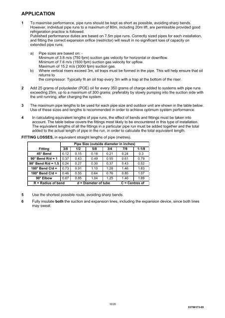
4 In calculating equivalent lengths of pipe runs, the effect of bends and fittings must be taken into<br />
account. The table below covers the fittings most likely to be encountered in this type of installation.<br />
The equivalent lengths of all the fittings in a particular pipe run must be added together and the total<br />
added to the actual length of pipe in the run, in order to calculate the total equivalent length.<br />
FITTING LOSSES, in equivalent straight lengths of pipe (metres).<br />
Pipe Size (outside diameter in inches)<br />
Fitting 3/8 1/2 5/8 3/4 7/8 1-1/8<br />
45° Bend 0.12 0.15 0.18 0.21 0.24 0.3<br />
90° Bend R/d = 1 0.37 0.43 0.49 0.55 0.61 0.79<br />
90° Bend R/d = 1.5 0.24 0.27 0.30 0.37 0.43 0.52<br />
180° Bend C/d = 0.73 0.91 1.10 1.28 1.46 1.83<br />
180° Bend C/d = 0.46 0.55 0.64 0.76 0.85 1.07<br />
90° Elbow 0.67 0.85 1.04 1.25 1.46 1.89<br />
R = Radius of bend d = Diameter of tube C = Centres of<br />
5 Use the shortest possible route, avoiding sharp bends.<br />
6 Fully insulate both the suction and expansion lines, including the expansion device, since both lines<br />
may sweat.<br />
10/20<br />
53799173-05