Analog Electronic Volt-Ohm-Milliammeters
Analog Electronic Volt-Ohm-Milliammeters
Analog Electronic Volt-Ohm-Milliammeters

Create successful ePaper yourself
Turn your PDF publications into a flip-book with our unique Google optimized e-Paper software.
<strong>Analog</strong> <strong>Electronic</strong><br />
<strong>Volt</strong>-<strong>Ohm</strong>-<strong>Milliammeters</strong><br />
4<br />
Objectives<br />
You wiU be able to:<br />
l. Sketch various transistor analog voltmeter circuits, and explain the operation of each<br />
circuit. Calculate circuit currents, voltages, and input resistance.<br />
2. Sketch an input aUenuator circuit as used with an electronic voltmeter. Explain its operation,<br />
and define the circuit input resistance.<br />
3. Using illustrations, explain the problems that can occur with electronic voltmeter<br />
ground terminals when measuring voltages in a circuit.<br />
4. Draw the circuit diagrams of various op-amp analog voltmeters. Explain the operation<br />
of each circuit.<br />
5. Draw series, shunt, and linear ohmmeter circuits as used in electronic instruments, and<br />
explain the operation of each circuit.<br />
6. Sketch the circuit diagrams of various ac electronic voltmeters, and explain their operation.<br />
7. Sketch a circuit to show how current is measured by an electronic voltmeter. Explain<br />
the circuit operation.<br />
8. Draw the front panel of a typical analog electronic voltmeter showing the various controls<br />
and meter scales. State typical performance specifications for the instrument, and<br />
discuss its applications.<br />
Introduction<br />
<strong>Volt</strong>meters constructed of moving-coil instruments and multiplier resistors (see Chapter<br />
3) have some important limitations. They cannot measure very low voltages, and their<br />
resistance is too low for measurements in high-impedance circuitry. These restrictions<br />
86
are overcome by the use of electronic circuits that offer high input resistance, and which<br />
amplify low voltages to measurable levels. When such circuits are used, the instrument<br />
becomes an electronic voltmeter.<br />
<strong>Electronic</strong> voltmeters can be analng instruments, in which the measurement is indicated<br />
by a pointer moving over a calibrated scale, or digital instruments, which display<br />
the measurement in numerical form (see Chapter 5). As well as amplification, transistor<br />
and operational amplifier circuits offer advantages in the measurement of resistance, direct<br />
current, and alternating current.<br />
4-1 TRANSISTOR VOLTMETER CIRCUITS<br />
Emitter-Follower <strong>Volt</strong>meters<br />
<strong>Volt</strong>meter loading (see Section 3-4) can be greatly reduced by using an emitter follower.<br />
An emitter follower offers a high 4input resistance to voltages being measured, and provides<br />
a low output resistance to drive current through the coil of a deflection meter. The<br />
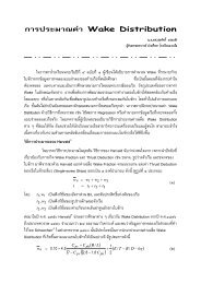
basic emitter-follower voltmeter circuit illustrated in Figure 4-1 shows a PMMC instrument<br />
and a multiplier resistance (Rs) connected in series with the transistor emitter. The<br />
dc supply is connected-positive to the transistor collector and the negative to the deflection<br />
meter. The positive terminal of voltage E (to be measured) is supplied to the transistor<br />
base, and its negative is connected to the same terminal as the power supply negative.<br />
The transistor base current in Figure 4-1 is substantially lower than the meter current.<br />
where hF£ is the transistor current gain. Thus, the circuit input resistance is<br />
,------0+<br />
+o----------~---~<br />
F"lgUre 4-1 An emitter follower offers a<br />
high input resistance to a measured voltage,<br />
and a low output resistance to a dellection<br />
voltmeter circuil V SE introduces an error in<br />
the measurement.<br />
Sec. 4-\<br />
Transistor <strong>Volt</strong>meter Circuits<br />
87
E<br />
R·=<br />
• 18<br />
which is much larger than the meter circuit resistance (Rs + Rm).<br />
Example 4-1<br />
The simple emitter-follower voltmeter circuit in Figure 4-1 has Vee =20 V, Rs + Rm =<br />
9.3 ill, 1m =1 rnA at full scale, and transistor hF£ = 100.<br />
(a) Calculate the meter current when E = 10 V,<br />
(b) Detennine the voltmeter input resistance with and without the transistor.<br />
Solution<br />
(a)<br />
VE = E - VBi';= to V - 0.7 V<br />
=9.3 V<br />
V E 9.3 V<br />
Im= Rs+Rm = 9.3 kfl<br />
=1 rnA<br />
(b) With the transistor.<br />
IB= ~ = 1 rnA<br />
hF/, 100<br />
= 10 fJ-A<br />
Without the transistor.<br />
R=.!i=~<br />
• IB to fJ-A<br />
= I Mfl<br />
The transistor base--emitter voltage drop (VBd introduces an error in the simple<br />
emitter-follower voltmeter. For example, when E is 5 V in the circuit in Example 4-1, the<br />
meter should read half of full-scale, that is, 0.5 rnA. However, as a simple calculation<br />
shows, the meter current is actually 0.46 rnA. The error can be eliminated by using a potential<br />
divider and an additional emitter follower, as illustrated in Figure 4-2.<br />
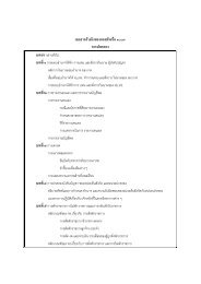
The practical emitter-follower circuit in Figure 4-2 uses a plus-and-minus. or dualpolarity<br />
supply (typically, ±12 V). Transistor Q\ has its base biased to ground via resistor<br />
Rio and a potential divider (R 4, Rs. and R6 ) provides an adjustable bias voltage (Vp) to the<br />
base of transistor Q2' Resistors R2 and R3 connect the transistor emitter terminals to the<br />
negative supply voltage (-V£d, and the meter circuit is connected between the transistor<br />
emitters. The circuit input resistance is R \ in parallel with the input resistance at the transistor<br />
base.<br />
88 <strong>Analog</strong> <strong>Electronic</strong> <strong>Volt</strong>-<strong>Ohm</strong>-Millimeters Chap. 4<br />
Ql
-------------------------------~-------.----~+voc<br />
t Rs RIO <br />
E <br />
1 I-+-------V---------~<br />
~----------------------------~~-----.----~ -VEE<br />
F"lgure 4-2 Practical emitter-follower voltmeter cffi;uit using a second transistor (Q2)<br />
and a potential divider (R4• Rs. and R 6) to eliminate the Vs£error produced by Qt.<br />
When no input voltage is applied (E =0 V). the base voltage of Q2 is adjusted to give<br />
zero meter current. This makes Vp =0 V. VEl =VEl =-0.7 V. and (meter circuit voltage) V=<br />
o V. Now suppose that a 5 V input is applied to the Q\ base. The meter voltage is<br />
V= VEl - V E2<br />
= (E - V BE1 ) - V E2<br />
=(5 V -0.7 V)-(-0.7 V)<br />
=5V<br />
Thus. unlike the case of the simple emitter-follower voltmeter, all of the voltage to be<br />
measured appears across the meter circuit; no part of it is lost as transistor VBE.<br />
Example 4-2<br />
An emitter-follower voltmeter circuit such as that in Figure 4-2 has R2 =R3 =3.9 kfi and<br />
Vcc=±l2 V.<br />
(a) Determine 12 and 13 when E =0 V.<br />
(b) Calculate the meter circuit voltage when E = I V and when E =0.5 V.<br />
Solution<br />
(a) VR2 = VR3 = 0 V - VBE - VEE <br />
=OV-O.7V-(-12V) <br />
= 11.3 V<br />
[_/_ VR2 _<br />
Il.3V<br />
2 - 3 - Rz - 3.9 kfl<br />
= 2.9mA<br />
Sec.4-1 Transistor <strong>Volt</strong>meter Circuits 89
(b) When E= 1 V.<br />
VEl =E- V8g =1 V -0.7 V<br />
=0.3 V<br />
VEl =Vp- V8g ==0 V -0.7 V<br />
=-0.7V<br />
V= Vgl - V E2 =0.3 V -(-0.7 V)<br />
WhenE=O.5 V.<br />
==IV<br />
VIOl ==E- VBg =O.5 V -0.7 V<br />
=-0.2V<br />
VEl == Vp - VBg '" 0 V - 0.7 V<br />
=-0.7V<br />
V= VIOl - V E2 == -0.2 V - (-0.7 V)<br />
=0.5 V<br />
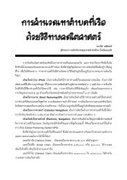
Ground Terminals and Floating Power Supplies<br />
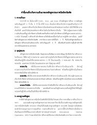
The circuit in Figure 4-2 shows the input voltage E as being measured with respect to<br />
ground. However, this may not always be convenient. For example, suppose that the voltage<br />
across resistor Rb in Figure 4-3(a) were to be measured by a voltmeter with its negative<br />
terminals grounded. The voltmeter ground would short-circuit resistor Rc and seriously<br />
affect the voltage and current conditions in the resistor circuit. Clearly, the<br />
voltmeter should not have one of its terminals grounded.<br />
For the circuit in Figure 4-2 to function correctly, the lower end of RI must be at<br />
zero volts with respect to +Vcc and -Vee. The + and - supply voltage may be derived<br />
from two batteries [Figure 4-3(b)] or from two de power supply circuits [Figure 4-3{c)J.<br />
[n both cases, the negative terminal of the positive supply is connected to the positive terminal<br />
of the negative supply. For ±9 V supplies, Vee is +9 V with respect to the common<br />
terminal, and Vee is -9 V with respect to the common terminal. [n many electronic circuits.<br />
the power supply common terminal is grounded. In electronic voltmeter circuits.<br />
this terminal is not grounded, simply to avoid the kind of problem already discussed.<br />
When left without any grounded terminal. the voltmeter supply voltages are said to be<br />
floating. This means that the common terminal assumes the absolute voltage (with respect<br />
to ground) of any terminal to which it may be connected. An inverted triangular symbol<br />
is employed to identify the common terminal or zero voLtage tenninaL in a circuit [see<br />
Figure 4-3(b),(c)].<br />
Although the electronic voltmeter supply voltages are allowed to float, some instlUments<br />
have their common terminal connected to ground via a capacitor. usually 0.1<br />
fLF. If batteries are used as supply, the capacitor is connected to the chassis. Where a<br />
90 <strong>Analog</strong> <strong>Electronic</strong> <strong>Volt</strong>-Ohrn-Millimeters Chap. 4
<strong>Volt</strong>meter<br />
+£0-----,<br />
R"<br />
Short circuit<br />
(a) A voltmeter with one of<br />
it's tenninals grounded can<br />
short..drcuit a component<br />
in a circuit in which voltage<br />
is being measured ..<br />
+Vee 0---------'<br />
+Vcc~+<br />
Common<br />
terminal<br />
CirCUilSymbol~<br />
forcommom <br />
tenninal<br />
+ <br />
Common terminal<br />
-VEE~-<br />
(b) : supply using batteries<br />
-<br />
VEE o-----~<br />
(c) ~ supply using power supplies<br />
Figure 4-3 Serious measurement errors can result when a grounded voltmeter terminal is incorrectly<br />
connected to a circuit. When a circuit has a plus-and .. minus supply voltage, the voltmeter common<br />
terminal should always be connected to the common terminal of the supply.<br />
liS V power supply is included in the voltmeter. the chassis and the capacitor are<br />
grounded. Thus. when measuring voltage levels in a transistor circuit, for example. the<br />
common terminal introduces a capacitance to ground wherever it is connected in the circuit.<br />
To avoid any effect on conditions within the circuit (oscillations or phase shifts).<br />
the voltmeter common terminal should always be connected to the transistor circuit<br />
ground or zero voltage terminal. All voltages are then measured with respect to this<br />
point..<br />
Sec. 4.1<br />
Transistor <strong>Volt</strong>meter Circuits<br />
91<br />
b
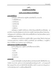
<strong>Volt</strong>meter Range Changing<br />
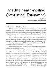
The potential divider constituted by resistors Rm R b, Re, and Rd in Figure 4-4 allows large<br />
input voltages to be measured on an emitter-follower voltmeter. This network, called an<br />
input attenuator; accurately divides the voltage to be measured before it is applied to the<br />
input transistor. Calculation shows that the Q3 input voltage (Ed is always I V when the<br />
maximum input is applied on any range. For example, on the 5 V range,<br />
EG =5 V X<br />
Rb + Rc + Rd <br />
Ra + Rb + Rc + Rd <br />
=5 V x looko'+60 ko' +40 ko'<br />
800 kfl + 100 kfi +60kfl+40 kfi<br />
=lV<br />
The input resistance offered by this circuit to a voltage being measured is the total<br />
resistance of the attenuator, which is 1 Mo'. A 9 Mfl resistor could be induded in series<br />
with the input terminal to raise the input resistance to 10 MO. This would further divide<br />
the input voltage by a factor of 10 before it is applied to the gate terminal of Q3'<br />
FET.Input <strong>Volt</strong>meter<br />
The input resistance of the transistor voltmeter circuit can be increased further by using<br />
an additional emitter follower connected at the base of Q. in Figure 4-2. However, the use<br />
1 1 FET 1<br />
1 iii Input ~loE input ~111i<br />
1 attenuator<br />
I<br />
1 stage 1<br />
I 1<br />
• 1<br />
1<br />
1<br />
1<br />
800k<br />
5V<br />
IV<br />
Emitter-follower<br />
voltmeter<br />
~<br />
+<br />
100 k<br />
R4<br />
Vee<br />
E<br />
60k<br />
Rs<br />
40k<br />
R6<br />
VEE<br />
Figure 4-4 A voltmeter input attenuator is simply a potential divider that accurately divides the<br />
voltage to be measured. The FET input stage (Q) gives .he emitter follower a very high input resistance.<br />
92 <strong>Analog</strong> <strong>Electronic</strong> <strong>Volt</strong>-<strong>Ohm</strong>-Millimeters Chap. 4
of a FET source follower (Q3)' as illustrated in Figure 4-4 gives a higher input resistance<br />
than can be achieved with a bipolar transistor. The PET source terminal is able to supply<br />
all of the base current required by Q" while the input resistance at the FEr gate is typically<br />
in ex.cess of 1 MO.. .<br />
Consider the voltage levels in the circuit of Figure 4-4. When E = 0 V, the PET gate<br />
is at the zero voltage level. But the gate of an n-channel PET must always be negative<br />
with respect to its source terminal. This is the same as stating that the source must be positive<br />
with respect to the gate. [f Vos is to be -5 V, and Eo =0 V, the source te~inal voltage<br />
must be +5 V. This means that the base t~al of Q. is at +5 V, and, since Q2 base<br />
voltage must be equal to Q. base voltage, Q2 base must also be at +5 V. As in the circuit<br />
of Figure 4-2, Rs in Figure 4-4 is used to zero the meter when the input voltage is 0 V.<br />
Now consider what occurs when a voltage to be measured is applied to the circuit<br />
input. With the attenuator shown, Ea will be a maximum of 1 y.This causes the PET<br />
source terminal to increase until Vas is again -5 Y. That is, ~ goes from +5 to -t{i V to<br />
maintain Vas equal to -5 V. The ~ increase of 1 V is also a 1 V increase in the base voltage<br />
of Q •. As already ex.plained, all of this (1 V) increase appears across the meter circuit.<br />
Example 4-3<br />
Determine the meter reading for the circuit in Figure 4-4 when E =7.5 V and the meter is<br />
set to its 10 V range. The PET gate-source voltage is -5 V, Vp = +5 V, Rs + Rm = 1 ka,<br />
and 1m = I rnA at full scale.<br />
Solution On the 10 V range: .<br />
=7.5 V x 60 kfl +40 kfl<br />
800 kfl + tOO kfl + 60 kfl + 40 kfl<br />
=0.75 V<br />
Vs=EG- VGs=0.75 V -(-5 V).<br />
=5.75 V<br />
VEl = Vs - V8E =5.75 V -0.7 V = 5.05 V<br />
Va= Vp -<br />
VBE =5 V -0.7 V<br />
=4.3 V<br />
V= VEl - VEl:;: 5.05 V -4.3 V<br />
=0.75 V =EG<br />
[= V 0.75 V<br />
m Rs+Rm =lkfi<br />
== 0.75 rnA (75% of full scale)<br />
. Sec. 4-1 Transistor <strong>Volt</strong>meter Circuits 93
On the 10 V range, full scale represents 10 V. and 75% offull scale would be<br />
read as 7.5 V.<br />
Difference Amplifier <strong>Volt</strong>meter<br />
The instruments discussed so far can measure a maximum of around 25 V. This could<br />
be extended further, of course, simply by modifying the input attenuator. The minimum<br />
(full-sCale) voltage measurable by the electronic voltmeter circuits already considered is<br />
I V. This too can., be altered to perhaps a minimum of 100 mV by selection of a meter<br />
that will give FSD when 100 mV appears across Rs + Rm. However, for accurate measurement<br />
of low voltage levels, the voltage must be amplified before it is applied to the<br />
meter.<br />
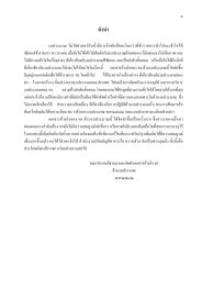
Transistors QI and Q2 together with RLI , Ru, and RE in Figure 4-5(a) constitute a<br />
differential amplifier, or emitter-coupled amplifier. The circuit as a whole is known as a<br />
difference amplifier voltmeter. This is because when the voltage at the base of Q2 is zero,<br />
and an input voltage (E) is applied to the Q. base, the difference between the two base<br />
voltages is amplified and applied to the meter circuit.<br />
When a small positive voltage is applied to the base of QI in Figure 4-5, the current<br />
through QI is increased, and that through Q2 is decreased. An increase in lei causes<br />
fetR LI to increase and thus produces a fall in voltage Vet. Similarly, a decrease in fez produces<br />
a rise in Vez. The consequence of this is that the voltage across the meter circuit increases<br />
positively at the right-hand side and negatively at the left. This meter voltage (\I)<br />
is directly proportional to the input voltage (E).<br />
+Vcc<br />
Ru<br />
Ru<br />
,----o+vcc<br />
ICl t<br />
VCl<br />
Rs<br />
Rm<br />
V<br />
VC2<br />
~ ~<br />
fa<br />
R2<br />
Ru<br />
(b) Zero control<br />
i<br />
1£1 ----- -1£2<br />
RE<br />
-VEE<br />
(a) <strong>Volt</strong>meter circuit<br />
Figure 4-5 A difference amplifier voltmeter amplifies low-level input voltages for measurement on<br />
the deflection voltmeter circuit.<br />
94 <strong>Analog</strong> <strong>Electronic</strong> <strong>Volt</strong>-<strong>Ohm</strong>-Millimeters Chap. 4
Potentiometer R3 in Figure 4-5(b) is an alternative method of providing meter-zero<br />
adjustment. Q2 base control, as in Figure 4-4, could also be used in the circuit of Figure<br />
4-5. When the movable contact of R3 is adjusted to the right, the portion of R3 added to<br />
RLI is increased and the portion of R3 added to Ru is reduced. When the contact is moved<br />
left, the reverse is true. Thus, VC\ and VC2 can be adjusted differentially by means of R 3 •<br />
and the meter voltage can be set to zero.<br />
4-2 OPERATIONAL AMPLIFIER VOLTMETER CIRCUITS<br />
Op-Amp <strong>Volt</strong>age-Follower <strong>Volt</strong>meter<br />
The operational amplifier voltage-follower voltmeter in Figure 4-6 is comparable to the<br />
simple emitter-follower circuit. However, unlike the emitter-follower, there is no baseemitter<br />
voltage drop from input to output. The voltage-foLLower also has a much higher<br />
input resistance and lower output resistance than the emitter-follower. The voltagefoLLower<br />
input (£8) is applied to the op-amp noninverting input terminaL, and the<br />
feedback from the output goes to the inverting input The very high internal voltage<br />
gain of the operational amplifier, combined with the negative feedback, tends to keep<br />
the inverting terminal voltage exactly equal to that at the noninverting terminal. Thus.<br />
the output voltage (Vo) exactly follows the input. As discussed earlier, the attenuator<br />
selects the voltmeter range.<br />
I I I I<br />
I<br />
I<br />
10(<br />
lnput<br />
I Meter<br />
I<br />
~ I 0( <strong>Volt</strong>age follower --_~+I""o(-- . . _<br />
I<br />
attenuator<br />
I<br />
CirCUit<br />
I<br />
I I I<br />
I I I<br />
I I I<br />
I I I<br />
I I I<br />
I I I<br />
I<br />
I<br />
:o---~~----,<br />
I<br />
I<br />
I I I<br />
I I I<br />
I<br />
Figure 4·6 An Ie operational amplifier voltage-follower voltmeter is similar to the<br />
emitter ·follower voltmeter. except that the voltage-fOllower input resistance is much<br />
higher than that of the emitter follower. and there is no base~miner voltage drop.<br />
Sec. 4-2 Operational Amplifier <strong>Volt</strong>meter Circuits 95
Op-Amp Amplifier <strong>Volt</strong>meter<br />
Like a transistor amplifier, an IC operational amplifier circuit can be used to amplify low<br />
voltages to levels measurable by a deflection instrument. Figure 4-7 shows a suitable opamp<br />
circuit for this purpose. Input voltage E is applied to the op-amp noninverting input,<br />
the output voltage is divided across resistors R3 and R 4, and VR3 is fed back to the op-amp<br />
inverting input terminal. The internal voltage gain of the op-amp causes VR3 to always<br />
equal E. Consequently, the output voltage is<br />
v = E_R..:;..3_+_R -'..4 (4-1)<br />
o R3<br />
The circuit is known as a noninverting ampLifie 1; because its output is positive when a positi ve<br />
input voltage is applied, and negative when the input is a negative quantity. The noninverting<br />
amplifier has a very high input resistance, very low output resistance, and a voltage gain of<br />
(4-2)<br />
1 1 1<br />
1<br />
10(<br />
Noninverting<br />
amplifier<br />
------...,..~:f.o(f__- Meter<br />
circuit ------:<br />
1<br />
1<br />
1<br />
1<br />
1<br />
t<br />
E<br />
Figure 4-7 An operational amplifier noninverting amplifier can be used to amplify low<br />
input voltages to a level suitable for the deflection meter circuit. The voltmeter gain is<br />
(R3 + R4 )IR3·<br />
96 <strong>Analog</strong> <strong>Electronic</strong> <strong>Volt</strong>-<strong>Ohm</strong>-Millimeters Chap. 4
An op-amp noninverting amplifier voltmeter is very easily designed. Current 14<br />
through R3 and ~ is first selected very much larger than the op-amp input bias current<br />
(I8)' Then the resistors are calculated as<br />
and<br />
Example 4-4<br />
An op-amp voltmeter circuit as in Figure 4-7 is required to measure a maximum input of<br />
20 mV. The op-amp input current is 0.2 JLA. and the meter circuit has I". = 100 fLA FSD<br />
and Rm =10 kil. Determine suitable resistance values for R3 and R 4 •<br />
Solution<br />
Select<br />
[4 = 1000 X In =1000 x 0.2 !-LA<br />
=0.2mA<br />
Atfull scale,<br />
and<br />
1m =100 V-A<br />
=IV<br />
= 100 n<br />
R4 = Vo - E = I V - 20 mV<br />
14 0.2mA<br />
=4.9 kil<br />
<strong>Volt</strong>age-to-Current Converter<br />
The circuit shown in Figure 4-8 is essentially a noninverting amplifier. as in Figure 4-7.<br />
However. instead of connecting the meter between the op-amp output and ground. it is<br />
substituted in place of resistor R4 (in Figure 4-7). Once again. V R1 remains equal to the<br />
input voltage. and as long as IRl is very much greater than lB. the meter current is<br />
(4-3)<br />
Sec. 4-2 Operational Amplifier <strong>Volt</strong>meter Circuits 97
E<br />
1<br />
Figure 4-8 <strong>Volt</strong>meter circuit using an<br />
op-amp voltage-to-current converter. The<br />
meter current is F/R3'<br />
Example 4-5<br />
Calculate the value of R3 for the circuit in Figure 4-8 if E = 1 V is to give FSD on the<br />
meter. The moving-coil meter has 1= 1 rnA at full scale and Rnr = 100 n. Also detennine<br />
the maximum voltage at the operational amplifier output terminaL<br />
Solution From Equation 4-3,<br />
E<br />
1 V<br />
R) = -- = -- = 1 kfl<br />
I(FSD) 1 rnA<br />
Vo = I(R 3 + Rm)<br />
= 1 mA(l kfl + 100 fl)<br />
=1.1 V
Many electronic rnultirange instruments do not have any current-measuring facilities.<br />
Those that do measure current generally have very low-level current ranges, and<br />
some have relatively high resistances when operating as ammeters. For example, the<br />
meter resistance on one instrument is specified as 9 kfl when operating on a 1.S fJ.A<br />
range. This must be taken into account when the instrument is connected in series with a<br />
circuit in which the current is to be measured. The instrument terminal voltage drop when<br />
used as an ammeter is termed the burden voltage. For a 9 kfl resistance on a 1.5 ILA<br />
range, the burden voltage is<br />
V B =9 kn x 1.S ILA= 13.5 mV<br />
Other typical burden voltage specifications are 250 mV max, 2 Von a 10 A range. and<br />
6 mVIrnA. These voltages drops mayor may not be important, depending on the circuit<br />
under test.<br />
PROBLEMS<br />
4-1 A simple emitter-follower voltmeter circuit as in Figure 4-1 has Vee = 12 V, Rm =<br />
1 kfl. a 2 rnA meter, and a transistor with hF£ = 80. Calculate a suitable resistance<br />
for R. to give full scale deflection when E = 5 V. Also, determine the voltmeter<br />
input resistance.<br />
4-2 An emitter-follower voltmeter circuit, as in Figure 4-2, has the following components:<br />
R, = 12 kfl, R2 =R3 =2.1. kG, R4 =14 =3.3 kfl, Rs =SOO n, and R. + Rm =<br />
10 kG. A 100 f1A meter is used, the supply voltage is ±9 V, and the transistors have<br />
hF£ =7S. Determine V p ' [81, [82, [2. [3, and 14 when E = O. Also, calculate the range<br />
of adjustment for Vp.<br />
4-3 Calculate the meter deflections for the circuit in Probl~m 4-2 when the input voltage<br />
levels are 0.6 V, 0.75 V, and 1 V.<br />
4-4 A 3.S V input (E) is applied to the input attenuator shown in Figure 4-4. Calculate<br />
the voltage EG on each range selection.<br />
4-5 The FET input voltmeter circuit in Figure 4-4 has the following components: R, =<br />
6.8 kG, R2 = R3 =4.7 kil, R4 = 1.5 kG. Rs = 500 il, R6 =3.3 kG, R. + Rm = 20 kG.<br />
The meter full-scale current is 50 ILA, the supply voltage is ±10 V, the transistors<br />
Problems 115
• <br />
have hFE = 80, and the FET gate-source voltage is VGS = -3 V. Determine V p ' In 1 2,<br />
1 3 , and 14 when E = O. Also, calculate the range of adjustment for Vp.<br />
4-6 Calculate the meter deflectio(ls for the circuit in Problem 4-5 when the attenuator is<br />
set to its 5 V range, and the input voltage levels are I V, 3 V, and 4 Y.<br />
4-7 The difference amplifier voltmeter in Figure 4-5(a) has the following components:<br />
Rl = R2 = 15 kfl, RLi = RL2 =3.9 kfl, R£ = 3.3 kfl, Rs = 33 kfl, and Rm =<br />
750 fl. The meter full-scale current is 50 ~A, and the supply voltage is ±12 Y.<br />
Calculate the transistor voltage levels when E = o.<br />
4-8 The circuit in Problem 4-7 has transistors with hFE = 100 and hi~ = 1.2 kfl. Determine<br />
the input voltage (E) that will give full-scale deflection on the meter.<br />
4-9 An op-amp voltage-follower voltmeter, as in Figure 4-6, has Ra = 800 kfl, Rb =<br />
100 kfl, Rc = 60 kfl, and Rd = 40 kfl. A 50 ~A meter is used with a resistance of<br />
Rm = 750 fl. Determine the required resistance for Rs to give full-scale deflection<br />
when E = 10 V and the range switch is as illustrated.<br />
4-10 The noninverting amplifier voltmeter circuit in Figure 4-7 uses an op-amp with I B = .<br />
300 nA, and a 50 /LA meter with Rm = 100 kfl. Determine suitable resistances for<br />
R3 and R4 to give full-scale deflection when the input is 300 mY.<br />
4-11 The voltage-to-current converter circuit in Figure 4-8 uses a 37.5 /LA (FSD) deflection<br />
meter with Rm =900 fl. If R) =80 kfl, determine the required input voltage<br />
levels to give FSD and 0.5 FSD.<br />
4-12 Determine the new resistance for R3 for the circuit in Problem 4-11 to give FSD<br />
when E = 1 V. Also, calculate the op-amp output voltage.<br />
4-13 Calculate the resistance scale markings at 25% and 75% of full scale for the series<br />
ohmmeter circuit in Figure 4-9.<br />
4-14 Determine the percentage meter deflection in the circuit of Figure 4-9 when the<br />
100 kfl standard resistor is switched into the circuit and Rx = 166 kfl.<br />
4-15 Calculate the meter deflection for the shunt ohmmeter circuit in Figure 4-10 when<br />
Rx =2 kO and when Rx =300 O.<br />
4-16 A 16.67 kO resistor is substituted for RE in the linear ohmmeter circuit in Figure<br />
4-11. Calculate the measured resistance when the meter indicates 3.9 V.<br />
4-17 The half-wave rectifier electronic voltmeter in Figure 4-12(b) uses a 500 ~A deflection<br />
meter with a 460 fl coil resistance. If Rs = 450 fl, calculate the rms input voltage<br />
required to give full-scale deflection.<br />
4-18 The components used in Problem 4-17 are reconnected as in Figure 4-13(a) with<br />
R3 = Rs. Determine the new rms input voltage required to give full-scale deflection.<br />
Also determine the meter deft.ections when the input is 100 mV and 200 mY.<br />
4-19 The ac electronic voltmeter circuit in Figure 4-12(c) uses the following components:<br />
R, = 22 kfl, R2 = 2.25 kfl, R3 = 6.8 kfl, Rs + Rm = 1 kfl, and a 300 J.LA<br />
meter. Calculate the rms input voltages for meter fun-scale deflection and for 0.5<br />
FSD.<br />
4-20 The full-wave rectifier voltmeter circuit in Figure 4-13(b) uses a 500 ~A meter<br />
with Rm =460 n together with R) = 450 n (as for Problems 4-17 and 4-18). Determine<br />
the rms input voltage for FSD on the meter.<br />
116 <strong>Analog</strong> <strong>Electronic</strong> <strong>Volt</strong>-<strong>Ohm</strong>-Millimeters Chap. 4