Quietpact 40G Diagnostic Repair Manual Model 4700 - Generac Parts
Quietpact 40G Diagnostic Repair Manual Model 4700 - Generac Parts
Quietpact 40G Diagnostic Repair Manual Model 4700 - Generac Parts

Create successful ePaper yourself
Turn your PDF publications into a flip-book with our unique Google optimized e-Paper software.
Section 2<br />
Major Generator Components<br />
Breather Assembly<br />
VOLTAGE<br />
ADjUST POT<br />
11S 22S<br />
4<br />
Ok<br />
6<br />
2A<br />
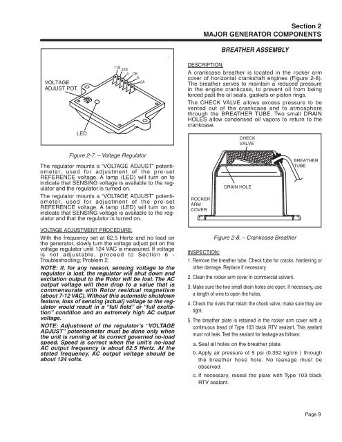
DESCRIPTION:<br />
A crankcase breather is located in the rocker arm<br />
cover of horizontal crankshaft engines (Figure 2-8).<br />
The breather serves to maintain a reduced pressure<br />
in the engine crankcase, to prevent oil from being<br />
forced past the oil seals, gaskets or piston rings.<br />
The CHECK VALVE allows excess pressure to be<br />
vented out of the crankcase and to atmosphere<br />
through the BREATHER TUBE. Two small DRAIN<br />
HOLES allow condensed oil vapors to return to the<br />
crankcase.<br />
LED<br />
CHECK<br />
VALVE<br />
Figure 2-7. – Voltage Regulator<br />
The regulator mounts a “VOLTAGE ADJUST” potentiometer,<br />
used for adjustment of the pre-set<br />
REFERENCE voltage. A lamp (LED) will turn on to<br />
indicate that SENSING voltage is available to the regulator<br />
and the regulator is turned on.<br />
The regulator mounts a “VOLTAGE ADJUST” potentiometer,<br />
used for adjustment of the pre-set<br />
REFERENCE voltage. A lamp (LED) will turn on to<br />
indicate that SENSING voltage is available to the regulator<br />
and that the regulator is turned on.<br />
ROCKER<br />
ARM<br />
COVER<br />
DRAIN HOLE<br />
BREATHER<br />
TUBE<br />
Voltage ADJUSTMENT PROCEDURE:<br />
With the frequency set at 62.5 Hertz and no load on<br />
the generator, slowly turn the voltage adjust pot on the<br />
voltage regulator until 124 VAC is measured. If voltage<br />
is not adjustable, proceed to Section 6 -<br />
Troubleshooting; Problem 2.<br />
NOTE: If, for any reason, sensing voltage to the<br />
regulator is lost, the regulator will shut down and<br />
excitation output to the Rotor will be lost. The AC<br />
output voltage will then drop to a value that is<br />
commensurate with Rotor residual magnetism<br />
(about 7-12 VAC). Without this automatic shutdown<br />
feature, loss of sensing (actual) voltage to the regulator<br />
would result in a “full field” or “full excitation”<br />
condition and an extremely high AC output<br />
voltage.<br />
NOTE: Adjustment of the regulator’s “VOLTAGE<br />
ADJUST” potentiometer must be done only when<br />
the unit is running at its correct governed no-load<br />
speed. Speed is correct when the unit’s no-load<br />
AC output frequency is about 62.5 Hertz. At the<br />
stated frequency, AC output voltage should be<br />
about 124 volts.<br />
Figure 2-8. – Crankcase Breather<br />
INSPECTION:<br />
1. Remove the breather tube. Check tube for cracks, hardening or<br />
other damage. Replace if necessary.<br />
2. Clean the rocker arm cover in commercial solvent.<br />
3. Make sure the two small drain holes are open. If necessary, use<br />
a length of wire to open the holes.<br />
4. Check the rivets that retain the check valve, make sure they are<br />
tight.<br />
5. The breather plate is retained in the rocker arm cover with a<br />
continuous bead of Type 103 black RTV sealant. This sealant<br />
must not leak. Test the sealant for leakage as follows:<br />
a. Seal all holes on the breather plate.<br />
b. Apply air pressure of 5 psi (0.352 kg/cm ) through<br />
the breather hose hole. No leakage must be<br />
observed.<br />
c. If necessary, reseal the plate with Type 103 black<br />
RTV sealant.<br />
Page 9