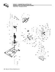
Quietpact 40G Diagnostic Repair Manual Model 4700 - Generac Parts
Quietpact 40G Diagnostic Repair Manual Model 4700 - Generac Parts
Quietpact 40G Diagnostic Repair Manual Model 4700 - Generac Parts

Create successful ePaper yourself
Turn your PDF publications into a flip-book with our unique Google optimized e-Paper software.
Section 7<br />
DIAGNOSTIC TESTS<br />
Introduction<br />
The “<strong>Diagnostic</strong> Tests” in this chapter may be performed<br />
in conjunction with the “Flow Charts” of<br />
Section 6. Test numbers in this chapter correspond to<br />
the numbered tests in the “Flow Charts”.<br />
Tests 1 through 17 are procedures Involving problems<br />
with the generator’s AC output voltage and frequency<br />
(Problems 1 through 4 in the “Flow Charts”).<br />
Tests 18 through 40 are procedures involving problems<br />
with engine operation (Problems 5 through 9 in the<br />
“Troubleshooting Flow Charts”).<br />
You may wish to read Section 4, “Measuring<br />
Electricity”.<br />
NOTE: Test procedures in this <strong>Manual</strong> are not<br />
necessarily the only acceptable methods for diagnosing<br />
the condition of components and circuits.<br />
All possible methods that might be used for system<br />
diagnosis have not been evaluated. If you<br />
use any diagnostic method other than the method<br />
presented in this <strong>Manual</strong>, you must ensure<br />
that nether neither your safety nor the product’s<br />
safety will be endangered by the procedure or<br />
method you have selected.<br />
Test 1 – Check No-Load Voltage and<br />
Frequency<br />
DISCUSSION:<br />
The first step in analyzing any problem with the AC<br />
generator is to determine the unit’s AC output voltage<br />
and frequency. Once that has been done, you will<br />
know how to proceed with specific diagnostic tests.<br />
PROCEDURE:<br />
1. Set a volt-ohm-milliammeter (VOM) to read AC voltage. Connect<br />
the meter test leads across customer connection leads T1<br />
(Red) and T2 (White).<br />
2. Disconnect or turn OFF all electrical loads. Initial checks and<br />
adjustments are accomplished at no-load.<br />
3. Start the engine, let it stabilize and warm up.<br />
4. Read the AC voltage.<br />
5. Connect an AC frequency meter across AC output leads T1<br />
(Black) and T2 (White). Repeat the above procedure.<br />
RESULTS:<br />
For units rated 60 Hertz, no-load voltage and frequency<br />
should be approximately 122-126 VAC and 61-63<br />
Hertz respectively.<br />
1. If AC voltage and frequency are BOTH correspondingly high or<br />
low, go to Test 2.<br />
2. If AC frequency is good but low or residual voltage is indicated,<br />
go to Test 3.<br />
3. If AC output voltage and frequency are both “zero”, go to Test 12.<br />
4. If the no-load voltage and frequency are within the stated limits,<br />
go to Test 13.<br />
NOTE: The term “low voltage” refers to any voltage<br />
reading that is lower than the unit’s rated voltage.<br />
The term “residual voltage” refers to the output<br />
voltage supplied as a result of Rotor residual magnetism<br />
(approximately 5-12 VAC).<br />
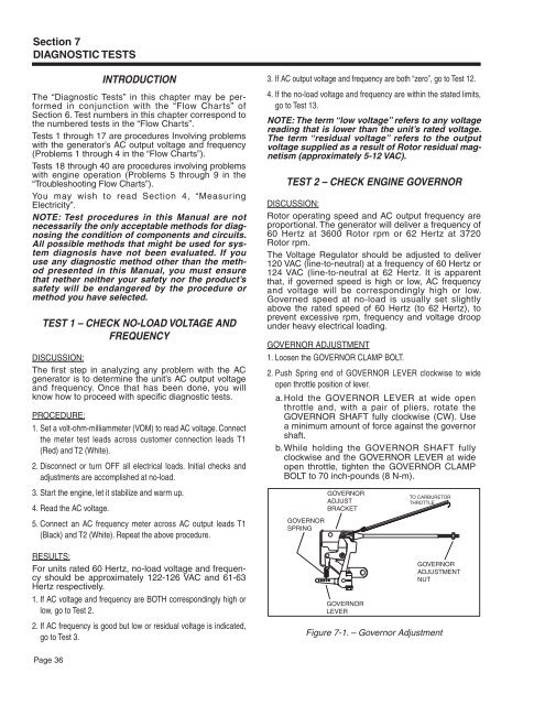
Test 2 – Check Engine Governor<br />
DISCUSSION:<br />
Rotor operating speed and AC output frequency are<br />
proportional. The generator will deliver a frequency of<br />
60 Hertz at 3600 Rotor rpm or 62 Hertz at 3720<br />
Rotor rpm.<br />
The Voltage Regulator should be adjusted to deliver<br />
120 VAC (line-to-neutral) at a frequency of 60 Hertz or<br />
124 VAC (line-to-neutral at 62 Hertz. It is apparent<br />
that, if governed speed is high or low, AC frequency<br />
and voltage will be correspondingly high or low.<br />
Governed speed at no-load is usually set slightly<br />
above the rated speed of 60 Hertz (to 62 Hertz), to<br />
prevent excessive rpm, frequency and voltage droop<br />
under heavy electrical loading.<br />
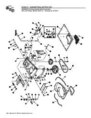
Governor Adjustment<br />
1. Loosen the GOVERNOR CLAMP BOLT.<br />
2. Push Spring end of GOVERNOR LEVER clockwise to wide<br />
open throttle position of lever.<br />
a. Hold the GOVERNOR LEVER at wide open<br />
throttle and, with a pair of pliers, rotate the<br />
GOVERNOR SHAFT fully clockwise (CW). Use<br />
a minimum amount of force against the governor<br />
shaft.<br />
b. While holding the GOVERNOR SHAFT fully<br />
clockwise and the GOVERNOR LEVER at wide<br />
open throttle, tighten the GOVERNOR CLAMP<br />
BOLT to 70 inch-pounds (8 N-m).<br />
GOVERNOR<br />
SPRING<br />
GOVERNOR<br />
ADjUST<br />
BRACkET<br />
GOVERNOR<br />
LEVER<br />
TO CARBURETOR<br />
THROTTLE<br />
GOVERNOR<br />
ADjUSTMENT<br />
NUT<br />
Figure 7-1. – Governor Adjustment<br />
Page 36