Quietpact 40G Diagnostic Repair Manual Model 4700 - Generac Parts
Quietpact 40G Diagnostic Repair Manual Model 4700 - Generac Parts
Quietpact 40G Diagnostic Repair Manual Model 4700 - Generac Parts

You also want an ePaper? Increase the reach of your titles
YUMPU automatically turns print PDFs into web optimized ePapers that Google loves.
Section 3<br />
Insulation Resistance Tests<br />
TEST BETWEEN PARALLEL WINDINGS:<br />
Connect the tester leads across Stator leads No. 11P<br />
and 33. Apply a voltage of 1500 volts. If an insulation<br />
breakdown is indicated, clean and dry the Stator.<br />
Then, repeat the test between parallel windings. If the<br />
Stator fails the second test, replace it.<br />
2<br />
11P<br />
22P<br />
33<br />
44<br />
66<br />
6<br />
55<br />
11S<br />
22S<br />
77<br />
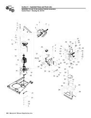
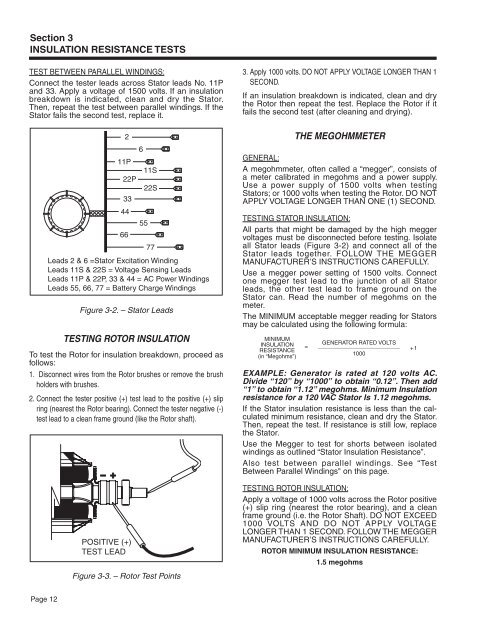
Leads 2 & 6 =Stator Excitation Winding<br />
Leads 11S & 22S = Voltage Sensing Leads<br />
Leads 11P & 22P, 33 & 44 = AC Power Windings<br />
Leads 55, 66, 77 = Battery Charge Windings<br />
Figure 3-2. – Stator Leads<br />
Testing Rotor Insulation<br />
To test the Rotor for insulation breakdown, proceed as<br />
follows:<br />
1. Disconnect wires from the Rotor brushes or remove the brush<br />
holders with brushes.<br />
2. Connect the tester positive (+) test lead to the positive (+) slip<br />
ring (nearest the Rotor bearing). Connect the tester negative (-)<br />
test lead to a clean frame ground (like the Rotor shaft).<br />
POSITIVE (+)<br />
TEST LEAD<br />
Figure 3-3. – Rotor Test Points<br />
3. Apply 1000 volts. DO NOT APPLY VOLTAGE LONGER THAN 1<br />
SECOND.<br />
If an insulation breakdown is indicated, clean and dry<br />
the Rotor then repeat the test. Replace the Rotor if it<br />
fails the second test (after cleaning and drying).<br />
The Megohmmeter<br />
GENERAL:<br />
A megohmmeter, often called a “megger”, consists of<br />
a meter calibrated in megohms and a power supply.<br />
Use a power supply of 1500 volts when testing<br />
Stators; or 1000 volts when testing the Rotor. DO NOT<br />
APPLY VOLTAGE LONGER THAN ONE (1) SECOND.<br />
TESTING STATOR INSULATION:<br />
All parts that might be damaged by the high megger<br />
voltages must be disconnected before testing. Isolate<br />
all Stator leads (Figure 3-2) and connect all of the<br />
Stator leads together. FOLLOW THE MEGGER<br />
MANUFACTURER’S INSTRUCTIONS CAREFULLY.<br />
Use a megger power setting of 1500 volts. Connect<br />
one megger test lead to the junction of all Stator<br />
leads, the other test lead to frame ground on the<br />
Stator can. Read the number of megohms on the<br />
meter.<br />
The MINIMUM acceptable megger reading for Stators<br />
may be calculated using the following formula:<br />
MINIMUM<br />
INSULATION<br />
RESISTANCE<br />
(in “Megohms”)<br />
=<br />
GENERATOR RATED VOLTS<br />
__________________________<br />
1000<br />
EXAMPLE: Generator is rated at 120 volts AC.<br />
Divide “120” by “1000” to obtain “0.12”. Then add<br />
“1” to obtain “1.12” megohms. Minimum Insulation<br />
resistance for a 120 VAC Stator Is 1.12 megohms.<br />
If the Stator insulation resistance is less than the calculated<br />
minimum resistance, clean and dry the Stator.<br />
Then, repeat the test. If resistance is still low, replace<br />
the Stator.<br />
Use the Megger to test for shorts between isolated<br />
windings as outlined “Stator Insulation Resistance”.<br />
Also test between parallel windings. See “Test<br />
Between Parallel Windings" on this page.<br />
TESTING ROTOR INSULATION:<br />
Apply a voltage of 1000 volts across the Rotor positive<br />
(+) slip ring (nearest the rotor bearing), and a clean<br />
frame ground (i.e. the Rotor Shaft). DO NOT EXCEED<br />
1000 VOLTS AND DO NOT APPLY VOLTAGE<br />
LONGER THAN 1 SECOND. FOLLOW THE MEGGER<br />
MANUFACTURER’S INSTRUCTIONS CAREFULLY.<br />
ROTOR MINIMUM INSULATION RESISTANCE:<br />
1.5 megohms<br />
+1<br />
Page 12